EP2806976B1 - Verfahren und anordnung zur abgasreinigung bei vakuum-stahlbehandlungsprozessen - Google Patents
Verfahren und anordnung zur abgasreinigung bei vakuum-stahlbehandlungsprozessen Download PDFInfo
- Publication number
- EP2806976B1 EP2806976B1 EP13704886.4A EP13704886A EP2806976B1 EP 2806976 B1 EP2806976 B1 EP 2806976B1 EP 13704886 A EP13704886 A EP 13704886A EP 2806976 B1 EP2806976 B1 EP 2806976B1
- Authority
- EP
- European Patent Office
- Prior art keywords
- gas
- cyclone
- fine dust
- waste gas
- dust filter
- Prior art date
- Legal status (The legal status is an assumption and is not a legal conclusion. Google has not performed a legal analysis and makes no representation as to the accuracy of the status listed.)
- Not-in-force
Links
- 238000000034 method Methods 0.000 title claims description 22
- 238000000746 purification Methods 0.000 title claims description 11
- 239000002912 waste gas Substances 0.000 title claims 11
- 229910000831 Steel Inorganic materials 0.000 title description 6
- 239000010959 steel Substances 0.000 title description 6
- 239000007789 gas Substances 0.000 claims description 73
- 239000000428 dust Substances 0.000 claims description 42
- 239000002245 particle Substances 0.000 claims description 16
- 238000001816 cooling Methods 0.000 claims description 12
- 238000000926 separation method Methods 0.000 claims description 9
- 238000004140 cleaning Methods 0.000 claims description 5
- 239000011261 inert gas Substances 0.000 claims description 5
- 239000011362 coarse particle Substances 0.000 claims description 4
- 229910001220 stainless steel Inorganic materials 0.000 claims description 3
- 239000010935 stainless steel Substances 0.000 claims description 3
- XLYOFNOQVPJJNP-UHFFFAOYSA-N water Substances O XLYOFNOQVPJJNP-UHFFFAOYSA-N 0.000 description 5
- 230000008021 deposition Effects 0.000 description 3
- 239000010419 fine particle Substances 0.000 description 3
- 239000007788 liquid Substances 0.000 description 3
- 239000000306 component Substances 0.000 description 2
- 238000010586 diagram Methods 0.000 description 2
- 238000001914 filtration Methods 0.000 description 2
- 238000004519 manufacturing process Methods 0.000 description 2
- 229910000975 Carbon steel Inorganic materials 0.000 description 1
- 238000009825 accumulation Methods 0.000 description 1
- QVGXLLKOCUKJST-UHFFFAOYSA-N atomic oxygen Chemical compound [O] QVGXLLKOCUKJST-UHFFFAOYSA-N 0.000 description 1
- 238000007664 blowing Methods 0.000 description 1
- 238000006243 chemical reaction Methods 0.000 description 1
- 238000002485 combustion reaction Methods 0.000 description 1
- 238000009833 condensation Methods 0.000 description 1
- 230000005494 condensation Effects 0.000 description 1
- 239000000498 cooling water Substances 0.000 description 1
- 239000008358 core component Substances 0.000 description 1
- 238000007872 degassing Methods 0.000 description 1
- 230000001419 dependent effect Effects 0.000 description 1
- 238000011161 development Methods 0.000 description 1
- 230000018109 developmental process Effects 0.000 description 1
- 238000009826 distribution Methods 0.000 description 1
- 238000001704 evaporation Methods 0.000 description 1
- 230000008020 evaporation Effects 0.000 description 1
- 238000004880 explosion Methods 0.000 description 1
- 239000004744 fabric Substances 0.000 description 1
- 230000009760 functional impairment Effects 0.000 description 1
- 238000002347 injection Methods 0.000 description 1
- 239000007924 injection Substances 0.000 description 1
- 238000012423 maintenance Methods 0.000 description 1
- 238000010310 metallurgical process Methods 0.000 description 1
- 229910052760 oxygen Inorganic materials 0.000 description 1
- 239000001301 oxygen Substances 0.000 description 1
- 239000013618 particulate matter Substances 0.000 description 1
- 230000035939 shock Effects 0.000 description 1
- 230000002269 spontaneous effect Effects 0.000 description 1
- 238000009628 steelmaking Methods 0.000 description 1
Images

Classifications
-
- B—PERFORMING OPERATIONS; TRANSPORTING
- B04—CENTRIFUGAL APPARATUS OR MACHINES FOR CARRYING-OUT PHYSICAL OR CHEMICAL PROCESSES
- B04C—APPARATUS USING FREE VORTEX FLOW, e.g. CYCLONES
- B04C9/00—Combinations with other devices, e.g. fans, expansion chambers, diffusors, water locks
-
- B—PERFORMING OPERATIONS; TRANSPORTING
- B01—PHYSICAL OR CHEMICAL PROCESSES OR APPARATUS IN GENERAL
- B01D—SEPARATION
- B01D45/00—Separating dispersed particles from gases or vapours by gravity, inertia, or centrifugal forces
- B01D45/12—Separating dispersed particles from gases or vapours by gravity, inertia, or centrifugal forces by centrifugal forces
-
- B—PERFORMING OPERATIONS; TRANSPORTING
- B01—PHYSICAL OR CHEMICAL PROCESSES OR APPARATUS IN GENERAL
- B01D—SEPARATION
- B01D46/00—Filters or filtering processes specially modified for separating dispersed particles from gases or vapours
- B01D46/42—Auxiliary equipment or operation thereof
- B01D46/4263—Means for active heating or cooling
-
- B—PERFORMING OPERATIONS; TRANSPORTING
- B01—PHYSICAL OR CHEMICAL PROCESSES OR APPARATUS IN GENERAL
- B01D—SEPARATION
- B01D50/00—Combinations of methods or devices for separating particles from gases or vapours
- B01D50/20—Combinations of devices covered by groups B01D45/00 and B01D46/00
-
- B—PERFORMING OPERATIONS; TRANSPORTING
- B04—CENTRIFUGAL APPARATUS OR MACHINES FOR CARRYING-OUT PHYSICAL OR CHEMICAL PROCESSES
- B04C—APPARATUS USING FREE VORTEX FLOW, e.g. CYCLONES
- B04C5/00—Apparatus in which the axial direction of the vortex is reversed
- B04C5/12—Construction of the overflow ducting, e.g. diffusing or spiral exits
-
- B—PERFORMING OPERATIONS; TRANSPORTING
- B04—CENTRIFUGAL APPARATUS OR MACHINES FOR CARRYING-OUT PHYSICAL OR CHEMICAL PROCESSES
- B04C—APPARATUS USING FREE VORTEX FLOW, e.g. CYCLONES
- B04C5/00—Apparatus in which the axial direction of the vortex is reversed
- B04C5/14—Construction of the underflow ducting; Apex constructions; Discharge arrangements ; discharge through sidewall provided with a few slits or perforations
- B04C5/15—Construction of the underflow ducting; Apex constructions; Discharge arrangements ; discharge through sidewall provided with a few slits or perforations with swinging flaps or revolving sluices; Sluices; Check-valves
-
- B—PERFORMING OPERATIONS; TRANSPORTING
- B04—CENTRIFUGAL APPARATUS OR MACHINES FOR CARRYING-OUT PHYSICAL OR CHEMICAL PROCESSES
- B04C—APPARATUS USING FREE VORTEX FLOW, e.g. CYCLONES
- B04C5/00—Apparatus in which the axial direction of the vortex is reversed
- B04C5/20—Apparatus in which the axial direction of the vortex is reversed with heating or cooling, e.g. quenching, means
-
- B—PERFORMING OPERATIONS; TRANSPORTING
- B04—CENTRIFUGAL APPARATUS OR MACHINES FOR CARRYING-OUT PHYSICAL OR CHEMICAL PROCESSES
- B04C—APPARATUS USING FREE VORTEX FLOW, e.g. CYCLONES
- B04C9/00—Combinations with other devices, e.g. fans, expansion chambers, diffusors, water locks
- B04C2009/004—Combinations with other devices, e.g. fans, expansion chambers, diffusors, water locks with internal filters, in the cyclone chamber or in the vortex finder
Definitions
- the invention relates to a method for exhaust gas purification according to the preamble of claim 1. Furthermore, the invention relates to an arrangement for exhaust gas purification according to a method of the invention.
- a method according to the preamble of claim 1 is known from DE 556 179 C known.
- the method known from the cited document has an arrangement for exhaust gas purification with a cyclone separator, a fine dust filter and a cooler.
- the exhaust gases to be cleaned are first passed through a heat exchanger, where they are cooled with heat release. Subsequently, the exhaust gases pass into a cyclone separator, where a coarse separation of particles takes place. Finally, the exhaust gas freed from the coarse particles passes into a fine dust filter, where a separation of fine dust takes place.
- the disadvantage here is that the exhaust gas is cooled before the deposition of the coarse particles and the fine particles in the cyclone and the particulate filter. As a result, a relatively large cooling device is required because the entire volume of the exhaust gas is cooled down.
- the systems for carrying out the aforementioned methods consist essentially of two core components, the so-called recipient on the one hand, in the ladles with liquid steel with a capacity of over 300t below Vacuum treated, and on the other hand, the vacuum generator, which is connected via a suction line to the recipient.
- the vacuum generator which is connected via a suction line to the recipient.
- dissolved gases as well as reaction gases are liberated, which are sucked off by the vacuum generator while maintaining the respective absolute working pressure.
- entrained metallic or non-metallic dust particles resulting from evaporation and condensation are carried along in the exhaust gas flow.
- the dust may be at an exhaust gas temperature of up to 500 ° C and a particle size of 0.5 ⁇ m to ⁇ 100 ⁇ m in a mass accumulation of 3kg to 4kg of dust per ton of liquid steel.
- the dust load in the exhaust gas is no direct functional impairment of the ejector.
- the exhaust gases are compressed here via multi-stage ejectors to atmospheric pressure, the dust contained in the exhaust gas is about 5% accumulate up to 10% on the walls of the pipes and ejectors and the remaining 90% to 95% of the circuit cooling water in the injection condensers washed out and discharged.
- high expenses for labor-intensive manual cleaning work and for cleaning the contaminated with the dust particles circulation water are to be regarded as disadvantageous.
- the vacuum generation by steam jet is also characterized by a high steam consumption, which must be generated locally in a steam generator high power, which causes additional costs.
- the invention has the object, a method for exhaust gas purification in such a way that the cooling device used for cooling the exhaust gas can be constructed as simple as possible or compact.
- This object is achieved in a method for exhaust gas purification with the features of claim 1.
- the core idea of the invention consists in that the method according to the invention comprises three method steps which are carried out in succession, wherein in a first method step a coarse separation of particles from the exhaust gas, in a second step a fine dust separation of particles from the exhaust gas and in a third Step a gas cooling takes place in a cyclone separator.
- the exhaust gas is carried out after coarse cleaning directly via a built-in cyclone particulate filter and then by a subsequent to the fine dust filter gas cooler. This is what it is, unlike the prior art not required to cool the coarse and fine particles contained in the exhaust gas.
- dedusting operations such as dedusting, fine filtering and gas cooling in a single, vacuum-tight compact cyclone with built-in particulate filter with attached gas cooler, the raw gas entering the cyclone being forced into a rotating motion by helical baffles on the one hand, the coarse dust separation is favored, and on the other hand, a pre-cooling of the gas flow is effected on the outer jacket of the built-in heat exchanger.
- the gas is then passed through a fine dust filter equipped with micro-stainless steel filter mats and the water-cooled gas cooler connected thereto and via the gas funnel into the vacuum gas line to the vacuum pumps. It is particularly advantageous that the length of the vacuum line is considerably shortened by the compact design of the device, whereby the pressure loss can be kept low.
- the assembled filter cooling unit is loosely supported on the exhaust gas funnel of the device, so that a simple removal of the components from the housing of the device upwards is possible because they must be raised substantially only.
- the cyclone has at the lower funnel-shaped end of a vacuum-tight dust flap over which the resulting coarse and fine dust can be discharged.
- the fine filter is cleaned pneumatically using inert gas. Regardless, a separate flooding of the cyclone interior by means of inert gas is advantageous.
- the Fig. 1 shows a corresponding to the current state of the art device for exhaust gas purification in steel production with a built-in suction line 2 between a recipient 1 and a vacuum generator 3 cyclone separator 4 for coarse dedusting, a separately arranged gas cooler 5 and a subsequently arranged fine filter 6.
- the fine filter 6 arranged here after the gas cooler 5, since these are often equipped with cloth filter bags, which must be protected from excessive gas temperatures.
- the Fig. 2 shows an arrangement 10 according to the invention for exhaust gas dedusting with an integrated in the cyclone housing 11 of a cyclone 12 fine dust filter 13 and a gas cooler 14.
- the cyclone separator 12 is disposed between a recipient 15 and a vacuum generator 16 in a vacuum line 17, wherein the vacuum generator 16 may be of any type ,
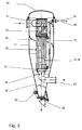
- the Fig. 3 shows the detailed structure of a cyclone separator 12 according to the invention with the built-in fine dust filter 13 and the gas cooler 14th
- the apparatus unit consists of the cyclone housing 11 for the dedusting, the gas cooler 14, which is designed as a water-cooled shell-and-tube heat exchanger 19, and the fine dust filter 13 for the fine filtration of the exhaust gas.
- the fine dust filter 13 and the tube bundle heat exchanger 19 are interconnected and arranged concentrically in the vacuum-tight cyclone housing 11 such that the lower part 21 of the tube bundle heat exchanger 19 is conical and loosely seated in the conical counter-funnel 18 of the gas outlet nozzle 23 of the cyclone housing 11.
- the fine dust filter 13 can also be removed without the gas cooler 14 or the tube bundle heat exchanger 19.
- a vacuum-tight cap 28 preferably with pneumatic or hydraulic drive installed.
- a vibrator 30 is mounted electric or pneumatic drive, which is preferably located on the cyclone cone 27.
- the function of the cyclone separator 12 is as follows: The dust-laden hot gas is guided by the suction force of the vacuum generator 16 into the tangentially arranged inlet connection 31 of the cyclone separator 12. Due to the high inlet velocity and the resulting rotary motion, the centrifugal forces act on the larger particles of the hot gas, so that the particles are collected in a known manner in the cyclone cone 27. Screw-shaped baffles 32 on the inner wall of the cyclone housing 11 support the deposition of the particles. Due to the initially perpendicularly directed gas flow, a partial cooling of the gas through the water-cooled jacket 33 of the shell-and-tube heat exchanger 19 is already achieved.
- the entire gas volume with the residual dusts is sucked through the fine dust filter 13 and then through the tube bundle heat exchanger 19.
- the fine dust filter 13 preferably consists of closely meshed micro-stainless steel filter mats and is matched to the fine particle size.
- pneumatic impulse shocks preferably by means of inert gas from the Inside the fine dust filter 13 is provided in the direction of the cyclone housing 11, which promote the dust down into the cyclone cone 27.
- the water-cooled shell-and-tube heat exchanger 19 is designed according to the crossflow principle - gas through the pipes, water around the pipes.
- the cooled and shrunk in volume clean gas leaves the cyclone 12 in the direction of the vacuum generator 16 through the gas outlet nozzle 23.
- it may be provided to rotate the particulate matter filter 13 and the gas cooler 14 in the cyclone housing 18 by 180 °.
- the flooding of the entire system usually takes place with atmospheric air.
- the high proportion of fines can lead to explosion due to O 2 enrichment on the grain surface for spontaneous combustion or in concatenation with other operating conditions, eg spark with sufficient capacity. Therefore, at the end of the process, the interior of the cyclone separator 12 is preferably separated from the rest of the system volume and flooded with inert gas.
Landscapes
- Chemical & Material Sciences (AREA)
- Chemical Kinetics & Catalysis (AREA)
- Cyclones (AREA)
- Separating Particles In Gases By Inertia (AREA)
- Waste-Gas Treatment And Other Accessory Devices For Furnaces (AREA)
- Filtering Materials (AREA)
- Treatment Of Steel In Its Molten State (AREA)
Description
- Die Erfindung betrifft ein Verfahren zur Abgasreinigung nach dem Oberbegriff des Anspruchs 1. Ferner betrifft die Erfindung eine Anordnung zur Abgasreinigung nach einem erfindungsgemäßen Verfahren.
- Ein Verfahren nach dem Oberbegriff des Anspruchs 1 ist aus der
DE 556 179 C bekannt. Das aus der genannten Schrift bekannte Verfahren weist eine Anordnung zur Abgasreinigung mit einem Zyklonabscheider, einem Feinstaubfilter sowie einem Kühler auf. Bei dem bekannten Verfahren werden die zu reinigenden Abgase zunächst durch einen Wärmetauscher geführt, wo sie unter Wärmeabgabe gekühlt werden. Anschließend gelangen die Abgase in einen Zyklonabscheider, wo eine Grobabscheidung von Partikeln stattfindet. Zuletzt gelangt das von den Grobpartikeln befreite Abgas in einen Feinstaubfilter, wo eine Abscheidung von Feinstaub stattfindet. Nachteilig dabei ist, dass das Abgas vor der Abscheidung der Grobpartikel und der Feinpartikel in dem Zyklonabscheider und dem Feinstaubfilter gekühlt wird. Dadurch ist eine relative große Kühleinrichtung erforderlich, da das gesamte Volumen des Abgases herabgekühlt wird. - Bei den sogenannten sekundärmetallurgischen Prozessen bei der Stahlherstellung, insbesondere bei den Sauerstoff-Blasprozessen, wird der flüssige Stahl unter Vakuum behandelt. Die sogenannte Stahlentgasung sowie die Herstellung von Stählen mit niedrigem C-Gehalt durch sogenanntes Aufblasen von Sauerstoff sind Behandlungsvarianten, die aus dem Stand der Technik bekannt sind und weltweite Anwendung finden.
- Die Anlagen für die Durchführung der vorgenannten Verfahren bestehen im Wesentlichen aus zwei Kernkomponenten, dem sogenannten Rezipienten einerseits, in dem Gießpfannen mit flüssigem Stahl mit einer Kapazität bis über 300t unter Vakuum behandelt werden, und andererseits dem Vakuumerzeuger, der über eine Saugleitung mit dem Rezipienten verbunden ist. Bei den unter vermindertem Druck zwischen 200mbar und 0,6mbar absolut ablaufenden Prozessen werden gelöste Gase wie auch Reaktionsgase freigesetzt, welche von dem Vakuumerzeuger, unter Aufrechterhaltung des jeweiligen absoluten Arbeitsdruckes, abgesaugt werden. Hierbei werden mitgerissene oder durch Verdampfung und Kondensation entstandene metallische und nichtmetallische Staubpartikel im Abgasstrom mittransportiert. Je nach Verfahren kann der Staub bei einer Abgastemperatur bis zu 500 °C und einer Korngröße von 0,5µm bis ≥ 100µm bei einem Massenanfall von 3kg bis 4kg Staub je Tonne Flüssigstahl betragen.
- Für die hohen Saugvolumina bei niedrigem Saugdruck sind heute zwei verschiedenartige Vakuumpumpensysteme im Einsatz: Zum Einen sind es die weitgehend staubunempfindlichen Dampfstrahl-Ejektorpumpen, die einen höheren Energiebedarf haben, und zum Anderen die staubanfälligen mechanischen Vakuumpumpen.
- Bei Anlagen, bei welchen das Vakuum mittels mehrstufiger Dampfstrahl-Ejektorpumpen erzeugt wird, stellt die Staubbelastung im Abgas keine direkte Funktionsbeeinträchtigung der Ejektorpumpen dar. Die Abgase werden hier über mehrstufige Ejektoren auf Atmosphärendruck komprimiert, wobei die im Abgas enthaltenen Stäube sich zu ca. 5% bis 10% an den Wandungen der Rohrleitungen und Ejektoren anlagern und die restlichen 90% bis 95% vom Kreislauf-Kühlwasser in den Einspritzkondensatoren ausgewaschen und ausgetragen werden. Hohe Aufwendungen für arbeitsintensive manuelle Reinigungsarbeiten sowie für die Reinigung des mit den Staubpartikeln verunreinigten Kreislaufwassers sind hier jedoch als nachteilhaft anzusehen. Die Vakuumerzeugung durch Dampfstrahler ist außerdem noch gekennzeichnet durch einen hohen Dampfverbrauch, der vor Ort in einem Dampferzeuger hoher Leistung erzeugt werden muss, was zusätzliche Kosten verursacht.
- Wesentlich energiesparender ist dagegen der Betrieb von mechanischen Vakuumpumpen, die allerdings empfindlich gegen hohe Temperaturen und den Staub im angesaugten Gas sind. Daher ist für mechanische Vakuumpumpen grundsätzlich immer eine Gas/Staubtrennung und Gaskühlung zwischen dem Rezipienten und der Vakuumpumpe vorgesehen. In den bisher installierten Anlagen unter Verwendung von mechanischen Vakuumpumpen wird das abgesaugte Gas vor dem Eintritt in die Vakuumpumpen zunächst durch einen Zyklon geführt, in welchem eine Abscheidung von groben Staubteilchen erfolgt. Anschließend wird das Gas zur Kühlung in einen Gaskühler geleitet, und gelangt von dort durch einen Feinstaubfilter, der dazu dient, kleinste Staubteilchen ab- bzw. auszuscheiden.
- Die oben angeführten Komponenten einer Vorrichtung unter Verwendung von mechanischen Vakuumpumpen werden hintereinander in die Vakuumleitung eingebaut, was abgesehen vom Platzbedarf eine entsprechende Länge der Vakuumleitung zur Folge hat. Dies widerspricht der Forderung nach einer möglichst kurzen Leitung zwischen dem Rezipienten und dem Vakuumpumpensatz, um eine größtmögliche Effektivität bei der Vakuumerzeugung im Rezipienten zu erzielen.
- Ausgehend von dem Eingangs genannten Stand der Technik (
DE 556 179 C ) liegt der Erfindung die Aufgabe zugrunde, ein Verfahren zur Abgasreinigung derart weiterzubilden, dass die zur Kühlung des Abgases verwendete Kühleinrichtung möglichst einfach bzw. kompakt aufgebaut werden kann. Diese Aufgabe wird erfindungsgemäß bei einem Verfahren zur Abgasreinigung mit den Merkmalen des Anspruchs 1 gelöst. Insbesondere besteht der Kerngedanke der Erfindung darin, dass das erfindungsgemäße Verfahren drei Verfahrensschritte aufweist, die hintereinander derart ausgeführt werden, wobei in einem ersten Verfahrensschritt eine Grobabscheidung von Partikeln aus dem Abgas, in einem zweiten Schritt eine Feinstaubabscheidung von Partikeln aus dem Abgas und in einem dritten Schritt eine Gaskühlung in einem Zyklonabscheider stattfindet. Wesentlich dabei ist, dass das Abgas nach erfolgter Grobreinigung direkt über einen im Zyklonenabscheider eingebauten Feinstaubfilter und anschließend durch einen an den Feinstaubfilter sich anschließenden Gaskühler geführt wird. Dadurch ist es, im Gegensatz zum genannten Stand der Technik nicht erforderlich, die im Abgas befindlichen Grob- und Feinpartikel zu kühlen. Dadurch, dass alle erforderlichen Verfahrensschritte zur Entstaubung wie die Vorentstaubung, die Feinfilterung und die Gaskühlung in einem einzigen, vakuumdichten kompakten Zyklonabscheider mit eingebautem Feinstaubfilter mit angeschlossenem Gaskühler durchzuführen, wobei das in den Zyklon eintretende Rohgas durch schraubenartige Leitbleche in eine rotierende Bewegung gezwungen wird, wodurch einerseits die Grobstaubabscheidung begünstigt wird, und andererseits eine Vorkühlung des Gasstroms am Außenmantel des eingebauten Wärmetauschers bewirkt wird. Anschließend wird das Gas durch einen mit Mikro-Edelstahlfiltermatten bestückten Feinstaubfilter und den daran angeschlossenen wassergekühlten Gaskühler und über den Gastrichter in die Vakuumgasleitung zu den Vakuumpumpen geführt. Ganz besonders vorteilhaft ist es dabei, dass durch die kompakte Bauweise der Vorrichtung die Länge der Vakuumleitung erheblich verkürzt, wodurch der Druckverlust niedrig gehalten werden kann. - Vorteilhafte Weiterbildungen sind in den Unteransprüchen angeführt.
- Die zusammengebaute Filter-Kühleinheit stützt sich lose auf den Abgastrichter der Vorrichtung ab, sodass ein einfacher Ausbau der Komponenten aus dem Gehäuse der Vorrichtung nach oben möglich ist, da diese im Wesentlichen nur angehoben werden müssen.
- Der Zyklon verfügt am unteren trichterförmigen Ende über eine vakuumdichte Staubklappe, über die der anfallende Grob- und Feinstaub ausgetragen werden kann.
- Der Feinfilter wird pneumatisch mittels Inertgas gereinigt. Unabhängig davon ist eine getrennte Flutung des Zykloninnenraumes mittels Inertgas vorteilhaft.
- Weitere Vorteile, Merkmale und Einzelheiten der Erfindung ergeben sich aus der nachfolgenden Beschreibung eines bevorzugten Ausführungsbeispiels der Erfindung sowie anhand der Zeichnung. Diese zeigt in:
- Fig. 1
- eine Anordnung zur Abgasreinigung nach dem Stand der Technik in einer Prinzipdarstellung,
- Fig. 2
- eine erfindungsgemäße Anordnung zur Abgasreinigung, ebenfalls in einer Prinzipdarstellung und
- Fig. 3
- einen bei der Anordnung gemäß der
Fig. 2 verwendeten Zyklonabscheider in einem Längsschnitt. - Die
Fig. 1 zeigt eine dem derzeitigen Stand der Technik entsprechende Vorrichtung zur Abgasreinigung bei der Stahlherstellung mit einem in eine Saugleitung 2 zwischen einem Rezipienten 1 und einem Vakuumerzeuger 3 eingebauten Zyklonabscheider 4 zur Grobentstaubung, einem getrennt angeordneten Gaskühler 5 und einem nachfolgend angeordneten Feinfilter 6. Der Feinfilter 6 ist hier nach dem Gaskühler 5 angeordnet, da diese vielfach mit Tuchfiltersäcken bestückt sind, die vor zu hohen Gastemperaturen geschützt werden müssen. - Die
Fig. 2 zeigt eine erfindungsgemäße Anordnung 10 zur Abgasentstaubung mit einem in dem Zyklongehäuse 11 eines Zyklonabscheiders 12 integrierten Feinstaubfilter 13 und einem Gaskühler 14. Der Zyklonabscheider 12 ist zwischen einem Rezipienten 15 und einem Vakuumerzeuger 16 in einer Vakuumleitung 17 angeordnet, wobei der Vakuumerzeuger 16 beliebiger Bauart sein kann. - Die
Fig. 3 zeigt den detaillierten Aufbau eines erfindungsgemäßen Zyklonabscheiders 12 mit dem eingebautem Feinstaubfilter 13 und dem Gaskühler 14. - Die Apparateeinheit besteht aus dem Zyklongehäuse 11 für die Vorentstaubung, dem Gaskühler 14, der als wassergekühlter Rohrbündelwärmetauscher 19 ausgebildet ist, und dem Feinstaubfilter 13 für die Feinfilterung des Abgases.
- Der Feinstaubfilter 13 und der Rohrbündelwärmetauscher 19 sind miteinander verbunden und konzentrisch im vakuumdichten Zyklongehäuse 11 derart angeordnet, dass der untere Teil 21 des Rohrbündelwärmetauschers 19 konisch ausgebildet und im konischen Gegentrichter 18 des Gasaustrittstutzens 23 des Zyklongehäuses 11 lose aufsitzt. Hierdurch wird nach dem Öffnen des Deckels 24 des Zyklongehäuses 11 und nach dem Lösen der Wasserein- und Austrittsverbindungen 25 und 26 ein einfacher Ausbau für Wartungszwecke gewährleistet. Je nach Erfordernis kann auch der Feinstaubfilter 13 ohne den Gaskühler 14 bzw. den Rohrbündelwärmetauscher 19 ausgebaut werden.
- Für den Staubaustrag ist am unteren Zyklonkonus 27 eine vakuumdichte Verschlusskappe 28, vorzugsweise mit pneumatischem oder hydraulischem Antrieb, installiert. Zur Unterstützung des Staubaustrags aus dem Zyklonabscheider 12 ist ein Rüttler 30 elektrischem oder pneumatischem Antrieb angebaut, der sich vorzugsweise am Zyklonkonus 27 befindet.
- Die Funktion des Zyklonabscheiders 12 ist wie folgt: Das staubbeladene Heißgas wird durch die Saugkraft des Vakuumerzeugers 16 in den tangential angeordneten Eintrittsstutzen 31 des Zyklonabscheiders 12 geführt. Durch die hohe Eintrittsgeschwindigkeit und die dadurch einsetzende Drehbewegung wirken die Zentrifugalkräfte auf die größeren Partikel des Heißgases, so dass die Partikel in bekannter Weise im Zyklonkonus 27 aufgefangen werden. Schraubenartig geformte Leitbleche 32 an der Innenwand des Zyklongehäuses 11 unterstützen den Abscheidevorgang der Partikel. Durch den zunächst senkrecht gerichteten Gasstrom wird bereits eine Teilkühlung des Gases durch den wassergekühlten Mantel 33 des Rohrbündelwärmetauschers 19 erreicht.
- Das gesamte Gasvolumen mit den Reststäuben wird über den Feinstaubfilter 13 und anschließend durch den Rohrbündelwärmetauscher 19 gesaugt. Der Feinstaubfilter 13 besteht vorzugsweise aus engmaschigen Micro-Edelstahlfiltermatten und ist auf die Feinkornpartikelgröße abgestimmt. Für die Reinigung des Feinstaubfilters 13 sind bei Anlagenstillstand pneumatische Impulsstöße, vorzugsweise mittels Inertgas, vom Inneren des Feinstaubfilters 13 in Richtung des Zyklongehäuses 11 vorgesehen, die den Staub nach unten in den Zyklonkonus 27 fördern.
- Der wassergekühlte Rohrbündelwärmetauscher 19 ist nach dem Kreuzstromprinzip - Gas durch die Rohre, Wasser um die Rohre - ausgebildet. Das gekühlte und im Volumen geschrumpfte Reingas verlässt den Zyklonabscheider 12 in Richtung des Vakuumerzeugers 16 durch den Gasaustrittsstutzen 23. Je nach Staubkorngrößenverteilung kann es vorgesehen sein, den Feinstaubfilter 13 und den Gaskühler 14 im Zyklongehäuse 18 um 180 ° zu drehen.
- Bei Prozeßende erfolgt die Flutung des gesamten Systems üblicherweise mit atmosphärischer Luft. Der hohe Feinkornanteil kann aufgrund einer O2-Anreicherung an der Kornoberfläche zur Selbstentzündung oder in Verkettung mit anderen Betriebszuständen, z.B. Zündfunke mit ausreichender Kapazität, zur Explosion führen. Daher wird bei Prozeßende der Innenraum des Zyklonabscheiders 12 vorzugsweise vom übrigen Anlagenvolumen getrennt und mit Inertgas geflutet.
-
- 1
- Rezipient
- 2
- Saugleitung
- 3
- Vakuumerzeuger
- 4
- Zyklonabscheider
- 5
- Gaskühler
- 6
- Feinfilter
- 10
- Anordnung
- 11
- Zyklongehäuse
- 12
- Zyklonabscheider
- 13
- Feinstaubfilter
- 14
- Gaskühler
- 15
- Rezipient
- 16
- Vakuumerzeuger
- 17
- Vakuumleitung
- 18
- Gegentrichter
- 19
- Rohrbündelwärmetauscher
- 21
- unterer Teil
- 23
- Gasaustrittstutzen
- 24
- Deckel
- 25
- Wassereintrittsverbindung
- 26
- Wasseraustrittsverbindung
- 27
- Zyklonkonus
- 28
- Verschlussklappe
- 30
- Rüttler
- 31
- Eintrittsstutzen
- 32
- Leitblech
- 33
- Mantel
Claims (10)
- Verfahren zur Abgasreinigung bei Entgasungsanlagen unter Verwendung einer Einrichtung (16) zur Erzeugung eines Unterdrucks, insbesondere mittels Dampfstrahl-Ejektorpumpen oder mechanischen Vakuumpumpen,
dadurch gekennzeichnet,
dass das von einem Rezipienten (15) kommende Abgas in einen Zyklonabscheider (12) geleitet wird, und dass die Verfahrensschritte Grobabscheidung von Partikeln aus dem Abgas und Feinstaubabscheidung von Partikeln aus dem Abgas sowie Gaskühlung in dem Zyklonabscheider (12) hintereinander in der Weise durchgeführt werden, dass das Abgas nach erfolgter Grobreinigung direkt über einen im Zyklonabscheider (12) eingebauten Feinstaubfilter (13) und anschließend durch einen an den Feinstaubfilter (13) sich anschließenden Gaskühler (14) in eine mit der Einrichtung (16) zur Erzeugung eines Unterdrucks verbundene Saugleitung (2) zur Einrichtung (16) geführt wird. - Verfahren nach Anspruch 1, dadurch gekennzeichnet, dass aus dem in den Zyklonabscheider (12) eintretenden Abgas durch eine durch Leitbleche (32) bewirkte, insbesondere schraubenförmige Bewegung grobe Staubpartikel ausgeschieden werden, und dass das Abgas zur Vorkühlung eine Außenwand (33) des als Wärmetauscher (19) ausgebildeten Gaskühlers (14) umströmt.
- Anordnung (10) zur Durchführung des Verfahrens nach Anspruch 1 oder 2, dadurch gekennzeichnet, dass die Anordnung (10) einen Zyklonabscheider (12) mit einem Zyklongehäuse (11) umfasst, wobei in dem Zyklongehäuse (11) ein Feinstaubfilter (13) und ein Gaskühler (14) angeordnet sind, und wobei in den Zyklonabscheider (12) eintretendes Abgas zwangsweise über den Feinstaubfilter (13) und den Gaskühler (14) zu einer mit der Einrichtung (16) verbundenen Saugleitung (2) führbar ist.
- Anordnung nach Anspruch 3, dadurch gekennzeichnet, dass der Feinstaubfilter (13) einen aus dem Zyklongehäuse (11) herausragenden Gasaustrittsstutzen (23) aufweist, und dass das Zyklongehäuse (11) eine Austragseinrichtung in Form einer Verschlussklappe (28) für Partikel aufweist.
- Anordnung nach Anspruch 4, dadurch gekennzeichnet, dass die Verschlussklappe (28) an Grund eines konusförmigen Bereichs (17) des Zyklongehäuses (11) angeordnet ist, und dass der Bereich (17) mit einer Rütteleinrichtung (30) zum Lösen von Partikeln im Zyklongehäuse (11) gekoppelt ist.
- Anordnung nach einem der Ansprüche 3 bis 5, dadurch gekennzeichnet, dass im Zyklongehäuse (11) wenigstens ein vorzugsweise schraubenförmiges Leitblech (32) zur Abgasführung angebracht sind.
- Anordnung nach Anspruch 6, dadurch gekennzeichnet, dass das wenigstens eine Leitblech (32) das Abgas auf die Außenwand (33) des Gaskühlers (13) leitet.
- Anordnung nach einem der Ansprüche 3 bis 7, dadurch gekennzeichnet, dass der in dem Zyklongehäuse (11) eingebaute Feinstaubfilter (13) und der Gaskühler (14) miteinander verbunden sind und lose auf einem Gehäuseabschnitt (18) des Gasaustrittsstutzens (23) aufsitzen.
- Anordnung nach einem der Ansprüche 3 bis 8, dadurch gekennzeichnet, dass der Feinstaubfilter (13) Mikro-Edelstahlfiltermatten aufweist und zum pneumatischen Reinigen mittels Inertgas eingerichtet ist.
- Anordnung nach einem der Ansprüche 4 bis 9, dadurch gekennzeichnet, dass die Staubklappe (13) das Zyklongehäuse (11) vakuumdicht abdichtet.
Applications Claiming Priority (2)
| Application Number | Priority Date | Filing Date | Title |
|---|---|---|---|
| ATA71/2012A AT511613B1 (de) | 2012-01-24 | 2012-01-24 | Verfahren und anlage zur abgasreinigung bei vakuum-stahlbehandlungsprozessen |
| PCT/EP2013/051224 WO2013110647A1 (de) | 2012-01-24 | 2013-01-23 | Verfahren und anordnung zur abgasreinigung bei vakuum-stahlbehandlungsprozessen |
Publications (2)
| Publication Number | Publication Date |
|---|---|
| EP2806976A1 EP2806976A1 (de) | 2014-12-03 |
| EP2806976B1 true EP2806976B1 (de) | 2015-08-19 |
Family
ID=47667376
Family Applications (1)
| Application Number | Title | Priority Date | Filing Date |
|---|---|---|---|
| EP13704886.4A Not-in-force EP2806976B1 (de) | 2012-01-24 | 2013-01-23 | Verfahren und anordnung zur abgasreinigung bei vakuum-stahlbehandlungsprozessen |
Country Status (6)
| Country | Link |
|---|---|
| US (1) | US20150033944A1 (de) |
| EP (1) | EP2806976B1 (de) |
| JP (1) | JP2015511172A (de) |
| CN (1) | CN104144750A (de) |
| AT (1) | AT511613B1 (de) |
| WO (1) | WO2013110647A1 (de) |
Cited By (1)
| Publication number | Priority date | Publication date | Assignee | Title |
|---|---|---|---|---|
| CN106422602A (zh) * | 2016-11-30 | 2017-02-22 | 郑州中拓知识产权代理有限公司 | 一种循环式工业废气处理设备 |
Families Citing this family (24)
| Publication number | Priority date | Publication date | Assignee | Title |
|---|---|---|---|---|
| GB0816310D0 (en) | 2008-09-05 | 2008-10-15 | Mtt Technologies Ltd | Filter assembly |
| FI123720B (fi) * | 2011-10-17 | 2013-10-15 | Maricap Oy | Pneumaattisen materiaalinsiirtojärjestelmän erotuslaite ja menetelmä |
| JP2017538038A (ja) * | 2014-11-21 | 2017-12-21 | レニショウ パブリック リミテッド カンパニーRenishaw Public Limited Company | 付加製造装置および方法 |
| CN105289259A (zh) * | 2015-11-18 | 2016-02-03 | 华文蔚 | 一种用于焚烧炉废气处理的装置 |
| CN108369217A (zh) * | 2015-12-07 | 2018-08-03 | 株式会社堀场制作所 | 分析装置 |
| CN106039894B (zh) * | 2016-05-26 | 2018-09-25 | 宜宾天原集团股份有限公司 | 可回收三氯化铁的氯化炉出炉气气固分离系统 |
| CN106621630B (zh) * | 2016-12-27 | 2019-04-12 | 浙江新格有色金属有限公司 | 一种工业生产废气处理系统 |
| CN107234010A (zh) * | 2017-06-20 | 2017-10-10 | 大连理工大学 | 自引射循环回流超音速旋流分离器及其分离方法 |
| DE102017212164A1 (de) * | 2017-07-17 | 2019-01-17 | Robert Bosch Gmbh | Verbindungsvorrichtung für ein Abgasmesssystem |
| JP2019205968A (ja) * | 2018-05-29 | 2019-12-05 | 加昌國際有限公司 | 濾過装置 |
| CN109266810A (zh) * | 2018-10-09 | 2019-01-25 | 江苏联峰能源装备有限公司 | 一种新型vd机械泵真空炉除尘装置 |
| KR20210080475A (ko) * | 2018-10-24 | 2021-06-30 | 퍼킨엘머 헬스 사이언스 캐나다 인코포레이티드 | 입자 필터 및 이를 포함하는 시스템 |
| CN110846084B (zh) * | 2019-11-29 | 2024-03-12 | 北京航天迈未科技有限公司 | 一种粉尘分离回收设备及方法 |
| EP4491947A3 (de) * | 2020-03-06 | 2025-03-19 | Metso Metals Oy | Zyklonabscheideranordnung |
| CN111589259A (zh) * | 2020-06-22 | 2020-08-28 | 无锡红旗除尘设备有限公司 | 具备防爆燃和防滤料烧烫的固/气分离装置和工作方法 |
| TWI732645B (zh) * | 2020-08-05 | 2021-07-01 | 國立臺灣科技大學 | 分離冷卻裝置及應用其的燃料化系統 |
| KR102598003B1 (ko) * | 2021-08-23 | 2023-11-06 | 삼미금속 주식회사 | 금속 산 처리시 발생 되는 유독 가스 제거장치 및 그 장치를 이용한 유독 가스 제거 방법 |
| CN113975921B (zh) * | 2021-10-26 | 2023-04-25 | 厦门双瑞风电科技有限公司 | 一种风电叶片灌注用真空过滤系统 |
| CN114748943A (zh) * | 2022-03-24 | 2022-07-15 | 广东美的白色家电技术创新中心有限公司 | 一种分离器、具有分离器的负压装置和压力锅 |
| CN115371455B (zh) * | 2022-07-21 | 2023-03-10 | 瑞燃(上海)环境工程技术有限公司 | 一种用于液氮换热设备的保温结构及保温方法 |
| CN115814534A (zh) * | 2022-11-16 | 2023-03-21 | 深圳市成德机械有限公司 | 一种造纸废气处理系统 |
| DE102023131483A1 (de) * | 2023-11-13 | 2025-05-15 | MAFAC - E. Schwarz GmbH & Co. KG | Vorrichtung und verfahren zur entfeuchtung von gasen und system mit einer solchen vorricthung |
| CN117770988B (zh) * | 2024-01-19 | 2024-09-03 | 安徽省天翔医疗股份有限公司 | 一种集成式医用真空负压机 |
| CN118758069B (zh) * | 2024-06-21 | 2025-10-28 | 江西江冶实业有限公司 | 一种铜排生产过程中的废热回收与利用设备 |
Family Cites Families (55)
| Publication number | Priority date | Publication date | Assignee | Title |
|---|---|---|---|---|
| DE556179C (de) * | 1932-08-03 | Babcock & Wilcox Dampfkessel W | Rauchgas-Entstaubungsanlage | |
| US3013628A (en) * | 1959-10-12 | 1961-12-19 | Morris B Jacobs | Device for abatement of air pollution |
| US3146998A (en) * | 1960-10-22 | 1964-09-01 | Kloeckner Humboldt Deutz Ag | Method and apparatus for preheating of fine-grain material |
| US3327456A (en) * | 1964-04-30 | 1967-06-27 | Exxon Research Engineering Co | High temperature cyclone |
| US3470678A (en) * | 1967-06-20 | 1969-10-07 | Exxon Research Engineering Co | Cyclone separator for high temperature operations |
| US3780502A (en) * | 1971-01-25 | 1973-12-25 | Nat Foundry Equip Co Inc | Collector apparatus |
| JPS4853670U (de) * | 1971-10-18 | 1973-07-11 | ||
| JPS5333250Y2 (de) * | 1972-05-17 | 1978-08-16 | ||
| JPS5491602A (en) * | 1977-12-28 | 1979-07-20 | Hirakawa Tekkosho | Cyclone type waste heat boiler |
| SE434865B (sv) * | 1979-08-22 | 1984-08-20 | Atlas Copco Ab | Sett och anordning for bindning av borrdamm |
| US4913711A (en) * | 1982-07-16 | 1990-04-03 | Foster Wheeler Energy Corporation | Spiral coil cool wall construction for high temperature cylindrical furnaces, vessels, cyclones, etc. |
| JPS60222157A (ja) * | 1984-04-20 | 1985-11-06 | Mitsui Toatsu Chem Inc | サイクロンの詰り防止方法 |
| DE3424170A1 (de) * | 1984-06-30 | 1986-02-27 | Metallgesellschaft Ag, 6000 Frankfurt | Klinkerkuehler mit entstaubungsvorrichtung in einem verfahren zur zementherstellung |
| US4615715A (en) * | 1985-03-15 | 1986-10-07 | Foster Wheeler Energy Corporation | Water-cooled cyclone separator |
| AT383289B (de) * | 1985-05-28 | 1987-06-10 | Voest Alpine Ag | Einrichtung zum abtrennen von staub aus gasen |
| EP0262274A1 (de) * | 1986-09-22 | 1988-04-06 | Emile Percevaut | Rekuperator von Wärme aus Rauchgasen aus verschiedenen Öfen mit Reinigung von diesen Gasen |
| US4845334A (en) * | 1988-01-26 | 1989-07-04 | Oregon Metallurgical Corporation | Plasma furnace inert gas recycling system and process |
| DK163745C (da) * | 1988-03-08 | 1992-09-07 | Smidth & Co As F L | Varmeveksler |
| US5028318A (en) * | 1989-04-19 | 1991-07-02 | Aeroquip Corporation | Cyclonic system for separating debris particles from fluids |
| GB9116020D0 (en) * | 1991-07-25 | 1991-09-11 | Serck Baker Ltd | Separator |
| JPH07328384A (ja) * | 1994-06-01 | 1995-12-19 | Babcock Hitachi Kk | ごみ焼却設備における排ガス処理方法 |
| US6042628A (en) * | 1996-11-12 | 2000-03-28 | Toyo Gijutsu Kogyo Co., Ltd. | Cyclone type dust collector |
| TW410237B (en) * | 1996-12-25 | 2000-11-01 | Nippon Steel Corp | Vacuum, pressure reduction refining method and the vacuum, pressure reduction refining equipment |
| US6056796A (en) * | 1998-02-09 | 2000-05-02 | The United States Of America As Represented By The United States Department Of Energy | Rigid porous filter |
| JP3781914B2 (ja) * | 1999-03-31 | 2006-06-07 | アマノ株式会社 | 集塵装置 |
| EP1153662B1 (de) * | 2000-05-12 | 2004-07-14 | KHD Humboldt Wedag AG | Hitze- und verschleissbeanspruchtes Einbauelement, insbesondere Segment eines Zyklontauchrohres |
| US8578628B2 (en) * | 2000-08-29 | 2013-11-12 | Rich Technology Solutions Limited | Milling and drying apparatus incorporating a cyclone |
| US6500243B2 (en) * | 2001-02-02 | 2002-12-31 | Ingersoll-Rand Company | Compressor system including a separator tank with a separator element positioned therein |
| JP4215489B2 (ja) * | 2001-11-27 | 2009-01-28 | 株式会社industria | 遠心分離装置 |
| WO2003084642A1 (en) * | 2002-04-04 | 2003-10-16 | Kabushiki Kaisha Yms | Dust collector |
| US6793013B2 (en) * | 2003-01-09 | 2004-09-21 | Foster Wheeler Energy Corporation | Polygonal heat exchange chamber including a tapered portion lined with water tube panels and method of lining a tapered portion of a polygonal heat exchange chamber with such panels |
| JP2005058847A (ja) * | 2003-08-08 | 2005-03-10 | Kyoshin Kogyo Co Ltd | 水・空気内の異物除去と浄化殺菌装置 |
| AU2005289143B2 (en) * | 2004-09-27 | 2010-07-01 | Durr Dental Ag | Dryer unit for compressed air and other gaseous media |
| JP4460993B2 (ja) * | 2004-10-22 | 2010-05-12 | 祺人 西岡 | 熱交換器付き集塵サイクロン |
| DE102004054628A1 (de) * | 2004-11-11 | 2006-05-18 | Basell Polyolefine Gmbh | Vorrichtung zur Gasphasenpolymerisation von Olefinen, insbesondere Ethylen |
| US20060157899A1 (en) * | 2005-01-15 | 2006-07-20 | Lew Holdings, Llc | Single vessel blast furnace and steel making/gasifying apparatus and process |
| KR20070078679A (ko) * | 2006-01-27 | 2007-08-01 | 삼성광주전자 주식회사 | 집진장치 |
| US7594941B2 (en) * | 2006-08-23 | 2009-09-29 | University Of New Brunswick | Rotary gas cyclone separator |
| US7682413B2 (en) * | 2006-10-16 | 2010-03-23 | Deere & Company | Air precleaner arrangement for an internal combustion engine comprising two cyclone filters |
| US7662199B2 (en) * | 2007-03-07 | 2010-02-16 | Tennant Company | Cyclonic filter for surface maintenance machine |
| FI120188B (fi) * | 2007-10-08 | 2009-07-31 | Foster Wheeler Energia Oy | Keskipakoerotinjärjestely |
| US7931740B2 (en) * | 2008-06-20 | 2011-04-26 | The Boeing Company | Cyclone separator |
| US20110140294A1 (en) * | 2008-06-27 | 2011-06-16 | Brian Pyke | Sulphur Granulation Apparatus and Process |
| BRPI0803051B1 (pt) * | 2008-06-30 | 2019-01-15 | Petróleo Brasileiro S/A - Petrobras | separador ciclônico de suspensão gás-sólido e método de separação |
| CN201239671Y (zh) * | 2008-08-11 | 2009-05-20 | 宁夏三友环保设备制造有限公司 | 风冷旋风分离器 |
| KR101610988B1 (ko) * | 2009-01-22 | 2016-04-08 | 타이헤이요 세멘트 가부시키가이샤 | 중금속 제거장치 및 시멘트 제조시스템 |
| CN102458667B (zh) * | 2009-04-06 | 2015-05-06 | 伊安·格雷 | 气液固分离器 |
| CN201493188U (zh) * | 2009-05-12 | 2010-06-02 | 宁夏三友环保设备制造有限公司 | 组合型旋风分离式沉降冷却器 |
| JP5483317B2 (ja) * | 2009-08-12 | 2014-05-07 | 大同特殊鋼株式会社 | 精錬装置の排気方法および排気装置 |
| DE102009050087B4 (de) * | 2009-10-20 | 2011-12-22 | Areva Np Gmbh | Zyklonabscheider zur Phasenseparation eines Mehrphasen-Fluidstroms, Dampfturbinenanlage mit einem Zyklonabscheider und zugehöriges Betriebsverfahren |
| CA2698176C (en) * | 2010-03-30 | 2013-03-12 | Guy Prud'homme | Energy recuperating filtration apparatus |
| US8251227B2 (en) * | 2010-04-16 | 2012-08-28 | Kellogg Brown & Root Llc | Methods and apparatus for separating particulates from a particulate-fluid mixture |
| US8157895B2 (en) * | 2010-05-04 | 2012-04-17 | Kellogg Brown & Root Llc | System for reducing head space in a pressure cyclone |
| EA025983B1 (ru) * | 2011-09-19 | 2017-02-28 | Роквул Интернэшнл А/С | Регулирующий клапанный узел и способ подачи зернистого материала через такой регулирующий клапанный узел |
| SG11201408506VA (en) * | 2012-07-06 | 2015-03-30 | Practical Analyzer Solutions Pte Ltd | Centrifugal cyclone separator |
-
2012
- 2012-01-24 AT ATA71/2012A patent/AT511613B1/de not_active IP Right Cessation
-
2013
- 2013-01-23 JP JP2014553698A patent/JP2015511172A/ja active Pending
- 2013-01-23 EP EP13704886.4A patent/EP2806976B1/de not_active Not-in-force
- 2013-01-23 WO PCT/EP2013/051224 patent/WO2013110647A1/de not_active Ceased
- 2013-01-23 US US14/373,643 patent/US20150033944A1/en not_active Abandoned
- 2013-01-23 CN CN201380005521.XA patent/CN104144750A/zh active Pending
Cited By (2)
| Publication number | Priority date | Publication date | Assignee | Title |
|---|---|---|---|---|
| CN106422602A (zh) * | 2016-11-30 | 2017-02-22 | 郑州中拓知识产权代理有限公司 | 一种循环式工业废气处理设备 |
| CN106422602B (zh) * | 2016-11-30 | 2018-10-02 | 安徽汇宇能源发展有限公司 | 一种循环式工业废气处理设备 |
Also Published As
| Publication number | Publication date |
|---|---|
| EP2806976A1 (de) | 2014-12-03 |
| AT511613A4 (de) | 2013-01-15 |
| JP2015511172A (ja) | 2015-04-16 |
| WO2013110647A1 (de) | 2013-08-01 |
| AT511613B1 (de) | 2013-01-15 |
| CN104144750A (zh) | 2014-11-12 |
| US20150033944A1 (en) | 2015-02-05 |
Similar Documents
| Publication | Publication Date | Title |
|---|---|---|
| AT511613B1 (de) | Verfahren und anlage zur abgasreinigung bei vakuum-stahlbehandlungsprozessen | |
| EP2832418B1 (de) | Reinigungsvorrichtung und deren Verwendung | |
| EP2137414B1 (de) | Filtervorrichtung | |
| DE202005003791U1 (de) | Apparatur zur Behandlung von partikelförmigem Gut | |
| DE102019121373B4 (de) | Abscheider mit partieller filtrierung | |
| DE102019132349A1 (de) | Verfahren zur intermittierenden Abreinigung eines Filters sowie Filtereinrichtung für eine Metall-Druckeinrichtung | |
| EP2122252A2 (de) | Verfahren und anlage zur nutzenergieerzeugung durch müllvergasung | |
| CN107686208A (zh) | 一种工业用污水处理装置 | |
| EP2352575A1 (de) | Verfahren zur reinigung eines rauchgases einer metallurgischen anlage und rauchgasreinigungsvorrichtung | |
| EP2595724A1 (de) | Verfahren zur reinigung eines mit stäuben beladenen gasstroms | |
| EP1034830B1 (de) | Vorrichtung zur Filtration eines mit Aerosolen beladenen Gasstromes | |
| EP2223033B1 (de) | Verfahren und vorrichtung zur grobabscheidung von feststoffpartikeln aus feststoffbeladenen gasen | |
| EP0720694B1 (de) | Absaugverfahren und vorrichtungen hierfür | |
| CN214974823U (zh) | 一种铁屑切削液分离装置 | |
| DE69904315T2 (de) | System zur trennung von verunreinigungen von strahlmitteln | |
| DE102009048062B4 (de) | Wärmeträgerölanlage sowie Verfahren zum Betreiben einer Wärmeträgerölanlage | |
| EP3025785B1 (de) | Vorrichtung und verfahren zum reinigen von rauchgas einer metallurgischen anlage | |
| CN210434144U (zh) | 连续螺旋式气液分离器件 | |
| DE102016121344B4 (de) | Filteranlage mit zentralem Vorabscheider und Verfahren zum Reinigen einer Filteranlage | |
| DE10126048A1 (de) | Vorrichtung zum Reinigen staubbeladener Rohgase | |
| DE652310C (de) | Vorrichtung zur Abscheidung von Staub aus Luft und Gasen, z. B. Huettengasen | |
| DE10144724B4 (de) | Verfahren und Vorrichtung zum Entsorgen von bei der Metallbearbeitung anfallenden Spänen sowie Staub | |
| EP1563889A2 (de) | Filternder Abscheider für partikelbelastete Gase | |
| EP3969144B1 (de) | Verfahren, primärabscheider in form eines hydrozyklons, sekundärabscheider und verwendung eines primärabscheiders zur aufreinigung eines mit partikeln einer erhitzten erdölfraktion verunreinigten kühlmittels, wie beispielsweise quenchfluid | |
| DE2747973B2 (de) | Kühlluftführungsgehäuse, das sich an ein Axialkühlluftgebläse anschlieBt |
Legal Events
| Date | Code | Title | Description |
|---|---|---|---|
| PUAI | Public reference made under article 153(3) epc to a published international application that has entered the european phase |
Free format text: ORIGINAL CODE: 0009012 |
|
| 17P | Request for examination filed |
Effective date: 20140702 |
|
| AK | Designated contracting states |
Kind code of ref document: A1 Designated state(s): AL AT BE BG CH CY CZ DE DK EE ES FI FR GB GR HR HU IE IS IT LI LT LU LV MC MK MT NL NO PL PT RO RS SE SI SK SM TR |
|
| GRAP | Despatch of communication of intention to grant a patent |
Free format text: ORIGINAL CODE: EPIDOSNIGR1 |
|
| DAX | Request for extension of the european patent (deleted) | ||
| INTG | Intention to grant announced |
Effective date: 20150415 |
|
| GRAS | Grant fee paid |
Free format text: ORIGINAL CODE: EPIDOSNIGR3 |
|
| GRAA | (expected) grant |
Free format text: ORIGINAL CODE: 0009210 |
|
| AK | Designated contracting states |
Kind code of ref document: B1 Designated state(s): AL AT BE BG CH CY CZ DE DK EE ES FI FR GB GR HR HU IE IS IT LI LT LU LV MC MK MT NL NO PL PT RO RS SE SI SK SM TR |
|
| REG | Reference to a national code |
Ref country code: GB Ref legal event code: FG4D Free format text: NOT ENGLISH |
|
| REG | Reference to a national code |
Ref country code: CH Ref legal event code: EP |
|
| REG | Reference to a national code |
Ref country code: IE Ref legal event code: FG4D Free format text: LANGUAGE OF EP DOCUMENT: GERMAN |
|
| REG | Reference to a national code |
Ref country code: AT Ref legal event code: REF Ref document number: 743405 Country of ref document: AT Kind code of ref document: T Effective date: 20150915 |
|
| REG | Reference to a national code |
Ref country code: DE Ref legal event code: R096 Ref document number: 502013001051 Country of ref document: DE |
|
| REG | Reference to a national code |
Ref country code: SE Ref legal event code: TRGR |
|
| REG | Reference to a national code |
Ref country code: LT Ref legal event code: MG4D |
|
| REG | Reference to a national code |
Ref country code: NL Ref legal event code: MP Effective date: 20150819 |
|
| PG25 | Lapsed in a contracting state [announced via postgrant information from national office to epo] |
Ref country code: LT Free format text: LAPSE BECAUSE OF FAILURE TO SUBMIT A TRANSLATION OF THE DESCRIPTION OR TO PAY THE FEE WITHIN THE PRESCRIBED TIME-LIMIT Effective date: 20150819 Ref country code: FI Free format text: LAPSE BECAUSE OF FAILURE TO SUBMIT A TRANSLATION OF THE DESCRIPTION OR TO PAY THE FEE WITHIN THE PRESCRIBED TIME-LIMIT Effective date: 20150819 Ref country code: GR Free format text: LAPSE BECAUSE OF FAILURE TO SUBMIT A TRANSLATION OF THE DESCRIPTION OR TO PAY THE FEE WITHIN THE PRESCRIBED TIME-LIMIT Effective date: 20151120 Ref country code: LV Free format text: LAPSE BECAUSE OF FAILURE TO SUBMIT A TRANSLATION OF THE DESCRIPTION OR TO PAY THE FEE WITHIN THE PRESCRIBED TIME-LIMIT Effective date: 20150819 Ref country code: NO Free format text: LAPSE BECAUSE OF FAILURE TO SUBMIT A TRANSLATION OF THE DESCRIPTION OR TO PAY THE FEE WITHIN THE PRESCRIBED TIME-LIMIT Effective date: 20151119 |
|
| PG25 | Lapsed in a contracting state [announced via postgrant information from national office to epo] |
Ref country code: PT Free format text: LAPSE BECAUSE OF FAILURE TO SUBMIT A TRANSLATION OF THE DESCRIPTION OR TO PAY THE FEE WITHIN THE PRESCRIBED TIME-LIMIT Effective date: 20151221 Ref country code: PL Free format text: LAPSE BECAUSE OF FAILURE TO SUBMIT A TRANSLATION OF THE DESCRIPTION OR TO PAY THE FEE WITHIN THE PRESCRIBED TIME-LIMIT Effective date: 20150819 Ref country code: IS Free format text: LAPSE BECAUSE OF FAILURE TO SUBMIT A TRANSLATION OF THE DESCRIPTION OR TO PAY THE FEE WITHIN THE PRESCRIBED TIME-LIMIT Effective date: 20151219 Ref country code: ES Free format text: LAPSE BECAUSE OF FAILURE TO SUBMIT A TRANSLATION OF THE DESCRIPTION OR TO PAY THE FEE WITHIN THE PRESCRIBED TIME-LIMIT Effective date: 20150819 Ref country code: RS Free format text: LAPSE BECAUSE OF FAILURE TO SUBMIT A TRANSLATION OF THE DESCRIPTION OR TO PAY THE FEE WITHIN THE PRESCRIBED TIME-LIMIT Effective date: 20150819 |
|
| PG25 | Lapsed in a contracting state [announced via postgrant information from national office to epo] |
Ref country code: NL Free format text: LAPSE BECAUSE OF FAILURE TO SUBMIT A TRANSLATION OF THE DESCRIPTION OR TO PAY THE FEE WITHIN THE PRESCRIBED TIME-LIMIT Effective date: 20150819 |
|
| PG25 | Lapsed in a contracting state [announced via postgrant information from national office to epo] |
Ref country code: CZ Free format text: LAPSE BECAUSE OF FAILURE TO SUBMIT A TRANSLATION OF THE DESCRIPTION OR TO PAY THE FEE WITHIN THE PRESCRIBED TIME-LIMIT Effective date: 20150819 Ref country code: DK Free format text: LAPSE BECAUSE OF FAILURE TO SUBMIT A TRANSLATION OF THE DESCRIPTION OR TO PAY THE FEE WITHIN THE PRESCRIBED TIME-LIMIT Effective date: 20150819 Ref country code: EE Free format text: LAPSE BECAUSE OF FAILURE TO SUBMIT A TRANSLATION OF THE DESCRIPTION OR TO PAY THE FEE WITHIN THE PRESCRIBED TIME-LIMIT Effective date: 20150819 Ref country code: SK Free format text: LAPSE BECAUSE OF FAILURE TO SUBMIT A TRANSLATION OF THE DESCRIPTION OR TO PAY THE FEE WITHIN THE PRESCRIBED TIME-LIMIT Effective date: 20150819 |
|
| REG | Reference to a national code |
Ref country code: DE Ref legal event code: R097 Ref document number: 502013001051 Country of ref document: DE |
|
| PG25 | Lapsed in a contracting state [announced via postgrant information from national office to epo] |
Ref country code: BE Free format text: LAPSE BECAUSE OF NON-PAYMENT OF DUE FEES Effective date: 20160131 Ref country code: RO Free format text: LAPSE BECAUSE OF FAILURE TO SUBMIT A TRANSLATION OF THE DESCRIPTION OR TO PAY THE FEE WITHIN THE PRESCRIBED TIME-LIMIT Effective date: 20150819 |
|
| PGFP | Annual fee paid to national office [announced via postgrant information from national office to epo] |
Ref country code: SE Payment date: 20160121 Year of fee payment: 4 |
|
| PLBE | No opposition filed within time limit |
Free format text: ORIGINAL CODE: 0009261 |
|
| STAA | Information on the status of an ep patent application or granted ep patent |
Free format text: STATUS: NO OPPOSITION FILED WITHIN TIME LIMIT |
|
| 26N | No opposition filed |
Effective date: 20160520 |
|
| PG25 | Lapsed in a contracting state [announced via postgrant information from national office to epo] |
Ref country code: LU Free format text: LAPSE BECAUSE OF FAILURE TO SUBMIT A TRANSLATION OF THE DESCRIPTION OR TO PAY THE FEE WITHIN THE PRESCRIBED TIME-LIMIT Effective date: 20160123 Ref country code: SI Free format text: LAPSE BECAUSE OF FAILURE TO SUBMIT A TRANSLATION OF THE DESCRIPTION OR TO PAY THE FEE WITHIN THE PRESCRIBED TIME-LIMIT Effective date: 20150819 |
|
| REG | Reference to a national code |
Ref country code: CH Ref legal event code: PL |
|
| PG25 | Lapsed in a contracting state [announced via postgrant information from national office to epo] |
Ref country code: MC Free format text: LAPSE BECAUSE OF FAILURE TO SUBMIT A TRANSLATION OF THE DESCRIPTION OR TO PAY THE FEE WITHIN THE PRESCRIBED TIME-LIMIT Effective date: 20150819 |
|
| REG | Reference to a national code |
Ref country code: FR Ref legal event code: ST Effective date: 20160930 |
|
| PG25 | Lapsed in a contracting state [announced via postgrant information from national office to epo] |
Ref country code: LI Free format text: LAPSE BECAUSE OF NON-PAYMENT OF DUE FEES Effective date: 20160131 Ref country code: CH Free format text: LAPSE BECAUSE OF NON-PAYMENT OF DUE FEES Effective date: 20160131 |
|
| REG | Reference to a national code |
Ref country code: IE Ref legal event code: MM4A |
|
| PG25 | Lapsed in a contracting state [announced via postgrant information from national office to epo] |
Ref country code: FR Free format text: LAPSE BECAUSE OF NON-PAYMENT OF DUE FEES Effective date: 20160201 |
|
| PG25 | Lapsed in a contracting state [announced via postgrant information from national office to epo] |
Ref country code: IE Free format text: LAPSE BECAUSE OF NON-PAYMENT OF DUE FEES Effective date: 20160123 |
|
| PG25 | Lapsed in a contracting state [announced via postgrant information from national office to epo] |
Ref country code: MT Free format text: LAPSE BECAUSE OF FAILURE TO SUBMIT A TRANSLATION OF THE DESCRIPTION OR TO PAY THE FEE WITHIN THE PRESCRIBED TIME-LIMIT Effective date: 20150819 |
|
| GBPC | Gb: european patent ceased through non-payment of renewal fee |
Effective date: 20170123 |
|
| PG25 | Lapsed in a contracting state [announced via postgrant information from national office to epo] |
Ref country code: GB Free format text: LAPSE BECAUSE OF NON-PAYMENT OF DUE FEES Effective date: 20170123 Ref country code: SE Free format text: LAPSE BECAUSE OF NON-PAYMENT OF DUE FEES Effective date: 20170124 |
|
| PG25 | Lapsed in a contracting state [announced via postgrant information from national office to epo] |
Ref country code: HU Free format text: LAPSE BECAUSE OF FAILURE TO SUBMIT A TRANSLATION OF THE DESCRIPTION OR TO PAY THE FEE WITHIN THE PRESCRIBED TIME-LIMIT; INVALID AB INITIO Effective date: 20130123 Ref country code: SM Free format text: LAPSE BECAUSE OF FAILURE TO SUBMIT A TRANSLATION OF THE DESCRIPTION OR TO PAY THE FEE WITHIN THE PRESCRIBED TIME-LIMIT Effective date: 20150819 |
|
| PG25 | Lapsed in a contracting state [announced via postgrant information from national office to epo] |
Ref country code: CY Free format text: LAPSE BECAUSE OF FAILURE TO SUBMIT A TRANSLATION OF THE DESCRIPTION OR TO PAY THE FEE WITHIN THE PRESCRIBED TIME-LIMIT Effective date: 20150819 Ref country code: MK Free format text: LAPSE BECAUSE OF FAILURE TO SUBMIT A TRANSLATION OF THE DESCRIPTION OR TO PAY THE FEE WITHIN THE PRESCRIBED TIME-LIMIT Effective date: 20150819 Ref country code: HR Free format text: LAPSE BECAUSE OF FAILURE TO SUBMIT A TRANSLATION OF THE DESCRIPTION OR TO PAY THE FEE WITHIN THE PRESCRIBED TIME-LIMIT Effective date: 20150819 |
|
| PG25 | Lapsed in a contracting state [announced via postgrant information from national office to epo] |
Ref country code: BG Free format text: LAPSE BECAUSE OF FAILURE TO SUBMIT A TRANSLATION OF THE DESCRIPTION OR TO PAY THE FEE WITHIN THE PRESCRIBED TIME-LIMIT Effective date: 20150819 |
|
| PG25 | Lapsed in a contracting state [announced via postgrant information from national office to epo] |
Ref country code: AL Free format text: LAPSE BECAUSE OF FAILURE TO SUBMIT A TRANSLATION OF THE DESCRIPTION OR TO PAY THE FEE WITHIN THE PRESCRIBED TIME-LIMIT Effective date: 20150819 Ref country code: TR Free format text: LAPSE BECAUSE OF FAILURE TO SUBMIT A TRANSLATION OF THE DESCRIPTION OR TO PAY THE FEE WITHIN THE PRESCRIBED TIME-LIMIT Effective date: 20150819 |
|
| REG | Reference to a national code |
Ref country code: AT Ref legal event code: MM01 Ref document number: 743405 Country of ref document: AT Kind code of ref document: T Effective date: 20180123 |
|
| PG25 | Lapsed in a contracting state [announced via postgrant information from national office to epo] |
Ref country code: AT Free format text: LAPSE BECAUSE OF NON-PAYMENT OF DUE FEES Effective date: 20180123 |
|
| PGFP | Annual fee paid to national office [announced via postgrant information from national office to epo] |
Ref country code: DE Payment date: 20200113 Year of fee payment: 8 Ref country code: IT Payment date: 20200122 Year of fee payment: 8 |
|
| REG | Reference to a national code |
Ref country code: DE Ref legal event code: R119 Ref document number: 502013001051 Country of ref document: DE |
|
| PG25 | Lapsed in a contracting state [announced via postgrant information from national office to epo] |
Ref country code: DE Free format text: LAPSE BECAUSE OF NON-PAYMENT OF DUE FEES Effective date: 20210803 |
|
| PG25 | Lapsed in a contracting state [announced via postgrant information from national office to epo] |
Ref country code: IT Free format text: LAPSE BECAUSE OF NON-PAYMENT OF DUE FEES Effective date: 20210123 |