EP2806465B1 - Solarzelle und Verfahren zu ihrer Herstellung - Google Patents
Solarzelle und Verfahren zu ihrer Herstellung Download PDFInfo
- Publication number
- EP2806465B1 EP2806465B1 EP14001166.9A EP14001166A EP2806465B1 EP 2806465 B1 EP2806465 B1 EP 2806465B1 EP 14001166 A EP14001166 A EP 14001166A EP 2806465 B1 EP2806465 B1 EP 2806465B1
- Authority
- EP
- European Patent Office
- Prior art keywords
- particles
- doped region
- conductive particles
- substrate
- nickel
- Prior art date
- Legal status (The legal status is an assumption and is not a legal conclusion. Google has not performed a legal analysis and makes no representation as to the accuracy of the status listed.)
- Active
Links
Images


Classifications
-
- H—ELECTRICITY
- H10—SEMICONDUCTOR DEVICES; ELECTRIC SOLID-STATE DEVICES NOT OTHERWISE PROVIDED FOR
- H10F—INORGANIC SEMICONDUCTOR DEVICES SENSITIVE TO INFRARED RADIATION, LIGHT, ELECTROMAGNETIC RADIATION OF SHORTER WAVELENGTH OR CORPUSCULAR RADIATION
- H10F77/00—Constructional details of devices covered by this subclass
- H10F77/20—Electrodes
- H10F77/206—Electrodes for devices having potential barriers
- H10F77/211—Electrodes for devices having potential barriers for photovoltaic cells
-
- H—ELECTRICITY
- H10—SEMICONDUCTOR DEVICES; ELECTRIC SOLID-STATE DEVICES NOT OTHERWISE PROVIDED FOR
- H10F—INORGANIC SEMICONDUCTOR DEVICES SENSITIVE TO INFRARED RADIATION, LIGHT, ELECTROMAGNETIC RADIATION OF SHORTER WAVELENGTH OR CORPUSCULAR RADIATION
- H10F77/00—Constructional details of devices covered by this subclass
- H10F77/20—Electrodes
-
- H—ELECTRICITY
- H10—SEMICONDUCTOR DEVICES; ELECTRIC SOLID-STATE DEVICES NOT OTHERWISE PROVIDED FOR
- H10F—INORGANIC SEMICONDUCTOR DEVICES SENSITIVE TO INFRARED RADIATION, LIGHT, ELECTROMAGNETIC RADIATION OF SHORTER WAVELENGTH OR CORPUSCULAR RADIATION
- H10F10/00—Individual photovoltaic cells, e.g. solar cells
- H10F10/10—Individual photovoltaic cells, e.g. solar cells having potential barriers
- H10F10/14—Photovoltaic cells having only PN homojunction potential barriers
- H10F10/148—Double-emitter photovoltaic cells, e.g. bifacial photovoltaic cells
-
- H—ELECTRICITY
- H10—SEMICONDUCTOR DEVICES; ELECTRIC SOLID-STATE DEVICES NOT OTHERWISE PROVIDED FOR
- H10F—INORGANIC SEMICONDUCTOR DEVICES SENSITIVE TO INFRARED RADIATION, LIGHT, ELECTROMAGNETIC RADIATION OF SHORTER WAVELENGTH OR CORPUSCULAR RADIATION
- H10F71/00—Manufacture or treatment of devices covered by this subclass
- H10F71/128—Annealing
-
- Y—GENERAL TAGGING OF NEW TECHNOLOGICAL DEVELOPMENTS; GENERAL TAGGING OF CROSS-SECTIONAL TECHNOLOGIES SPANNING OVER SEVERAL SECTIONS OF THE IPC; TECHNICAL SUBJECTS COVERED BY FORMER USPC CROSS-REFERENCE ART COLLECTIONS [XRACs] AND DIGESTS
- Y02—TECHNOLOGIES OR APPLICATIONS FOR MITIGATION OR ADAPTATION AGAINST CLIMATE CHANGE
- Y02E—REDUCTION OF GREENHOUSE GAS [GHG] EMISSIONS, RELATED TO ENERGY GENERATION, TRANSMISSION OR DISTRIBUTION
- Y02E10/00—Energy generation through renewable energy sources
- Y02E10/50—Photovoltaic [PV] energy
- Y02E10/547—Monocrystalline silicon PV cells
Definitions
- Embodiments of the invention relate to a solar cell and a method for manufacturing the same.
- Solar power generation to convert light energy into electric energy using a photoelectric conversion effect has been widely used as a method for obtaining eco-friendly energy.
- a solar power generation system using a plurality of solar cell modules has been installed in places, such as houses, due to an improvement in a photoelectric conversion efficiency of solar cells.
- the solar cell generally includes a substrate and an emitter region forming a p-n junction along with the substrate and generates electric current using light incident on a surface of the substrate.
- EP 2 592 658 A1 relates to solar cells having a substrate with two differently doped silicon layers and an electrode.
- the electrode has a layered structure with two conductive layers 20a and 20b.
- Layer 20a contains a conductive material Da, which is preferably silver.
- Layer 20b is preferably any one of copper, gold, carbon, cobalt, titanium, nickel, and aluminum or a mixture thereof.
- US 2010/154875 A1 provides a method for making photovoltaic devices.
- An exchange metal is placed in contact with the silicon nitride layer on the substrate and a non-exchange metal is placed in contact with the exchange metal.
- WO 2010/019532 A2 relates to a method for making photovoltaic devices having transition metal silicides or rare earth metal silicides.
- a solar cell including a substrate of a first conductive type, a first doped region which is positioned at a first surface of the substrate and contains impurities of a second conductive type opposite the first conductive type, and a first electrode part electrically connected to the first doped region, wherein the first electrode part includes a thermosetting resin, and first and second conductive particles distributed in the thermosetting resin, and the second conductive particles have a work function greater than the first conductive particles and form silicide at an interface contacting the first doped region.
- the first conductive particles are formed of silver (Ag) particles, and the second conductive particles are formed of nickel (Ni) particles.
- Silicide formed at an interface contacting a p + -type doped region is nickel silicide.
- thermosetting resin of the first electrode part may include a monomer-based epoxy resin or an acrylic resin.
- the first doped region may be formed as an emitter region.
- a dielectric layer may be formed on the emitter region, on which the first electrode part is not positioned.
- the first electrode part may include a plurality of first finger electrodes extending in a first direction and a plurality of first bus bar electrodes extending in a second direction crossing the first finger electrodes.
- a method for manufacturing a solar cell including forming a first doped region containing impurities of a second conductive type opposite a first conductive type at a first surface of a substrate of the first conductive type, forming a dielectric layer having an opening exposing a portion of the first doped region on the first doped region, printing an electrode paste including a thermosetting resin, first conductive particles distributed in the thermosetting resin, and second conductive particles, which are distributed in the thermosetting resin, have a work function greater than the first conductive particles, performing a thermal process on the electrode paste at a low temperature to cure the electrode paste, and forming silicide at an interface at which the second conductive particles and the first doped region contact each other.
- the first conductive particles are silver (Ag), and the second conductive particles are nickel (Ni).
- Nickel silicide is formed at the interface, at which the second conductive particles and the first doped region contact each other, using the second conductive particles formed of nickel.
- the first doped region may be formed as an emitter region.
- an electrode part is formed by printing, drying, and curing a silver (Ag) paste containing aluminum (Al), and conductive particles (for example, Ag particles and Al particles) of the electrode part bring into contact with a doped region of a conductive type opposite a conductive type of a substrate due to an etching operation of a glass frit generated when the Ag paste is cured.
- a silver (Ag) paste containing aluminum (Al) for example, Ag particles and Al particles
- the electrode part is formed using the Ag paste containing aluminum (Al)
- a thermal process has to be performed on the Ag paste at a high temperature of about 800 °C to 900 °C.
- the electrode part according to the embodiment of the invention includes the first conductive particles (for example, silver (Ag) particles) and the second conductive particles (for example, nickel (Ni) particles) having the work function greater than the first conductive particles, and thus Schottky barrier of the electrode part is reduced. Hence, the contact resistance of the electrode part is reduced.
- first conductive particles for example, silver (Ag) particles
- second conductive particles for example, nickel (Ni) particles
- a first component may be designated as a second component without departing from the scope of the present invention.
- the second component may be designated as the first component.
- FIGS. 1 to 5 Exemplary embodiments of the invention will be described with reference to FIGS. 1 to 5 .
- FIG. 1 is a perspective view of a main part of a solar cell according to an exemplary embodiment of the invention. More specifically, FIG. 1 is a perspective view of a main part of a bifacial solar cell.
- the embodiment of the invention is not limited to the bifacial solar cell and may be applied to solar cells of various structures.
- a bifacial solar cell module including a plurality of bifacial solar cells 100 includes an interconnector for electrically connecting the adjacent bifacial solar cells 100, protective layers for protecting the bifacial solar cells 100, a light transmission front substrate positioned on the protective layer at front surfaces of the bifacial solar cells 100, and a light transmission back substrate positioned on a back surface of the protective layer at back surfaces of the bifacial solar cells 100.
- the light transmission front substrate and the light transmission back substrate prevent moisture or oxygen from penetrating the outside of the bifacial solar cell module, thereby protecting the bifacial solar cells 100 from an external environment.
- the light transmission front substrate and the light transmission back substrate are formed of a tempered glass having a high transmittance and an excellent damage prevention function.
- the tempered glass may be a low iron tempered glass containing a small amount of iron.
- the light transmission front substrate and the light transmission back substrate may have an embossed inner surface so as to increase a scattering effect of light.
- the light transmission front substrate and the light transmission back substrate may be formed of the low iron tempered glass or a polymer resin.
- polyethylene terephthalate (PET) may be used as the polymer resin.
- a lamination process is performed on the protective layers in a state where the protective layers are respectively positioned on the front surfaces and the back surfaces of the bifacial solar cells 100 to form an integral body of the protective layers and the bifacial solar cells 100.
- the protective layers prevent corrosion of the bifacial solar cells 100 resulting from the moisture penetration and protect the bifacial solar cells 100 from an impact.
- the protective layers may be formed of ethylene vinyl acetate (EVA) or silicon resin. However, other materials may be used.
- EVA ethylene vinyl acetate
- silicon resin silicon resin
- the bifacial solar cell 100 may include a substrate 110 of a first conductive type, a first doped region 120 which is positioned at a first surface (for example, a front surface) of the substrate 110 and contains impurities of a second conductive type opposite the first conductive type, a first electrode part 140 which is positioned on the first doped region 120 and is electrically and/or physically connected to the first doped region 120, a second doped region 150 which is positioned at a second surface (for example, a back surface) opposite the first surface of the substrate 110 and contains impurities of the first conductive type at a concentration higher than the substrate 110, and a second electrode part 170 which is positioned on a back surface of the second doped region 150 and is electrically and/or physically connected to the second doped region 150.
- the substrate 110 may be formed of a silicon wafer of the first conductive type, for example, an n-type. Silicon used in the silicon wafer may be single crystal silicon, polycrystalline silicon, or amorphous silicon.
- the substrate 110 When the substrate 110 is of the n-type, the substrate 110 contains impurities of a group V element such as phosphorus (P), arsenic (As), and antimony (Sb).
- a group V element such as phosphorus (P), arsenic (As), and antimony (Sb).
- the substrate 110 may be formed of a silicon wafer of a p-type.
- the substrate 110 may contain impurities of a group III element such as boron (B), gallium (Ga), and indium (In).
- the substrate 110 may be of the n-type or the p-type.
- the embodiment of the invention is described using an n-type substrate as an example of the substrate 110.
- the first doped region 120 positioned at the front surface of the substrate 110 is an impurity region containing impurities of the p-type opposite the conductive type (for example, the n-type) of the substrate 110 and forms a p-n junction along with the substrate 110.
- the first doped region 120 forms an emitter region.
- the first doped region 120 may be formed by doping p-type impurities, for example, impurities of a group III element such as boron (B), gallium (Ga), and indium (In) on the first surface of the substrate 110 at a uniform concentration.
- impurities of a group III element such as boron (B), gallium (Ga), and indium (In)
- an impurity doping concentration of the first doped region 120 is uniform.
- the first doped region 120 may be formed by doping n-type impurities on the first surface of the substrate 110 at a uniform concentration.
- the first doped region 120 may be configured as a selective emitter region having different impurity doping concentrations depending on its position.
- an impurity doping concentration of the first doped region 120, on which the first electrode part 140 positioned on the first surface of the substrate 110 is formed may be different from an impurity doping concentration of the first doped region 120, on which the first electrode part 140 is not formed.
- the impurity doping concentration of the first doped region 120, on which the first electrode part 140 is formed may be higher or lower than the impurity doping concentration of the first doped region 120, on which the first electrode part 140 is not formed.
- Carriers i.e., electron-hole pairs produced by light incident on the substrate 110 are separated into electrons and holes by a built-in potential difference resulting from the p-n junction between the substrate 110 and the first doped region 120. Then, the separated electrons move to the n-type semiconductor, and the separated holes move to the p-type semiconductor.
- the separated electrons move to the n-type substrate 110, and the separated holes move to the first doped region 120.
- the electrons become major carriers in the n-type substrate 110, and the holes become major carriers in the first doped region 120.
- a front dielectric layer 130 may be formed on the first doped region 120.
- the front dielectric layer 130 may be formed of metal oxide-based material, for example, at least one of silicon nitride (SiNx), silicon oxide (SiOx), aluminum oxide (AlOx), and titanium dioxide (TiO 2 ).
- the front dielectric layer 130 may serve as an anti-reflection layer, which reduces a reflectance of light incident on the bifacial solar cell 100 through the first surface of the substrate 110 and increases selectivity of light of a predetermined wavelength band.
- the front dielectric layer 130 may serve as a passivation layer.
- the front dielectric layer 130 may not be formed on the first surface of the substrate 110.
- the front dielectric layer 130 When the front dielectric layer 130 is formed on the first surface of the substrate 110, the front dielectric layer 130 may include an opening exposing a portion of the first doped region 120.
- the first electrode part 140 is formed on the first doped region 120 exposed by the opening of the front dielectric layer 130.
- the first electrode part 140 may include a plurality of finger electrodes 140a extending in a first direction X-X' and a plurality of bus bar electrodes 140b extending in a second direction Y-Y' orthogonal to the first direction X-X'.
- the first electrode part 140 of the above-described configuration includes first conductive particles P1 for securing the electrical conductivity and second conductive particles P2 having a work function greater than the first conductive particles P1.
- the first conductive particles P1 are formed of silver (Ag) having excellent electrical conductivity, and the second conductive particles P2 are formed of nickel (Ni) capable of forming silicide NS at an interface contacting the first doped region 120.
- the first electrode part 140 further includes a resin R for securing an adhesive strength of the first and second conductive particles P1 and P2 with respect to the substrate 110.
- the resin R of the first electrode part 140 may be formed of a thermosetting resin including a monomer-based epoxy resin, an acrylic resin, etc.
- the first electrode part 140 of the above-described configuration is formed by printing, drying, and curing an electrode paste including the resin R and the first and second conductive particles P1 and P2 distributed in the resin R and then performing the silicidation of the electrode paste.
- the first electrode part 140 includes the first conductive particles P1 formed of silver (Ag) and the second conductive particles P2 formed of nickel (Ni), and nickel silicide (NiSi) is formed at the interface between the second conductive particles P2 and the first doped region 120.
- nickel (Ni) forming the second conductive particles P2 has a work function greater than silver (Ag) forming the first conductive particles P1.
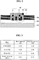
- silver (Ag) has a work function of about 4.26 eV
- nickel (Ni) has a work function of about 5.10 eV which is greater than silver (Ag).
- Schottky barrier of silver (Ag) is about 0.89
- Schottky barrier of nickel (Ni) is about 0.05 which is much less than silver (Ag).
- a contact resistance between the first doped region 120 and the first electrode part 140 including the first conductive particles P1 and the second conductive particles P2 having the work function greater than the first conductive particles P1 is less than a contact resistance between the first doped region 120 and the first electrode part including only the first conductive particles P1.
- nickel silicide (NiSi) formed at the interface between the second conductive particles P2 and the first doped region 120 has a work function of about 4.82 eV and Schottky barrier of about 0.33. Therefore, nickel silicide (NiSi) has the work function less than nickel (Ni) and the Schottky barrier greater than nickel (Ni). However, nickel silicide (NiSi) has a specific resistance less than nickel (Ni).
- the contact resistance between the first doped region 120 and the first electrode part 140 is further reduced by nickel silicide (NiSi) formed at the interface between the second conductive particles P2 and the first doped region 120.
- NiSi nickel silicide
- Schottky barrier of a related art first electrode part including only first conductive particles has a first height ⁇ b1.
- Schottky barrier of the first electrode part 140 according to the embodiment of the invention including the first conductive particles P1, the second conductive particles P2, and nickel silicide (NiSi) has a second height ⁇ b2 which is less than the first height ⁇ b1 by a predetermined height ⁇ b.
- the first electrode part 140 includes about 15 wt% to 25 wt% of the nickel particles P2 based on the total weight of the silver particles P1 and the nickel particles P2.
- a specific resistance of the nickel particles P2 is about five times greater than a specific resistance of the silver particles P1
- the electrical characteristics of the solar cell when only the nickel particles P2 are used as the conductive particles distributed in the thermosetting resin R of the first electrode part 140 are reduced because of a very large line resistance of the first electrode part 140.
- the line resistance of the first electrode part 140 increases as an amount of nickel particles P2 increases.
- an amount of nickel particles P2 based on the total weight of the silver particles P1 and the nickel particles P2 is set in consideration of the line resistance of the first electrode part 140 and the contact resistance between the first doped region 120 and the first electrode part 140.
- the amount of nickel particles P2 is about 15 wt% to 25 wt% based on the total weight of the silver particles P1 and the nickel particles P2.
- an additive such as a distribution stabilizer, has to be used because it is difficult to efficiently distribute the nickel particles P2 in the resin R.
- the additive increases the line resistance of the first electrode part 140.
- the size of the nickel particles P2 may refer to a diameter.
- the nickel particles P2 may be efficiently distributed in the resin R by using the nickel particles P2 having the size expressed in the unit of micro.
- the size of the nickel particles P2 is about 2 ⁇ m to 10 ⁇ m.
- the first electrode part 140 of the above-described configuration collects carriers (for example, holes) moving to the first doped region 120.
- the second electrode part 170 positioned on the back surface of the substrate 110 collects carriers (for example, electrons) moving to the substrate 110 and outputs the carriers to an external device.
- carriers for example, electrons
- the second electrode part 170 includes a plurality of finger electrodes 170a formed at a location corresponding to the finger electrodes 140a of the first electrode part 140 and a plurality of bus bar electrodes 170b formed at a location corresponding to the bus bar electrodes 140b of the first electrode part 140.
- the number of finger electrodes 170a of the second electrode part 170 is more than the number of finger electrodes 140a of the first electrode part 140.
- the second electrode part 170 may be formed using the same electrode paste as the first electrode part 140.
- the second electrode part 170 may be formed by printing, drying, and curing the electrode paste including the resin R and the first and second conductive particles P1 and P2 distributed in the resin R.
- the second doped region 150 electrically and/or physically connected to the second electrode part 170 is positioned at the entire back surface of the substrate 110 and forms a potential barrier by a difference between impurity doping concentrations of the substrate 110 and the second doped region 150.
- the second doped region 150 serves as a back surface field region which prevents or reduces holes from moving to the back surface of the substrate 110. As a result, a recombination and/or a disappearance of electrons and holes at and around the surface of the substrate 110 are reduced.
- the second doped region 150 may be locally positioned at the back surface of the substrate 110, on which the second electrode part 170 is positioned, and may have a selective structure having different impurity doping concentrations in the same manner as the selective emitter region.
- an impurity doping concentration of the second doped region 150, on which the second electrode part 170 is positioned may be higher or lower than an impurity doping concentration of the second doped region 150, on which the second electrode part 170 is not positioned.
- silicide is formed at an interface between the second conductive particles P2 and the second doped region 150 in the same or similar manner as the first electrode part 140.
- the first doped region 120 shown in FIG. 2 may be the second doped region 150
- the front dielectric layer 130 may be a back dielectric layer 160 positioned on the back surface of the second doped region 150, on which the second electrode part 170 is not positioned.
- the back dielectric layer 160 may be formed of at least one of silicon nitride (SiNx), silicon oxide (SiOx), aluminum oxide (AlOx), and titanium dioxide (TiO 2 ) in the same manner as the front dielectric layer 130.
- the back dielectric layer 160 may be omitted if necessary or desired, in the same manner as the front dielectric layer 130.
- the front dielectric layer 130 When the front dielectric layer 130 is positioned on the front surface of the substrate 110 and the back dielectric layer 160 is positioned on the back surface of the substrate 110, the front dielectric layer 130 and the back dielectric layer 160 reduce a reflection loss of light incident on the substrate 110. Hence, an amount of light incident on the substrate 110 further increases.
- the electron-hole pairs are separated into electrons and holes by the p-n junction between the substrate 110 and the first doped region 120. Then, the separated electrons move to the n-type substrate 110, and the separated holes move to the p-type first doped region 120.
- the electrons moving to the substrate 110 move to the second electrode part 170 through the second doped region 150, and the holes moving to the first doped region 120 move to the first electrode part 140.
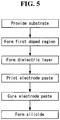
- FIG. 5 is a block diagram illustrating a method for manufacturing the solar cell shown in FIG. 1 .
- the first doped region 120 containing impurities of the second conductive type opposite the first conductive type is formed at the first surface of the substrate (for example, the n-type substrate 110) of the first conductive type.
- the first surface of the substrate 110 may be textured to form a textured surface corresponding to an uneven surface having a plurality of uneven portions or having uneven characteristics.
- the front dielectric layer 130 is formed on the first doped region 120.
- the front dielectric layer 130 may be formed using a chemical vapor deposition (CVD) method such as a plasma enhanced chemical vapor deposition (PECVD) method.
- CVD chemical vapor deposition
- PECVD plasma enhanced chemical vapor deposition
- the front dielectric layer 130 may have a single-layered structure or a multi-layered structure.
- the front dielectric layer 130 is partially etched to expose a portion of the first doped region 120, in which the first electrode part 140 is formed.
- the front dielectric layer 130 includes an opening exposing the portion of the first doped region 120.
- the opening may be formed in the same pattern (for example, a grid pattern) as the first electrode part 140.
- a laser may be used to form the opening in the front dielectric layer 130, but the embodiment of the invention is not limited thereto.
- a photolithography process may be used.
- an electrode paste for low temperature curing is printed and dried on the first doped region 120 exposed by the opening of the front dielectric layer 130.
- the embodiment of the invention is described as having the electrode paste printed and dried after forming the front dielectric layer 130.
- the electrode paste may be printed and dried in a state where the front dielectric layer 130 is not formed on the first doped region 120.
- the electrode paste for low temperature curing includes a thermosetting resin R, first conductive particles P1 distributed in the thermosetting resin R, and second conductive particles P2 which are distributed in the thermosetting resin R and having a work function greater than the first conductive particles P1, and forming silicide at an interface contacting the first doped region 120.
- the thermosetting resin R may include one of a monomer-based epoxy resin and an acrylic resin which are thermally processed and cured at a low temperature (for example, about 230 °C to 260 °C).
- the first conductive particles P1 may be silver (Ag) particles
- the second conductive particles P2 may be nickel (Ni) particles.
- a thermal process is performed on the electrode paste for low temperature curing at a low temperature of about 240 °C to cure the electrode paste.
- a thermal process which is performed at a temperature (for example, about 800 °C to 900 °C) higher than the electrode paste for low temperature curing according to the embodiment of the invention, has to be used to cure a related art electrode paste including a glass frit and first conductive particles (for example, Ag particles) distributed in the glass frit.
- a temperature for example, about 800 °C to 900 °C
- first conductive particles for example, Ag particles
- the electrode paste for low temperature curing does not include the glass frit including an etching component and includes the thermosetting resin R, which is cured at the low temperature (for example, about 230 °C to 260 °C), instead of the glass frit. Therefore, a heat damage applied to the first doped region 120 and the substrate 110 may be minimized. Hence, life time of a silicon bulk forming the substrate 110 increases, and an open-circuit voltage and a short circuit current density are improved. As a result, the efficiency of the solar cell may be improved.
- the substrate 110 is heated at the temperature of about 350 °C to 400 °C in an atmosphere of an inert gas to form silicide at the interface at which the second conductive particles P2 and the first doped region 120 contact each other.
- nickel silicide NiSi is formed at the interface contacting the first doped region 120.
- the method for manufacturing the bifacial solar cell according to the embodiment of the invention may include forming the first doped region at the first surface of the substrate and forming the second doped region at the second surface of the substrate, forming the front dielectric layer on the first surface of the substrate and forming the back dielectric layer on the second surface of the substrate, forming the opening in each of the front dielectric layer and the back dielectric layer, applying the electrode paste for forming the first electrode part to the first doped region exposed through the opening of the front dielectric layer and applying the electrode paste for forming the second electrode part to the second doped region exposed through the opening of the back dielectric layer, performing the thermal process on the electrode paste for the first electrode part and the electrode paste for the second electrode part at the low temperature to cure the electrode pastes, and forming silicide.
Landscapes
- Photovoltaic Devices (AREA)
- Engineering & Computer Science (AREA)
- Life Sciences & Earth Sciences (AREA)
- Sustainable Energy (AREA)
- Sustainable Development (AREA)
- Manufacturing & Machinery (AREA)
Claims (11)
- Solarzelle, umfassend:ein Substrat (110) eines ersten Leitfähigkeitstyps;einen ersten dotierten Bereich (120), der an einer ersten Oberfläche des Substrats (110) angeordnet ist und Störstellen eines von dem ersten Leitfähigkeitstyp verschiedenen zweiten Leitfähigkeitstyps enthält; undein erstes Elektrodenteil (140), das elektrisch mit dem ersten dotierten Bereich (120) verbunden ist,wobei das erste Elektrodenteil (140) ein wärmehärtendes Harz (R) und in dem wärmehärtenden Harz (R) verteilte erste und zweite leitfähige Partikel (P1, P2) umfasst und die zweiten leitfähigen Partikel (P2) eine größere Austrittsarbeit als die ersten leitfähigen Partikel (P1) haben und Silicid (NS) an einer mit dem ersten dotierten Bereich (120) in Kontakt stehenden Grenzfläche bilden,dadurch gekennzeichnet, dass
die ersten leitfähigen Partikel (P1) aus Silber- (Ag) Partikeln gebildet sind und die zweiten leitfähigen Partikel (P2) aus Nickel- (Ni) Partikeln gebildet sind,
das gebildete Silicid (NS) Nickelsilicid (NS) ist, und
die Nickel-Partikel (P2) bezogen auf das Gesamtgewicht der Silber-Partikel (P1) und der Nickel-Partikel (P2) etwa 15 Gew% bis 25 Gew% betragen. - Solarzelle nach Anspruch 1, wobei eine Größe eines Nickel-Partikels (P2) ungefähr 2 µm bis 10 µm beträgt.
- Solarzelle nach Anspruch 1, wobei das wärmehärtende Harz (R) ein Monomerbasiertes Epoxyharz oder ein Acrylharz umfasst.
- Solarzelle nach Anspruch 1, wobei der erste dotierte Bereich (120) als ein Emitterbereich ausgebildet ist und eine dielektrische Schicht (130) auf dem Emitterbereich (120) gebildet ist.
- Solarzelle nach Anspruch 4, wobei das erste Elektrodenteil (140) eine Mehrzahl von ersten Fingerelektroden (140a), die sich in einer ersten Richtung erstrecken, und eine Mehrzahl von ersten Sammelschienenelektroden (140b), die sich in einer die ersten Fingerelektroden kreuzenden zweiten Richtung erstrecken, umfasst.
- Solarzelle nach Anspruch 1, ferner umfassend:einen zweiten dotierten Bereich (150), der an einer zweiten Oberfläche gegenüber der ersten Oberfläche des Substrats (110) angeordnet ist und Störstellen des ersten Leitfähigkeitstyps mit einer höheren Konzentration als das Substrat enthält; undein zweites Elektrodenteil (170), das elektrisch mit dem zweiten dotierten Bereich (160) verbunden ist,wobei das zweite Elektrodenteil (170) die ersten leitfähigen Partikel (P1), die zweiten leitfähigen Partikel (P2), Silicid (NS) und das wärmehärtende Harz (R) umfasst.
- Solarzelle nach Anspruch 6, wobei der zweite dotierte Bereich (150) als ein Rückseitenfeldbereich ausgebildet ist und eine dielektrische Schicht (160) auf dem Rückseitenfeldbereich (150) ausgebildet ist.
- Solarzelle nach Anspruch 7, wobei das zweite Elektrodenteil (170) eine Mehrzahl von zweiten Fingerelektroden (170a), die sich in einer ersten Richtung erstrecken, und eine Mehrzahl von zweiten Sammelschienenelektroden (170b), die sich in einer die zweiten Fingerelektroden (170a) kreuzenden zweiten Richtung erstrecken, umfasst.
- Verfahren zur Herstellung einer Solarzelle, umfassend:Bilden eines ersten dotierten Bereichs (120), der Störstellen eines von einem ersten Leitfähigkeitstyp verschiedenen zweiten Leitfähigkeitstyps enthält, an einer ersten Oberfläche eines Substrats (110) des ersten Leitfähigkeitstyps;Bilden einer dielektrischen Schicht (130) auf dem ersten dotierten Bereich (120);Bilden einer Öffnung an der dielektrischen Schicht (130) zum Freiliegen eines Teils des ersten dotierten Bereichs (120);Aufdrucken von einer Elektrodenpaste einschließlich eines wärmehärtenden Harzes (R), in dem wärmehärtenden Harz (R) verteilter erster leitfähiger Partikel (P1) und in dem wärmehärtenden Harz (R) verteilter zweiter leitfähiger Partikel (P2) und mit einer größeren Austrittsarbeit als die ersten leitfähigen Partikel (P1);Durchführen eines thermischen Prozesses auf der Elektrodenpaste bei einer Temperatur zum Aushärten der Elektrodenpaste; undBilden von Silicid (NS) an einer Grenzfläche, an der die zweiten leitfähigen Partikel (P2) und der erste dotierte Bereich (120) miteinander in Kontakt stehen,dadurch gekennzeichnet, dass
die ersten leitfähigen Partikel (P1) aus Silber- (Ag) Partikel gebildet sind und die zweiten leitfähigen Partikel (P2) aus Nickel- (Ni) Partikel gebildet sind,
die Nickel-Partikel (P2) bezogen auf das Gesamtgewicht der Silber-Partikel (P1) und der Nickel-Partikel (P2) ungefähr 15 Gew% bis 25 Gew% betragen, und
wobei das Bilden von Silicid ein Bilden von Nickelsilicid an der Grenzfläche, an welcher die zweiten leitfähigen Partikel und der erste dotierte Bereich miteinander in Kontakt stehen, durch Verwendung der aus Nickel gebildeten zweiten leitfähigen Partikel umfasst. - Verfahren nach Anspruch 9, wobei der auf der Elektrodenpaste durchgeführte thermische Prozess zum Aushärten der Elektrodenpaste bei einer Temperatur von ungefähr 230 °C bis 260 °C durchgeführt wird.
- Verfahren nach Anspruch 10, wobei das Bilden von Nickelsilicid ein Aufheizen des Substrats auf eine Temperatur von ungefähr 350 °C bis 400 °C umfasst.
Applications Claiming Priority (1)
| Application Number | Priority Date | Filing Date | Title |
|---|---|---|---|
| KR1020130056314A KR101614186B1 (ko) | 2013-05-20 | 2013-05-20 | 태양전지 및 이의 제조 방법 |
Publications (3)
| Publication Number | Publication Date |
|---|---|
| EP2806465A2 EP2806465A2 (de) | 2014-11-26 |
| EP2806465A3 EP2806465A3 (de) | 2015-04-01 |
| EP2806465B1 true EP2806465B1 (de) | 2017-01-04 |
Family
ID=50390981
Family Applications (1)
| Application Number | Title | Priority Date | Filing Date |
|---|---|---|---|
| EP14001166.9A Active EP2806465B1 (de) | 2013-05-20 | 2014-03-28 | Solarzelle und Verfahren zu ihrer Herstellung |
Country Status (5)
| Country | Link |
|---|---|
| US (1) | US11004988B2 (de) |
| EP (1) | EP2806465B1 (de) |
| JP (1) | JP5952336B2 (de) |
| KR (1) | KR101614186B1 (de) |
| CN (1) | CN104183656B (de) |
Families Citing this family (4)
| Publication number | Priority date | Publication date | Assignee | Title |
|---|---|---|---|---|
| DE202015102238U1 (de) * | 2015-05-04 | 2015-06-01 | Solarworld Innovations Gmbh | Photovoltaik-Zelle und Photovoltaik-Modul |
| CN116647680A (zh) | 2016-10-28 | 2023-08-25 | 韩国电子通信研究院 | 视频编码/解码方法和设备以及存储比特流的记录介质 |
| KR101980946B1 (ko) * | 2016-11-11 | 2019-05-21 | 삼성에스디아이 주식회사 | 태양전지용 전면 전극 및 이를 포함하는 태양전지 |
| KR20210103850A (ko) * | 2020-02-14 | 2021-08-24 | 엘지전자 주식회사 | 태양 전지, 그리고 태양 전지 패널 및 이의 제조 방법 |
Family Cites Families (21)
| Publication number | Priority date | Publication date | Assignee | Title |
|---|---|---|---|---|
| JPS5896777A (ja) | 1981-12-03 | 1983-06-08 | Mitsubishi Electric Corp | 太陽電池 |
| JP3254044B2 (ja) | 1993-06-16 | 2002-02-04 | ナミックス株式会社 | 太陽電池用電極 |
| JP3557148B2 (ja) | 2000-02-21 | 2004-08-25 | 三洋電機株式会社 | 太陽電池モジュール |
| US8575474B2 (en) | 2006-03-20 | 2013-11-05 | Heracus Precious Metals North America Conshohocken LLC | Solar cell contacts containing aluminum and at least one of boron, titanium, nickel, tin, silver, gallium, zinc, indium and copper |
| JP2008135654A (ja) | 2006-11-29 | 2008-06-12 | Sanyo Electric Co Ltd | 太陽電池モジュール |
| TWI330998B (en) * | 2007-01-16 | 2010-09-21 | Chimei Innolux Corp | Top emitter organic electroluminescent display |
| JP4992449B2 (ja) * | 2007-02-06 | 2012-08-08 | 株式会社村田製作所 | 厚膜導体組成物および太陽電池セルの裏面Ag電極 |
| US20100037941A1 (en) | 2008-08-13 | 2010-02-18 | E. I. Du Pont De Nemours And Company | Compositions and processes for forming photovoltaic devices |
| CN101752452A (zh) * | 2008-12-01 | 2010-06-23 | 台湾茂矽电子股份有限公司 | 双面太阳能电池的制造方法 |
| US8710355B2 (en) | 2008-12-22 | 2014-04-29 | E I Du Pont De Nemours And Company | Compositions and processes for forming photovoltaic devices |
| JP2010182935A (ja) * | 2009-02-06 | 2010-08-19 | Sharp Corp | 薄膜太陽電池の製造方法 |
| JP5144857B2 (ja) | 2010-03-01 | 2013-02-13 | 株式会社ノリタケカンパニーリミテド | 太陽電池用導電性ペースト組成物 |
| TWI475702B (zh) | 2010-07-09 | 2015-03-01 | 阪本順 | A panel, a panel manufacturing method, a solar cell module, a printing apparatus, and a printing method |
| US20120037216A1 (en) | 2010-08-13 | 2012-02-16 | Samsung Electronics Co., Ltd. | Conductive paste and electronic device and solar cell including an electrode formed using the conductive paste |
| KR101665722B1 (ko) | 2010-09-27 | 2016-10-24 | 엘지전자 주식회사 | 태양 전지 및 이의 제조 방법 |
| US20120142140A1 (en) * | 2010-12-02 | 2012-06-07 | Applied Nanotech Holdings, Inc. | Nanoparticle inks for solar cells |
| KR20120079591A (ko) | 2011-01-05 | 2012-07-13 | 엘지전자 주식회사 | 태양전지 및 그 제조 방법 |
| KR20120091629A (ko) * | 2011-02-09 | 2012-08-20 | 엘지전자 주식회사 | 태양전지 |
| DE102011016335B4 (de) | 2011-04-07 | 2013-10-02 | Universität Konstanz | Nickelhaltige und ätzende druckbare Paste sowie Verfahren zur Bildung von elektrischen Kontakten beim Herstellen einer Solarzelle |
| US8901414B2 (en) * | 2011-09-14 | 2014-12-02 | International Business Machines Corporation | Photovoltaic cells with copper grid |
| CN104011882A (zh) * | 2012-01-12 | 2014-08-27 | 应用材料公司 | 制造太阳能电池装置的方法 |
-
2013
- 2013-05-20 KR KR1020130056314A patent/KR101614186B1/ko active Active
-
2014
- 2014-03-20 US US14/221,111 patent/US11004988B2/en active Active
- 2014-03-28 EP EP14001166.9A patent/EP2806465B1/de active Active
- 2014-05-19 JP JP2014103448A patent/JP5952336B2/ja active Active
- 2014-05-20 CN CN201410214046.3A patent/CN104183656B/zh active Active
Non-Patent Citations (1)
| Title |
|---|
| None * |
Also Published As
| Publication number | Publication date |
|---|---|
| JP2014229904A (ja) | 2014-12-08 |
| CN104183656A (zh) | 2014-12-03 |
| EP2806465A3 (de) | 2015-04-01 |
| US11004988B2 (en) | 2021-05-11 |
| KR101614186B1 (ko) | 2016-04-20 |
| CN104183656B (zh) | 2017-01-18 |
| EP2806465A2 (de) | 2014-11-26 |
| KR20140136562A (ko) | 2014-12-01 |
| US20140338738A1 (en) | 2014-11-20 |
| JP5952336B2 (ja) | 2016-07-13 |
Similar Documents
| Publication | Publication Date | Title |
|---|---|---|
| CN103797583B (zh) | 太阳能电池模块 | |
| US10998456B2 (en) | Solar cell, method for manufacturing same and solar cell module | |
| EP2889916B1 (de) | Solarzelle und Verfahren zur Herstellung davon | |
| US20110132426A1 (en) | Solar cell module | |
| EP2458649B1 (de) | Solarzelle | |
| US9337357B2 (en) | Bifacial solar cell module | |
| US10164129B2 (en) | Solar cell | |
| EP2711988B1 (de) | Solarzelle und Verfahren zu ihrer Herstellung | |
| EP2538447B1 (de) | Solarzelle und Verfahren zu ihrer Herstellung | |
| EP2806465B1 (de) | Solarzelle und Verfahren zu ihrer Herstellung | |
| US8420927B2 (en) | Solar cell, method of manufacturing the same, and solar cell module | |
| KR101092468B1 (ko) | 태양 전지 및 그 제조 방법 | |
| KR101694553B1 (ko) | 태양 전지 모듈 | |
| US8507788B2 (en) | Solar cell panel | |
| KR20150035059A (ko) | 태양전지 모듈 및 이의 제조 방법 | |
| US20110132425A1 (en) | Solar cell module | |
| EP2618386B1 (de) | Beidseitige Solarzelle | |
| JP6294694B2 (ja) | 太陽電池およびその製造方法、ならびに太陽電池モジュール | |
| KR20120043241A (ko) | 태양전지 모듈 | |
| CN116830278A (zh) | 电极总成 | |
| WO2014148065A1 (ja) | 太陽電池 | |
| KR20150083747A (ko) | 태양전지 모듈 |
Legal Events
| Date | Code | Title | Description |
|---|---|---|---|
| PUAI | Public reference made under article 153(3) epc to a published international application that has entered the european phase |
Free format text: ORIGINAL CODE: 0009012 |
|
| 17P | Request for examination filed |
Effective date: 20140328 |
|
| AK | Designated contracting states |
Kind code of ref document: A2 Designated state(s): AL AT BE BG CH CY CZ DE DK EE ES FI FR GB GR HR HU IE IS IT LI LT LU LV MC MK MT NL NO PL PT RO RS SE SI SK SM TR |
|
| AX | Request for extension of the european patent |
Extension state: BA ME |
|
| PUAL | Search report despatched |
Free format text: ORIGINAL CODE: 0009013 |
|
| AK | Designated contracting states |
Kind code of ref document: A3 Designated state(s): AL AT BE BG CH CY CZ DE DK EE ES FI FR GB GR HR HU IE IS IT LI LT LU LV MC MK MT NL NO PL PT RO RS SE SI SK SM TR |
|
| AX | Request for extension of the european patent |
Extension state: BA ME |
|
| RIC1 | Information provided on ipc code assigned before grant |
Ipc: H01L 31/068 20120101ALI20150223BHEP Ipc: H01L 31/0224 20060101AFI20150223BHEP Ipc: H01L 31/18 20060101ALI20150223BHEP |
|
| RBV | Designated contracting states (corrected) |
Designated state(s): AL AT BE BG CH CY CZ DE DK EE ES FI FR GB GR HR HU IE IS IT LI LT LU LV MC MK MT NL NO PL PT RO RS SE SI SK SM TR |
|
| 17Q | First examination report despatched |
Effective date: 20160218 |
|
| GRAP | Despatch of communication of intention to grant a patent |
Free format text: ORIGINAL CODE: EPIDOSNIGR1 |
|
| INTG | Intention to grant announced |
Effective date: 20160729 |
|
| GRAS | Grant fee paid |
Free format text: ORIGINAL CODE: EPIDOSNIGR3 |
|
| STAA | Information on the status of an ep patent application or granted ep patent |
Free format text: STATUS: GRANT OF PATENT IS INTENDED |
|
| GRAA | (expected) grant |
Free format text: ORIGINAL CODE: 0009210 |
|
| STAA | Information on the status of an ep patent application or granted ep patent |
Free format text: STATUS: THE PATENT HAS BEEN GRANTED |
|
| AK | Designated contracting states |
Kind code of ref document: B1 Designated state(s): AL AT BE BG CH CY CZ DE DK EE ES FI FR GB GR HR HU IE IS IT LI LT LU LV MC MK MT NL NO PL PT RO RS SE SI SK SM TR |
|
| REG | Reference to a national code |
Ref country code: GB Ref legal event code: FG4D |
|
| REG | Reference to a national code |
Ref country code: CH Ref legal event code: EP |
|
| REG | Reference to a national code |
Ref country code: AT Ref legal event code: REF Ref document number: 860008 Country of ref document: AT Kind code of ref document: T Effective date: 20170115 |
|
| REG | Reference to a national code |
Ref country code: NL Ref legal event code: FP |
|
| REG | Reference to a national code |
Ref country code: IE Ref legal event code: FG4D |
|
| REG | Reference to a national code |
Ref country code: DE Ref legal event code: R096 Ref document number: 602014005909 Country of ref document: DE |
|
| REG | Reference to a national code |
Ref country code: LT Ref legal event code: MG4D |
|
| REG | Reference to a national code |
Ref country code: AT Ref legal event code: MK05 Ref document number: 860008 Country of ref document: AT Kind code of ref document: T Effective date: 20170104 |
|
| PG25 | Lapsed in a contracting state [announced via postgrant information from national office to epo] |
Ref country code: IS Free format text: LAPSE BECAUSE OF FAILURE TO SUBMIT A TRANSLATION OF THE DESCRIPTION OR TO PAY THE FEE WITHIN THE PRESCRIBED TIME-LIMIT Effective date: 20170504 Ref country code: NO Free format text: LAPSE BECAUSE OF FAILURE TO SUBMIT A TRANSLATION OF THE DESCRIPTION OR TO PAY THE FEE WITHIN THE PRESCRIBED TIME-LIMIT Effective date: 20170404 Ref country code: HR Free format text: LAPSE BECAUSE OF FAILURE TO SUBMIT A TRANSLATION OF THE DESCRIPTION OR TO PAY THE FEE WITHIN THE PRESCRIBED TIME-LIMIT Effective date: 20170104 Ref country code: GR Free format text: LAPSE BECAUSE OF FAILURE TO SUBMIT A TRANSLATION OF THE DESCRIPTION OR TO PAY THE FEE WITHIN THE PRESCRIBED TIME-LIMIT Effective date: 20170405 Ref country code: LT Free format text: LAPSE BECAUSE OF FAILURE TO SUBMIT A TRANSLATION OF THE DESCRIPTION OR TO PAY THE FEE WITHIN THE PRESCRIBED TIME-LIMIT Effective date: 20170104 Ref country code: FI Free format text: LAPSE BECAUSE OF FAILURE TO SUBMIT A TRANSLATION OF THE DESCRIPTION OR TO PAY THE FEE WITHIN THE PRESCRIBED TIME-LIMIT Effective date: 20170104 |
|
| PG25 | Lapsed in a contracting state [announced via postgrant information from national office to epo] |
Ref country code: LV Free format text: LAPSE BECAUSE OF FAILURE TO SUBMIT A TRANSLATION OF THE DESCRIPTION OR TO PAY THE FEE WITHIN THE PRESCRIBED TIME-LIMIT Effective date: 20170104 Ref country code: ES Free format text: LAPSE BECAUSE OF FAILURE TO SUBMIT A TRANSLATION OF THE DESCRIPTION OR TO PAY THE FEE WITHIN THE PRESCRIBED TIME-LIMIT Effective date: 20170104 Ref country code: SE Free format text: LAPSE BECAUSE OF FAILURE TO SUBMIT A TRANSLATION OF THE DESCRIPTION OR TO PAY THE FEE WITHIN THE PRESCRIBED TIME-LIMIT Effective date: 20170104 Ref country code: BG Free format text: LAPSE BECAUSE OF FAILURE TO SUBMIT A TRANSLATION OF THE DESCRIPTION OR TO PAY THE FEE WITHIN THE PRESCRIBED TIME-LIMIT Effective date: 20170404 Ref country code: PT Free format text: LAPSE BECAUSE OF FAILURE TO SUBMIT A TRANSLATION OF THE DESCRIPTION OR TO PAY THE FEE WITHIN THE PRESCRIBED TIME-LIMIT Effective date: 20170504 Ref country code: RS Free format text: LAPSE BECAUSE OF FAILURE TO SUBMIT A TRANSLATION OF THE DESCRIPTION OR TO PAY THE FEE WITHIN THE PRESCRIBED TIME-LIMIT Effective date: 20170104 Ref country code: PL Free format text: LAPSE BECAUSE OF FAILURE TO SUBMIT A TRANSLATION OF THE DESCRIPTION OR TO PAY THE FEE WITHIN THE PRESCRIBED TIME-LIMIT Effective date: 20170104 Ref country code: AT Free format text: LAPSE BECAUSE OF FAILURE TO SUBMIT A TRANSLATION OF THE DESCRIPTION OR TO PAY THE FEE WITHIN THE PRESCRIBED TIME-LIMIT Effective date: 20170104 |
|
| REG | Reference to a national code |
Ref country code: DE Ref legal event code: R097 Ref document number: 602014005909 Country of ref document: DE |
|
| PG25 | Lapsed in a contracting state [announced via postgrant information from national office to epo] |
Ref country code: EE Free format text: LAPSE BECAUSE OF FAILURE TO SUBMIT A TRANSLATION OF THE DESCRIPTION OR TO PAY THE FEE WITHIN THE PRESCRIBED TIME-LIMIT Effective date: 20170104 Ref country code: RO Free format text: LAPSE BECAUSE OF FAILURE TO SUBMIT A TRANSLATION OF THE DESCRIPTION OR TO PAY THE FEE WITHIN THE PRESCRIBED TIME-LIMIT Effective date: 20170104 Ref country code: CZ Free format text: LAPSE BECAUSE OF FAILURE TO SUBMIT A TRANSLATION OF THE DESCRIPTION OR TO PAY THE FEE WITHIN THE PRESCRIBED TIME-LIMIT Effective date: 20170104 Ref country code: SK Free format text: LAPSE BECAUSE OF FAILURE TO SUBMIT A TRANSLATION OF THE DESCRIPTION OR TO PAY THE FEE WITHIN THE PRESCRIBED TIME-LIMIT Effective date: 20170104 |
|
| REG | Reference to a national code |
Ref country code: CH Ref legal event code: PL |
|
| PLBE | No opposition filed within time limit |
Free format text: ORIGINAL CODE: 0009261 |
|
| STAA | Information on the status of an ep patent application or granted ep patent |
Free format text: STATUS: NO OPPOSITION FILED WITHIN TIME LIMIT |
|
| PG25 | Lapsed in a contracting state [announced via postgrant information from national office to epo] |
Ref country code: DK Free format text: LAPSE BECAUSE OF FAILURE TO SUBMIT A TRANSLATION OF THE DESCRIPTION OR TO PAY THE FEE WITHIN THE PRESCRIBED TIME-LIMIT Effective date: 20170104 Ref country code: SM Free format text: LAPSE BECAUSE OF FAILURE TO SUBMIT A TRANSLATION OF THE DESCRIPTION OR TO PAY THE FEE WITHIN THE PRESCRIBED TIME-LIMIT Effective date: 20170104 Ref country code: MC Free format text: LAPSE BECAUSE OF FAILURE TO SUBMIT A TRANSLATION OF THE DESCRIPTION OR TO PAY THE FEE WITHIN THE PRESCRIBED TIME-LIMIT Effective date: 20170104 |
|
| REG | Reference to a national code |
Ref country code: IE Ref legal event code: MM4A |
|
| REG | Reference to a national code |
Ref country code: FR Ref legal event code: ST Effective date: 20171130 |
|
| PG25 | Lapsed in a contracting state [announced via postgrant information from national office to epo] |
Ref country code: LU Free format text: LAPSE BECAUSE OF NON-PAYMENT OF DUE FEES Effective date: 20170328 Ref country code: FR Free format text: LAPSE BECAUSE OF NON-PAYMENT OF DUE FEES Effective date: 20170331 |
|
| PG25 | Lapsed in a contracting state [announced via postgrant information from national office to epo] |
Ref country code: CH Free format text: LAPSE BECAUSE OF NON-PAYMENT OF DUE FEES Effective date: 20170331 Ref country code: IE Free format text: LAPSE BECAUSE OF NON-PAYMENT OF DUE FEES Effective date: 20170328 Ref country code: SI Free format text: LAPSE BECAUSE OF FAILURE TO SUBMIT A TRANSLATION OF THE DESCRIPTION OR TO PAY THE FEE WITHIN THE PRESCRIBED TIME-LIMIT Effective date: 20170104 Ref country code: LI Free format text: LAPSE BECAUSE OF NON-PAYMENT OF DUE FEES Effective date: 20170331 |
|
| REG | Reference to a national code |
Ref country code: BE Ref legal event code: MM Effective date: 20170331 |
|
| PGFP | Annual fee paid to national office [announced via postgrant information from national office to epo] |
Ref country code: NL Payment date: 20180207 Year of fee payment: 5 |
|
| PG25 | Lapsed in a contracting state [announced via postgrant information from national office to epo] |
Ref country code: BE Free format text: LAPSE BECAUSE OF NON-PAYMENT OF DUE FEES Effective date: 20170331 |
|
| PGFP | Annual fee paid to national office [announced via postgrant information from national office to epo] |
Ref country code: IT Payment date: 20180315 Year of fee payment: 5 |
|
| PG25 | Lapsed in a contracting state [announced via postgrant information from national office to epo] |
Ref country code: MT Free format text: LAPSE BECAUSE OF NON-PAYMENT OF DUE FEES Effective date: 20170328 |
|
| GBPC | Gb: european patent ceased through non-payment of renewal fee |
Effective date: 20180328 |
|
| PG25 | Lapsed in a contracting state [announced via postgrant information from national office to epo] |
Ref country code: GB Free format text: LAPSE BECAUSE OF NON-PAYMENT OF DUE FEES Effective date: 20180328 |
|
| PG25 | Lapsed in a contracting state [announced via postgrant information from national office to epo] |
Ref country code: HU Free format text: LAPSE BECAUSE OF FAILURE TO SUBMIT A TRANSLATION OF THE DESCRIPTION OR TO PAY THE FEE WITHIN THE PRESCRIBED TIME-LIMIT; INVALID AB INITIO Effective date: 20140328 |
|
| PG25 | Lapsed in a contracting state [announced via postgrant information from national office to epo] |
Ref country code: CY Free format text: LAPSE BECAUSE OF FAILURE TO SUBMIT A TRANSLATION OF THE DESCRIPTION OR TO PAY THE FEE WITHIN THE PRESCRIBED TIME-LIMIT Effective date: 20170104 |
|
| REG | Reference to a national code |
Ref country code: NL Ref legal event code: MM Effective date: 20190401 |
|
| PG25 | Lapsed in a contracting state [announced via postgrant information from national office to epo] |
Ref country code: MK Free format text: LAPSE BECAUSE OF FAILURE TO SUBMIT A TRANSLATION OF THE DESCRIPTION OR TO PAY THE FEE WITHIN THE PRESCRIBED TIME-LIMIT Effective date: 20170104 |
|
| PG25 | Lapsed in a contracting state [announced via postgrant information from national office to epo] |
Ref country code: NL Free format text: LAPSE BECAUSE OF NON-PAYMENT OF DUE FEES Effective date: 20190401 |
|
| PG25 | Lapsed in a contracting state [announced via postgrant information from national office to epo] |
Ref country code: IT Free format text: LAPSE BECAUSE OF NON-PAYMENT OF DUE FEES Effective date: 20190328 |
|
| PG25 | Lapsed in a contracting state [announced via postgrant information from national office to epo] |
Ref country code: TR Free format text: LAPSE BECAUSE OF FAILURE TO SUBMIT A TRANSLATION OF THE DESCRIPTION OR TO PAY THE FEE WITHIN THE PRESCRIBED TIME-LIMIT Effective date: 20170104 |
|
| PG25 | Lapsed in a contracting state [announced via postgrant information from national office to epo] |
Ref country code: AL Free format text: LAPSE BECAUSE OF FAILURE TO SUBMIT A TRANSLATION OF THE DESCRIPTION OR TO PAY THE FEE WITHIN THE PRESCRIBED TIME-LIMIT Effective date: 20170104 |
|
| REG | Reference to a national code |
Ref country code: DE Ref legal event code: R081 Ref document number: 602014005909 Country of ref document: DE Owner name: SHANGRAO JINKO SOLAR TECHNOLOGY DEVELOPMENT CO, CN Free format text: FORMER OWNER: LG ELECTRONICS INC., SEOUL, KR Ref country code: DE Ref legal event code: R082 Ref document number: 602014005909 Country of ref document: DE Representative=s name: DREISS PATENTANWAELTE PARTG MBB, DE Ref country code: DE Ref legal event code: R082 Ref document number: 602014005909 Country of ref document: DE Representative=s name: MANITZ FINSTERWALD PATENT- UND RECHTSANWALTSPA, DE Ref country code: DE Ref legal event code: R081 Ref document number: 602014005909 Country of ref document: DE Owner name: TRINA SOLAR CO., LTD., CHANGZHOU, CN Free format text: FORMER OWNER: LG ELECTRONICS INC., SEOUL, KR Ref country code: DE Ref legal event code: R081 Ref document number: 602014005909 Country of ref document: DE Owner name: SHANGRAO XINYUAN YUEDONG TECHNOLOGY DEVELOPMEN, CN Free format text: FORMER OWNER: LG ELECTRONICS INC., SEOUL, KR |
|
| REG | Reference to a national code |
Ref country code: DE Ref legal event code: R081 Ref document number: 602014005909 Country of ref document: DE Owner name: TRINA SOLAR CO., LTD., CHANGZHOU, CN Free format text: FORMER OWNER: SHANGRAO JINKO SOLAR TECHNOLOGY DEVELOPMENT CO., LTD, SHANGRAO, JIANGXI PROVINCE, CN Ref country code: DE Ref legal event code: R081 Ref document number: 602014005909 Country of ref document: DE Owner name: SHANGRAO XINYUAN YUEDONG TECHNOLOGY DEVELOPMEN, CN Free format text: FORMER OWNER: SHANGRAO JINKO SOLAR TECHNOLOGY DEVELOPMENT CO., LTD, SHANGRAO, JIANGXI PROVINCE, CN |
|
| REG | Reference to a national code |
Ref country code: DE Ref legal event code: R082 Ref document number: 602014005909 Country of ref document: DE Representative=s name: MANITZ FINSTERWALD PATENT- UND RECHTSANWALTSPA, DE Ref country code: DE Ref legal event code: R081 Ref document number: 602014005909 Country of ref document: DE Owner name: TRINA SOLAR CO., LTD., CHANGZHOU, CN Free format text: FORMER OWNER: SHANGRAO XINYUAN YUEDONG TECHNOLOGY DEVELOPMENT CO. LTD, SHANGRAO, JIANGXI PROVINCE, CN |
|
| REG | Reference to a national code |
Ref country code: DE Ref legal event code: R079 Ref document number: 602014005909 Country of ref document: DE Free format text: PREVIOUS MAIN CLASS: H01L0031022400 Ipc: H10F0077200000 |
|
| PGFP | Annual fee paid to national office [announced via postgrant information from national office to epo] |
Ref country code: DE Payment date: 20250319 Year of fee payment: 12 |