EP2806093B1 - Verfahren und Vorrichtung zum Zuführen von Eckverbindern zu einer Steckstation - Google Patents
Verfahren und Vorrichtung zum Zuführen von Eckverbindern zu einer Steckstation Download PDFInfo
- Publication number
- EP2806093B1 EP2806093B1 EP14001714.6A EP14001714A EP2806093B1 EP 2806093 B1 EP2806093 B1 EP 2806093B1 EP 14001714 A EP14001714 A EP 14001714A EP 2806093 B1 EP2806093 B1 EP 2806093B1
- Authority
- EP
- European Patent Office
- Prior art keywords
- angle
- guide surface
- corner connector
- limb
- corner
- Prior art date
- Legal status (The legal status is an assumption and is not a legal conclusion. Google has not performed a legal analysis and makes no representation as to the accuracy of the status listed.)
- Active
Links
Images


Classifications
-
- E—FIXED CONSTRUCTIONS
- E06—DOORS, WINDOWS, SHUTTERS, OR ROLLER BLINDS IN GENERAL; LADDERS
- E06B—FIXED OR MOVABLE CLOSURES FOR OPENINGS IN BUILDINGS, VEHICLES, FENCES OR LIKE ENCLOSURES IN GENERAL, e.g. DOORS, WINDOWS, BLINDS, GATES
- E06B3/00—Window sashes, door leaves, or like elements for closing wall or like openings; Layout of fixed or moving closures, e.g. windows in wall or like openings; Features of rigidly-mounted outer frames relating to the mounting of wing frames
- E06B3/96—Corner joints or edge joints for windows, doors, or the like frames or wings
- E06B3/964—Corner joints or edge joints for windows, doors, or the like frames or wings using separate connection pieces, e.g. T-connection pieces
- E06B3/968—Corner joints or edge joints for windows, doors, or the like frames or wings using separate connection pieces, e.g. T-connection pieces characterised by the way the connecting pieces are fixed in or on the frame members
- E06B3/9681—Corner joints or edge joints for windows, doors, or the like frames or wings using separate connection pieces, e.g. T-connection pieces characterised by the way the connecting pieces are fixed in or on the frame members by press fit or adhesion
- E06B3/9682—Mitre joints
Definitions
- the invention relates to a method for supplying two at right angles to each other arranged angle leg having corner connectors to a plug-in station, and for such mating mit mit miter cut frame legs and insertion into this frame legs, that from rectangular spacer frame for insulating glass panes can be produced, the corner connector after a Singling lined up to the plug-in station for mating with the frame legs are guided by a first angle leg parallel to a curved guide surface and thereby the other second angle leg initially in the same plane or obliquely or at right angles to this particular downward directed or suspended such that the second angle leg of the corner connector is pivoted and / or extended or erected, and that the respective corner connector after leaving the guide surface in the direction of parallel to the morning moved moving surface angle leg and is inserted with this angle leg in the frame legs.
- the invention also relates to the use of a corner joint, with two arranged at right angles to each other, forming an angle between the angle legs which fit in inner longitudinal cavities of frame legs of spacer frame for insulating glass and connect them in position of use, in a device and / or a method of initially mentioned type.
- a device for fixing the corner connector in frame and wing profile pieces of aluminum and plastic windows is known.
- a slide brings a profile piece successively in different positions, wherein in a first position two movable milling heads mill the profile piece on the guide rail and a device applies an adhesive to the end face of the profile chambers, in a second position two movable spray guns with their mouthpieces introduce an adhesive into the profile chambers and in a third position a feeder slide the corner connectors brings from a magazine to a multiple slide, which pushes the corner connectors in the profile chambers.
- WO 87/00884 A1 From the WO 87/00884 A1 is a method and an apparatus for fixing a hollow profile to another hollow profile by means of a connector known.
- connecting pieces are introduced into their position of use in the hollow sections and these are then joined by an external, in the connection point reaching into the hole is injected adhesive which flows into provided in the connector channels, where it hardens and so the connection between the two hollow sections and the connecting piece manufactures.
- the guide surface on which the angle legs are transported along may have any shape, but the known from practice arrangement is chosen so that this guide surface is curved and the corner joints are moved with an angle leg parallel to this guide surface, wherein the curvature ensures that the first downwardly directed second angle legs are erected so that the first angle leg can be easily inserted into a frame leg, without requiring additional space during the displacement of the second angle leg of the corner connector.
- corner connectors arranged in a row obstruct each other during this transport at least partially and thereby can be tilted, for example, because the protruding from the guide surface and initially directed downward angle second leg of this corner each other through the curved transport and may possibly collide with each other.
- the inventive method provides for solving the problem that the corner connectors are held during their transport to the plug-in station with its parallel to the guide surface arranged angle legs at a distance from this guide surface and moved parallel to this to the plug-in station and that during the feed both angle legs of the corner connector are guided and the perpendicular to the first inserted first angle leg oriented second angle leg is guided directly or indirectly by a flat surface which is arranged at right angles to the curved guide surface.
- the corner connector is guided and displaced parallel to the guide surface during its transport to the plug-in station, this danger can be reduced or avoided and a more precise guidance can be achieved.
- corner connectors For the simplest possible conveying movement of the corner connectors, it is advantageous if these corner connectors are moved after their separation and alignment during their transport to the plug-in station via an oblique or downward or curved path and / or vibration and / or by means of shocks in the transport direction.
- This makes it possible, in particular, to provide a guide surface, which extends approximately over a semicircle, with spacers according to the invention, in order to pivot the latter, and nevertheless to be able to transport the corner connectors securely along it.
- the corner connectors can be turned in their advance relative to a starting position in particular by such an angle - for example, by 180 degrees - that the second angle leg is erected, and to the curved guide surface can describe a partial circle or semicircle. If the second angle leg at the beginning of the feed movement along this guide surface directed downwards or downwards, so it can be pivoted by the feed along the mentioned semicircle to the desired angle, so that it stands up when inserted into a frame legs and thus the insertion into this frame leg is simplified.
- the corner connectors in their manufacture on the arranged during the transport process parallel to the inside to the guide surface first angle leg on the outside with at least one - rigid or rigidly limited - recess provided ing surface parallel to this extending in the direction of transport projection or spacer, in particular in web, rail or strip shape at least partially over or encompasses and / or touched.
- a particularly precise and good guidance of the corner connectors results when these are positively detected and guided on the recess (s) of the angle leg (s).
- an improvement of the leadership and in particular an avoidance of unwanted pivoting of the guided angle leg during the feed can be largely achieved when the recess exceeds the cross section of the projection or spacer, because thereby limits at least the conceivable deflection of the corresponding angle leg to a still harmless measure can be, but the guide is even better if the recess by a corresponding cross-sectional shape with the extending in the direction of transport projection or spacer at least partially coincides such that during the entire transport a touch and thus a positive guidance can take place.
- At least one moving second angle leg at a distance to this holding with recesses on the outside of the second angle limb may be provided cooperating spacer or guide bar, that is, the second angle legs may be similar to the first angle leg provided with one or more rigid or unyielding recesses on which engage guide means that replace a flat contact during the feed.
- the initially defined device for supplying the belonging to her corner connector to the plug-in station may be characterized in that the guide surface has at least one protruding her projection or spacer in web, rail or strip form whose overall size or height or protrusion relative to the guide surface is greater than a recess on the outside of a respective first angle leg of the corner connector, wherein the corner connector has a recess which fits over the edge of the projection or spacer and this at least over or encompasses and / or touched in the position of use and that at right angles to the curved guide surface, a flat surface extends as the inside of a side wall, which forms with the guide surface a rectangular in cross-section angular space and in use as a direct or indirect stop for the second angle leg of the corner connector is used.
- the device defined at the outset according to the invention can thus better perform this during its feed, in cooperation with its associated corner connectors, that the corner connector has at least on the angle leg a rigidly limited or unyielding depression, which faces the guide surface during the feed.
- This recess can then cooperate with the projection or spacer such that a better alignment of the corner connector is maintained during its advancement.
- it may be, if on the flat surface and thus on the inside of the side wall guide webs are arranged to cooperate with provided on the outside of the respective second angle limb recesses, in the case of only one such depression a guide bar is sufficient.
- the cross-sectional profile of the projection or spacer which protrudes on the guide surface, at least at its furthest out of the guide surface edge region of the cross-sectional shape of a recess or recess on the angle leg of the corner correspond and the advantageously and expediently unyielding depression and the edge region of the projection or Spacers can fit together form-fitting.
- the intransigence or the rigid or rigid formation of the recess is at least helpful or necessary.
- the inside of the unyielding recess on the angle leg of the corner connector may have a larger dimension than corresponds to the cross section of the strip-like projection or spacer, so that the projection or spacer fills the recess or recess only partially and in particular may be an additional guide, for example a second Guide bar for cooperation with a second recess and / or arranged at right angles to the curved wall side wall serve as a side guide.
- the position of the corner connectors remains stable during their feed to the plug-in station.
- the inside or the cross-section of the recess on the angle leg or legs can therefore according to the needs and the course of the transport path be adapted to the cross-section of the projection or spacer to guide the corner connector relative to the guide surface well and, if necessary, to keep at the same time at a distance.
- the position of the corner connectors can be maintained during their advancement to the plug-in station, when parallel to the particular curved guide surface, a second bar or retaining wall - by far - runs, which engages under the inside of the first frame leg of the corner connector during its feed, and / / or leads. It can also have one or more spacers on the inside of the first frame leg of the corner connector during the feed effective retaining wall which abut during the feed on the inside of the angle leg of the corner connector and keep adjacent areas of this angle leg accordingly and optionally with recesses on the outside of the Angle leg interact.
- a plane arranged at right angles to the preferably curved or possibly obliquely extending guide surface can form with the guide surface a rectangular cross-section angular space and serve as a direct or indirect stop for the second angle leg of the corner connector so that it can assume a defined position during its advancement.
- one or more guide webs may be disposed on this flat abutment surface for cooperation with rigid recesses provided on the outside of the second angled limb, which in use may be overlapped or grasped and / or touched by the depressions or their unyielding edges.
- the guidance of the corner connectors during their feed is the guidance of the corner connectors during their feed.
- Parallel to the planar, at right angles to the curved guide surface extending surface may be arranged for engaging over the inside of the second angle leg of the respective corner connector, which terminates at a distance from the particular curved guide surface, the distance at least the thickness of the during displacement on the Guide surface along moving first angle leg including the distance from the guide surface corresponds, so that so this first angle leg outside the retaining wall, possibly touching its edge, can be transported.
- the lateral flat surface and the retaining wall may terminate at the bottom of the particular curved guide surface before the end or outlet region with a distance of at least the thickness of an angle leg and / or a slider for moving an angle leg transverse to the guide surface and transversely to the previous transport direction corresponds, so that this point corresponds to the plug-in station, from which the corner connector can be moved transversely to the previous transport direction and inserted with the first angle leg in a frame legs.
- a stop for each of the guide surface angle leg and the distance of this stop from the end of the flat lateral surface may be equal to or greater than the thickness dimension of this corner connector may be transverse to the orientations of the angle legs or less than twice that value.
- the guide surface is arcuate, in particular circular arc, preferably curved over a semicircle, it may have a straight, in particular oblique inlet and / or a rectilinear outlet, so that the corner connectors are optimally aligned before their combined displacement and pivoting along the curved guide surface and also during their supply stay well aligned in the plug-in station or if necessary, the alignment can be corrected again.
- both angle legs on their side facing away from the angular space of the corner outside at least one over the entire width of the outside and / or inside reaching, continuous, projecting in its cross-section or engaging recess or recess for Have over or encompassing and / or touching a web or rail or strip-shaped guide and that the recesses are rigidly bounded or unyielding to the angle legs of the corner connector and preferably have matching dimensions and / or shapes.
- This guide does not even have to be touched or constantly touched to effect stabilization of the position of the corner connectors during their advance. At least Any possible pivoting during the feed is limited. However, a positive connection is particularly favorable between deepening and additional guidance.
- At least one second unyielding recess can be provided for over or encompassing and / or touching a web or rail or rail-shaped guide.
- the compliance with the desired position of the corner connector during its feed is the following:
- the recesses on the one or more angle legs of the corner connector may be rigidly limited or unyielding, optionally in their course transverse to the angle leg from its beginning to its end each have a constant cross-section and preferably matching dimensions and / or shapes. However, it is not excluded that the respective inlet is chamfered in such a recess or rounded or provided with an inclined surface.
- the cross-section of at least one of the depressions may be channel-shaped, groove-shaped, angular, trapezoidal, curved and / or part-circular.
- an angular cross-sectional shape leads to a line, for example, in cross-section rounded bar, rail or strip-shaped guidance to line touch, which can be particularly precise.
- the greatest depth of the depression or depressions on at least one of the angle legs of the corner connector may, for example, correspond to about one third to two thirds or half the thickness of this angle leg or an intermediate value thereof. If the depth corresponds, for example, to one third of the thickness of the angle leg, it projects so deeply into this angle leg that the remaining material thickness is only two thirds of the thickness of this angle leg is. However, since the angle legs are not subjected to bending, through which the indentations could give way or even tear, the indentation may even extend to the middle or beyond beyond the respective angle leg in order to achieve the best possible adaptation to the bar, rail or to achieve strip-shaped spacers or guides.
- the corner connector can be inserted either with the one or the other angle leg first at the plug-in station in a frame leg, that is, the separation is simplified.
- a method, a device and in particular an important corner connector for connecting miter-cut frame legs of a spacer frame for insulating glass resulting in a precise supply of the individual corner connector to a plug-in station in that one or more unyielding depressions are provided on at least one angled limb or expediently on both angled limbs for co-operation with spacers or protrusions engaging in or touching them.
- the apparent overhead of attaching such wells to the corner connectors is thus more than offset by a significantly lower susceptibility to interference during the feeding of the corner connector to its plug-in station.
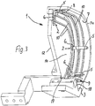
- a generally designated 1 device is used to supply at least temporarily belonging to this device 1 corner connectors 2 to a plug-in station 3, where these corner connectors 2 can be plugged together with honed frame legs 4.
- corner connectors 2 each have two mutually perpendicular angle legs 5 and 6, so that each angle leg 5 and 6 respectively in a frame leg 4 can be inserted, after which these two frame legs 4 are perpendicular to each other.
- the guide surface 7, which is located on the inside of a curved wall 7a, has in all embodiments, two parallel, opposing projections or spacers 10 in web, rail or strip shape, so that it is possible, the corner connectors 2 and the outer sides from the angle legs 5 with respect to the guide surface 7 to keep at a distance, so that they do not have to slide flat along it.
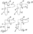
- first angle leg 5 On the outside of at least the first angle leg 5, expediently on the outer sides of both angle legs 5 and 6 are according to the FIGS. 7 to 11 one recess 11 or recess, according to FIGS. 16 and 17 even two such recesses 11 provided according to Fig. 2 and 3 cooperate with the mentioned spacers 10 such that the respective recess 11 fits at least over the edge of the projection or spacer 10 and this at least over or engages in the position of use and / or touched.
- the overall size or height or the projection of the spacer 10 relative to the guide surface 7 expediently larger than the dimension of the respective recess 11, so that the corner connector 2 and especially their first angle leg 5 during their Transports along the guide surface 7 to the plug-in station 3 can be kept at a distance from the guide surface 7 and moved parallel to this. A surface contact between the outside of the angle leg 5 and the guide surface 7 can thus be avoided.
- the cross-sectional profile of the projection or spacer 10 at least in its edge region of the cross-sectional shape of the recess 11 on the angle leg 5 - or as will be explained later also on the angle leg 6 - correspond to the corner connector 2 and the recess 11 and the recesses 11 according to Fig. 17 and at least the edge region of the projection or spacer 10 can fit together form fit.
- the inside of the recess 11 may have a larger dimension than corresponds to the cross section of the projection or spacer 10, so that the projection or spacer 10, the recess 11 only partially fills, but still allows mutual mutual contact good mutual guidance and support.
- an additional guide or even a second guide strip or a third and / or fourth guide strip and / or a side wall 12 arranged at right angles to the curved wall 7a and guide surface 7 serve as a lateral guide, on which the second angle leg 6 of the corner connector 2 can slide along during its feed.
- the first angle leg 5 are held on both sides during transport of the corner connector 2, without losing their desired orientation, ie without locking or jamming each other or at her Impede feed.
- each effective retaining wall 13 may also spacers 10 which abut during the feed on the inside of the angle leg 5 of the corner connector 2 or even engage in recesses, however, such a configuration is not provided in the embodiments.
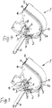
- FIGS. 1 to 3 can be seen also another important embodiment of the embodiments of the device 1, namely a perpendicular to the curved guide surface 7 extending flat surface 14 as the inside of the side wall 12 which forms a rectangular cross section with the guide surface 7 angled space and as a direct or indirect stop for each second angle leg 6 of the corner connector 2 is used.
- the second leg 6 of the corner connector 2 can either according to the Figures 1 and 2 lie directly against this flat surface 14 and thus the inside of the side wall 12 during its transport, or according to FIG.
- FIGS. 7 to 17 can also be arranged on this flat abutment surface 14 in the embodiment, two guide webs 10 for cooperation with provided on the outside of the respective second angle 6 recesses 11, which in use of the wells 11 or their edges in an analogous manner as in FIGS. 7 to 17 represented over or encompassed and / or touched.
- a retaining wall 16 is arranged to engage over the inside of the second angle leg 6 of the respective corner connector 2, with such a distance from the curved guide surface 7 ends that the first angle leg 5 they can overlap edge.
- the clear distance of the retaining wall 16 from the curved guide surface 7 thus corresponds to the thickness of the moving during the displacement of the guide surface 7 along the first angle leg 5 of the corner connector. 2
- FIGS. 1 to 3 and on the other hand the FIGS. 4 to 6 It is clear that the lateral flat surface 14 or the wall 12 having it and the retaining edge 16 in the lower region of the curved guide surface 7 ends before its end 9 or outlet region with a distance of at least the thickness of an angle leg 5 or 6 of a corner connector. 2 and a slide 17 for displacing a corner connector 2 transversely to the guide surface 7 and the previous feed direction corresponds, said slide 17 engages the outside of the angle leg 6 of each transported in the plug-in station 3 individual corner connector 2.
- a stop 18 for each coming from the guide surface 7 angle leg 5 or corner connector 2 and the distance of the stop 18 from the end 9 of the flat side surface 14 and its wall 12th is equal to or greater than the thickness dimension of the corner connector 2 transversely to its feed and transverse to the orientations of the angle legs or less than twice this value, so that the slider 17 can be moved transversely to the lateral surface 14 and the retaining wall 16 at the ends thereof to be in accordance with the Figures 5 and 6 a corner connector 2 from the series of along the guide surface 7 shifted and transported corner connector 2 can move out into a frame leg 4, while the following corner connectors 2 still remain in position relative to the guide surface 7 and the spacers 10 provided there.
- the substantially arcuate or circular arc-shaped curved guide surface 7 in the embodiments has a straight, in particular oblique inlet and also a straight, also slightly oblique outlet. As a result, the transport of the corner connector 2 is facilitated.
- FIGS. 1 to 6 are the important for the device 1 corner connector 2 already seen and explained with reference to the description of these figures. Even better, you can see this corner 2 in the FIGS. 7 to 17 , wherein especially on the outer sides of the angle leg 5 and / or 6 recognizable recesses 11 in several embodiments, but may also be different and at the same time the cooperating with them projections or spacers 10 may be shaped differently, in particular different dimensions or cross sections can have.
- the illustrated corner connectors 2 each have two angle legs 5 and 6, which are arranged at right angles to one another and form an angular space between them, which fit into inner longitudinal cavities of frame legs 4 of spacer frames for insulating glass panes ( Fig. 5 and 6 ) and these in the position of use approximately according to DE 10 2008 044 771 B3 connect.
- both angle legs 5 and 6 have on its outer corner facing away from the outside at least one over the entire width of the outside reaching, continuous, projecting into the respective cross-section or engaging, rigidly limited and unyielding recess 11th for over or encompassing or at least for touching a bar, rail or strip-shaped guide, which at the same time as a spacer 10 relative to the curved guide surface 7 and / or the side wall 12 (FIG. Fig. 3 ) protrudes.
- FIGS. 7 to 9 can be provided with approximately wedge-shaped or angular cross-section at both angle legs matching recesses 11, in which according to Fig. 7 the corresponding spacer 10 form fit or according to the FIGS. 8 and 9 can engage linearly touching.
- the wells 11 according to the FIGS. 10 and 11 match and are rounded in their depth circular arc.
- the cross sections of the intervening or contacting spacers 10 are in turn different either also rounded ( Fig. 10 ) or rectangular ( Fig. 11 profiled.
- the depressions 11 according to the FIGS. 12 to 15 have again matching profiles and thereby a rectangular or rectangular cross section in which differently profiled spacer 10 can engage, wherein the spacer 10 according to Fig. 15 with its cross section exceeds the cross section of the recess 11, but touched with its angled end, the edges of the recess 11.
- FIGS. 16 and 17 Corner connector 2 at both of which at right angles to each other arranged angle legs 5 and 6 are provided on the outer sides in each case two matching in cross section recesses 11, wherein in Fig. 16 is indicated that the two spacers 10 engage at an angle leg in the wells so that they each touch the boundaries facing away from each other, but not fill the wells 11, while Fig. 17 a solution with the wells 11 filling spacers 10 shows, but also spacers 10 according to the FIGS. 7 to 15 could be provided.
- FIGS. 16 and 17 So show examples of corner connectors 2, in which on the same side of the same angle leg 5 and / or 6, a second recess 11 for over or encompassing and / or touching a web or strip or rail-shaped guide or a spacer 10 is provided.
- the recesses 11 on the one or more angle legs 5 and / or 6 of the corner connector 2 from its beginning to its end, ie across the respective outer side of the respective angle leg and at right angles, respectively have a constant cross-section and matching dimensions and / or shapes.
- the cross section of the recesses 11 may be channel-shaped, grooved, angular, be trapezoidal, curved or part circular, as it is based on FIGS. 7 to 17 is recognizable and already explained.
- the depth of the recesses 11 at one or more angle legs 5 and / or 6 of the corner connector 2 corresponds in the embodiment about one third of the thickness of this angle leg between its outside and inside, but could also up to two-thirds or about half the thickness or a Intermediate value of this correspond.
- the two angle legs 5 and 6 of the respective corner connector 2 have a matching cross-sectional shape and length and are identical with respect to the recesses 11, so that the corner connectors can be easily inserted into the device 1, because the angle legs 5 and 6 against each other swapped or corner connectors can be arranged accordingly.
- a plug-in station 3 With the help of the device 1, the associated, two at right angles to each other arranged angle leg 5 and 6 having corner connector 2 a plug-in station 3 are supplied, where they can be plugged together with mitred frame legs 4 and inserted into this, that from a rectangular spacer frame for Insulated glass panes approximately according to DE 10 2008 044 771 B3 can be produced.
- the corner connectors 2 are thereby strung out after a separation to the plug-in station 3 transported that a first angle leg 5 of this corner joint 2 parallel to a curved guide surface in the embodiment 7 and the other second angle leg 6 first in the same plane or obliquely or according to the embodiment directed at right angles in particular downwards or suspended so that the second angle leg 6 of the corner connector 2 is pivoted or extended or erected during this transport and the respective corner connector 2 is moved after leaving the guide surface 7 in the direction of the angle leg 5 and inserted into the frame leg 4.
- the corner connectors 2 are held with their parallel to the guide surface 7 arranged angle legs 5 and the outer sides at a distance from this guide surface 7 and moved parallel to this.
- the corner connectors 2 are further moved after their separation during their transport to the plug-in station 3 via an inclined or downward or curved path and / or by vibration and / or by means of shocks in the transport direction, without causing a surface friction between the outside of the angle leg and the guide surface 7 inhibits this feed and / or the corner connectors 2 are pivoted during the feed relative to their desired orientation.
- the corner connectors 2 can be turned during their advance relative to a starting position by such an angle, for example by 180 °, that the second, originally downward angle leg 6 is erected and thereby that insertion into the frame leg 4 is facilitated.
- the guide surface 7 describes this seen from the side or in longitudinal section a pitch circle or preferably a semicircle.
- the outer side of one or more frame legs 4 of the corner connector 2 provided recess 11 in cooperation with a guide surface 7 following spacer 10 helps to ensure that the feed correspondingly precise can be done.
- the corner connectors 2 can be positively detected at the recess or recesses 11 and be guided quite accurately.
- both angle legs 5 and 6 of the corner connector 2 are guided while the second angle leg 6 is guided directly or indirectly via spacers 10 on the flat surface 14 which is perpendicular to the curved guide surface 7, whereby the corner connectors 2 can remain very precisely aligned during their feed.
Landscapes
- Engineering & Computer Science (AREA)
- Civil Engineering (AREA)
- Structural Engineering (AREA)
- Connector Housings Or Holding Contact Members (AREA)
- Details Of Connecting Devices For Male And Female Coupling (AREA)
Priority Applications (1)
| Application Number | Priority Date | Filing Date | Title |
|---|---|---|---|
| PL14001714T PL2806093T3 (pl) | 2013-05-23 | 2014-05-15 | Sposób i urządzenie do doprowadzania łączników kątowych na stanowisko łączenia |
Applications Claiming Priority (1)
| Application Number | Priority Date | Filing Date | Title |
|---|---|---|---|
| DE102013008768.6A DE102013008768A1 (de) | 2013-05-23 | 2013-05-23 | Verfahren und Vorrichtung zum Zuführen von Eckverbindern zu einer Steckstation |
Publications (2)
| Publication Number | Publication Date |
|---|---|
| EP2806093A1 EP2806093A1 (de) | 2014-11-26 |
| EP2806093B1 true EP2806093B1 (de) | 2017-08-23 |
Family
ID=50732741
Family Applications (1)
| Application Number | Title | Priority Date | Filing Date |
|---|---|---|---|
| EP14001714.6A Active EP2806093B1 (de) | 2013-05-23 | 2014-05-15 | Verfahren und Vorrichtung zum Zuführen von Eckverbindern zu einer Steckstation |
Country Status (4)
| Country | Link |
|---|---|
| EP (1) | EP2806093B1 (pl) |
| DE (1) | DE102013008768A1 (pl) |
| ES (1) | ES2647787T3 (pl) |
| PL (1) | PL2806093T3 (pl) |
Citations (3)
| Publication number | Priority date | Publication date | Assignee | Title |
|---|---|---|---|---|
| DE1575215A1 (de) * | 1967-01-25 | 1970-02-12 | Hermann Nickel | Verbindung von LM-Hohlprofilen,insbesondere Eckverbindungen fuer Fenster-,Tuerrahmen usw |
| DE3506443C1 (de) * | 1985-02-23 | 1986-06-26 | Wieland-Werke Ag, 7900 Ulm | Eckverbindung von auf Gehrung geschnittenen Rahmenprofilen für Fenster, Türen o.dgl. |
| DE19539862A1 (de) * | 1995-10-26 | 1997-04-30 | Ekonal Bausysteme Gmbh & Co Kg | Eckverbindung mit Einsatzstücken in Hohlkammern von Profilstäben zur Bildung von Rahmenteilen |
Family Cites Families (7)
| Publication number | Priority date | Publication date | Assignee | Title |
|---|---|---|---|---|
| NL8001828A (nl) * | 1980-03-27 | 1981-10-16 | Sten Sernevi | Werkwijze en inrichting voor het tot een raam samenvoegen van profielstaven en hoekstukken. |
| AT371557B (de) * | 1982-05-03 | 1983-07-11 | Schoelderle Kurt | Vorrichtung zur befestigung der eckverbinder in rahmen- und fluegelprofilstuecken von aluminiumundkunststoffenstern |
| SE457368B (sv) * | 1985-08-08 | 1988-12-19 | Nystroems Beslag Ab | Saett att vid skarvning av haalprofiler med hjaelp av skarvstycken foerse skarvstycket med bindemedel och anordning foer genomfoerande av detta saett |
| DE3822117A1 (de) * | 1988-06-30 | 1990-01-04 | Arup Alu Rohr Und Profil Gmbh | Eckverbinder fuer abstandshalterprofile von mehrscheiben-isolierglas |
| GB9217066D0 (en) * | 1992-08-12 | 1992-09-23 | Ukae Limited | Connector |
| DE19914031A1 (de) * | 1999-03-27 | 2000-09-28 | Winkhaus Fa August | Automatische Beschlagteilmontage für Rahmen |
| DE102008044771B3 (de) | 2008-08-28 | 2009-11-26 | R & R Sondermaschinen Gmbh | Verfahren und Vorrichtung zum Herstellen eines rechteckigen Abstandhalterrahmens für Isolierglasscheiben |
-
2013
- 2013-05-23 DE DE102013008768.6A patent/DE102013008768A1/de not_active Withdrawn
-
2014
- 2014-05-15 ES ES14001714.6T patent/ES2647787T3/es active Active
- 2014-05-15 PL PL14001714T patent/PL2806093T3/pl unknown
- 2014-05-15 EP EP14001714.6A patent/EP2806093B1/de active Active
Patent Citations (3)
| Publication number | Priority date | Publication date | Assignee | Title |
|---|---|---|---|---|
| DE1575215A1 (de) * | 1967-01-25 | 1970-02-12 | Hermann Nickel | Verbindung von LM-Hohlprofilen,insbesondere Eckverbindungen fuer Fenster-,Tuerrahmen usw |
| DE3506443C1 (de) * | 1985-02-23 | 1986-06-26 | Wieland-Werke Ag, 7900 Ulm | Eckverbindung von auf Gehrung geschnittenen Rahmenprofilen für Fenster, Türen o.dgl. |
| DE19539862A1 (de) * | 1995-10-26 | 1997-04-30 | Ekonal Bausysteme Gmbh & Co Kg | Eckverbindung mit Einsatzstücken in Hohlkammern von Profilstäben zur Bildung von Rahmenteilen |
Also Published As
| Publication number | Publication date |
|---|---|
| DE102013008768A1 (de) | 2014-11-27 |
| PL2806093T3 (pl) | 2018-01-31 |
| ES2647787T3 (es) | 2017-12-26 |
| EP2806093A1 (de) | 2014-11-26 |
Similar Documents
| Publication | Publication Date | Title |
|---|---|---|
| EP1407357B1 (de) | Befestigungsklammer zur verbindung von holzbauteilen | |
| EP3031547B1 (de) | Verfahren und vorrichtung zum herstellen einer eckverbindung | |
| CH659962A5 (de) | Maschine zum herstellen eines abstandhaltenden innenrahmens fuer eine isolierglasscheibe. | |
| EP2868856A2 (de) | Eckverbinder zum Verbinden auf Gehrung geschnittener Hohlprofile eines Fenster- oder Türrahmens | |
| WO2017063737A1 (de) | Pfosten-träger-verbindung und verfahren zu deren herstellung | |
| EP2876242A1 (de) | Verbindungsanordnung zum Befestigen eines Pfostens an einem Rahmenträger eines Fensters, einer Türe oder dgl. aus Kunststoff | |
| EP0320869A2 (de) | Hilfsvorrichtung zum Zinkenfräsen | |
| EP2307650A1 (de) | Linearverbinder für abstandhalter in isolierglasscheiben, verfahren zu seiner herstellung und zum verbinden zweier enden eines hohlprofilstabes für einen abstandhalter mit einem solchen linearverbinder | |
| DE2162381A1 (de) | Eckverbinder fuer doppel-hohlprofilstreben | |
| DE3020970C2 (de) | Bohrlehre | |
| EP2806093B1 (de) | Verfahren und Vorrichtung zum Zuführen von Eckverbindern zu einer Steckstation | |
| DE2325148C3 (de) | Vorrichtung zum Zusammenbau von Profilen für Metallstrukturen | |
| DE2902459C2 (de) | "Vorrichtung zum Befestigen des winkelförmigen Gehäuses einer Eckumlenkung in Nuten eines Flügelrahmens" | |
| DE2609388B2 (de) | Stabilisierungs- und Ausrichtelement für Gehrungsstöße zwischen zwei Bauprofilen | |
| DE102015101575A1 (de) | Langgestrecktes Mehrkantprofil sowie daraus hergestelles Winkelelement und Herstellverfahren | |
| DE2810630C3 (de) | Verbundprofil | |
| EP0438046B1 (de) | Eckverbinder für Zargen u.dergl. | |
| CH687716A5 (de) | Beschlag. | |
| AT409289B (de) | Steckverbindung zum verbinden von hohlprofilen | |
| DE2149422C3 (de) | Eckverbindung von Rahmenteilen, die zu Rahmen von Fenstern, Türen od.dgl. zusammengesetzt sind | |
| DE3123296C2 (de) | Stromentnahmeschiene | |
| DE102007009667A1 (de) | Profilkonstruktion | |
| DE2202599C3 (de) | Eckumlenkung für Treibstangen an Dreh-Kipp-Fenstern oder -Türen | |
| DE19700698C1 (de) | Zusammensetzbare Zarge, insbesondere Türzarge | |
| DE2256761C3 (de) | Vorrichtung (Schleuse) zum Einfuhren von Tragelementen von Vorhängen in eine Führungsschiene |
Legal Events
| Date | Code | Title | Description |
|---|---|---|---|
| PUAI | Public reference made under article 153(3) epc to a published international application that has entered the european phase |
Free format text: ORIGINAL CODE: 0009012 |
|
| 17P | Request for examination filed |
Effective date: 20140515 |
|
| AK | Designated contracting states |
Kind code of ref document: A1 Designated state(s): AL AT BE BG CH CY CZ DE DK EE ES FI FR GB GR HR HU IE IS IT LI LT LU LV MC MK MT NL NO PL PT RO RS SE SI SK SM TR |
|
| AX | Request for extension of the european patent |
Extension state: BA ME |
|
| R17P | Request for examination filed (corrected) |
Effective date: 20150428 |
|
| RBV | Designated contracting states (corrected) |
Designated state(s): AL AT BE BG CH CY CZ DE DK EE ES FI FR GB GR HR HU IE IS IT LI LT LU LV MC MK MT NL NO PL PT RO RS SE SI SK SM TR |
|
| 17Q | First examination report despatched |
Effective date: 20161028 |
|
| GRAP | Despatch of communication of intention to grant a patent |
Free format text: ORIGINAL CODE: EPIDOSNIGR1 |
|
| INTG | Intention to grant announced |
Effective date: 20170403 |
|
| GRAS | Grant fee paid |
Free format text: ORIGINAL CODE: EPIDOSNIGR3 |
|
| GRAJ | Information related to disapproval of communication of intention to grant by the applicant or resumption of examination proceedings by the epo deleted |
Free format text: ORIGINAL CODE: EPIDOSDIGR1 |
|
| GRAL | Information related to payment of fee for publishing/printing deleted |
Free format text: ORIGINAL CODE: EPIDOSDIGR3 |
|
| GRAR | Information related to intention to grant a patent recorded |
Free format text: ORIGINAL CODE: EPIDOSNIGR71 |
|
| GRAA | (expected) grant |
Free format text: ORIGINAL CODE: 0009210 |
|
| INTC | Intention to grant announced (deleted) | ||
| AK | Designated contracting states |
Kind code of ref document: B1 Designated state(s): AL AT BE BG CH CY CZ DE DK EE ES FI FR GB GR HR HU IE IS IT LI LT LU LV MC MK MT NL NO PL PT RO RS SE SI SK SM TR |
|
| INTG | Intention to grant announced |
Effective date: 20170718 |
|
| REG | Reference to a national code |
Ref country code: GB Ref legal event code: FG4D Free format text: NOT ENGLISH |
|
| REG | Reference to a national code |
Ref country code: CH Ref legal event code: EP |
|
| REG | Reference to a national code |
Ref country code: AT Ref legal event code: REF Ref document number: 921541 Country of ref document: AT Kind code of ref document: T Effective date: 20170915 |
|
| REG | Reference to a national code |
Ref country code: IE Ref legal event code: FG4D Free format text: LANGUAGE OF EP DOCUMENT: GERMAN |
|
| REG | Reference to a national code |
Ref country code: DE Ref legal event code: R096 Ref document number: 502014005119 Country of ref document: DE |
|
| REG | Reference to a national code |
Ref country code: ES Ref legal event code: FG2A Ref document number: 2647787 Country of ref document: ES Kind code of ref document: T3 Effective date: 20171226 |
|
| REG | Reference to a national code |
Ref country code: NL Ref legal event code: MP Effective date: 20170823 |
|
| REG | Reference to a national code |
Ref country code: LT Ref legal event code: MG4D |
|
| PG25 | Lapsed in a contracting state [announced via postgrant information from national office to epo] |
Ref country code: SE Free format text: LAPSE BECAUSE OF FAILURE TO SUBMIT A TRANSLATION OF THE DESCRIPTION OR TO PAY THE FEE WITHIN THE PRESCRIBED TIME-LIMIT Effective date: 20170823 Ref country code: HR Free format text: LAPSE BECAUSE OF FAILURE TO SUBMIT A TRANSLATION OF THE DESCRIPTION OR TO PAY THE FEE WITHIN THE PRESCRIBED TIME-LIMIT Effective date: 20170823 Ref country code: NL Free format text: LAPSE BECAUSE OF FAILURE TO SUBMIT A TRANSLATION OF THE DESCRIPTION OR TO PAY THE FEE WITHIN THE PRESCRIBED TIME-LIMIT Effective date: 20170823 Ref country code: FI Free format text: LAPSE BECAUSE OF FAILURE TO SUBMIT A TRANSLATION OF THE DESCRIPTION OR TO PAY THE FEE WITHIN THE PRESCRIBED TIME-LIMIT Effective date: 20170823 Ref country code: NO Free format text: LAPSE BECAUSE OF FAILURE TO SUBMIT A TRANSLATION OF THE DESCRIPTION OR TO PAY THE FEE WITHIN THE PRESCRIBED TIME-LIMIT Effective date: 20171123 Ref country code: LT Free format text: LAPSE BECAUSE OF FAILURE TO SUBMIT A TRANSLATION OF THE DESCRIPTION OR TO PAY THE FEE WITHIN THE PRESCRIBED TIME-LIMIT Effective date: 20170823 |
|
| PG25 | Lapsed in a contracting state [announced via postgrant information from national office to epo] |
Ref country code: RS Free format text: LAPSE BECAUSE OF FAILURE TO SUBMIT A TRANSLATION OF THE DESCRIPTION OR TO PAY THE FEE WITHIN THE PRESCRIBED TIME-LIMIT Effective date: 20170823 Ref country code: IS Free format text: LAPSE BECAUSE OF FAILURE TO SUBMIT A TRANSLATION OF THE DESCRIPTION OR TO PAY THE FEE WITHIN THE PRESCRIBED TIME-LIMIT Effective date: 20171223 Ref country code: LV Free format text: LAPSE BECAUSE OF FAILURE TO SUBMIT A TRANSLATION OF THE DESCRIPTION OR TO PAY THE FEE WITHIN THE PRESCRIBED TIME-LIMIT Effective date: 20170823 Ref country code: BG Free format text: LAPSE BECAUSE OF FAILURE TO SUBMIT A TRANSLATION OF THE DESCRIPTION OR TO PAY THE FEE WITHIN THE PRESCRIBED TIME-LIMIT Effective date: 20171123 Ref country code: GR Free format text: LAPSE BECAUSE OF FAILURE TO SUBMIT A TRANSLATION OF THE DESCRIPTION OR TO PAY THE FEE WITHIN THE PRESCRIBED TIME-LIMIT Effective date: 20171124 |
|
| PG25 | Lapsed in a contracting state [announced via postgrant information from national office to epo] |
Ref country code: DK Free format text: LAPSE BECAUSE OF FAILURE TO SUBMIT A TRANSLATION OF THE DESCRIPTION OR TO PAY THE FEE WITHIN THE PRESCRIBED TIME-LIMIT Effective date: 20170823 Ref country code: CZ Free format text: LAPSE BECAUSE OF FAILURE TO SUBMIT A TRANSLATION OF THE DESCRIPTION OR TO PAY THE FEE WITHIN THE PRESCRIBED TIME-LIMIT Effective date: 20170823 Ref country code: RO Free format text: LAPSE BECAUSE OF FAILURE TO SUBMIT A TRANSLATION OF THE DESCRIPTION OR TO PAY THE FEE WITHIN THE PRESCRIBED TIME-LIMIT Effective date: 20170823 |
|
| REG | Reference to a national code |
Ref country code: FR Ref legal event code: PLFP Year of fee payment: 5 |
|
| REG | Reference to a national code |
Ref country code: DE Ref legal event code: R097 Ref document number: 502014005119 Country of ref document: DE |
|
| PG25 | Lapsed in a contracting state [announced via postgrant information from national office to epo] |
Ref country code: SM Free format text: LAPSE BECAUSE OF FAILURE TO SUBMIT A TRANSLATION OF THE DESCRIPTION OR TO PAY THE FEE WITHIN THE PRESCRIBED TIME-LIMIT Effective date: 20170823 Ref country code: SK Free format text: LAPSE BECAUSE OF FAILURE TO SUBMIT A TRANSLATION OF THE DESCRIPTION OR TO PAY THE FEE WITHIN THE PRESCRIBED TIME-LIMIT Effective date: 20170823 Ref country code: EE Free format text: LAPSE BECAUSE OF FAILURE TO SUBMIT A TRANSLATION OF THE DESCRIPTION OR TO PAY THE FEE WITHIN THE PRESCRIBED TIME-LIMIT Effective date: 20170823 |
|
| PLBE | No opposition filed within time limit |
Free format text: ORIGINAL CODE: 0009261 |
|
| STAA | Information on the status of an ep patent application or granted ep patent |
Free format text: STATUS: NO OPPOSITION FILED WITHIN TIME LIMIT |
|
| 26N | No opposition filed |
Effective date: 20180524 |
|
| PG25 | Lapsed in a contracting state [announced via postgrant information from national office to epo] |
Ref country code: SI Free format text: LAPSE BECAUSE OF FAILURE TO SUBMIT A TRANSLATION OF THE DESCRIPTION OR TO PAY THE FEE WITHIN THE PRESCRIBED TIME-LIMIT Effective date: 20170823 |
|
| PG25 | Lapsed in a contracting state [announced via postgrant information from national office to epo] |
Ref country code: MT Free format text: LAPSE BECAUSE OF FAILURE TO SUBMIT A TRANSLATION OF THE DESCRIPTION OR TO PAY THE FEE WITHIN THE PRESCRIBED TIME-LIMIT Effective date: 20170823 |
|
| REG | Reference to a national code |
Ref country code: CH Ref legal event code: PL |
|
| PG25 | Lapsed in a contracting state [announced via postgrant information from national office to epo] |
Ref country code: MC Free format text: LAPSE BECAUSE OF FAILURE TO SUBMIT A TRANSLATION OF THE DESCRIPTION OR TO PAY THE FEE WITHIN THE PRESCRIBED TIME-LIMIT Effective date: 20170823 |
|
| REG | Reference to a national code |
Ref country code: IE Ref legal event code: MM4A |
|
| PG25 | Lapsed in a contracting state [announced via postgrant information from national office to epo] |
Ref country code: CH Free format text: LAPSE BECAUSE OF NON-PAYMENT OF DUE FEES Effective date: 20180531 Ref country code: LI Free format text: LAPSE BECAUSE OF NON-PAYMENT OF DUE FEES Effective date: 20180531 |
|
| PG25 | Lapsed in a contracting state [announced via postgrant information from national office to epo] |
Ref country code: LU Free format text: LAPSE BECAUSE OF NON-PAYMENT OF DUE FEES Effective date: 20180515 |
|
| PG25 | Lapsed in a contracting state [announced via postgrant information from national office to epo] |
Ref country code: IE Free format text: LAPSE BECAUSE OF NON-PAYMENT OF DUE FEES Effective date: 20180515 |
|
| PG25 | Lapsed in a contracting state [announced via postgrant information from national office to epo] |
Ref country code: TR Free format text: LAPSE BECAUSE OF FAILURE TO SUBMIT A TRANSLATION OF THE DESCRIPTION OR TO PAY THE FEE WITHIN THE PRESCRIBED TIME-LIMIT Effective date: 20170823 |
|
| PG25 | Lapsed in a contracting state [announced via postgrant information from national office to epo] |
Ref country code: PT Free format text: LAPSE BECAUSE OF FAILURE TO SUBMIT A TRANSLATION OF THE DESCRIPTION OR TO PAY THE FEE WITHIN THE PRESCRIBED TIME-LIMIT Effective date: 20170823 Ref country code: HU Free format text: LAPSE BECAUSE OF FAILURE TO SUBMIT A TRANSLATION OF THE DESCRIPTION OR TO PAY THE FEE WITHIN THE PRESCRIBED TIME-LIMIT; INVALID AB INITIO Effective date: 20140515 |
|
| PG25 | Lapsed in a contracting state [announced via postgrant information from national office to epo] |
Ref country code: MK Free format text: LAPSE BECAUSE OF NON-PAYMENT OF DUE FEES Effective date: 20170823 Ref country code: CY Free format text: LAPSE BECAUSE OF FAILURE TO SUBMIT A TRANSLATION OF THE DESCRIPTION OR TO PAY THE FEE WITHIN THE PRESCRIBED TIME-LIMIT Effective date: 20170823 |
|
| PG25 | Lapsed in a contracting state [announced via postgrant information from national office to epo] |
Ref country code: AL Free format text: LAPSE BECAUSE OF FAILURE TO SUBMIT A TRANSLATION OF THE DESCRIPTION OR TO PAY THE FEE WITHIN THE PRESCRIBED TIME-LIMIT Effective date: 20170823 |
|
| PGFP | Annual fee paid to national office [announced via postgrant information from national office to epo] |
Ref country code: ES Payment date: 20230621 Year of fee payment: 10 |
|
| PGFP | Annual fee paid to national office [announced via postgrant information from national office to epo] |
Ref country code: AT Payment date: 20230516 Year of fee payment: 10 |
|
| PGFP | Annual fee paid to national office [announced via postgrant information from national office to epo] |
Ref country code: BE Payment date: 20230517 Year of fee payment: 10 |
|
| REG | Reference to a national code |
Ref country code: AT Ref legal event code: MM01 Ref document number: 921541 Country of ref document: AT Kind code of ref document: T Effective date: 20240515 |
|
| PG25 | Lapsed in a contracting state [announced via postgrant information from national office to epo] |
Ref country code: AT Free format text: LAPSE BECAUSE OF NON-PAYMENT OF DUE FEES Effective date: 20240515 |
|
| PG25 | Lapsed in a contracting state [announced via postgrant information from national office to epo] |
Ref country code: AT Free format text: LAPSE BECAUSE OF NON-PAYMENT OF DUE FEES Effective date: 20240515 |
|
| REG | Reference to a national code |
Ref country code: BE Ref legal event code: MM Effective date: 20240531 |
|
| PG25 | Lapsed in a contracting state [announced via postgrant information from national office to epo] |
Ref country code: BE Free format text: LAPSE BECAUSE OF NON-PAYMENT OF DUE FEES Effective date: 20240531 |
|
| REG | Reference to a national code |
Ref country code: ES Ref legal event code: FD2A Effective date: 20250701 |
|
| PGFP | Annual fee paid to national office [announced via postgrant information from national office to epo] |
Ref country code: PL Payment date: 20250505 Year of fee payment: 12 |
|
| PG25 | Lapsed in a contracting state [announced via postgrant information from national office to epo] |
Ref country code: ES Free format text: LAPSE BECAUSE OF NON-PAYMENT OF DUE FEES Effective date: 20240516 |
|
| PGFP | Annual fee paid to national office [announced via postgrant information from national office to epo] |
Ref country code: GB Payment date: 20250522 Year of fee payment: 12 |
|
| PGFP | Annual fee paid to national office [announced via postgrant information from national office to epo] |
Ref country code: IT Payment date: 20250530 Year of fee payment: 12 |
|
| PGFP | Annual fee paid to national office [announced via postgrant information from national office to epo] |
Ref country code: FR Payment date: 20250521 Year of fee payment: 12 |
|
| PGFP | Annual fee paid to national office [announced via postgrant information from national office to epo] |
Ref country code: DE Payment date: 20250716 Year of fee payment: 12 |