EP2805794B1 - Maschine zur Bearbeitung von Kurbelwellen - Google Patents
Maschine zur Bearbeitung von Kurbelwellen Download PDFInfo
- Publication number
- EP2805794B1 EP2805794B1 EP14169144.4A EP14169144A EP2805794B1 EP 2805794 B1 EP2805794 B1 EP 2805794B1 EP 14169144 A EP14169144 A EP 14169144A EP 2805794 B1 EP2805794 B1 EP 2805794B1
- Authority
- EP
- European Patent Office
- Prior art keywords
- crankshaft
- support
- machine according
- crankshafts
- displaceable
- Prior art date
- Legal status (The legal status is an assumption and is not a legal conclusion. Google has not performed a legal analysis and makes no representation as to the accuracy of the status listed.)
- Active
Links
Images


Classifications
-
- B—PERFORMING OPERATIONS; TRANSPORTING
- B23—MACHINE TOOLS; METAL-WORKING NOT OTHERWISE PROVIDED FOR
- B23B—TURNING; BORING
- B23B5/00—Turning-machines or devices specially adapted for particular work; Accessories specially adapted therefor
- B23B5/18—Turning-machines or devices specially adapted for particular work; Accessories specially adapted therefor for turning crankshafts, eccentrics, or cams, e.g. crankpin lathes
-
- B—PERFORMING OPERATIONS; TRANSPORTING
- B23—MACHINE TOOLS; METAL-WORKING NOT OTHERWISE PROVIDED FOR
- B23Q—DETAILS, COMPONENTS, OR ACCESSORIES FOR MACHINE TOOLS, e.g. ARRANGEMENTS FOR COPYING OR CONTROLLING; MACHINE TOOLS IN GENERAL CHARACTERISED BY THE CONSTRUCTION OF PARTICULAR DETAILS OR COMPONENTS; COMBINATIONS OR ASSOCIATIONS OF METAL-WORKING MACHINES, NOT DIRECTED TO A PARTICULAR RESULT
- B23Q39/00—Metal-working machines incorporating a plurality of sub-assemblies, each capable of performing a metal-working operation
- B23Q39/04—Metal-working machines incorporating a plurality of sub-assemblies, each capable of performing a metal-working operation the sub-assemblies being arranged to operate simultaneously at different stations, e.g. with an annular work-table moved in steps
-
- B—PERFORMING OPERATIONS; TRANSPORTING
- B23—MACHINE TOOLS; METAL-WORKING NOT OTHERWISE PROVIDED FOR
- B23B—TURNING; BORING
- B23B3/00—General-purpose turning-machines or devices, e.g. centre lathes with feed rod and lead screw; Sets of turning-machines
- B23B3/30—Turning-machines with two or more working-spindles, e.g. in fixed arrangement
-
- B—PERFORMING OPERATIONS; TRANSPORTING
- B23—MACHINE TOOLS; METAL-WORKING NOT OTHERWISE PROVIDED FOR
- B23B—TURNING; BORING
- B23B31/00—Chucks; Expansion mandrels; Adaptations thereof for remote control
- B23B31/02—Chucks
- B23B31/10—Chucks characterised by the retaining or gripping devices or their immediate operating means
- B23B31/103—Retention by pivotal elements, e.g. catches, pawls
-
- B—PERFORMING OPERATIONS; TRANSPORTING
- B23—MACHINE TOOLS; METAL-WORKING NOT OTHERWISE PROVIDED FOR
- B23B—TURNING; BORING
- B23B39/00—General-purpose boring or drilling machines or devices; Sets of boring and/or drilling machines
- B23B39/16—Drilling machines with a plurality of working-spindles; Drilling automatons
- B23B39/161—Drilling machines with a plurality of working-spindles; Drilling automatons with parallel work spindles
-
- B—PERFORMING OPERATIONS; TRANSPORTING
- B23—MACHINE TOOLS; METAL-WORKING NOT OTHERWISE PROVIDED FOR
- B23B—TURNING; BORING
- B23B41/00—Boring or drilling machines or devices specially adapted for particular work; Accessories specially adapted therefor
-
- B—PERFORMING OPERATIONS; TRANSPORTING
- B23—MACHINE TOOLS; METAL-WORKING NOT OTHERWISE PROVIDED FOR
- B23B—TURNING; BORING
- B23B41/00—Boring or drilling machines or devices specially adapted for particular work; Accessories specially adapted therefor
- B23B41/12—Boring or drilling machines or devices specially adapted for particular work; Accessories specially adapted therefor for forming working surfaces of cylinders, of bearings, e.g. in heads of driving rods, or of other engine parts
-
- B—PERFORMING OPERATIONS; TRANSPORTING
- B32—LAYERED PRODUCTS
- B32B—LAYERED PRODUCTS, i.e. PRODUCTS BUILT-UP OF STRATA OF FLAT OR NON-FLAT, e.g. CELLULAR OR HONEYCOMB, FORM
- B32B41/00—Arrangements for controlling or monitoring lamination processes; Safety arrangements
-
- B—PERFORMING OPERATIONS; TRANSPORTING
- B23—MACHINE TOOLS; METAL-WORKING NOT OTHERWISE PROVIDED FOR
- B23B—TURNING; BORING
- B23B2215/00—Details of workpieces
- B23B2215/20—Crankshafts
-
- B—PERFORMING OPERATIONS; TRANSPORTING
- B23—MACHINE TOOLS; METAL-WORKING NOT OTHERWISE PROVIDED FOR
- B23B—TURNING; BORING
- B23B2270/00—Details of turning, boring or drilling machines, processes or tools not otherwise provided for
- B23B2270/54—Methods of turning, boring or drilling not otherwise provided for
-
- Y—GENERAL TAGGING OF NEW TECHNOLOGICAL DEVELOPMENTS; GENERAL TAGGING OF CROSS-SECTIONAL TECHNOLOGIES SPANNING OVER SEVERAL SECTIONS OF THE IPC; TECHNICAL SUBJECTS COVERED BY FORMER USPC CROSS-REFERENCE ART COLLECTIONS [XRACs] AND DIGESTS
- Y10—TECHNICAL SUBJECTS COVERED BY FORMER USPC
- Y10T—TECHNICAL SUBJECTS COVERED BY FORMER US CLASSIFICATION
- Y10T82/00—Turning
- Y10T82/10—Process of turning
-
- Y—GENERAL TAGGING OF NEW TECHNOLOGICAL DEVELOPMENTS; GENERAL TAGGING OF CROSS-SECTIONAL TECHNOLOGIES SPANNING OVER SEVERAL SECTIONS OF THE IPC; TECHNICAL SUBJECTS COVERED BY FORMER USPC CROSS-REFERENCE ART COLLECTIONS [XRACs] AND DIGESTS
- Y10—TECHNICAL SUBJECTS COVERED BY FORMER USPC
- Y10T—TECHNICAL SUBJECTS COVERED BY FORMER US CLASSIFICATION
- Y10T82/00—Turning
- Y10T82/19—Lathe for crank or crank pin
Definitions
- the invention relates to the field of crankshaft manufacturing.
- crankshafts In the field of vehicle components it is often sought to reduce the weight of components, for example, in order to reduce fuel consumption. For example, sometimes lightening holes are made in crankshafts. These holes can be made by drilling different areas of the crankshaft.
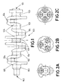
- Figure 1 shows an example of a crankshaft 100, with a flange side 101 and a pulley side 102, with the main journals 103, crankpin journals 104, and counterweights 105.
- the crankpin journals may be distributed in different ways depending on the type of engine. For example, figure 2A shows a 180° layout, figure 2B a 120° layout, and figure 2C a layout at 90°.
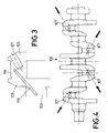
- Figure 3 schematically illustrates a close-up of one of the lightening holes 107 of the crankshaft, which has been drilled in order to remove internal material from the crank pin 104 and, therefore, in order to reduce the weight of the crankshaft.
- the location and direction of the lightening holes 107 are important given that, for example, they can give rise to a higher risk of fractures, especially in critical points such as in zones close to the lubrication holes 106.
- the location and orientation of lightening holes 107 need to be calculated carefully. Consequently, as shown schematically in figure 4 , a crankshaft may have multiple lightening holes 107, running in different directions.
- the machining of this type of multiple holes requires machines that allow the elements for machining to be positioned appropriately in respect to the machining tools, and that allow the machining tools to access the zones to be machined without encountering any obstacles. For example, it may be necessary to position the crankshaft in such a way that the direction of the hole to be drilled coincides with the direction of the corresponding machining spindle.
- crankshaft is often held by its ends by devices that are arranged for rotating the crankshaft, cf., for example, US-6203478-B1 , EP-0397049-A2 , and DE-19749939-A1 .
- these devices or parts of them are sometimes arranged to allow for a certain axial displacement, basically, in parallel with the longitudinal axis of the crankshaft, as in the case of DE-19749939-A2 , the crankshaft remains supported by its ends, and the elements interacting with the ends of the crankshaft can thus render access to certain portions of the crankshaft difficult, especially from certain angles.
- a first aspect of the invention relates to a machine for machining crankshafts, for example, for making lightening holes in crankshafts, and/or for other stages of crankshaft machining, such as the machining of the flange and shaft.
- the machine comprises:
- the support is turning in respect to a vertical axis in such a way that an angle of attack can be modified between the longitudinal axis of the crankshaft (passing through its main journals) and the actuator and/or the corresponding tool for making lightening holes.
- the support is provided with a turning mechanism displaceable between a retracted position in which it does not interact with the crankshaft, and an actuation position wherein the turning mechanism interacts with the crankshaft, for example, with one end of the crankshaft, in order to turn the crankshaft in respect to said longitudinal axis.
- the support can be turned in order to modify the angle of attack between the tool and the longitudinal axis of the crankshaft, and to turn the crankshaft about its longitudinal axis, so as to position the hole in the appropriate position, without needing to turn the actuator, which can be displaceable in three orthogonal directions following the X, Y and Z axes, as is conventional in many machine tools.
- the turning mechanism is displaceable between its retracted position and its actuation position, the turning mechanism can be retracted so as not to present an obstacle for the tool's access to the crankshaft. Furthermore, given that both ends of the crankshaft can remain freely accessible, it is also possible to machine the flange and shaft of the crankshaft, without the turning mechanism being an impediment for this function.
- the lightening holes are made on a rough and inclined surface, which may require a prior operation of surface preparation.
- the machine may be provided with a tool store and an automatic system for changing the tools on the tool actuators, for example, on the spindles, in order to take care of said prior preparation operations and/or the drilling of the holes of different dimensions.
- the turning mechanism is mounted on the support in such a way that it can be displaced linearly between said retracted position and said actuation position.
- This allows a very simple configuration, whereby the turning mechanism can be displaced linearly, between the retracted position wherein the end of the crankshaft is left free and does not represent an obstacle for the tool's access to the crankshaft, and the actuation position wherein it acts on the crankshaft, for example, on the end of the crankshaft, to turn it about its longitudinal axis.
- the turning mechanism may be mounted on the support in such a way that it is displaceable horizontally between said retracted position and said actuation position, which would allow for an especially simple and practical design of the machine.
- the turning mechanism may comprise a carriage that moves between said positions, guided on the support and driven by, for example, the turning of a spindle or similar.
- the turning mechanism is mounted on the support in such a way that it is displaceable between said retracted position and said actuation position in a direction perpendicular to a longitudinal axis of the crankshaft.
- the turning mechanism can be easily and rapidly withdrawn from the area facing the end of the crankshaft, thereby facilitating accessibility to the crankshaft, including its ends, from different angles.
- the turning mechanism is mounted on the support in such a way that it is displaceable following a curved trajectory between said retracted position and said actuation position.
- This may also allow for a simple configuration, whereby the turning mechanism can displace angularly pivoting about an axis, for example, about a horizontal or vertical axis, between the retracted position wherein the end of the crankshaft is left free and does not represent an obstacle for the tool's access to the crankshaft, and the actuation position wherein it acts on the crankshaft, for example, on the end of the crankshaft, in order to turn it.
- each clamping device comprises a self-centring vice with two jaws configured to displace simultaneously between an open position for loading and/or unloading the crankshaft, and a closed position of fastening the crankshaft.
- This type of self-centring vice allows easy and correct positioning of the crankshaft in the machine, in such a way that the position of the crankshaft is clearly defined by the clamping devices.
- the machine comprises at least one angular positioning device, in order to guarantee that the crankshaft is placed correctly with regard to the position of its eccentric parts in respect to the longitudinal axis, in other words, in order to guarantee, for example, that the crankpin journals are correctly positioned.
- each positioning device comprises two positioning members, for example, two claws or jaws, arranged so as to pivot between a first closed position, wherein said positioning members clamp between them a crankpin journal of the crankshaft, and an open position wherein said positioning members allow the crankshaft to turn on its longitudinal axis, without preventing said turning through contact with the crankpin journals.
- the positioning members are a positioning device with a large opening, wherein the positioning members can be separated or opened so much that they do not prevent the turning of the crankshaft on its longitudinal axis.
- the pivoting of the positioning members which may be two claws or jaws, the need to provide the angular positioning device with a retractable movement is avoided; it can simply be opened and closed, something that gives rise to a simpler structure, more economical and with less risk of breakdowns.
- At least one of said clamping devices is displaceable in a direction parallel to the longitudinal axis of the crankshaft, in such a way that it is possible to adapt the distance between said clamping devices, and/or the position of said clamping devices in respect to the turning mechanism and/or in respect to a reference point on the support, in order to adapt the machine to different types of crankshafts. This makes it possible to increase the machine's flexibility.
- the support is configured to secure at least two crankshafts, one on top of the other.
- two tool actuators or spindles disposed one on top of the other, it is possible to act simultaneously on the two crankshafts.
- the vertical disposition of the crankshafts in other words, one on top of the other (instead of one next to the other on the same horizontal plane)
- a crankshaft does not impede access of one of the tools to the other crankshaft, for example, according to the angle of rotation of the support in respect to the vertical axis.
- the tools have the same ease of access to both crankshafts, and it is never easier to access one of the crankshafts over the other.
- crankshafts next to each other on the same horizontal plane, wherein one of the crankshafts can block access to the other one. Plus, if the crankshafts are disposed on the same horizontal plane next to each other, upon turning the support of the crankshafts in respect to its vertical axis the distance would vary between the lightening holes for machining, whereupon the lightening holes of the at least two crankshafts could not be machined simultaneously.
- the support is configured to hold said, at least two, crankshafts, one on top of the other and oriented horizontally, above a space for receiving chips.
- crankshafts instead of having the crankshafts supported on a table, in parallel and on the same horizontal plane, they can be arranged one on top of the other and above a space, such as a pit, for receiving chips.
- This space may be associated to some type of chips removal system, for example, a conveyor belt or similar in order to prevent the accumulation of chips in one place.
- the parts that may come into contact with chips may be, for example, made of stainless steel, in order to reduce the risk of the chips adhering to the machinery.
- the actuator is disposed in order to actuate a machining tool to machine one of said crankshafts, and the machine comprises additionally at least one other actuator disposed to act on a machining tool to machine another of said crankshafts.
- Both actuators may be axially displaceable independently of each other.
- each actuator or spindle can displace axially independently of the other one, which increases flexibility and allows compensation of errors in the positioning of the elements, or errors and tolerances in tool dimensions, etc.
- one of the crankshafts can be machined differently to the other one, something which may be of interest, for example, in order to provide the two crankshafts with different traceability markings.
- the machine comprises at least one additional element which is displaceable between an actuation position wherein the additional element interacts with the crankshaft, and a retracted position wherein it does not interact with the crankshaft, the additional element preferably being mounted on the support in such a way that it is displaceable between said retracted position and said actuation position, preferably in a linear manner.
- This additional element may be any tool or other device designed to interact with the crankshaft at some time in the process (for example, it may be a device for positioning and/or securing the crankshaft), and the fact that it can be retracted serves to facilitate the access of the other tools to the crankshaft, in the same way as retracting the turning mechanism serves this same purpose.
- the machine comprises an axial positioning system of the crankshaft, which may comprise one or more pushers and/or one or more stoppers or counterpoints, in order to secure the axial position of the crankshaft in respect to a reference point, for example, a stopper.
- the additional element may be an axial positioning element that forms part of an axial positioning mechanism.
- the additional element may be a stopper against which the crankshaft can stop when it is in an appropriate reference position for machining, or a pusher or other element may displace the crankshaft axially, to a reference position.
- This axial positioning element (or other type of additional element) may therefore be displaceable between an actuation position wherein the axial positioning element interacts with the crankshaft (for example, facing one end of the crankshaft, for example, the end opposite the end with which the turning mechanisms interacts), and a retracted position wherein it does not interact with the crankshaft.
- the additional element (for example, an axial positioning element) is mounted on the support in such a way that it is displaceable, for example, linearly or following a curved trajectory, between said retracted position and said actuation position.
- the additional element is mounted on a side of the support opposite the side of the support on which the turning mechanism is mounted.
- the turning mechanism may comprise a carriage and the additional element may be mounted on another carriage, and these carriages may be displaceable between the respective retracted and actuation positions, for example, following parallel trajectories.
- this mechanism may include other elements, for example, other pusher and/or stopper elements, which may be mounted on the support itself, and/or on the turning device, for example, in a way that is integrated with the actuator that is used to make the crankshaft turn, or separately from said actuator.
- the machine additionally comprises a system for loading and unloading crankshafts which includes a manipulator that is provided with, for each crankshaft that the support is configured to hold simultaneously, a first clamping assembly to carry a crankshaft to the support, and a second clamping assembly to remove a crankshaft from the support.
- the manipulator which, for example, may be a robot type manipulator or a gantry type manipulator, may approach the support with one, two or more crankshafts to be machined, collect the crankshafts already machined from the support, place the new crankshafts to be machined in the support, and retract with the crankshafts already machined. This allows a reduction in cycle times.
- the manipulator delivers already machined crankshafts and receives new crankshafts to be machined during the time that the crankshafts supported in the support are being machined, and each time it approaches the support it can collect all the machined crankshafts and load the new crankshafts for machining.
- each actuator or spindle for a tool is configured to displace in three orthogonal directions, in other words, following the X, Y and Z axes, as is conventional.
- crankshafts are clamped in the support with their longitudinal axis disposed horizontally.
- the turning mechanism is mounted on a side of the support, in such a way that it can be displaced in order to interact with one end of the crankshaft in said actuation position, to turn the crankshaft about its longitudinal axis.
- This configuration is very simple and practical.
- Another aspect of the invention relates to a method for machining a crankshaft, which comprises the step of disposing the crankshaft in the support of a machine according to any of the embodiments above, and orienting the crankshaft in respect to a machining spindle turning the support following a vertical axis, and turning the crankshaft about its longitudinal axis.
- the method may additionally comprise the step of making at least one lightening hole in the crankshaft.
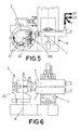
- Figures 5-7 reflect schematically how a machine according to a possible embodiment of the invention comprises a support 2 in the shape of a tower which can turn or pivot in respect to a vertical axis A.
- the support comprises two pairs of clamping devices 21 in order to secure respective crankshafts 100 holding them by two of their main journals (depending on the type of crankshaft, the crankshafts may be held by more main journals, for example, by three or more main journals).
- the clamping devices are disposed in two rows, one on top of the other, to clamp respective crankshafts 100, one on top of the other, with the longitudinal axis B of each crankshaft disposed horizontally.
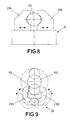
- Each clamping device 21 may have two jaws 21 A and 21 B which can displace simultaneously between an open position for loading and/or unloading the crankshaft, and a closed position clamping the crankshaft, as illustrated schematically in figure 8 .
- the jaws may have a self-centring configuration with inclined or curved surfaces so that when the jaws close, the crankshaft is disposed with its longitudinal axis B in a well-defined position.
- the machine comprises a frame 11 on which two spindles 1 are disposed to actuate respective tools, for example tools for drilling lightening holes.
- These spindles are displaceable following two horizontal perpendicular axes and following one vertical axis, in other words, following the four axes, X, Y and Z1/Z2, in other words, each spindle 1 can displace axially independently of the other one, which increases flexibility and allows for compensation for errors in the positioning of the elements, due to errors and tolerances in tool dimensions, etc.
- it makes it possible to machine the crankshafts in different ways from each other, something that may be of interest, for example, for providing the two crankshafts with different traceability markings.
- the positioning between the crankshafts 100 and the spindles 1 may vary according to five degrees of freedom, namely, three degrees of freedom corresponding to the linear displacement of the spindles following four axes X, Y and Z1/Z2, and two degrees of freedom corresponding to the turning of the support following the vertical axis A, and the turning of the crankshaft on its longitudinal axis B.
- the machine comprises a turning mechanism 22 which is mounted on a side of the support, in such a way that it can be displaced, following the arrow illustrated in figures 5 and 6 , between a retracted position wherein it does not interact with the crankshaft 100, and an actuation position wherein the turning mechanism 22 interacts with the crankshaft 100 in order to turn the crankshaft 100 in respect to said longitudinal axis B.
- the turning mechanism comprises on the one part a carriage 22A that can displace horizontally driven by actuator means and guided by a system of guides which have not been illustrated in detail, and on the other part an actuator 22B that can connect with the end of the crankshaft to turn it, in a controlled manner.
- the machine comprises, in correspondence with each crankshaft and as may be observed in figures 7 , 9 and 10 , an angular positioning device 23 which comprises two positioning members 23A and 23B disposed to pivot between a first closed position, wherein said positioning members 23A and 23B grip between them a crankpin journal 104 of the crankshaft as may be observed in figure 9 , and an open position wherein said positioning members 23A and 23B allow the turning of the crankshaft about its longitudinal axis without preventing said turning through contact with the crankpin journals, as indicated by the dashed lines in figure 9 .
- it is a positioning device with a large opening, wherein the positioning members can be separated or opened so much that they do not prevent the turning of the crankshaft. This avoids the need to provide the positioning device 23 with a movement of retraction; it can simply open and close.
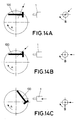
- crankshaft With this machine and with the spindles 1 displaceable linearly following three orthogonal axes, it is possible to position the crankshaft correctly in respect to the spindle in order to make a lightening hole, as illustrated in figures 14A-14C .
- the straight arrows illustrate the desired direction of the hole to be drilled.
- the crankshaft is turned on its longitudinal axis B (the step from figure 14A to figure 14B ) and the support is turned on its vertical axis A (step from figure 14B to figure 14C ).
- these two steps can be carried out in any order, simultaneously or one after the other.
- Figure 10 illustrates schematically how one of the clamping devices 22 is displaceable in parallel with the longitudinal axis of the crankshaft, in other words, horizontally, to allow the machine to be adapted easily to a different type of crankshaft (illustrated with a dashed line, like the new position of the clamping device). In some embodiments of the invention, more than one of the clamping devices is displaceable in this way.
- Figure 11 illustrates how, in accordance with a possible embodiment of the invention, the two crankshafts 100 can be disposed one on top of the other, each with its longitudinal axis oriented horizontally, on one side of the support 2, in such a way that the chips which are generated during machining fall to a pit 30 for collecting chips, from where they can be conveyed through a chips removal system 31 to prevent an excessive accumulation of the chips.
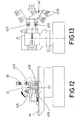
- Figures 12 and 13 illustrate, schematically, how the machine can comprise a system for loading and unloading crankshafts which includes a manipulator 41, 42 that is provided with, for each crankshaft that the support is configured to hold simultaneously, a first clamping assembly 41 A, 42A to carry a crankshaft to the support 2, and a second clamping assembly 41 B, 42B to remove a crankshaft from the support.
- the manipulator is displaceable linearly across the length of a frame 44 and can pivot following a horizontal axis 45, in such a way that it can receive two crankshafts from above as illustrated in figure 12 , which are clamped by the jaws of the first clamping assembly 41 A.
- the manipulator turns 90 degrees in a clockwise direction, following the horizontal axis 45, and displaces linearly towards the support 2.
- the jaws of the second clamping assembly 41 B collect the crankshafts that are in the support, already machined.
- the manipulator 41 turns 180 degrees on the horizontal axis 45 to place the first clamping assembly 41 A opposite the support, in order to load the new crankshafts to be machined in the support.
- the manipulator retracts to unload the machined crankshafts and to receive new crankshafts for machining, it being possible to carry out this loading and unloading operation at the same time as the crankshafts mounted on the support are machined.
- Figure 13 illustrates an alternative wherein instead of a manipulator mounted on a frame such as the one illustrated in figure 12 , the manipulator 42 is mounted on a robotic arm.
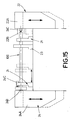
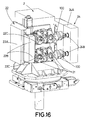
- Figures 15 and 16 illustrate an alternative embodiment, wherein in addition to the carriage 22A there is a second carriage 24A, mounted on the side of the support 2 opposite the side on which carriage 22A is mounted.
- an axial positioning element 24B is mounted (in other embodiments of the invention it may be another type of device, for example, a tool or similar, or a device for positioning and/or securing the part to be machined) which serves to position the crankshaft correctly in its axial direction, or any other device that it may be necessary to retract so as not to interfere with the machining.
- This axial positioning element 24B may be a stopper or counterpoint, against which the crankshaft can be pushed by means of the use of one or more pushers 24C, which may be mounted on the support itself or similar, and/or in the carriage 22A of the turning mechanism, as illustrated schematically in figure 15 .
- the axial positioning element 24B may be a pusher or similar.
- the carriages 22A and 24A are both displaceable linearly between their respective actuation positions (wherein the actuator 22B and the axial positioning element 24B interact with the crankshaft to turn it and to act as a stopper, respectively) and their respective retracted positions, wherein they do not prevent access of the tools of the actuators 1 to the crankshaft, from different positions and angles.
- FIG 16 it is also possible to observe schematically the jaws 22C that form part of the turning mechanism 22.
- the invention is not limited to the specific embodiments described but also encompasses, for example, variants that may be embodied by the average person skilled in the art (for example, in terms of the choice of materials, dimensions, components, configuration, etc.), within the scope of what can be inferred from the claims.
Landscapes
- Engineering & Computer Science (AREA)
- Mechanical Engineering (AREA)
- Turning (AREA)
- Jigs For Machine Tools (AREA)
- Milling Processes (AREA)
- Shafts, Cranks, Connecting Bars, And Related Bearings (AREA)
- Drilling And Boring (AREA)
Claims (17)
- Maschine zur Bearbeitung von Kurbelwellen, welche aufweist:eine Stütze (2) zum Stützen mindestens einer Kurbelwelle (100);mindestens einen Aktuator (1) zum Betätigen eines Bearbeitungswerkzeugs zur Bearbeitung der Kurbelwelle;wobei die Stütze (2) dazu ausgebildet ist, die mindestens eine Kurbelwelle unter Verwendung mindestens zweier Klemmvorrichtungen (21) zu halten;wobei die Stütze (2) in Bezug auf eine vertikale Achse (A) drehbar ist, um einen Angriffswinkel zwischen einer Längsachse (B) der Kurbelwelle (100) und dem Aktuator (1) zu verändern;dadurch gekennzeichnet, dassdie mindestens zwei Klemmvorrichtungen (21) derart ausgebildet sind, dass sie die Kurbelwelle entsprechend mindestens zweier Hauptzapfen (103) der Kurbelwelle halten;und dassdie Stütze mit einem Drehmechanismus (22) versehen ist, welcher zwischen einer zurückgezogenen Position, in welcher er nicht mit der Kurbelwelle (100) interagiert, und einer Betätigungsposition bewegbar ist, in welcher der Drehmechanismus (22) mit der Kurbelwelle (100) interagiert, um die Kurbelwelle (100) in Bezug auf die Längsachse (B) zu drehen.
- Maschine nach Anspruch 1, bei welcher der Drehmechanismus (22) an der Stütze (2) derart angebracht ist, dass er linear zwischen der zurückgezogenen Position und der Betätigungsposition bewegbar ist.
- Maschine nach Anspruch 2, bei welcher der Drehmechanismus (22) an der Stütze (2) derart angebracht ist, dass er horizontal zwischen der zurückgezogenen Position und der Betätigungsposition bewegbar ist.
- Maschine nach einem der vorhergehenden Ansprüche, bei welcher der Drehmechanismus (22) an der Stütze (2) derart angebracht ist, dass er zwischen der zurückgezogenen Position und der Betätigungsposition in einer zur Längsachse der Kurbelwelle senkrechten Richtung bewegbar ist.
- Maschine nach Anspruch 1, bei welcher der Drehmechanismus (22) an der Stütze (2) derart angebracht ist, dass er entlang einer gebogenen Bahn zwischen der zurückgezogenen Position und der Betätigungsposition bewegbar ist.
- Maschine nach einem der vorhergehenden Ansprüche, bei welcher der Drehmechanismus (22) derart angeordnet ist, dass, wenn er sich in der zurückgezogenen Position befindet, das entsprechende Ende der Kurbelwelle für das Bearbeitungswerkzeug frei zugängig ist.
- Maschine nach einem der vorhergehenden Ansprüche, bei welcher die Klemmvorrichtung (21) eine selbstzentrierende Schraubzwinge mit zwei Backen (21A, 21B) aufweist, welche derart ausgebildet sind, dass sie gleichzeitig zwischen einer offenen Position zum Einsetzen und/oder Entnehmen der Kurbelwelle und einer die Kurbelwelle klemmenden geschlossenen Position bewegbar sind.
- Maschine nach einem der vorhergehenden Ansprüche, welche zusätzlich mindestens eine Winkelpositionierungsvorrichtung (23) aufweist, welche zwei Positionierungselemente (23A, 23B) aufweist, welche zwischen einer ersten, geschlossenen Position, in welcher die Positionierungselemente (23A, 23B) zwischen einander einen Kurbelwellenzapfen (104) der Kurbelwelle greifen, und einer offenen Position, in welcher die Positionierungselemente (23A, 23B) der Kurbelwelle das Drehen um deren Längsachse ermöglichen, verschwenkbar angeordnet sind.
- Maschine nach einem der vorhergehenden Ansprüche, bei welcher mindestens eine der Klemmvorrichtungen (21) in eine parallel zur Längsachse (B) der Kurbelwelle verlaufende Richtung derart bewegbar ist, dass es möglich ist, die Entfernung zwischen den Klemmvorrichtungen (21) einzustellen, um die Maschine an verschiedene Arten von Kurbelwellen anzupassen.
- Maschine nach einem der vorhergehenden Ansprüche, bei welcher die Stütze (2) derart ausgebildet ist, dass sie mindestens zwei Kurbelwellen übereinander, vorzugsweise in horizontaler Ausrichtung, vorzugsweise über einem Raum (30) zum Aufnehmen von Spänen klemmend hält.
- Maschine nach Anspruch 10, bei welcher der Aktuator (1) zur Betätigung einer Werkzeugmaschine zur Bearbeitung einer der Kurbelwellen (100) angeordnet ist, wobei die Maschine zusätzlich mindestens einen weiteren Aktuator (1) aufweist, welcher zur Betätigung einer Werkzeugmaschine zur Bearbeitung der anderen Kurbelwelle (100) angeordnet ist, wobei beide Aktuatoren unabhängig voneinander axial bewegbar (Z1/Z2) sind.
- Maschine nach einem der vorhergehenden Ansprüche, welche mindestens ein zusätzliches Element (24B) aufweist, welches zwischen einer Betätigungsposition, in welcher das zusätzliche Element (24B) mit der Kurbelwelle interagiert, und einer zurückgezogenen Position, in welcher es nicht mit der Kurbelwelle interagiert, bewegbar ist, wobei das zusätzliche Element (24B) an der Stütze (2) vorzugsweise derart angebracht ist, dass es zwischen der zurückgezogenen Position und der Betätigungsposition vorzugsweise linear bewegbar ist.
- Maschine nach Anspruch 12, welche einen Axialpositionierungsmechanismus (24) für die Kurbelwelle aufweist, wobei das mindestens eine zusätzliche Element (24B) ein Axialpositionierungselement (24B) ist, das Teil des Axialpositionierungsmechanismus (24) ist.
- Maschine nach Anspruch 12 oder 13, bei welcher das zusätzliche Element (24B) auf einer ersten Seite der Stütze (2) angebracht ist, und wobei der Drehmechanismus (22) auf einer der ersten Seite gegenüberliegenden zweiten Seite der Stütze (2) angebracht ist, wobei der Drehmechanismus vorzugsweise einen Schlitten (22A) aufweist und das zusätzliche Element (24B) vorzugsweise an einem anderen Schlitte (24A) angebracht ist, wobei die Schlitten zwischen jeweiligen Rückzugs- und Betätigungspositionen bewegbar sind, wobei sie vorzugsweise parallelen Bahnen folgen.
- Maschine nach einem der vorhergehenden Ansprüche, welche zusätzlich ein System zum Einsetzen und Entnehmen von Kurbelwellen aufweist, welches einen Manipulator (41, 42) aufweist, der für jede Kurbelwelle, die gleichzeitig zu halten die Stütze ausgebildet ist, mit einer ersten Klemmanordnung (41A, 42A) versehen ist, um eine Kurbelwelle zu der Stütze (2) zu tragen, und mit einer zweiten Klemmanordnung (41B, 42B) versehen ist, um eine Kurbelwelle aus der Stütze (2) zu entnehmen.
- Maschine nach einem der vorhergehenden Ansprüche, bei welcher der Drehmechanismus (22) auf einer Seite der Stütze (2) derart angebracht ist, dass er bewegbar ist, um in der Betätigungsposition mit einem Ende der Kurbelwelle (100) zu Drehen der Kurbelwelle um deren Längsachse (B) zu interagieren.
- Verfahren zum Herstellen von Gewichtsverringerungslöchern in einer Kurbelwelle, mit dem Schritt des Platzierens der Kurbelwelle in der Stütze (2) einer Maschine nach einem der vorhergehenden Ansprüche, und dem Schritt des Ausrichtens der Kurbelwelle in Bezug auf eine Bearbeitungsspindel,- Drehen der Stütze (2) um eine vertikale Achse (A), und- Drehen der Kurbelwelle um eine Längsachse (B),
wobei das Verfahren den zusätzlichen Schritt des Ausbildens mindestens eines Gewichtsverringerungslochs in der Kurbelwelle aufweist.
Priority Applications (2)
| Application Number | Priority Date | Filing Date | Title |
|---|---|---|---|
| EP14169144.4A EP2805794B1 (de) | 2013-05-24 | 2014-05-20 | Maschine zur Bearbeitung von Kurbelwellen |
| SI201430021A SI2805794T1 (sl) | 2013-05-24 | 2014-05-20 | Stroj za obdelavo ročičnih gredi |
Applications Claiming Priority (2)
| Application Number | Priority Date | Filing Date | Title |
|---|---|---|---|
| EP13382190 | 2013-05-24 | ||
| EP14169144.4A EP2805794B1 (de) | 2013-05-24 | 2014-05-20 | Maschine zur Bearbeitung von Kurbelwellen |
Publications (2)
| Publication Number | Publication Date |
|---|---|
| EP2805794A1 EP2805794A1 (de) | 2014-11-26 |
| EP2805794B1 true EP2805794B1 (de) | 2016-03-02 |
Family
ID=48874238
Family Applications (1)
| Application Number | Title | Priority Date | Filing Date |
|---|---|---|---|
| EP14169144.4A Active EP2805794B1 (de) | 2013-05-24 | 2014-05-20 | Maschine zur Bearbeitung von Kurbelwellen |
Country Status (11)
| Country | Link |
|---|---|
| US (1) | US9333560B2 (de) |
| EP (1) | EP2805794B1 (de) |
| KR (1) | KR102240343B1 (de) |
| CN (1) | CN104174891B (de) |
| BR (1) | BR102014012343B1 (de) |
| CA (1) | CA2852206C (de) |
| ES (1) | ES2574486T3 (de) |
| IN (1) | IN2014DE01354A (de) |
| MX (1) | MX349078B (de) |
| RU (1) | RU2672129C2 (de) |
| SI (1) | SI2805794T1 (de) |
Families Citing this family (26)
| Publication number | Priority date | Publication date | Assignee | Title |
|---|---|---|---|---|
| CA2852206C (en) * | 2013-05-24 | 2020-07-21 | Ernesto Cano | Machine for machining crankshafts |
| DE102015111468A1 (de) * | 2015-07-15 | 2017-01-19 | Gebr. Heller Maschinenfabrik Gmbh | Bearbeitungsmaschine mit neuartiger Werkstückbeladeeinrichtung |
| DE102017107301B4 (de) * | 2017-04-05 | 2019-01-24 | Man Diesel & Turbo Se | Vorrichtung und Verfahren zum Bearbeiten von Gegengewichtsbohrungen an einer Kurbelwelle einer Brennkraftmaschine |
| CN108672734A (zh) * | 2018-05-18 | 2018-10-19 | 中船黄埔文冲船舶有限公司 | 一种船舶连接轴法兰孔的加工方法及工装装置 |
| DE102018113324A1 (de) | 2018-06-05 | 2019-12-05 | Gebr. Heller Maschinenfabrik Gmbh | Werkzeugmaschine und Verfahren zum Einrichten derselben |
| CN109465656A (zh) * | 2018-11-15 | 2019-03-15 | 山东华宇工学院 | 一种数控机床的夹紧装置 |
| CN109352384A (zh) * | 2018-11-20 | 2019-02-19 | 浙江金汤机床有限公司 | 曲轴加工机床 |
| CN111014790B (zh) * | 2019-12-27 | 2024-08-02 | 广东合和建筑五金制品有限公司 | 一种执手齿轮全自动化切削加工装置 |
| IT202000001789A1 (it) * | 2020-01-30 | 2021-07-30 | Paolino Bacci Srl | Un tornio multi-mandrino a controllo numerico |
| CN112024924B (zh) * | 2020-08-25 | 2024-08-23 | 浙江信戈制冷设备科技有限公司 | 一种工件内涨夹紧机构 |
| WO2022042901A1 (en) | 2020-08-28 | 2022-03-03 | Etxe-Tar, S.A. | Machine tool |
| CN112705747B (zh) * | 2020-12-31 | 2024-08-23 | 镇江市高等专科学校 | 一种数控曲轴车床卡具 |
| CN112692330B (zh) * | 2020-12-31 | 2024-07-23 | 江苏罡阳股份有限公司 | 一种摩托车曲轴用多工位打孔装置及其方法 |
| CN112872439B (zh) * | 2021-01-18 | 2022-06-10 | 山西东鑫衡隆机械制造股份有限公司 | 一种汽车曲轴加工用铣孔装置 |
| CN112975504A (zh) * | 2021-03-02 | 2021-06-18 | 沈阳机床股份有限公司 | 数控铣端面钻中心孔机床的曲轴定位机构 |
| CN113478259B (zh) * | 2021-07-20 | 2022-04-22 | 广州市德奥模具有限公司 | 一种多工位曲轴治具及曲轴组件的装配方法 |
| CN113894600A (zh) * | 2021-10-25 | 2022-01-07 | 威海天润智能科技有限公司 | 曲轴自动旋转装置 |
| CN113941883A (zh) * | 2021-10-25 | 2022-01-18 | 葫芦岛莲花山铸造有限公司 | 数控车床用铣削工件的固定装置 |
| CN114309712A (zh) * | 2021-12-31 | 2022-04-12 | 重庆化工职业学院 | 一种法兰加工用智能钻孔设备的动力装置 |
| CN114473915A (zh) * | 2022-03-01 | 2022-05-13 | 江苏贺颖智能科技有限公司 | 一种轴类零件转角定位机构 |
| CN115090926B (zh) * | 2022-07-13 | 2025-03-07 | 上海船用曲轴有限公司 | 一种船用曲轴拼接方法 |
| KR102513002B1 (ko) * | 2022-11-17 | 2023-03-21 | 정성래 | 편심크랭크샤프트의 위상고정장치 |
| CN116079618B (zh) * | 2023-01-09 | 2025-11-14 | 杭州铭赫科技有限公司 | 一种多穴位异形薄壁类产品的夹持工装 |
| CN117548698B (zh) * | 2024-01-12 | 2024-03-12 | 无锡煤矿机械股份有限公司 | 一种喷雾泵加工装置 |
| CN117884917B (zh) * | 2024-03-15 | 2024-05-14 | 江苏联星机械科技有限公司 | 一种曲轴加工用机床定位装置 |
| CN117943568B (zh) * | 2024-03-27 | 2024-06-11 | 四川飞亚动力科技股份有限公司 | 一种曲轴加工车削机床 |
Family Cites Families (22)
| Publication number | Priority date | Publication date | Assignee | Title |
|---|---|---|---|---|
| US2138522A (en) * | 1936-05-16 | 1938-11-29 | Leblond Mach Tool Co R K | Four-spindle drum type crankshaft lathe |
| US2174084A (en) * | 1938-04-04 | 1939-09-26 | Leblond Mach Tool Co R K | Station type pin and line bearing lathe |
| US2291035A (en) * | 1940-07-06 | 1942-07-28 | Leblond Mach Tool Co R K | Multiple spindle indexing crankpin lathe |
| US2264458A (en) * | 1940-08-20 | 1941-12-02 | Leblond Mach Tool Co R K | Vertical crank pin lathe |
| US2280230A (en) * | 1940-09-17 | 1942-04-21 | Leblond Mach Tool Co R K | Crankshaft broaching lathe |
| US2299290A (en) * | 1940-11-15 | 1942-10-20 | Gen Machinery Corp | Journal turning, quartering, and crank pin turning machine |
| US3621753A (en) * | 1969-09-11 | 1971-11-23 | Giddings & Lewis | Double trunnion accessory for milling machines |
| DE2209622B2 (de) * | 1972-02-29 | 1974-06-12 | Gebrueder Boehringer Gmbh, 7320 Goeppingen | Maschine zum Wirbeln einer Kurbelwelle |
| US4528876A (en) * | 1983-05-11 | 1985-07-16 | Crankshaft Machine Company | Universal single spindle pin crankshaft lathe |
| SU1288026A1 (ru) * | 1985-09-17 | 1987-02-07 | Московское Специальное Конструкторское Бюро Автоматических Линий И Агрегатных Станков | Агрегатный станок |
| JP2686141B2 (ja) | 1989-05-07 | 1997-12-08 | 豊田工機株式会社 | 位相割出し方法 |
| DE19749939C2 (de) * | 1997-11-11 | 2003-10-23 | Boehringer Werkzeugmaschinen | Verfahren zur Bearbeitung von Werkstücken |
| DE19828239A1 (de) * | 1998-06-25 | 2000-01-13 | Hegenscheidt Mfd Gmbh | Vorrichtung zum spanabhebenden Bearbeiten von Werkstücken |
| ES2167146B1 (es) * | 1999-04-19 | 2003-11-01 | Etxetar Sa | Maquina para taladrar agujeros de engrase en cigueñales y procedimiento correspondiente. |
| JP4024051B2 (ja) * | 2002-02-06 | 2007-12-19 | コマツ工機株式会社 | クランクシャフトの旋削加工装置 |
| CN2654261Y (zh) * | 2003-06-12 | 2004-11-10 | 南京汽车集团有限公司 | 轴类端面群孔加工专用机床 |
| CN2647476Y (zh) * | 2003-07-03 | 2004-10-13 | 机科发展科技股份有限公司 | 曲轴中心孔修正机 |
| RU2273548C1 (ru) * | 2004-11-09 | 2006-04-10 | Государственное образовательное учреждение высшего профессионального образования Волгоградский государственный технический университет (ВолгГТУ) | Металлорежущий станок |
| DE102006014972B4 (de) * | 2005-12-20 | 2018-06-21 | Gebr. Heller Maschinenfabrik Gmbh | Kombiniertes Bearbeitungsverfahren und Bearbeitungseinrichtung |
| CN201227696Y (zh) * | 2008-06-15 | 2009-04-29 | 李建民 | 曲轴质量定心机主机 |
| RU2560478C2 (ru) * | 2011-06-17 | 2015-08-20 | Этксе-Тар, С.А. | Станок и способ механической обработки концов коленчатых валов |
| CA2852206C (en) * | 2013-05-24 | 2020-07-21 | Ernesto Cano | Machine for machining crankshafts |
-
2014
- 2014-05-16 CA CA2852206A patent/CA2852206C/en active Active
- 2014-05-19 RU RU2014119998A patent/RU2672129C2/ru active
- 2014-05-20 ES ES14169144.4T patent/ES2574486T3/es active Active
- 2014-05-20 SI SI201430021A patent/SI2805794T1/sl unknown
- 2014-05-20 EP EP14169144.4A patent/EP2805794B1/de active Active
- 2014-05-20 US US14/283,000 patent/US9333560B2/en active Active
- 2014-05-21 MX MX2014006112A patent/MX349078B/es active IP Right Grant
- 2014-05-22 IN IN1354DE2014 patent/IN2014DE01354A/en unknown
- 2014-05-22 CN CN201410219265.0A patent/CN104174891B/zh active Active
- 2014-05-22 BR BR102014012343-1A patent/BR102014012343B1/pt not_active IP Right Cessation
- 2014-05-26 KR KR1020140063298A patent/KR102240343B1/ko not_active Expired - Fee Related
Also Published As
| Publication number | Publication date |
|---|---|
| US20140345429A1 (en) | 2014-11-27 |
| KR20140138091A (ko) | 2014-12-03 |
| MX349078B (es) | 2017-07-07 |
| BR102014012343A2 (pt) | 2015-05-12 |
| MX2014006112A (es) | 2015-05-21 |
| CA2852206A1 (en) | 2014-11-24 |
| IN2014DE01354A (de) | 2015-06-12 |
| CN104174891B (zh) | 2018-03-06 |
| KR102240343B1 (ko) | 2021-04-15 |
| CN104174891A (zh) | 2014-12-03 |
| EP2805794A1 (de) | 2014-11-26 |
| ES2574486T3 (es) | 2016-06-20 |
| BR102014012343B1 (pt) | 2022-08-09 |
| US9333560B2 (en) | 2016-05-10 |
| CA2852206C (en) | 2020-07-21 |
| RU2672129C2 (ru) | 2018-11-12 |
| SI2805794T1 (sl) | 2016-07-29 |
| RU2014119998A (ru) | 2015-11-27 |
| BR102014012343A8 (pt) | 2021-04-20 |
Similar Documents
| Publication | Publication Date | Title |
|---|---|---|
| EP2805794B1 (de) | Maschine zur Bearbeitung von Kurbelwellen | |
| EP2812152B1 (de) | Honmaschine mit mehreren arbeitsstationen und rundtisch | |
| EP1604775B1 (de) | Speicheranordnung für Bearbeitungsmaschinen | |
| EP1334784B1 (de) | Verfahren und Vorrichtung zum Fügen von gebauten Hohlwellen | |
| EP2694245B1 (de) | Transportvorrichtung für eine längsachse aufweisende werkstücke | |
| EP3194114B1 (de) | Greifeinrichtung für ein bearbeitungswerkzeug, speichersystem sowie verfahren | |
| DE102018105025A1 (de) | Robotersystem mit rekonfigurierbarer endeffektor-baugruppe | |
| EP1364742B1 (de) | Werkzeughandhabungsvorrichtung für eine Werkzeugmaschine | |
| DE102009059659A1 (de) | Werkzeugmaschine mit Drehtisch und zusätzlicher Werkstückabstützung | |
| EP3338941B1 (de) | Rundtaktmaschine | |
| EP2881219B1 (de) | Werkzeugwechselvorrichtung zur Verwendung in einem Bearbeitungszentrum und Bearbeitungszentrum zur maschinellen Bearbeitung eines Werkstücks | |
| RU2560478C2 (ru) | Станок и способ механической обработки концов коленчатых валов | |
| EP1752255B1 (de) | Mehrspindeldrehmaschine mit Schwenkarmhandhabungseinrichtung | |
| EP3117954B1 (de) | Bearbeitungsmaschine mit werkstückbeladeeinrichtung | |
| EP2762253B1 (de) | Werkzeugmaschine zur Bearbeitung von Werkstücken | |
| EP3804930B1 (de) | Bearbeitungscenter mit be- und entladesystem für werkstücke, be- und entladesystem für werkstücke und zugehöriges verfahren zu dessen betrieb | |
| DE102012201044B4 (de) | Werkzeugmaschine mit zwei Arbeitsspindeln | |
| JP5624311B2 (ja) | 生産ラインおよび工作機械 | |
| DE112006003145T5 (de) | Zuführungsvorrichtung für ein Schneidwerkzeug zur Innenbearbeitung | |
| DE102007048083B4 (de) | Anordnung von Bearbeitungszonen | |
| KR20180109943A (ko) | 공작 기계 | |
| DE102011052976B4 (de) | Greifkopf zum Beschicken einer Schleifmaschine | |
| DE10336156B4 (de) | Bearbeitungsmaschine | |
| EP3969225A1 (de) | Vorrichtung zur honbearbeitung | |
| KR200260151Y1 (ko) | 파이프 챔퍼링머신 |
Legal Events
| Date | Code | Title | Description |
|---|---|---|---|
| PUAI | Public reference made under article 153(3) epc to a published international application that has entered the european phase |
Free format text: ORIGINAL CODE: 0009012 |
|
| 17P | Request for examination filed |
Effective date: 20140520 |
|
| AK | Designated contracting states |
Kind code of ref document: A1 Designated state(s): AL AT BE BG CH CY CZ DE DK EE ES FI FR GB GR HR HU IE IS IT LI LT LU LV MC MK MT NL NO PL PT RO RS SE SI SK SM TR |
|
| AX | Request for extension of the european patent |
Extension state: BA ME |
|
| R17P | Request for examination filed (corrected) |
Effective date: 20150216 |
|
| RBV | Designated contracting states (corrected) |
Designated state(s): AL AT BE BG CH CY CZ DE DK EE ES FI FR GB GR HR HU IE IS IT LI LT LU LV MC MK MT NL NO PL PT RO RS SE SI SK SM TR |
|
| GRAP | Despatch of communication of intention to grant a patent |
Free format text: ORIGINAL CODE: EPIDOSNIGR1 |
|
| RIC1 | Information provided on ipc code assigned before grant |
Ipc: B23B 41/12 20060101ALI20150918BHEP Ipc: B23Q 39/04 20060101AFI20150918BHEP Ipc: B23B 41/02 20060101ALI20150918BHEP |
|
| INTG | Intention to grant announced |
Effective date: 20151015 |
|
| GRAS | Grant fee paid |
Free format text: ORIGINAL CODE: EPIDOSNIGR3 |
|
| GRAA | (expected) grant |
Free format text: ORIGINAL CODE: 0009210 |
|
| AK | Designated contracting states |
Kind code of ref document: B1 Designated state(s): AL AT BE BG CH CY CZ DE DK EE ES FI FR GB GR HR HU IE IS IT LI LT LU LV MC MK MT NL NO PL PT RO RS SE SI SK SM TR |
|
| REG | Reference to a national code |
Ref country code: GB Ref legal event code: FG4D |
|
| REG | Reference to a national code |
Ref country code: AT Ref legal event code: REF Ref document number: 777668 Country of ref document: AT Kind code of ref document: T Effective date: 20160315 Ref country code: CH Ref legal event code: EP |
|
| REG | Reference to a national code |
Ref country code: IE Ref legal event code: FG4D |
|
| REG | Reference to a national code |
Ref country code: DE Ref legal event code: R096 Ref document number: 602014000991 Country of ref document: DE |
|
| REG | Reference to a national code |
Ref country code: ES Ref legal event code: FG2A Ref document number: 2574486 Country of ref document: ES Kind code of ref document: T3 Effective date: 20160620 |
|
| REG | Reference to a national code |
Ref country code: FR Ref legal event code: PLFP Year of fee payment: 3 |
|
| REG | Reference to a national code |
Ref country code: NL Ref legal event code: MP Effective date: 20160302 |
|
| REG | Reference to a national code |
Ref country code: LT Ref legal event code: MG4D |
|
| PG25 | Lapsed in a contracting state [announced via postgrant information from national office to epo] |
Ref country code: FI Free format text: LAPSE BECAUSE OF FAILURE TO SUBMIT A TRANSLATION OF THE DESCRIPTION OR TO PAY THE FEE WITHIN THE PRESCRIBED TIME-LIMIT Effective date: 20160302 Ref country code: HR Free format text: LAPSE BECAUSE OF FAILURE TO SUBMIT A TRANSLATION OF THE DESCRIPTION OR TO PAY THE FEE WITHIN THE PRESCRIBED TIME-LIMIT Effective date: 20160302 Ref country code: NO Free format text: LAPSE BECAUSE OF FAILURE TO SUBMIT A TRANSLATION OF THE DESCRIPTION OR TO PAY THE FEE WITHIN THE PRESCRIBED TIME-LIMIT Effective date: 20160602 Ref country code: GR Free format text: LAPSE BECAUSE OF FAILURE TO SUBMIT A TRANSLATION OF THE DESCRIPTION OR TO PAY THE FEE WITHIN THE PRESCRIBED TIME-LIMIT Effective date: 20160603 |
|
| PG25 | Lapsed in a contracting state [announced via postgrant information from national office to epo] |
Ref country code: LT Free format text: LAPSE BECAUSE OF FAILURE TO SUBMIT A TRANSLATION OF THE DESCRIPTION OR TO PAY THE FEE WITHIN THE PRESCRIBED TIME-LIMIT Effective date: 20160302 Ref country code: RS Free format text: LAPSE BECAUSE OF FAILURE TO SUBMIT A TRANSLATION OF THE DESCRIPTION OR TO PAY THE FEE WITHIN THE PRESCRIBED TIME-LIMIT Effective date: 20160302 Ref country code: SE Free format text: LAPSE BECAUSE OF FAILURE TO SUBMIT A TRANSLATION OF THE DESCRIPTION OR TO PAY THE FEE WITHIN THE PRESCRIBED TIME-LIMIT Effective date: 20160302 Ref country code: BE Free format text: LAPSE BECAUSE OF NON-PAYMENT OF DUE FEES Effective date: 20160531 Ref country code: PL Free format text: LAPSE BECAUSE OF FAILURE TO SUBMIT A TRANSLATION OF THE DESCRIPTION OR TO PAY THE FEE WITHIN THE PRESCRIBED TIME-LIMIT Effective date: 20160302 Ref country code: LV Free format text: LAPSE BECAUSE OF FAILURE TO SUBMIT A TRANSLATION OF THE DESCRIPTION OR TO PAY THE FEE WITHIN THE PRESCRIBED TIME-LIMIT Effective date: 20160302 Ref country code: NL Free format text: LAPSE BECAUSE OF FAILURE TO SUBMIT A TRANSLATION OF THE DESCRIPTION OR TO PAY THE FEE WITHIN THE PRESCRIBED TIME-LIMIT Effective date: 20160302 |
|
| PG25 | Lapsed in a contracting state [announced via postgrant information from national office to epo] |
Ref country code: EE Free format text: LAPSE BECAUSE OF FAILURE TO SUBMIT A TRANSLATION OF THE DESCRIPTION OR TO PAY THE FEE WITHIN THE PRESCRIBED TIME-LIMIT Effective date: 20160302 Ref country code: IS Free format text: LAPSE BECAUSE OF FAILURE TO SUBMIT A TRANSLATION OF THE DESCRIPTION OR TO PAY THE FEE WITHIN THE PRESCRIBED TIME-LIMIT Effective date: 20160702 |
|
| PG25 | Lapsed in a contracting state [announced via postgrant information from national office to epo] |
Ref country code: RO Free format text: LAPSE BECAUSE OF FAILURE TO SUBMIT A TRANSLATION OF THE DESCRIPTION OR TO PAY THE FEE WITHIN THE PRESCRIBED TIME-LIMIT Effective date: 20160302 Ref country code: SK Free format text: LAPSE BECAUSE OF FAILURE TO SUBMIT A TRANSLATION OF THE DESCRIPTION OR TO PAY THE FEE WITHIN THE PRESCRIBED TIME-LIMIT Effective date: 20160302 Ref country code: PT Free format text: LAPSE BECAUSE OF FAILURE TO SUBMIT A TRANSLATION OF THE DESCRIPTION OR TO PAY THE FEE WITHIN THE PRESCRIBED TIME-LIMIT Effective date: 20160704 Ref country code: SM Free format text: LAPSE BECAUSE OF FAILURE TO SUBMIT A TRANSLATION OF THE DESCRIPTION OR TO PAY THE FEE WITHIN THE PRESCRIBED TIME-LIMIT Effective date: 20160302 |
|
| REG | Reference to a national code |
Ref country code: DE Ref legal event code: R097 Ref document number: 602014000991 Country of ref document: DE |
|
| PG25 | Lapsed in a contracting state [announced via postgrant information from national office to epo] |
Ref country code: BE Free format text: LAPSE BECAUSE OF FAILURE TO SUBMIT A TRANSLATION OF THE DESCRIPTION OR TO PAY THE FEE WITHIN THE PRESCRIBED TIME-LIMIT Effective date: 20160302 Ref country code: LU Free format text: LAPSE BECAUSE OF FAILURE TO SUBMIT A TRANSLATION OF THE DESCRIPTION OR TO PAY THE FEE WITHIN THE PRESCRIBED TIME-LIMIT Effective date: 20160520 |
|
| PLBE | No opposition filed within time limit |
Free format text: ORIGINAL CODE: 0009261 |
|
| STAA | Information on the status of an ep patent application or granted ep patent |
Free format text: STATUS: NO OPPOSITION FILED WITHIN TIME LIMIT |
|
| PG25 | Lapsed in a contracting state [announced via postgrant information from national office to epo] |
Ref country code: DK Free format text: LAPSE BECAUSE OF FAILURE TO SUBMIT A TRANSLATION OF THE DESCRIPTION OR TO PAY THE FEE WITHIN THE PRESCRIBED TIME-LIMIT Effective date: 20160302 |
|
| 26N | No opposition filed |
Effective date: 20161205 |
|
| REG | Reference to a national code |
Ref country code: IE Ref legal event code: MM4A |
|
| PG25 | Lapsed in a contracting state [announced via postgrant information from national office to epo] |
Ref country code: BG Free format text: LAPSE BECAUSE OF FAILURE TO SUBMIT A TRANSLATION OF THE DESCRIPTION OR TO PAY THE FEE WITHIN THE PRESCRIBED TIME-LIMIT Effective date: 20160602 |
|
| REG | Reference to a national code |
Ref country code: FR Ref legal event code: PLFP Year of fee payment: 4 |
|
| PG25 | Lapsed in a contracting state [announced via postgrant information from national office to epo] |
Ref country code: IE Free format text: LAPSE BECAUSE OF NON-PAYMENT OF DUE FEES Effective date: 20160520 |
|
| REG | Reference to a national code |
Ref country code: CH Ref legal event code: PL |
|
| PG25 | Lapsed in a contracting state [announced via postgrant information from national office to epo] |
Ref country code: CH Free format text: LAPSE BECAUSE OF NON-PAYMENT OF DUE FEES Effective date: 20170531 Ref country code: LI Free format text: LAPSE BECAUSE OF NON-PAYMENT OF DUE FEES Effective date: 20170531 |
|
| REG | Reference to a national code |
Ref country code: FR Ref legal event code: PLFP Year of fee payment: 5 |
|
| PG25 | Lapsed in a contracting state [announced via postgrant information from national office to epo] |
Ref country code: HU Free format text: LAPSE BECAUSE OF FAILURE TO SUBMIT A TRANSLATION OF THE DESCRIPTION OR TO PAY THE FEE WITHIN THE PRESCRIBED TIME-LIMIT; INVALID AB INITIO Effective date: 20140520 |
|
| PG25 | Lapsed in a contracting state [announced via postgrant information from national office to epo] |
Ref country code: CY Free format text: LAPSE BECAUSE OF FAILURE TO SUBMIT A TRANSLATION OF THE DESCRIPTION OR TO PAY THE FEE WITHIN THE PRESCRIBED TIME-LIMIT Effective date: 20160302 Ref country code: MT Free format text: LAPSE BECAUSE OF NON-PAYMENT OF DUE FEES Effective date: 20160531 Ref country code: MK Free format text: LAPSE BECAUSE OF FAILURE TO SUBMIT A TRANSLATION OF THE DESCRIPTION OR TO PAY THE FEE WITHIN THE PRESCRIBED TIME-LIMIT Effective date: 20160302 Ref country code: MC Free format text: LAPSE BECAUSE OF FAILURE TO SUBMIT A TRANSLATION OF THE DESCRIPTION OR TO PAY THE FEE WITHIN THE PRESCRIBED TIME-LIMIT Effective date: 20160302 |
|
| REG | Reference to a national code |
Ref country code: AT Ref legal event code: UEP Ref document number: 777668 Country of ref document: AT Kind code of ref document: T Effective date: 20160302 |
|
| PG25 | Lapsed in a contracting state [announced via postgrant information from national office to epo] |
Ref country code: TR Free format text: LAPSE BECAUSE OF FAILURE TO SUBMIT A TRANSLATION OF THE DESCRIPTION OR TO PAY THE FEE WITHIN THE PRESCRIBED TIME-LIMIT Effective date: 20160302 Ref country code: AL Free format text: LAPSE BECAUSE OF FAILURE TO SUBMIT A TRANSLATION OF THE DESCRIPTION OR TO PAY THE FEE WITHIN THE PRESCRIBED TIME-LIMIT Effective date: 20160302 |
|
| REG | Reference to a national code |
Ref country code: DE Ref legal event code: R082 Ref document number: 602014000991 Country of ref document: DE Representative=s name: TERPATENT PARTGMBB, DE Ref country code: DE Ref legal event code: R082 Ref document number: 602014000991 Country of ref document: DE Representative=s name: TERPATENT PATENTANWAELTE TER SMITTEN EBERLEIN-, DE |
|
| PGFP | Annual fee paid to national office [announced via postgrant information from national office to epo] |
Ref country code: FR Payment date: 20230224 Year of fee payment: 10 |
|
| PGFP | Annual fee paid to national office [announced via postgrant information from national office to epo] |
Ref country code: GB Payment date: 20230331 Year of fee payment: 10 |
|
| P01 | Opt-out of the competence of the unified patent court (upc) registered |
Effective date: 20230530 |
|
| PGFP | Annual fee paid to national office [announced via postgrant information from national office to epo] |
Ref country code: IT Payment date: 20230519 Year of fee payment: 10 Ref country code: CZ Payment date: 20230509 Year of fee payment: 10 |
|
| PGFP | Annual fee paid to national office [announced via postgrant information from national office to epo] |
Ref country code: SI Payment date: 20230504 Year of fee payment: 10 Ref country code: AT Payment date: 20230504 Year of fee payment: 10 |
|
| PGFP | Annual fee paid to national office [announced via postgrant information from national office to epo] |
Ref country code: DE Payment date: 20240530 Year of fee payment: 11 |
|
| REG | Reference to a national code |
Ref country code: AT Ref legal event code: MM01 Ref document number: 777668 Country of ref document: AT Kind code of ref document: T Effective date: 20240520 |
|
| PG25 | Lapsed in a contracting state [announced via postgrant information from national office to epo] |
Ref country code: AT Free format text: LAPSE BECAUSE OF NON-PAYMENT OF DUE FEES Effective date: 20240520 |
|
| PG25 | Lapsed in a contracting state [announced via postgrant information from national office to epo] |
Ref country code: CZ Free format text: LAPSE BECAUSE OF NON-PAYMENT OF DUE FEES Effective date: 20240520 |
|
| GBPC | Gb: european patent ceased through non-payment of renewal fee |
Effective date: 20240520 |
|
| PG25 | Lapsed in a contracting state [announced via postgrant information from national office to epo] |
Ref country code: CZ Free format text: LAPSE BECAUSE OF NON-PAYMENT OF DUE FEES Effective date: 20240520 Ref country code: AT Free format text: LAPSE BECAUSE OF NON-PAYMENT OF DUE FEES Effective date: 20240520 |
|
| PG25 | Lapsed in a contracting state [announced via postgrant information from national office to epo] |
Ref country code: FR Free format text: LAPSE BECAUSE OF NON-PAYMENT OF DUE FEES Effective date: 20240531 |
|
| PG25 | Lapsed in a contracting state [announced via postgrant information from national office to epo] |
Ref country code: GB Free format text: LAPSE BECAUSE OF NON-PAYMENT OF DUE FEES Effective date: 20240520 Ref country code: IT Free format text: LAPSE BECAUSE OF NON-PAYMENT OF DUE FEES Effective date: 20240520 |
|
| PGFP | Annual fee paid to national office [announced via postgrant information from national office to epo] |
Ref country code: ES Payment date: 20250602 Year of fee payment: 12 |
|
| REG | Reference to a national code |
Ref country code: SI Ref legal event code: KO00 Effective date: 20240521 |
|
| REG | Reference to a national code |
Ref country code: DE Ref legal event code: R119 Ref document number: 602014000991 Country of ref document: DE |
|
| PG25 | Lapsed in a contracting state [announced via postgrant information from national office to epo] |
Ref country code: DE Free format text: LAPSE BECAUSE OF NON-PAYMENT OF DUE FEES Effective date: 20251202 |