EP2804748B1 - Manufacturing method of bag body with a granular filling - Google Patents
Manufacturing method of bag body with a granular filling Download PDFInfo
- Publication number
- EP2804748B1 EP2804748B1 EP13705006.8A EP13705006A EP2804748B1 EP 2804748 B1 EP2804748 B1 EP 2804748B1 EP 13705006 A EP13705006 A EP 13705006A EP 2804748 B1 EP2804748 B1 EP 2804748B1
- Authority
- EP
- European Patent Office
- Prior art keywords
- bag
- core
- shaped member
- manufacturing
- contact portion
- Prior art date
- Legal status (The legal status is an assumption and is not a legal conclusion. Google has not performed a legal analysis and makes no representation as to the accuracy of the status listed.)
- Not-in-force
Links
- 238000004519 manufacturing process Methods 0.000 title claims description 80
- 239000000126 substance Substances 0.000 claims description 66
- 239000011230 binding agent Substances 0.000 claims description 29
- 239000000203 mixture Substances 0.000 claims description 23
- 239000000463 material Substances 0.000 claims description 16
- 238000000465 moulding Methods 0.000 claims description 15
- 238000010438 heat treatment Methods 0.000 claims description 14
- 239000007788 liquid Substances 0.000 claims description 14
- XLYOFNOQVPJJNP-UHFFFAOYSA-N water Substances O XLYOFNOQVPJJNP-UHFFFAOYSA-N 0.000 claims description 14
- 239000007787 solid Substances 0.000 claims description 12
- 238000001816 cooling Methods 0.000 claims description 4
- 238000010298 pulverizing process Methods 0.000 claims description 3
- 238000000034 method Methods 0.000 description 13
- 229920001971 elastomer Polymers 0.000 description 12
- 239000005060 rubber Substances 0.000 description 12
- CURLTUGMZLYLDI-UHFFFAOYSA-N Carbon dioxide Chemical compound O=C=O CURLTUGMZLYLDI-UHFFFAOYSA-N 0.000 description 9
- 235000011089 carbon dioxide Nutrition 0.000 description 9
- 229910052500 inorganic mineral Inorganic materials 0.000 description 6
- 239000011707 mineral Substances 0.000 description 6
- 150000003839 salts Chemical class 0.000 description 6
- 229920000459 Nitrile rubber Polymers 0.000 description 5
- 235000019353 potassium silicate Nutrition 0.000 description 5
- 239000011347 resin Substances 0.000 description 5
- 229920005989 resin Polymers 0.000 description 5
- KZHJGOXRZJKJNY-UHFFFAOYSA-N dioxosilane;oxo(oxoalumanyloxy)alumane Chemical compound O=[Si]=O.O=[Si]=O.O=[Al]O[Al]=O.O=[Al]O[Al]=O.O=[Al]O[Al]=O KZHJGOXRZJKJNY-UHFFFAOYSA-N 0.000 description 4
- 239000003110 molding sand Substances 0.000 description 4
- 229910052863 mullite Inorganic materials 0.000 description 4
- 238000001746 injection moulding Methods 0.000 description 3
- 239000011248 coating agent Substances 0.000 description 2
- 238000000576 coating method Methods 0.000 description 2
- 238000001035 drying Methods 0.000 description 2
- 238000005516 engineering process Methods 0.000 description 2
- 230000008569 process Effects 0.000 description 2
- 239000002994 raw material Substances 0.000 description 2
- 241001391944 Commicarpus scandens Species 0.000 description 1
- BPQQTUXANYXVAA-UHFFFAOYSA-N Orthosilicate Chemical compound [O-][Si]([O-])([O-])[O-] BPQQTUXANYXVAA-UHFFFAOYSA-N 0.000 description 1
- CDBYLPFSWZWCQE-UHFFFAOYSA-L Sodium Carbonate Chemical compound [Na+].[Na+].[O-]C([O-])=O CDBYLPFSWZWCQE-UHFFFAOYSA-L 0.000 description 1
- 239000004115 Sodium Silicate Substances 0.000 description 1
- 229910000831 Steel Inorganic materials 0.000 description 1
- 230000003213 activating effect Effects 0.000 description 1
- 230000008859 change Effects 0.000 description 1
- 238000007710 freezing Methods 0.000 description 1
- 230000008014 freezing Effects 0.000 description 1
- 230000007246 mechanism Effects 0.000 description 1
- 238000002844 melting Methods 0.000 description 1
- 230000008018 melting Effects 0.000 description 1
- 239000005011 phenolic resin Substances 0.000 description 1
- NTHWMYGWWRZVTN-UHFFFAOYSA-N sodium silicate Chemical compound [Na+].[Na+].[O-][Si]([O-])=O NTHWMYGWWRZVTN-UHFFFAOYSA-N 0.000 description 1
- 229910052911 sodium silicate Inorganic materials 0.000 description 1
- 125000006850 spacer group Chemical group 0.000 description 1
- 239000010959 steel Substances 0.000 description 1
- 239000000057 synthetic resin Substances 0.000 description 1
- 229920003002 synthetic resin Polymers 0.000 description 1
Images


Classifications
-
- B—PERFORMING OPERATIONS; TRANSPORTING
- B29—WORKING OF PLASTICS; WORKING OF SUBSTANCES IN A PLASTIC STATE IN GENERAL
- B29B—PREPARATION OR PRETREATMENT OF THE MATERIAL TO BE SHAPED; MAKING GRANULES OR PREFORMS; RECOVERY OF PLASTICS OR OTHER CONSTITUENTS OF WASTE MATERIAL CONTAINING PLASTICS
- B29B11/00—Making preforms
- B29B11/02—Making preforms by dividing preformed material, e.g. sheets, rods
-
- B—PERFORMING OPERATIONS; TRANSPORTING
- B25—HAND TOOLS; PORTABLE POWER-DRIVEN TOOLS; MANIPULATORS
- B25J—MANIPULATORS; CHAMBERS PROVIDED WITH MANIPULATION DEVICES
- B25J15/00—Gripping heads and other end effectors
- B25J15/0023—Gripper surfaces directly activated by a fluid
-
- B—PERFORMING OPERATIONS; TRANSPORTING
- B29—WORKING OF PLASTICS; WORKING OF SUBSTANCES IN A PLASTIC STATE IN GENERAL
- B29C—SHAPING OR JOINING OF PLASTICS; SHAPING OF MATERIAL IN A PLASTIC STATE, NOT OTHERWISE PROVIDED FOR; AFTER-TREATMENT OF THE SHAPED PRODUCTS, e.g. REPAIRING
- B29C45/00—Injection moulding, i.e. forcing the required volume of moulding material through a nozzle into a closed mould; Apparatus therefor
- B29C45/17—Component parts, details or accessories; Auxiliary operations
- B29C45/40—Removing or ejecting moulded articles
- B29C45/44—Removing or ejecting moulded articles for undercut articles
- B29C45/4457—Removing or ejecting moulded articles for undercut articles using fusible, soluble or destructible cores
-
- B—PERFORMING OPERATIONS; TRANSPORTING
- B29—WORKING OF PLASTICS; WORKING OF SUBSTANCES IN A PLASTIC STATE IN GENERAL
- B29D—PRODUCING PARTICULAR ARTICLES FROM PLASTICS OR FROM SUBSTANCES IN A PLASTIC STATE
- B29D22/00—Producing hollow articles
- B29D22/003—Containers for packaging, storing or transporting, e.g. bottles, jars, cans, barrels, tanks
-
- B—PERFORMING OPERATIONS; TRANSPORTING
- B29—WORKING OF PLASTICS; WORKING OF SUBSTANCES IN A PLASTIC STATE IN GENERAL
- B29C—SHAPING OR JOINING OF PLASTICS; SHAPING OF MATERIAL IN A PLASTIC STATE, NOT OTHERWISE PROVIDED FOR; AFTER-TREATMENT OF THE SHAPED PRODUCTS, e.g. REPAIRING
- B29C41/00—Shaping by coating a mould, core or other substrate, i.e. by depositing material and stripping-off the shaped article; Apparatus therefor
- B29C41/02—Shaping by coating a mould, core or other substrate, i.e. by depositing material and stripping-off the shaped article; Apparatus therefor for making articles of definite length, i.e. discrete articles
- B29C41/14—Dipping a core
-
- B—PERFORMING OPERATIONS; TRANSPORTING
- B29—WORKING OF PLASTICS; WORKING OF SUBSTANCES IN A PLASTIC STATE IN GENERAL
- B29K—INDEXING SCHEME ASSOCIATED WITH SUBCLASSES B29B, B29C OR B29D, RELATING TO MOULDING MATERIALS OR TO MATERIALS FOR MOULDS, REINFORCEMENTS, FILLERS OR PREFORMED PARTS, e.g. INSERTS
- B29K2021/00—Use of unspecified rubbers as moulding material
-
- B—PERFORMING OPERATIONS; TRANSPORTING
- B29—WORKING OF PLASTICS; WORKING OF SUBSTANCES IN A PLASTIC STATE IN GENERAL
- B29K—INDEXING SCHEME ASSOCIATED WITH SUBCLASSES B29B, B29C OR B29D, RELATING TO MOULDING MATERIALS OR TO MATERIALS FOR MOULDS, REINFORCEMENTS, FILLERS OR PREFORMED PARTS, e.g. INSERTS
- B29K2995/00—Properties of moulding materials, reinforcements, fillers, preformed parts or moulds
- B29K2995/0037—Other properties
- B29K2995/0046—Elastic
-
- B—PERFORMING OPERATIONS; TRANSPORTING
- B29—WORKING OF PLASTICS; WORKING OF SUBSTANCES IN A PLASTIC STATE IN GENERAL
- B29K—INDEXING SCHEME ASSOCIATED WITH SUBCLASSES B29B, B29C OR B29D, RELATING TO MOULDING MATERIALS OR TO MATERIALS FOR MOULDS, REINFORCEMENTS, FILLERS OR PREFORMED PARTS, e.g. INSERTS
- B29K2995/00—Properties of moulding materials, reinforcements, fillers, preformed parts or moulds
- B29K2995/0037—Other properties
- B29K2995/0065—Permeability to gases
- B29K2995/0067—Permeability to gases non-permeable
Definitions
- the invention relates to a manufacturing method of a bag body, for example a contact portion that is a member that forms a tip portion of a grasping apparatus, and that is formed by filling a granulated substance into a bag-shaped member.
- a contact portion that is a member that forms a tip portion of a grasping apparatus
- the range of application of the bag body is not limited thereto.
- a grasping apparatus for grasping a workpiece is described in WO 2011/135450 that can reliably grasp workpieces of various shapes without replacing a tip portion or the like. Also, in this type of grasping apparatus, a reliable grasping state is able to be ensured by deforming a contact portion that is a portion that directly contacts the workpiece so that it conforms to the shape of the workpiece.
- the contact portion is able to take on two opposite forms, i.e., one in which the shape of the contact portion is able to flexibly deform and another in which the shape of the contact portion is firmly maintained, with a single member.
- the contact portion provided with this kind of grasping apparatus that is used is such that a granular substance such as synthetic mullite is filled inside of a bag-shaped member made of rubber.
- JP 2005-54490 A describes technology related to a manufacturing method of a bag-shaped member made of rubber.
- the bag-shaped member made of rubber that is used for the contact portion of the grasping apparatus is used with the inside evacuated, so in order to be able to reliably ensure a vacuum, an open portion for providing a cap or the like may be made as small as possible.
- manufacturing is typically performed by a method that involves vulcanize-bonding using a press apparatus or the like as described in JP 2005-54490 A .
- the finishing work and the like of the bag-shaped member must be performed manually by a skilled worker, so the manufacturing cost of the bag-shaped member and the contact portion that is formed using this bag-shaped member increases, and mass production is difficult.
- a step of filling a granular substance of synthetic mullite or the like into the bag-shaped member must be provided separately.
- the invention thus provides a manufacturing method of a bag body that makes it possible to easily manufacture a contact portion that forms a tip portion of a grasping apparatus.
- one aspect of the invention relates to a manufacturing method of a bag body that has a bag-shaped member made of an elastic and airtight material, and a granular substance filled inside of the bag-shaped member.
- This manufacturing method includes a step of preparing a core for forming the bag-shaped member, by hardening the granular substance, a step of forming the bag-shaped member by forming a covering made of the elastic and airtight material around the core, and a step of breaking up the core that is inside of the bag-shaped member.
- the bag body is able to be easily manufactured without providing a separate step for filling the granular substance into the bag-shaped member.
- the step of preparing the core may be performed by molding a mixture that includes the granular substance and a solid that has a predetermined volume, and that sublimes as a binder into a predetermined shape by compressing the mixture inside of a mold.
- the step of preparing the core may be performed by molding a mixture that includes the granular substance and a binder into a predetermined shape by heating the mixture inside of a mold.
- the step of preparing the core may be performed by molding a mixture that includes the granular substance and a liquid as a binder into a predetermined shape by solidifying the liquid by cooling the mixture inside of a mold.
- a core that is a core for forming the bag-shaped member, and that includes the granular substance.
- the step of breaking up the core may be performed by subliming the solid having the predetermined volume that forms the core that is inside of the bag-shaped member, by heating the bag-shaped member or leaving the bag-shaped member.
- the step of breaking up the core may be performed by pulverizing the core that is inside of the bag-shaped member, by applying external force to the bag-shaped member.
- the step of breaking up the core may be performed by dissolving the binder that forms the core that is inside of the bag-shaped member, by pouring water into the bag-shaped member.
- the step of breaking up the core may be performed by dissolving the solidified liquid that forms the core that is inside of the bag-shaped member, by heating the bag-shaped member or leaving the bag-shaped member.
- a grasping apparatus 1 is an apparatus for grasping and holding a workpiece or the like, and includes a grasping portion 2, evacuation equipment 8, and a control device 9 and the like.
- the grasping portion 2 is a portion of the grasping apparatus 1 that directly grasps the workpiece, and includes a driving portion 3, a plurality of pawl portions 4 and 5, and a plurality of contact portions 6 and the like.
- the driving portion 3 is an apparatus that is provided with slider portions 3a and 3b of two systems, and is able to reciprocally displace each of these slider portions 3a and 3b, either independently or in left-right conjunction, with respect to the same axial direction.
- An electric actuator or the like that is provided with a reciprocating mechanism formed by a ball screw and nut and a motor or the like may be used as the driving portion 3, for example.
- the pawl portions 4 and 5 are a pair of portions provided for clamping the workpiece. That is, the pawl portions 4 and 5 are portions that clamp and hold a workpiece arranged in a position between them.
- the shapes of the pawl portions 4 and 5 are set taking into account the shape and size of the workpiece to be grasped, and the stroke amount of the slider portions 3a and 3b and the like.
- the pawl portion 4 includes a support portion 4a and two clip portions 4b that protrude from the support portion 4a.
- the clip portions 4b are arranged a predetermined distance apart from one another.
- the surface of the pawl portion 4 on the side where the contact portion 6 is attached serves as a surface 4c.
- the support portion 4a is fixed to the slider portion 3a.
- the control device 9 operates the driving portion 3 to slide the slider portion 3a such that the clip portions move in a reciprocating manner in the sliding direction of the slider portion 3a (see FIG 1 ).
- the pawl portion 5 includes a support portion 5a and one clip portion 5b that protrudes from the support portion 5a. Also, the surface of the pawl portion 5 on the side where the contact portion 6 is attached serves as a surface 5c.
- the support portion 5a is fixed to the slider portion 3b.
- the control device 9 operates the driving portion 3 to slide the slider portion 3b such that the clip portion 5b moves in a reciprocating manner in the sliding direction of the slider portion 3b (see FIG. 1 ).
- the pawl portions 4 and 5 are typically made of material of a predetermined hardness such as steel because it is necessary to ensure rigidity in order to achieve a predetermined clamping force. As a result, however, when the pawl portions 4 and 5 directly contact the workpiece, the pawl portions 4 and 5 may damage the workpiece. Also, workpieces are made in a variety of shapes, so the shape of the portions of the pawl portions 4 and 5 that contact the workpiece must conform to the shape of the workpiece in order to achieve a stable grasping state. Therefore, in the grasping portion 2, the contact portions 6 are attached to the portions of the clip portions 4b and the clip portion 5b (i.e., the surfaces 4c and 5c) that contact the workpiece.
- the contact portion 6 is a portion of the grasping apparatus 1 that directly contacts the workpiece, and is a portion that is able to take on two opposite forms, i.e., one in which the shape of the contact portion 6 is able to flexibly deform and another in which the shape of the contact portion 6 is firmly maintained, with a single member.
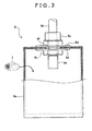
- This contact portion 6 includes a bag-shaped member 6a and a connecting port 6b and the like, as shown in FIG. 3 . Also, a granular substance 7 is filled into the contact portion 6.
- the bag-shaped member 6a may be covered as appropriate by an outer bag, not shown, or the like in order to inhibit the bag-shaped member 6a from getting cut up.
- the bag-shaped member 6a is a member that is made of nitrile butadiene rubber (NBR) that is elastic and airtight, in which a sheet of NBR is formed in a rectangular parallelepiped bag shape by appropriately vulcanize-bonding it (i.e., the sheet). Also, a hole portion 6f is formed in the bag-shaped member 6a, and the connecting port 6b that is a member for communicating the inside of the bag-shaped member 6a with the outside of the bag-shaped member 6a is arranged in the hole portion 6f.
- NBR nitrile butadiene rubber
- the connecting port 6b is attached to the hole portion 6f while ensuring that the hole portion 6f is airtight by inserting seal members 6d and fastening them by screwing on nuts 6c. Also, a vacuum duct 8b is connected to the connecting port 6b, and a filter 6e is arranged at an end portion of the connecting port 6b that is inside the bag-shaped member 6a. Also, the filter 6e is configured to prevent the granular substance 7 from coming out of the connecting port 6b.
- nitrile rubber NBR
- the material of which the bag-shaped member 6a is made is not limited to this. As long as the material is elastic and airtight, any of a variety of materials may be used according to conditions such as the operating environment and the like. Also, in this example embodiment, a case is described in which the shape of the bag-shaped member 6a is generally rectangular parallelepiped, but the shape of the bag-shaped member of the contact portion that forms the grasping apparatus of the invention is not limited to this.
- the granular substance 7 is filled inside the contact portion 6 (i.e., more specifically, the bag-shaped member 6a).
- the bag-shaped member 6a and the granular substance 7 are hardened in a suitable shape in an integrated state by reducing the pressure inside the bag-shaped member 6a such that the grains that form the granular substance 7 are held tightly together.
- the contact portion 6 preferably has properties such as 1) having good hardness when hardened, and 2) being lightweight, but the hardness of the contact portion 6 when hardened and the weight of the contact portion 6 change according to various changes in the specifications of the granular substance 7. Therefore, in the manufacturing method of the contact portion 6 according to the example embodiments of the invention, synthetic mullite that is able to be used as molding sand is used as the granular substance 7. Also, the property of the contact portion 6 can be adjusted to display the required functions of 1) and 2) above, by appropriately adjusting the grain diameter and filling volume and the like of the synthetic mullite that is used.
- the contact portion 6 (see FIGS. 2A, 2B, and 2C ) is connected to the evacuation equipment 8 by vacuum ducts 8b, while being attached to the clip portions 4b and 5b of the pawl portions 4 and 5.
- the evacuation equipment 8 is formed by means for making the contact portion 6 of the grasping apparatus 1 hard and soft, and includes a vacuum pump 8a, the vacuum ducts 8b, and an electromagnetic valve 8c and the like.
- the vacuum pump 8a is provided in the evacuation equipment 8, but a structure in which evacuating means other than the vacuum pump 8a (such as an ejector or the like) is provided is also possible.
- the means for making the contact portion hard and soft is not necessarily limited to the evacuation equipment. That is, any of various modes capable of making the contact portion hard and soft may be employed.
- the contact portion 6 becomes hard due to the grains that make up the granular substance 7 that is filled inside the bag-shaped portion 6a being held together more tightly because of increasing the volume ratio of the granular substatnce 7 to the bag-shaped portion 6a. Therefore, at this time, the contact portion 6 takes on the form in which its shape is firmly maintained.
- this contact portion 6 When this contact portion 6 is pressed, in a flexible state, against the workpiece by the clamping pressure of the pawl portions 4 and 5, the contact portion 6 is able to fit into concave portions and around convex portions on the surface of the workpiece, thus enabling the contact portion 6 to conform to the shape of the outer surface of the workpiece.
- the contact portion 6 is able to be made hard in a shape corresponding to (conforming to) the shape of the outer surface of the workpiece by activating the evacuation equipment 8 while the contact portion 6 is conformed to the shape of the outer surface of the workpiece. Therefore, a hard contact portion 6 that corresponds to the shape of the outer surface of the workpiece can be formed.
- the manufacturing method of the contact portion 6 according to the example embodiments of the invention will be described with reference to FIGS. 4 to 12 .
- the bag-shaped member 6a is manufactured using a core 10 as shown in FIG 4 .
- the core 10 is formed as a solid having a generally rectangular parallelepiped shape, in which the granular substance 7 that is an aggregate of a plurality of grains is bound together by a binder 11.
- the shape of the core 10 used in the manufacturing method of the contact portion 6 according to the example embodiments of the invention is not limited to a generally rectangular parallelepiped shape. That is, the shape of the core 10 may also be such that the corner portions are R-shaped or chamfered portions are provided, for example, corresponding to the desired shape of the bag-shaped member 6a.
- the core 10 is formed in a generally rectangular parallelepiped shape by hardening the granular substance 7 with the binder 11.
- the content volume necessary for the bag-shaped member 6a is ensured, and the amount of granular substance 7 that needs to be filled with respect to the content volume is ensured, taking the function of the contact portion 6 into account.
- the method of preparing the core 10 will be described in even greater detail.
- the first core 10A is prepared by hardening the granular substance 7 that is the member to be filled into the bag-shaped member 6a of the contact portion 6, with resin 11A as a first binder 11.
- the resin 11A is material made of phenol resin or the like that is typically used for hardening molding sand, when manufacturing a core used in molding.
- the granular substance 7 and the resin 11A are mixed together and the mixture is put into a mold 16.
- the first core 10A of the desired shape is then prepared by softening the resin 11A in this state by heating the mold 16 to bond the grains of the granular substance 7 together.
- the outer dimensions of the core 10 are able to be adjusted by forming a cavity 101 inside of it, as shown in FIG. 4B , for example.
- the content volume of the bag-shaped member 6a is able to be adjusted by adjusting the outer dimensions of the core 10.
- the ratio of the amount of granular substance 7 in the core 10 to the content volume of the bag-shaped member 6a is able to be adjusted by adjusting the content volume of the bag-shaped member 6a in this way.
- one possible method for forming this kind of cavity 101 involves preparing the core 10 with the granular substance 7 wrapped around a body having a predetermined volume made with dry ice or the like.
- the second core 10B is prepared by hardening a granular substance 7 that is a member to be filled into the bag-shaped member 6a of the contact portion 6 with liquid glass 11B as a second binder 11.
- the liquid glass 11B is a member formed from sodium silicate or the like that is typically used to harden molding sand when manufacturing a core used in molding. Then the granular substance 7 and the liquid glass 11B are mixed together and the mixture is put into the mold 16.
- the second core 10B of the desired shape is then prepared by softening the liquid glass 11B in this state by heating the mold 16 to bond the grains of the granular substance 7 together.
- the third core 10C is prepared by hardening the granular substance 7 that is a member to be filled into the bag-shaped member 6a of the contact portion 6 with mineral salt 11C as a third binder 11.
- the mineral salt 11C is a member formed from silicate of soda or the like that is typically used to harden molding sand when manufacturing a core used in molding. Then the granular substance 7 and the mineral salt 11C are mixed together and the mixture is put into the mold 16.
- the third core 10C of the desired shape is then prepared by softening the mineral salt 11C in this state by heating the mold 16 to bond the grains of the granular substance 7 together.
- the fourth core 10D is prepared by hardening the granular substance 7 that is a member to be filled into the bag-shaped member 6a of the contact portion 6 with water 11D that is a liquid as a fourth binder 11.
- the granular substance 7 and the water 11D are mixed together and the mixture is put into the mold 16.
- the fourth core 10D of the desired shape is then prepared by cooling the mold 16 in this state to solidify (i.e., freeze) the water 11D (forming ice).
- the water 11D is used as the fourth binder 11 that is a liquid.
- the liquid need only have a property that enables it to solidify (i.e., freeze) and dissolve (i.e., melt) in a predetermined temperature range.
- the liquid employed as the fourth binder 11 is not limited to the water 11D.
- a fifth core 10E is prepared by hardening the granular substance 7 that is a member to be filled into the bag-shaped member 6a of the contact portion 6 with dry ice 11E that is a solid that has a predetermined volume, and that sublimes as a fifth binder 11.
- the granular substance 7 and the dry ice 11E are mixed together and the mixture is put into the mold 16.
- the fifth core 10E of the desired shape is then prepared by hardening the granular substance 7 with the dry ice 11E, by compressing the mold 16 in this state.
- the dry ice 11E is used as the fifth binder 11 that is a solid that has a predetermined volume, and that sublimes without liquefying.
- the solid need only be able to sublime in a predetermined temperature range.
- the solid employed as the fifth binder 11 is not limited to the dry ice 11E.
- the cores 10A to 10E according to the first to the fifth example embodiments are given as examples, but the material of the core 10 used in the manufacturing method of the contact portion 6 according to the example embodiments of the invention are not limited to these. That is, as long as the material is able to harden into a solid by binding the granular substance 7, and is able to be broken up easily, other various materials may also be used.
- the bag-shaped member 6a is manufactured according to a so-called injection molding method using the cores 10A to 10E according to the example embodiments described thus far.
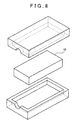
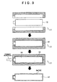
- the core 10 is arranged in a mold 17 as shown in FIGS. 8 and 9 .
- a suitable spacer or the like is interposed between the core 10 and the mold 17 to ensure a predetermined gap around the core 10 in the mold 17, as shown in FIG. 9 .
- rubber 18 that is liquid raw material is injected into the mold 17, a coating of the rubber 18 that is elastic and airtight is formed around the core 10, and this coating becomes the bag-shaped member 6a.
- the process shifts to a step of breaking up the core 10.
- the core 10 is the first core 10A or the second core 10B
- the core 10 is able to be broken up by striking the bag-shaped member 6a that is wrapped around the core 10, from the outside. Breaking up the core 10 enables the granular substance 7 that forms the core 10 to be returned to a state in which the grains flow independently again.
- the granular substance 7 can easily be placed in the state that it would have been in if it was filled into the bag-shaped member 6a by simply striking the bag-shaped member 6a.
- the contact portion 6 can easily be formed simply by forming an opening in the bag-shaped member 6a or assembling the necessary members such as the connecting port 6b to the bag-shaped member 6a.
- the core 10 when the core 10 is the third core 10C, the core 10 can be broken up by pouring water into the bag-shaped member 6a that is wrapped around the core 10. Then, the granular substance 7 that forms the core 10 can be returned to the state in which the grains are able to flow independently again, by breaking up the core 10 and drying the inside of the bag-shaped member 6a.
- the step of preparing the core 10 is performed by molding the mixture that includes the granular substance 7 and the binder 11 (i.e., the first to the third binders 11A, 11B, and 11C) into a predetermined shape by heating the mixture inside the mold 16.
- This kind of structure makes it possible to easily manufacture the core 10 that is a core for forming the bag-shaped member 6a, and that includes the granular substance 7 (i.e., the first to the third cores 10A, 10B, and 10C).
- the step of breaking up the core 10 is performed by pulverizing the cores 10A and 10B inside the bag-shaped member 6a by applying external force to the bag-shaped member 6a.
- This kind of structure makes it possible to easily break up the core 10 (i.e., the first and second cores 10A and 10B) inside the bag-shaped member 6a.
- the granular substance 7 is able to be easily granularized inside the bag-shaped member 6a.
- the step of breaking up the core 10 is performed by dissolving the mineral salt 11C that is the third binder 11 that forms the third core 10C inside the bag-shaped member 6a, by pouring water into the bag-shaped member 6a.
- This kind of structure makes it possible to easily break up the core 10 (i.e., the third core 10C) inside the bag-shaped member 6a.
- the granular substance 7 is able to be easily granularized inside the bag-shaped member 6a.
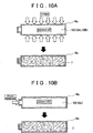
- the core 10 when the core 10 is the fourth core 10D, as shown in FIG. 11A , the core 10 is able to be broken up by heating the bag-shaped member 6a that is wrapped around the core 10, or by leaving this bag-shaped member 6a at normal temperature, for example. Also, the granular substance 7 that forms the core 10 is able to be returned to the state in which the grains are able to flow independently again, by breaking up the core 10 and drying the inside of the bag-shaped member 6a.
- the step of preparing the core 10 is performed by molding the mixture that includes the granular substance 7 and the liquid (the water 11D in this example embodiment) into a predetermined shape by solidifying (i.e., freezing) the water 11D, which is accomplished by cooling the mixture inside the mold 16.
- This kind of structure makes it possible to easily manufacture the core 10 that is a core for forming the bag-shaped member 6a, and that includes the granular substance 7 (i.e., the fourth core 10D).
- the step of breaking up the core 10 is performed by dissolving (i.e., melting) a solidified (i.e., frozen) liquid that is the fourth binder 11 that forms the fourth core 10D inside the bag-shaped member 6a (the frozen water 11D (i.e., ice) in this example embodiment), by heating the bag-shaped member 6a or leaving the bag-shaped member 6a.
- a solidified (i.e., frozen) liquid that is the fourth binder 11 that forms the fourth core 10D inside the bag-shaped member 6a (the frozen water 11D (i.e., ice) in this example embodiment)
- the granular substance 7 is able to be easily granularized inside the bag-shaped member 6a.
- the core 10 is the fifth core 10E, as shown in FIG. 11B , for example, the core 10 is able to be broken up by heating the bag-shaped member 6a that is wrapped around the core 10, or by leaving this bag-shaped member 6a at normal temperature, for example. Also, the granular substance 7 that forms the core 10 is able to be returned to the state in which the grains are able to flow independently again, by breaking up the core 10.
- the step of preparing the core 10 is performed by molding the mixture that includes the granular substance 7 and the solid (the dry ice 11E in this example embodiment) that has a predetermined volume, and that sublimes without liquefying as the binder 11 into a predetermined shape, which is accomplished by compressing this mixture inside the mold 16.
- This kind of structure makes it possible to easily manufacture the core 10 that is a core for forming the bag-shaped member 6a, and that includes the granular substance 7 (i.e., the fifth core 10E).
- the step of breaking up the core 10 is performed by subliming a solid (the dry ice 11E in this example embodiment) having a predetermined volume as the binder 11 that forms the core 10 inside the bag-shaped member 6a, which is accomplished by heating the bag-shaped member 6a or leaving the bag-shaped member 6a.
- This kind of structure makes it possible to easily break up the core 10 (i.e., the fifth core 10E) inside the bag-shaped member 6a.
- the granular substance 7 is able to be easily granularized inside the bag-shaped member 6a.
- the manufacturing method of the contact portion 6 according to another example embodiment of the invention will be described.
- the bag-shaped member 6a is manufactured by a so-called dip (dunk) molding method using the cores 10A to 10E according to the example embodiments described thus far.
- a so-called dip (dunk) molding method using the cores 10A to 10E according to the example embodiments described thus far.
- FIG. 12 when the core 10 that is the core is dipped into the rubber 18 that is the liquid raw material, a covering made of the rubber 18 that is elastic and airtight is able to be formed around the core 10, and this covering becomes the bag-shaped member 6a.
- the process shifts to a step of breaking of the core 10.
- the same step as the step in the manufacturing method of the contact portion 6 according to the previous example embodiment of the invention may be employed.
- the core 10 that is a structure that includes the granular substance 7 is prepared by a method such as that described above, and then the bag-shaped member 6a is manufactured using the prepared core 10 as the core.
- the granular substance 7 is easily granularized in the bag-shaped member 6a by breaking up the core 10 inside the bag-shaped member 6a.
- the manufacturing method of a contact portion is a manufacturing method of the contact portion 6 that includes the rubber bag-shaped member 6a that is made of material (rubber 18 in this example embodiment) that is elastic and airtight, and the granular substance 7 that is filled inside of the bag-shaped member 6a, and that is a member for forming a portion of the grasping apparatus 1 that contacts a workpiece.
- This manufacturing method includes a step of preparing the core 10 that is a core for forming the bag-shaped member 6a, by hardening the granular substance 7 with the binder 11, a step of forming the bag-shaped member 6a by forming a covering made of the rubber 18 that is material that is elastic and airtight around the core 10, and a step of breaking up the core 10 inside the bag-shaped member 6a.
- This kind of structure makes it easy to manufacture the contact portion 6 without providing another step for filling the granular substance 7 into the bag-shaped member 6a.
- the manufacturing method of the bag-shaped member 6a is not limited to the manufacturing methods of the contact portion 6 according to these example embodiments of the invention. That is, any of a variety of manufacturing methods of the bag-shaped member 6a may be employed as long as the method is one that enables a covering made of material that is elastic and airtight (such as the rubber 18 or synthetic resin, for example) to be formed around the core 10.
Landscapes
- Engineering & Computer Science (AREA)
- Mechanical Engineering (AREA)
- Manufacturing & Machinery (AREA)
- Robotics (AREA)
- Moulds For Moulding Plastics Or The Like (AREA)
- Making Paper Articles (AREA)
- Containers And Plastic Fillers For Packaging (AREA)
- Bag Frames (AREA)
- Molds, Cores, And Manufacturing Methods Thereof (AREA)
Priority Applications (1)
| Application Number | Priority Date | Filing Date | Title |
|---|---|---|---|
| PL13705006T PL2804748T3 (pl) | 2012-01-16 | 2013-01-14 | Sposób wytwarzania korpusu workowego z granulowanym wypełnieniem |
Applications Claiming Priority (2)
| Application Number | Priority Date | Filing Date | Title |
|---|---|---|---|
| JP2012005972A JP5765248B2 (ja) | 2012-01-16 | 2012-01-16 | 当接部の製造方法 |
| PCT/IB2013/000042 WO2013108106A2 (en) | 2012-01-16 | 2013-01-14 | Manufacturing method of bag body |
Publications (2)
| Publication Number | Publication Date |
|---|---|
| EP2804748A2 EP2804748A2 (en) | 2014-11-26 |
| EP2804748B1 true EP2804748B1 (en) | 2015-07-01 |
Family
ID=47739407
Family Applications (1)
| Application Number | Title | Priority Date | Filing Date |
|---|---|---|---|
| EP13705006.8A Not-in-force EP2804748B1 (en) | 2012-01-16 | 2013-01-14 | Manufacturing method of bag body with a granular filling |
Country Status (8)
| Country | Link |
|---|---|
| US (1) | US9409317B2 (pl) |
| EP (1) | EP2804748B1 (pl) |
| JP (1) | JP5765248B2 (pl) |
| CN (1) | CN104039538B (pl) |
| BR (1) | BR112014016985B1 (pl) |
| IN (1) | IN2014DN05858A (pl) |
| PL (1) | PL2804748T3 (pl) |
| WO (1) | WO2013108106A2 (pl) |
Families Citing this family (12)
| Publication number | Priority date | Publication date | Assignee | Title |
|---|---|---|---|---|
| CN106426188B (zh) * | 2016-12-24 | 2018-10-30 | 江苏山扬智能装备有限公司 | 一种程控工业机器人 |
| CN106426187B (zh) * | 2016-12-24 | 2019-04-19 | 聊城鑫泰机床有限公司 | 工业机器人控制方法 |
| JP6588935B2 (ja) * | 2017-03-13 | 2019-10-09 | 株式会社東芝 | 把持ツール、把持システム、および把持性能の評価方法 |
| JP7006404B2 (ja) * | 2018-03-15 | 2022-01-24 | トヨタ自動車株式会社 | ワークの支持装置、支持方法及びロボットアーム |
| WO2019222797A1 (en) | 2018-05-21 | 2019-11-28 | The University Of Sydney | A method of fabricating a casting |
| KR102114290B1 (ko) * | 2018-05-25 | 2020-05-22 | 정덕채 | 고무백 및 고무백 제조 방법 |
| CN111059107B (zh) * | 2018-10-17 | 2024-10-22 | 杨斌堂 | 自适应夹持摆动体 |
| CN111204006A (zh) * | 2020-01-16 | 2020-05-29 | 大成普道新材料技术有限公司 | 一种中空聚双环戊二烯制品的生产方法及应用 |
| CN111673957A (zh) * | 2020-07-11 | 2020-09-18 | 厦门新旺新材料科技有限公司 | 一种中空复材构造件成型辅助充气气模 |
| DE102021105844A1 (de) * | 2021-03-10 | 2022-09-15 | Fit Ag | Verfahren zur Herstellung eines elastisch verformbaren Formteils |
| CN117245829A (zh) * | 2022-07-11 | 2023-12-19 | 郑州大学第一附属医院 | 一种可根据个人手掌大小制造乳胶手套的自动佩戴装置 |
| CN116901124A (zh) * | 2023-08-21 | 2023-10-20 | 广东电网有限责任公司 | 一种仪表检定夹爪及其使用方法 |
Citations (1)
| Publication number | Priority date | Publication date | Assignee | Title |
|---|---|---|---|---|
| WO2011135450A1 (en) * | 2010-04-28 | 2011-11-03 | Toyota Jidosha Kabushiki Kaisha | Grasping apparatus having bag members filled by a granular substance |
Family Cites Families (15)
| Publication number | Priority date | Publication date | Assignee | Title |
|---|---|---|---|---|
| FR588657A (fr) * | 1924-11-07 | 1925-05-13 | Goodyear Tire & Rubber | Noyau pour pièces creuses en caoutchouc et sa méthode d'établissement |
| GB621046A (en) * | 1946-03-12 | 1949-04-04 | Dunlop Rubber Co | Improvements in or relating to compositions for games ball cores and to the production of games balls therefrom |
| JPS5820430A (ja) * | 1981-07-28 | 1983-02-05 | Dainichi Nippon Cables Ltd | 狭口容器の製造方法 |
| US4424183A (en) * | 1982-07-06 | 1984-01-03 | Baker International Corporation | Destructible core structure and method for using same |
| JPH062352B2 (ja) * | 1985-05-07 | 1994-01-12 | 旭有機材工業株式会社 | 硬化性プラスチックスの成型方法 |
| JPS62117707A (ja) * | 1985-11-18 | 1987-05-29 | Takagi Kogyo Kk | プラスチツク製品の成形法 |
| JPS6482910A (en) * | 1987-09-26 | 1989-03-28 | Idemitsu Petrochemical Co | Molding method of molded product having hollow part |
| FI922716A7 (fi) * | 1992-06-11 | 1993-12-12 | Harri Sahari | Menetelmä muovikappaleiden valmistuksessa |
| US5516477A (en) * | 1994-08-01 | 1996-05-14 | Ford Motor Company | Resin molding process utilizing a glass core |
| JPH09123082A (ja) * | 1995-11-01 | 1997-05-13 | Kao Corp | 物品把持装置 |
| JPH11123723A (ja) * | 1997-10-23 | 1999-05-11 | Yokohama Rubber Co Ltd:The | ゴム製容器の製造方法 |
| JP3839004B2 (ja) | 2003-08-06 | 2006-11-01 | バンドー化学株式会社 | ゴム製袋体とその製造方法 |
| JP2008273604A (ja) | 2007-05-02 | 2008-11-13 | Newlong Industrial Co | 熱溶着性合成樹脂袋への粉粒体充填封緘方法 |
| DE112011101331T5 (de) * | 2010-04-15 | 2013-01-31 | Cornell University | Greif- und Ablegevorrichtung und -verfahren |
| US20120292811A1 (en) * | 2010-07-01 | 2012-11-22 | Crosseffect, Inc. | Method for producing resin-molded body of hollow structure and a core used in it |
-
2012
- 2012-01-16 JP JP2012005972A patent/JP5765248B2/ja not_active Expired - Fee Related
-
2013
- 2013-01-14 PL PL13705006T patent/PL2804748T3/pl unknown
- 2013-01-14 WO PCT/IB2013/000042 patent/WO2013108106A2/en not_active Ceased
- 2013-01-14 BR BR112014016985-3A patent/BR112014016985B1/pt not_active IP Right Cessation
- 2013-01-14 CN CN201380005680.XA patent/CN104039538B/zh not_active Expired - Fee Related
- 2013-01-14 US US14/372,303 patent/US9409317B2/en not_active Expired - Fee Related
- 2013-01-14 EP EP13705006.8A patent/EP2804748B1/en not_active Not-in-force
-
2014
- 2014-07-14 IN IN5858DEN2014 patent/IN2014DN05858A/en unknown
Patent Citations (1)
| Publication number | Priority date | Publication date | Assignee | Title |
|---|---|---|---|---|
| WO2011135450A1 (en) * | 2010-04-28 | 2011-11-03 | Toyota Jidosha Kabushiki Kaisha | Grasping apparatus having bag members filled by a granular substance |
Also Published As
| Publication number | Publication date |
|---|---|
| CN104039538A (zh) | 2014-09-10 |
| US9409317B2 (en) | 2016-08-09 |
| WO2013108106A3 (en) | 2013-10-31 |
| JP2013144403A (ja) | 2013-07-25 |
| JP5765248B2 (ja) | 2015-08-19 |
| CN104039538B (zh) | 2016-08-17 |
| BR112014016985A2 (pt) | 2017-06-13 |
| US20140374942A1 (en) | 2014-12-25 |
| BR112014016985A8 (pt) | 2017-07-04 |
| BR112014016985B1 (pt) | 2020-11-24 |
| EP2804748A2 (en) | 2014-11-26 |
| WO2013108106A2 (en) | 2013-07-25 |
| PL2804748T3 (pl) | 2015-12-31 |
| IN2014DN05858A (pl) | 2015-05-22 |
Similar Documents
| Publication | Publication Date | Title |
|---|---|---|
| EP2804748B1 (en) | Manufacturing method of bag body with a granular filling | |
| US9599175B2 (en) | Caliper for disc brakes | |
| WO2008141218A3 (en) | Composite component and method of manufacturing the same | |
| KR20140108634A (ko) | 중공부를 갖는 열가소성 수지 성형체 및 그의 제조 방법 | |
| JP5969326B2 (ja) | 断熱金型 | |
| WO2009063985A1 (ja) | 現像ブレード用金型及び現像ブレードの製造方法 | |
| WO2007019832A3 (de) | Verfahren und vorrichtung zum pressen eines formteils mit einem querstempel | |
| WO2010007142A3 (de) | Giessvorrichtung und giessverfahren zur herstellung hohler gegenstände mit einem beim giessvorgang gebildeten projektil | |
| WO2008085820A8 (en) | Method of reinforcing low melting temperature cast metal parts | |
| JP2013244621A (ja) | レドームの製造方法及びレドーム | |
| CN202088366U (zh) | 浇注型聚氨酯输料管内管的成型模具 | |
| JP5851379B2 (ja) | 射出圧縮成形用金型 | |
| KR101067015B1 (ko) | 다이캐스팅 금형 | |
| TW200626333A (en) | Resin casting mold and method of casting resin | |
| CN203485445U (zh) | 压合装置以及3d打印机 | |
| JP4124113B2 (ja) | インサート成形方法 | |
| WO2014004571A3 (en) | Downhole tool with composite slip system | |
| CN103747934A (zh) | 复合平衡杆制造装置 | |
| CN210450972U (zh) | 一种齿轮成型模具 | |
| CN104929941A (zh) | 一种汽车真空泵滑片及其制作工艺 | |
| Yan et al. | Microstructure and properties of vacuum counter-pressure cast aluminum alloy. | |
| WO2012004654A8 (en) | Method for the production of an element subject to wear, element subject to wear and temporary aggregation structure to produce said element subject to wear | |
| Dai et al. | New method of injection and compression molding. | |
| CN204182863U (zh) | 带销孔的安全卡射蜡模具 | |
| Powell | An advanced breaker core system with enhanced knock off properties for high pressure moulding applications |
Legal Events
| Date | Code | Title | Description |
|---|---|---|---|
| PUAI | Public reference made under article 153(3) epc to a published international application that has entered the european phase |
Free format text: ORIGINAL CODE: 0009012 |
|
| 17P | Request for examination filed |
Effective date: 20140716 |
|
| AK | Designated contracting states |
Kind code of ref document: A2 Designated state(s): AL AT BE BG CH CY CZ DE DK EE ES FI FR GB GR HR HU IE IS IT LI LT LU LV MC MK MT NL NO PL PT RO RS SE SI SK SM TR |
|
| GRAP | Despatch of communication of intention to grant a patent |
Free format text: ORIGINAL CODE: EPIDOSNIGR1 |
|
| INTG | Intention to grant announced |
Effective date: 20150113 |
|
| RIC1 | Information provided on ipc code assigned before grant |
Ipc: B29C 41/14 20060101ALN20141222BHEP Ipc: B29C 45/44 20060101ALI20141222BHEP Ipc: B29K 95/00 20060101ALN20141222BHEP Ipc: B29D 22/00 20060101AFI20141222BHEP Ipc: B29K 21/00 20060101ALN20141222BHEP Ipc: B25J 15/00 20060101ALI20141222BHEP |
|
| DAX | Request for extension of the european patent (deleted) | ||
| GRAS | Grant fee paid |
Free format text: ORIGINAL CODE: EPIDOSNIGR3 |
|
| GRAA | (expected) grant |
Free format text: ORIGINAL CODE: 0009210 |
|
| AK | Designated contracting states |
Kind code of ref document: B1 Designated state(s): AL AT BE BG CH CY CZ DE DK EE ES FI FR GB GR HR HU IE IS IT LI LT LU LV MC MK MT NL NO PL PT RO RS SE SI SK SM TR |
|
| REG | Reference to a national code |
Ref country code: GB Ref legal event code: FG4D |
|
| REG | Reference to a national code |
Ref country code: AT Ref legal event code: REF Ref document number: 733695 Country of ref document: AT Kind code of ref document: T Effective date: 20150715 Ref country code: CH Ref legal event code: EP |
|
| REG | Reference to a national code |
Ref country code: IE Ref legal event code: FG4D |
|
| REG | Reference to a national code |
Ref country code: DE Ref legal event code: R096 Ref document number: 602013002143 Country of ref document: DE |
|
| REG | Reference to a national code |
Ref country code: DE Ref legal event code: R084 Ref document number: 602013002143 Country of ref document: DE |
|
| REG | Reference to a national code |
Ref country code: AT Ref legal event code: MK05 Ref document number: 733695 Country of ref document: AT Kind code of ref document: T Effective date: 20150701 |
|
| REG | Reference to a national code |
Ref country code: GB Ref legal event code: 746 Effective date: 20151111 |
|
| REG | Reference to a national code |
Ref country code: FR Ref legal event code: PLFP Year of fee payment: 4 |
|
| REG | Reference to a national code |
Ref country code: NL Ref legal event code: MP Effective date: 20150701 |
|
| REG | Reference to a national code |
Ref country code: LT Ref legal event code: MG4D |
|
| REG | Reference to a national code |
Ref country code: PL Ref legal event code: T3 |
|
| PG25 | Lapsed in a contracting state [announced via postgrant information from national office to epo] |
Ref country code: FI Free format text: LAPSE BECAUSE OF FAILURE TO SUBMIT A TRANSLATION OF THE DESCRIPTION OR TO PAY THE FEE WITHIN THE PRESCRIBED TIME-LIMIT Effective date: 20150701 Ref country code: NO Free format text: LAPSE BECAUSE OF FAILURE TO SUBMIT A TRANSLATION OF THE DESCRIPTION OR TO PAY THE FEE WITHIN THE PRESCRIBED TIME-LIMIT Effective date: 20151001 Ref country code: GR Free format text: LAPSE BECAUSE OF FAILURE TO SUBMIT A TRANSLATION OF THE DESCRIPTION OR TO PAY THE FEE WITHIN THE PRESCRIBED TIME-LIMIT Effective date: 20151002 Ref country code: LV Free format text: LAPSE BECAUSE OF FAILURE TO SUBMIT A TRANSLATION OF THE DESCRIPTION OR TO PAY THE FEE WITHIN THE PRESCRIBED TIME-LIMIT Effective date: 20150701 Ref country code: LT Free format text: LAPSE BECAUSE OF FAILURE TO SUBMIT A TRANSLATION OF THE DESCRIPTION OR TO PAY THE FEE WITHIN THE PRESCRIBED TIME-LIMIT Effective date: 20150701 |
|
| PG25 | Lapsed in a contracting state [announced via postgrant information from national office to epo] |
Ref country code: SE Free format text: LAPSE BECAUSE OF FAILURE TO SUBMIT A TRANSLATION OF THE DESCRIPTION OR TO PAY THE FEE WITHIN THE PRESCRIBED TIME-LIMIT Effective date: 20150701 Ref country code: HR Free format text: LAPSE BECAUSE OF FAILURE TO SUBMIT A TRANSLATION OF THE DESCRIPTION OR TO PAY THE FEE WITHIN THE PRESCRIBED TIME-LIMIT Effective date: 20150701 Ref country code: ES Free format text: LAPSE BECAUSE OF FAILURE TO SUBMIT A TRANSLATION OF THE DESCRIPTION OR TO PAY THE FEE WITHIN THE PRESCRIBED TIME-LIMIT Effective date: 20150701 Ref country code: RS Free format text: LAPSE BECAUSE OF FAILURE TO SUBMIT A TRANSLATION OF THE DESCRIPTION OR TO PAY THE FEE WITHIN THE PRESCRIBED TIME-LIMIT Effective date: 20150701 Ref country code: IS Free format text: LAPSE BECAUSE OF FAILURE TO SUBMIT A TRANSLATION OF THE DESCRIPTION OR TO PAY THE FEE WITHIN THE PRESCRIBED TIME-LIMIT Effective date: 20151101 Ref country code: AT Free format text: LAPSE BECAUSE OF FAILURE TO SUBMIT A TRANSLATION OF THE DESCRIPTION OR TO PAY THE FEE WITHIN THE PRESCRIBED TIME-LIMIT Effective date: 20150701 Ref country code: PT Free format text: LAPSE BECAUSE OF FAILURE TO SUBMIT A TRANSLATION OF THE DESCRIPTION OR TO PAY THE FEE WITHIN THE PRESCRIBED TIME-LIMIT Effective date: 20151102 |
|
| REG | Reference to a national code |
Ref country code: DE Ref legal event code: R097 Ref document number: 602013002143 Country of ref document: DE |
|
| PG25 | Lapsed in a contracting state [announced via postgrant information from national office to epo] |
Ref country code: DK Free format text: LAPSE BECAUSE OF FAILURE TO SUBMIT A TRANSLATION OF THE DESCRIPTION OR TO PAY THE FEE WITHIN THE PRESCRIBED TIME-LIMIT Effective date: 20150701 Ref country code: EE Free format text: LAPSE BECAUSE OF FAILURE TO SUBMIT A TRANSLATION OF THE DESCRIPTION OR TO PAY THE FEE WITHIN THE PRESCRIBED TIME-LIMIT Effective date: 20150701 Ref country code: CZ Free format text: LAPSE BECAUSE OF FAILURE TO SUBMIT A TRANSLATION OF THE DESCRIPTION OR TO PAY THE FEE WITHIN THE PRESCRIBED TIME-LIMIT Effective date: 20150701 Ref country code: SK Free format text: LAPSE BECAUSE OF FAILURE TO SUBMIT A TRANSLATION OF THE DESCRIPTION OR TO PAY THE FEE WITHIN THE PRESCRIBED TIME-LIMIT Effective date: 20150701 Ref country code: IT Free format text: LAPSE BECAUSE OF FAILURE TO SUBMIT A TRANSLATION OF THE DESCRIPTION OR TO PAY THE FEE WITHIN THE PRESCRIBED TIME-LIMIT Effective date: 20150701 |
|
| PLBE | No opposition filed within time limit |
Free format text: ORIGINAL CODE: 0009261 |
|
| STAA | Information on the status of an ep patent application or granted ep patent |
Free format text: STATUS: NO OPPOSITION FILED WITHIN TIME LIMIT |
|
| PG25 | Lapsed in a contracting state [announced via postgrant information from national office to epo] |
Ref country code: RO Free format text: LAPSE BECAUSE OF FAILURE TO SUBMIT A TRANSLATION OF THE DESCRIPTION OR TO PAY THE FEE WITHIN THE PRESCRIBED TIME-LIMIT Effective date: 20150701 Ref country code: BE Free format text: LAPSE BECAUSE OF NON-PAYMENT OF DUE FEES Effective date: 20160131 |
|
| 26N | No opposition filed |
Effective date: 20160404 |
|
| PG25 | Lapsed in a contracting state [announced via postgrant information from national office to epo] |
Ref country code: SI Free format text: LAPSE BECAUSE OF FAILURE TO SUBMIT A TRANSLATION OF THE DESCRIPTION OR TO PAY THE FEE WITHIN THE PRESCRIBED TIME-LIMIT Effective date: 20150701 Ref country code: LU Free format text: LAPSE BECAUSE OF FAILURE TO SUBMIT A TRANSLATION OF THE DESCRIPTION OR TO PAY THE FEE WITHIN THE PRESCRIBED TIME-LIMIT Effective date: 20160114 |
|
| REG | Reference to a national code |
Ref country code: CH Ref legal event code: PL |
|
| PG25 | Lapsed in a contracting state [announced via postgrant information from national office to epo] |
Ref country code: MC Free format text: LAPSE BECAUSE OF FAILURE TO SUBMIT A TRANSLATION OF THE DESCRIPTION OR TO PAY THE FEE WITHIN THE PRESCRIBED TIME-LIMIT Effective date: 20150701 |
|
| PG25 | Lapsed in a contracting state [announced via postgrant information from national office to epo] |
Ref country code: LI Free format text: LAPSE BECAUSE OF NON-PAYMENT OF DUE FEES Effective date: 20160131 Ref country code: CH Free format text: LAPSE BECAUSE OF NON-PAYMENT OF DUE FEES Effective date: 20160131 |
|
| REG | Reference to a national code |
Ref country code: IE Ref legal event code: MM4A |
|
| REG | Reference to a national code |
Ref country code: FR Ref legal event code: PLFP Year of fee payment: 5 |
|
| PG25 | Lapsed in a contracting state [announced via postgrant information from national office to epo] |
Ref country code: BE Free format text: LAPSE BECAUSE OF FAILURE TO SUBMIT A TRANSLATION OF THE DESCRIPTION OR TO PAY THE FEE WITHIN THE PRESCRIBED TIME-LIMIT Effective date: 20150701 |
|
| PG25 | Lapsed in a contracting state [announced via postgrant information from national office to epo] |
Ref country code: IE Free format text: LAPSE BECAUSE OF NON-PAYMENT OF DUE FEES Effective date: 20160114 |
|
| PG25 | Lapsed in a contracting state [announced via postgrant information from national office to epo] |
Ref country code: NL Free format text: LAPSE BECAUSE OF FAILURE TO SUBMIT A TRANSLATION OF THE DESCRIPTION OR TO PAY THE FEE WITHIN THE PRESCRIBED TIME-LIMIT Effective date: 20150701 |
|
| PG25 | Lapsed in a contracting state [announced via postgrant information from national office to epo] |
Ref country code: MT Free format text: LAPSE BECAUSE OF FAILURE TO SUBMIT A TRANSLATION OF THE DESCRIPTION OR TO PAY THE FEE WITHIN THE PRESCRIBED TIME-LIMIT Effective date: 20150701 |
|
| REG | Reference to a national code |
Ref country code: FR Ref legal event code: PLFP Year of fee payment: 6 |
|
| PG25 | Lapsed in a contracting state [announced via postgrant information from national office to epo] |
Ref country code: SM Free format text: LAPSE BECAUSE OF FAILURE TO SUBMIT A TRANSLATION OF THE DESCRIPTION OR TO PAY THE FEE WITHIN THE PRESCRIBED TIME-LIMIT Effective date: 20150701 Ref country code: HU Free format text: LAPSE BECAUSE OF FAILURE TO SUBMIT A TRANSLATION OF THE DESCRIPTION OR TO PAY THE FEE WITHIN THE PRESCRIBED TIME-LIMIT; INVALID AB INITIO Effective date: 20130114 |
|
| PG25 | Lapsed in a contracting state [announced via postgrant information from national office to epo] |
Ref country code: MK Free format text: LAPSE BECAUSE OF FAILURE TO SUBMIT A TRANSLATION OF THE DESCRIPTION OR TO PAY THE FEE WITHIN THE PRESCRIBED TIME-LIMIT Effective date: 20150701 Ref country code: CY Free format text: LAPSE BECAUSE OF FAILURE TO SUBMIT A TRANSLATION OF THE DESCRIPTION OR TO PAY THE FEE WITHIN THE PRESCRIBED TIME-LIMIT Effective date: 20150701 Ref country code: MT Free format text: LAPSE BECAUSE OF FAILURE TO SUBMIT A TRANSLATION OF THE DESCRIPTION OR TO PAY THE FEE WITHIN THE PRESCRIBED TIME-LIMIT Effective date: 20160131 |
|
| PG25 | Lapsed in a contracting state [announced via postgrant information from national office to epo] |
Ref country code: BG Free format text: LAPSE BECAUSE OF FAILURE TO SUBMIT A TRANSLATION OF THE DESCRIPTION OR TO PAY THE FEE WITHIN THE PRESCRIBED TIME-LIMIT Effective date: 20150701 |
|
| PG25 | Lapsed in a contracting state [announced via postgrant information from national office to epo] |
Ref country code: TR Free format text: LAPSE BECAUSE OF FAILURE TO SUBMIT A TRANSLATION OF THE DESCRIPTION OR TO PAY THE FEE WITHIN THE PRESCRIBED TIME-LIMIT Effective date: 20150701 Ref country code: AL Free format text: LAPSE BECAUSE OF FAILURE TO SUBMIT A TRANSLATION OF THE DESCRIPTION OR TO PAY THE FEE WITHIN THE PRESCRIBED TIME-LIMIT Effective date: 20150701 |
|
| PGFP | Annual fee paid to national office [announced via postgrant information from national office to epo] |
Ref country code: GB Payment date: 20211206 Year of fee payment: 10 Ref country code: FR Payment date: 20211217 Year of fee payment: 10 |
|
| PGFP | Annual fee paid to national office [announced via postgrant information from national office to epo] |
Ref country code: PL Payment date: 20211214 Year of fee payment: 10 |
|
| PGFP | Annual fee paid to national office [announced via postgrant information from national office to epo] |
Ref country code: DE Payment date: 20211130 Year of fee payment: 10 |
|
| REG | Reference to a national code |
Ref country code: DE Ref legal event code: R119 Ref document number: 602013002143 Country of ref document: DE |
|
| GBPC | Gb: european patent ceased through non-payment of renewal fee |
Effective date: 20230114 |
|
| PG25 | Lapsed in a contracting state [announced via postgrant information from national office to epo] |
Ref country code: GB Free format text: LAPSE BECAUSE OF NON-PAYMENT OF DUE FEES Effective date: 20230114 Ref country code: DE Free format text: LAPSE BECAUSE OF NON-PAYMENT OF DUE FEES Effective date: 20230801 |
|
| PG25 | Lapsed in a contracting state [announced via postgrant information from national office to epo] |
Ref country code: FR Free format text: LAPSE BECAUSE OF NON-PAYMENT OF DUE FEES Effective date: 20230131 |
|
| PG25 | Lapsed in a contracting state [announced via postgrant information from national office to epo] |
Ref country code: PL Free format text: LAPSE BECAUSE OF NON-PAYMENT OF DUE FEES Effective date: 20230114 |