EP2803108B1 - Lithium all-solid-state battery - Google Patents
Lithium all-solid-state battery Download PDFInfo
- Publication number
- EP2803108B1 EP2803108B1 EP13757981.9A EP13757981A EP2803108B1 EP 2803108 B1 EP2803108 B1 EP 2803108B1 EP 13757981 A EP13757981 A EP 13757981A EP 2803108 B1 EP2803108 B1 EP 2803108B1
- Authority
- EP
- European Patent Office
- Prior art keywords
- fes
- solid
- capacity
- cell
- electrolyte
- Prior art date
- Legal status (The legal status is an assumption and is not a legal conclusion. Google has not performed a legal analysis and makes no representation as to the accuracy of the status listed.)
- Active
Links
- 229910052744 lithium Inorganic materials 0.000 title claims description 29
- WHXSMMKQMYFTQS-UHFFFAOYSA-N Lithium Chemical compound [Li] WHXSMMKQMYFTQS-UHFFFAOYSA-N 0.000 title claims description 18
- 239000003792 electrolyte Substances 0.000 claims description 52
- NINIDFKCEFEMDL-UHFFFAOYSA-N Sulfur Chemical compound [S] NINIDFKCEFEMDL-UHFFFAOYSA-N 0.000 claims description 28
- 239000002245 particle Substances 0.000 claims description 20
- 239000007787 solid Substances 0.000 claims description 19
- OKTJSMMVPCPJKN-UHFFFAOYSA-N Carbon Chemical compound [C] OKTJSMMVPCPJKN-UHFFFAOYSA-N 0.000 claims description 14
- MBMLMWLHJBBADN-UHFFFAOYSA-N Ferrous sulfide Chemical compound [Fe]=S MBMLMWLHJBBADN-UHFFFAOYSA-N 0.000 claims description 4
- 239000000654 additive Substances 0.000 claims description 2
- 230000000996 additive effect Effects 0.000 claims description 2
- 229910002804 graphite Inorganic materials 0.000 claims description 2
- 239000002391 graphite-based active material Substances 0.000 claims 1
- 239000002409 silicon-based active material Substances 0.000 claims 1
- 229910052683 pyrite Inorganic materials 0.000 description 114
- 229910052960 marcasite Inorganic materials 0.000 description 111
- NIFIFKQPDTWWGU-UHFFFAOYSA-N pyrite Chemical compound [Fe+2].[S-][S-] NIFIFKQPDTWWGU-UHFFFAOYSA-N 0.000 description 80
- 229910001216 Li2S Inorganic materials 0.000 description 60
- 239000002131 composite material Substances 0.000 description 42
- 238000006243 chemical reaction Methods 0.000 description 31
- XEEYBQQBJWHFJM-UHFFFAOYSA-N iron Substances [Fe] XEEYBQQBJWHFJM-UHFFFAOYSA-N 0.000 description 31
- 239000011521 glass Substances 0.000 description 28
- 239000007784 solid electrolyte Substances 0.000 description 26
- 238000002441 X-ray diffraction Methods 0.000 description 22
- 230000015572 biosynthetic process Effects 0.000 description 22
- 229910052717 sulfur Inorganic materials 0.000 description 19
- 238000001994 activation Methods 0.000 description 18
- 229910001416 lithium ion Inorganic materials 0.000 description 18
- 239000000463 material Substances 0.000 description 18
- 238000006722 reduction reaction Methods 0.000 description 18
- 239000011593 sulfur Substances 0.000 description 18
- 230000004913 activation Effects 0.000 description 17
- 230000009467 reduction Effects 0.000 description 17
- 239000011149 active material Substances 0.000 description 16
- 230000001351 cycling effect Effects 0.000 description 15
- 229910003092 TiS2 Inorganic materials 0.000 description 14
- 239000006230 acetylene black Substances 0.000 description 13
- 229910012761 LiTiS2 Inorganic materials 0.000 description 12
- 239000007788 liquid Substances 0.000 description 12
- 238000000034 method Methods 0.000 description 12
- 239000000203 mixture Substances 0.000 description 12
- 239000000047 product Substances 0.000 description 12
- 238000003801 milling Methods 0.000 description 11
- VYPSYNLAJGMNEJ-UHFFFAOYSA-N Silicium dioxide Chemical compound O=[Si]=O VYPSYNLAJGMNEJ-UHFFFAOYSA-N 0.000 description 10
- 238000004458 analytical method Methods 0.000 description 10
- 230000002441 reversible effect Effects 0.000 description 10
- UCKMPCXJQFINFW-UHFFFAOYSA-N Sulphide Chemical compound [S-2] UCKMPCXJQFINFW-UHFFFAOYSA-N 0.000 description 9
- 229910052742 iron Inorganic materials 0.000 description 9
- 229910052751 metal Inorganic materials 0.000 description 9
- 239000002184 metal Substances 0.000 description 9
- 239000002105 nanoparticle Substances 0.000 description 9
- 239000005077 polysulfide Substances 0.000 description 9
- 229920001021 polysulfide Polymers 0.000 description 9
- 150000008117 polysulfides Polymers 0.000 description 9
- 239000002243 precursor Substances 0.000 description 9
- 238000012360 testing method Methods 0.000 description 9
- 239000000843 powder Substances 0.000 description 8
- 229910052952 pyrrhotite Inorganic materials 0.000 description 8
- 230000002829 reductive effect Effects 0.000 description 8
- 229910017108 Fe—Fe Inorganic materials 0.000 description 7
- 238000000349 field-emission scanning electron micrograph Methods 0.000 description 7
- 239000002241 glass-ceramic Substances 0.000 description 7
- 230000003647 oxidation Effects 0.000 description 7
- 238000007254 oxidation reaction Methods 0.000 description 7
- 238000003786 synthesis reaction Methods 0.000 description 7
- XKRFYHLGVUSROY-UHFFFAOYSA-N Argon Chemical compound [Ar] XKRFYHLGVUSROY-UHFFFAOYSA-N 0.000 description 6
- LYCAIKOWRPUZTN-UHFFFAOYSA-N Ethylene glycol Chemical compound OCCO LYCAIKOWRPUZTN-UHFFFAOYSA-N 0.000 description 6
- 229910004600 P2S5 Inorganic materials 0.000 description 6
- HEMHJVSKTPXQMS-UHFFFAOYSA-M Sodium hydroxide Chemical compound [OH-].[Na+] HEMHJVSKTPXQMS-UHFFFAOYSA-M 0.000 description 6
- 238000005054 agglomeration Methods 0.000 description 6
- 230000002776 aggregation Effects 0.000 description 6
- 230000000875 corresponding effect Effects 0.000 description 6
- 230000002950 deficient Effects 0.000 description 6
- 238000002173 high-resolution transmission electron microscopy Methods 0.000 description 6
- 238000011065 in-situ storage Methods 0.000 description 6
- 238000005259 measurement Methods 0.000 description 6
- 239000011028 pyrite Substances 0.000 description 6
- 229910052723 transition metal Inorganic materials 0.000 description 6
- -1 transition metal sulfide Chemical class 0.000 description 6
- LFQSCWFLJHTTHZ-UHFFFAOYSA-N Ethanol Chemical compound CCO LFQSCWFLJHTTHZ-UHFFFAOYSA-N 0.000 description 5
- 230000000694 effects Effects 0.000 description 5
- 230000014759 maintenance of location Effects 0.000 description 5
- 238000003701 mechanical milling Methods 0.000 description 5
- 239000002114 nanocomposite Substances 0.000 description 5
- 230000008569 process Effects 0.000 description 5
- HBBGRARXTFLTSG-UHFFFAOYSA-N Lithium ion Chemical compound [Li+] HBBGRARXTFLTSG-UHFFFAOYSA-N 0.000 description 4
- SECXISVLQFMRJM-UHFFFAOYSA-N N-Methylpyrrolidone Chemical compound CN1CCCC1=O SECXISVLQFMRJM-UHFFFAOYSA-N 0.000 description 4
- 239000004696 Poly ether ether ketone Substances 0.000 description 4
- 238000003917 TEM image Methods 0.000 description 4
- 238000000498 ball milling Methods 0.000 description 4
- 229910052799 carbon Inorganic materials 0.000 description 4
- 229910021525 ceramic electrolyte Inorganic materials 0.000 description 4
- 238000005443 coulometric titration Methods 0.000 description 4
- 230000007423 decrease Effects 0.000 description 4
- 239000007772 electrode material Substances 0.000 description 4
- 238000010438 heat treatment Methods 0.000 description 4
- 230000000670 limiting effect Effects 0.000 description 4
- 229920002530 polyetherether ketone Polymers 0.000 description 4
- 238000004088 simulation Methods 0.000 description 4
- 229910005432 FeSx Inorganic materials 0.000 description 3
- 239000002033 PVDF binder Substances 0.000 description 3
- 238000013459 approach Methods 0.000 description 3
- 229910052786 argon Inorganic materials 0.000 description 3
- 239000002482 conductive additive Substances 0.000 description 3
- 125000004122 cyclic group Chemical group 0.000 description 3
- 238000000354 decomposition reaction Methods 0.000 description 3
- 238000009792 diffusion process Methods 0.000 description 3
- 230000005518 electrochemistry Effects 0.000 description 3
- 230000007246 mechanism Effects 0.000 description 3
- 235000013855 polyvinylpyrrolidone Nutrition 0.000 description 3
- 229920000036 polyvinylpyrrolidone Polymers 0.000 description 3
- 239000002244 precipitate Substances 0.000 description 3
- 230000009257 reactivity Effects 0.000 description 3
- 150000003839 salts Chemical class 0.000 description 3
- 239000010935 stainless steel Substances 0.000 description 3
- 229910001220 stainless steel Inorganic materials 0.000 description 3
- 239000000126 substance Substances 0.000 description 3
- 229910021577 Iron(II) chloride Inorganic materials 0.000 description 2
- 229910018091 Li 2 S Inorganic materials 0.000 description 2
- 229910009735 Li2FeS2 Inorganic materials 0.000 description 2
- 229910016634 LixFeS2 Inorganic materials 0.000 description 2
- 229910045601 alloy Inorganic materials 0.000 description 2
- 239000000956 alloy Substances 0.000 description 2
- JUPQTSLXMOCDHR-UHFFFAOYSA-N benzene-1,4-diol;bis(4-fluorophenyl)methanone Chemical compound OC1=CC=C(O)C=C1.C1=CC(F)=CC=C1C(=O)C1=CC=C(F)C=C1 JUPQTSLXMOCDHR-UHFFFAOYSA-N 0.000 description 2
- NFMAZVUSKIJEIH-UHFFFAOYSA-N bis(sulfanylidene)iron Chemical compound S=[Fe]=S NFMAZVUSKIJEIH-UHFFFAOYSA-N 0.000 description 2
- 239000006229 carbon black Substances 0.000 description 2
- 230000002596 correlated effect Effects 0.000 description 2
- 238000002425 crystallisation Methods 0.000 description 2
- 230000008025 crystallization Effects 0.000 description 2
- 238000006731 degradation reaction Methods 0.000 description 2
- 238000007599 discharging Methods 0.000 description 2
- 238000004090 dissolution Methods 0.000 description 2
- 238000005516 engineering process Methods 0.000 description 2
- 230000005293 ferrimagnetic effect Effects 0.000 description 2
- 230000005308 ferrimagnetism Effects 0.000 description 2
- 238000000445 field-emission scanning electron microscopy Methods 0.000 description 2
- 239000011888 foil Substances 0.000 description 2
- 239000007789 gas Substances 0.000 description 2
- 238000000227 grinding Methods 0.000 description 2
- NMCUIPGRVMDVDB-UHFFFAOYSA-L iron dichloride Chemical compound Cl[Fe]Cl NMCUIPGRVMDVDB-UHFFFAOYSA-L 0.000 description 2
- 229910000339 iron disulfide Inorganic materials 0.000 description 2
- 230000002427 irreversible effect Effects 0.000 description 2
- 239000011244 liquid electrolyte Substances 0.000 description 2
- 238000006138 lithiation reaction Methods 0.000 description 2
- 238000011068 loading method Methods 0.000 description 2
- 238000004519 manufacturing process Methods 0.000 description 2
- 238000007578 melt-quenching technique Methods 0.000 description 2
- 239000002923 metal particle Substances 0.000 description 2
- VNWKTOKETHGBQD-UHFFFAOYSA-N methane Chemical compound C VNWKTOKETHGBQD-UHFFFAOYSA-N 0.000 description 2
- 239000004570 mortar (masonry) Substances 0.000 description 2
- 230000005298 paramagnetic effect Effects 0.000 description 2
- 230000037361 pathway Effects 0.000 description 2
- 239000008188 pellet Substances 0.000 description 2
- 239000005518 polymer electrolyte Substances 0.000 description 2
- 238000011160 research Methods 0.000 description 2
- 230000035945 sensitivity Effects 0.000 description 2
- 239000002904 solvent Substances 0.000 description 2
- 238000004729 solvothermal method Methods 0.000 description 2
- 238000012546 transfer Methods 0.000 description 2
- 238000004627 transmission electron microscopy Methods 0.000 description 2
- 238000004584 57Fe Moessbauer spectroscopy Methods 0.000 description 1
- 229910021594 Copper(II) fluoride Inorganic materials 0.000 description 1
- 229910005842 GeS2 Inorganic materials 0.000 description 1
- 102000005298 Iron-Sulfur Proteins Human genes 0.000 description 1
- 108010081409 Iron-Sulfur Proteins Proteins 0.000 description 1
- 239000002227 LISICON Substances 0.000 description 1
- 229910003003 Li-S Inorganic materials 0.000 description 1
- 229910009290 Li2S-GeS2-P2S5 Inorganic materials 0.000 description 1
- 229910009311 Li2S-SiS2 Inorganic materials 0.000 description 1
- 229910009110 Li2S—GeS2—P2S5 Inorganic materials 0.000 description 1
- 229910009433 Li2S—SiS2 Inorganic materials 0.000 description 1
- 229910011764 Li4FeS2 Inorganic materials 0.000 description 1
- 229910013880 LiPF4 Inorganic materials 0.000 description 1
- 238000004813 Moessbauer spectroscopy Methods 0.000 description 1
- 229910016323 MxSy Inorganic materials 0.000 description 1
- 238000001069 Raman spectroscopy Methods 0.000 description 1
- 229910020343 SiS2 Inorganic materials 0.000 description 1
- BQCADISMDOOEFD-UHFFFAOYSA-N Silver Chemical compound [Ag] BQCADISMDOOEFD-UHFFFAOYSA-N 0.000 description 1
- 238000004998 X ray absorption near edge structure spectroscopy Methods 0.000 description 1
- 238000002056 X-ray absorption spectroscopy Methods 0.000 description 1
- 230000009471 action Effects 0.000 description 1
- 230000003213 activating effect Effects 0.000 description 1
- 229910052782 aluminium Inorganic materials 0.000 description 1
- XAGFODPZIPBFFR-UHFFFAOYSA-N aluminium Chemical compound [Al] XAGFODPZIPBFFR-UHFFFAOYSA-N 0.000 description 1
- 238000005280 amorphization Methods 0.000 description 1
- 230000008901 benefit Effects 0.000 description 1
- 239000011230 binding agent Substances 0.000 description 1
- 230000005540 biological transmission Effects 0.000 description 1
- 230000015556 catabolic process Effects 0.000 description 1
- 239000003054 catalyst Substances 0.000 description 1
- 239000010406 cathode material Substances 0.000 description 1
- 238000005119 centrifugation Methods 0.000 description 1
- 238000012512 characterization method Methods 0.000 description 1
- 239000003153 chemical reaction reagent Substances 0.000 description 1
- 230000002860 competitive effect Effects 0.000 description 1
- 150000001875 compounds Chemical class 0.000 description 1
- 238000010276 construction Methods 0.000 description 1
- GWFAVIIMQDUCRA-UHFFFAOYSA-L copper(ii) fluoride Chemical compound [F-].[F-].[Cu+2] GWFAVIIMQDUCRA-UHFFFAOYSA-L 0.000 description 1
- 230000003247 decreasing effect Effects 0.000 description 1
- 230000001419 dependent effect Effects 0.000 description 1
- 238000013461 design Methods 0.000 description 1
- 239000000539 dimer Substances 0.000 description 1
- 238000007323 disproportionation reaction Methods 0.000 description 1
- 239000011267 electrode slurry Substances 0.000 description 1
- 238000011066 ex-situ storage Methods 0.000 description 1
- 238000002474 experimental method Methods 0.000 description 1
- 239000010439 graphite Substances 0.000 description 1
- 230000005484 gravity Effects 0.000 description 1
- 238000004128 high performance liquid chromatography Methods 0.000 description 1
- 238000000024 high-resolution transmission electron micrograph Methods 0.000 description 1
- 238000003384 imaging method Methods 0.000 description 1
- 238000010952 in-situ formation Methods 0.000 description 1
- 238000003780 insertion Methods 0.000 description 1
- 230000037431 insertion Effects 0.000 description 1
- 238000009830 intercalation Methods 0.000 description 1
- 230000002687 intercalation Effects 0.000 description 1
- 239000011872 intimate mixture Substances 0.000 description 1
- 150000002500 ions Chemical class 0.000 description 1
- FZGIHSNZYGFUGM-UHFFFAOYSA-L iron(ii) fluoride Chemical compound [F-].[F-].[Fe+2] FZGIHSNZYGFUGM-UHFFFAOYSA-L 0.000 description 1
- 238000002955 isolation Methods 0.000 description 1
- IDBFBDSKYCUNPW-UHFFFAOYSA-N lithium nitride Chemical compound [Li]N([Li])[Li] IDBFBDSKYCUNPW-UHFFFAOYSA-N 0.000 description 1
- LWRYTNDOEJYQME-UHFFFAOYSA-N lithium;sulfanylideneiron Chemical compound [Li].[Fe]=S LWRYTNDOEJYQME-UHFFFAOYSA-N 0.000 description 1
- 230000005291 magnetic effect Effects 0.000 description 1
- 239000011159 matrix material Substances 0.000 description 1
- 238000010297 mechanical methods and process Methods 0.000 description 1
- 239000000320 mechanical mixture Substances 0.000 description 1
- 230000005226 mechanical processes and functions Effects 0.000 description 1
- 239000002082 metal nanoparticle Substances 0.000 description 1
- 150000002739 metals Chemical class 0.000 description 1
- 238000001000 micrograph Methods 0.000 description 1
- 238000000386 microscopy Methods 0.000 description 1
- 230000003278 mimic effect Effects 0.000 description 1
- 229910052750 molybdenum Inorganic materials 0.000 description 1
- 239000005486 organic electrolyte Substances 0.000 description 1
- 230000005408 paramagnetism Effects 0.000 description 1
- 230000003071 parasitic effect Effects 0.000 description 1
- 229920000642 polymer Polymers 0.000 description 1
- 229920002981 polyvinylidene fluoride Polymers 0.000 description 1
- 239000001267 polyvinylpyrrolidone Substances 0.000 description 1
- 238000003825 pressing Methods 0.000 description 1
- 238000000746 purification Methods 0.000 description 1
- 238000006479 redox reaction Methods 0.000 description 1
- 230000001172 regenerating effect Effects 0.000 description 1
- 238000005096 rolling process Methods 0.000 description 1
- 239000004065 semiconductor Substances 0.000 description 1
- 238000000926 separation method Methods 0.000 description 1
- 238000007086 side reaction Methods 0.000 description 1
- 239000010703 silicon Substances 0.000 description 1
- 229910052710 silicon Inorganic materials 0.000 description 1
- 229910052709 silver Inorganic materials 0.000 description 1
- 239000004332 silver Substances 0.000 description 1
- 238000005549 size reduction Methods 0.000 description 1
- 239000002002 slurry Substances 0.000 description 1
- 238000003746 solid phase reaction Methods 0.000 description 1
- 238000010671 solid-state reaction Methods 0.000 description 1
- 238000000527 sonication Methods 0.000 description 1
- 238000001179 sorption measurement Methods 0.000 description 1
- 238000001228 spectrum Methods 0.000 description 1
- 230000007480 spreading Effects 0.000 description 1
- 238000003892 spreading Methods 0.000 description 1
- 230000006641 stabilisation Effects 0.000 description 1
- 238000011105 stabilization Methods 0.000 description 1
- 238000004448 titration Methods 0.000 description 1
- 150000003624 transition metals Chemical class 0.000 description 1
- XLYOFNOQVPJJNP-UHFFFAOYSA-N water Substances O XLYOFNOQVPJJNP-UHFFFAOYSA-N 0.000 description 1
Images


Classifications
-
- H—ELECTRICITY
- H01—ELECTRIC ELEMENTS
- H01M—PROCESSES OR MEANS, e.g. BATTERIES, FOR THE DIRECT CONVERSION OF CHEMICAL ENERGY INTO ELECTRICAL ENERGY
- H01M10/00—Secondary cells; Manufacture thereof
- H01M10/05—Accumulators with non-aqueous electrolyte
- H01M10/056—Accumulators with non-aqueous electrolyte characterised by the materials used as electrolytes, e.g. mixed inorganic/organic electrolytes
- H01M10/0561—Accumulators with non-aqueous electrolyte characterised by the materials used as electrolytes, e.g. mixed inorganic/organic electrolytes the electrolyte being constituted of inorganic materials only
- H01M10/0562—Solid materials
-
- H—ELECTRICITY
- H01—ELECTRIC ELEMENTS
- H01M—PROCESSES OR MEANS, e.g. BATTERIES, FOR THE DIRECT CONVERSION OF CHEMICAL ENERGY INTO ELECTRICAL ENERGY
- H01M10/00—Secondary cells; Manufacture thereof
- H01M10/05—Accumulators with non-aqueous electrolyte
- H01M10/052—Li-accumulators
-
- H—ELECTRICITY
- H01—ELECTRIC ELEMENTS
- H01M—PROCESSES OR MEANS, e.g. BATTERIES, FOR THE DIRECT CONVERSION OF CHEMICAL ENERGY INTO ELECTRICAL ENERGY
- H01M10/00—Secondary cells; Manufacture thereof
- H01M10/05—Accumulators with non-aqueous electrolyte
- H01M10/052—Li-accumulators
- H01M10/0525—Rocking-chair batteries, i.e. batteries with lithium insertion or intercalation in both electrodes; Lithium-ion batteries
-
- H—ELECTRICITY
- H01—ELECTRIC ELEMENTS
- H01M—PROCESSES OR MEANS, e.g. BATTERIES, FOR THE DIRECT CONVERSION OF CHEMICAL ENERGY INTO ELECTRICAL ENERGY
- H01M4/00—Electrodes
- H01M4/02—Electrodes composed of, or comprising, active material
- H01M4/36—Selection of substances as active materials, active masses, active liquids
- H01M4/362—Composites
- H01M4/364—Composites as mixtures
-
- H—ELECTRICITY
- H01—ELECTRIC ELEMENTS
- H01M—PROCESSES OR MEANS, e.g. BATTERIES, FOR THE DIRECT CONVERSION OF CHEMICAL ENERGY INTO ELECTRICAL ENERGY
- H01M4/00—Electrodes
- H01M4/02—Electrodes composed of, or comprising, active material
- H01M4/36—Selection of substances as active materials, active masses, active liquids
- H01M4/38—Selection of substances as active materials, active masses, active liquids of elements or alloys
- H01M4/381—Alkaline or alkaline earth metals elements
- H01M4/382—Lithium
-
- H—ELECTRICITY
- H01—ELECTRIC ELEMENTS
- H01M—PROCESSES OR MEANS, e.g. BATTERIES, FOR THE DIRECT CONVERSION OF CHEMICAL ENERGY INTO ELECTRICAL ENERGY
- H01M4/00—Electrodes
- H01M4/02—Electrodes composed of, or comprising, active material
- H01M4/36—Selection of substances as active materials, active masses, active liquids
- H01M4/58—Selection of substances as active materials, active masses, active liquids of inorganic compounds other than oxides or hydroxides, e.g. sulfides, selenides, tellurides, halogenides or LiCoFy; of polyanionic structures, e.g. phosphates, silicates or borates
- H01M4/581—Chalcogenides or intercalation compounds thereof
- H01M4/5815—Sulfides
-
- H—ELECTRICITY
- H01—ELECTRIC ELEMENTS
- H01M—PROCESSES OR MEANS, e.g. BATTERIES, FOR THE DIRECT CONVERSION OF CHEMICAL ENERGY INTO ELECTRICAL ENERGY
- H01M2300/00—Electrolytes
- H01M2300/0017—Non-aqueous electrolytes
- H01M2300/0065—Solid electrolytes
- H01M2300/0068—Solid electrolytes inorganic
-
- H—ELECTRICITY
- H01—ELECTRIC ELEMENTS
- H01M—PROCESSES OR MEANS, e.g. BATTERIES, FOR THE DIRECT CONVERSION OF CHEMICAL ENERGY INTO ELECTRICAL ENERGY
- H01M4/00—Electrodes
- H01M4/02—Electrodes composed of, or comprising, active material
- H01M4/36—Selection of substances as active materials, active masses, active liquids
- H01M4/38—Selection of substances as active materials, active masses, active liquids of elements or alloys
- H01M4/386—Silicon or alloys based on silicon
-
- Y—GENERAL TAGGING OF NEW TECHNOLOGICAL DEVELOPMENTS; GENERAL TAGGING OF CROSS-SECTIONAL TECHNOLOGIES SPANNING OVER SEVERAL SECTIONS OF THE IPC; TECHNICAL SUBJECTS COVERED BY FORMER USPC CROSS-REFERENCE ART COLLECTIONS [XRACs] AND DIGESTS
- Y02—TECHNOLOGIES OR APPLICATIONS FOR MITIGATION OR ADAPTATION AGAINST CLIMATE CHANGE
- Y02E—REDUCTION OF GREENHOUSE GAS [GHG] EMISSIONS, RELATED TO ENERGY GENERATION, TRANSMISSION OR DISTRIBUTION
- Y02E60/00—Enabling technologies; Technologies with a potential or indirect contribution to GHG emissions mitigation
- Y02E60/10—Energy storage using batteries
Definitions
- Molten salt solid-state batteries require high operating temperatures (e.g., 400°C and higher), so research was abandoned in search of room temperature lithium-ion and lithium-polymer technologies. Iron disulfide has been successfully commercialized in high energy density primary cells. Unfortunately, sulfide conversion chemistries are irreversible at ambient to moderately elevated temperatures, making these unusable for rechargeable batteries.
- US 3 907 589 A discloses a battery using a molten salt electrolyte and a cathode including a transition metal sulfide like FeS 2 .
- a battery using a solid electrolyte and FeS 2 as a cathode is known.
- Further batteries are known from EP 0 704 920 A1 , JP 2006 164 695 A , US 6 207 327 B1 , EP 0 829 913 A2 and US 2010/273062 A1 .
- the present invention is an all-solid-state lithium battery according to independent claim 1.
- Many advanced battery technologies are vying to be the successor of today's conventional Li-ion batteries.
- a strong argument can be made that bulk-type all-solid-state lithium batteries (ASSLB) hold a competitive edge in this technological race because they are inherently safe, have excellent shelf life, perform stably at high temperatures, and enable the reversibility of high capacity conversion battery materials like FeS 2 .
- ASSLB bulk-type all-solid-state lithium batteries
- the energy density of high power ASSLBs must be improved.
- the success of the ASSLB architecture can be realized with energy dense all-solid-state composite cathodes.
- Examples of an ambient temperature, reversible solid-state cathode are disclosed.
- An example implementation is in a lithium (Li) metal configuration.
- the battery may be constructed using a sulfide glass-ceramic solid electrolyte, and is implemented in an all-solid-state cell architecture.
- This nomenclature is intended to include at least the following systems: FeS 2 , FeS, FeS + S, and may also include other suitable substitutes as will be understood by those having ordinary skill in the art after becoming familiar with the teachings herein.
- electrochemical synthesis of metal nano-particles maintains the electrochemical activity of Li 2 S. Accordingly, the battery addresses issues previously associated with rapid capacity fade at ambient temperature.
- the electrochemically driven synthesis of orthorhombic-FeS 2 (marcasite) can be at least partially achieved at ambient temperatures.
- the design of an ambient temperature transition metal plus sulfide batteries is based at least in part on management of electro-active species formed upon full charge (2.5V versus Li+/Li) and full discharge (1.0V versus Li + /Li).
- Two example species are elemental iron (Fe 0 ) and polysulfides (S n 2- ) To reduce or altogether prevent diffusion and agglomeration of Fe 0 nanoparticles in conventional cells, a variety of polymer electrolytes have been employed with limited success.
- Example methods for addressing intermediate polysulfide dissolution and Li 2 S irreversibility include polysulfide adsorption on high surface area CMK-3 nano-porous carbon electrodes, polymer electrolytes, and polyacrylonitrile-sulfur composites.
- Another approach is to limit the upper and/or lower voltage bounds of the FeS 2 cells, for example, to about 2.2V and 1.3V respectively.
- the formation of Fe 0 and S n 2- is inhibited by avoiding full discharge and charge.
- limiting the cell voltage range diminishes achievable energy density and subjects the cells to the risk of over-charge or over-discharge.
- An all-solid-state cell architecture allows for the confinement of electro-active species.
- FeS 2 and Li 2 FeS 2 can both be utilized reversibly as an all-solid-state anode.
- An all-solid-state architecture reduces or altogether prevents Fe 0 dissolution and agglomeration.
- Sulfide-based, glass-ceramic solid electrolytes and other materials that are stable at elevated temperatures demonstrate higher conductivities at ambient temperatures. Accordingly, lithium metal anodes can be safely used with solid electrolytes because cell failure does not precipitate thermal runaway.
- a lithium metal electrode has a theoretical capacity of about 3876 mAh g -1 is non-polarizable and has a low operating voltage that increases achievable cell energy density.
- An all-solid-state architecture not only enables the safe use of a lithium metal anode, but also enables the reversible full utilization the cathode material.
- the best performing composite electrode compositions are composed of no more than about 25% S or Li 2 S by weight.
- Sulfur's high theoretical specific capacity of about 1672 mAh g -1 offsets poor active material mass loading so that high overall electrode energy densities can be achieved for ASSLBs.
- the techniques described herein reversibly electrochemically utilize the glass-ceramic electrolyte.
- the Li 2 S component of glass-ceramic electrolyte electrochemical can be utilized.
- the active metal can be provided by in-situ electrochemical reduction.
- the examples described herein may be further optimized by utilizing a mechanochemically prepared active material nano-composite of high capacity conversion battery materials like FeS and S.
- This material provides an alternative to the expensive solvothermally synthesized cubic-FeS 2 (pyrite) based cathode.
- the precursors e.g., FeS and S
- the mechanical milling process also provides material much more readily than the solvothermal method.
- the rapidly increasing specific capacity of the nano-composite electrode e.g., FeS + S
- the rapidly increasing specific capacity of the nano-composite electrode quickly exceeded its theoretical capacity by about 94% in testing.
- the excess capacity is a result of a dramatic utilization of the glass electrolyte in the composite electrode without a degradation of cell performance.
- an example electrode exhibited an energy density of about 1040 Wh kg -1 which is the highest energy density achieved for a bulk-type all-solid-state electrode.
- the electrochemistry of the composite electrode e.g., FeS + S
- the results show that electrochemically structured interfaces between conversion active materials and the glass electrolyte can be utilized to increase energy density of ASSLBs, while maintaining good rate performance.
- the terms “includes” and “including” mean, but is not limited to, “includes” or “including” and “includes at least” or “including at least.”
- the term “based on” means “based on” and “based at least in part on.”
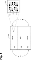
- FIG. 1 shows a high-level depiction of a lithium all-solid-state battery structure 100.
- the battery structure 100 is shown including a cathode 101, solid state electrolyte 102, and an anode 103.
- the arrows are illustrative of charge and recharge cycles.
- the anode may include a lithium metal, graphite, silicon, and/or other active materials that transfer electrons during charge/discharge cycles.
- the lithium reservoir may be a stabilized Li metal powder.
- the cathode 101 is shown in more detail in the exploded view 101', wherein the white circles labeled 110 represent a transition metal sulfide (e.g., FeS 2 or an mixture of FeS plus S).
- the gray circles labeled 111 represent solid state electrolyte (SSE) particles.
- SSE particles promote ionic conductive pathways in and out of the cathode 101.
- the black circles labeled 112 represent a conducting additive, such as acetylene black.
- the transition metal sulfide e.g., FeS plus S
- the transition metal sulfide may be mechanically mixed (e.g., using ball milling or other mechanical processes), and are not chemically combined.
- the chemistry of the cathode approximates FeS 2 on the first cycle. After 10 or more charge cycles, the cathode exhibits a behavior that is similar to that of the first cycle.
- lithium all-solid-state battery structure 100 may be implemented using any suitable transition metal sulfide plus sulfide combination, the following discusses a specific battery structure based upon synthetic iron disulfide.
- Synthetically prepared FeS 2 is characterized with field emission scanning electron microscopy (FESEM) and x-ray analysis.
- Figure 2 shows (a) a FESEM micrograph of synthetic FeS 2 that confirms cubic structure with wide 2-3 ⁇ m cubes, and (b) X-ray diffraction of synthetic pyrite.
- the FESEM micrograph shown in Figure 2(a) reveals cubic FeS 2 particles with 3 ⁇ m wide faces.
- the X-ray analysis of synthetically prepared FeS 2 shown in Figure 2(b) shows diffraction peaks that match well with indexed peaks.
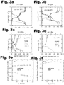
- Synthetic FeS 2 was tested in both an all-solid-state and liquid cell configuration. To achieve full utilization of FeS 2 , the cells are cycled to full discharge (1.0V) and full charge (3,0V). The results of cycling at ambient and moderate temperatures are shown in Figure 3 .
- Figure 3 shows FeS 2 cycled at ambient temperature (about 30°C) and moderately elevated temperature (about 60°C) in a liquid coin cell and in an all-solid-state configuration for: (a) solid-state at 30°C, (b) solid-state at 60°C, (c) liquid coin cell at 30°C, (d) a liquid coin cell at 60°C, (e) capacity retention comparison of cells cycled at 30°C, and (f) capacity retention comparison of cells cycled at 60°C. All cells except for the 30°C solid-state cell were cycled at a current of 144 ⁇ A which corresponds to a rate of C/10 for charge and discharge. The 30°C solid-state cell was cycled at rate of C/10 for the first cycle and C/20 (72 ⁇ A) for all subsequent cycles.
- Each reaction can occur at one voltage or two, depending at least in part on the kinetics of the system.
- the shoulder at 1.3V in the ambient temperature liquid cell may be attributed to an irreversible side reaction of FeS 2 intermediaries with the organic electrolyte.
- the initial discharge profile of the FeS 2 cells is much different than subsequent discharge profiles.
- the variation in discharge profiles may be due to the improved reaction kinetics of charge products compared to that of cubic- ⁇ mFeS 2 .
- Better kinetics may be due to changes in FeS 2 particle morphology and the electrochemical formation of a different phase of stoichiometric of FeS 2 like orthorhombic-FeS 2 (marcasite).
- Fe 0 takes the form of super-paramagnetic atoms or small aggregates of atoms of about 3.6nm in diameter.
- Nano-particles of Fe 0 have a high reactivity which is related to the nano-particle's large surface area. Should Fe 0 particles agglomerate into larger particles with smaller overall surface area, then these particles will have a lower reactivity. Without meaning to be limited by the theory, it may be the high reactivity of the Fe 0 nano-particles that maintains the electro-activity of Li 2 S. Of course, other theories are also possible.
- Fe 0 is susceptible to continuous agglomeration upon cycling. Agglomeration of Fe 0 results in the isolation of Li 2 S species and the observed capacity fade when cells are discharged to low voltages.
- An all-solid-state architecture can reduce or altogether prevent the agglomeration of Fe 0 nanoparticles.
- the atomic proximity of Fe 0 nanoparticles with Li 2 S maintains the electro-activity of Li 2 S without the excessive amount of conductive additive needed in S/Li 2 S based batteries.
- An all-solid-state architecture is also successful at confining polysulfides S n 2- formed when the electro-active species present at full charge are reduced.
- FeS 2 is not regenerated by the four electron oxidation of Fe 0 and Li 2 S. But the same is not true for molten salt FeS 2 cells, which operate reversibly at temperatures in excess of 400°C.
- subsequent charge and discharge cycles may proceed according to the following reactions: Fe 0 + Li 2 S ⁇ Li 2 FeS 2 + 2 Li + + 2 e ⁇ Li 2 FeS 2 ⁇ Li 2 ⁇ x FeS 2 + xLi + + xe ⁇ 0.5 ⁇ x ⁇ 0.8 Li 2 ⁇ x FeS 2 ⁇ FeS y + 2 ⁇ y S + 2 ⁇ x Li + + 2 ⁇ x e ⁇
- equation (5) may be better represented by equation (6) based on the results to be outlined below: Li 2 ⁇ x FeS 2 ⁇ 0.8 ortho ⁇ FeS 2 + 0.2 FeS 8 / 7 + 0.175 S + 2 ⁇ x Li + + 2 ⁇ x e ⁇
- Charge products at about 30-60°C are likely a multi-phase mixture of nano-particles of orthorhombic-FeS 2 , non-stoichiometric FeS y phases like pyrrhotite and elemental sulfur.
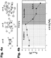
- the electrochemically active products resulting from sequential charge cycles simulate the FeS 2 chemistry as well as provide electrical conductivity within the electrode thus reducing the amount of conductive additive required. This conclusion is supported by the results of a DFT simulation shown in Figures 4-6 .
- Figure 5 shows: a) Coulometric titration results for a solid-state cell titrated at 60°C compared with the first, second, and tenth discharge profiles for a solid-state cell cycled at 60°C, b) shows dQ/dV of a solid-state cell cycled at 30°C, and c) shows deconvolution of the dQ/dV peaks at 2.1 and 2.2V with fitted peaks and residual.
- Figure 6 shows electrode material from the solid-state cell cycled at 60°C recovered after the twentieth charge for transmission electron microscope (TEM) analysis, where: (a) is a bright field TEM image of the twentieth cycle sample with darker areas corresponding to nano-crystalline orthorhombic-FeS 2 and lighter areas corresponding to an amorphous region composed of FeS y and elemental sulfur, and (b) is a high resolution (HR-) TEM of the twentieth cycle sample. FFT analysis matches with orthorhombic-FeS 2 along the [-110] zone axis.
- TEM transmission electron microscope
- electrochemically produced FeS 2 particles are nano-crystalline, then the greatly increased interfacial surface area facilitates a fast reaction rate despite poor Li + diffusivity.
- the diffusivity of Li + may also be improved by regenerating a phase other than cubie-FeS 2 .
- orthorhombic-FeS 2 has a more open structure than cubic-FeS 2 .
- the formation of orthorhombic-FeS 2 instead of cubic-FeS 2 may result in faster Li + diffusion, thus further increasing the reduction reaction kinetics,
- High resolution transmission electron microscopy can be used to support this understanding through direct observation of orthorhombic-FeS 2 nano-particles upon charge.
- electrode material was recovered from the solid-state cell cycled at about 60°C upon completion of the twentieth charge as can be seen in Figure 3(b) .
- This cell exhibits full utilization of FeS 2 so it is unlikely that a significant mass of electrochemically inactive synthetic cubic-FeS 2 remains in the cell by the twentieth charge.
- Figure 6(a) shows a bright field (BF) TEM image of the 20th cycled charged FeS 2 solid-state electrode. This image depicts nano-crystalline domains (darker) of 100-200nm in diameter encased by an amorphous material (lighter).
- FFT Fast Fourier transform
- the peak at about 2.2 V has an area of about 57.14 mAh g -1 while the peak at about 2.1V has an area of about 285.79 mAh g -1 .
- (2-y)S is directly reduced to Li 2 S, then the remaining capacity may be attributed to FeS y .
- the value of y can be determined to be about 0.085. If subsequent discharges follow equation (5), then the chemical formula of FeS y is about FeS 1.92 . If FeS y primarily takes the form of Fe 7 S 8 (pyrrhotite), then the chemistry of subsequent cycles likely follows equation (6),
- the charge products are likely a multiple phase mixture of nano-crystalline orthorhombic-FeS 2 , sulfur deficient phases of FeS y and elemental sulfur. Accordingly, the charge products are believed to be nano-crystalline orthorhombic-FeS 2 encased in amorphous sulfur deficient FeS y and sulfur (see Figure 6(a) ).
- FeS y phases and elemental sulfur may explain the amorphous domains observed in the high resolution TEM images.
- the presence of sulfur deficient FeS y phases and the observation of orthorhombic-FeS 2 is consistent.
- Orthorhombic-FeS 2 exhibits very weak temperature independent paramagnetism. For this reason, it is likely that 57 Fe Mössbauer spectroscopy used in previous studies was not capable of distinguishing orthorhombic-FeS 2 from other strong temperature dependent paramagnetic phases like FeS y and cubic-FeS 2 .
- Fe 7 S 8 is ferrimagnetic while FeS is paramagnetic. It is noted that ferrimagnetism is a much stronger effect.
- the FeS 2 synthetic methodology used solvothermal reaction conditions. Dielectric heating for the reaction was provided with a microwave reactor. Microwave heating was selected because of its high reproducibility and the ability for automation, making this methodology amenable to high throughput syntheses.
- the microwave used for this example was a Discover SP (CEM Inc.).
- the sample was irradiated with 75 W of power until reaching 190°C, as measured by an infrared detector. The heating took about 7 minutes, and was held at this temperature for 12 hours. Approximately 690 kPa of autogenous pressure was generated. After the reaction was finished, the product was cooled by compressed air.
- Synthetic FeS 2 was characterized by Cu-K ⁇ x-ray diffraction (XRD) measurement, FESEM microscopy (JEOL JSM-7401F), and Raman spectroscopy (Jasco NRS-3100).
- the composite positive electrode had a 10:20:2 weight ratio mixture of synthetically prepared FeS 2 , 77.5Li 2 -22.5P 2 S 5 , and carbon black (Timcal Super C65), respectively.
- the composite positive electrode was mixed using an agate mortar and pestle.
- Stabilized lithium metal powder (SLMP) was used as the negative electrode (FMC Lithium Corp.).
- the construction of solid-state cells utilized a titanium-polyaryletheretherketone (PEEK) test cell die. 200mg of solid electrolyte powder was pressed at 1 metric ton in the PEEK cell die. 5mg of composite positive electrode and the stabilized lithium metal powder were then attached to opposite sides of the solid electrolyte layer by pressing at 5 metric tons.
- Liquid cells were fabricated by spreading an electrode slurry with a 6:2:2 weight ratio of synthetic FeS 2 , polyvinylfluorine (PVDF) binder (Alfa Aesar) and acetylene black (Alfa-Aesar, 50% compressed) respectively.
- PVDF binder was first dissolved into N-methyl-2-Pyrrolidone (NMP) (Alfa-Aesar) solvent FeS 2 and acetylene black were then stirred into the PVDF binder.
- NMP N-methyl-2-Pyrrolidone
- a 50 ⁇ m thick layer of slurry was spread on onto aluminum foil (ESPI Metals, 0.001" thick) and dried at 60°C in a single wall gravity convection oven (Blue M) for 5 hours.
- the electrode sheet was then calendared with a Durston rolling mill to 75% of the total thickness. 9/16" diameter electrodes were punched and heat treated at 200°C in an Argon environment overnight. FeS 2 electrodes were then assembled into coin cells with a lithium foil negative electrode (Alfa-Aesar, 0.25mm thick) and 1M LiPF 4 electrolyte.
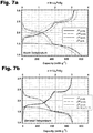
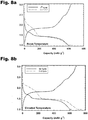
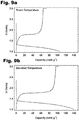
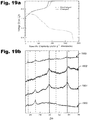
- Figures 7-9 are plots showing actual data obtained for Example 2. Specifically, Figure 7 shows charge/discharge profiles for FeS 2 in a solid state lithium battery, made from microwave synthesis. Figure 8 shows charge/discharge profiles for in-situ formation of FeS 2 upon cycling of FeS+S combined by planetary ball milling (cycled at C/10). The top plot in Figure 9 shows the performance of FeS, with significantly lowered capacity and a lack of voltage plateaus correlating to Eq. 7 and 8 below. Upon discharge at room temperature, a slightly lower voltage is observed due to internal resistance in the cell, and similarly for charging with a slightly higher voltage. A significant decrease in reversibility is also observed, with first cycle coulombic efficiency of both room temperature and elevated temperature FeS cells below 75%, The bottom plot in Figure 8 shows a first cycle of FeS at (a) room temperature and (b) elevated temperature.
- solid state batteries utilizing highly conducting sulfide based solid electrolytes were used for reversible cycling of FeS 2 electrodes in both room temperature (25°C) and elevated temperature environments (60°C) as shown in Figure 7 . Furthermore, it was shown that there is no capacity loss for increasing rates up to C/8 for elevated temperature testing.
- the first cycle shows the reaction formation of Li 2 S and Fe down to 1.0V. Reversible cycling is allowed by the highly reactive iron allowing successful de-Lithiation of Li 2 S, and subsequent formation of various Li-Fe-S compounds according to the following equations which are visible in the charging profile.
- FeS 2 was formed in-situ during the first cycle (and also occurs over the course of many cycles), utilizing stoichiometric combinations of other materials. FeS and S were mixed either by mortar and pestle grinding, or by ball milling to produce an active material that is simply the addition of both, without formation of FeS 2 .
- Thermoelectrochemical activation of solid state electrolyte is also disclosed herein.
- the solid state electrolyte e.g., Li 2 S
- sulfide-based solid electrolytes including but not limited to xLi 2 S-(100 - x)P 2 S 5 .
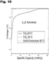
- Figure 10 is a plot illustrating that the activation of Li 2 S is based at least in part on both the ionic and electronic conductivity of TiS 2 , as well as added thermal energy (e.g., about 60°C).
- the specific charge capacities shown in Figure 10 are based on the total mass of TiS 2 solid electrolyte and acetylene black. Even at elevated temperature the composite with only solid electrolyte shows no capacity. Likewise, the composite with TiS 2 also shows no capacity when charged at room temperature.
- the composite electrode with TiS 2 exhibited a charge capacity of 13 mAh g -1 when charged at an elevated temperature of about 60°C. This corresponds to a specific charge capacity of about 40mAh g -1 based upon the TiS 2 mass.
- the only source of lithium in these cells was Li 2 S. Under an applied current at elevated temperature, it is believed that otherwise inert Li 2 S is activated by the highly ionic and electronic conductive character of TiS 2 , Other transition metal sulfides have similar material properties as TiS 2 , and may be useful in a similar Li 2 S activation process.
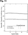
- Figure 11 shows results of thermo-electrochemical activation of Li 2 S using nano-LiTiS 2 .
- Figure 11 is a plot showing cells with a 10:20:1 wt% nano-LiTiS 2 : 80Li 2 S-20P 2 S 5 :acetylene black composite electrode cycled at C/5 and C/5 charge and discharge rates.
- the bottom data series shows the cell cycled at 30°C (without thermal-electrochemical activation), and the top data series (triangles) shows the cell initially charged at 60°C before being removed to room temperature.
- the nano-LiTiS 2 was synthesized using mechano-chemical milling process involving Li 3 N decomposition.
- the composite electrodes are a 10:20:1 weight ratio mixture of nano-LiTiS 2 :80Li 2 S-20P 2 S 5 :acetylene black.
- the cells in this example have an In metal negative electrode and are cycled at a rate of C/5 for both charge and discharge. However, the initial charge and discharge cycles are both conducted at a rate of C/10. Specific charge capacities presented are based upon the mass of LiTiS 2 initially present in the composite electrode.
- the first cell cycled at room temperature exhibits a very stable capacity of about 230 mAh g -1 after about forty cycles.
- the second cell undergoes an initial elevated temperature activation charge at about 60°C. It is then moved to room temperature (about 30°C) for the first discharge and all cycles thereafter.
- This cell exhibits a 345 mAh g -1 discharge capacity after about the fortieth cycle. This represents about a 119 mAh g -1 (or about a 53%) increase in capacity over the theoretical capacity of LiTiS 2 of 226mAh g -1 .
- nano-LiTiS 2 The increase in capacity observed with nano-LiTiS 2 is much larger than the 40mAh g -1 excess capacity achieved with the TiS 2 -80Li 2 S:P 2 S 5 -acetylene black composite.
- the greater surface area of the nano-LiTiS 2 particles is thought to more easily facilitate the activation of Li 2 S in the solid electrolyte. Supporting the previous finding, the rate performance of nano-LiTiS 2 composite electrodes is shown in Figure 12 .
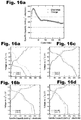
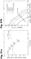
- Figures 12(a) -(d) are plots of an illustrative rate study of a 10:20:1 wt% LiTiS 2 : 80Li 2 S-20P 2 S 5 :acetylene black composite electrode, where (a) and (b) are at 30°C, and (c) and (d) are at 60°C.
- the plots in Figures 12(a)-(d) confirm the repeatability of results shown in Figure 11 .
- the cell cycled at an elevated temperature exhibits discharge capacities in excess of 160mAhg -1 greater than the theoretical capacity of 226 mAhg -1 for LiTiS 2 .
- the cells in this example have a Li metal negative electrode to facilitate fast ion transfer, It is noted that the cell cycled at elevated temperature has a specific discharge capacity of nearly 390 mAh g -1 at a rate of C/2 while the cell cycled room temperature only exhibits a capacity of 210 mAh g -1 at C/2. Repeatedly charging at elevated temperature activates Li 2 S in the solid electrolyte, providing excess capacity.
- Figures 13(a) -(b) are plots showing cycling data for a lithium metal cell.
- the plots show cycling data for a lithium metal cell with a 10:20:1 wt% FeS 8/7 + S:77.5Li 2 S-22.5P 2 S 5 :acetylene black composite cathode cycled at 60°C.
- the cell gains capacity during the first 10 cycles.
- the increase in capacity is attributed to the S/Li 2 S redox reaction.
- the activation of excess sulfur is responsible for the evolution of a voltage plateau at about 2.2V.
- the cell has a specific discharge capacity of about 807 mAh g -1 on the first discharge, but a specific discharge capacity of 1341 mAh g -1 by the ninth cycle. This represents an activation of about 534 mAh g -1 .
- the activated capacity can be attributed to the evolution of the S/Li 2 S reduction plateau at about 2.2V.
- the particular solid electrolyte system in this example is xLi 2 S-(100-x)P 2 S 5 .
- this technique is applicable to any Li 2 S containing sulfide based electrolyte system is not limited to Li 2 S-GeS 2 -P 2 S 5 or Li 2 S-SiS 2 .
- These solid electrolytes are known as glass ceramics.
- electrolyte synthesis e.g., by melt-quenching or mechano-chemical milling
- Li 2 S is incorporated into glass formers not limited to GeS 2 , P 2 S 5 , and SiS 2 .
- Superionically conducting crystalline phases can also be precipitated in a glassy matrix upon subsequent heat treatment. It is also possible, that these crystalline phases may decompose and result in some excess capacity.
- Figure 14 are x-ray diffraction (XRD) spectra of an example 80Li 2 S-20P 2 S 5 solid electrolyte, example 10:20:1 wt% LiTiS 2 :80Li 2 S-20P 2 S 5 :acetylene black composite electrodes, and indexed spectra for Li 1.0 TiS 2 and Li 2 S.
- the XRD spectra of the solid electrolyte in this illustration shows Li 2 S peaking at about 27 and about 31.2 degrees, indicating that there are some Li 2 S domains still present in the solid electrolyte. It is believed that the additional capacity is a result of reacting excess Li 2 S in the solid electrolyte. It is expected that the 77.5Li 2 S-22.5P 2 S 5 solid electrolyte has less excess Li 2 S to participate in activation reactions.
- the process described herein is analogous, but is also somewhat different. That is, Cu reacts to form Cu y S, while TiS 2 remains chemically/structurally stable. TiS 2 is an intercalation electrode material, while Cu y S is a conversion battery material. TiS 2 succeeds in electrochemically activating excess Li 2 S because it is both highly ionically and electronically conductive.
- the process described herein is based on an initial charging at elevated temperature, as no excess capacity is observed at room temperature.
- FeS 2 , FeS x , or FeS x + S The iron sulfide (FeS 2 , FeS x , or FeS x + S) systems disclosed herein are more like the Cu y S electrodes.
- FeS 2 is not chemically/structurally stable like TiS 2 . Instead, FeS 2 reacts with 4Li + in a conversion reaction to form the completely reduced products of Fe 0 and 2Li 2 S.
- Fe 0 acts as a catalyst for the oxidation of Li 2 S
- the products of oxidation include various electronically conducting phases of FeS x . These phases then help to electrochemically activate excess Li 2 S present in the solid electrolyte.
- the lithium all-solid-state battery described above which may be thermally activated as described above, may also be made using a high capacity conversion battery materials (e.g., FeS 2 ) equivalent. Examples are described in the following discussing as in-situ electrochemical formation of a FeS 2 phase and reversible utilization of a glass electrolyte for higher overall electrode energy density. However, the lithium all-solid state battery is not limited to such an implementation.
- a high capacity conversion battery materials e.g., FeS 2
- synthesis of the iron sulfide based all-solid-state composite electrodes can be by a three step planetary ball milling procedure (Across International, PQ-N2).
- An example 77.5Li 2 S-22.5P 2 S 5 (molar ratio) glass electrolyte can be prepared by milling about 0.832g Li 2 S (Aldrich, 99.999%, reagent grade) and about 1.168g P 2 S 5 , (Aldrich, 99%) in a 500mL stainless steel vial (Across International) with two stainless steel balls (having about a 16mm diameter) and twenty stainless steel balls (having about a 10mm diameter) at about 400 rpm for about 20 hours.
- the 1:1 molar ratio FeS:S active material composite (denoted as FeS + S) can be prepared by milling about 0.733g FeS (Aldrich, technical grade) and about 0.267g Sulfur (Aldrich.. 99.98%) in a 100mL agate jar (Across International) with five agate balls (having about a 10mm diameter) and fifty agate balls (having about a 6mm diameter) at about 400 rpm for about 20 hours.
- the composite electrode can be synthesized by milling a ratio of prepared FeS + S, 77.5Li 2 S-22.5P 2 S 5 , and carbon black conductive additive (Timcal, C65) in a 100mL agate jar with five agate balls (having about a 10mm diameter) and fifty agate balls (having about a 6mm diameter) at about 400 rpm for about 18 minutes.
- the working electrode is about 5mg of the mechanically prepared FeS + S based composite electrode, In this example, about 5mg of stabilized lithium metal powder (SLMP) was used as the counter electrode (FMC Lithium Corp., Lectro Max Powder 100).
- the shell of the solid state battery was a titanium-polyaryletheretherketone (PEEK) test cell die. To fabricate each cell, the glass electrolyte powder was first compressed at about 5 metric tons inside the PEEK cell die to form the separator pellet. In this example, about 5mg of composite positive electrode and the SLMP were then attached to opposite sides of the glass electrolyte pellet with about 5 metric tons force.
- the FeS in these batteries was prepared by mechanically milling about 2g of FeS in a 100mL agate jar (Across International) with five agate balls (having about a 10mm diameter) and fifty agate balls (having about a 6mm diameter) at about 400 rpm for about 20 hours.
- the cells used to electrochemically prepare the cycled XRD samples had a 165 mg FeS composite cathode and an InLi alloy anode. These cells operate at a lower potential because the InLi alloy has a potential of about 0.62V vs. Li + /Li.
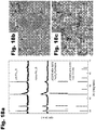
- Figure 15 shows (a) XRD of FeS + S composite active material and FeS precursor with indexed reflections for Fe 7 S 8 and FeS.
- the FeS precursor material is likely a multiphase mixture of FeS and an iron deficient Fe 1-x S phase. After mechanochemical milling, only reflections for FeS and S are observed which indicates that no solid state reactions occurred to form FeS 2 ; and (b) is an FESEM micrograph of the FeS + S composite active material.
- XRD measurement presented in Figure 15(a) shows that the FeS precursor is composed partly of FeS (Triolite). However, the precursor also exhibits ferrimagnetism, which indicates that the sample is likely a multiphase mixture of FeS and an iron deficient phase like Fe 7 S 8 (Pyrrhotite). An unidentified peak at 44.64° suggests that other phases may be present as well.
- FIG. 16 shows (a) cyclic stability of a FeS + S/Li battery. Assuming that the active material composition of FeS + S has a theoretical specific capacity of 900 mAh g -1 , the electrode's specific capacity should not exceed 281 mAh g -1 . Excess capacity is evidence for the electrochemical utilization of the 77.5Li 2 S-22.5P 2 S 5 glass electrolyte component; and (b)-(e) are voltage profiles for cycles 1, 2, 10, 20, 30, 40, 60, and 150 of the same battery. The variability of voltage profiles with respect to cycle number suggests an evolving electrochemistry.
- Figure 16(a) shows the cyclic stability of a 5mg electrode cycled at 60°C with a current of 144 ⁇ A.
- the electrode exhibits an initial discharge of 320 mAh g -1 . or 1020 mAh g -1 based only on the mass fraction of the FeS + S nano-composite active material.
- the theoretical capacity of FeS + S should only be approximately 900 mAh g -1 , however, the other iron deficient phases present in the FeS precursor affect the actual theoretical value.
- the electrode After the initial discharge, the electrode rapidly gains capacity until a maximum capacity of 550 mAh g -1 and maximum energy density of 1040 Wh kg -1 are achieved by the 16 th cycle.
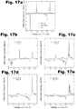
- FIG. 17 shows (a) dQ/dV profiles for bulk-type all-solid-state Li metal batteries with FeS, syn-FeS 2 , and S composite cathodes; and (b)-(e) dQ/dV profiles for cycles 1, 2, 10, 20, 30, 40, 60 and 150 of an example FeS + S/Li battery. It is observed that the evolution of three parallel redox chemistries accounts for the changing capacity of the battery. Twinning of reduction peaks in voltage ranges between 2.13 - 2.19 and 1.56 - 1.51 V provides evidence for the in-situ electrochemical formation of a FeS 2 phase.
- Figure 17a shows the characteristic behavior of FeS, FeS 2 , and S in an ASSLB.
- the FeS 2 chemistry is characterized by dominant reduction peaks at 2.20, 2.14 and 1.49 V, while S is characterized by a reduction peak at 2.2V and FeS by a peak at 1.55V.
- the dQ/dV profiles in Figure 17b for the first and second cycles show evidence for the reduction of only FeS and S. As the cell's capacity increases, so too does the complexity of the voltage profiles.
- the dQ/dV profiles in Figure 17c show evidence for the reduction of FeS, S and FeS 2 .
- the reduction of FeS 2 is apparent due to the twinning of reduction peaks in voltage ranges of 2.14 - 2.19 V and 1.51 - 1.56 V. This is the first time evidence for the in-situ electrochemical formation of FeS 2 has been presented.
- capacity fade is correlated to the decline of peaks associated with Fe 0 ⁇ Fe 2+ reduction and oxidation.
- the dQ/dV profiles in Figure 17d for the thirtieth and fortieth cycles during the capacity fade phase show that Fe redox peaks disappear while the S redox peaks remain relatively stable.
- the dQ/dV profiles in Figure 17e for the electrode achieve a degree of stability. Extended cycling capacity loss is associated with continued fade of the Fe redox peaks and the fade of S redox peaks.
- the electrochemical utilization of the 77.5Li 2 S:22,5P 2 S 5 glass electrolyte can be understood with reference to ex-situ XRD measurement of FeS based electrodes.
- FeS was used instead of FeS + S to simplify the analysis.
- a glass electrolyte was used because the absence of ceramic electrolyte diffraction patterns also simplifies the analysis.
- the FeS used in this experiment was mechanically milled.
- Figure 18 shows (a) XRD of FeS before and after milling indicates that no phase changes occur during milling, (b) an FESEM micrograph of FeS as received from the vendor, and (c) an FESEM micrograph of Fe 1-x S after mechanical milling.
- the XRD and FESEM analysis confirm that the mechanical milling provides the needed size reduction. Utilization of nano-FeS helps obtain good contact with the glass electrolyte.
- Figure 19(a) shows voltage profiles for two initially overcharged FeS/Liln batteries. Composite electrodes were collected for XRD after full overcharge (solid) and full discharge (dashed). As seen in Figure 19(a) , the FeS composite electrode was recovered after an initial overcharge (solid) and after full discharge (dashed) ( Figure 4a ).
- the diffraction pattern for the glass electrolyte 1950 includes reflections for Li 2 S (dashed).
- the diffraction pattern for an uncycled composite electrode 1951 includes reflections for Li 2 S and FeS (solid). After an initial overcharge 1952, the reflections for Li 2 S disappear. When an electrode is discharged after an initial overcharge 1953, reflections for FeS disappear and weak reflections for Li 2 S are once again detected. The reduced intensity of the Li 2 S reflections in this sample is believed to be due to the small size of electrochemically precipitated Li 2 S particles.
- the percentage of Li 2 S oxidized in the cell presented in Figures 16 and 17 can be estimated by assuming that all of the FeS + S was electrochemically utilized and by acknowledging that the highest achieved capacity is 2.8 mAh. A fraction of this capacity can be attributed to utilization of the glass electrolyte at the electrode/glass electrolyte separator interface, as indicated by Figure 21 .
- Figure 20 shows the first through seventeenth voltage profiles of a FeS/Liln battery where the cathode is composed entirely of 5mg of nano-FeS.
- FeS should reversibly exhibit only a single plateau.
- this battery develops a higher voltage plateau at approximately 1.4 V versus. inLi.
- the evolution of the second plateau can be attributed to the electrochemical utilization of Li 2 S in the glass electrolyte at the electrode/glass electrolyte separator interface.
- up to 300 ⁇ Ah of capacity can be attributed to the utilization of glass electrolyte separator. This interface utilization effect may lead to an overestimation of specific capacity and contribute to the observed excess capacity.
- Utilization of the glass electrolyte separator may lead to an overestimation of specific capacity and contribute to the observed excess capacity especially when the electrode is very small like it is in this case.
- the FeS + S component can account for 1.45 mAh of the maximum capacity. Without accounting for utilization of the glass electrolyte separator, the remaining capacity indicates that 1.16 mg, or 86%, of Li 2 S in the glass electrolyte is electrochemically utilized.
- Figure 21 shows (a) specific discharge capacity of a battery as a function of applied current, and (b) voltage profiles of the same battery as a function of applied current.
- the electrode maintains a specific capacity of 200 mAh g -1 with an applied current of about 2.40 mA.
- the P 2 S 5 component of the glass electrolyte may be electrochemically utilized as well. Utilization of P 2 S 5 also explains why capacity increases during discharge cycles, and not only during the charge cycles when excess Li 2 S is initially oxidized to S.
- Electrolyte sensitivity is emphasized by the results of another study that did not observe electrolyte utilization.
- nano-FeS was used as an active material and Li 2 S was a precursor for their electrolyte.
- the electrolyte was a different composition, thio-LISICON Li 3,25 Ge 0.25 P 0.75 S 4 , and was prepared by melt quenching instead of mechanochemical milling. Previous work also did not show evidence for electrochemical activation of the glass electrolyte. In this study, three 5 micron cubes of synthetic FeS 2 were used as the active material.
- Cubic-FeS 2 is also a semiconductor with a much lower electronic conductivity than that of the ferrimagnetic Fe 1-x S precursor used in this study.
- the decision to mechanically combine ⁇ m-Cu powder with S or Li 2 S can be further improved.
- the conversion materials, FeF 2 and CuF 2 suggest that a nano-structured network of reduced metallic nanoparticles may be employed for good reversibility, A mechanical mixture with micron active metal particles is therefore not ideal for good reversibility or for good electrolyte utilization.
- electrochemically reduced nano-active metal particles may be used due to the better atomic proximity to other reduced species, as well as to the electrolyte particles, to further enhance reversibility and effective electrolyte utilization.
Landscapes
- Chemical & Material Sciences (AREA)
- Electrochemistry (AREA)
- General Chemical & Material Sciences (AREA)
- Chemical Kinetics & Catalysis (AREA)
- Engineering & Computer Science (AREA)
- Manufacturing & Machinery (AREA)
- Inorganic Chemistry (AREA)
- Composite Materials (AREA)
- Materials Engineering (AREA)
- Physics & Mathematics (AREA)
- Condensed Matter Physics & Semiconductors (AREA)
- General Physics & Mathematics (AREA)
- Battery Electrode And Active Subsutance (AREA)
- Secondary Cells (AREA)
- Conductive Materials (AREA)
Applications Claiming Priority (3)
| Application Number | Priority Date | Filing Date | Title |
|---|---|---|---|
| US201261585098P | 2012-01-10 | 2012-01-10 | |
| US201261590494P | 2012-01-25 | 2012-01-25 | |
| PCT/US2013/020819 WO2013133906A2 (en) | 2012-01-10 | 2013-01-09 | Lithium all-solid-state battery |
Publications (3)
| Publication Number | Publication Date |
|---|---|
| EP2803108A2 EP2803108A2 (en) | 2014-11-19 |
| EP2803108A4 EP2803108A4 (en) | 2015-07-08 |
| EP2803108B1 true EP2803108B1 (en) | 2018-11-28 |
Family
ID=49117481
Family Applications (1)
| Application Number | Title | Priority Date | Filing Date |
|---|---|---|---|
| EP13757981.9A Active EP2803108B1 (en) | 2012-01-10 | 2013-01-09 | Lithium all-solid-state battery |
Country Status (4)
| Country | Link |
|---|---|
| US (4) | US20140377664A1 (ja) |
| EP (1) | EP2803108B1 (ja) |
| JP (2) | JP2015503837A (ja) |
| WO (1) | WO2013133906A2 (ja) |
Families Citing this family (17)
| Publication number | Priority date | Publication date | Assignee | Title |
|---|---|---|---|---|
| US11876180B2 (en) * | 2019-11-06 | 2024-01-16 | Enevate Corporation | Silicon-based energy storage devices with metal sulfide containing electrolyte additives |
| CN103427125B (zh) * | 2012-05-15 | 2016-04-13 | 清华大学 | 硫基聚合物锂离子电池的循环方法 |
| US9692039B2 (en) | 2012-07-24 | 2017-06-27 | Quantumscape Corporation | Nanostructured materials for electrochemical conversion reactions |
| WO2015076935A2 (en) * | 2013-09-30 | 2015-05-28 | The Regents Of The University Of Colorado, A Body Corporate | All-solid-state cathode materials, cathodes, batteries and methods |
| KR102384822B1 (ko) | 2014-02-25 | 2022-04-08 | 퀀텀스케이프 배터리, 인코포레이티드 | 삽입 및 변환 물질 양자 모두를 갖는 하이브리드 전극 |
| WO2016025866A1 (en) | 2014-08-15 | 2016-02-18 | Quantumscape Corporation | Doped conversion materials for secondary battery cathodes |
| DE102015210402A1 (de) * | 2015-06-05 | 2016-12-08 | Robert Bosch Gmbh | Kathodenmaterial für Lithium-Schwefel-Zelle |
| CN105206841B (zh) * | 2015-08-28 | 2018-06-12 | 清华大学 | 一种用于锂硫电池正极中的黄铁矿类添加剂 |
| US11621420B2 (en) | 2016-03-11 | 2023-04-04 | University Of Houston System | High ionic conductivity rechargeable solid state batteries with an organic electrode |
| CN109478686A (zh) * | 2017-03-31 | 2019-03-15 | 丰田自动车欧洲公司 | 用于锂离子蓄电池的充电保护的系统和方法 |
| US10854877B2 (en) * | 2017-08-25 | 2020-12-01 | Samsung Electronics Co., Ltd. | All-solid-state secondary battery |
| JP7164939B2 (ja) * | 2017-08-25 | 2022-11-02 | 株式会社サムスン日本研究所 | 全固体型二次電池 |
| US11367867B2 (en) * | 2017-09-04 | 2022-06-21 | Industry-University Cooperation Foundation Hanyang University | Positive electrode for metal-sulfur battery, manufacturing method therefor, and metal-sulfur battery comprising the same |
| JP7035591B2 (ja) * | 2018-02-14 | 2022-03-15 | 東京電力ホールディングス株式会社 | リチウム硫黄固体電池の充電方法 |
| CN108878830B (zh) * | 2018-06-26 | 2021-08-17 | 中国科学院宁波材料技术与工程研究所 | 一种室温固态锂硫电池用电极材料及其制备方法以及固态锂硫电池 |
| US11325096B2 (en) | 2018-07-24 | 2022-05-10 | Toyota Motor Engineering & Manufacturing North America, Inc. | Microwave synthesis of lithium thiophosphate composite materials |
| CN109920955B (zh) * | 2019-04-05 | 2021-12-14 | 浙江理工大学 | 一种应用于锂硫电池隔层的碳化铁复合纳米碳纤维膜及其制备方法 |
Family Cites Families (18)
| Publication number | Priority date | Publication date | Assignee | Title |
|---|---|---|---|---|
| US3907589A (en) * | 1974-01-18 | 1975-09-23 | Us Energy | Cathode for a secondary electrochemical cell |
| JPH04269453A (ja) * | 1991-02-26 | 1992-09-25 | Matsushita Electric Ind Co Ltd | 非水電解液二次電池 |
| JPH06275312A (ja) * | 1993-03-22 | 1994-09-30 | Matsushita Electric Ind Co Ltd | 全固体リチウム電池 |
| IL105341A (en) * | 1993-04-08 | 1996-12-05 | Univ Ramot | Composite solid electrolyte and alkali metal batteries using this electrolyte |
| EP0704920B1 (en) | 1994-09-21 | 2000-04-19 | Matsushita Electric Industrial Co., Ltd. | Solid-state lithium secondary battery |
| US6022640A (en) * | 1996-09-13 | 2000-02-08 | Matsushita Electric Industrial Co., Ltd. | Solid state rechargeable lithium battery, stacking battery, and charging method of the same |
| JPH11297359A (ja) * | 1998-04-15 | 1999-10-29 | Matsushita Electric Ind Co Ltd | 全固体リチウム二次電池 |
| JP2004179160A (ja) * | 2002-11-26 | 2004-06-24 | Samsung Sdi Co Ltd | リチウム−硫黄電池用正極 |
| KR101099225B1 (ko) * | 2004-02-13 | 2011-12-27 | 산요덴키가부시키가이샤 | 비수성 전해질 2차 전지용 양극 및 그의 제조 방법 및비수성 전해질 2차 전지 및 그의 제조 방법 |
| JP2006164695A (ja) * | 2004-12-06 | 2006-06-22 | Sanyo Electric Co Ltd | 非水電解質二次電池 |
| WO2009038037A1 (ja) * | 2007-09-21 | 2009-03-26 | Idemitsu Kosan Co., Ltd. | 耐熱性正極合材及びそれを用いた全固体リチウム二次電池 |
| JP5126834B2 (ja) * | 2008-03-12 | 2013-01-23 | 独立行政法人産業技術総合研究所 | 金属硫化物と金属酸化物の複合体およびその製造方法 |
| GB2464455B (en) * | 2008-10-14 | 2010-09-15 | Iti Scotland Ltd | Lithium-containing transition metal sulfide compounds |
| JP5158008B2 (ja) * | 2009-04-28 | 2013-03-06 | トヨタ自動車株式会社 | 全固体電池 |
| JP2011154900A (ja) * | 2010-01-27 | 2011-08-11 | Toyota Motor Corp | 全固体電池 |
| WO2011105574A1 (ja) * | 2010-02-26 | 2011-09-01 | 日本ゼオン株式会社 | 全固体二次電池及び全固体二次電池の製造方法 |
| US9397365B2 (en) * | 2010-03-26 | 2016-07-19 | Toyota Jidosha Kabushiki Kaisha | Solid electrolyte material and all solid-state lithium secondary battery |
| KR20120010552A (ko) * | 2010-07-26 | 2012-02-03 | 삼성전자주식회사 | 고체 리튬 이온 이차 전지 및 이에 사용될 수 있는 전극 |
-
2013
- 2013-01-09 WO PCT/US2013/020819 patent/WO2013133906A2/en active Application Filing
- 2013-01-09 US US14/371,500 patent/US20140377664A1/en not_active Abandoned
- 2013-01-09 JP JP2014552264A patent/JP2015503837A/ja active Pending
- 2013-01-09 EP EP13757981.9A patent/EP2803108B1/en active Active
-
2016
- 2016-12-27 US US15/391,442 patent/US20170331148A1/en not_active Abandoned
-
2017
- 2017-04-04 JP JP2017074176A patent/JP6968563B2/ja active Active
-
2019
- 2019-11-27 US US16/698,066 patent/US11283106B2/en active Active
-
2022
- 2022-02-15 US US17/672,555 patent/US11870032B2/en active Active
Non-Patent Citations (1)
| Title |
|---|
| None * |
Also Published As
| Publication number | Publication date |
|---|---|
| JP2017130465A (ja) | 2017-07-27 |
| EP2803108A2 (en) | 2014-11-19 |
| US20170331148A1 (en) | 2017-11-16 |
| EP2803108A4 (en) | 2015-07-08 |
| US20140377664A1 (en) | 2014-12-25 |
| WO2013133906A3 (en) | 2013-12-19 |
| US20200099095A1 (en) | 2020-03-26 |
| US20220223907A1 (en) | 2022-07-14 |
| JP2015503837A (ja) | 2015-02-02 |
| JP6968563B2 (ja) | 2021-11-17 |
| US11283106B2 (en) | 2022-03-22 |
| WO2013133906A2 (en) | 2013-09-12 |
| US11870032B2 (en) | 2024-01-09 |
Similar Documents
| Publication | Publication Date | Title |
|---|---|---|
| US11870032B2 (en) | Lithium all-solid-state battery | |
| Recham et al. | A 3.6 V lithium-based fluorosulphate insertion positive electrode for lithium-ion batteries | |
| US8168329B2 (en) | Electrochemical composition and associated technology | |
| Wang et al. | Nanostructured nickel sulfide synthesized via a polyol route as a cathode material for the rechargeable lithium battery | |
| US20080138710A1 (en) | Electrochemical Composition and Associated Technology | |
| Cheah et al. | Chemical lithiation studies on combustion synthesized V2O5 cathodes with full cell application for lithium ion batteries | |
| Molenda | Material problems and prospects of Li-ion batteries for vehicles applications | |
| WO2015057678A1 (en) | Sub-stoichiometric, chalcogen-containing-germanium, tin, or lead anodes for lithium or sodium ion batteries | |
| Zhang et al. | CuSbS2 nanobricks as electrode materials for lithium ion batteries | |
| Ng et al. | Spray-pyrolyzed silicon/disordered carbon nanocomposites for lithium-ion battery anodes | |
| Gandi et al. | SnO-GeO2-Sb2O3 glass anode network mixed with different Ba2+ fractions: investigations on Na-ion storage capacity and stability | |
| Fu et al. | Electrochemical properties of Cu2S with ether-based electrolyte in Li-ion batteries | |
| Yuan et al. | Na2Co3 [Fe (CN) 6] 2: a promising cathode material for lithium-ion and sodium-ion batteries | |
| EP2860801B1 (en) | Electrochemical composition and associated technology | |
| Pleuksachat et al. | Dynamic phase transition behavior of a LiMn0. 5Fe0. 5PO4 olivine cathode material for lithium-ion batteries revealed through in-situ X-ray techniques | |
| Akella et al. | Tailoring Nickel-Rich LiNi0. 8Co0. 1Mn0. 1O2 Layered Oxide Cathode Materials with Metal Sulfides (M2S: M= Li, Na) for Improved Electrochemical Properties | |
| Nag et al. | La-doped LiMnPO4/C cathode material for Lithium-ion battery | |
| Zhang et al. | Electrochemical and thermal characterization of Li4Ti5O12|| Li3V2 (PO4) 3 lithium ion battery | |
| Mohsin et al. | Enabling the Electrochemical Performance of Maricite-NaMnPO 4 and Maricite-NaFePO 4 Cathode Materials in Sodium-Ion Batteries | |
| Kim et al. | Visualization of the phase propagation within carbon-free Li4Ti5O12 battery electrodes | |
| Wang et al. | In-situ synthesized cathode prelithiation additive to compensate initial capacity loss for lithium ion batteries | |
| Helen et al. | Magnesium sulphide as anode material for lithium-ion batteries | |
| Xue et al. | Cu7S4 superionic with liquid-like mobility of copper ions for high-performance room-temperature rechargeable magnesium batteries | |
| Minakshi et al. | LiNiPO4 aqueous rechargeable battery | |
| Sandu et al. | Comparison of the electrochemical behaviour of SnO 2 and PbO 2 negative electrodes for lithium ion batteries |
Legal Events
| Date | Code | Title | Description |
|---|---|---|---|
| PUAI | Public reference made under article 153(3) epc to a published international application that has entered the european phase |
Free format text: ORIGINAL CODE: 0009012 |
|
| 17P | Request for examination filed |
Effective date: 20140716 |
|
| AK | Designated contracting states |
Kind code of ref document: A2 Designated state(s): AL AT BE BG CH CY CZ DE DK EE ES FI FR GB GR HR HU IE IS IT LI LT LU LV MC MK MT NL NO PL PT RO RS SE SI SK SM TR |
|
| DAX | Request for extension of the european patent (deleted) | ||
| A4 | Supplementary search report drawn up and despatched |
Effective date: 20150609 |
|
| RIC1 | Information provided on ipc code assigned before grant |
Ipc: H01M 10/0525 20100101ALI20150602BHEP Ipc: H01M 10/44 20060101ALI20150602BHEP Ipc: H01M 10/0562 20100101ALI20150602BHEP Ipc: H01M 4/36 20060101ALI20150602BHEP Ipc: H01M 10/39 20060101AFI20150602BHEP Ipc: H01M 4/38 20060101ALI20150602BHEP Ipc: H01M 4/136 20100101ALI20150602BHEP Ipc: H01M 4/58 20100101ALI20150602BHEP Ipc: H01M 10/052 20100101ALI20150602BHEP |
|
| STAA | Information on the status of an ep patent application or granted ep patent |
Free format text: STATUS: EXAMINATION IS IN PROGRESS |
|
| 17Q | First examination report despatched |
Effective date: 20170418 |
|
| GRAP | Despatch of communication of intention to grant a patent |
Free format text: ORIGINAL CODE: EPIDOSNIGR1 |
|
| STAA | Information on the status of an ep patent application or granted ep patent |
Free format text: STATUS: GRANT OF PATENT IS INTENDED |
|
| INTG | Intention to grant announced |
Effective date: 20180619 |
|
| GRAS | Grant fee paid |
Free format text: ORIGINAL CODE: EPIDOSNIGR3 |
|
| GRAA | (expected) grant |
Free format text: ORIGINAL CODE: 0009210 |
|
| STAA | Information on the status of an ep patent application or granted ep patent |
Free format text: STATUS: THE PATENT HAS BEEN GRANTED |
|
| AK | Designated contracting states |
Kind code of ref document: B1 Designated state(s): AL AT BE BG CH CY CZ DE DK EE ES FI FR GB GR HR HU IE IS IT LI LT LU LV MC MK MT NL NO PL PT RO RS SE SI SK SM TR |
|
| REG | Reference to a national code |
Ref country code: CH Ref legal event code: EP |
|
| REG | Reference to a national code |
Ref country code: AT Ref legal event code: REF Ref document number: 1071306 Country of ref document: AT Kind code of ref document: T Effective date: 20181215 |
|
| REG | Reference to a national code |
Ref country code: DE Ref legal event code: R096 Ref document number: 602013047471 Country of ref document: DE |
|
| REG | Reference to a national code |
Ref country code: IE Ref legal event code: FG4D |
|
| REG | Reference to a national code |
Ref country code: NL Ref legal event code: MP Effective date: 20181128 |
|
| REG | Reference to a national code |
Ref country code: LT Ref legal event code: MG4D |
|
| REG | Reference to a national code |
Ref country code: AT Ref legal event code: MK05 Ref document number: 1071306 Country of ref document: AT Kind code of ref document: T Effective date: 20181128 |
|
| PG25 | Lapsed in a contracting state [announced via postgrant information from national office to epo] |
Ref country code: LV Free format text: LAPSE BECAUSE OF FAILURE TO SUBMIT A TRANSLATION OF THE DESCRIPTION OR TO PAY THE FEE WITHIN THE PRESCRIBED TIME-LIMIT Effective date: 20181128 Ref country code: HR Free format text: LAPSE BECAUSE OF FAILURE TO SUBMIT A TRANSLATION OF THE DESCRIPTION OR TO PAY THE FEE WITHIN THE PRESCRIBED TIME-LIMIT Effective date: 20181128 Ref country code: IS Free format text: LAPSE BECAUSE OF FAILURE TO SUBMIT A TRANSLATION OF THE DESCRIPTION OR TO PAY THE FEE WITHIN THE PRESCRIBED TIME-LIMIT Effective date: 20190328 Ref country code: BG Free format text: LAPSE BECAUSE OF FAILURE TO SUBMIT A TRANSLATION OF THE DESCRIPTION OR TO PAY THE FEE WITHIN THE PRESCRIBED TIME-LIMIT Effective date: 20190228 Ref country code: FI Free format text: LAPSE BECAUSE OF FAILURE TO SUBMIT A TRANSLATION OF THE DESCRIPTION OR TO PAY THE FEE WITHIN THE PRESCRIBED TIME-LIMIT Effective date: 20181128 Ref country code: LT Free format text: LAPSE BECAUSE OF FAILURE TO SUBMIT A TRANSLATION OF THE DESCRIPTION OR TO PAY THE FEE WITHIN THE PRESCRIBED TIME-LIMIT Effective date: 20181128 Ref country code: NO Free format text: LAPSE BECAUSE OF FAILURE TO SUBMIT A TRANSLATION OF THE DESCRIPTION OR TO PAY THE FEE WITHIN THE PRESCRIBED TIME-LIMIT Effective date: 20190228 Ref country code: AT Free format text: LAPSE BECAUSE OF FAILURE TO SUBMIT A TRANSLATION OF THE DESCRIPTION OR TO PAY THE FEE WITHIN THE PRESCRIBED TIME-LIMIT Effective date: 20181128 |
|
| PG25 | Lapsed in a contracting state [announced via postgrant information from national office to epo] |
Ref country code: RS Free format text: LAPSE BECAUSE OF FAILURE TO SUBMIT A TRANSLATION OF THE DESCRIPTION OR TO PAY THE FEE WITHIN THE PRESCRIBED TIME-LIMIT Effective date: 20181128 Ref country code: PT Free format text: LAPSE BECAUSE OF FAILURE TO SUBMIT A TRANSLATION OF THE DESCRIPTION OR TO PAY THE FEE WITHIN THE PRESCRIBED TIME-LIMIT Effective date: 20190328 Ref country code: GR Free format text: LAPSE BECAUSE OF FAILURE TO SUBMIT A TRANSLATION OF THE DESCRIPTION OR TO PAY THE FEE WITHIN THE PRESCRIBED TIME-LIMIT Effective date: 20190301 Ref country code: AL Free format text: LAPSE BECAUSE OF FAILURE TO SUBMIT A TRANSLATION OF THE DESCRIPTION OR TO PAY THE FEE WITHIN THE PRESCRIBED TIME-LIMIT Effective date: 20181128 Ref country code: SE Free format text: LAPSE BECAUSE OF FAILURE TO SUBMIT A TRANSLATION OF THE DESCRIPTION OR TO PAY THE FEE WITHIN THE PRESCRIBED TIME-LIMIT Effective date: 20181128 |
|
| PG25 | Lapsed in a contracting state [announced via postgrant information from national office to epo] |
Ref country code: NL Free format text: LAPSE BECAUSE OF FAILURE TO SUBMIT A TRANSLATION OF THE DESCRIPTION OR TO PAY THE FEE WITHIN THE PRESCRIBED TIME-LIMIT Effective date: 20181128 |
|
| PG25 | Lapsed in a contracting state [announced via postgrant information from national office to epo] |
Ref country code: DK Free format text: LAPSE BECAUSE OF FAILURE TO SUBMIT A TRANSLATION OF THE DESCRIPTION OR TO PAY THE FEE WITHIN THE PRESCRIBED TIME-LIMIT Effective date: 20181128 Ref country code: ES Free format text: LAPSE BECAUSE OF FAILURE TO SUBMIT A TRANSLATION OF THE DESCRIPTION OR TO PAY THE FEE WITHIN THE PRESCRIBED TIME-LIMIT Effective date: 20181128 Ref country code: IT Free format text: LAPSE BECAUSE OF FAILURE TO SUBMIT A TRANSLATION OF THE DESCRIPTION OR TO PAY THE FEE WITHIN THE PRESCRIBED TIME-LIMIT Effective date: 20181128 Ref country code: CZ Free format text: LAPSE BECAUSE OF FAILURE TO SUBMIT A TRANSLATION OF THE DESCRIPTION OR TO PAY THE FEE WITHIN THE PRESCRIBED TIME-LIMIT Effective date: 20181128 Ref country code: PL Free format text: LAPSE BECAUSE OF FAILURE TO SUBMIT A TRANSLATION OF THE DESCRIPTION OR TO PAY THE FEE WITHIN THE PRESCRIBED TIME-LIMIT Effective date: 20181128 |
|
| REG | Reference to a national code |
Ref country code: DE Ref legal event code: R097 Ref document number: 602013047471 Country of ref document: DE |
|
| PG25 | Lapsed in a contracting state [announced via postgrant information from national office to epo] |
Ref country code: RO Free format text: LAPSE BECAUSE OF FAILURE TO SUBMIT A TRANSLATION OF THE DESCRIPTION OR TO PAY THE FEE WITHIN THE PRESCRIBED TIME-LIMIT Effective date: 20181128 Ref country code: SK Free format text: LAPSE BECAUSE OF FAILURE TO SUBMIT A TRANSLATION OF THE DESCRIPTION OR TO PAY THE FEE WITHIN THE PRESCRIBED TIME-LIMIT Effective date: 20181128 Ref country code: MC Free format text: LAPSE BECAUSE OF FAILURE TO SUBMIT A TRANSLATION OF THE DESCRIPTION OR TO PAY THE FEE WITHIN THE PRESCRIBED TIME-LIMIT Effective date: 20181128 Ref country code: EE Free format text: LAPSE BECAUSE OF FAILURE TO SUBMIT A TRANSLATION OF THE DESCRIPTION OR TO PAY THE FEE WITHIN THE PRESCRIBED TIME-LIMIT Effective date: 20181128 Ref country code: SM Free format text: LAPSE BECAUSE OF FAILURE TO SUBMIT A TRANSLATION OF THE DESCRIPTION OR TO PAY THE FEE WITHIN THE PRESCRIBED TIME-LIMIT Effective date: 20181128 |
|
| REG | Reference to a national code |
Ref country code: CH Ref legal event code: PL |
|
| PG25 | Lapsed in a contracting state [announced via postgrant information from national office to epo] |
Ref country code: LU Free format text: LAPSE BECAUSE OF NON-PAYMENT OF DUE FEES Effective date: 20190109 |
|
| PLBE | No opposition filed within time limit |
Free format text: ORIGINAL CODE: 0009261 |
|
| STAA | Information on the status of an ep patent application or granted ep patent |
Free format text: STATUS: NO OPPOSITION FILED WITHIN TIME LIMIT |
|
| REG | Reference to a national code |
Ref country code: BE Ref legal event code: MM Effective date: 20190131 |
|
| REG | Reference to a national code |
Ref country code: IE Ref legal event code: MM4A |
|
| PG25 | Lapsed in a contracting state [announced via postgrant information from national office to epo] |
Ref country code: SI Free format text: LAPSE BECAUSE OF FAILURE TO SUBMIT A TRANSLATION OF THE DESCRIPTION OR TO PAY THE FEE WITHIN THE PRESCRIBED TIME-LIMIT Effective date: 20181128 Ref country code: FR Free format text: LAPSE BECAUSE OF NON-PAYMENT OF DUE FEES Effective date: 20190128 |
|
| 26N | No opposition filed |
Effective date: 20190829 |
|
| PG25 | Lapsed in a contracting state [announced via postgrant information from national office to epo] |
Ref country code: BE Free format text: LAPSE BECAUSE OF NON-PAYMENT OF DUE FEES Effective date: 20190131 |
|
| PG25 | Lapsed in a contracting state [announced via postgrant information from national office to epo] |
Ref country code: CH Free format text: LAPSE BECAUSE OF NON-PAYMENT OF DUE FEES Effective date: 20190131 Ref country code: LI Free format text: LAPSE BECAUSE OF NON-PAYMENT OF DUE FEES Effective date: 20190131 |
|
| PG25 | Lapsed in a contracting state [announced via postgrant information from national office to epo] |
Ref country code: IE Free format text: LAPSE BECAUSE OF NON-PAYMENT OF DUE FEES Effective date: 20190109 |
|
| PG25 | Lapsed in a contracting state [announced via postgrant information from national office to epo] |
Ref country code: TR Free format text: LAPSE BECAUSE OF FAILURE TO SUBMIT A TRANSLATION OF THE DESCRIPTION OR TO PAY THE FEE WITHIN THE PRESCRIBED TIME-LIMIT Effective date: 20181128 |
|
| PG25 | Lapsed in a contracting state [announced via postgrant information from national office to epo] |
Ref country code: MT Free format text: LAPSE BECAUSE OF NON-PAYMENT OF DUE FEES Effective date: 20190109 |
|
| REG | Reference to a national code |
Ref country code: DE Ref legal event code: R082 Ref document number: 602013047471 Country of ref document: DE Representative=s name: DEHNS GERMANY PARTNERSCHAFT MBB, DE Ref country code: DE Ref legal event code: R082 Ref document number: 602013047471 Country of ref document: DE Representative=s name: DEHNSGERMANY PARTNERSCHAFT VON PATENTANWAELTEN, DE |
|
| PG25 | Lapsed in a contracting state [announced via postgrant information from national office to epo] |
Ref country code: CY Free format text: LAPSE BECAUSE OF FAILURE TO SUBMIT A TRANSLATION OF THE DESCRIPTION OR TO PAY THE FEE WITHIN THE PRESCRIBED TIME-LIMIT Effective date: 20181128 |
|
| PG25 | Lapsed in a contracting state [announced via postgrant information from national office to epo] |
Ref country code: HU Free format text: LAPSE BECAUSE OF FAILURE TO SUBMIT A TRANSLATION OF THE DESCRIPTION OR TO PAY THE FEE WITHIN THE PRESCRIBED TIME-LIMIT; INVALID AB INITIO Effective date: 20130109 |
|
| PG25 | Lapsed in a contracting state [announced via postgrant information from national office to epo] |
Ref country code: MK Free format text: LAPSE BECAUSE OF FAILURE TO SUBMIT A TRANSLATION OF THE DESCRIPTION OR TO PAY THE FEE WITHIN THE PRESCRIBED TIME-LIMIT Effective date: 20181128 |
|
| PGFP | Annual fee paid to national office [announced via postgrant information from national office to epo] |
Ref country code: DE Payment date: 20240109 Year of fee payment: 12 Ref country code: GB Payment date: 20240104 Year of fee payment: 12 |