EP2800000B1 - Device control system and method for controlling device control system - Google Patents
Device control system and method for controlling device control system Download PDFInfo
- Publication number
- EP2800000B1 EP2800000B1 EP13870266.7A EP13870266A EP2800000B1 EP 2800000 B1 EP2800000 B1 EP 2800000B1 EP 13870266 A EP13870266 A EP 13870266A EP 2800000 B1 EP2800000 B1 EP 2800000B1
- Authority
- EP
- European Patent Office
- Prior art keywords
- message
- response
- device control
- control
- printer
- Prior art date
- Legal status (The legal status is an assumption and is not a legal conclusion. Google has not performed a legal analysis and makes no representation as to the accuracy of the status listed.)
- Active
Links
- 238000000034 method Methods 0.000 title claims description 35
- 230000004044 response Effects 0.000 claims description 104
- 238000004891 communication Methods 0.000 claims description 82
- 238000013515 script Methods 0.000 claims description 63
- 230000002093 peripheral effect Effects 0.000 claims description 4
- 230000006870 function Effects 0.000 description 10
- 230000004397 blinking Effects 0.000 description 5
- 238000012360 testing method Methods 0.000 description 4
- 239000008186 active pharmaceutical agent Substances 0.000 description 2
- 238000006243 chemical reaction Methods 0.000 description 2
- 238000012937 correction Methods 0.000 description 2
- 238000009499 grossing Methods 0.000 description 2
- 230000001419 dependent effect Effects 0.000 description 1
- 238000001514 detection method Methods 0.000 description 1
- 238000002405 diagnostic procedure Methods 0.000 description 1
- 238000003825 pressing Methods 0.000 description 1
- 238000012545 processing Methods 0.000 description 1
- 239000007787 solid Substances 0.000 description 1
- 230000001960 triggered effect Effects 0.000 description 1
Images


Classifications
-
- G—PHYSICS
- G06—COMPUTING; CALCULATING OR COUNTING
- G06Q—INFORMATION AND COMMUNICATION TECHNOLOGY [ICT] SPECIALLY ADAPTED FOR ADMINISTRATIVE, COMMERCIAL, FINANCIAL, MANAGERIAL OR SUPERVISORY PURPOSES; SYSTEMS OR METHODS SPECIALLY ADAPTED FOR ADMINISTRATIVE, COMMERCIAL, FINANCIAL, MANAGERIAL OR SUPERVISORY PURPOSES, NOT OTHERWISE PROVIDED FOR
- G06Q20/00—Payment architectures, schemes or protocols
- G06Q20/08—Payment architectures
- G06Q20/20—Point-of-sale [POS] network systems
- G06Q20/209—Specified transaction journal output feature, e.g. printed receipt or voice output
-
- G—PHYSICS
- G06—COMPUTING; CALCULATING OR COUNTING
- G06F—ELECTRIC DIGITAL DATA PROCESSING
- G06F3/00—Input arrangements for transferring data to be processed into a form capable of being handled by the computer; Output arrangements for transferring data from processing unit to output unit, e.g. interface arrangements
- G06F3/12—Digital output to print unit, e.g. line printer, chain printer
- G06F3/1201—Dedicated interfaces to print systems
- G06F3/1202—Dedicated interfaces to print systems specifically adapted to achieve a particular effect
- G06F3/1203—Improving or facilitating administration, e.g. print management
- G06F3/1204—Improving or facilitating administration, e.g. print management resulting in reduced user or operator actions, e.g. presetting, automatic actions, using hardware token storing data
-
- G—PHYSICS
- G06—COMPUTING; CALCULATING OR COUNTING
- G06F—ELECTRIC DIGITAL DATA PROCESSING
- G06F3/00—Input arrangements for transferring data to be processed into a form capable of being handled by the computer; Output arrangements for transferring data from processing unit to output unit, e.g. interface arrangements
- G06F3/12—Digital output to print unit, e.g. line printer, chain printer
- G06F3/1201—Dedicated interfaces to print systems
- G06F3/1202—Dedicated interfaces to print systems specifically adapted to achieve a particular effect
- G06F3/1203—Improving or facilitating administration, e.g. print management
- G06F3/1205—Improving or facilitating administration, e.g. print management resulting in increased flexibility in print job configuration, e.g. job settings, print requirements, job tickets
-
- G—PHYSICS
- G06—COMPUTING; CALCULATING OR COUNTING
- G06F—ELECTRIC DIGITAL DATA PROCESSING
- G06F3/00—Input arrangements for transferring data to be processed into a form capable of being handled by the computer; Output arrangements for transferring data from processing unit to output unit, e.g. interface arrangements
- G06F3/12—Digital output to print unit, e.g. line printer, chain printer
- G06F3/1201—Dedicated interfaces to print systems
- G06F3/1202—Dedicated interfaces to print systems specifically adapted to achieve a particular effect
- G06F3/1203—Improving or facilitating administration, e.g. print management
- G06F3/1207—Improving or facilitating administration, e.g. print management resulting in the user being informed about print result after a job submission
-
- G—PHYSICS
- G06—COMPUTING; CALCULATING OR COUNTING
- G06F—ELECTRIC DIGITAL DATA PROCESSING
- G06F3/00—Input arrangements for transferring data to be processed into a form capable of being handled by the computer; Output arrangements for transferring data from processing unit to output unit, e.g. interface arrangements
- G06F3/12—Digital output to print unit, e.g. line printer, chain printer
- G06F3/1201—Dedicated interfaces to print systems
- G06F3/1202—Dedicated interfaces to print systems specifically adapted to achieve a particular effect
- G06F3/1203—Improving or facilitating administration, e.g. print management
- G06F3/1209—Improving or facilitating administration, e.g. print management resulting in adapted or bridged legacy communication protocols, e.g. emulation, protocol extension
-
- G—PHYSICS
- G06—COMPUTING; CALCULATING OR COUNTING
- G06F—ELECTRIC DIGITAL DATA PROCESSING
- G06F3/00—Input arrangements for transferring data to be processed into a form capable of being handled by the computer; Output arrangements for transferring data from processing unit to output unit, e.g. interface arrangements
- G06F3/12—Digital output to print unit, e.g. line printer, chain printer
- G06F3/1201—Dedicated interfaces to print systems
- G06F3/1223—Dedicated interfaces to print systems specifically adapted to use a particular technique
- G06F3/1236—Connection management
-
- G—PHYSICS
- G06—COMPUTING; CALCULATING OR COUNTING
- G06F—ELECTRIC DIGITAL DATA PROCESSING
- G06F3/00—Input arrangements for transferring data to be processed into a form capable of being handled by the computer; Output arrangements for transferring data from processing unit to output unit, e.g. interface arrangements
- G06F3/12—Digital output to print unit, e.g. line printer, chain printer
- G06F3/1201—Dedicated interfaces to print systems
- G06F3/1223—Dedicated interfaces to print systems specifically adapted to use a particular technique
- G06F3/1237—Print job management
- G06F3/1244—Job translation or job parsing, e.g. page banding
- G06F3/1246—Job translation or job parsing, e.g. page banding by handling markup languages, e.g. XSL, XML, HTML
-
- G—PHYSICS
- G06—COMPUTING; CALCULATING OR COUNTING
- G06F—ELECTRIC DIGITAL DATA PROCESSING
- G06F3/00—Input arrangements for transferring data to be processed into a form capable of being handled by the computer; Output arrangements for transferring data from processing unit to output unit, e.g. interface arrangements
- G06F3/12—Digital output to print unit, e.g. line printer, chain printer
- G06F3/1201—Dedicated interfaces to print systems
- G06F3/1223—Dedicated interfaces to print systems specifically adapted to use a particular technique
- G06F3/1237—Print job management
- G06F3/1253—Configuration of print job parameters, e.g. using UI at the client
-
- G—PHYSICS
- G06—COMPUTING; CALCULATING OR COUNTING
- G06F—ELECTRIC DIGITAL DATA PROCESSING
- G06F3/00—Input arrangements for transferring data to be processed into a form capable of being handled by the computer; Output arrangements for transferring data from processing unit to output unit, e.g. interface arrangements
- G06F3/12—Digital output to print unit, e.g. line printer, chain printer
- G06F3/1201—Dedicated interfaces to print systems
- G06F3/1278—Dedicated interfaces to print systems specifically adapted to adopt a particular infrastructure
- G06F3/1279—Controller construction, e.g. aspects of the interface hardware
-
- G—PHYSICS
- G06—COMPUTING; CALCULATING OR COUNTING
- G06F—ELECTRIC DIGITAL DATA PROCESSING
- G06F3/00—Input arrangements for transferring data to be processed into a form capable of being handled by the computer; Output arrangements for transferring data from processing unit to output unit, e.g. interface arrangements
- G06F3/12—Digital output to print unit, e.g. line printer, chain printer
- G06F3/1201—Dedicated interfaces to print systems
- G06F3/1278—Dedicated interfaces to print systems specifically adapted to adopt a particular infrastructure
- G06F3/1284—Local printer device
-
- G—PHYSICS
- G06—COMPUTING; CALCULATING OR COUNTING
- G06F—ELECTRIC DIGITAL DATA PROCESSING
- G06F3/00—Input arrangements for transferring data to be processed into a form capable of being handled by the computer; Output arrangements for transferring data from processing unit to output unit, e.g. interface arrangements
- G06F3/12—Digital output to print unit, e.g. line printer, chain printer
- G06F3/1201—Dedicated interfaces to print systems
- G06F3/1278—Dedicated interfaces to print systems specifically adapted to adopt a particular infrastructure
- G06F3/1285—Remote printer device, e.g. being remote from client or server
- G06F3/1286—Remote printer device, e.g. being remote from client or server via local network
-
- G—PHYSICS
- G06—COMPUTING; CALCULATING OR COUNTING
- G06F—ELECTRIC DIGITAL DATA PROCESSING
- G06F3/00—Input arrangements for transferring data to be processed into a form capable of being handled by the computer; Output arrangements for transferring data from processing unit to output unit, e.g. interface arrangements
- G06F3/12—Digital output to print unit, e.g. line printer, chain printer
- G06F3/1201—Dedicated interfaces to print systems
- G06F3/1278—Dedicated interfaces to print systems specifically adapted to adopt a particular infrastructure
- G06F3/1291—Pool of printer devices: self-managing printing devices in a network, e.g. without a server
-
- G—PHYSICS
- G06—COMPUTING; CALCULATING OR COUNTING
- G06F—ELECTRIC DIGITAL DATA PROCESSING
- G06F3/00—Input arrangements for transferring data to be processed into a form capable of being handled by the computer; Output arrangements for transferring data from processing unit to output unit, e.g. interface arrangements
- G06F3/12—Digital output to print unit, e.g. line printer, chain printer
- G06F3/1201—Dedicated interfaces to print systems
- G06F3/1278—Dedicated interfaces to print systems specifically adapted to adopt a particular infrastructure
- G06F3/1292—Mobile client, e.g. wireless printing
-
- G—PHYSICS
- G06—COMPUTING; CALCULATING OR COUNTING
- G06F—ELECTRIC DIGITAL DATA PROCESSING
- G06F3/00—Input arrangements for transferring data to be processed into a form capable of being handled by the computer; Output arrangements for transferring data from processing unit to output unit, e.g. interface arrangements
- G06F3/12—Digital output to print unit, e.g. line printer, chain printer
- G06F3/1293—Printer information exchange with computer
- G06F3/1294—Status or feedback related to information exchange
-
- G—PHYSICS
- G06—COMPUTING; CALCULATING OR COUNTING
- G06F—ELECTRIC DIGITAL DATA PROCESSING
- G06F3/00—Input arrangements for transferring data to be processed into a form capable of being handled by the computer; Output arrangements for transferring data from processing unit to output unit, e.g. interface arrangements
- G06F3/12—Digital output to print unit, e.g. line printer, chain printer
- G06F3/1297—Printer code translation, conversion, emulation, compression; Configuration of printer parameters
- G06F3/1298—Printer language recognition, e.g. programme control language, page description language
-
- G—PHYSICS
- G06—COMPUTING; CALCULATING OR COUNTING
- G06K—GRAPHICAL DATA READING; PRESENTATION OF DATA; RECORD CARRIERS; HANDLING RECORD CARRIERS
- G06K15/00—Arrangements for producing a permanent visual presentation of the output data, e.g. computer output printers
- G06K15/02—Arrangements for producing a permanent visual presentation of the output data, e.g. computer output printers using printers
-
- G—PHYSICS
- G06—COMPUTING; CALCULATING OR COUNTING
- G06Q—INFORMATION AND COMMUNICATION TECHNOLOGY [ICT] SPECIALLY ADAPTED FOR ADMINISTRATIVE, COMMERCIAL, FINANCIAL, MANAGERIAL OR SUPERVISORY PURPOSES; SYSTEMS OR METHODS SPECIALLY ADAPTED FOR ADMINISTRATIVE, COMMERCIAL, FINANCIAL, MANAGERIAL OR SUPERVISORY PURPOSES, NOT OTHERWISE PROVIDED FOR
- G06Q20/00—Payment architectures, schemes or protocols
- G06Q20/08—Payment architectures
- G06Q20/20—Point-of-sale [POS] network systems
- G06Q20/202—Interconnection or interaction of plural electronic cash registers [ECR] or to host computer, e.g. network details, transfer of information from host to ECR or from ECR to ECR
-
- G—PHYSICS
- G06—COMPUTING; CALCULATING OR COUNTING
- G06Q—INFORMATION AND COMMUNICATION TECHNOLOGY [ICT] SPECIALLY ADAPTED FOR ADMINISTRATIVE, COMMERCIAL, FINANCIAL, MANAGERIAL OR SUPERVISORY PURPOSES; SYSTEMS OR METHODS SPECIALLY ADAPTED FOR ADMINISTRATIVE, COMMERCIAL, FINANCIAL, MANAGERIAL OR SUPERVISORY PURPOSES, NOT OTHERWISE PROVIDED FOR
- G06Q20/00—Payment architectures, schemes or protocols
- G06Q20/08—Payment architectures
- G06Q20/20—Point-of-sale [POS] network systems
- G06Q20/208—Input by product or record sensing, e.g. weighing or scanner processing
-
- G—PHYSICS
- G07—CHECKING-DEVICES
- G07G—REGISTERING THE RECEIPT OF CASH, VALUABLES, OR TOKENS
- G07G1/00—Cash registers
- G07G1/12—Cash registers electronically operated
- G07G1/14—Systems including one or more distant stations co-operating with a central processing unit
-
- H—ELECTRICITY
- H04—ELECTRIC COMMUNICATION TECHNIQUE
- H04N—PICTORIAL COMMUNICATION, e.g. TELEVISION
- H04N1/00—Scanning, transmission or reproduction of documents or the like, e.g. facsimile transmission; Details thereof
- H04N1/00127—Connection or combination of a still picture apparatus with another apparatus, e.g. for storage, processing or transmission of still picture signals or of information associated with a still picture
- H04N1/00326—Connection or combination of a still picture apparatus with another apparatus, e.g. for storage, processing or transmission of still picture signals or of information associated with a still picture with a data reading, recognizing or recording apparatus, e.g. with a bar-code apparatus
- H04N1/00328—Connection or combination of a still picture apparatus with another apparatus, e.g. for storage, processing or transmission of still picture signals or of information associated with a still picture with a data reading, recognizing or recording apparatus, e.g. with a bar-code apparatus with an apparatus processing optically-read information
- H04N1/00334—Connection or combination of a still picture apparatus with another apparatus, e.g. for storage, processing or transmission of still picture signals or of information associated with a still picture with a data reading, recognizing or recording apparatus, e.g. with a bar-code apparatus with an apparatus processing optically-read information with an apparatus processing barcodes or the like
-
- H—ELECTRICITY
- H04—ELECTRIC COMMUNICATION TECHNIQUE
- H04N—PICTORIAL COMMUNICATION, e.g. TELEVISION
- H04N1/00—Scanning, transmission or reproduction of documents or the like, e.g. facsimile transmission; Details thereof
- H04N1/32—Circuits or arrangements for control or supervision between transmitter and receiver or between image input and image output device, e.g. between a still-image camera and its memory or between a still-image camera and a printer device
Definitions
- the present invention relates to a device control system that controls a device, and a control method of the device control system.
- a device (such as a computer) used as a controller for controlling devices is conventionally part of a system that controls devices such as a keyboard and barcode scanner by means of a terminal connected to a network.
- a multifunctional printer is disclosed in US 2005/0046887 A1 .
- the multifunctional printer contains an external API application which communicates with a host side PC. Via the external API application, the respective printer or scanner functionality can be controlled.
- the present invention is directed to the foregoing problem, and an object of the invention is to provide a device control system, a terminal, and a control method of a device control system that can control devices by a terminal connected to a network.
- the invention enables controlling devices connected to the device control device by a terminal connected to a network.
- the terminal can be any device that can run an application that generates data written in XML. Because XML is highly versatile, many different devices can be used as the terminal. Developing applications for the terminal is also simple.
- the response includes data denoting the result of controlling the device.
- the application also sends to the device control device the request including an establish communication message requesting establishing a communication link to the device control device; and when the request including the establish communication message is received, the device control device sends to the application the response including a response message to the establish communication message contained in the request.
- the application also establishes a communication link with the device control device based on a response message to the establish communication message contained in the response sent by the device control device.
- the application After the communication link is established, the application also sends to the device control device the request including an open message to open communication to the device connected to the device control device to the device control device.
- the device control device When the request containing the open message is received, the device control device sends to the application the response including a response message to the open message contained in the request.
- the application also receives the response containing a response message to the open message sent by the device control device, and based on a response message to the open message becomes able to communicate with the device.
- the application After communication with the device is enabled, the application also sends to the device control device the request including a close message to close communication with the device.
- the device control device also receives the request containing the close message, and sends to the application the response containing a response message to the close message.
- the application receives the response containing a response message to the close message sent by the device control device, and closes communication with the device based on a response message to the close message.
- the control method of a device control system also includes, sending information contained in the request to the device by the device control device; executing a process based on information contained in the request by the device, and sending a result processed based on information contained in the request to the device control device; and sending to the terminal the response including a result processed based on information contained in the request sent by the device.
- the control method of a device control system also includes the application sending to the device control device the request including an establish communication message requesting establishing a communication link to the device control device; and when the request including the establish communication message is received, the device control device sending to the application the response including a response message to the establish communication message contained in the request.
- the application establishes a communication link with the device control device based on a response message to the establish communication message contained in the response sent by the device control device.
- the device control device sends to the application the response including a response message to the open message contained in the request.
- the application receives the response containing a response message to the open message sent by the device control device; and based on a response message to the open message becomes able to communicate with the device.
- the application sends to the device control device the request including a close message to close communication with the device when stopping the application after communication between the application and the device is enabled.
- the device control device receives the request containing the close message, and sends to the application the response containing a response message to the close message.
- the application receives the response containing a response message to the close message sent by the device control device, and closes communication with the device based on a response message to the close message.
- FIG. 1 shows the configuration of a device control system 100 according to the invention.
- This device control system 100 includes a terminal 3 and a printer 5 (intelligent printer).
- the terminal 3 may be any device that connects to a network and is capable of socket communication, and could be a personal computer, a smartphone, or a tablet computer, for example.
- the terminal 3 has an environment that is capable of socket communication and can handle XML documents, which are markup language, and uses iOS, Android, Windows, Linux, or MacOS, for example, as the OS (operating system).
- the terminal 3 and printer 5 are connected over a communication network.
- the device control system 100 has a wireless LAN access point 11, and the wireless LAN access point 11 is connected to the printer 5 by a cable.
- the terminal 3 and printer 5 communicate by a wireless connection between the terminal 3 and the wireless LAN access point 11.
- a network printer 7, customer display 8, and barcode scanner 9 are connected to the printer 5 as controlled devices.
- the network printer 7 is connected to the printer 5 through a network.
- the network printer 7 is a printer separate from the local printer 55 ( FIG. 2 ) of the printer 5, and has a wired LAN or wireless LAN interface.
- the customer display 8 is connected through the USB interface described below.
- the barcode scanner 9 is connected through the USB interface described below.
- peripheral devices peripheral devices (peripherals), and are referred to below as devices.
- Devices that connect to the printer 5 are not limited to the devices shown in FIG. 1 . For example, displays, and key input devices such as keyboards are also included. Also included are devices that can be controlled by a HID (human interface device) driver standard to the OS, serial communication devices that can be operated using a serial communication driver standard to the OS, and USB devices that can be controlled in the same way as serial communication devices.
- HID human interface device
- FIG. 2 illustrates the functional configuration of the device control system 100.
- the device control system 100 uses Device XML, which is a command system written in XML markup language defining functions for controlling devices (peripheral devices) connected to the printer 5.
- Device XML is a command system written in XML markup language defining functions for controlling devices (peripheral devices) connected to the printer 5.
- the terminal 3 has an application 31.
- the application 31 is a native application program installed on the terminal 3.
- API device application programming interface
- a device service interface 501 and a device control script 502 are built in to the printer 5.
- the device service interface 501 and device control script 502 interpret the request message, and output a request to the device control script 502.
- the device control script 502 controls a key input device 18 and serial communication device 19.
- the device control script 502 outputs key input device 18 and serial communication device 19 events and control result responses to the device service interface 501.
- the key input device 18 in this example includes the keyboard 14 in FIG. 1
- the serial communication devices 19 include the barcode scanner 9 and cash drawer 13 in FIG. 1 .
- the device service interface 501 exchanges data with the local printer 55.
- the local printer 55 is the printer incorporated in the printer 5.
- the device service interface 501 also exchanges data with the network printer 7 and customer display 8.
- the device service interface 501 outputs an XML format response (Response) to the application 31 based on the results of controlling the network printer 7, customer display 8, and local printer 55, and device control script 502 responses.
- the printer 5 thus controls devices through the device service interface 501 and device control script 502.
- Devices controlled in the example shown in FIG. 2 are the network printer 7, customer display 8, key input device 18, serial communication device 19, and local printer 55.
- the terminal 3 can control devices connected to the printer 5 using the Device XML command system of the device control system 100 by the above operation.
- Device XML has the following features.
- the device API 33 has the following features.
- the printer 5 has a CPU, RAM, flash ROM, nonvolatile memory, a video controller, an auxiliary storage device (SSD: solid state drive), interface, and a local printer (print unit).
- the printer 5 could also have a speaker.
- the local printer is a thermal printer that can print on 80 mm wide or 58 mm wide roll paper.
- the printer 5 can be installed in a POS (point of sale) system.
- the operating system (OS) of the printer 5 is Windows (R) based, for example, and is stored in the auxiliary storage device.
- a device control program which is software for the terminal 3 to control devices connected to the printer 5, is installed to the printer 5. As a result, installing a driver program to the terminal 3 is not necessary.
- the printer 5 also has a Windows (R) standard device driver program (APD), UPOS driver, OPOS driver, or other software for controlling devices and the local printer of the printer 5.
- R Windows
- API standard device driver program
- a web application can be installed to the printer 5. This enables using the printer 5 as an application server as shown in FIG. 3 .
- the web application could, for example, be a PHP and Perl server-side script or SQLite database access script (server-side script).
- FIG. 4 shows an example of device connections to the printer 5.
- the foregoing network printer 7, customer display 8, and barcode scanner 9 can be connected to the printer 5.
- a display 12, cash drawer 13, and keyboard 14 can be connected to the printer 5.
- FIG. 5 shows the external appearance of the printer 5.
- a roll paper cover 51 is disposed to the top of the printer 5.
- the roll paper cover opens when the cover open button 52 is pressed, and roll paper can be loaded.
- a manual cutter 53 for manually cutting the roll paper, and a cutter cover 54, are disposed to the paper exit from which the roll paper is discharged after printing.
- the cutter cover 54 is opened when a paper jam occurs in the local printer of the printer 5, and when the roll paper cover 51 does not open.
- the blade of the manual cutter 53 returns to the home position when the cutter cover 54 opens.
- the printer 5 also has a power switch 56B, reset button 56A, LED display unit 57, and control panel 58.
- the LED display unit 57 includes a disc access LED indicating accessing the auxiliary storage device, and status LEDs. The status LEDs report the operating state of the OS, the standby mode of the OS, that the power is off, the OS start-up sequence, and a high CPU temperature warning.
- the control panel 58 includes a power LED, error LED, roll paper LED, and paper feed button.
- the power LED lights when power is supplied.
- the error LED is off during normal operation, and lights when the printer resets and when the end of the roll paper is detected and printing stops.
- the paper LED is off when sufficient roll paper remains, lights steady when little paper is left, and blinks when the self-diagnostic test is running. Pressing the feed button advances the roll paper one line at a time or continuously.
- a connector cover 59 is disposed to the back of the printer 5. Removing the connector cover 59 exposes the connector panel (connection panel) on the back of the printer 5.
- FIG. 6 shows the connection panel 60.
- the connection panel 60 includes a drawer kick-out connector 61, Ethernet connector 62, USB connector 63, VGA connector 64, COM connector 65, line output 66, and DC input 67.
- the connection panel 60 is the connection unit of the accompanying claims.
- the local printer 55 built into the printer 5 is also one of the devices connected to the printer 5.
- the connection unit therefore includes the connection panel 60 and an internal interface of the printer 5.
- the cash drawer 13 or an optional buzzer is connected to the drawer kick-out connector 61.
- the Ethernet connector 62 is connected to the network.
- the USB connector 63 has six USB ports.
- the customer display 8, barcode scanner 9, keyboard 14, and other devices are connected to the USB connector 63.
- the display 12 is connected to the VGA connector 64.
- the serial interface of a serial communication device connects to the COM connector 65.
- the line output 66 connects to an external speaker.
- FIG. 7 illustrates connection of a wireless LAN unit 17.
- the wireless LAN unit 17 plugs into a USB extension cable 15, and the USB extension cable 15 plugs into the USB connector 63.
- the printer 5 can thus be connected to a wireless LAN.
- FIG. 8 shows the flow of work when building the environment.
- the network settings of the printer 5 can be configured using any of the following methods.
- connectable devices include the customer display 8, barcode scanner 9, display 12, cash drawer 13, and keyboard 14. Also included are devices that can be controlled by a HID driver standard to the OS, serial communication devices that can be operated using a serial communication driver standard to the OS, and USB devices that can be controlled in the same way as serial communication devices.
- the connection panel 60 in FIG. 6 has only one COM connector 65, but plural serial communication devices can be connected if a serial-USB conversion cable is used and the driver program is compatible with serial-USB conversions.
- a device control script prepared by the user is registered in order for the printer 5 to control devices other than the products with which the printer 5 is compatible. Registration is done from the web browser.
- the web browser used for steps 1 to 5 includes a web browser that runs on the terminal 3.
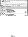
- a method of registering a device control script prepared by the user is described with reference to FIG. 9 .
- the device control script is registered and listed in the Registered control scripts field in the bottom of the window.
- a device is registered by the web browser displaying the TMNetWebConfig utility as shown in FIG. 10 .
- FIG. 17 The basic sequence of programming in Device XML is shown in FIG. 17 .
- Device Control indicates the device control function (device service interface 501), and Device denotes a controlled device.
- the interface shown in FIG. 18 is used to control devices using Device XML.
- each data item is as shown in FIG. 19A, and FIG. 19B shows a description of each data item.
- FIG. 20A and FIG. 20B Examples of communication data between the application 31 and the device service interface 501 are shown in FIG. 20A and FIG. 20B .
- the NULL character is represented by " ⁇ 0".
- FIG. 20A and FIG. 20B show examples of communication data when establishing a connection, acquiring administrator information, opening a device, controlling a device, and closing a device.
- Message data for each device specifies the data that controls the device in a sub-element of the ⁇ data> element of a ⁇ device_data> message.
- the component elements of the message data differ according to the device type.
- This message returns to the application that a connection was established.
- the application 31 sends a message described below triggered by receiving this message.
- the information is set with the TMNet WebConfig utility.
- This message is contained in a [Request].
- This message requests administrator information from the printer 5.
- This message returns the administrator information to the application 31.
- a description of the sub-elements and data types is shown in FIG. 24A .
- FIG. 24B shows the code elements.
- FIG. 24C shows the data elements.
- FIG. 24E shows examples of normal and error responses.
- This message makes the device linked to the device ID usable. Exclusive use of the specified device is given to the requesting application 31.
- This message is contained in a [Request].
- This message specifies the device to open.
- a description of the sub-elements and data types is shown in FIG. 25A .
- FIG. 25B shows the data elements.
- FIG. 25C shows an example of a request.
- This message returns the device open result to the application 31.
- a description of the sub-elements and data types is shown in FIG. 25D .
- FIG. 25E shows the code elements.
- FIG. 25F shows examples of normal and error responses.
- This message closes an opened device.
- This message is contained in a [Request].
- This message specifies the device to close.
- a description of the sub-elements and data types is shown in FIG. 26A .
- FIG. 26B shows an example of a request.
- This message returns the device close result to the application 31.
- a description of the sub-elements and data types is shown in FIG. 26C .
- FIG. 26D shows the code elements.
- FIG. 26E shows examples of normal and error responses.
- This message is contained in a [Request].
- This message sends data to a device.
- Device control commands, and print and display data are included.
- a description of the sub-elements and data types is shown in FIG. 27A .
- FIG. 27B shows an example of a request.
- This message returns data from the device.
- the result of device control, events that occurred in the device, and input data from the device are included.
- a description of the sub-elements and data types is shown in FIG. 27C .
- FIG. 27D shows an example of a response.
- This message returns device control command and service control command errors, and other common errors.
- a description of the sub-elements and data types is shown in FIG. 28A .
- FIG. 28B shows the code elements.
- FIG. 28C shows an example of a response.
- This message returns scanned data from the barcode scanner to the application.
- a description of the sub-elements and data types is shown in FIG. 29A .
- FIG. 29C shows an example of a response.
- Print data is described below in Printer Control XML.
- This message is contained in a [Request].
- This message sends print data and settings data to the printer.
- a description of the sub-elements and data types is shown in FIG. 30A .
- FIG. 30B shows an example of a request.
- This message returns the print result to the application.
- a description of the sub-elements and data types is shown in FIG. 31A .
- FIG. 31B shows an example of a response.
- Printer Control XML which is an XML document that controls a printer, is described next.
- Message data for a printer is described below under Message Data for Printers.
- This attribute declares the epos-print name.
- FIG. 32A shows the sub-elements.
- FIG. 32B shows a sample XML document.
- FIG. 33A shows the attribute values.
- FIG. 32B shows the attribute values.
- This attribute gets an OR function as a decimal expression according to the printer status.
- FIG. 32C shows the attribute values.
- FIG. 33D shows a sample XML document.
- This message specifies the character string to print. This message also configures string-related settings such as style, print position, and line feed space.
- Horizontal tab, line feed, and other symbols required for printer control are written using the entity references shown in FIG. 34A .
- FIG. 34B shows the attribute values.
- the printable character codes depend upon the specifications of the printer.
- FIG. 34C shows the attribute values.
- This attribute specifies smoothing. Text printing quality improves if smoothing is enabled.
- FIG. 34D shows the attribute values.
- FIG. 34E shows the attribute values.
- the horizontal scale specified by the width attribute takes precedence.
- FIG. 34F shows the attribute values.
- the vertical scale specified by the height attribute takes precedence.
- FIG. 34G shows the attribute values.
- the horizontal scale specified by the width attribute takes precedence.
- FIG. 34H shows the attribute values.
- the vertical scale specified by the height attribute takes precedence.
- FIG. 34I shows the attribute values.
- FIG. 34J shows the attribute values.
- FIG. 34K shows the attribute values.
- FIG. 34L shows the attribute values.
- This attribute specifies the print start position of the characters in dots.
- FIG. 34M shows the attribute values.
- the align attribute controls where the line starts.
- the align attribute set in this element also applies to the align attribute of image, logo, barcode, and symbol elements.
- FIG. 34N shows the attribute values.
- the rotate attribute is ignored in page mode.
- the print direction is set to right to left (right_to_left) using the direction element to print text rotated 180 degrees.
- the rotate attribute set in this element also applies to the rotate attribute of the barcode and symbol elements.
- This attribute specifies the paper feed distance for one line in dots.
- FIG. 34P shows an example of settings for printing a string.
- This message specifies the paper feed distance. This message specifies the paper feed distance in dots or in lines. When the paper feed amount is not specified, the paper is fed one line (line feed). This message also sets the paper feed distance per line.
- This attribute specifies the paper feed distance in dots.
- This attribute specifies the paper feed distance in lines.
- This attribute specifies the paper feed distance per line in dots.
- the paper feed distance is stored separately for the standard mode and the page mode. Specifying the linespc attribute also affects the linespc attributes of the ⁇ text> and ⁇ feed> elements that follow.
- FIG. 35 shows a sample XML document.
- This message specifies raster bit image data. (Data type xs:base64Binary)
- Raster graphics refer to data generated by horizontally scanning the pixels of an image starting from an origin at the top left corner of the image.
- Data is generated at 1 bit per pixel for two-tone images, and 4 bits per pixel for 16-tone images, starting from the most-significant bit of each byte. Zero padding is added so that scan data is in byte units for each line.
- raster images are printed from the current print position referenced to the bottom left dot of the raster image.
- the print position does not move.
- This attribute specifies the image width in dots.
- This attribute specifies the image height in dots.
- FIG. 36A shows the attribute values.
- FIG. 36B shows the attribute values.
- the align attribute set in this element also applies to the align attribute in the text, logo, barcode, and symbol elements.
- FIG. 36C shows the attribute values.
- FIG. 36D shows a sample XML document.
- This message specifies a logo registered in the NV memory of the printer.
- a logo must first be registered in the printer using a model-specific utility or logo registration utility (TMFLogo).
- TMFLogo model-specific utility or logo registration utility
- logos are printed from the current print position referenced to the bottom left dot of the logo.
- This attribute specifies the value of key code 1 set at the time of NV logo registration.
- This attribute specifies the value of key code 2 set at the time of NV logo registration. This attribute is required.
- FIG. 37A shows the attribute values.
- the align attribute set in this element also applies to the align attribute in the text, logo, barcode, and symbol elements.
- FIG. 37B shows a sample XML document.
- This message specifies barcode data as a character string.
- a barcode will not be printed if the settings are not compliant with the barcode standard, or if the barcode will be larger than the print area of the printer.
- a barcode is printed from the current print position referenced to the bottom left dot of the barcode (not including the HRI).
- FIG. 38A , FIG. 38B , and FIG. 38C show barcode types that can be specified.
- FIG. 38D shows the escape sequences used to specify binary data that cannot be represented by a character string.
- This attribute specifies the barcode type.
- FIG. 38E shows the attribute values.
- This attribute specifies the HRI position.
- FIG. 38F shows the attribute values.
- This attribute specifies the HRI font.
- FIG. 38G shows the attribute values.
- This attribute specifies the module width in dots. Specify an integer from 2 to 6.
- FIG. 38H shows the attribute values.
- the align attribute set in this element also applies to the align attribute in the text, image, logo, and symbol elements.
- FIG. 38I shows the attribute values.
- the rotate attribute set in this element also applies to the rotate attribute in the text and symbol elements.
- FIG. 38J shows a sample XML document.
- This message prints a two-dimensional symbol.
- This message specifies the two-dimensional symbol as a character string.
- a two-dimensional symbol will not be printed if the settings are not compliant with the two-dimensional symbol standard, or if the two-dimensional symbol will be larger than the print area of the printer.
- a two-dimensional symbol is printed from the current print position referenced to the bottom left dot of the two-dimensional symbol.
- FIG. 39A and FIG. 39B show two-dimensional symbol types that can be specified.
- FIG. 39C shows the escape sequences used to specify binary data that cannot be represented by a character string.
- FIG. 39D shows the attribute values.
- FIG. 39E shows the attribute values.
- the error correction level is selected according to the type of two-dimensional symbol.
- FIG. 39F shows a description.
- FIG. 39G shows a description.
- FIG. 39H shows a description.
- FIG. 39I shows the attribute values.
- the align attribute set in this element also applies to the align attribute in the text, image, logo, and barcode elements.
- FIG. 39J shows the attribute values.
- the rotate attribute set in this element also applies to the rotate attribute in the text and barcode elements.
- FIG. 39K shows a sample XML document.
- This message specifies a horizontal line.
- This attribute specifies the start position of the horizontal line (in dots).
- This attribute specifies the end position of the horizontal line (in dots).
- FIG. 40A shows the attribute values.
- FIG. 40B shows a sample XML document.
- This message starts drawing a vertical line.
- a vertical line is drawn until the end is specified by the ⁇ vline-end> message described below. This element is used with vline-end.
- This attribute specifies the start position of the vertical line (in dots).
- FIG. 41A shows sample attributes.
- FIG. 41B shows a sample XML document.
- This message stops drawing a vertical line.
- This element is used with vline-begin described above.
- This attribute specifies the end position of the vertical line (in dots).
- FIG. 42A shows sample attributes.
- FIG. 42B shows a sample XML document.
- This message changes from the standard mode to the page mode.
- FIG. 43A The elements shown in FIG. 43A can be used in ⁇ page>.
- FIG. 43B shows a sample XML document.
- This message specifies the print area in page mode.
- the print area is set by specifying the origin, width, and height referenced to the absolute origin.
- the absolute origin is a dot above the top left corner of the printable area.
- This element is used in a page element.
- This attribute specifies the origin on the horizontal axis in dots.
- This attribute specifies the origin on the vertical axis in dots.
- This attribute specifies the width of the print area in dots.
- This attribute specifies the height of the print area in dots.
- the print data may not be completely printed.
- FIG. 44B shows a sample XML document.
- This message specifies the print direction in page mode.
- This message specifies the print direction and rotates the print area.
- the starting point of the print area moves according to the rotation of the print area.
- This element is used in a page element.
- FIG. 45A shows the attribute values.
- FIG. 45B shows a sample XML document.
- This message specifies the print position in page mode.
- This message specifies the print position referenced to the starting point of the print area.
- the starting point of the print area moves according to the direction of rotation.
- This element is used in a page element.
- This attribute specifies the horizontal position in dots.
- This attribute specifies the vertical position in dots.
- This message specifies the print start position (coordinates) according to the content to be printed. Refer to the following.
- FIG. 46 shows a sample XML document.
- This message draws a straight line in page mode.
- This element is used in a page element.
- This attribute specifies the position (in dots) to start printing a horizontal line.
- This attribute specifies the position (in dots) to start printing a vertical line.
- This attribute specifies the position (in dots) to stop printing a horizontal line.
- This attribute specifies the position (in dots) to stop printing a vertical line. Specify the line type.
- FIG. 47A shows the attribute values.
- FIG. 47B shows a sample XML document.
- This message draws a rectangle in page mode.
- This element is used in a page element.
- This attribute specifies the position (in dots) to start printing a horizontal line.
- This attribute specifies the position (in dots) to start printing a vertical line.
- This attribute specifies the position (in dots) to stop printing a horizontal line.
- This attribute specifies the position (in dots) to stop printing a vertical line. Specify the line type.
- FIG. 48A shows examples of attributes.
- FIG. 48B shows a sample XML document.
- This message specifies a paper cut.
- This message is used in standard mode.
- This message executes at the beginning of a line.
- the paper is at the beginning of a line after the paper is cut.
- FIG. 49A shows examples of attributes.
- FIG. 49B shows a sample XML document.
- This message specifies outputting a signal to the drawer kick-out connector.
- a buzzer can be sounded depending upon the model.
- FIG. 50A shows the attribute values.
- FIG. 50B shows the attribute values.
- FIG. shows a sample XML document.
- This message sounds a buzzer.
- FIG. 51A shows the attribute values.
- FIG. 51B shows the attribute values.
- FIG. shows a sample XML document.
- FIG. 52A shows sub-elements.
- FIG. 52B shows an example of a request.
- FIG. 53A shows the sub-element.
- FIG. 53B shows an example of a response.
- Customer Display Control XML which is an XML document that controls a customer display, is described next.
- Message data for a customer display is described above under Message Data for the Customer Display.
- An ⁇ epos-display> message contains sub-elements required to control the customer display.
- FIG. 54A shows sub-elements.
- FIG. 54B shows a sample XML document.
- FIG. 55A shows the attribute values.
- FIG. 55B shows the attribute values.
- This attribute is always set to 0.
- FIG. 55C shows a sample XML document.
- This message controls creating and deleting windows and moving the current window.
- This attribute specifies the number of the target window.
- FIG. 56 shows the attribute values.
- This attribute specifies the x-coordinate (1 to 20) as an integer to create a window.
- This attribute specifies the y-coordinate (1 or 2) as an integer to create a window.
- This attribute specifies the width (1 to 20) as an integer to create a window.
- This attribute specifies the height (1 or 2) as an integer to create a window.
- This attribute specifies the scrolling method of the window when a window is created.
- FIG. 57A shows the attribute values.
- This attribute specifies whether or not to delete the window specified by the number attribute.
- FIG. 57B shows the attribute values.
- FIG. 57D shows a sample XML document.
- This message controls displaying a character string.
- This attribute specifies the x-coordinate (1 to 20) of the text display as an integer.
- This attribute specifies the y-coordinate (1 or 2) of the text display as an integer.
- FIG. 58A shows the attribute values.
- This attribute specifies the language of the text display. If omitted, the current setting is used.
- FIG. 58B shows the attribute values.
- FIG. 58C shows a sample XML document.
- This message controls the cursor position and display settings.
- This attribute specifies the x-coordinate (1 to 20) of the cursor as an integer.
- This attribute specifies the y-coordinate (1 or 2) of the cursor as an integer.
- This attribute specifies the cursor position in the current window.
- FIG. 59A shows the attribute values.
- This attribute specifies the display method of the cursor. If omitted, the current setting is used.
- FIG. 59B shows the attribute values.
- FIG. 59C shows a sample XML document.
- This message controls screen blinking. Blinking continues at the interval specified in the interval attribute.
- the actual blinking interval is rounded up in 50 ms increments.
- interval is 1 to 50
- the actual interval is 50 ms
- the actual interval is 100 ms.
- This attribute specifies the blinking interval as an integer.
- FIG. 60A shows the attribute values.
- FIG. 60B shows a sample XML document.
- This message controls the display brightness.
- This attribute specifies brightness as a percentage.
- FIG. 61A shows the attribute values.
- FIG. 61B shows a sample XML document.
- This message controls the marquee display of a character string.
- the specified string is displayed 1 character at a time at the interval specified in uwait. After the string is displayed to the end, display pauses for the time specified by rwait, and the string is then displayed again from the beginning.
- This attribute specifies the display pattern for the marquee.
- FIG. 62A shows the attribute values.
- FIG. 62B shows the attribute values.
- This attribute specifies the interval waited to display each character in milliseconds.
- FIG. 62C shows the attribute values.
- FIG. 62D shows the attribute values.
- This attribute specifies display language. If omitted, the current setting is used.
- FIG. 62E shows the attribute values.
- FIG. 62F shows a sample XML document.
- This message displays the time in the bottom right corner of the display.
- the displayed time is the local time managed by the OS of the printer 5.
- FIG. 63 shows a sample XML document.
- This message clears the display of the current window.
- FIG. 64 shows a sample XML document.
- FIG. 65 shows a sample XML document.
- This message executes a desired ESC/POS command.
- the desired command is specified by a hexadecimal string.
- FIG. 66 shows a sample XML document.
- FIG. 67A shows sub-elements.
- FIG. 67C shows an example of a response.
- This message specifies the key code used to determine the start of a character string to detect input from the POS keyboard. If a key code specified by this message is input, the character string from then until the Enter key is pressed is returned in the onstring message. This is used, for example, to substitute input from the POS keyboard for barcode input. To stop the onstring message, send a setprefix message without a keycode.
- This message specifies the key code used to determine the start of a character string to detect input from the POS keyboard.
- FIG. 68A shows sub-elements.
- FIG. 68B shows an example of a request.
- This message returns input data from the POS keyboard to the application.
- This message reports detection of input from any one of the key codes specified with setprefix to Enter.
- the detected key code information is acquired in the argument in addition to the input sequence of characters.
- FIG. 69A shows sub-elements.
- FIG. 69C shows an example of a response.
- FIG. 70A shows sub-elements.
- FIG. 70B shows an example of a request.
- FIG. 71A shows sub-elements.
- FIG. 71B shows the attribute values.
- FIG. 71C shows an example of a response.
- the device control script 502 is described next.
- FIG. 72 describes using a device control script.
- a device control script 502 has a DeviceConnection object 503 and a ClientConnection object 504.
- devices of the highly functional printer 5 are collectively represented by device 20.
- the socket interface 500 of the printer 5 receives the XML data.
- the socket interface 500 then passes the received data to the device service interface 501.
- the device service interface 501 then instantiates an object so that the device control script corresponding to the device requested by the open_device message can be used.
- the device 20 can then be controlled through the instantiated object.
- the objects shown in FIG. 73 are then passed to the device control script 502 from the device service interface 501.
- the device connection (DeviceConnection) object 503 and client connection (ClientConnection) object 504 the device control script 502 can communicate with the application 31 and device 20.
- a device control script is coded to include the following conditions.
- a list of settings is shown in FIG. 74 .
- a list of settings is shown in FIG. 75 .
- FIG. 76 shows an example of the configuration of a sample device control script 502.
- the ClientConnection object is described next.
- This object is an object passed to the first parameter of the constructor of the device control script 502.
- This method sends data to a device object that runs on a browser.
- This parameter specifies the event name of the device object.
- This parameter specifies the data passed to the device object event.
- FIG. 80 An example is shown in FIG. 80 .
- the onkeypress event of the device object is called, and 49 is received from data.keycode and 1 is received from data.ascii using the data parameter of the onkeypress event.
- the DeviceConnection object is described next.
- This object is an object passed in the second parameter of the constructor of the device control script 502.
- This method sends data to a serial communication device.
- This parameter specifies the data to send to the device.
- the device control script Name object is described next.
- This event receives detected data from a key input device.
- This parameter receives the direction of key operation. For a list of values, see FIG. 81 .
- This parameter receives the key code.
- key codes see FIG. 3A and FIG. 3B .
- This parameter receives the character corresponding to the operated key.
- This event receives data detected from a serial communication device.
- This parameter receives data received from a serial communication device.
- This event receives the results of API execution by a device object that runs on a browser.
- This parameter receives the object specified by the callEvent parameter of the device object.
- this program provides the ability to read data with the barcode scanner and print.
- FIG. 83A The work flow for building the program environment is shown in FIG. 83A .
- Registration is done from a web browser.
- the barcode scanner 9 is registered and configured using the TMNet WebConfig utility.
- FIG. 94A shows an example of the TMNet WebConfig screen.
- a device control system 100 has a terminal 3 that executes an application 31, and a printer 5 with a connection panel 60 to which a device connects, connected over a network.
- the terminal 3 sends XML data generated by the application 31 to the printer 5.
- the printer 5 receives the XML data sent from the terminal 3 through a socket interface 500.
- the printer 5 sends the administrator information of the printer 5 to the terminal 3 using functions of a device service interface 501 and device control script 502.
- the printer 5 controls the device.
- devices connected to the printer 5 can be controlled by a terminal 3 connected to the network.
- the terminal 3 can be any device that can run an application that generates data written in XML. Because XML is highly versatile, many different devices can be used as the terminal 3. Developing applications for the terminal 3 is also simple.
- the printer 5 When the terminal 3 requests administrator information by sending data containing an ⁇ admin_info> message, the printer 5 returns XML data including the administrator name and/or location stored by the printer 5 to the terminal 3.
- the printer 5 When the terminal 3 sends data including a device open request, the printer 5 enables controlling the device, and when the terminal 3 sends data including a device close request, the printer 5 disables control of the controlled device.
- the data generated by the application 31 also includes message data that differs for each device connected to the printer 5, or message data common to devices.
- the printer 5 When controlling a device requested by data, the printer 5 also instantiates a DeviceConnection object that sends data to the device, and a ClientConnection object that sends data to the terminal 3.
- the present invention is useful in a device control system that controls devices, and can be applied to controlling devices and printers used in a POS system.
Landscapes
- Engineering & Computer Science (AREA)
- Theoretical Computer Science (AREA)
- Physics & Mathematics (AREA)
- General Physics & Mathematics (AREA)
- General Engineering & Computer Science (AREA)
- Human Computer Interaction (AREA)
- Business, Economics & Management (AREA)
- Accounting & Taxation (AREA)
- Computer Networks & Wireless Communication (AREA)
- General Business, Economics & Management (AREA)
- Strategic Management (AREA)
- Finance (AREA)
- Multimedia (AREA)
- Signal Processing (AREA)
- Accessory Devices And Overall Control Thereof (AREA)
- Computer And Data Communications (AREA)
- Information Transfer Between Computers (AREA)
- Telephonic Communication Services (AREA)
- User Interface Of Digital Computer (AREA)
- Selective Calling Equipment (AREA)
- Facsimiles In General (AREA)
Applications Claiming Priority (2)
| Application Number | Priority Date | Filing Date | Title |
|---|---|---|---|
| US201361748232P | 2013-01-02 | 2013-01-02 | |
| PCT/JP2013/007633 WO2014106883A1 (ja) | 2013-01-02 | 2013-12-26 | デバイス制御システム、及び、デバイス制御システムの制御方法 |
Publications (3)
| Publication Number | Publication Date |
|---|---|
| EP2800000A1 EP2800000A1 (en) | 2014-11-05 |
| EP2800000A4 EP2800000A4 (en) | 2015-11-04 |
| EP2800000B1 true EP2800000B1 (en) | 2020-08-26 |
Family
ID=51016898
Family Applications (2)
| Application Number | Title | Priority Date | Filing Date |
|---|---|---|---|
| EP13870266.7A Active EP2800000B1 (en) | 2013-01-02 | 2013-12-26 | Device control system and method for controlling device control system |
| EP13870202.2A Active EP2799999B1 (en) | 2013-01-02 | 2013-12-26 | Device control system and method for controlling device control system |
Family Applications After (1)
| Application Number | Title | Priority Date | Filing Date |
|---|---|---|---|
| EP13870202.2A Active EP2799999B1 (en) | 2013-01-02 | 2013-12-26 | Device control system and method for controlling device control system |
Country Status (7)
| Country | Link |
|---|---|
| US (7) | US9280305B2 (zh) |
| EP (2) | EP2800000B1 (zh) |
| JP (2) | JP6206417B2 (zh) |
| KR (3) | KR101736017B1 (zh) |
| CN (2) | CN104412244B (zh) |
| IN (2) | IN2014DN06744A (zh) |
| WO (2) | WO2014106882A1 (zh) |
Families Citing this family (21)
| Publication number | Priority date | Publication date | Assignee | Title |
|---|---|---|---|---|
| KR101632221B1 (ko) * | 2014-02-27 | 2016-07-01 | 엘지전자 주식회사 | 디지털 디바이스 및 그의 서비스 처리 방법 |
| JP5958490B2 (ja) * | 2014-03-31 | 2016-08-02 | コニカミノルタ株式会社 | ウェブシステム、ウェブサーバ、データ配信方法、およびコンピュータプログラム |
| CN109324768B (zh) * | 2014-12-30 | 2021-10-22 | 珠海奔图电子有限公司 | 一种通过移动终端将用户帐号与图像形成设备绑定的方法及系统 |
| WO2017086989A1 (en) * | 2015-11-20 | 2017-05-26 | Hewlett-Packard Development Company, L.P. | Xml file condensing |
| US9509942B1 (en) | 2016-02-08 | 2016-11-29 | Picaboo Corporation | Automatic content categorizing system and method |
| CN106970767A (zh) * | 2017-03-03 | 2017-07-21 | 华中科技大学 | 一种实现本地打印机接入云打印平台的方法和系统 |
| US11752779B2 (en) | 2017-12-12 | 2023-09-12 | Gpcp Ip Holdings Llc | Food service cup dispensers, systems, and methods |
| US20190180392A1 (en) | 2017-12-12 | 2019-06-13 | Gpcp Ip Holdings Llc | Personalized food service material printing systems |
| US11472579B2 (en) | 2018-12-04 | 2022-10-18 | Gpcp Ip Holdings Llc | Film securing apparatus and method |
| CN108773205B (zh) * | 2018-06-13 | 2024-04-05 | 马方立 | 智能打印装置及智能打印控制方法 |
| CN108898002B (zh) * | 2018-07-06 | 2021-10-08 | 青岛山景虚拟现实研究院 | 一种可与计算机无线连接的扫描枪装置 |
| JP7320822B2 (ja) * | 2018-08-22 | 2023-08-04 | 株式会社アスタリスク | システム及び周辺装置 |
| CN110969032B (zh) * | 2018-09-28 | 2023-09-05 | 捷普电子(广州)有限公司 | 用于扫描物体的扫描设备 |
| JP7135685B2 (ja) * | 2018-09-28 | 2022-09-13 | 株式会社リコー | 電子機器、情報処理システム及び終了操作抑制方法 |
| JP7278805B2 (ja) * | 2019-03-04 | 2023-05-22 | キヤノン株式会社 | 情報処理装置、情報処理装置の制御方法及びプログラム |
| JP2020204950A (ja) * | 2019-06-18 | 2020-12-24 | コニカミノルタ株式会社 | 情報処理システム、情報処理システムの制御方法、装置、及び制御プログラム |
| JP7234849B2 (ja) * | 2019-08-05 | 2023-03-08 | 富士通株式会社 | 情報処理装置、アクセス制御システム及びアクセス制御プログラム |
| JP6732092B1 (ja) * | 2019-12-12 | 2020-07-29 | シチズン時計株式会社 | 機器制御方法、機器制御プログラム、および機器制御装置 |
| RU2758816C1 (ru) * | 2020-06-29 | 2021-11-02 | Георгий Ревазович Хвистани | Система и способ фотофиксации заказов предприятия общественного питания |
| JP2022138292A (ja) | 2021-03-10 | 2022-09-26 | セイコーエプソン株式会社 | 情報処理装置及びシステム |
| JP2022138291A (ja) | 2021-03-10 | 2022-09-26 | セイコーエプソン株式会社 | システム、サーバー装置及び端末装置 |
Citations (1)
| Publication number | Priority date | Publication date | Assignee | Title |
|---|---|---|---|---|
| US20050046887A1 (en) * | 2003-09-01 | 2005-03-03 | Konica Minolta Business Technologies, Inc. | Image processing apparatus for receiving a request relating to image processing from an external source and executing the received request |
Family Cites Families (42)
| Publication number | Priority date | Publication date | Assignee | Title |
|---|---|---|---|---|
| JP3399051B2 (ja) | 1993-11-24 | 2003-04-21 | セイコーエプソン株式会社 | Posターミナル及びその印刷装置 |
| US5707162A (en) | 1993-11-24 | 1998-01-13 | Seiko Epson Corporation | Modular information processing apparatus |
| US20010021669A1 (en) | 1995-11-20 | 2001-09-13 | Creator Ltd. | I*doll |
| US5752880A (en) | 1995-11-20 | 1998-05-19 | Creator Ltd. | Interactive doll |
| US6368177B1 (en) | 1995-11-20 | 2002-04-09 | Creator, Ltd. | Method for using a toy to conduct sales over a network |
| US6128415A (en) * | 1996-09-06 | 2000-10-03 | Polaroid Corporation | Device profiles for use in a digital image processing system |
| US6519048B1 (en) | 1998-04-28 | 2003-02-11 | Canon Kabushiki Kaisha | Image forming apparatus, image forming method, and storage medium storing computer readable program therein |
| US6289371B1 (en) | 1998-09-30 | 2001-09-11 | Hewlett-Packard Company | Network scan server support method using a web browser |
| WO2002037291A1 (fr) * | 2000-10-26 | 2002-05-10 | Matsushita Electric Industrial Co., Ltd. | Dispositif de designation d"image objet d"impression |
| JP2002176675A (ja) * | 2000-12-06 | 2002-06-21 | Seiko Epson Corp | データ伝送システム及びその方法 |
| US20020097417A1 (en) | 2001-01-19 | 2002-07-25 | Chang William Ho | System for universal data output |
| JP3802829B2 (ja) * | 2002-03-14 | 2006-07-26 | 株式会社リコー | 画像情報処理装置、リモート画像情報処理方法およびその方法をコンピュータに実行させるプログラム |
| JP2003288336A (ja) | 2002-03-28 | 2003-10-10 | Brother Ind Ltd | 特定機能代行システム、及び、電子機器、記憶媒体 |
| JP4341326B2 (ja) | 2002-09-05 | 2009-10-07 | セイコーエプソン株式会社 | 印刷方法、印刷装置、プリンタドライバ、商品販売データ処理装置およびposシステム |
| CN1287334C (zh) | 2002-09-05 | 2006-11-29 | 精工爱普生株式会社 | 打印方法、程序及装置、商品销售数据处理装置、pos系统 |
| JP2006135982A (ja) | 2003-04-24 | 2006-05-25 | Mitsubishi Electric Corp | ネットワーク接続装置、映像情報機器、情報送受信機器、及びネットワーク接続プログラム |
| WO2004095293A1 (ja) | 2003-04-24 | 2004-11-04 | Mitsubishi Denki Kabushiki Kaisha | 映像機器、映像モジュールユニット及び映像機器操作方法 |
| CN101136836A (zh) * | 2003-04-24 | 2008-03-05 | 三菱电机株式会社 | 影像设备,影像模块单元以及影像设备操作方法 |
| KR100538903B1 (ko) | 2003-06-24 | 2005-12-27 | 삼성전자주식회사 | 네트워크 인터페이스 장치 |
| JP2005045437A (ja) * | 2003-07-25 | 2005-02-17 | Fuji Xerox Co Ltd | スキャナシステムおよびその方法 |
| JP2006344173A (ja) * | 2005-06-10 | 2006-12-21 | Canon Inc | 情報処理装置及びその制御方法 |
| JP4742766B2 (ja) | 2005-09-14 | 2011-08-10 | 富士ゼロックス株式会社 | ネットワークデバイス、デバイスリンクシステムおよびデバイスリンク方法 |
| JP5013742B2 (ja) | 2005-12-15 | 2012-08-29 | 株式会社リコー | 通信装置、情報処理システム、アプリケーション実行方法、アプリケーション実行プログラム及び記録媒体 |
| US20100153225A1 (en) * | 2006-03-26 | 2010-06-17 | Jay Ferro | Printing Dynamic Image Content on Receipts |
| US7658323B2 (en) | 2006-05-24 | 2010-02-09 | Sun Microsystems, Inc. | Point-of-service (POS) and POS application compatability |
| JP2007328558A (ja) | 2006-06-08 | 2007-12-20 | Ricoh Co Ltd | データ処理装置、データ処理システム、データ処理装置の制御方法、データ変換機能付加方法、プログラム及び記録媒体 |
| JP4066383B2 (ja) * | 2006-07-06 | 2008-03-26 | シチズンホールディングス株式会社 | 通信装置および通信制御方法、並びに当該通信装置を備えたプリンタ |
| JP4269182B2 (ja) * | 2006-10-18 | 2009-05-27 | セイコーエプソン株式会社 | 印刷測色制御装置、印刷測色制御方法、印刷測色制御プログラムおよび印刷装置 |
| EP2083404A3 (en) * | 2008-01-24 | 2010-01-06 | Seiko Epson Corporation | Receipt printing processing method, printer and receipt printing processing system |
| JP4473325B2 (ja) * | 2008-05-23 | 2010-06-02 | 富士通株式会社 | 管理装置、ストレージシステム、記憶装置管理方法 |
| JP4777387B2 (ja) * | 2008-06-05 | 2011-09-21 | 株式会社東芝 | スクリプト秘匿実行プログラム及びサーバ装置 |
| JP5272897B2 (ja) * | 2008-07-29 | 2013-08-28 | セイコーエプソン株式会社 | 印刷装置、印刷装置の制御方法及び制御プログラム |
| JP4645723B2 (ja) * | 2008-10-08 | 2011-03-09 | ブラザー工業株式会社 | 通信装置 |
| JP5440004B2 (ja) | 2008-10-20 | 2014-03-12 | セイコーエプソン株式会社 | 情報配信システム、情報配信システムのサービス実現方法およびそのプログラム |
| JP5124779B2 (ja) * | 2008-11-07 | 2013-01-23 | キヤノンイメージングシステムズ株式会社 | デバイス共有システム、デバイス共有クライアント、及びデバイス共有方法 |
| US8643875B2 (en) | 2009-01-09 | 2014-02-04 | Transaction Tree, Inc. | Receipt handling systems, print drivers and methods thereof |
| JP5305999B2 (ja) * | 2009-03-16 | 2013-10-02 | キヤノン株式会社 | 情報処理装置、その制御方法、及びプログラム |
| JP5451355B2 (ja) * | 2009-12-14 | 2014-03-26 | シャープ株式会社 | 情報機器、画像処理装置、情報機器と通信可能な情報処理装置およびそれらを含む情報処理システム |
| US8610927B2 (en) * | 2010-02-09 | 2013-12-17 | Apple Inc. | Walk-up printing without drivers |
| US20110231272A1 (en) * | 2010-03-16 | 2011-09-22 | App Masters Llc | Retail mobile point-of-sale (POS) software application and retail middleware software application |
| JP5732896B2 (ja) | 2011-02-21 | 2015-06-10 | セイコーエプソン株式会社 | ネットワークシステムおよびネットワークシステムの制御方法 |
| US8700474B2 (en) * | 2012-08-27 | 2014-04-15 | Wal-Mart Stores, Inc. | Deliverying customer specified receipt types at checkout |
-
2013
- 2013-12-24 US US14/140,301 patent/US9280305B2/en active Active
- 2013-12-24 US US14/140,268 patent/US9052853B2/en active Active
- 2013-12-26 KR KR1020167022773A patent/KR101736017B1/ko active IP Right Grant
- 2013-12-26 CN CN201380035523.3A patent/CN104412244B/zh active Active
- 2013-12-26 WO PCT/JP2013/007625 patent/WO2014106882A1/ja active Application Filing
- 2013-12-26 CN CN201380035049.4A patent/CN104583984B/zh active Active
- 2013-12-26 JP JP2014555400A patent/JP6206417B2/ja active Active
- 2013-12-26 WO PCT/JP2013/007633 patent/WO2014106883A1/ja active Application Filing
- 2013-12-26 JP JP2014555399A patent/JP6277961B2/ja active Active
- 2013-12-26 IN IN6744DEN2014 patent/IN2014DN06744A/en unknown
- 2013-12-26 EP EP13870266.7A patent/EP2800000B1/en active Active
- 2013-12-26 IN IN6745DEN2014 patent/IN2014DN06745A/en unknown
- 2013-12-26 KR KR1020157019455A patent/KR101645148B1/ko active IP Right Grant
- 2013-12-26 EP EP13870202.2A patent/EP2799999B1/en active Active
- 2013-12-26 KR KR1020157019487A patent/KR101652655B1/ko active IP Right Grant
-
2015
- 2015-05-01 US US14/702,362 patent/US9274730B2/en active Active
- 2015-12-22 US US14/979,291 patent/US10108949B2/en active Active
- 2015-12-30 US US14/984,029 patent/US9495121B2/en active Active
-
2016
- 2016-09-19 US US15/269,172 patent/US10043169B2/en active Active
-
2018
- 2018-06-27 US US16/020,450 patent/US10402809B2/en active Active
Patent Citations (1)
| Publication number | Priority date | Publication date | Assignee | Title |
|---|---|---|---|---|
| US20050046887A1 (en) * | 2003-09-01 | 2005-03-03 | Konica Minolta Business Technologies, Inc. | Image processing apparatus for receiving a request relating to image processing from an external source and executing the received request |
Also Published As
Similar Documents
| Publication | Publication Date | Title |
|---|---|---|
| EP2800000B1 (en) | Device control system and method for controlling device control system | |
| US10089560B2 (en) | ePOS printing |
Legal Events
| Date | Code | Title | Description |
|---|---|---|---|
| PUAI | Public reference made under article 153(3) epc to a published international application that has entered the european phase |
Free format text: ORIGINAL CODE: 0009012 |
|
| 17P | Request for examination filed |
Effective date: 20140730 |
|
| AK | Designated contracting states |
Kind code of ref document: A1 Designated state(s): AL AT BE BG CH CY CZ DE DK EE ES FI FR GB GR HR HU IE IS IT LI LT LU LV MC MK MT NL NO PL PT RO RS SE SI SK SM TR |
|
| RA4 | Supplementary search report drawn up and despatched (corrected) |
Effective date: 20151005 |
|
| RIC1 | Information provided on ipc code assigned before grant |
Ipc: G06F 3/12 20060101ALI20150929BHEP Ipc: G06F 13/00 20060101AFI20150929BHEP |
|
| DAX | Request for extension of the european patent (deleted) | ||
| STAA | Information on the status of an ep patent application or granted ep patent |
Free format text: STATUS: EXAMINATION IS IN PROGRESS |
|
| 17Q | First examination report despatched |
Effective date: 20180917 |
|
| REG | Reference to a national code |
Ref country code: DE Ref legal event code: R079 Ref document number: 602013072043 Country of ref document: DE Free format text: PREVIOUS MAIN CLASS: G06F0013000000 Ipc: G06F0003120000 |
|
| GRAP | Despatch of communication of intention to grant a patent |
Free format text: ORIGINAL CODE: EPIDOSNIGR1 |
|
| STAA | Information on the status of an ep patent application or granted ep patent |
Free format text: STATUS: GRANT OF PATENT IS INTENDED |
|
| RIC1 | Information provided on ipc code assigned before grant |
Ipc: G07G 1/14 20060101ALI20200217BHEP Ipc: G06Q 20/20 20120101ALI20200217BHEP Ipc: H04N 1/00 20060101ALI20200217BHEP Ipc: G06F 3/12 20060101AFI20200217BHEP |
|
| INTG | Intention to grant announced |
Effective date: 20200316 |
|
| GRAS | Grant fee paid |
Free format text: ORIGINAL CODE: EPIDOSNIGR3 |
|
| GRAA | (expected) grant |
Free format text: ORIGINAL CODE: 0009210 |
|
| STAA | Information on the status of an ep patent application or granted ep patent |
Free format text: STATUS: THE PATENT HAS BEEN GRANTED |
|
| AK | Designated contracting states |
Kind code of ref document: B1 Designated state(s): AL AT BE BG CH CY CZ DE DK EE ES FI FR GB GR HR HU IE IS IT LI LT LU LV MC MK MT NL NO PL PT RO RS SE SI SK SM TR |
|
| REG | Reference to a national code |
Ref country code: GB Ref legal event code: FG4D |
|
| RIN1 | Information on inventor provided before grant (corrected) |
Inventor name: TSUTSUMI, KOICHIRO Inventor name: IKEDA, SHIGEO Inventor name: TAKASU, KAZUHIRO |
|
| REG | Reference to a national code |
Ref country code: CH Ref legal event code: EP |
|
| REG | Reference to a national code |
Ref country code: DE Ref legal event code: R096 Ref document number: 602013072043 Country of ref document: DE |
|
| REG | Reference to a national code |
Ref country code: AT Ref legal event code: REF Ref document number: 1306991 Country of ref document: AT Kind code of ref document: T Effective date: 20200915 |
|
| REG | Reference to a national code |
Ref country code: IE Ref legal event code: FG4D |
|
| REG | Reference to a national code |
Ref country code: LT Ref legal event code: MG4D |
|
| PG25 | Lapsed in a contracting state [announced via postgrant information from national office to epo] |
Ref country code: LT Free format text: LAPSE BECAUSE OF FAILURE TO SUBMIT A TRANSLATION OF THE DESCRIPTION OR TO PAY THE FEE WITHIN THE PRESCRIBED TIME-LIMIT Effective date: 20200826 Ref country code: PT Free format text: LAPSE BECAUSE OF FAILURE TO SUBMIT A TRANSLATION OF THE DESCRIPTION OR TO PAY THE FEE WITHIN THE PRESCRIBED TIME-LIMIT Effective date: 20201228 Ref country code: HR Free format text: LAPSE BECAUSE OF FAILURE TO SUBMIT A TRANSLATION OF THE DESCRIPTION OR TO PAY THE FEE WITHIN THE PRESCRIBED TIME-LIMIT Effective date: 20200826 Ref country code: NO Free format text: LAPSE BECAUSE OF FAILURE TO SUBMIT A TRANSLATION OF THE DESCRIPTION OR TO PAY THE FEE WITHIN THE PRESCRIBED TIME-LIMIT Effective date: 20201126 Ref country code: BG Free format text: LAPSE BECAUSE OF FAILURE TO SUBMIT A TRANSLATION OF THE DESCRIPTION OR TO PAY THE FEE WITHIN THE PRESCRIBED TIME-LIMIT Effective date: 20201126 Ref country code: SE Free format text: LAPSE BECAUSE OF FAILURE TO SUBMIT A TRANSLATION OF THE DESCRIPTION OR TO PAY THE FEE WITHIN THE PRESCRIBED TIME-LIMIT Effective date: 20200826 Ref country code: GR Free format text: LAPSE BECAUSE OF FAILURE TO SUBMIT A TRANSLATION OF THE DESCRIPTION OR TO PAY THE FEE WITHIN THE PRESCRIBED TIME-LIMIT Effective date: 20201127 Ref country code: FI Free format text: LAPSE BECAUSE OF FAILURE TO SUBMIT A TRANSLATION OF THE DESCRIPTION OR TO PAY THE FEE WITHIN THE PRESCRIBED TIME-LIMIT Effective date: 20200826 |
|
| REG | Reference to a national code |
Ref country code: NL Ref legal event code: MP Effective date: 20200826 |
|
| REG | Reference to a national code |
Ref country code: AT Ref legal event code: MK05 Ref document number: 1306991 Country of ref document: AT Kind code of ref document: T Effective date: 20200826 |
|
| PG25 | Lapsed in a contracting state [announced via postgrant information from national office to epo] |
Ref country code: IS Free format text: LAPSE BECAUSE OF FAILURE TO SUBMIT A TRANSLATION OF THE DESCRIPTION OR TO PAY THE FEE WITHIN THE PRESCRIBED TIME-LIMIT Effective date: 20201226 Ref country code: RS Free format text: LAPSE BECAUSE OF FAILURE TO SUBMIT A TRANSLATION OF THE DESCRIPTION OR TO PAY THE FEE WITHIN THE PRESCRIBED TIME-LIMIT Effective date: 20200826 Ref country code: LV Free format text: LAPSE BECAUSE OF FAILURE TO SUBMIT A TRANSLATION OF THE DESCRIPTION OR TO PAY THE FEE WITHIN THE PRESCRIBED TIME-LIMIT Effective date: 20200826 Ref country code: NL Free format text: LAPSE BECAUSE OF FAILURE TO SUBMIT A TRANSLATION OF THE DESCRIPTION OR TO PAY THE FEE WITHIN THE PRESCRIBED TIME-LIMIT Effective date: 20200826 Ref country code: PL Free format text: LAPSE BECAUSE OF FAILURE TO SUBMIT A TRANSLATION OF THE DESCRIPTION OR TO PAY THE FEE WITHIN THE PRESCRIBED TIME-LIMIT Effective date: 20200826 |
|
| PG25 | Lapsed in a contracting state [announced via postgrant information from national office to epo] |
Ref country code: RO Free format text: LAPSE BECAUSE OF FAILURE TO SUBMIT A TRANSLATION OF THE DESCRIPTION OR TO PAY THE FEE WITHIN THE PRESCRIBED TIME-LIMIT Effective date: 20200826 Ref country code: SM Free format text: LAPSE BECAUSE OF FAILURE TO SUBMIT A TRANSLATION OF THE DESCRIPTION OR TO PAY THE FEE WITHIN THE PRESCRIBED TIME-LIMIT Effective date: 20200826 Ref country code: EE Free format text: LAPSE BECAUSE OF FAILURE TO SUBMIT A TRANSLATION OF THE DESCRIPTION OR TO PAY THE FEE WITHIN THE PRESCRIBED TIME-LIMIT Effective date: 20200826 Ref country code: DK Free format text: LAPSE BECAUSE OF FAILURE TO SUBMIT A TRANSLATION OF THE DESCRIPTION OR TO PAY THE FEE WITHIN THE PRESCRIBED TIME-LIMIT Effective date: 20200826 Ref country code: CZ Free format text: LAPSE BECAUSE OF FAILURE TO SUBMIT A TRANSLATION OF THE DESCRIPTION OR TO PAY THE FEE WITHIN THE PRESCRIBED TIME-LIMIT Effective date: 20200826 |
|
| REG | Reference to a national code |
Ref country code: DE Ref legal event code: R097 Ref document number: 602013072043 Country of ref document: DE |
|
| PG25 | Lapsed in a contracting state [announced via postgrant information from national office to epo] |
Ref country code: AL Free format text: LAPSE BECAUSE OF FAILURE TO SUBMIT A TRANSLATION OF THE DESCRIPTION OR TO PAY THE FEE WITHIN THE PRESCRIBED TIME-LIMIT Effective date: 20200826 Ref country code: AT Free format text: LAPSE BECAUSE OF FAILURE TO SUBMIT A TRANSLATION OF THE DESCRIPTION OR TO PAY THE FEE WITHIN THE PRESCRIBED TIME-LIMIT Effective date: 20200826 Ref country code: ES Free format text: LAPSE BECAUSE OF FAILURE TO SUBMIT A TRANSLATION OF THE DESCRIPTION OR TO PAY THE FEE WITHIN THE PRESCRIBED TIME-LIMIT Effective date: 20200826 |
|
| PG25 | Lapsed in a contracting state [announced via postgrant information from national office to epo] |
Ref country code: SK Free format text: LAPSE BECAUSE OF FAILURE TO SUBMIT A TRANSLATION OF THE DESCRIPTION OR TO PAY THE FEE WITHIN THE PRESCRIBED TIME-LIMIT Effective date: 20200826 |
|
| PLBE | No opposition filed within time limit |
Free format text: ORIGINAL CODE: 0009261 |
|
| STAA | Information on the status of an ep patent application or granted ep patent |
Free format text: STATUS: NO OPPOSITION FILED WITHIN TIME LIMIT |
|
| PG25 | Lapsed in a contracting state [announced via postgrant information from national office to epo] |
Ref country code: IT Free format text: LAPSE BECAUSE OF FAILURE TO SUBMIT A TRANSLATION OF THE DESCRIPTION OR TO PAY THE FEE WITHIN THE PRESCRIBED TIME-LIMIT Effective date: 20200826 |
|
| REG | Reference to a national code |
Ref country code: CH Ref legal event code: PL |
|
| 26N | No opposition filed |
Effective date: 20210527 |
|
| PG25 | Lapsed in a contracting state [announced via postgrant information from national office to epo] |
Ref country code: MC Free format text: LAPSE BECAUSE OF FAILURE TO SUBMIT A TRANSLATION OF THE DESCRIPTION OR TO PAY THE FEE WITHIN THE PRESCRIBED TIME-LIMIT Effective date: 20200826 Ref country code: SI Free format text: LAPSE BECAUSE OF FAILURE TO SUBMIT A TRANSLATION OF THE DESCRIPTION OR TO PAY THE FEE WITHIN THE PRESCRIBED TIME-LIMIT Effective date: 20200826 |
|
| REG | Reference to a national code |
Ref country code: BE Ref legal event code: MM Effective date: 20201231 |
|
| PG25 | Lapsed in a contracting state [announced via postgrant information from national office to epo] |
Ref country code: IE Free format text: LAPSE BECAUSE OF NON-PAYMENT OF DUE FEES Effective date: 20201226 Ref country code: LU Free format text: LAPSE BECAUSE OF NON-PAYMENT OF DUE FEES Effective date: 20201226 |
|
| PG25 | Lapsed in a contracting state [announced via postgrant information from national office to epo] |
Ref country code: LI Free format text: LAPSE BECAUSE OF NON-PAYMENT OF DUE FEES Effective date: 20201231 Ref country code: CH Free format text: LAPSE BECAUSE OF NON-PAYMENT OF DUE FEES Effective date: 20201231 |
|
| PG25 | Lapsed in a contracting state [announced via postgrant information from national office to epo] |
Ref country code: TR Free format text: LAPSE BECAUSE OF FAILURE TO SUBMIT A TRANSLATION OF THE DESCRIPTION OR TO PAY THE FEE WITHIN THE PRESCRIBED TIME-LIMIT Effective date: 20200826 Ref country code: MT Free format text: LAPSE BECAUSE OF FAILURE TO SUBMIT A TRANSLATION OF THE DESCRIPTION OR TO PAY THE FEE WITHIN THE PRESCRIBED TIME-LIMIT Effective date: 20200826 Ref country code: CY Free format text: LAPSE BECAUSE OF FAILURE TO SUBMIT A TRANSLATION OF THE DESCRIPTION OR TO PAY THE FEE WITHIN THE PRESCRIBED TIME-LIMIT Effective date: 20200826 |
|
| PG25 | Lapsed in a contracting state [announced via postgrant information from national office to epo] |
Ref country code: MK Free format text: LAPSE BECAUSE OF FAILURE TO SUBMIT A TRANSLATION OF THE DESCRIPTION OR TO PAY THE FEE WITHIN THE PRESCRIBED TIME-LIMIT Effective date: 20200826 |
|
| PG25 | Lapsed in a contracting state [announced via postgrant information from national office to epo] |
Ref country code: BE Free format text: LAPSE BECAUSE OF NON-PAYMENT OF DUE FEES Effective date: 20201231 |
|
| PGFP | Annual fee paid to national office [announced via postgrant information from national office to epo] |
Ref country code: GB Payment date: 20231102 Year of fee payment: 11 |
|
| PGFP | Annual fee paid to national office [announced via postgrant information from national office to epo] |
Ref country code: FR Payment date: 20231108 Year of fee payment: 11 Ref country code: DE Payment date: 20231031 Year of fee payment: 11 |