EP2799177A1 - Kreissägeblatt mit erhöhter Kontaktfläche zu Schneidelementen - Google Patents
Kreissägeblatt mit erhöhter Kontaktfläche zu Schneidelementen Download PDFInfo
- Publication number
- EP2799177A1 EP2799177A1 EP13165888.2A EP13165888A EP2799177A1 EP 2799177 A1 EP2799177 A1 EP 2799177A1 EP 13165888 A EP13165888 A EP 13165888A EP 2799177 A1 EP2799177 A1 EP 2799177A1
- Authority
- EP
- European Patent Office
- Prior art keywords
- contact surface
- incisor
- saw blade
- stem
- receiving surface
- Prior art date
- Legal status (The legal status is an assumption and is not a legal conclusion. Google has not performed a legal analysis and makes no representation as to the accuracy of the status listed.)
- Withdrawn
Links
Images


Classifications
-
- B—PERFORMING OPERATIONS; TRANSPORTING
- B23—MACHINE TOOLS; METAL-WORKING NOT OTHERWISE PROVIDED FOR
- B23D—PLANING; SLOTTING; SHEARING; BROACHING; SAWING; FILING; SCRAPING; LIKE OPERATIONS FOR WORKING METAL BY REMOVING MATERIAL, NOT OTHERWISE PROVIDED FOR
- B23D61/00—Tools for sawing machines or sawing devices; Clamping devices for these tools
- B23D61/02—Circular saw blades
- B23D61/04—Circular saw blades with inserted saw teeth, i.e. the teeth being individually inserted
Definitions
- the present invention relates to a saw blade for machining a workpiece.
- the saw blade includes a master blade having at least one receiving surface for holding an incisor.
- the saw blade includes at least one incisor, which has a contact surface for attaching the incisor to the receiving surface of the stem and is positioned on the circumference of the stem leaf.
- Saw blades of the above type are well known and are primarily for processing, i. Cutting or cutting, of different materials, for example of metallic, mineral materials and various plastics or woods.
- Such a saw blade for circular saws is particularly in the European patent specification EP-0239676 disclosed.
- this saw blade has a master blade with a multiplicity of cutting elements which are fastened along the circumference of the main blade.
- a disadvantage of these saw blades of the prior art is that the incisors break out of their fortifications on the master blade due to high mechanical loads and the service life of the saw blade is thereby shortened. This is especially the case with thin saw blades.
- Object of the present invention is therefore to provide a saw blade for machining a workpiece, which eliminates the disadvantages mentioned above and in particular increases the service life of the saw blade.
- a saw blade for working a workpiece which includes a master blade having at least one receiving surface for holding an incisor and at least one incisor having a contact surface for attaching the incisor to the receiving surface of the pedicle and positioned on the circumference of the pedestal.
- the contact area between the receiving surface of the stem and the contact surface of the incisor is greater than the average cross-sectional area of the incisor.
- the contact surface is formed in the form of a step.
- the contact surface is 54% larger than the average cross-sectional area of the incisor.
- the contact surface is formed in the form of an inclined plane, whereby the contact surface is 56% larger than the average cross-sectional area of the incisor.
- the contact surface may be in the form of a tongue and groove arrangement.
- the contact surface may be formed in the form of a V-shaped recess.
- the contact area is 41% larger than the average cross-sectional area of the incisor.
- the contact surface is in the form of two arcs leading away from the center of the contact surface, whereby the contact surface is 56% larger than the average cross-sectional area of the incisor.
- Fig. 1 shows a saw blade 1, which essentially contains a circular master blade 10 and a plurality of incisors 20.
- the master blade 10 in this case has a central receiving element 11, which is designed in the form of a circular bore.
- the central receiving element 11 serves to the master blade 10 and in particular the saw blade 1 on a holding device, not shown, a machine tool, such. a circular saw to attach.
- the master blade 10 includes a plurality of receiving surfaces 14, which is designed to hold each of an incisor 20 along the circumference 15.
- the receiving surfaces 14 of the master sheet 10 have different embodiments, which are described in detail below.
- each incisor 20 each includes a contact surface 22 for attaching the incisor 20 to the receiving surface 12 of the stem 10.
- the contact surfaces 22 of the incisors 20 have different embodiments, which are described in detail below.
- the receiving surface 12 of the stem 10 and the contact surface 22 of an incisor 20 form a contact surface 30 between the stem 10 and an incisor 20.
- Fig. 4 shows a sectional view of a first embodiment of the receiving surface 12 of the stem 10 and the contact surfaces 22 of the incisor 20 along the section line A - Fig. 3 ,
- both the receiving surface 12 of the stem 10 and the contact surface 22 of the incisor 20 have a step 32a, 32b.
- the step 32a of the receiving surface 12 of the stem 10 and the step 32b of the contact surface 22 of the incisor 20 complement each other, so that the receiving surface 12 of the stem 10 fits snugly on the contact surface 22 of the incisor 20.
- the contact surface 30 between the master blade 10 and an incisor 20 is 54% larger than the average cross-sectional area Q of the incisor 20.
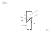
- Fig. 5 shows a sectional view of a second embodiment of the receiving surface 12 of the stem 10 and the contact surface 22 of the incisor 20 along the section line A - Fig. 3 ,
- both the receiving surface 12 of the stem 10 and the contact surface 22 of the incisor 20 have an inclined plane 34a, 34b.
- the inclined plane 34a of the receiving surface 12 of the stem 10 and the inclined plane 34b of the contact surface 22 of the incisor 20 complement each other accordingly, so that the receiving surface 12 of the stem 10 fits snugly on the contact surface 22 of the incisor 20.
- Due to these inclined planes 34a, 34b, the contact surface 30 between the master blade 10 and an incisor 20 is 56% larger than the average cross-sectional area Q of the incisor 20.
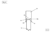
- Fig. 6 shows a sectional view of a third embodiment of the receiving surface 12 of the stem 10 and the contact surfaces 22 of the incisor 20 along the section line A - Fig. 3 ,
- both the receiving surface 12 of the stem 10 and the contact surface 22 of the incisor 20 have a V-shaped recess 36a, 36b.
- the V-shaped depression 36a of the receiving surface 12 of the stem 10 and the V-shaped depression 36b of the contact surface 22 of the incisor 20 complement each other, so that the receiving surface 12 of the stem 10 fits snugly on the contact surface 22 of the incisor 20.
- the contact surface 30 between the master blade 10 and an incisor 20 is 41% larger than the average cross-sectional area Q of the incisor 20.
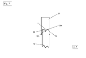
- Fig. 7 shows a sectional view of a fourth embodiment of the receiving surface 12 of the stem 10 and the contact surfaces 22 of the incisor 20 along the section line A - Fig. 3 ,
- both the receiving surface 12 of the stem 10 and the contact surface 22 of the incisor 20 have a depression with two arcs 38a, 38b leading away from the center of the contact surface.
- This depression with two from the center of the contact surface leading away arches 38a of the receiving surface 12 of the stem 10 and the recess with two leading away from the center of the contact surface arcs 38b of the contact surface 22 of the incisor 20 complement each other accordingly, so that the receiving surface 12 of the stem sheet 10 conclusive on the contact surface 22 of the incisor 20 fits.
- the contact surface 30 between the master blade 10 and an incisor 20 is 56% larger than the average cross-sectional area Q of the incisor 20.
Landscapes
- Engineering & Computer Science (AREA)
- Mechanical Engineering (AREA)
- Component Parts Of Construction Machinery (AREA)
Abstract
Sägeblatt (1) zum Bearbeiten eines Werkstückes, welches ein Stammblatt (10) mit wenigstens einer Aufnahmefläche (12) zum Halten eines Schneidezahns (20) und wenigstens ein Schneidezahn (20), welcher eine Kontaktfläche (22) zum Anbringen des Schneidezahns (20) an der Aufnahmefläche (12) des Stammblatts (10) aufweist und an dem Kreisumfang (15) des Stammblattes (10) positioniert ist, enthält. Die Berührungsfläche (30) zwischen der Aufnahmefläche (12) des Stammblatts (10) und der Kontaktfläche (22) des Schneidezahns (20) größer als die mittlere Querschnittsfläche (Q) des Schneidezahns (20).
Description
- Die vorliegende Erfindung betrifft ein Sägeblatt zum Bearbeiten eines Werkstückes. Das Sägeblatt enthält ein Stammblatt mit wenigstens einer Aufnahmefläche zum Halten eines Schneidezahns. Darüber hinaus enthält das Sägeblatt wenigstens ein Schneidezahn, welcher eine Kontaktfläche zum Anbringen des Schneidezahns an der Aufnahmefläche des Stammblatts aufweist und an dem Kreisumfang des Stammblattes positioniert ist.
- Sägeblätter der vorstehenden Art sind allgemein bekannt und dienen vorwiegend zum Bearbeiten, d.h. Durchtrennen oder Schneiden, von verschiedenen Werkstoffen beispielsweise aus metallischen, mineralischen Materialien sowie verschiedenen Kunststoffen oder Hölzern.
- Ein derartiges Sägeblatt für Kreissägen ist insbesondere in der Europäischen Patentschrift
EP-0239676 offenbart. Dieses Sägeblatt weist dabei ein Stammblatt mit einer Vielzahl an Schneidelemente auf, die entlang des Kreisumfangs des Stammblatts befestigt sind. - Nachteilig an diesen Sägeblättern des Stands der Technik ist, dass die Schneidezähne aufgrund hoher mechanischer Belastungen aus ihren Befestigungen am Stammblatt herausbrechen und die Standzeit des Sägeblatts dadurch verkürzt wird. Dies ist speziell bei dünnen Sägeblättern der Fall.
- Aufgabe der vorliegenden Erfindung ist daher das Bereitstellen eines Sägeblattes zum Bearbeiten eines Werkstückes, welche die oben genannten Nachteile beseitigt und insbesondere die Standzeit des Sägeblattes erhöht.
- Die vorstehend genannte Aufgabe wird durch den erfindungsgemässen Gegenstand des unabhängigen Anspruchs 1 gelöst. Weitere vorteilhafte Ausgestaltungen der vorliegenden Erfindung sind in den abhängen Ansprüchen beschrieben.
- Demnach wird ein Sägeblatt zum Bearbeiten eines Werkstückes bereitgestellt, welches ein Stammblatt mit wenigstens einer Aufnahmefläche zum Halten eines Schneidezahns und wenigstens ein Schneidezahn, welcher eine Kontaktfläche zum Anbringen des Schneidezahns an der Aufnahmefläche des Stammblatts aufweist und an dem Kreisumfang des Stammblattes positioniert ist, enthält.
- Erfindungsgemäss ist die Berührungsfläche zwischen der Aufnahmefläche des Stammblatts und der Kontaktfläche des Schneidezahns größer als die mittlere Querschnittsfläche des Schneidezahns.
- Gemäss einer vorteilhaften Ausgestaltungsform der vorliegenden Erfindung kann vorgesehen sein, dass die Berührungsfläche in Form einer Stufe ausgebildet ist. Hierdurch ist die Berührungsfläche 54% grösser als die mittlere Querschnittsfläche des Schneidezahns.
- Darüber hinaus ist es möglich, dass die Berührungsfläche in Form einer schiefen Ebene ausgebildet ist, wodurch die Berührungsfläche 56% grösser ist als die mittlere Querschnittsfläche des Schneidezahns.
- Um eine weitere Erhöhung der Berührungsfläche zwischen der Aufnahmefläche des Stammblatts und der Kontaktfläche des Schneidezahns zu erreichen, kann die Berührungsfläche in Form einer Nut-und-Feder-Anordnung ausgebildet sein.
- Entsprechend einer weiteren vorteilhaften Ausgestaltungsform der vorliegenden Erfindung kann die Berührungsfläche in Form einer V-förmigen Vertiefung ausgebildet sein. Hierdurch ist die Berührungsfläche 41 % grösser als die mittlere Querschnittsfläche des Schneidezahns.
- Des Weiteren kann es vorteilhaft sein, dass die Berührungsfläche in Form von zwei aus der Mitte der Berührungsfläche wegführenden Bögen ausgebildet ist, wodurch die Berührungsfläche 56% grösser ist als die mittlere Querschnittsfläche des Schneidezahns.
- Die vorliegende Erfindung wird bezüglich vorteilhafter Ausführungsbeispiele näher erläutert, hierbei zeigt
- Fig. 1
- eine Frontansicht des erfindungsgemässen Sägeblattes mit einer Vielzahl an Zähnen entlang des Kreisumfangs des Stammblattes;
- Fig. 2
- eine perspektivische Teilansicht des erfindungsgemässen Sägeblatts mit einem Schneidezahn;
- Fig. 3
- eine perspektivische Teilansicht des erfindungsgemässen Sägeblatts mit einer Vielzahl an Schneidezähnen;
- Fig. 4
- eine Schnittansicht durch einen Schneidezahn gemäß einer ersten Ausführungsform entlang der Schnittlinie A - A;
- Fig. 5
- eine Schnittansicht durch einen Schneidezahn gemäß einer zweiten Ausführungsform entlang der Schnittlinie A - A;
- Fig. 6
- eine Schnittansicht durch einen Schneidezahn gemäß einer dritten Ausführungsform entlang der Schnittlinie A - A; und
- Fig. 7
- eine Schnittansicht durch einen Schneidezahn gemäß einer vierten Ausführungsform entlang der Schnittlinie A - A.
-
Fig. 1 zeigt ein Sägeblatt 1, welches im Wesentlichen ein kreisförmiges Stammblatt 10 sowie eine Vielzahl an Schneidezähnen 20 enthält. - Das Stammblatt 10 weist dabei ein zentrisches Aufnahmeelement 11 auf, welches in Form einer kreisförmigen Bohrung ausgebildet ist. Das zentrische Aufnahmeelement 11 dient dazu das Stammblatt 10 sowie insbesondere das Sägeblatt 1 an einer nicht gezeigten Haltevorrichtung einer Werkzeugmaschine, wie z.B. einer Kreissäge, zu befestigen. Darüber hinaus enthält das Stammblatt 10 eine Vielzahl an Aufnahmeflächen 14, welche zum Halten jeweils eines Schneidezahns 20 entlang des Kreisumfangs 15 ausgebildet ist. Die Aufnahmeflächen 14 des Stammblatt 10 weisen dabei unterschiedliche Ausführungsformen auf, die nachfolgend im Detail beschrieben werden.
- Wie in
Fig. 2 und3 dargestellt, enthält jeder Schneidezahn 20 jeweils eine Kontaktfläche 22 zum Anbringen des Schneidezahns 20 an der Aufnahmefläche 12 des Stammblatts 10. Die Kontaktflächen 22 der Schneidezähne 20 weisen dabei unterschiedliche Ausführungsformen auf, die nachfolgend im Detail beschrieben werden. - Die Aufnahmefläche 12 des Stammblatts 10 sowie die Kontaktfläche 22 eines Schneidezahns 20 bilden eine Berührungsfläche 30 zwischen dem Stammblatt 10 und einem Schneidezahn 20.
- Die Anbringung der Schneidezähne 20 erfolgt durch Löten. Es ist jedoch auch möglich, dass jede andere geeignete Fügeverfahren, wie z.B. Kleben, verwendet werden kann.
-
Fig. 4 zeigt eine Schnittansicht einer ersten Ausführungsform der Aufnahmefläche 12 des Stammblatts 10 sowie der Kontaktflächen 22 des Schneidezahns 20 entlang der Schnittlinie A - A ausFig. 3 . - Gemäss dieser ersten Ausführungsform weist sowohl die Aufnahmefläche 12 des Stammblatts 10 als auch die Kontaktfläche 22 des Schneidezahns 20 eine Stufe 32a, 32b auf. Die Stufe 32a der Aufnahmefläche 12 des Stammblatts 10 und die Stufe 32b der Kontaktfläche 22 des Schneidezahns 20 ergänzen sich entsprechend, so dass die Aufnahmefläche 12 des Stammblatts 10 schlüssig auf die Kontaktfläche 22 des Schneidezahns 20 passt. Durch diese Stufen 32a, 32b ist Berührungsfläche 30 zwischen dem Stammblatt 10 und einem Schneidezahn 20 um 54% grösser als die mittlere Querschnittsfläche Q des Schneidezahns 20.
-
Fig. 5 zeigt eine Schnittansicht einer zweiten Ausführungsform der Aufnahmefläche 12 des Stammblatts 10 sowie der Kontaktfläche 22 des Schneidezahns 20 entlang der Schnittlinie A - A ausFig. 3 . - Gemäss dieser zweiten Ausführungsform weist sowohl die Aufnahmefläche 12 des Stammblatts 10 als auch die Kontaktfläche 22 des Schneidezahns 20 eine schiefe Ebene 34a, 34b auf. Die schiefe Ebene 34a der Aufnahmefläche 12 des Stammblatts 10 und die schiefe Ebene 34b der Kontaktfläche 22 des Schneidezahns 20 ergänzen sich entsprechend, so dass die Aufnahmefläche 12 des Stammblatts 10 schlüssig auf die Kontaktfläche 22 des Schneidezahns 20 passt. Durch diese schiefen Ebenen 34a, 34b ist Berührungsfläche 30 zwischen dem Stammblatt 10 und einem Schneidezahn 20 um 56% grösser als die mittlere Querschnittsfläche Q des Schneidezahns 20.
-
Fig. 6 zeigt eine Schnittansicht einer dritten Ausführungsform der Aufnahmefläche 12 des Stammblatts 10 sowie der Kontaktflächen 22 des Schneidezahns 20 entlang der Schnittlinie A - A ausFig. 3 . - Gemäss dieser dritten Ausführungsform weist sowohl die Aufnahmefläche 12 des Stammblatts 10 als auch die Kontaktfläche 22 des Schneidezahns 20 eine V-förmige Vertiefung 36a, 36b auf. Die V-förmige Vertiefung 36a der Aufnahmefläche 12 des Stammblatts 10 und die V-förmige Vertiefung 36b der Kontaktfläche 22 des Schneidezahns 20 ergänzen sich entsprechend, so dass die Aufnahmefläche 12 des Stammblatts 10 schlüssig auf die Kontaktfläche 22 des Schneidezahns 20 passt. Durch diese V-förmige Vertiefungen 36a, 36b ist Berührungsfläche 30 zwischen dem Stammblatt 10 und einem Schneidezahn 20 um 41% grösser als die mittlere Querschnittsfläche Q des Schneidezahns 20.
-
Fig. 7 zeigt eine Schnittansicht einer vierten Ausführungsform der Aufnahmefläche 12 des Stammblatts 10 sowie der Kontaktflächen 22 des Schneidezahns 20 entlang der Schnittlinie A - A ausFig. 3 . - Gemäss dieser vierten Ausführungsform weist sowohl die Aufnahmefläche 12 des Stammblatts 10 als auch die Kontaktfläche 22 des Schneidezahns 20 eine Vertiefung mit zwei aus der Mitte der Berührungsfläche wegführenden Bögen 38a, 38b auf. Diese Vertiefung mit zwei aus der Mitte der Berührungsfläche wegführenden Bögen 38a der Aufnahmefläche 12 des Stammblatts 10 und die Vertiefung mit zwei aus der Mitte der Berührungsfläche wegführenden Bögen 38b der Kontaktfläche 22 des Schneidezahns 20 ergänzen sich entsprechend, so dass die Aufnahmefläche 12 des Stammblatts 10 schlüssig auf die Kontaktfläche 22 des Schneidezahns 20 passt. Durch diese Vertiefungen mit zwei aus der Mitte der Berührungsfläche wegführenden Bögen 38a, 38b ist Berührungsfläche 30 zwischen dem Stammblatt 10 und einem Schneidezahn 20 um 56% grösser als die mittlere Querschnittsfläche Q des Schneidezahns 20.
Claims (6)
- Sägeblatt (1) zum Bearbeiten eines Werkstückes enthaltend- ein Stammblatt (10) mit wenigstens einer Aufnahmefläche (12) zum Halten eines Schneidezahns (20), und- wenigstens ein Schneidezahn (20), welcher eine Kontaktfläche (22) zum Anbringen des Schneidezahns (20) an der Aufnahmefläche (12) des Stammblatts (10) aufweist und an dem Kreisumfang (15) des Stammblattes (10) positioniert ist,dadurch gekennzeichnet, dass die Berührungsfläche (30) zwischen der Aufnahmefläche (12) des Stammblatts(10) und der Kontaktfläche (22) des Schneidezahns (20) größer ist als die mittlere Querschnittsfläche (Q) des Schneidezahns (20).
- Sägeblatt (1) nach Anspruch 1,
dadurch gekennzeichnet, dass die Berührungsfläche (30) in Form einer Stufe (32a, 32b) ausgebildet ist. - Sägeblatt (1) nach Anspruch 1,
dadurch gekennzeichnet, dass die Berührungsfläche (30) in Form einer schiefen Ebene (34a, 34b) ausgebildet ist. - Sägeblatt (1) nach Anspruch 1,
dadurch gekennzeichnet, dass die Berührungsfläche (30) in Form einer Nut-und-Feder-Anordnung ausgebildet ist. - Sägeblatt (1) nach Anspruch 1,
dadurch gekennzeichnet, dass die Berührungsfläche (30) in Form einer V-förmigen Vertiefung (36a, 36b) ausgebildet ist. - Sägeblatt (1) nach Anspruch 1,
dadurch gekennzeichnet, dass die Berührungsfläche (30) in Form von zwei aus der Mitte der Berührungsfläche wegführenden Bögen (38a, 38b) ausgebildet ist.
Priority Applications (1)
| Application Number | Priority Date | Filing Date | Title |
|---|---|---|---|
| EP13165888.2A EP2799177A1 (de) | 2013-04-30 | 2013-04-30 | Kreissägeblatt mit erhöhter Kontaktfläche zu Schneidelementen |
Applications Claiming Priority (1)
| Application Number | Priority Date | Filing Date | Title |
|---|---|---|---|
| EP13165888.2A EP2799177A1 (de) | 2013-04-30 | 2013-04-30 | Kreissägeblatt mit erhöhter Kontaktfläche zu Schneidelementen |
Publications (1)
| Publication Number | Publication Date |
|---|---|
| EP2799177A1 true EP2799177A1 (de) | 2014-11-05 |
Family
ID=48190812
Family Applications (1)
| Application Number | Title | Priority Date | Filing Date |
|---|---|---|---|
| EP13165888.2A Withdrawn EP2799177A1 (de) | 2013-04-30 | 2013-04-30 | Kreissägeblatt mit erhöhter Kontaktfläche zu Schneidelementen |
Country Status (1)
| Country | Link |
|---|---|
| EP (1) | EP2799177A1 (de) |
Citations (10)
| Publication number | Priority date | Publication date | Assignee | Title |
|---|---|---|---|---|
| GB537764A (en) * | 1940-04-06 | 1941-07-04 | Reginald Frederick Knowlson | Improvements in rotary cutting tools such as circular saws |
| US2675603A (en) * | 1952-04-23 | 1954-04-20 | Earl G Goehle | Composite circular saw |
| US3146561A (en) * | 1961-05-01 | 1964-09-01 | Frederick W Lindblad | Circular saw and method of making the same |
| JPH01135413A (ja) * | 1987-11-16 | 1989-05-29 | Ochiai Yoshio | チツプソー |
| JPH05401A (ja) * | 1991-06-21 | 1993-01-08 | Motoyuki:Kk | チツプソー |
| US20040128836A1 (en) * | 2001-01-22 | 2004-07-08 | Robert Garrett | RoofmatesTM shinglesawTM |
| JP2005022416A (ja) * | 2004-08-20 | 2005-01-27 | Chipsaw Japan:Kk | チップソー及びその製造方法 |
| EP1820618A1 (de) * | 2006-02-16 | 2007-08-22 | Tyrolit Schleifmittelwerke Swarovski KG | Schneidwerkzeug |
| WO2010148471A1 (en) * | 2009-06-23 | 2010-12-29 | Scies B.G.R. Inc. | Saw tooth tip |
| EP2495061A1 (de) * | 2011-03-01 | 2012-09-05 | AKE Knebel GmbH & Co. KG | Sägeblatt |
-
2013
- 2013-04-30 EP EP13165888.2A patent/EP2799177A1/de not_active Withdrawn
Patent Citations (10)
| Publication number | Priority date | Publication date | Assignee | Title |
|---|---|---|---|---|
| GB537764A (en) * | 1940-04-06 | 1941-07-04 | Reginald Frederick Knowlson | Improvements in rotary cutting tools such as circular saws |
| US2675603A (en) * | 1952-04-23 | 1954-04-20 | Earl G Goehle | Composite circular saw |
| US3146561A (en) * | 1961-05-01 | 1964-09-01 | Frederick W Lindblad | Circular saw and method of making the same |
| JPH01135413A (ja) * | 1987-11-16 | 1989-05-29 | Ochiai Yoshio | チツプソー |
| JPH05401A (ja) * | 1991-06-21 | 1993-01-08 | Motoyuki:Kk | チツプソー |
| US20040128836A1 (en) * | 2001-01-22 | 2004-07-08 | Robert Garrett | RoofmatesTM shinglesawTM |
| JP2005022416A (ja) * | 2004-08-20 | 2005-01-27 | Chipsaw Japan:Kk | チップソー及びその製造方法 |
| EP1820618A1 (de) * | 2006-02-16 | 2007-08-22 | Tyrolit Schleifmittelwerke Swarovski KG | Schneidwerkzeug |
| WO2010148471A1 (en) * | 2009-06-23 | 2010-12-29 | Scies B.G.R. Inc. | Saw tooth tip |
| EP2495061A1 (de) * | 2011-03-01 | 2012-09-05 | AKE Knebel GmbH & Co. KG | Sägeblatt |
Similar Documents
| Publication | Publication Date | Title |
|---|---|---|
| EP2404689B1 (de) | Dentalwekzeug | |
| DE112013003566B4 (de) | Sägeblatt und Verfahren zum Anordnen von Sägezähnen | |
| DE202015106360U1 (de) | Fräserkopfeinheit, Fräserschaft und Aufschraubfräser | |
| EP3694670B1 (de) | Wälzschälwerkzeug | |
| DE102010010589B4 (de) | Dental- oder chirurgisches Werkzeug | |
| EP2570216B1 (de) | Sägeblatt mit Leistungszähnen und Oberflächenzähnen | |
| EP2484471A1 (de) | Bearbeitungswerkzeug | |
| DE102016212611A1 (de) | Rotierendes Schneidwerkzeug mit Klingen mit sich wiederholender ungleicher Teilung und ungleichen Steigungswinkeln | |
| DE102015004182A1 (de) | Kreissägeblatt mit Gruppenverzahnung | |
| EP2901961B1 (de) | Dentalinstrument | |
| DE202009012569U1 (de) | Einlippen-Tieflochbohrer | |
| EP2650091A2 (de) | Schneidenmesser | |
| WO2008028462A1 (de) | Schruppfräser | |
| WO2005002768A1 (de) | Vorrichtung zur bearbeitung und/oder herstellung einer vertiefung in einem werkstück | |
| DE102015210864B4 (de) | Kupplungsanordnung | |
| DE1627238B2 (de) | Reibahle | |
| DE102010005580A1 (de) | Schneidwerkzeug mit kegelstumpfförmigen Schneidelementen | |
| DE202009010943U1 (de) | Werkzeug zur spanabhebenden Bearbeitung von Werkstücken | |
| DE102009019394A1 (de) | Wälzfräser | |
| DE102005032761A1 (de) | Messerkopf | |
| DE1752707A1 (de) | Abwaelzfraeser | |
| DE19622118B4 (de) | Mehrfachsägenanordnung zum Schneiden von Platten aus blockförmigem Material | |
| EP0029113B1 (de) | Streckenstab für Streckwerke von Textilvorbereitungsmaschinen | |
| DE202015107160U1 (de) | Bidirektional verstellbarer Schneidewerkzeughalter | |
| DE102010035652B4 (de) | Zahnstange mit verbesserter Steifigkeit |
Legal Events
| Date | Code | Title | Description |
|---|---|---|---|
| PUAI | Public reference made under article 153(3) epc to a published international application that has entered the european phase |
Free format text: ORIGINAL CODE: 0009012 |
|
| 17P | Request for examination filed |
Effective date: 20130430 |
|
| AK | Designated contracting states |
Kind code of ref document: A1 Designated state(s): AL AT BE BG CH CY CZ DE DK EE ES FI FR GB GR HR HU IE IS IT LI LT LU LV MC MK MT NL NO PL PT RO RS SE SI SK SM TR |
|
| AX | Request for extension of the european patent |
Extension state: BA ME |
|
| STAA | Information on the status of an ep patent application or granted ep patent |
Free format text: STATUS: THE APPLICATION IS DEEMED TO BE WITHDRAWN |
|
| 18D | Application deemed to be withdrawn |
Effective date: 20150507 |