EP0239676A1 - Sägeblatt - Google Patents
Sägeblatt Download PDFInfo
- Publication number
- EP0239676A1 EP0239676A1 EP86117388A EP86117388A EP0239676A1 EP 0239676 A1 EP0239676 A1 EP 0239676A1 EP 86117388 A EP86117388 A EP 86117388A EP 86117388 A EP86117388 A EP 86117388A EP 0239676 A1 EP0239676 A1 EP 0239676A1
- Authority
- EP
- European Patent Office
- Prior art keywords
- incisions
- saw blade
- blade according
- circular
- edge
- Prior art date
- Legal status (The legal status is an assumption and is not a legal conclusion. Google has not performed a legal analysis and makes no representation as to the accuracy of the status listed.)
- Granted
Links
Images

Classifications
-
- B—PERFORMING OPERATIONS; TRANSPORTING
- B23—MACHINE TOOLS; METAL-WORKING NOT OTHERWISE PROVIDED FOR
- B23D—PLANING; SLOTTING; SHEARING; BROACHING; SAWING; FILING; SCRAPING; LIKE OPERATIONS FOR WORKING METAL BY REMOVING MATERIAL, NOT OTHERWISE PROVIDED FOR
- B23D61/00—Tools for sawing machines or sawing devices; Clamping devices for these tools
- B23D61/02—Circular saw blades
- B23D61/04—Circular saw blades with inserted saw teeth, i.e. the teeth being individually inserted
-
- B—PERFORMING OPERATIONS; TRANSPORTING
- B23—MACHINE TOOLS; METAL-WORKING NOT OTHERWISE PROVIDED FOR
- B23D—PLANING; SLOTTING; SHEARING; BROACHING; SAWING; FILING; SCRAPING; LIKE OPERATIONS FOR WORKING METAL BY REMOVING MATERIAL, NOT OTHERWISE PROVIDED FOR
- B23D61/00—Tools for sawing machines or sawing devices; Clamping devices for these tools
- B23D61/02—Circular saw blades
- B23D61/025—Details of saw blade body
- B23D61/0275—Slots in the saw blade body for reducing tension or vibration
-
- B—PERFORMING OPERATIONS; TRANSPORTING
- B24—GRINDING; POLISHING
- B24D—TOOLS FOR GRINDING, BUFFING OR SHARPENING
- B24D5/00—Bonded abrasive wheels, or wheels with inserted abrasive blocks, designed for acting only by their periphery; Bushings or mountings therefor
- B24D5/12—Cut-off wheels
- B24D5/123—Cut-off wheels having different cutting segments
Definitions
- the invention relates to a saw blade for circular saws, in which incisions are provided which extend essentially radially inwards from the edge.
- the invention relates to the problem of noise damping with rotating saw blades.
- Saw blades for stone saws usually have a circular circumference without teeth with radial slots made at regular intervals. An edge along the circumference is covered with an abrasion or abrasive material.
- Circular sawing machines generate considerable noise. This noise is essentially caused by vibrations of the saw blade. There are noise levels of around 90 dB (A) and more. It is known to dampen these vibrations and thus to reduce the noise at the edge of the saw blade by means of scissors radial slots, the material is then flattened again so that the cut surfaces rub against each other. When the saw blade vibrates, the cut surfaces rub against each other, whereby vibrational energy is converted into heat and the vibrations are thereby dampened.
- the invention has for its object to provide the quietest possible saw blade.
- this object is achieved in the case of a saw blade with incisions on the circumference in that the incisions are undulating.
- substantially radially extending and undulating incisions are preferably provided in the inner region of the saw blade.
- the incisions are expediently made such that an annular stress zone which is not interrupted by incisions is formed between the region in which the circumferential incisions are provided and the region in which the internal incisions are provided.
- the incisions can be made, for example, by means of a laser beam.
- An advantageously very small width of the incisions of a few hundredths of a millimeter can thereby be achieved.
- other fineblanking means such as spark erosion can also be used.
- the incisions can end in rounded openings to prevent tearing of the material.
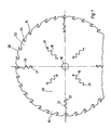
- the saw blade 10 in FIGS. 1 and 2 has notches 12 on its circumference which extend essentially radially inwards and run in an undulating manner.
- the incisions 12 each start from the bottom of a chip space 14.
- further radially extending and undulating incisions 16 are provided in the inner region of the saw blade at a distance from a central hole 18.
- the incisions 16 in the interior are angularly arranged between adjacent incisions on the circumference.
- annular stress zone 20 which is not interrupted by notches is formed.
- the incisions 12 and 16 are made, for example, by means of a laser beam or spark erosion and are only a few hundredths of a millimeter wide. They end in rounded openings 21.
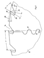
- the geometry of the toothing of the saw blade 10 is specially designed to support the noise damping.
- the chip space 14 is made as small as possible, but still so large that it cannot become clogged.
- a full steel blade e.g. in chrome vanadium steel as well as a master blade with carbide tipped - as shown in the illustration.
- the cutting edges 24 of the teeth 22 are formed by hard metal inserts 26. It is a wide tooth division, i.e. a small number of teeth, here thirty-two teeth, with elongated tooth backs 28 (FIG. 2), as a result of which the chip thickness is limited.
- the angle ⁇ between the cutting edges 24 and the radii running through the tips of the inserts 26 is preferably 20 °.
- the angle ⁇ between the back 30 of the insert 26 and the tangent extending through the tip of the insert 26 is preferably 20 °.
- the angle ⁇ denotes the opening angle of the chip space 14.
- the angles ⁇ and ⁇ can also be smaller or larger, depending on the intended use of the saw blade.
- Fig. 3 shows a saw blade for a stone saw, in which a noise reduction is effected in a corresponding manner.
- a saw blade 32 for a stone saw has a circular circumference without teeth. Radial incisions 34 extend from the circumference and are arranged at equal angular intervals. An edge 36 along the circumference is covered with an abrasion or abrasive material. This is the usual formation of a saw blade for stone circular saws.
- Wavy cuts 38 extend substantially radially inward from the periphery, or the bottom, of some of the cuts 34.
- four such wavy incisions 38 are each offset by 90 ° from one another.
- four substantially radially extending and undulating incisions 40 are made in the inner region of the saw blade 32.
- the incisions 40 are offset from one another by 90 ° and at an angle of 45 ° to the incisions 38.
- annular stress zone 42 which is not interrupted by incisions is also formed here.
Landscapes
- Engineering & Computer Science (AREA)
- Mechanical Engineering (AREA)
- Sawing (AREA)
- Polishing Bodies And Polishing Tools (AREA)
- Processing Of Stones Or Stones Resemblance Materials (AREA)
- Power Steering Mechanism (AREA)
- Harvester Elements (AREA)
- Rotary Pumps (AREA)
Abstract
Description
- Die Erfindung betrifft ein Sägeblatt für Kreissägen, bei welchem vom Rand aus sich im wesentlichen radial einwärts erstreckende Einschnitte vorgesehen sind.
- Speziell bezieht sich die Erfindung auf das Problem der Geräuschdämpfung bei umlaufenden Sägeblättern.
- Es kann sich dabei um Kreissägeblätter handeln, die zur spanenden Bearbeitung von Werkstoffen, wie Holz, Kunststoff oder Metall, mit definierten Schneiden (=Sägezähnen) ausgestattet sind. Es können aber auch Kressägeblätter sein, wie sie zur Sternbearbeitung Verwendung finden. Diese sind am Umfang mit Segmenten besetzt, in welchen schleifende Körner vorzugsweise aus Hartmetallen und Diamanten eingebettet sind und die undefinierte Schneiden bilden.
- Bei bekannten Sägeblättern für Kreissägen sind vom Umfang des Sägeblattes vom Grund eines Spanraumes ausgehende einschnitte vorgesehen, die jeweils in einem kreisrunden Durchbruch auslaufen. Das sind Dehnungsschlitze, welche die thermische Ausdehnung bei der Erwärmung des Sägeblattes im Betrieb auf nehmen sollen. In einem Innenbereich des Sägeblattes wird zur Erhöhung der Stabilität eine ringförmige Spannungszone angebracht.
- Sägeblätter für Steintrennsägen haben üblicherweise einen kreisrunden Umfang ohne Zähne mit in regelmäßigen Abständen angebrachten radialen Schlitzen. Ein Rand längs des Umfangs ist mit einem Abrieb- oder Schleifmaterial besetzt.
- Kreissägemaschinen erzeugen erheblichen Lärm. Dieser Lärm wird im wesentlichen durch Schwingungen des Sägeblattes hervorgerufen. Es entstehen Geräuschpegel von etwa 90 dB(A) und mehr. Es ist bekannt, zur Dämpfung dieser Schwingungen und damit zur Verminderung des Lärms am Rand des Sägeblattes mittels einer Schere radiale Schlitze anzubringen, wobei das Material anschließend wieder flachgedrückt wird, so daß die Schnittflächen reibend aneinander anliegen. Bei Schwingungen des Sägeblattes reiben die Schnittflächen aufeinander, wobei Schwingungsenergie in Wärme umgesetzt und die Schwingungen dadurch gedämpft werden.
- Es sind auch Versuche gemacht worden, den durch das Sägeblatt hervorgerufenen Lärm durch besondere Zahngeometrie, d.h. Ausbildung der Zähne und der Spanräume zu reduzieren.
- Der Erfindung liegt die Aufgabe zugrunde, ein möglichst leises Sägeblatt zu schaffen.
- Erfindungsgemäß wird diese Aufgabe bei einem Sägeblatt mit Einschnitten am Umfang dadurch gelöst, daß die Einschnitte wellenförmig verlaufen.
- Es hat sich überraschenderweise gezeigt, daß sich durch solche wellenförmigen Einschnitte eine erhebliche Verminderung des durch das Sägeblatt hervorgerufenen Lärms erzielen läßt.
- Vorzugsweise sind im Innenbereich des Sägeblattes weitere, sich im wesentlichen radial erstreckende und wellenförmig verlaufende Einschnitte vorgesehen.
- Die Einschnitte sind dabei zweckmäßigerweise so angebracht, daß zwischen dem Bereich, in welchem die Einschnitte am Umfang vorgesehen sind und dem Bereich, in welchem die inneren Einschnitte vorgesehen sind, eine nicht durch Einschnitte unterbrochene, ringförmige Spannungszone ausgebildet ist.
- Die Einschnitte können beispielsweise mittels eines Laserstrahles angebracht sein. Es kann dadurch eine vorteilhaft sehr geringe Breite der Einschnitte von einigen Hundertstelmillimeter erzielt werden. Anstelle eines Laserstrahls können auch andere Feinschneidemittel wie Funkenerosion verwendet werden.
- Die Einschnitte können in gerundeten Durchbrüchen enden, um ein Einreißen des Materials zu verhindern.
- Ausführungsbeispiele der Erfindung sind nachstehend unter Bezugnahme auf die zugehörigen Zeichnungen näher erläutert.
- Fig. 1 zeigt abgebrochen ein Sägeblatt für Kreissägen, das mit wellenförmigen Einschnitten versehen ist.
- Fig. 2 zeigt in vergrößertem Maßstab die Zahnung des Sägeblattes.
- Fig. 3 zeigt ein Sägeblatt für Steinkreissägen, das ebenfalls mit wellenförmigen Einschnitten zur Geräuschdämpfung versehen ist.
- Das Sägeblatt 10 in Fig.1 und 2 weist an seinem Umfang Einschnitte 12 auf, die sich im wesentlichen radial einwärts erstrecken und wellenförmig verlaufen. Die Einschnitte 12 gehen jeweils vom Grund eines Spanraumes 14 aus. Weitere sich im wesentlichen radial erstreckende und wellenförmig verlaufende Einschnitte 16 sind in dem Innenbereich des Sägeblattes jedoch im Abstand von einem zentralen Loch 18 vorgesehen. Die Einschnitte 16 im Innenbereich sind winkelmäßig jeweils zwischen benachbarten Einschnitten am Umfang angeordnet. Zwischen dem Bereich, in welchem die Einschnitte 12 am Umfang vorgesehen sind, und dem Bereich, in welchem die inneren Einschnitte 16 vorgesehen sind, ist eine nicht durch Einschnitte unterbrochene, ringförmige Spannungszone 20 ausgebildet.
- Die Einschnitte 12 und 16 sind zum Beispiel mittels eines Laserstrahles oder einer Funkenerosion angebracht und nur wenige Hundertstelmillimeter breit. Sie enden in gerundeten Durchbrüchen 21. Zur Unterstützung der Geräuschdämpfung ist die Geometrie der Zahnung des Sägeblattes 10 besonders ausgebildet.
- Bei der Ausführung nach Fig.1 als Kreissägeblatt zur Holzbearbeiting ist der Spanraum 14 möglichst klein gemacht, allerdings noch so groß, daß er sich nicht zusetzen kann. Als Material für das Sägeblatt kann sowohl ein Vollstahlblatt z.B. in Chrom-Vanadiumstahl als auch ein Stammblatt mit Hartmetallbestückung - wie in der Darstellung abgebildet - Verwendung finden. In der Darstellung sind die Schneidkanten 24 der Zähne 22 von Hartmetalleinsätzen 26 gebildet. Es ist eine weite Zahnteilung, d.h. eine geringe Zähnezahl, hier zweiunddreißig Zähne, mit langgestreckten Zahnrücken 28 vorgesehen (Fig.2), wodurch die Spandicke begrenzt wird. Der Winkel γ zwischen den Schneidkanten 24 und den durch die Spitzen der Einsätze 26 verlaufenden Radien beträgt vorzugsweise 20°. Ebenso beträgt der Winkel α zwischen dem Rücken 30 des Einsatzes 26 und der durch die Spitze des Einsatzes 26 verlaufenden Tangente vorzugsweise 20°. Der Winkel δ bezeichnet den Öffnungswinkel des Spanraums 14. Die Winkel γ und α können aber auch, je nach Einsatzzweck des Sägeblattes, kleiner oder größer sein.
- Mit einem Sägeblatt der beschriebenen Art läßt sich gegenüber einem gleich großen Sägeblatt ohne Lärmschutzmaßnahmen eine Verbesserung des Lärmpegels bis etwa 10 dB(A) erzielen.
- Fig. 3 zeigt ein Sägeblatt für eine Steintrennsäge, bei welchem in entsprechender Weise eine Geräuschdämpfung bewirkt wird.
- Ein Sägeblatt 32 für eine Steintrennsäge weist einen kreisrunden Umfang ohne Zähne auf. Von dem Umfang gehen radiale Einschnitte 34 aus, die in gleichen winkelabständen angeordnet sind. Ein Rand 36 Längs des Umfangs ist mit einem Abrieb- oder Schleifmaterial besetzt. Das ist die übliche Ausbildung eines Sägeblattes für Steinkreissägen.
- Vom Umfang, oder vom Grund einiger der Einschnitte 34, verlaufen wellenförmige Einschnitte 38 im wesentlichen radial einwärts. Bei der dargestellten Ausführung sind vier solcher wellenförmiger Einschnitte 38 jeweils um 90° gegeneinander winkelversetzt angeordnet. Auch hier sind im Innenbereich des Sägeblattes 32 vier im wesentlichen radial sich erstreckende und wellenförmig verlaufende Einschnitte 40 angebracht. Die Einschnitte 40 sind um jeweils 90° gegeneinander und um 45° gegen die Einschnitte 38 winkelversetzt. Zwischen dem Bereich, in welchem die Einschnitte 38 vom Rand vorgesehen sind, und dem Bereich, in welchem die inneren Einschnitte vorgesehen sind, ist auch hier eine nicht durch Einschnitte unterbrochene, ringförmige Spannungszone 42 ausgebildet.
Claims (8)
Priority Applications (1)
| Application Number | Priority Date | Filing Date | Title |
|---|---|---|---|
| AT86117388T ATE43525T1 (de) | 1986-04-04 | 1986-12-13 | Saegeblatt. |
Applications Claiming Priority (2)
| Application Number | Priority Date | Filing Date | Title |
|---|---|---|---|
| DE19863611207 DE3611207A1 (de) | 1986-04-04 | 1986-04-04 | Saegeblatt fuer kreissaegen |
| DE3611207 | 1986-04-04 |
Publications (2)
| Publication Number | Publication Date |
|---|---|
| EP0239676A1 true EP0239676A1 (de) | 1987-10-07 |
| EP0239676B1 EP0239676B1 (de) | 1989-05-31 |
Family
ID=6297856
Family Applications (1)
| Application Number | Title | Priority Date | Filing Date |
|---|---|---|---|
| EP86117388A Expired EP0239676B1 (de) | 1986-04-04 | 1986-12-13 | Sägeblatt |
Country Status (3)
| Country | Link |
|---|---|
| EP (1) | EP0239676B1 (de) |
| AT (1) | ATE43525T1 (de) |
| DE (2) | DE3611207A1 (de) |
Cited By (8)
| Publication number | Priority date | Publication date | Assignee | Title |
|---|---|---|---|---|
| US5758561A (en) * | 1995-09-26 | 1998-06-02 | Black & Decker Inc. | Circular saw blade and method |
| US5896800A (en) * | 1995-09-26 | 1999-04-27 | Black & Decker Inc. | Circular saw blade |
| US7156010B2 (en) * | 2004-11-22 | 2007-01-02 | Tenryu Seiko Kabushiki Kaisha | Disk cutter |
| CN105922456A (zh) * | 2016-06-23 | 2016-09-07 | 江苏锋泰工具有限公司 | 消声金刚石锯片 |
| CN105921816A (zh) * | 2016-06-23 | 2016-09-07 | 江苏锋泰工具有限公司 | 消声金刚石锯片的制备方法 |
| CN106113284A (zh) * | 2016-06-23 | 2016-11-16 | 江苏锋泰工具有限公司 | 低噪声金刚石锯片 |
| EP3260227A1 (de) * | 2016-06-23 | 2017-12-27 | KEURO Besitz GmbH & Co. EDV-Dienstleistungs KG | Sägeblatt für eine kreissäge, verfahren zum herstellen eines sägeblatts und kreissägemaschine |
| US10279407B2 (en) | 2015-10-30 | 2019-05-07 | Black & Decker Inc. | Circular saw blades |
Families Citing this family (12)
| Publication number | Priority date | Publication date | Assignee | Title |
|---|---|---|---|---|
| DE8814351U1 (de) * | 1988-11-17 | 1989-03-23 | AKE Knebel GmbH + Co. Werkzeugfabrik, 7460 Balingen | Kreissägeblatt |
| DE9108113U1 (de) * | 1991-03-21 | 1991-11-14 | Mawe Wetter GmbH Werkzeuge und Maschinen, 32584 Löhne | Kreissägeblatt |
| DE9216744U1 (de) * | 1992-12-09 | 1993-01-28 | Gebr. Leitz Gmbh & Co, 7082 Oberkochen | Kreissägeblatt |
| DE4328482C2 (de) * | 1993-08-24 | 1998-01-29 | Fgw Forsch Werkzeuge Werkstoff | Kreissägeblatt |
| USD382786S (en) | 1995-03-02 | 1997-08-26 | Black & Decker Inc. | Circular saw blade with heat vents |
| USD383368S (en) | 1996-03-15 | 1997-09-09 | Black & Decker Inc. | Saw blade with vents |
| USD388318S (en) | 1996-03-15 | 1997-12-30 | Black & Decker Inc. | Decorative vent pattern for circular saw blades |
| DE19648129A1 (de) * | 1996-11-21 | 1998-05-28 | Lauffer Adelbert Dipl Ing Fh | Kreissägeblatt |
| USD442979S1 (en) | 1997-02-07 | 2001-05-29 | Black & Decker Inc. | Decorative slot pattern for circular saw blades |
| DE20108572U1 (de) * | 2001-05-21 | 2002-10-02 | KOHNLE GmbH Hartmetall-Werkzeug-Fabrik, 83059 Kolbermoor | Kreissägeblatt |
| DE102010043606A1 (de) * | 2010-11-09 | 2012-05-10 | Robert Bosch Gmbh | Drehoszillationssägeblatt für eine Werkzeugmaschine |
| DE102024111227A1 (de) * | 2024-04-22 | 2025-10-23 | Koll & Cie. GmbH & Co KG | Kreissägeblatt für Holz |
Citations (5)
| Publication number | Priority date | Publication date | Assignee | Title |
|---|---|---|---|---|
| US1083645A (en) * | 1912-09-23 | 1914-01-06 | Jacob Wettstein | Circular saw-blade. |
| FR790329A (fr) * | 1935-05-22 | 1935-11-19 | Perfectionnement destiné à maintenir la tension des scies circulaires | |
| WO1985001242A1 (en) * | 1983-09-09 | 1985-03-28 | The Peerless Saw Company | Saw blade or blank having self plugging stress relief means |
| EP0141042A1 (de) * | 1983-08-27 | 1985-05-15 | Heinrich Mummenhoff | Kreissägeblatt |
| DE3405407A1 (de) * | 1984-02-15 | 1985-08-22 | Fa. Röttger Jansen-Herfeld, 5630 Remscheid | Geraeuschgedaempftes kreissaegeblatt mit radialer teilung |
-
1986
- 1986-04-04 DE DE19863611207 patent/DE3611207A1/de not_active Withdrawn
- 1986-12-13 DE DE8686117388T patent/DE3663631D1/de not_active Expired
- 1986-12-13 EP EP86117388A patent/EP0239676B1/de not_active Expired
- 1986-12-13 AT AT86117388T patent/ATE43525T1/de not_active IP Right Cessation
Patent Citations (5)
| Publication number | Priority date | Publication date | Assignee | Title |
|---|---|---|---|---|
| US1083645A (en) * | 1912-09-23 | 1914-01-06 | Jacob Wettstein | Circular saw-blade. |
| FR790329A (fr) * | 1935-05-22 | 1935-11-19 | Perfectionnement destiné à maintenir la tension des scies circulaires | |
| EP0141042A1 (de) * | 1983-08-27 | 1985-05-15 | Heinrich Mummenhoff | Kreissägeblatt |
| WO1985001242A1 (en) * | 1983-09-09 | 1985-03-28 | The Peerless Saw Company | Saw blade or blank having self plugging stress relief means |
| DE3405407A1 (de) * | 1984-02-15 | 1985-08-22 | Fa. Röttger Jansen-Herfeld, 5630 Remscheid | Geraeuschgedaempftes kreissaegeblatt mit radialer teilung |
Cited By (11)
| Publication number | Priority date | Publication date | Assignee | Title |
|---|---|---|---|---|
| US5758561A (en) * | 1995-09-26 | 1998-06-02 | Black & Decker Inc. | Circular saw blade and method |
| US5896800A (en) * | 1995-09-26 | 1999-04-27 | Black & Decker Inc. | Circular saw blade |
| US6065370A (en) * | 1995-09-26 | 2000-05-23 | Black & Decker Inc. | Circular saw blade and method |
| US7156010B2 (en) * | 2004-11-22 | 2007-01-02 | Tenryu Seiko Kabushiki Kaisha | Disk cutter |
| US10279407B2 (en) | 2015-10-30 | 2019-05-07 | Black & Decker Inc. | Circular saw blades |
| CN105922456A (zh) * | 2016-06-23 | 2016-09-07 | 江苏锋泰工具有限公司 | 消声金刚石锯片 |
| CN105921816A (zh) * | 2016-06-23 | 2016-09-07 | 江苏锋泰工具有限公司 | 消声金刚石锯片的制备方法 |
| CN106113284A (zh) * | 2016-06-23 | 2016-11-16 | 江苏锋泰工具有限公司 | 低噪声金刚石锯片 |
| EP3260227A1 (de) * | 2016-06-23 | 2017-12-27 | KEURO Besitz GmbH & Co. EDV-Dienstleistungs KG | Sägeblatt für eine kreissäge, verfahren zum herstellen eines sägeblatts und kreissägemaschine |
| CN106113284B (zh) * | 2016-06-23 | 2018-02-02 | 江苏锋泰工具有限公司 | 低噪声金刚石锯片 |
| US11167362B2 (en) | 2016-06-23 | 2021-11-09 | Keuro Besitz Gmbh & Co. Edv-Dienstleistungs Kg | Sawblade for a circular saw, method for producing a sawblade, and circular sawing machine |
Also Published As
| Publication number | Publication date |
|---|---|
| DE3611207A1 (de) | 1987-10-08 |
| EP0239676B1 (de) | 1989-05-31 |
| DE3663631D1 (en) | 1989-07-06 |
| ATE43525T1 (de) | 1989-06-15 |
Similar Documents
| Publication | Publication Date | Title |
|---|---|---|
| EP0239676B1 (de) | Sägeblatt | |
| EP0120244B1 (de) | Sägeblatt | |
| DE69306165T2 (de) | Diamantenschneiden mit geänderter Schneidkantengeometrie und ihre Montageanordnung am Bohrmeissel | |
| DE2615609A1 (de) | Fraeswerkzeug | |
| EP1114241B1 (de) | Dichtring für nicht-hermetische fluiddichtungen | |
| EP1867420B1 (de) | Sägeblatt mit Seitenschlag | |
| DE8017100U1 (de) | Trennscheibe | |
| DE69936254T2 (de) | Diamanttrennscheibe und deren herstellungsverfahren | |
| DE2753509C2 (de) | Sägeblatt | |
| DE4243480A1 (de) | Trockensägeblatt | |
| EP0958907B1 (de) | Kreisscheibenförmiges Werkzeug mit Stossabsorptionsfähigkeit | |
| EP3110364B1 (de) | Dentalinstrument | |
| DE69307280T2 (de) | Schwingungsgedämpfte Tragscheibe für Diamantwerkzeuge | |
| DE1577978A1 (de) | Diamantsaege oder Fraeswerkzeug | |
| DE19734793A1 (de) | Schleifscheibe | |
| DE68924614T2 (de) | Verfahren und Vorrichtung zum Schleifen der Zähne eines Schneidwerkzeugs. | |
| EP3592492B1 (de) | Werkzeug zum verzahnen oder abrichten eines eine aussenverzahnung aufweisenden feinbearbeitungswerkzeugs | |
| DE3419632A1 (de) | Profilabrichtwerkzeug | |
| DE69314716T2 (de) | Kreissägeblatt | |
| EP1280627A1 (de) | Kreissägeblatt mit sich radial nach innen erstreckenden dehnungsschlitzen | |
| DE19929201C2 (de) | Fräsring zur spanabhebenden Bearbeitung mindestens eines Werkstückes | |
| EP0489092A1 (de) | Abrichten von schleifscheiben. | |
| DE2225227A1 (de) | Schneidwerkzeug, insbesondere hartmetall-saegeblatt | |
| DE3640772C2 (de) | ||
| EP0803334B1 (de) | Kreismesser |
Legal Events
| Date | Code | Title | Description |
|---|---|---|---|
| PUAI | Public reference made under article 153(3) epc to a published international application that has entered the european phase |
Free format text: ORIGINAL CODE: 0009012 |
|
| AK | Designated contracting states |
Kind code of ref document: A1 Designated state(s): AT BE CH DE FR GB IT LI LU NL SE |
|
| 17P | Request for examination filed |
Effective date: 19870819 |
|
| 17Q | First examination report despatched |
Effective date: 19881110 |
|
| GRAA | (expected) grant |
Free format text: ORIGINAL CODE: 0009210 |
|
| RAP3 | Party data changed (applicant data changed or rights of an application transferred) |
Owner name: AVOLA MASCHINENFABRIK A. VOLKENBORN GMBH + CO. KG |
|
| AK | Designated contracting states |
Kind code of ref document: B1 Designated state(s): AT BE CH DE FR GB IT LI LU NL SE |
|
| REF | Corresponds to: |
Ref document number: 43525 Country of ref document: AT Date of ref document: 19890615 Kind code of ref document: T |
|
| REF | Corresponds to: |
Ref document number: 3663631 Country of ref document: DE Date of ref document: 19890706 |
|
| ITF | It: translation for a ep patent filed | ||
| GBT | Gb: translation of ep patent filed (gb section 77(6)(a)/1977) | ||
| ET | Fr: translation filed | ||
| PLBE | No opposition filed within time limit |
Free format text: ORIGINAL CODE: 0009261 |
|
| STAA | Information on the status of an ep patent application or granted ep patent |
Free format text: STATUS: NO OPPOSITION FILED WITHIN TIME LIMIT |
|
| 26N | No opposition filed | ||
| ITTA | It: last paid annual fee | ||
| PGFP | Annual fee paid to national office [announced via postgrant information from national office to epo] |
Ref country code: LU Payment date: 19931116 Year of fee payment: 8 |
|
| PGFP | Annual fee paid to national office [announced via postgrant information from national office to epo] |
Ref country code: FR Payment date: 19931119 Year of fee payment: 8 |
|
| PGFP | Annual fee paid to national office [announced via postgrant information from national office to epo] |
Ref country code: BE Payment date: 19931122 Year of fee payment: 8 |
|
| PGFP | Annual fee paid to national office [announced via postgrant information from national office to epo] |
Ref country code: GB Payment date: 19931129 Year of fee payment: 8 |
|
| PGFP | Annual fee paid to national office [announced via postgrant information from national office to epo] |
Ref country code: AT Payment date: 19931214 Year of fee payment: 8 |
|
| EPTA | Lu: last paid annual fee | ||
| PGFP | Annual fee paid to national office [announced via postgrant information from national office to epo] |
Ref country code: NL Payment date: 19931231 Year of fee payment: 8 |
|
| PGFP | Annual fee paid to national office [announced via postgrant information from national office to epo] |
Ref country code: CH Payment date: 19940126 Year of fee payment: 8 |
|
| PGFP | Annual fee paid to national office [announced via postgrant information from national office to epo] |
Ref country code: SE Payment date: 19941031 Year of fee payment: 9 |
|
| PG25 | Lapsed in a contracting state [announced via postgrant information from national office to epo] |
Ref country code: LU Free format text: LAPSE BECAUSE OF NON-PAYMENT OF DUE FEES Effective date: 19941213 Ref country code: GB Effective date: 19941213 Ref country code: AT Effective date: 19941213 |
|
| PG25 | Lapsed in a contracting state [announced via postgrant information from national office to epo] |
Ref country code: LI Effective date: 19941231 Ref country code: CH Effective date: 19941231 Ref country code: BE Effective date: 19941231 |
|
| EAL | Se: european patent in force in sweden |
Ref document number: 86117388.8 |
|
| BERE | Be: lapsed |
Owner name: AVOLA MASCHINENFABRIK A. VOLKENBORN G.M.B.H. + CO Effective date: 19941231 |
|
| PG25 | Lapsed in a contracting state [announced via postgrant information from national office to epo] |
Ref country code: NL Effective date: 19950701 |
|
| GBPC | Gb: european patent ceased through non-payment of renewal fee |
Effective date: 19941213 |
|
| PG25 | Lapsed in a contracting state [announced via postgrant information from national office to epo] |
Ref country code: FR Effective date: 19950831 |
|
| REG | Reference to a national code |
Ref country code: CH Ref legal event code: PL |
|
| NLV4 | Nl: lapsed or anulled due to non-payment of the annual fee |
Effective date: 19950701 |
|
| REG | Reference to a national code |
Ref country code: FR Ref legal event code: ST |
|
| PG25 | Lapsed in a contracting state [announced via postgrant information from national office to epo] |
Ref country code: SE Effective date: 19951214 |
|
| PGFP | Annual fee paid to national office [announced via postgrant information from national office to epo] |
Ref country code: DE Payment date: 19970225 Year of fee payment: 11 |
|
| PG25 | Lapsed in a contracting state [announced via postgrant information from national office to epo] |
Ref country code: DE Free format text: LAPSE BECAUSE OF NON-PAYMENT OF DUE FEES Effective date: 19980901 |
|
| PG25 | Lapsed in a contracting state [announced via postgrant information from national office to epo] |
Ref country code: IT Free format text: LAPSE BECAUSE OF NON-PAYMENT OF DUE FEES;WARNING: LAPSES OF ITALIAN PATENTS WITH EFFECTIVE DATE BEFORE 2007 MAY HAVE OCCURRED AT ANY TIME BEFORE 2007. THE CORRECT EFFECTIVE DATE MAY BE DIFFERENT FROM THE ONE RECORDED. Effective date: 20051213 |