EP2797717B1 - Beschichteter schleifartikel und verfahren zu seiner herstellung - Google Patents
Beschichteter schleifartikel und verfahren zu seiner herstellung Download PDFInfo
- Publication number
- EP2797717B1 EP2797717B1 EP12812478.1A EP12812478A EP2797717B1 EP 2797717 B1 EP2797717 B1 EP 2797717B1 EP 12812478 A EP12812478 A EP 12812478A EP 2797717 B1 EP2797717 B1 EP 2797717B1
- Authority
- EP
- European Patent Office
- Prior art keywords
- resin
- abrasive
- make resin
- major surface
- abrasive article
- Prior art date
- Legal status (The legal status is an assumption and is not a legal conclusion. Google has not performed a legal analysis and makes no representation as to the accuracy of the status listed.)
- Active
Links
- 238000004519 manufacturing process Methods 0.000 title description 11
- 229920005989 resin Polymers 0.000 claims description 203
- 239000011347 resin Substances 0.000 claims description 203
- 239000002245 particle Substances 0.000 claims description 106
- -1 polyethylene acrylic acid Polymers 0.000 claims description 16
- 229920000642 polymer Polymers 0.000 claims description 11
- 229920000098 polyolefin Polymers 0.000 claims description 6
- 229920002635 polyurethane Polymers 0.000 claims description 3
- 239000004814 polyurethane Substances 0.000 claims description 3
- 239000004800 polyvinyl chloride Substances 0.000 claims description 3
- 229920000915 polyvinyl chloride Polymers 0.000 claims description 3
- 238000000576 coating method Methods 0.000 description 28
- 239000000463 material Substances 0.000 description 26
- 238000000034 method Methods 0.000 description 21
- 239000011248 coating agent Substances 0.000 description 18
- 239000011230 binding agent Substances 0.000 description 17
- 229910052751 metal Inorganic materials 0.000 description 14
- 239000002184 metal Substances 0.000 description 14
- 229910052500 inorganic mineral Inorganic materials 0.000 description 12
- 239000011707 mineral Substances 0.000 description 12
- 238000012360 testing method Methods 0.000 description 12
- 239000000945 filler Substances 0.000 description 11
- 239000011324 bead Substances 0.000 description 10
- 239000002243 precursor Substances 0.000 description 10
- VYPSYNLAJGMNEJ-UHFFFAOYSA-N Silicium dioxide Chemical compound O=[Si]=O VYPSYNLAJGMNEJ-UHFFFAOYSA-N 0.000 description 9
- 239000000126 substance Substances 0.000 description 9
- 229910000831 Steel Inorganic materials 0.000 description 8
- 239000010959 steel Substances 0.000 description 8
- NIXOWILDQLNWCW-UHFFFAOYSA-M Acrylate Chemical compound [O-]C(=O)C=C NIXOWILDQLNWCW-UHFFFAOYSA-M 0.000 description 7
- 239000003082 abrasive agent Substances 0.000 description 7
- 229920006226 ethylene-acrylic acid Polymers 0.000 description 7
- 239000000203 mixture Substances 0.000 description 7
- 238000007639 printing Methods 0.000 description 7
- KCTAWXVAICEBSD-UHFFFAOYSA-N prop-2-enoyloxy prop-2-eneperoxoate Chemical compound C=CC(=O)OOOC(=O)C=C KCTAWXVAICEBSD-UHFFFAOYSA-N 0.000 description 7
- GWEVSGVZZGPLCZ-UHFFFAOYSA-N Titan oxide Chemical compound O=[Ti]=O GWEVSGVZZGPLCZ-UHFFFAOYSA-N 0.000 description 6
- PNEYBMLMFCGWSK-UHFFFAOYSA-N aluminium oxide Inorganic materials [O-2].[O-2].[O-2].[Al+3].[Al+3] PNEYBMLMFCGWSK-UHFFFAOYSA-N 0.000 description 6
- 230000008901 benefit Effects 0.000 description 6
- 239000004744 fabric Substances 0.000 description 6
- 239000011941 photocatalyst Substances 0.000 description 6
- 150000003839 salts Chemical class 0.000 description 6
- 238000007650 screen-printing Methods 0.000 description 6
- 239000007921 spray Substances 0.000 description 6
- XLYOFNOQVPJJNP-UHFFFAOYSA-N water Substances O XLYOFNOQVPJJNP-UHFFFAOYSA-N 0.000 description 6
- TWNQGVIAIRXVLR-UHFFFAOYSA-N oxo(oxoalumanyloxy)alumane Chemical compound O=[Al]O[Al]=O TWNQGVIAIRXVLR-UHFFFAOYSA-N 0.000 description 5
- 229920000728 polyester Polymers 0.000 description 5
- 229920000139 polyethylene terephthalate Polymers 0.000 description 5
- 239000005020 polyethylene terephthalate Substances 0.000 description 5
- 239000000843 powder Substances 0.000 description 5
- 230000005855 radiation Effects 0.000 description 5
- 239000000758 substrate Substances 0.000 description 5
- KUBDPQJOLOUJRM-UHFFFAOYSA-N 2-(chloromethyl)oxirane;4-[2-(4-hydroxyphenyl)propan-2-yl]phenol Chemical compound ClCC1CO1.C=1C=C(O)C=CC=1C(C)(C)C1=CC=C(O)C=C1 KUBDPQJOLOUJRM-UHFFFAOYSA-N 0.000 description 4
- VTYYLEPIZMXCLO-UHFFFAOYSA-L Calcium carbonate Chemical compound [Ca+2].[O-]C([O-])=O VTYYLEPIZMXCLO-UHFFFAOYSA-L 0.000 description 4
- CDBYLPFSWZWCQE-UHFFFAOYSA-L Sodium Carbonate Chemical compound [Na+].[Na+].[O-]C([O-])=O CDBYLPFSWZWCQE-UHFFFAOYSA-L 0.000 description 4
- DAKWPKUUDNSNPN-UHFFFAOYSA-N Trimethylolpropane triacrylate Chemical compound C=CC(=O)OCC(CC)(COC(=O)C=C)COC(=O)C=C DAKWPKUUDNSNPN-UHFFFAOYSA-N 0.000 description 4
- MCMNRKCIXSYSNV-UHFFFAOYSA-N Zirconium dioxide Chemical compound O=[Zr]=O MCMNRKCIXSYSNV-UHFFFAOYSA-N 0.000 description 4
- TZCXTZWJZNENPQ-UHFFFAOYSA-L barium sulfate Chemical compound [Ba+2].[O-]S([O-])(=O)=O TZCXTZWJZNENPQ-UHFFFAOYSA-L 0.000 description 4
- 235000012241 calcium silicate Nutrition 0.000 description 4
- 229910052918 calcium silicate Inorganic materials 0.000 description 4
- OSGAYBCDTDRGGQ-UHFFFAOYSA-L calcium sulfate Chemical compound [Ca+2].[O-]S([O-])(=O)=O OSGAYBCDTDRGGQ-UHFFFAOYSA-L 0.000 description 4
- OYACROKNLOSFPA-UHFFFAOYSA-N calcium;dioxido(oxo)silane Chemical compound [Ca+2].[O-][Si]([O-])=O OYACROKNLOSFPA-UHFFFAOYSA-N 0.000 description 4
- 238000005520 cutting process Methods 0.000 description 4
- 239000000428 dust Substances 0.000 description 4
- 239000011521 glass Substances 0.000 description 4
- 238000007759 kiss coating Methods 0.000 description 4
- 238000011068 loading method Methods 0.000 description 4
- 229920003023 plastic Polymers 0.000 description 4
- 239000004033 plastic Substances 0.000 description 4
- 230000008569 process Effects 0.000 description 4
- 239000004925 Acrylic resin Substances 0.000 description 3
- 239000004593 Epoxy Substances 0.000 description 3
- JOYRKODLDBILNP-UHFFFAOYSA-N Ethyl urethane Chemical compound CCOC(N)=O JOYRKODLDBILNP-UHFFFAOYSA-N 0.000 description 3
- 239000000654 additive Substances 0.000 description 3
- ISAOCJYIOMOJEB-UHFFFAOYSA-N benzoin Chemical compound C=1C=CC=CC=1C(O)C(=O)C1=CC=CC=C1 ISAOCJYIOMOJEB-UHFFFAOYSA-N 0.000 description 3
- 239000000919 ceramic Substances 0.000 description 3
- 238000001723 curing Methods 0.000 description 3
- 239000006185 dispersion Substances 0.000 description 3
- 238000009826 distribution Methods 0.000 description 3
- 238000009503 electrostatic coating Methods 0.000 description 3
- 239000003822 epoxy resin Substances 0.000 description 3
- 239000000835 fiber Substances 0.000 description 3
- 238000000227 grinding Methods 0.000 description 3
- LNEPOXFFQSENCJ-UHFFFAOYSA-N haloperidol Chemical compound C1CC(O)(C=2C=CC(Cl)=CC=2)CCN1CCCC(=O)C1=CC=C(F)C=C1 LNEPOXFFQSENCJ-UHFFFAOYSA-N 0.000 description 3
- 229920000647 polyepoxide Polymers 0.000 description 3
- 229920006267 polyester film Polymers 0.000 description 3
- 150000004760 silicates Chemical class 0.000 description 3
- 229920002803 thermoplastic polyurethane Polymers 0.000 description 3
- 239000002562 thickening agent Substances 0.000 description 3
- 238000009736 wetting Methods 0.000 description 3
- NFGXHKASABOEEW-GYMWBFJFSA-N (S)-methoprene Chemical compound COC(C)(C)CCC[C@H](C)C\C=C\C(\C)=C\C(=O)OC(C)C NFGXHKASABOEEW-GYMWBFJFSA-N 0.000 description 2
- KWVGIHKZDCUPEU-UHFFFAOYSA-N 2,2-dimethoxy-2-phenylacetophenone Chemical compound C=1C=CC=CC=1C(OC)(OC)C(=O)C1=CC=CC=C1 KWVGIHKZDCUPEU-UHFFFAOYSA-N 0.000 description 2
- RIWRBSMFKVOJMN-UHFFFAOYSA-N 2-methyl-1-phenylpropan-2-ol Chemical compound CC(C)(O)CC1=CC=CC=C1 RIWRBSMFKVOJMN-UHFFFAOYSA-N 0.000 description 2
- KWOLFJPFCHCOCG-UHFFFAOYSA-N Acetophenone Chemical compound CC(=O)C1=CC=CC=C1 KWOLFJPFCHCOCG-UHFFFAOYSA-N 0.000 description 2
- 229920002799 BoPET Polymers 0.000 description 2
- 229910021532 Calcite Inorganic materials 0.000 description 2
- UQSXHKLRYXJYBZ-UHFFFAOYSA-N Iron oxide Chemical compound [Fe]=O UQSXHKLRYXJYBZ-UHFFFAOYSA-N 0.000 description 2
- 235000019738 Limestone Nutrition 0.000 description 2
- 229920000877 Melamine resin Polymers 0.000 description 2
- 229910000503 Na-aluminosilicate Inorganic materials 0.000 description 2
- 239000004677 Nylon Substances 0.000 description 2
- BPQQTUXANYXVAA-UHFFFAOYSA-N Orthosilicate Chemical compound [O-][Si]([O-])([O-])[O-] BPQQTUXANYXVAA-UHFFFAOYSA-N 0.000 description 2
- 239000004952 Polyamide Substances 0.000 description 2
- 239000004698 Polyethylene Substances 0.000 description 2
- 239000004743 Polypropylene Substances 0.000 description 2
- 239000004614 Process Aid Substances 0.000 description 2
- 239000004115 Sodium Silicate Substances 0.000 description 2
- PMZURENOXWZQFD-UHFFFAOYSA-L Sodium Sulfate Chemical compound [Na+].[Na+].[O-]S([O-])(=O)=O PMZURENOXWZQFD-UHFFFAOYSA-L 0.000 description 2
- 244000028419 Styrax benzoin Species 0.000 description 2
- 235000000126 Styrax benzoin Nutrition 0.000 description 2
- 235000008411 Sumatra benzointree Nutrition 0.000 description 2
- 229920001807 Urea-formaldehyde Polymers 0.000 description 2
- 238000005299 abrasion Methods 0.000 description 2
- 230000002378 acidificating effect Effects 0.000 description 2
- 229910052782 aluminium Inorganic materials 0.000 description 2
- XAGFODPZIPBFFR-UHFFFAOYSA-N aluminium Chemical compound [Al] XAGFODPZIPBFFR-UHFFFAOYSA-N 0.000 description 2
- DIZPMCHEQGEION-UHFFFAOYSA-H aluminium sulfate (anhydrous) Chemical compound [Al+3].[Al+3].[O-]S([O-])(=O)=O.[O-]S([O-])(=O)=O.[O-]S([O-])(=O)=O DIZPMCHEQGEION-UHFFFAOYSA-H 0.000 description 2
- 229920003180 amino resin Polymers 0.000 description 2
- 239000002518 antifoaming agent Substances 0.000 description 2
- 125000003118 aryl group Chemical group 0.000 description 2
- 229960002130 benzoin Drugs 0.000 description 2
- IISBACLAFKSPIT-UHFFFAOYSA-N bisphenol A Chemical compound C=1C=C(O)C=CC=1C(C)(C)C1=CC=C(O)C=C1 IISBACLAFKSPIT-UHFFFAOYSA-N 0.000 description 2
- 229910000019 calcium carbonate Inorganic materials 0.000 description 2
- ODINCKMPIJJUCX-UHFFFAOYSA-N calcium oxide Inorganic materials [Ca]=O ODINCKMPIJJUCX-UHFFFAOYSA-N 0.000 description 2
- 239000000378 calcium silicate Substances 0.000 description 2
- GBAOBIBJACZTNA-UHFFFAOYSA-L calcium sulfite Chemical compound [Ca+2].[O-]S([O-])=O GBAOBIBJACZTNA-UHFFFAOYSA-L 0.000 description 2
- 235000010261 calcium sulphite Nutrition 0.000 description 2
- HHSPVTKDOHQBKF-UHFFFAOYSA-J calcium;magnesium;dicarbonate Chemical compound [Mg+2].[Ca+2].[O-]C([O-])=O.[O-]C([O-])=O HHSPVTKDOHQBKF-UHFFFAOYSA-J 0.000 description 2
- 150000004649 carbonic acid derivatives Chemical class 0.000 description 2
- 229920006217 cellulose acetate butyrate Polymers 0.000 description 2
- 238000004581 coalescence Methods 0.000 description 2
- 239000002131 composite material Substances 0.000 description 2
- 230000001143 conditioned effect Effects 0.000 description 2
- 238000010276 construction Methods 0.000 description 2
- JYIMWRSJCRRYNK-UHFFFAOYSA-N dialuminum;disodium;oxygen(2-);silicon(4+);hydrate Chemical compound O.[O-2].[O-2].[O-2].[O-2].[O-2].[O-2].[Na+].[Na+].[Al+3].[Al+3].[Si+4] JYIMWRSJCRRYNK-UHFFFAOYSA-N 0.000 description 2
- 230000000694 effects Effects 0.000 description 2
- 238000005516 engineering process Methods 0.000 description 2
- 239000003623 enhancer Substances 0.000 description 2
- 239000010433 feldspar Substances 0.000 description 2
- 239000002657 fibrous material Substances 0.000 description 2
- 239000003365 glass fiber Substances 0.000 description 2
- 235000019382 gum benzoic Nutrition 0.000 description 2
- 239000010440 gypsum Substances 0.000 description 2
- 229910052602 gypsum Inorganic materials 0.000 description 2
- ZFSLODLOARCGLH-UHFFFAOYSA-N isocyanuric acid Chemical compound OC1=NC(O)=NC(O)=N1 ZFSLODLOARCGLH-UHFFFAOYSA-N 0.000 description 2
- 239000006028 limestone Substances 0.000 description 2
- ZLNQQNXFFQJAID-UHFFFAOYSA-L magnesium carbonate Chemical compound [Mg+2].[O-]C([O-])=O ZLNQQNXFFQJAID-UHFFFAOYSA-L 0.000 description 2
- 239000001095 magnesium carbonate Substances 0.000 description 2
- 229910000021 magnesium carbonate Inorganic materials 0.000 description 2
- 239000004579 marble Substances 0.000 description 2
- 238000005259 measurement Methods 0.000 description 2
- 229910044991 metal oxide Inorganic materials 0.000 description 2
- 150000004706 metal oxides Chemical class 0.000 description 2
- 239000010445 mica Substances 0.000 description 2
- 229910052618 mica group Inorganic materials 0.000 description 2
- PZRHRDRVRGEVNW-UHFFFAOYSA-N milrinone Chemical compound N1C(=O)C(C#N)=CC(C=2C=CN=CC=2)=C1C PZRHRDRVRGEVNW-UHFFFAOYSA-N 0.000 description 2
- 229960003574 milrinone Drugs 0.000 description 2
- 229920001778 nylon Polymers 0.000 description 2
- 229920001568 phenolic resin Polymers 0.000 description 2
- 239000005011 phenolic resin Substances 0.000 description 2
- 229920002647 polyamide Polymers 0.000 description 2
- 229920000573 polyethylene Polymers 0.000 description 2
- 230000000379 polymerizing effect Effects 0.000 description 2
- 229920001155 polypropylene Polymers 0.000 description 2
- BITYAPCSNKJESK-UHFFFAOYSA-N potassiosodium Chemical compound [Na].[K] BITYAPCSNKJESK-UHFFFAOYSA-N 0.000 description 2
- 239000010453 quartz Substances 0.000 description 2
- HBMJWWWQQXIZIP-UHFFFAOYSA-N silicon carbide Chemical compound [Si+]#[C-] HBMJWWWQQXIZIP-UHFFFAOYSA-N 0.000 description 2
- 229910003466 silicon carbide mineral Inorganic materials 0.000 description 2
- 239000000377 silicon dioxide Substances 0.000 description 2
- 239000002002 slurry Substances 0.000 description 2
- 239000000429 sodium aluminium silicate Substances 0.000 description 2
- 235000012217 sodium aluminium silicate Nutrition 0.000 description 2
- GJPYYNMJTJNYTO-UHFFFAOYSA-J sodium aluminium sulfate Chemical compound [Na+].[Al+3].[O-]S([O-])(=O)=O.[O-]S([O-])(=O)=O GJPYYNMJTJNYTO-UHFFFAOYSA-J 0.000 description 2
- 229910000029 sodium carbonate Inorganic materials 0.000 description 2
- NTHWMYGWWRZVTN-UHFFFAOYSA-N sodium silicate Chemical compound [Na+].[Na+].[O-][Si]([O-])=O NTHWMYGWWRZVTN-UHFFFAOYSA-N 0.000 description 2
- 229910052911 sodium silicate Inorganic materials 0.000 description 2
- 229910052938 sodium sulfate Inorganic materials 0.000 description 2
- 235000011152 sodium sulphate Nutrition 0.000 description 2
- 238000001228 spectrum Methods 0.000 description 2
- LSNNMFCWUKXFEE-UHFFFAOYSA-L sulfite Chemical class [O-]S([O-])=O LSNNMFCWUKXFEE-UHFFFAOYSA-L 0.000 description 2
- RWSOTUBLDIXVET-UHFFFAOYSA-O sulfonium Chemical compound [SH3+] RWSOTUBLDIXVET-UHFFFAOYSA-O 0.000 description 2
- 150000003467 sulfuric acid derivatives Chemical class 0.000 description 2
- 239000000454 talc Substances 0.000 description 2
- 229910052623 talc Inorganic materials 0.000 description 2
- 239000004408 titanium dioxide Substances 0.000 description 2
- 239000012855 volatile organic compound Substances 0.000 description 2
- 239000002023 wood Substances 0.000 description 2
- NFGXHKASABOEEW-UHFFFAOYSA-N 1-methylethyl 11-methoxy-3,7,11-trimethyl-2,4-dodecadienoate Chemical compound COC(C)(C)CCCC(C)CC=CC(C)=CC(=O)OC(C)C NFGXHKASABOEEW-UHFFFAOYSA-N 0.000 description 1
- DZZAHLOABNWIFA-UHFFFAOYSA-N 2-butoxy-1,2-diphenylethanone Chemical compound C=1C=CC=CC=1C(OCCCC)C(=O)C1=CC=CC=C1 DZZAHLOABNWIFA-UHFFFAOYSA-N 0.000 description 1
- KMNCBSZOIQAUFX-UHFFFAOYSA-N 2-ethoxy-1,2-diphenylethanone Chemical compound C=1C=CC=CC=1C(OCC)C(=O)C1=CC=CC=C1 KMNCBSZOIQAUFX-UHFFFAOYSA-N 0.000 description 1
- CKKQLOUBFINSIB-UHFFFAOYSA-N 2-hydroxy-1,2,2-triphenylethanone Chemical compound C=1C=CC=CC=1C(C=1C=CC=CC=1)(O)C(=O)C1=CC=CC=C1 CKKQLOUBFINSIB-UHFFFAOYSA-N 0.000 description 1
- YOJAHTBCSGPSOR-UHFFFAOYSA-N 2-hydroxy-1,2,3-triphenylpropan-1-one Chemical compound C=1C=CC=CC=1C(=O)C(C=1C=CC=CC=1)(O)CC1=CC=CC=C1 YOJAHTBCSGPSOR-UHFFFAOYSA-N 0.000 description 1
- RZCDMINQJLGWEP-UHFFFAOYSA-N 2-hydroxy-1,2-diphenylpent-4-en-1-one Chemical compound C=1C=CC=CC=1C(CC=C)(O)C(=O)C1=CC=CC=C1 RZCDMINQJLGWEP-UHFFFAOYSA-N 0.000 description 1
- DIVXVZXROTWKIH-UHFFFAOYSA-N 2-hydroxy-1,2-diphenylpropan-1-one Chemical compound C=1C=CC=CC=1C(O)(C)C(=O)C1=CC=CC=C1 DIVXVZXROTWKIH-UHFFFAOYSA-N 0.000 description 1
- XMLYCEVDHLAQEL-UHFFFAOYSA-N 2-hydroxy-2-methyl-1-phenylpropan-1-one Chemical compound CC(C)(O)C(=O)C1=CC=CC=C1 XMLYCEVDHLAQEL-UHFFFAOYSA-N 0.000 description 1
- BQZJOQXSCSZQPS-UHFFFAOYSA-N 2-methoxy-1,2-diphenylethanone Chemical compound C=1C=CC=CC=1C(OC)C(=O)C1=CC=CC=C1 BQZJOQXSCSZQPS-UHFFFAOYSA-N 0.000 description 1
- 229920002972 Acrylic fiber Polymers 0.000 description 1
- 229920000178 Acrylic resin Polymers 0.000 description 1
- QYEXBYZXHDUPRC-UHFFFAOYSA-N B#[Ti]#B Chemical compound B#[Ti]#B QYEXBYZXHDUPRC-UHFFFAOYSA-N 0.000 description 1
- 229910052580 B4C Inorganic materials 0.000 description 1
- 229910052582 BN Inorganic materials 0.000 description 1
- PZNSFCLAULLKQX-UHFFFAOYSA-N Boron nitride Chemical compound N#B PZNSFCLAULLKQX-UHFFFAOYSA-N 0.000 description 1
- OKTJSMMVPCPJKN-UHFFFAOYSA-N Carbon Chemical compound [C] OKTJSMMVPCPJKN-UHFFFAOYSA-N 0.000 description 1
- RYGMFSIKBFXOCR-UHFFFAOYSA-N Copper Chemical compound [Cu] RYGMFSIKBFXOCR-UHFFFAOYSA-N 0.000 description 1
- 229920000742 Cotton Polymers 0.000 description 1
- 241000870659 Crassula perfoliata var. minor Species 0.000 description 1
- BRLQWZUYTZBJKN-UHFFFAOYSA-N Epichlorohydrin Chemical compound ClCC1CO1 BRLQWZUYTZBJKN-UHFFFAOYSA-N 0.000 description 1
- 206010073306 Exposure to radiation Diseases 0.000 description 1
- 239000006057 Non-nutritive feed additive Substances 0.000 description 1
- 240000007817 Olea europaea Species 0.000 description 1
- XYFCBTPGUUZFHI-UHFFFAOYSA-N Phosphine Natural products P XYFCBTPGUUZFHI-UHFFFAOYSA-N 0.000 description 1
- 239000004697 Polyetherimide Substances 0.000 description 1
- 239000004793 Polystyrene Substances 0.000 description 1
- 229920005830 Polyurethane Foam Polymers 0.000 description 1
- 239000004820 Pressure-sensitive adhesive Substances 0.000 description 1
- 229920000297 Rayon Polymers 0.000 description 1
- 229910033181 TiB2 Inorganic materials 0.000 description 1
- ATJFFYVFTNAWJD-UHFFFAOYSA-N Tin Chemical compound [Sn] ATJFFYVFTNAWJD-UHFFFAOYSA-N 0.000 description 1
- GUCYFKSBFREPBC-UHFFFAOYSA-N [phenyl-(2,4,6-trimethylbenzoyl)phosphoryl]-(2,4,6-trimethylphenyl)methanone Chemical compound CC1=CC(C)=CC(C)=C1C(=O)P(=O)(C=1C=CC=CC=1)C(=O)C1=C(C)C=C(C)C=C1C GUCYFKSBFREPBC-UHFFFAOYSA-N 0.000 description 1
- 150000001252 acrylic acid derivatives Chemical class 0.000 description 1
- 239000004676 acrylonitrile butadiene styrene Substances 0.000 description 1
- 229920000122 acrylonitrile butadiene styrene Polymers 0.000 description 1
- XECAHXYUAAWDEL-UHFFFAOYSA-N acrylonitrile butadiene styrene Chemical compound C=CC=C.C=CC#N.C=CC1=CC=CC=C1 XECAHXYUAAWDEL-UHFFFAOYSA-N 0.000 description 1
- 239000000853 adhesive Substances 0.000 description 1
- 230000001070 adhesive effect Effects 0.000 description 1
- 239000002313 adhesive film Substances 0.000 description 1
- 230000002411 adverse Effects 0.000 description 1
- RREGISFBPQOLTM-UHFFFAOYSA-N alumane;trihydrate Chemical compound O.O.O.[AlH3] RREGISFBPQOLTM-UHFFFAOYSA-N 0.000 description 1
- 238000013459 approach Methods 0.000 description 1
- 238000005452 bending Methods 0.000 description 1
- 230000009286 beneficial effect Effects 0.000 description 1
- 229920006378 biaxially oriented polypropylene Polymers 0.000 description 1
- 239000011127 biaxially oriented polypropylene Substances 0.000 description 1
- 229940106691 bisphenol a Drugs 0.000 description 1
- 229910021418 black silicon Inorganic materials 0.000 description 1
- 229920001400 block copolymer Polymers 0.000 description 1
- INAHAJYZKVIDIZ-UHFFFAOYSA-N boron carbide Chemical compound B12B3B4C32B41 INAHAJYZKVIDIZ-UHFFFAOYSA-N 0.000 description 1
- 230000001680 brushing effect Effects 0.000 description 1
- BRPQOXSCLDDYGP-UHFFFAOYSA-N calcium oxide Chemical compound [O-2].[Ca+2] BRPQOXSCLDDYGP-UHFFFAOYSA-N 0.000 description 1
- 239000000292 calcium oxide Substances 0.000 description 1
- 239000006229 carbon black Substances 0.000 description 1
- 238000010538 cationic polymerization reaction Methods 0.000 description 1
- 229920002678 cellulose Polymers 0.000 description 1
- 229910010293 ceramic material Inorganic materials 0.000 description 1
- CETPSERCERDGAM-UHFFFAOYSA-N ceric oxide Chemical compound O=[Ce]=O CETPSERCERDGAM-UHFFFAOYSA-N 0.000 description 1
- 229910000422 cerium(IV) oxide Inorganic materials 0.000 description 1
- 239000003153 chemical reaction reagent Substances 0.000 description 1
- 239000003086 colorant Substances 0.000 description 1
- 238000007796 conventional method Methods 0.000 description 1
- 229910052802 copper Inorganic materials 0.000 description 1
- 239000010949 copper Substances 0.000 description 1
- 238000003851 corona treatment Methods 0.000 description 1
- 230000008878 coupling Effects 0.000 description 1
- 238000010168 coupling process Methods 0.000 description 1
- 238000005859 coupling reaction Methods 0.000 description 1
- 229920006037 cross link polymer Polymers 0.000 description 1
- 230000001186 cumulative effect Effects 0.000 description 1
- XLJMAIOERFSOGZ-UHFFFAOYSA-M cyanate Chemical compound [O-]C#N XLJMAIOERFSOGZ-UHFFFAOYSA-M 0.000 description 1
- 230000007423 decrease Effects 0.000 description 1
- 230000003247 decreasing effect Effects 0.000 description 1
- 230000032798 delamination Effects 0.000 description 1
- 210000003298 dental enamel Anatomy 0.000 description 1
- 230000008021 deposition Effects 0.000 description 1
- 238000013461 design Methods 0.000 description 1
- GUJOJGAPFQRJSV-UHFFFAOYSA-N dialuminum;dioxosilane;oxygen(2-);hydrate Chemical compound O.[O-2].[O-2].[O-2].[Al+3].[Al+3].O=[Si]=O.O=[Si]=O.O=[Si]=O.O=[Si]=O GUJOJGAPFQRJSV-UHFFFAOYSA-N 0.000 description 1
- 229910003460 diamond Inorganic materials 0.000 description 1
- 239000010432 diamond Substances 0.000 description 1
- QDOXWKRWXJOMAK-UHFFFAOYSA-N dichromium trioxide Chemical compound O=[Cr]O[Cr]=O QDOXWKRWXJOMAK-UHFFFAOYSA-N 0.000 description 1
- 239000003085 diluting agent Substances 0.000 description 1
- 239000002270 dispersing agent Substances 0.000 description 1
- 230000009977 dual effect Effects 0.000 description 1
- 230000005684 electric field Effects 0.000 description 1
- 230000005670 electromagnetic radiation Effects 0.000 description 1
- 238000010894 electron beam technology Methods 0.000 description 1
- 230000008030 elimination Effects 0.000 description 1
- 238000003379 elimination reaction Methods 0.000 description 1
- 238000004049 embossing Methods 0.000 description 1
- QHZOMAXECYYXGP-UHFFFAOYSA-N ethene;prop-2-enoic acid Chemical compound C=C.OC(=O)C=C QHZOMAXECYYXGP-UHFFFAOYSA-N 0.000 description 1
- UHESRSKEBRADOO-UHFFFAOYSA-N ethyl carbamate;prop-2-enoic acid Chemical compound OC(=O)C=C.CCOC(N)=O UHESRSKEBRADOO-UHFFFAOYSA-N 0.000 description 1
- 238000000605 extraction Methods 0.000 description 1
- 239000011152 fibreglass Substances 0.000 description 1
- 235000013312 flour Nutrition 0.000 description 1
- 230000009969 flowable effect Effects 0.000 description 1
- 229920002313 fluoropolymer Polymers 0.000 description 1
- 239000006260 foam Substances 0.000 description 1
- 239000011888 foil Substances 0.000 description 1
- IVJISJACKSSFGE-UHFFFAOYSA-N formaldehyde;1,3,5-triazine-2,4,6-triamine Chemical compound O=C.NC1=NC(N)=NC(N)=N1 IVJISJACKSSFGE-UHFFFAOYSA-N 0.000 description 1
- 229910021485 fumed silica Inorganic materials 0.000 description 1
- 239000013538 functional additive Substances 0.000 description 1
- 230000004927 fusion Effects 0.000 description 1
- 239000002223 garnet Substances 0.000 description 1
- 229910002804 graphite Inorganic materials 0.000 description 1
- 239000010439 graphite Substances 0.000 description 1
- 230000005484 gravity Effects 0.000 description 1
- 239000002920 hazardous waste Substances 0.000 description 1
- 238000010438 heat treatment Methods 0.000 description 1
- 230000001939 inductive effect Effects 0.000 description 1
- MGFYSGNNHQQTJW-UHFFFAOYSA-N iodonium Chemical compound [IH2+] MGFYSGNNHQQTJW-UHFFFAOYSA-N 0.000 description 1
- 230000001788 irregular Effects 0.000 description 1
- 238000003475 lamination Methods 0.000 description 1
- 239000007788 liquid Substances 0.000 description 1
- 239000000314 lubricant Substances 0.000 description 1
- 239000011159 matrix material Substances 0.000 description 1
- 230000008018 melting Effects 0.000 description 1
- 238000002844 melting Methods 0.000 description 1
- 239000002923 metal particle Substances 0.000 description 1
- 150000002739 metals Chemical class 0.000 description 1
- 238000002715 modification method Methods 0.000 description 1
- 150000004682 monohydrates Chemical class 0.000 description 1
- 239000000178 monomer Substances 0.000 description 1
- 229910052901 montmorillonite Inorganic materials 0.000 description 1
- 150000002896 organic halogen compounds Chemical class 0.000 description 1
- 239000003973 paint Substances 0.000 description 1
- 238000000059 patterning Methods 0.000 description 1
- 229910000073 phosphorus hydride Inorganic materials 0.000 description 1
- 238000000016 photochemical curing Methods 0.000 description 1
- 239000004014 plasticizer Substances 0.000 description 1
- 238000005498 polishing Methods 0.000 description 1
- 229920002492 poly(sulfone) Polymers 0.000 description 1
- 239000004417 polycarbonate Substances 0.000 description 1
- 229920000515 polycarbonate Polymers 0.000 description 1
- 229920001601 polyetherimide Polymers 0.000 description 1
- 239000002685 polymerization catalyst Substances 0.000 description 1
- 238000006116 polymerization reaction Methods 0.000 description 1
- 229920006324 polyoxymethylene Polymers 0.000 description 1
- 229920001296 polysiloxane Polymers 0.000 description 1
- 229920002223 polystyrene Polymers 0.000 description 1
- 239000011496 polyurethane foam Substances 0.000 description 1
- 239000011148 porous material Substances 0.000 description 1
- 238000002360 preparation method Methods 0.000 description 1
- 238000010424 printmaking Methods 0.000 description 1
- 238000012545 processing Methods 0.000 description 1
- RUOJZAUFBMNUDX-UHFFFAOYSA-N propylene carbonate Chemical compound CC1COC(=O)O1 RUOJZAUFBMNUDX-UHFFFAOYSA-N 0.000 description 1
- 238000005086 pumping Methods 0.000 description 1
- 239000007870 radical polymerization initiator Substances 0.000 description 1
- 239000002994 raw material Substances 0.000 description 1
- 239000002964 rayon Substances 0.000 description 1
- 230000009467 reduction Effects 0.000 description 1
- 229920006395 saturated elastomer Polymers 0.000 description 1
- 229910010271 silicon carbide Inorganic materials 0.000 description 1
- 235000019794 sodium silicate Nutrition 0.000 description 1
- 239000007787 solid Substances 0.000 description 1
- 238000005507 spraying Methods 0.000 description 1
- 229920003048 styrene butadiene rubber Polymers 0.000 description 1
- 238000004381 surface treatment Methods 0.000 description 1
- 239000004094 surface-active agent Substances 0.000 description 1
- 230000009897 systematic effect Effects 0.000 description 1
- 239000012815 thermoplastic material Substances 0.000 description 1
- XOLBLPGZBRYERU-UHFFFAOYSA-N tin dioxide Chemical compound O=[Sn]=O XOLBLPGZBRYERU-UHFFFAOYSA-N 0.000 description 1
- 229910001887 tin oxide Inorganic materials 0.000 description 1
- 238000012546 transfer Methods 0.000 description 1
- 125000005409 triarylsulfonium group Chemical group 0.000 description 1
- 150000004684 trihydrates Chemical class 0.000 description 1
- MTPVUVINMAGMJL-UHFFFAOYSA-N trimethyl(1,1,2,2,2-pentafluoroethyl)silane Chemical compound C[Si](C)(C)C(F)(F)C(F)(F)F MTPVUVINMAGMJL-UHFFFAOYSA-N 0.000 description 1
- 229940096522 trimethylolpropane triacrylate Drugs 0.000 description 1
- UONOETXJSWQNOL-UHFFFAOYSA-N tungsten carbide Chemical compound [W+]#[C-] UONOETXJSWQNOL-UHFFFAOYSA-N 0.000 description 1
- 239000010455 vermiculite Substances 0.000 description 1
- 229910052902 vermiculite Inorganic materials 0.000 description 1
- 235000019354 vermiculite Nutrition 0.000 description 1
Images
Classifications
-
- B—PERFORMING OPERATIONS; TRANSPORTING
- B24—GRINDING; POLISHING
- B24D—TOOLS FOR GRINDING, BUFFING OR SHARPENING
- B24D3/00—Physical features of abrasive bodies, or sheets, e.g. abrasive surfaces of special nature; Abrasive bodies or sheets characterised by their constituents
- B24D3/02—Physical features of abrasive bodies, or sheets, e.g. abrasive surfaces of special nature; Abrasive bodies or sheets characterised by their constituents the constituent being used as bonding agent
- B24D3/20—Physical features of abrasive bodies, or sheets, e.g. abrasive surfaces of special nature; Abrasive bodies or sheets characterised by their constituents the constituent being used as bonding agent and being essentially organic
- B24D3/28—Resins or natural or synthetic macromolecular compounds
-
- B—PERFORMING OPERATIONS; TRANSPORTING
- B24—GRINDING; POLISHING
- B24D—TOOLS FOR GRINDING, BUFFING OR SHARPENING
- B24D11/00—Constructional features of flexible abrasive materials; Special features in the manufacture of such materials
-
- B—PERFORMING OPERATIONS; TRANSPORTING
- B24—GRINDING; POLISHING
- B24D—TOOLS FOR GRINDING, BUFFING OR SHARPENING
- B24D11/00—Constructional features of flexible abrasive materials; Special features in the manufacture of such materials
- B24D11/001—Manufacture of flexible abrasive materials
Definitions
- Coated abrasive articles are provided along with methods of making the same. More particularly, coated abrasive articles with patterned coatings are provided, along with methods of making the same.
- Coated abrasive articles are commonly used for abrading, grinding and polishing operations in both commercial and industrial applications. These operations are conducted on a wide variety of substrates, including wood, wood-like materials, plastics, fiberglass, soft metals, enamel surfaces, and painted surfaces. Some coated abrasives can be used in either wet or dry environments. In wet environments, common applications include filler sanding, putty sanding, primer sanding and paint finishing.
- these abrasive articles include a paper or polymeric backing on which abrasive particles are adhered.
- the abrasive particles may be adhered using one or more tough and resilient binders to secure the particles to the backing during an abrading operation.
- these binders are often processed in a flowable state to coat the backing and the particles, and then subsequently hardened to lock in a desired structure and provide the finished abrasive product.
- the backing has a major surface that is first coated with a "make" layer.
- Abrasive particles are then deposited onto the make layer such that the particles are at least partially embedded in the make layer.
- the make layer is then hardened (e.g., crosslinked) to secure the particles.
- a second layer called a "size” layer is coated over the make layer and abrasive particles and also hardened.
- the size layer further stabilizes the particles and also enhances the strength and durability of the abrasive article.
- additional layers may be added to modify the properties of the coated abrasive article.
- US 2005/245179 A1 discloses a shoe for supporting an abrasive tape having an abrasive face and an opposed back face.
- the frictional engagement material comprises a plurality of individual frictional engagement areas on a flexible substrate, each frictional engagement area having a plurality of abrasive particles.
- WO 01/04227 A2 describes an abrasive article comprising a rigid backing having a first major surface and a second major surface; a plurality of ceramic abrasive composites each comprising a plurality of abrasive particles distributed throughout a porous ceramic matrix; and at least one metal coating which affixes the ceramic abrasive composites to at least one major surface of the backing.
- a coated abrasive article can be evaluated based on certain performance properties.
- First, such an article should have a desirable balance between cut and finish—that is, an acceptable efficiency in removing material from the workpiece, along with an acceptable smoothness of the finished surface.
- Second, an abrasive article should also avoid excessive "loading", or clogging, which occurs when debris or swarf become trapped between the abrasive particles and hinder the cutting ability of the coated abrasive.
- the abrasive article should be both flexible and durable to provide for longevity in use.
- abrasive applications can provide unique challenges.
- Abrasive sheets may be soaked in water for extended periods of time, sometimes for more than 24 hours.
- a particular problem encountered with commercial coated abrasive articles in wet environments is the tendency for these coated articles to curl. Curling of the abrasive article can be a significant nuisance to the user.
- a similar effect can also occur when abrasive articles are stored in humid environments.
- abrasive sheets are sometimes pre-flexed in the manufacturing process, but this is generally ineffective in preventing curling during use.
- the present disclosure provides coated abrasive articles in which the make layer, abrasive particle layer, and size layer are coated onto a backing in a discontinuous coating pattern. All three components are substantially in registration with each other according to discrete pattern features, thereby providing pervasive uncoated areas extending across the backing.
- this configuration provides a coated abrasive that displays superior curl-resistance compared with conventional abrasive articles.
- this configuration resists loading, resists de-lamination, has enhanced flexibility, and decreases the quantity of raw materials required to achieve the same level of performance as conventional adhesive articles.
- an abrasive article comprising a flexible backing having a major surface comprising a conformable polymer capable of expanding and contracting in transverse directions; a make resin contacting the major surface and extending across the major surface in a pre-determined pattern; abrasive particles contacting the make resin and generally in registration with the make resin as viewed in directions normal to the plane of the major surface; and a size resin contacting both the abrasive particles and the make resin, the size resin being generally in registration with both the abrasive particles and the make resin as viewed in directions normal to the plane of the major surface, wherein areas of the major surface contacting the make resin are coplanar with areas of the major surface not contacting the make resin.
- an abrasive article comprising a flexible backing having a generally planar major surface comprising a conformable polymer capable of expanding and contracting in transverse directions; and a plurality of discrete islands on the major surface, each island comprising: a make resin contacting the backing; abrasive particles contacting the make resin; and a size resin contacting the make resin, the abrasive particles, and the backing, wherein areas of the backing located between adjacent islands do not contact the make resin, abrasive particles, or size resin.
- an abrasive article comprising a flexible backing having a major surface comprising a conformable polymer capable of expanding and contracting in transverse directions; a make resin contacting at least a portion of the major surface; abrasive particles contacting the make resin and generally in registration with the make resin as viewed in directions normal to the plane of the major surface; and a size resin contacting both the abrasive particles and the make resin and generally in registration with both the abrasive particles and the make resin as viewed in directions normal to the plane of the major surface, wherein the make resin has a coverage of at most 30 percent.
- an abrasive article comprising: a flexible backing having a generally planar major surface; a first plurality of discrete islands on the major surface, each comprising: a make resin contacting the backing; abrasive particles contacting the make resin; and a size resin contacting the make resin, the abrasive particles, and the backing; and a second plurality of discrete resin islands, each of which does not include one or more of the make resin, the size resin, and the abrasive particles, the second plurality of islands located on areas of the major surface surrounding the first plurality of islands.
- a method of making an abrasive article comprising spray coating a make resin onto a major surface of a backing to provide a plurality of discrete islands of make resin on the major surface; applying abrasive particles to the coated backing such that the abrasive particles preferentially coats the make resin; hardening the make resin; applying a size resin to the coated backing such that the size resin preferentially coats the abrasive particles and the make resin; and hardening the size resin.
- a method of making an abrasive article comprising: applying a make resin to a major surface of a generally planar backing comprising a low surface energy surface thereby inducing the make resin to spontaneously de-wet, providing discrete islands of make resin on the major surface; applying abrasive particles to the coated backing such that the abrasive particles preferentially coat the make resin; hardening the make resin; applying a size resin to the coated backing such that the size resin preferentially coats the abrasive particles and the make resin; and hardening the size resin.
- a method of making an abrasive article comprising: powder coating a major surface of a generally planar backing with a plurality of beads, the beads comprising a make resin; at least partially melting the beads to provide discrete islands of make resin across the major surface; applying abrasive particles to the coated backing such that the abrasive particles preferentially coat the make resin; hardening the make resin; applying a size resin to the coated backing such that the size resin preferentially coats the abrasive particles and the resin; and hardening the size resin.
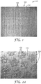
- FIG. 1 An abrasive article according to one exemplary embodiment is shown in FIG. 1 and is designated by the numeral 100.
- the abrasive article 100 includes a backing 102 having a planar major surface 104 approximately parallel to the plane of the page.
- a plurality of discrete clusters 106 are located on the major surface 104 and arranged in a pre-determined pattern.
- the pattern is a two-dimensional ordered array.
- the abrasive article 100 occupies a planar rectangular region corresponding to the patterned region shown in FIG. 1 .
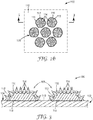
- FIG. 2 shows the pattern of clusters 106 in greater detail.
- the clusters 106 are arranged in a hexagonal array in which each cluster 106 has six equidistant neighbors (excluding edge effects).
- each individual cluster 106 is itself a hexagonal grouping of seven discrete abrasive features 108.
- each of the features 108 is generally circular in shape. However, other shapes such as squares, rectangles, lines and arcs, may also be used. In other embodiments, the features 108 are not clustered.
- the uncoated areas 110 provide open channels allowing swarf, dust, and other debris to be evacuated from the cutting areas where the features 108 contact the workpiece.
- FIG. 2b shows components of the features 108 in further detail and FIG. 3 shows two of the features 108 in cross-section.
- each feature 108 includes a layer of make resin 112 that is preferentially deposited onto the major surface 104 along an interface 118.
- the make resin 112 coats selective areas of the backing 102, thereby forming the base layer for each discrete feature 108, or "island", on the backing 102.
- a plurality of abrasive particles 114 contact the make resin 112 and generally extend in directions away from the major surface 104.
- the particles 114 are generally in registration with the make resin 112 when viewed in directions normal to the plane of the major surface 104.
- the particles 114 as a whole, generally extend across areas of the major surface 104 that are coated by the make resin 112, but do not generally extend across areas of the major surface 104 that are not coated by the make resin 112.
- the particles 114 are at least partially embedded in the make resin 112.
- a size resin 116 contacts both the make resin 112 and the particles 114 and extends on and around both the make resin 112 and the particles 114.
- the size resin 116 is generally in registration with both the make resin 112 and the particles 114 when viewed in directions normal to the plane of the major surface 104.
- the size resin 116 generally extends across areas of the major surface 104 coated by the make resin 112, but does not generally extend across areas of the major surface 104 not coated by the make resin 112.
- the size resin 116 contacts the make resin 112, the abrasive particles 114, and the backing 102.
- essentially all of the abrasive particles 114 are encapsulated by the combination of the make and size resins 112, 116.
- the particles 114 are described here as being “generally in registration” with the make resin 112, it is to be understood that the particles 114 themselves are discrete in nature and have small gaps located between them. Therefore, the particles 114 do not cover the entire area of the underlying make resin 112. Conversely, it is to be understood that while the size resin 116 is “in registration” with make resin 112 and the particles 114, size resin 116 can optionally extend over a slightly oversized area compared with that covered by the make resin 112 and particles 114, as shown in FIG. 2b . In the embodiment shown, the make resin 112 is fully encapsulated by the size resin 116, the particles 114, and the backing 102.
- all of the features 108 on the backing 102 need not be discrete.
- the make resin 112 associated with adjacent features 108 may be in such close proximity that the features 108 contact each other, or become interconnected.
- two or more features 108 may be interconnected with each other within a cluster 106, although the features 108 in separate clusters 106 are not interconnected.
- the backing 102 is uniform in thickness and generally flat.
- the interface 118 where the major surface 104 contacts the make resin 112 is generally coplanar with the areas of the major surface 104 that do not contact the make resin 112 (i.e. uncoated areas 110).
- a backing 102 with a generally uniform thickness is preferred to alleviate stiffness variations and improve conformability of the article 100 to the workpiece. This aspect is further advantageous because it evenly distributes the stress on the backing, which improves durability of the article 100 and extends its operational lifetime.
- the provided abrasive articles present a solution to particular problems with conventional coated abrasive sheets.
- One problem is that conventional abrasive sheets tend to curl in humid environments.
- Another problem is that these coated abrasive sheets often curl immediately when made, a phenomenon known as "intrinsic curl.”
- intrinsic curl To mitigate intrinsic curl, manufacturers can pre-flex these abrasive sheets, but this involves additional processing and still does not effectively address curl that is subsequently induced by the environment.
- the provided abrasive articles have abrasive particles extending across a plurality of islands, or discrete coated regions, along the major surface, while uncoated areas of the major surface are maintained between the islands. It was discovered that when areas of the major surface surrounding these islands do not contact any of the make resin, abrasive particles, or size resin, these abrasive articles display superior resistance to curling when immersed in water or subjected to humid environments.
- these abrasive articles have substantially reduced curl when manufactured and reduce the need for pre-flexing of the abrasive sheets after the make and size resins have been hardened.
- the abrasive articles When tested in accordance with the Dry Curl test (described in the Examples section below), the abrasive articles preferably display a curl radius of at least 20 centimeters, more preferably display a curl radius of at least 50 centimeters, and most preferably display a curl radius of at least 100 centimeters.
- the abrasive articles When tested in accordance with the Wet Curl test (described in the Examples section below), the abrasive articles preferably display a curl radius of at least 2 centimeters, more preferably display a curl radius of at least 5 centimeters, and most preferably display a curl radius of at least 7 centimeters.
- these abrasive articles have been found to display a high degree of flexibility, since a substantial portion of the backing is uncoated.
- the greater flexibility in turn enhances durability. This is particularly shown by its high resistance to tearing and delamination when the abrasive article is subjected to crumpling under wet and dry conditions.
- the abrasive article 100 described above uses a two-dimensional hexagonal coating pattern for the features 108. While the pattern is two-dimensional, the features 108 themselves have some thickness that results in a "feature height" perpendicular to the plane of the backing. However, other coating patterns are also possible, with some offering particular advantages over others.
- the pattern includes a plurality of replicated polygonal clusters and/or features, including ones in the shape of triangles, squares, rhombuses, and the like.
- triangular clusters could be used where each cluster has three or more generally circular abrasive features. Since the abrasive features 108 increase the stiffness of the underlying backing 102 on a local level, the pattern of the abrasive article 100 may be tailored to have enhanced bending flexibility along preferred directions.
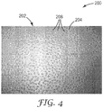
- FIG. 4 shows an abrasive article 200 according to an alternative embodiment displaying a pattern that includes a random array of features.
- the article 200 has a backing 202 with a major surface 204 and an array of discrete and generally circular abrasive features 208 that contact, and extend across, the major surface 204.
- the article 200 differs in that the features 208 are random.
- the features 208 may be semi-random, or have limited aspects that are ordered.
- random patterns are nondirectional within the plane of the major surface of the backing, helping minimize variability in cut performance.
- a random pattern helps avoid creating systematic lines of weakness which may induce curling of the abrasive article along those directions.
- article 200 including the configuration of the abrasive features 208, are analogous to those of article 100 and shall not be repeated here.
- Like reference numerals refer to like elements described previously.
- the abrasive articles 100, 200 preferably have an abrasive coverage (measured as a percentage of the major surface 104) that fits the desired application.
- abrasive coverage advantageously provides greater cutting area between the abrasive particles 114 and the workpiece.
- decreasing abrasive coverage increases the size of the uncoated areas 110. Increasing the size of the uncoated areas 110, in turn, can provide greater space to clear dust and debris and help prevent undesirable loading during an abrading operation.
- low levels of abrasive coverage were nonetheless found to provide very high levels of cut, despite the relatively small cutting area between abrasive and the workpiece.
- fine grade abrasives could be coated onto the backing 102 at less than 50 percent coverage while providing cut performance similar to that of a fully coated sheet.
- coarse grade abrasives could be coated onto the backing 102 at less than 20 percent coverage while providing cut performance similar to that of a fully coated sheet.
- the abrasive particles 114 have an average size (i.e. average particle diameter) ranging from 68 micrometers to 270 micrometers, while the make resin 112 has a coverage that is preferably at most 30 percent, more preferably at most 20 percent, and most preferably at most 10 percent. In other embodiments, the abrasive particles 114 have an average size ranging from 0.5 micrometers to 68 micrometers, while the make resin 112 has a coverage that is preferably at most 70 percent, more preferably at most 60 percent, and most preferably at most 50 percent.
- the backing 102 may be constructed from various materials known in the art for making coated abrasive articles, including sealed coated abrasive backings and porous non-sealed backings.
- the thickness of the backing generally ranges from about 0.02 to about 5 millimeters, more preferably from about 0.05 to about 2.5 millimeters, and most preferably from about 0.1 to about 0.4 millimeters, although thicknesses outside of these ranges may also be useful.
- the backing may be made of any number of various materials including those conventionally used as backings in the manufacture of coated abrasives.
- exemplary flexible backings include polymeric film (including primed films) such as polyolefin film (e.g., polypropylene including biaxially oriented polypropylene, polyester film, polyamide film, cellulose ester film), metal foil, mesh, foam (e.g., natural sponge material or polyurethane foam), cloth (e.g., cloth made from fibers or yarns comprising polyester, nylon, silk, cotton, and/or rayon), scrim, paper, coated paper, vulcanized paper, vulcanized fiber, nonwoven materials, combinations thereof, and treated versions thereof.
- polymeric film including primed films
- polyolefin film e.g., polypropylene including biaxially oriented polypropylene, polyester film, polyamide film, cellulose ester film
- metal foil e.g., natural sponge material or polyurethane foam
- cloth e.g., cloth made from
- the backing may also be a laminate of two materials (e.g., paper/film, cloth/paper, film/cloth). Cloth backings may be woven or stitch bonded.
- the backing is a thin and conformable polymeric film capable of expanding and contracting in transverse (i.e. in-plane) directions during use.
- a strip of such a backing material that is 5.1 centimeters (2 inches) wide, 30.5 centimeters (12 inches) long, and 0.102 millimeters (4 mils) thick and subjected to a 22.2 Newton (5 Pounds-Force) dead load longitudinally stretches at least 0.1%, at least 0.5%, at least 1.0%, at least 1.5%, at least 2.0%.
- the backing strip longitudinally stretches up to 20%, up to 18%, up to 16%, up to 14%, up to 13%, up to 12%, up to 11%, or up to 10%, relative to the original length of the strip.
- the stretching of the backing material can be elastic (with complete spring back), inelastic (with zero spring back), or some mixture of both. This property helps promote contact between the abrasive particles 114 and the underlying substrate, and can be especially beneficial when the substrate includes raised and/or recessed areas.
- Highly conformable polymers that may be used in the backing 102 include certain polyolefin copolymers, polyurethanes, and polyvinyl chloride.
- One particularly preferred polyolefin copolymer is an ethylene-acrylic acid resin (available under the trade designation "PRIMACOR 3440" from Dow Chemical Company, Midland, Michigan).
- ethylene-acrylic acid resin is one layer of a bilayer film in which the other layer is a polyethylene terephthalate (PET) carrier film.
- PET polyethylene terephthalate
- the backing 102 has a modulus of at least 10, at least 12, or at least 15 kilogram-force per square centimeter (kgf/cm 2 ). In some embodiments, the backing 102 has a modulus of up to 200, up to 100, or up to 30 kgf/cm 2 .
- the backing 102 can have a tensile strength at 100% elongation (double its original length) of at least 200, at least 300, or at least 350 kgf/cm 2 .
- the tensile strength of the backing 102 can be up to 900, up to 700, or up to 550 kgf/cm 2 . Backings with these properties can provide various options and advantages, further described in U.S. Patent No. 6,183,677 (Usui et al. ).
- the choice of backing material may depend on the intended application of the coated abrasive article.
- the thickness and smoothness of the backing should also be suitable to provide the desired thickness and smoothness of the coated abrasive article, wherein such characteristics of the coated abrasive article may vary depending, for example, on the intended application or use of the coated abrasive article.
- the backing may, optionally, have at least one of a saturant, a presize layer and/or a backsize layer.
- a saturant typically to seal the backing and/or to protect yarn or fibers in the backing. If the backing is a cloth material, at least one of these materials is typically used.
- the addition of the presize layer or backsize layer may additionally result in a 'smoother' surface on either the front and/or the back side of the backing.
- Other optional layers known in the art may also be used, as described in U.S. Patent No. 5,700,302 (Stoetzel et al. ).
- Suitable abrasive particles for the coated abrasive article 100 include any known abrasive particles or materials useable in abrasive articles.
- useful abrasive particles include fused aluminum oxide, heat treated aluminum oxide, white fused aluminum oxide, black silicon carbide, green silicon carbide, titanium diboride, boron carbide, tungsten carbide, titanium carbide, diamond, cubic boron nitride, garnet, fused alumina zirconia, sol gel abrasive particles, silica, iron oxide, chromia, ceria, zirconia, titania, silicates, metal carbonates (such as calcium carbonate (e.g., chalk, calcite, marl, travertine, marble and limestone), calcium magnesium carbonate, sodium carbonate, magnesium carbonate), silica (e.g., quartz, glass beads, glass bubbles and glass fibers) silicates (e.g., talc, clays, (montmorillonite) felds
- polymeric abrasive particles formed from a thermoplastic material e.g., polycarbonate, polyetherimide, polyester, polyethylene, polysulfone, polystyrene, acrylonitrile-butadienestyrene block copolymer, polypropylene, acetal polymers, polyvinyl chloride, polyurethanes, nylon
- polymeric abrasive particles formed from crosslinked polymers e.g., phenolic resins, aminoplast resins, urethane resins, epoxy resins, melamine-formaldehyde, acrylate resins, acrylated isocyanurate resins, urea-formaldehyde resins, isocyanurate resins, acrylated urethane resins, acrylated epoxy resins
- Other exemplary abrasive particles are described, for example, in U.S. Patent No. 5,549,962 (Holmes et al. ).
- the abrasive particles typically have an average diameter of from about 0.1 to about 270 micrometers, and more desirably from about 1 to about 1300 micrometers. Coating weights for the abrasive particles may depend, for example, on the binder precursor used, the process for applying the abrasive particles, and the size of the abrasive particles, but typically range from about 5 to about 1350 grams per square meter.
- any of a wide selection of make and size resins 112, 116 known in the art may be used to secure the abrasive particles 114 to the backing 102.
- the resins 112, 116 typically include one or more binders having rheological and wetting properties suitable for selective deposition onto a backing.
- binders are formed by curing (e.g., by thermal means, or by using electromagnetic or particulate radiation) a binder precursor.
- first and second binder precursors are known in the abrasive art and include, for example, free-radically polymerizable monomer and/or oligomer, epoxy resins, acrylic resins, epoxy-acrylate oligomers, urethane-acrylate oligomers, urethane resins, phenolic resins, urea-formaldehyde resins, melamine-formaldehyde resins, aminoplast resins, cyanate resins, or combinations thereof.
- Useful binder precursors include thermally curable resins and radiation curable resins, which may be cured, for example, thermally and/or by exposure to radiation.
- Exemplary radiation cured crosslinked acrylate binders are described in U.S. Patent Nos. 4,751,138 (Tumey, et al. ) and 4,828,583 (Oxman, et al. ).
- one or more additional supersize resin layers are applied to the coated abrasive article 100. If a supersize resin is applied, it is preferably in registration with the make resin 112, particles 114, and size resin 116, as viewed in directions normal to the plane of the major surface of the backing.
- the supersize resin may include, for example, grinding aids and anti-loading materials.
- the supersize resin provides enhanced lubricity during an abrading operation.
- any of the make resin, size resin, and supersize resin described above optionally include one or more curatives.
- Curatives include those that are photosensitive or thermally sensitive, and preferably comprise at least one free-radical polymerization initiator and at least one cationic polymerization catalyst, which may be the same or different.
- the binder precursors employed in the present embodiment are preferably photosensitive, and more preferable comprise a photoinitiator and/or a photocatalyst.
- the photoinitiator is capable of at least partially polymerizing (e.g., curing) free-radically polymerizable components of the binder precursor.
- Useful photoinitiators include those known as useful for photocuring free-radically polyfunctional acrylates.
- Exemplary photoinitiators include bis (2,4,6-trimethylbenzoyl)-phenylphosphineoxide, commercially available under the trade designation "IRGACURE 819" from BASF Corporation, Florham Park, New Jersey; benzoin and its derivatives such as alpha-methylbenzoin; alpha-phenylbenzoin; alpha-allylbenzoin; alpha-benzylbenzoin; benzoin ethers such as benzil dimethyl ketal (e.g., as commercially available under the trade designation "IRGACURE 651” from BASF Corporation), benzoin methyl ether, benzoin ethyl ether, benzoin n-butyl ether; acetophenone and its derivative
- Photocatalysts as defined herein are materials that form active species that, if exposed to actinic radiation, are capable of at least partially polymerizing the binder precursor, e.g., an onium salt and/or cationic organometallic salt.
- onium salt photocatalysts comprise iodonium complex salts and/or sulfonium complex salts.
- Aromatic onium salts, useful in practice of the present embodiments, are typically photosensitive only in the ultraviolet region of the spectrum. However, they can be sensitized to the near ultraviolet and the visible range of the spectrum by sensitizers for known photolyzable organic halogen compounds.
- Photoinitiators and photocatalysts useful in the present invention can be present in an amount in the range of 0.01 to 10 weight percent, desirably 0.01 to 5, most desirably 0.1 to 2 weight percent, based on the total amount of photocurable (i.e., crosslinkable by electromagnetic radiation) components of the binder precursor, although amounts outside of these ranges may also be useful.
- the abrasive coatings described above optionally comprise one or more fillers.
- Fillers are typically organic or inorganic particulates dispersed within the resin and may, for example, modify either the binder precursor or the properties of the cured binder, or both, and/or may simply, for example, be used to reduce cost.
- the fillers may be present, for example, to block pores and passages within the backing, to reduce its porosity and provide a surface to which the maker coat will bond effectively.
- the addition of a filler at least up to a certain extent, typically increases the hardness and toughness of the cured binder.
- Inorganic particulate filler commonly has an average particle size ranging from about 1 micrometer to about 100 micrometers, more preferably from about 5 to about 50 micrometers, and sometimes even from about 10 to about 25 micrometers.
- the filler typically has a specific gravity in the range of 1.5 to 4.5, and an average particle size of the filler will preferably be less than the average particle size of the abrasive particles.
- useful fillers include: metal carbonates such as calcium carbonate (in the form of chalk, calcite, marl, travertine, marble or limestone), calcium magnesium carbonate, sodium carbonate, and magnesium carbonate; silicas such as quartz, glass beads, glass bubbles and glass fibers; silicates such as talc, clays, feldspar, mica, calcium silicate, calcium metasilicate, sodium aluminosilicate, sodium-potassium alumina silicate, and sodium silicate ; metal sulfates such as calcium sulfate, barium sulfate, sodium sulfate, aluminum sodium sulfate, and aluminum sulfate ; gypsum; vermiculite ; wood flour ; alumina trihydrate; carbon black ; metal oxides such as calcium oxide (lime), aluminum oxide, titanium dioxide, alumina hydrate, alumina monohydrate; and metal sulfites such as calcium sulfite.
- metal carbonates such as calcium carbonate (in the
- viscosity enhancers or thickeners include viscosity enhancers or thickeners. These additives may be added to a composition of the present embodiment as a cost savings measure or as a processing aid, and may be present in an amount that does not significantly adversely affect properties of a composition so formed. Increase in dispersion viscosity is generally a function of thickener concentration, degree of polymerization, chemical composition or a combination thereof.
- An example of a suitable commercially available thickener is available under the trade designation "CAB-O-SIL M-5" from Cabot Corporation, Boston, Massachusetts.
- anti-foaming agents include "FOAMSTAR S125" from Cognis Corporation, Cincinnati, Ohio.
- Useful process aids include acidic polyester dispersing agents which aid the dispersion of the abrasive particles throughout the polymerizable mixture, such as "BYK W-985" from Byk-Chemie, GmbH, Wesel, Germany.
- the make resin 112 is preferentially applied to the major surface 104 of the backing 102 in a plurality of discrete areas that provide a random or ordered array on the major surface 104 as illustrated, for example, in FIGS. 1 and 4 .
- abrasive particles 114 are applied to the discrete areas of the make resin 112, and the make resin 112 is hardened.
- the mineral can be applied over the entire sheet and then removed from those areas that do not contain the make resin 112.
- a size resin is then preferentially applied over the abrasive particles 114 and the make resin 112 and in contact with backing 102 (but it is not applied to the open areas 110 on the backing 102).
- the size resin 116 is hardened to provide the abrasive article 100.
- the selective application of the make resin 112 and size resin 116 can be achieved using contact methods, non-contact methods, or some combination of both.
- Suitable contact methods include mounting a template, such as a stencil or woven screen, against the backing of the article to mask off areas that are not to be coated.
- Non-contact methods include inkjet-type printing and other technologies capable of selectively coating patterns onto the backing without need for a template.
- Stencil printing uses a frame to support a resin-blocking stencil.
- the stencil forms open areas allowing the transfer of resin to produce a sharply-defined image onto a substrate.
- a roller or squeegee is moved across the screen stencil, forcing or pumping the resin or slurry past the threads of the woven mesh in the open areas.
- Screen printing is also a stencil method of print making in which a design is imposed on a screen of silk or other fine mesh, with blank areas coated with an impermeable substance, and the resin or slurry is forced through the mesh onto the printing surface.
- printing of lower profile and higher fidelity features can be enabled by screen printing. Exemplary uses of screen printing are described in U.S. Patent No. 4,759,982 (Janssen et al. ).
- Yet another applicable contact method uses a combination of screen printing and stencil printing, where a woven mesh is used to support a stencil.
- the stencil includes open areas of mesh through which make resin/size resin can be deposited in the desired pattern of discrete areas onto the backing.
- Another possible contact method for preparing these constructions is a continuous kiss coating operation where the size coat is coated in registration over the abrasive mineral by passing the sheet between a delivery roll and a nip roll, as exemplified in co-pending non-provisional U.S. Patent Publication No. US2012/0000135 (Eilers, et al. ).
- the acrylate make resin can be metered directly onto the delivery roll.
- the final coated material can then be cured to provide the completed article.
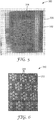
- FIG. 5 shows a stencil 350 for preparing the patterned coated abrasive articles shown in FIGS. 1-3 .
- the stencil 350 includes a generally planar body 352 and a plurality of perforations 354 extending through the body 352.
- a frame 356 surrounds the body on four sides.
- the stencil 350 can be made from a polymer, metal, or ceramic material and is preferably thin. Combinations of metal and woven plastics are also available. These provide enhanced flexibility of the stencil.
- Metal stencils can be etched into a pattern.
- Other suitable stencil materials include polyester films that have a thickness ranging from 1 to 20 mils (0.076 to 0.51 millimeters), more preferably ranging from 3 to 7 mils (0.13 to 0.25 millimeters).
- FIG. 6 shows features of the stencil 350 in greater detail.
- the perforations 354 assume the hexagonal arrangement of clusters and features as described previously for article 100.
- the perforations are created in a precise manner by uploading a suitable digital image into a computer which automatically guides a laser to cut the perforations 354 into the stencil body 352.
- the stencil 350 can be advantageously used to provide precisely defined coating patterns.
- a layer of make resin 112 is selectively applied to the backing 102 by overlaying the stencil 350 on the backing 102 and applying the make resin 112 to the stencil 350.
- the make resin 112 is applied in a single pass using a squeegee, doctor blade, or other blade-like device.
- the stencil 350 is removed prior to hardening of the make resin 112. If so, the viscosity of the make resin 112 is preferably sufficiently high that there is minimal flow out that would distort the originally printed pattern.
- the mineral particles 114 can be deposited on the layer of make resin 112 using a powder coating process or electrostatic coating process.
- electrostatic coating the abrasive particles 114 are applied in an electric field, allowing the particles 114 to be advantageously aligned with their long axes normal to the major surface 104.
- the mineral particles 114 are coated over the entire coated backing 102 and the particles 114 preferentially bond to the areas coated with the tacky make resin 112. After the particles 114 have been preferentially coated onto the make resin 112, the make resin 112 is then partially or fully hardened.
- the hardening step occurs by subjecting the abrasive article 100 at elevated temperatures, exposure to actinic radiation, or a combination of both, to crosslink the make resin 112. Any excess particles 114 can then be removed from the uncoated areas of the backing 102.
- the stencil 350 is again overlaid on the coated backing 102 and positioned with the perforations 354 in registration with the previously hardened make resin 112 and abrasive particles 114.
- the size resin 116 is preferentially applied to the hardened make resin 112 and abrasive particles 114 by applying the size resin 116 to the stencil 350.
- the size resin 116 has an initial viscosity allowing the size resin 116 to flow and encapsulate exposed areas of the abrasive particles 114 and the make resin 112 prior to hardening.
- the stencil 350 is removed prior to hardening of the size resin. Alternatively, the hardening occurs prior to removal of the stencil 350.
- the size resin 116 is hardened to provide the completed abrasive article 100.
- each of the techniques described can be used to create a patterned coated abrasive where the pattern can range from highly random to one which is tightly controlled and predictable. Exemplary coating methods are described in the subsections below.
- the dot size and degree of coalescence can be controlled by several factors such as the air pressure, the nozzle size and geometry, the viscosity of the coating and the distance of the spray from the backing 102.
- the resulting spray pattern can be distinguished from the random dot pattern in the embodiment of FIG. 4 in that a spray-coated pattern is not pre-determined. Since no template is used, each coated abrasive article presents a unique two-dimensional configuration of dot sizes and distributions. Subsequent manufacturing steps also do not require a template.
- abrasive particles 114 are implanted into the make resin 112 by electrostatic coating such that the particles are at least partially embedded in the make layer.
- the size resin 116 can then be deposited in registration with the particles 114 and/or make resin 112 using, for example, the continuous kiss coating operation previously described.
- the entire backing 102 could be made from a low surface energy material.
- a thin layer of a low surface energy material could be applied to the face of a conventional backing material.
- Low surface energy materials which include fluorinated polymers, silicones, and certain polyolefins, can interact with liquids through dispersion (e.g. van der Waals) forces.
- the make resin 112 can spontaneously "bead," or de-wet, from the low surface energy surface. In this manner, discrete islands of make resin 112 can be uniformly distributed across the backing 102 and then coated with the abrasive particles 114 and size resin 116 using techniques already described. Registration to the make resin 112 can be achieved, for example, by a kiss coating process or by the preferential wetting of the size resin 116 on the islands of make resin 112.
- the make resin 112 pattern can be facilitated by selective placement of a chemically dissimilar surface along the plane of the backing, thereby providing a chemically patterned surface.
- Chemical patterning can be achieved by placing a low energy surface pattern onto a high energy surface or, conversely, by placing a high energy surface pattern onto a low energy surface. This can be accomplished using any of various surface modification methods known in the art. Exemplary methods of surface treatment include, for example, corona treatment as described in U.S. Patent Publication No. 2007/0231495 (Ciliske et al. ), 2007/0234954 (Ciliske et al. ), and U.S. Patent No. 6,352,758 (Huang et al.
- a patterned layer could also be facilitated, for example, by mechanically abrading or embossing the backing. These methods are described in detail in U.S. Patent No. 4,877,657 (Yaver ). As another possibility, a low surface energy backing may be used in combination with the spray application concept described above.
- Coating methods may also include methods in which the resin is deposited in the solid state. This can be accomplished, for example, by powder coating the backing 102 with suitably sized polymeric beads.
- the polymeric beads could be made from polyamide, epoxy, or some other make resin 112 and have a size distribution enabling the beads to be evenly distributed across the coated surface.
- heat is then applied to partially or fully melt the polymeric beads and form discrete islands of make resin 112. While the resin is tacky, the resin islands can be coated with a suitable abrasive particles 114 and the resin allowed to harden.
- the abrasive-coated regions are then preferentially coated with the size resin 116 using, for example, a continuous kiss coating process.
- a surface modified backing as described above could be used to avoid coalescence of the resin islands during coating processes.
- Powder coating offers notable advantages, including the elimination of volatile organic compound (VOC) emissions, ability to easily recycle overspray, and general reduction of hazardous waste produced in the manufacturing process.
- VOC volatile organic compound
- the abrasive articles 100, 200 may include one or more additional features that further enhance ease of use, performance or durability.
- the articles optionally include a plurality of dust extraction holes that are connected to a source of vacuum to remove dust and debris from the major surface of the abrasive articles.
- the backing 102, 202 may include a fibrous material, such as a scrim or nonwoven material, facing the opposing direction from the major surface 104, 204.
- the fibrous material can facilitate coupling the article 100, 200 to a power tool.
- the backing 102, 202 includes one-half of a hook and loop attachment system, the other half being disposed on a plate affixed to the power tool.
- a pressure sensitive adhesive may be used for this purpose.
- Such an attachment system secures the article 100, 200 to the power tool while allowing convenient replacement of the article 100, 200 between abrading operations.
- CM-5 A fumed silica, obtained under the trade designation "CAB-O-SIL M-5" from Cabot Corporation, Boston, Massachusetts.
- CPI-6976 A triarylsulfonium hexafluoroantimonate/propylene carbonate photoinitiator, obtained under the trade designation "CYRACURE CPI 6976" from Dow Chemical Company, Midland, Michigan.
- CWT A C-weight olive brown paper, obtained from Wausau Paper Company, Wausau, Wisconsin, subsequently saturated with a styrene-butadiene rubber, in order to make it waterproof.
- D-1173 A ⁇ -Hydroxyketone photoinitiator, obtained under the trade designation "DAROCUR 1173" from BASF Corporation, Florham Park, New Jersey.
- EPON-828 A difunctional bisphenol-A epoxy/epichlorohydrin derived resin having an epoxy equivalent wt. of 185-192, obtained under the trade designation "EPON 828" from Hexion Specialty Chemicals, Columbus, Ohio.
- FEPA P150 A 150 grade silicon carbide mineral, obtained from UK Abrasives, 3045 MacArthur Blvd., Northbrook, Illinois.
- GC-80 An 80 grade silicon carbide mineral, obtained under the trade name "CARBOREX C-5-80" from Washington Mills Electro Minerals Corporation.
- a bis-acyl phosphine photoinitiator obtained under the trade designation "IRGACURE 819" from BASF Corporation.
- MX-10 A sodium-potassium alumina silicate filler, obtained under the trade designation "MINEX 10" from The Cary Company, Addison, Illinois.
- SR-351 trimethylol propane triacrylate, available under the trade designation "SR351" from Sartomer Company, LLC.
- UVR-6110 3,4-epoxy cyclohexylmethyl-3,4-epoxy cyclohexylcarboxylate, obtained from Daicel Chemical Industries, Ltd., Tokyo, Japan.
- a 4.5 by 5.5 inch (11.4 by 14.0 cm) sample sheet was conditioned at 90°F (32.2°C) and 90% relative humidity for 4 hours, after which the 5.5 inch (14.0 cm) edge was centered perpendicularly on an aluminum plate having a series of arcs marked thereon.
- the amount of curl reported corresponds to the radius of the arc traced by the curled sample sheet, that is, the larger the number, the flatter the sample.
- Coated abrasives were laminated to a dual sided adhesive film, and die cut into 4-inch (10.2 cm) diameter discs.
- the laminated coated abrasive was secured to the driven plate of a Schiefer Abrasion Tester, obtained from Frazier Precision Co., Gaithersburg, Maryland, which had been plumbed for wet testing.
- Disc shaped cellulose acetate butyrate (CAB) acrylic plastic workpieces, 4-inch (10.2 cm) outside diameter by 1.27 cm thick, available under the trade designation "POLYCAST" were obtained from Preco Laser, Somerset,Wisconsin.
- the initial weight of each workpiece was recorded prior to mounting on the workpiece holder of the Schiefer tester.
- the water flow rate was set to 60 grams per minute.
- a 14 pound (6.36 kg) weight was placed on the abrasion tester weight platform and the mounted abrasive specimen lowered onto the workpiece and the machine turned on. The machine was set to run for 500 cycles and then automatically stop. After each 500 cycles of the test, the workpiece was rinsed with water, dried and weighed. The cumulative cut for each 500-cycle test was the difference between the initial weight and the weight following each test, and is reported as the average value of 4 measurements.
- the surface finish of a workpiece is defined by Rz and Ra.
- Rz is determined by calculating the arithmetic average of the magnitude of the departure (or distance) of the five tallest peaks of the profile from the meanline and by calculating the average of the magnitude of the departure (or distance) of the five lowest valleys of the profile from its meanline. These two averages are then added together to determine Rz.
- Ra is the arithmetic mean of the magnitude of the departure (or distance) of the profile from its meanline. Both Rz and Ra were measured in three places on each of four replicates corresponding to four cut tests using a profilometer, available under the trade designation "SURTRONIC 25 PROFILOMETER" from Taylor Hobson, Inc., Sheffield, England. The length of scan was 0.03 inches (0.0762 centimeters).
- EPON-828 400.0 grams EPON-828, 300.0 grams UVR-6110, and 300.0 grams SR-351 were charged into a 16 oz. (0.47 liter) black plastic container and dispersed in the resin for 5 minutes at 70°F (21.1°C) using the high speed mixer. To that mixture 30.0 grams CPI-6976 and 10.0 grams D-1173 were added and dispersed until homogeneous (approximately 10 minutes).
- the stencil was taped into the screen frame of a screen printer, model number "AT-1200H/E” from ATMA Champ Ent. Corp., Taipei, Taiwan.
- a film backing was prepared by extruding 4 mil (101.6 ⁇ m) ethylene acrylic acid (EAA) resin, obtained under the trade designation "PRIMACOR 3440” from Dow Chemical Company, Midland, Michigan, onto a 2 mil (50.8 ⁇ m) polyethylene teraphthalate (PET) carrier and cut into a 12 inch by 20 inch sheet.
- PET side of the film backing was then taped to a 12 inch by 20.25 inch (30.48 by 51.44 cm) steel panel, and the panel secured in registration within the screen printer.
- GC-80 mineral was evenly spread over a 10 inch by 18 inch (25.4 by 45.72 cm) metal plate to produce a mineral bed.
- the acrylate coated surface of the steel panel-film assembly was then suspended one inch (2.54 cm) above the mineral bed.
- the mineral was then electrostatically transferred to the acrylate coated surface by applying 10-20 kilovolts DC across the metal plate and the steel panel-film assembly.
- the steel panel-coated film assembly was passed through a single D-bulb UV processor, model "DRS-111", obtained from Fusion UV Systems, Inc., Maryland, at 37.2 ft/min (11.3 m/min.), corresponding to a dose of 625 mJ/cm 2 .
- Residual mineral not bonded to the acrylate make resin was removed by lightly brushing with a paint brush and the assembly reinserted into the screen printer in the same position as before.
- Approximately 75 grams of the epoxy acrylate size coat was spread over the stencil at 70°F (21.1°C) using a urethane squeegee, then stencil printed onto the film backing, after which the steel panel-coated film assembly was immediately removed from the screen printer and passed through the UV processor at 37.2 ft/min (11.3 m/min.), corresponding to a dose of 625 mJ/cm 2 .
- the EAA/PET film backing was removed from the steel panel and PET carrier rapidly stripped off the coated EAA film.
- the coated EAA film was then rubbed under light hand pressure for 60 seconds against a portion of an 18 inch by 24 inch (45.7 cm by 61 cm) black painted cold roll steel test panel having "RK8148" type clear coat, obtained from ACT Laboratories, Inc., Hillsdale, Michigan. Approximately 0.09 grams of material was removed.
- the framed mesh was mounted onto the screen printer and a 12 inch by 20 inch (30.48 by 50.8 cm) sheet of CWT paper was taped to the printer backing plate, and the plate secured in registration within the screen printer.
- the backing plate and coated paper assembly was immediately removed from the screen printer and FEPA-P150 mineral was electrostatically applied to the acrylate make resin using the laboratory electrostatic coater.
- the sample was then passed through the UV processor at 16.4 ft/min (5.0 m/min.), corresponding to a total dose of 2,814 mJ/cm 2 , after which residual mineral was removed using a workshop vacuum with a bristle attachment, model "RIDGID WD14500", obtained from Emerson Electrical Co., St. Louis, Missouri.
- the sample was removed from the printer backing plate, taped to a carrier web and the epoxy acrylate size coat resin applied in a discontinuous layer via a flexographic roll coating operation using an anilox-flexographic-impression nip roll coater.
- the coated paper was cured by passing once through the UV processor at 16.4 ft/min (5.0 m/min.), corresponding to a total dose of approximately 2,814 mJ/cm 2 .
- the total coating weight on the paper was determined to be 78.79 g/m 2 .
Claims (13)
- Ein Schleifgegenstand (100, 200), aufweisend:einen flexiblen Träger (102, 202) mit einer Hauptoberfläche (104, 204), aufweisend ein anpassungsfähiges Polymer, das in der Lage ist, sich in Querrichtungen auszudehnen und zusammenzuziehen,ein Bindemittelharz (112), das die Hauptoberfläche kontaktiert und sich über die Hauptoberfläche in einem vorbestimmten Muster erstreckt;Schleifteilchen (114), die das Bindemittelharz kontaktieren und sich, betrachtet in Richtungen, die zu der Ebene der Hauptoberfläche senkrecht sind, im Allgemeinen mit dem Bindemittelharz decken; undein Leimharz (116), das sowohl die Schleifteilchen als auch das Bindemittelharz kontaktiert, wobei sich das Leimharz, betrachtet in Richtungen, die zu der Ebene der Hauptoberfläche senkrecht sind, im Allgemeinen sowohl mit den Schleifteilchen als auch dem Bindemittelharz deckt, wobei Bereiche der Hauptoberfläche, die das Bindemittelharz kontaktieren, im Allgemeinen koplanar mit Bereichen der Hauptoberfläche sind, die das Bindemittelharz nicht kontaktieren, dadurch gekennzeichnet, dass sich ein Streifen des anpassungsfähigen Polymers, der 5,1 cm breit, 30,5 cm lang und 0,102 mm dick ist, in Längsrichtung um mindestens 3,0 % dehnt, wenn er einer Eigenlast von 22,2 N ausgesetzt wird.
- Ein Schleifgegenstand (100, 200), aufweisend:einen flexiblen Träger (102, 202) mit einer Hauptoberfläche (104, 204), aufweisend ein anpassungsfähiges Polymer, das in der Lage ist, sich in Querrichtungen auszudehnen und zusammenzuziehen;ein Bindemittelharz (112), das einen Abschnitt der Hauptoberfläche kontaktiert;Schleifteilchen (114), die das Bindemittelharz kontaktieren und sich, betrachtet in Richtungen, die zu der Ebene der Hauptoberfläche senkrecht sind, im Allgemeinen mit dem Bindemittelharz decken; undein Leimharz (116), das sowohl die Schleifteilchen als auch das Bindemittelharz kontaktiert und sich, betrachtet in Richtungen, die zu der Ebene der Hauptoberfläche senkrecht sind, im Allgemeinen sowohl mit den Schleifteilchen als auch dem Bindemittelharz deckt, dadurch gekennzeichnet, dass das Bindemittelharz eine Abdeckung von höchstens 30 % aufweist und dadurch, dass sich ein Streifen des anpassungsfähigen Polymers, der 5,1 cm breit, 30,5 cm lang und 0,102 mm dick ist, in Längsrichtung um mindestens 3,0 % dehnt, wenn er einer Eigenlast von 22,2 N ausgesetzt wird.
- Der Schleifgegenstand (100, 200) nach Anspruch 2, wobei das Bindemittelharz (112) eine Abdeckung von höchstens 10 Prozent aufweist.
- Der Schleifgegenstand (100, 200) nach Anspruch 1 oder 2, wobei das anpassungsfähige Polymer ausgewählt ist aus einem Polyolefin-Copolymer, Polyurethan oder Polyvinylchlorid.
- Der Schleifgegenstand (100, 200) nach Anspruch 4, wobei das anpassungsfähige Polymer ein Polyolefin-Copolymer ist, das Polyethylen-Acrylsäure aufweist.
- Der Schleifgegenstand (100, 200) nach einem der vorstehenden Ansprüche, ferner aufweisend ein Superleimharz, welches das Leimharz (116) kontaktiert und sich, betrachtet in Richtungen, die zu der Ebene der Hauptoberfläche (104, 204) senkrecht sind, im Allgemeinen mit dem Leimharz deckt, wobei das Superleimharz eine verbesserte Schmierfähigkeit bereitstellt.
- Der Schleifgegenstand (100, 200) nach einem der Ansprüche 1, 2 oder 4 bis 6, wobei die Schleifteilchen (114) eine Durchschnittsgröße im Bereich von 68 Mikrometern bis 270 Mikrometern aufweisen und das Bindemittelharz (112) eine Abdeckung von höchstens 30 Prozent aufweist.
- Der Schleifgegenstand (100, 200) nach einem der Ansprüche 1 und 4 bis 6, wobei die Schleifteilchen (114) eine Durchschnittsgröße im Bereich von 0,5 Mikrometern bis 68 Mikrometern aufweisen und das Bindemittelharz (112) eine Abdeckung von höchstens 70 Prozent aufweist.
- Der Schleifgegenstand (100, 200) nach einem der Ansprüche 1 und 4 bis 8, wobei das vorbestimmte Muster eine Mehrzahl von replizierten polygonalen Clustern (106) aufweist.
- Der Schleifgegenstand (100, 200) nach Anspruch 9, wobei jeder polygonale Cluster (106) drei oder mehr im Allgemeinen kreisförmige Merkmale (108, 208) aufweist.
- Der Schleifgegenstand (100, 200) nach Anspruch 9 oder 10, wobei jeder polygonale Cluster (106) ein hexagonales Cluster von sieben im Allgemeinen kreisförmigen Merkmalen ist.
- Der Schleifgegenstand (100, 200) nach einem der Ansprüche 1 und 4 bis 8, wobei das vorbestimmte Muster eine zufällige Anordnung von im Allgemeinen kreisförmigen Merkmalen (108, 208) ist.
- Der Schleifgegenstand (100, 200) nach einem der vorstehenden Ansprüche, wobei im Wesentlichen alle Schleifteilchen (114) von der Kombination des Bindemittel- (112) und des Leimharzes (116) eingekapselt sind.
Applications Claiming Priority (2)
| Application Number | Priority Date | Filing Date | Title |
|---|---|---|---|
| US201161581443P | 2011-12-29 | 2011-12-29 | |
| PCT/US2012/070485 WO2013101575A2 (en) | 2011-12-29 | 2012-12-19 | Coated abrasive article |
Publications (2)
| Publication Number | Publication Date |
|---|---|
| EP2797717A2 EP2797717A2 (de) | 2014-11-05 |
| EP2797717B1 true EP2797717B1 (de) | 2021-11-24 |
Family
ID=47520291
Family Applications (1)
| Application Number | Title | Priority Date | Filing Date |
|---|---|---|---|
| EP12812478.1A Active EP2797717B1 (de) | 2011-12-29 | 2012-12-19 | Beschichteter schleifartikel und verfahren zu seiner herstellung |
Country Status (7)
| Country | Link |
|---|---|
| US (1) | US9630297B2 (de) |
| EP (1) | EP2797717B1 (de) |
| JP (2) | JP6382109B2 (de) |
| CN (1) | CN104039508B (de) |
| BR (1) | BR112014016237A8 (de) |
| RU (1) | RU2605721C2 (de) |
| WO (1) | WO2013101575A2 (de) |
Families Citing this family (44)
| Publication number | Priority date | Publication date | Assignee | Title |
|---|---|---|---|---|
| KR102187425B1 (ko) | 2011-12-30 | 2020-12-09 | 생-고뱅 세라믹스 앤드 플라스틱스, 인코포레이티드 | 형상화 연마입자 및 이의 형성방법 |
| KR101681526B1 (ko) | 2011-12-30 | 2016-12-01 | 생-고뱅 세라믹스 앤드 플라스틱스, 인코포레이티드 | 복합 형상화 연마입자들 및 이의 형성방법 |
| BR112014017050B1 (pt) | 2012-01-10 | 2021-05-11 | Saint-Gobain Ceramics & Plastics, Inc. | partícula abrasiva moldada |
| CN104411459B (zh) | 2012-06-29 | 2018-06-15 | 圣戈本陶瓷及塑料股份有限公司 | 具有特定形状的磨粒和形成这种粒子的方法 |
| EP2869969A2 (de) * | 2012-07-06 | 2015-05-13 | 3M Innovative Properties Company | Beschichteter schleifartikel |
| US9440332B2 (en) | 2012-10-15 | 2016-09-13 | Saint-Gobain Abrasives, Inc. | Abrasive particles having particular shapes and methods of forming such particles |
| SG11201506702PA (en) | 2013-02-26 | 2015-09-29 | Kwh Mirka Ltd | A method to provide an abrasive product surface and abrasive products thereof |
| PL2961571T3 (pl) * | 2013-02-26 | 2019-10-31 | Kwh Mirka Ltd | Sposób dostarczania wyrobu ściernego i jego wyrobów ściernych |
| WO2014161001A1 (en) | 2013-03-29 | 2014-10-02 | Saint-Gobain Abrasives, Inc. | Abrasive particles having particular shapes and methods of forming such particles |
| CN104442611A (zh) * | 2013-09-20 | 2015-03-25 | 西川橡胶工业股份有限公司 | 防水用密封件以及使用了该防水用密封件的密封方法 |
| RU2643004C2 (ru) | 2013-09-30 | 2018-01-29 | Сен-Гобен Серэмикс Энд Пластикс, Инк. | Формованные абразивные частицы и способы их получения |
| CN104726061A (zh) * | 2013-12-19 | 2015-06-24 | 3M创新有限公司 | 磨料、研磨件及其制备方法 |
| KR101870617B1 (ko) | 2013-12-31 | 2018-06-26 | 생-고뱅 어브레이시브즈, 인코포레이티드 | 형상화 연마 입자들을 포함하는 연마 물품 |
| US9771507B2 (en) | 2014-01-31 | 2017-09-26 | Saint-Gobain Ceramics & Plastics, Inc. | Shaped abrasive particle including dopant material and method of forming same |
| US10435827B2 (en) | 2014-02-17 | 2019-10-08 | 3M Innovative Properties Company | Scouring article and methods of making and using |
| CN106457522B (zh) | 2014-04-14 | 2020-03-24 | 圣戈本陶瓷及塑料股份有限公司 | 包括成形磨粒的研磨制品 |
| US9914864B2 (en) | 2014-12-23 | 2018-03-13 | Saint-Gobain Ceramics & Plastics, Inc. | Shaped abrasive particles and method of forming same |
| EP3277459B1 (de) | 2015-03-31 | 2023-08-16 | Saint-Gobain Abrasives, Inc. | Feste schleifartikel und verfahren zur formung davon |
| TWI634200B (zh) | 2015-03-31 | 2018-09-01 | 聖高拜磨料有限公司 | 固定磨料物品及其形成方法 |
| US10687613B2 (en) | 2015-05-07 | 2020-06-23 | Craig R. Smith | Rotary cleaning tool for commode surfaces |
| WO2016201104A1 (en) | 2015-06-11 | 2016-12-15 | Saint-Gobain Ceramics & Plastics, Inc. | Abrasive article including shaped abrasive particles |
| EP3356084A4 (de) | 2015-10-02 | 2020-02-12 | 3M Innovative Properties Company | Trockenwandschleifblock und verfahren zur verwendung |
| EP3397428A1 (de) | 2015-12-29 | 2018-11-07 | 3M Innovative Properties Company | Schleifartikel und verfahren zur herstellung davon |
| WO2017197002A1 (en) | 2016-05-10 | 2017-11-16 | Saint-Gobain Ceramics & Plastics, Inc. | Abrasive particles and methods of forming same |
| KR102243356B1 (ko) | 2016-05-10 | 2021-04-23 | 생-고뱅 세라믹스 앤드 플라스틱스, 인코포레이티드 | 연마 입자 및 이의 형성 방법 |
| EP4349896A2 (de) | 2016-09-29 | 2024-04-10 | Saint-Gobain Abrasives, Inc. | Feste schleifartikel und verfahren zur formung davon |
| JP2020513337A (ja) * | 2016-12-09 | 2020-05-14 | スリーエム イノベイティブ プロパティズ カンパニー | 研磨物品及び研磨方法 |
| US10759024B2 (en) | 2017-01-31 | 2020-09-01 | Saint-Gobain Ceramics & Plastics, Inc. | Abrasive article including shaped abrasive particles |
| US10563105B2 (en) | 2017-01-31 | 2020-02-18 | Saint-Gobain Ceramics & Plastics, Inc. | Abrasive article including shaped abrasive particles |
| CN107225516B (zh) * | 2017-06-16 | 2019-07-16 | 东莞金太阳研磨股份有限公司 | 一种柔性3d磨具的制造方法 |
| US10865148B2 (en) | 2017-06-21 | 2020-12-15 | Saint-Gobain Ceramics & Plastics, Inc. | Particulate materials and methods of forming same |
| US20210162559A1 (en) * | 2017-07-11 | 2021-06-03 | 3M Innovative Properties Company | Abrasive articles including conformable coatings and polishing system therefrom |
| USD850041S1 (en) | 2017-07-31 | 2019-05-28 | 3M Innovative Properties Company | Scouring pad |
| CN107378810A (zh) * | 2017-08-01 | 2017-11-24 | 华侨大学 | 一种在位雕刻实现磨粒图案分布砂轮的制作装置 |
| CN107378811A (zh) * | 2017-08-01 | 2017-11-24 | 华侨大学 | 一种在位镂空固化实现磨粒图案分布磨轮的制作装置 |
| CN107457715A (zh) * | 2017-08-01 | 2017-12-12 | 华侨大学 | 一种磨粒图案分布砂轮的制作方法及制作装置 |
| EP3720654A1 (de) | 2017-12-08 | 2020-10-14 | 3M Innovative Properties Company | Schleifartikel |
| CN110549258B (zh) * | 2018-06-01 | 2020-09-11 | 东莞市中微纳米科技有限公司 | 一种抛光片及其制备方法 |
| CN110774186B (zh) * | 2018-07-30 | 2022-03-08 | 江苏华东砂轮有限公司 | 用于非平面结构工件抛光的涂附磨具及其制备方法 |
| BR112021015764A2 (pt) | 2019-02-11 | 2021-10-05 | 3M Innovative Properties Company | Artigo abrasivo |
| CN114901430A (zh) * | 2019-12-09 | 2022-08-12 | 3M创新有限公司 | 带涂层磨料制品及制备带涂层磨料制品的方法 |
| EP4081369A4 (de) | 2019-12-27 | 2024-04-10 | Saint Gobain Ceramics | Schleifartikel und verfahren zur formung davon |
| US20210197342A1 (en) * | 2019-12-31 | 2021-07-01 | Saint-Gobain Abrasives, Inc. | Rigid backsize to prevent fiber disc curling |
| DE102021215122A1 (de) * | 2021-12-30 | 2023-07-06 | Robert Bosch Gesellschaft mit beschränkter Haftung | Schleifmittel |
Family Cites Families (66)
| Publication number | Priority date | Publication date | Assignee | Title |
|---|---|---|---|---|
| US794495A (en) | 1902-04-30 | 1905-07-11 | George Gorton | Abrading-surface. |
| US2334642A (en) | 1942-08-03 | 1943-11-16 | Ted C Beshear | Abrasive tool |
| BE530127A (de) | 1953-11-25 | |||
| US2863306A (en) | 1956-04-27 | 1958-12-09 | Coro Inc | Combination brooch and earring with cover means for the brooch pin |
| US2907146A (en) | 1957-05-21 | 1959-10-06 | Milwaukee Motive Mfg Co | Grinding discs |
| US3605349A (en) | 1969-05-08 | 1971-09-20 | Frederick B Anthon | Abrasive finishing article |
| US3991527A (en) | 1975-07-10 | 1976-11-16 | Bates Abrasive Products, Inc. | Coated abrasive disc |
| EP0004454A3 (de) | 1978-03-23 | 1979-10-31 | Robert Michael Barron | Beschichtete Schleifwerkzeuge |
| DE2918103C2 (de) | 1979-05-04 | 1985-12-05 | Sia Schweizer Schmirgel- & Schleifindustrie Ag, Frauenfeld | Verfahren zum Auftragen eines Grundbindemittels und Vorrichtung zur Durchführung desselben |
| US4594262A (en) | 1984-07-05 | 1986-06-10 | Minnesota Mining And Manufacturing Company | Electron beam adhesion-promoting treatment of polyester film base |
| US4759982A (en) | 1986-12-12 | 1988-07-26 | Minnesota Mining And Manufacturing Company | Transfer graphic article with rounded and sealed edges and method for making same |
| US4751138A (en) | 1986-08-11 | 1988-06-14 | Minnesota Mining And Manufacturing Company | Coated abrasive having radiation curable binder |
| US4828583A (en) | 1987-04-02 | 1989-05-09 | Minnesota Mining And Manufacturing Company | Coated abrasive binder containing ternary photoinitiator system |
| US4930266A (en) | 1988-02-26 | 1990-06-05 | Minnesota Mining And Manufacturing Company | Abrasive sheeting having individually positioned abrasive granules |
| WO1990000105A1 (en) * | 1988-06-30 | 1990-01-11 | Mitchell, Richard, J. | Abrasive product with reduced particle concentration |
| US4925457B1 (en) | 1989-01-30 | 1995-09-26 | Ultimate Abrasive Syst Inc | Method for making an abrasive tool |
| US4877657A (en) | 1989-02-06 | 1989-10-31 | The D.L. Auld Company | Decorative trim strip with enhanced depth of vision |
| US5014468A (en) | 1989-05-05 | 1991-05-14 | Norton Company | Patterned coated abrasive for fine surface finishing |
| JPH0788903B2 (ja) | 1989-05-25 | 1995-09-27 | 東洋ゴム工業株式会社 | 凹凸多溝構造を有するダイヤフラムの製造方法 |
| US4988554A (en) | 1989-06-23 | 1991-01-29 | Minnesota Mining And Manufacturing Company | Abrasive article coated with a lithium salt of a fatty acid |
| US5067400A (en) | 1990-01-25 | 1991-11-26 | Bezella Gary L | Screen printing with an abrasive ink |
| JP3000377B2 (ja) | 1990-06-27 | 2000-01-17 | 春光 安田 | 研磨布紙 |
| JP3008118B2 (ja) | 1990-06-27 | 2000-02-14 | 春光 安田 | 研磨布紙 |
| JP3008119B2 (ja) | 1990-06-27 | 2000-02-14 | 春光 安田 | 研磨布紙 |
| US5437754A (en) | 1992-01-13 | 1995-08-01 | Minnesota Mining And Manufacturing Company | Abrasive article having precise lateral spacing between abrasive composite members |
| JPH08507257A (ja) * | 1993-03-12 | 1996-08-06 | ミネソタ・マイニング・アンド・マニュファクチュアリング・カンパニー | 石材を研磨する方法および物品 |
| US5549962A (en) | 1993-06-30 | 1996-08-27 | Minnesota Mining And Manufacturing Company | Precisely shaped particles and method of making the same |
| JP2808261B2 (ja) | 1995-10-31 | 1998-10-08 | 株式会社コバックス | 研磨シートおよびその製造方法 |
| DE29520566U1 (de) | 1995-12-29 | 1996-02-22 | Joest Peter | Direkt oder indirekt mit einer Maschine oder einem manuell betreibbaren Schleifmittelhalter adaptierbarer Schleifkörper sowie ein hierfür geeigneter Adapter |
| US5700302A (en) | 1996-03-15 | 1997-12-23 | Minnesota Mining And Manufacturing Company | Radiation curable abrasive article with tie coat and method |
| US5891967A (en) | 1996-04-25 | 1999-04-06 | Minnesota Mining & Manufacturing Company | Flame-treating process |
| US5900317A (en) | 1996-09-13 | 1999-05-04 | Minnesota Mining & Manufacturing Company | Flame-treating process |
| US5833724A (en) | 1997-01-07 | 1998-11-10 | Norton Company | Structured abrasives with adhered functional powders |
| US5840088A (en) | 1997-01-08 | 1998-11-24 | Norton Company | Rotogravure process for production of patterned abrasive surfaces |
| US6537140B1 (en) | 1997-05-14 | 2003-03-25 | Saint-Gobain Abrasives Technology Company | Patterned abrasive tools |
| US6352758B1 (en) | 1998-05-04 | 2002-03-05 | 3M Innovative Properties Company | Patterned article having alternating hydrophilic and hydrophobic surface regions |
| US6458018B1 (en) * | 1999-04-23 | 2002-10-01 | 3M Innovative Properties Company | Abrasive article suitable for abrading glass and glass ceramic workpieces |
| US6319108B1 (en) * | 1999-07-09 | 2001-11-20 | 3M Innovative Properties Company | Metal bond abrasive article comprising porous ceramic abrasive composites and method of using same to abrade a workpiece |
| US6755720B1 (en) | 1999-07-15 | 2004-06-29 | Noritake Co., Limited | Vitrified bond tool and method of manufacturing the same |
| US6257973B1 (en) | 1999-11-04 | 2001-07-10 | Norton Company | Coated abrasive discs |
| US7632434B2 (en) * | 2000-11-17 | 2009-12-15 | Wayne O. Duescher | Abrasive agglomerate coated raised island articles |
| US8545583B2 (en) | 2000-11-17 | 2013-10-01 | Wayne O. Duescher | Method of forming a flexible abrasive sheet article |
| EP1207015A3 (de) | 2000-11-17 | 2003-07-30 | Keltech Engineering, Inc. | Schleifartikel mit erhobenen Inseln, Anwendungsverfahren und Läppvorrichtung |
| US6599177B2 (en) | 2001-06-25 | 2003-07-29 | Saint-Gobain Abrasives Technology Company | Coated abrasives with indicia |
| US20040180618A1 (en) | 2001-09-03 | 2004-09-16 | Kazuo Suzuki | Sheet-form abrasive with dimples or perforations |
| GB0122153D0 (en) | 2001-09-13 | 2001-10-31 | 3M Innovative Properties Co | Abrasive articles |
| US6758734B2 (en) | 2002-03-18 | 2004-07-06 | 3M Innovative Properties Company | Coated abrasive article |
| US6773474B2 (en) | 2002-04-19 | 2004-08-10 | 3M Innovative Properties Company | Coated abrasive article |
| US7044989B2 (en) | 2002-07-26 | 2006-05-16 | 3M Innovative Properties Company | Abrasive product, method of making and using the same, and apparatus for making the same |
| JP4672968B2 (ja) | 2003-04-23 | 2011-04-20 | キヤノン株式会社 | 撮像装置 |
| BRPI0409667B1 (pt) * | 2003-04-25 | 2014-06-24 | 3M Innovative Properties Co | Material para esfregar, e, método para fabricar o mesmo |
| JP2007536100A (ja) * | 2004-05-03 | 2007-12-13 | スリーエム イノベイティブ プロパティズ カンパニー | ミクロ仕上げ用バックアップシューおよび方法 |
| JP2006136973A (ja) | 2004-11-11 | 2006-06-01 | Noritake Co Ltd | 三次元立体構造の研磨凸部を備えた研磨布紙 |
| US7169029B2 (en) | 2004-12-16 | 2007-01-30 | 3M Innovative Properties Company | Resilient structured sanding article |
| WO2006074058A1 (en) | 2004-12-30 | 2006-07-13 | 3M Innovative Properties Company | Abrasive article and methods of making same |
| AU2006237653B2 (en) * | 2005-04-14 | 2010-05-20 | Saint-Gobain Abrasives, Inc. | Method of forming structured abrasive article |
| US7618306B2 (en) | 2005-09-22 | 2009-11-17 | 3M Innovative Properties Company | Conformable abrasive articles and methods of making and using the same |
| US20070231495A1 (en) | 2006-03-31 | 2007-10-04 | Ciliske Scott L | Method of forming multi-layer films using corona treatments |
| US7707963B2 (en) | 2006-03-31 | 2010-05-04 | 3M Innovative Properties Company | System for forming multi-layer films using corona treatments |
| US7862187B2 (en) | 2006-04-18 | 2011-01-04 | 3M Innovative Properties Company | Microstructured articles comprising nitrogen containing ingredient |
| JP4973349B2 (ja) * | 2007-07-13 | 2012-07-11 | 株式会社コバックス | 研磨物品 |
| CN102863635B (zh) | 2007-08-03 | 2015-03-25 | 圣戈班磨料磨具有限公司 | 具有助黏附层的磨料物品 |
| CN101602190B (zh) * | 2009-07-06 | 2010-09-29 | 苏州远东砂轮有限公司 | 低聚合度全树脂涂附磨具的制造方法 |
| CN101607384B (zh) * | 2009-07-10 | 2010-09-22 | 湖北玉立砂带集团股份有限公司 | Uea116超精密研磨带的制备方法 |
| WO2011087653A1 (en) | 2009-12-22 | 2011-07-21 | 3M Innovative Properties Company | Flexible abrasive article and methods of making |
| EP2588275B1 (de) | 2010-07-02 | 2017-12-27 | 3M Innovative Properties Company | Beschichtete schleifgegenstände |
-
2012
- 2012-12-19 EP EP12812478.1A patent/EP2797717B1/de active Active
- 2012-12-19 RU RU2014125490/02A patent/RU2605721C2/ru not_active IP Right Cessation
- 2012-12-19 CN CN201280064432.8A patent/CN104039508B/zh active Active
- 2012-12-19 US US14/354,947 patent/US9630297B2/en active Active
- 2012-12-19 JP JP2014550343A patent/JP6382109B2/ja active Active
- 2012-12-19 BR BR112014016237A patent/BR112014016237A8/pt not_active Application Discontinuation
- 2012-12-19 WO PCT/US2012/070485 patent/WO2013101575A2/en active Application Filing
-
2017
- 2017-09-08 JP JP2017173503A patent/JP6410904B2/ja active Active
Non-Patent Citations (1)
| Title |
|---|
| None * |
Also Published As
| Publication number | Publication date |
|---|---|
| CN104039508A (zh) | 2014-09-10 |
| EP2797717A2 (de) | 2014-11-05 |
| BR112014016237A8 (pt) | 2017-07-04 |
| BR112014016237A2 (pt) | 2017-06-13 |
| JP2018020436A (ja) | 2018-02-08 |
| JP2015503458A (ja) | 2015-02-02 |
| US20140308884A1 (en) | 2014-10-16 |
| JP6382109B2 (ja) | 2018-08-29 |
| RU2014125490A (ru) | 2016-02-20 |
| JP6410904B2 (ja) | 2018-10-24 |
| US9630297B2 (en) | 2017-04-25 |
| WO2013101575A3 (en) | 2014-03-13 |
| CN104039508B (zh) | 2017-12-12 |
| RU2605721C2 (ru) | 2016-12-27 |
| WO2013101575A2 (en) | 2013-07-04 |
Similar Documents
| Publication | Publication Date | Title |
|---|---|---|
| EP2797717B1 (de) | Beschichteter schleifartikel und verfahren zu seiner herstellung | |
| US9393673B2 (en) | Coated abrasive article | |
| EP2588275B1 (de) | Beschichtete schleifgegenstände | |
| JP2015503458A5 (de) | ||
| EP3137258A1 (de) | Beschichteter schleifartikel | |
| RU2449881C2 (ru) | Тисненое структурированное абразивное изделие и способ его изготовления и применения | |
| KR101429038B1 (ko) | 내구성이 우수한 연마포지 용품 | |
| JP6623153B2 (ja) | 構造化研磨物品並びにその使用方法 | |
| EP3541573A1 (de) | Strukturierter schleifartikel mit merkmalen mit verbesserter struktureller integrität | |
| EP3370918B1 (de) | Beschichteter schleifartikel |
Legal Events
| Date | Code | Title | Description |
|---|---|---|---|
| PUAI | Public reference made under article 153(3) epc to a published international application that has entered the european phase |
Free format text: ORIGINAL CODE: 0009012 |
|
| 17P | Request for examination filed |
Effective date: 20140707 |
|
| AK | Designated contracting states |
Kind code of ref document: A2 Designated state(s): AL AT BE BG CH CY CZ DE DK EE ES FI FR GB GR HR HU IE IS IT LI LT LU LV MC MK MT NL NO PL PT RO RS SE SI SK SM TR |
|
| DAX | Request for extension of the european patent (deleted) | ||
| STAA | Information on the status of an ep patent application or granted ep patent |
Free format text: STATUS: EXAMINATION IS IN PROGRESS |
|
| 17Q | First examination report despatched |
Effective date: 20180605 |
|
| STAA | Information on the status of an ep patent application or granted ep patent |
Free format text: STATUS: EXAMINATION IS IN PROGRESS |
|
| GRAP | Despatch of communication of intention to grant a patent |
Free format text: ORIGINAL CODE: EPIDOSNIGR1 |
|
| STAA | Information on the status of an ep patent application or granted ep patent |
Free format text: STATUS: GRANT OF PATENT IS INTENDED |
|
| INTG | Intention to grant announced |
Effective date: 20210608 |
|
| GRAS | Grant fee paid |
Free format text: ORIGINAL CODE: EPIDOSNIGR3 |
|
| GRAA | (expected) grant |
Free format text: ORIGINAL CODE: 0009210 |
|
| STAA | Information on the status of an ep patent application or granted ep patent |
Free format text: STATUS: THE PATENT HAS BEEN GRANTED |
|
| AK | Designated contracting states |
Kind code of ref document: B1 Designated state(s): AL AT BE BG CH CY CZ DE DK EE ES FI FR GB GR HR HU IE IS IT LI LT LU LV MC MK MT NL NO PL PT RO RS SE SI SK SM TR |
|
| REG | Reference to a national code |
Ref country code: GB Ref legal event code: FG4D |
|
| REG | Reference to a national code |
Ref country code: AT Ref legal event code: REF Ref document number: 1449491 Country of ref document: AT Kind code of ref document: T Effective date: 20211215 |
|
| REG | Reference to a national code |
Ref country code: DE Ref legal event code: R096 Ref document number: 602012077226 Country of ref document: DE |
|
| REG | Reference to a national code |
Ref country code: IE Ref legal event code: FG4D |
|
| REG | Reference to a national code |
Ref country code: FI Ref legal event code: FGE |
|
| REG | Reference to a national code |
Ref country code: LT Ref legal event code: MG9D |
|
| REG | Reference to a national code |
Ref country code: NL Ref legal event code: MP Effective date: 20211124 |
|
| REG | Reference to a national code |
Ref country code: AT Ref legal event code: MK05 Ref document number: 1449491 Country of ref document: AT Kind code of ref document: T Effective date: 20211124 |
|
| PG25 | Lapsed in a contracting state [announced via postgrant information from national office to epo] |
Ref country code: RS Free format text: LAPSE BECAUSE OF FAILURE TO SUBMIT A TRANSLATION OF THE DESCRIPTION OR TO PAY THE FEE WITHIN THE PRESCRIBED TIME-LIMIT Effective date: 20211124 Ref country code: LT Free format text: LAPSE BECAUSE OF FAILURE TO SUBMIT A TRANSLATION OF THE DESCRIPTION OR TO PAY THE FEE WITHIN THE PRESCRIBED TIME-LIMIT Effective date: 20211124 Ref country code: BG Free format text: LAPSE BECAUSE OF FAILURE TO SUBMIT A TRANSLATION OF THE DESCRIPTION OR TO PAY THE FEE WITHIN THE PRESCRIBED TIME-LIMIT Effective date: 20220224 Ref country code: AT Free format text: LAPSE BECAUSE OF FAILURE TO SUBMIT A TRANSLATION OF THE DESCRIPTION OR TO PAY THE FEE WITHIN THE PRESCRIBED TIME-LIMIT Effective date: 20211124 |
|
| PG25 | Lapsed in a contracting state [announced via postgrant information from national office to epo] |
Ref country code: IS Free format text: LAPSE BECAUSE OF FAILURE TO SUBMIT A TRANSLATION OF THE DESCRIPTION OR TO PAY THE FEE WITHIN THE PRESCRIBED TIME-LIMIT Effective date: 20220324 Ref country code: SE Free format text: LAPSE BECAUSE OF FAILURE TO SUBMIT A TRANSLATION OF THE DESCRIPTION OR TO PAY THE FEE WITHIN THE PRESCRIBED TIME-LIMIT Effective date: 20211124 Ref country code: PT Free format text: LAPSE BECAUSE OF FAILURE TO SUBMIT A TRANSLATION OF THE DESCRIPTION OR TO PAY THE FEE WITHIN THE PRESCRIBED TIME-LIMIT Effective date: 20220324 Ref country code: PL Free format text: LAPSE BECAUSE OF FAILURE TO SUBMIT A TRANSLATION OF THE DESCRIPTION OR TO PAY THE FEE WITHIN THE PRESCRIBED TIME-LIMIT Effective date: 20211124 Ref country code: NO Free format text: LAPSE BECAUSE OF FAILURE TO SUBMIT A TRANSLATION OF THE DESCRIPTION OR TO PAY THE FEE WITHIN THE PRESCRIBED TIME-LIMIT Effective date: 20220224 Ref country code: NL Free format text: LAPSE BECAUSE OF FAILURE TO SUBMIT A TRANSLATION OF THE DESCRIPTION OR TO PAY THE FEE WITHIN THE PRESCRIBED TIME-LIMIT Effective date: 20211124 Ref country code: LV Free format text: LAPSE BECAUSE OF FAILURE TO SUBMIT A TRANSLATION OF THE DESCRIPTION OR TO PAY THE FEE WITHIN THE PRESCRIBED TIME-LIMIT Effective date: 20211124 Ref country code: HR Free format text: LAPSE BECAUSE OF FAILURE TO SUBMIT A TRANSLATION OF THE DESCRIPTION OR TO PAY THE FEE WITHIN THE PRESCRIBED TIME-LIMIT Effective date: 20211124 Ref country code: GR Free format text: LAPSE BECAUSE OF FAILURE TO SUBMIT A TRANSLATION OF THE DESCRIPTION OR TO PAY THE FEE WITHIN THE PRESCRIBED TIME-LIMIT Effective date: 20220225 Ref country code: ES Free format text: LAPSE BECAUSE OF FAILURE TO SUBMIT A TRANSLATION OF THE DESCRIPTION OR TO PAY THE FEE WITHIN THE PRESCRIBED TIME-LIMIT Effective date: 20211124 |
|
| PG25 | Lapsed in a contracting state [announced via postgrant information from national office to epo] |
Ref country code: SM Free format text: LAPSE BECAUSE OF FAILURE TO SUBMIT A TRANSLATION OF THE DESCRIPTION OR TO PAY THE FEE WITHIN THE PRESCRIBED TIME-LIMIT Effective date: 20211124 Ref country code: SK Free format text: LAPSE BECAUSE OF FAILURE TO SUBMIT A TRANSLATION OF THE DESCRIPTION OR TO PAY THE FEE WITHIN THE PRESCRIBED TIME-LIMIT Effective date: 20211124 Ref country code: RO Free format text: LAPSE BECAUSE OF FAILURE TO SUBMIT A TRANSLATION OF THE DESCRIPTION OR TO PAY THE FEE WITHIN THE PRESCRIBED TIME-LIMIT Effective date: 20211124 Ref country code: EE Free format text: LAPSE BECAUSE OF FAILURE TO SUBMIT A TRANSLATION OF THE DESCRIPTION OR TO PAY THE FEE WITHIN THE PRESCRIBED TIME-LIMIT Effective date: 20211124 Ref country code: DK Free format text: LAPSE BECAUSE OF FAILURE TO SUBMIT A TRANSLATION OF THE DESCRIPTION OR TO PAY THE FEE WITHIN THE PRESCRIBED TIME-LIMIT Effective date: 20211124 Ref country code: CZ Free format text: LAPSE BECAUSE OF FAILURE TO SUBMIT A TRANSLATION OF THE DESCRIPTION OR TO PAY THE FEE WITHIN THE PRESCRIBED TIME-LIMIT Effective date: 20211124 |
|
| REG | Reference to a national code |
Ref country code: CH Ref legal event code: PL |
|
| REG | Reference to a national code |
Ref country code: DE Ref legal event code: R097 Ref document number: 602012077226 Country of ref document: DE |
|
| PG25 | Lapsed in a contracting state [announced via postgrant information from national office to epo] |
Ref country code: MC Free format text: LAPSE BECAUSE OF FAILURE TO SUBMIT A TRANSLATION OF THE DESCRIPTION OR TO PAY THE FEE WITHIN THE PRESCRIBED TIME-LIMIT Effective date: 20211124 |
|
| REG | Reference to a national code |
Ref country code: BE Ref legal event code: MM Effective date: 20211231 |
|
| PLBE | No opposition filed within time limit |
Free format text: ORIGINAL CODE: 0009261 |
|
| STAA | Information on the status of an ep patent application or granted ep patent |
Free format text: STATUS: NO OPPOSITION FILED WITHIN TIME LIMIT |
|
| PG25 | Lapsed in a contracting state [announced via postgrant information from national office to epo] |
Ref country code: LU Free format text: LAPSE BECAUSE OF NON-PAYMENT OF DUE FEES Effective date: 20211219 Ref country code: IE Free format text: LAPSE BECAUSE OF NON-PAYMENT OF DUE FEES Effective date: 20211219 Ref country code: AL Free format text: LAPSE BECAUSE OF FAILURE TO SUBMIT A TRANSLATION OF THE DESCRIPTION OR TO PAY THE FEE WITHIN THE PRESCRIBED TIME-LIMIT Effective date: 20211124 |
|
| 26N | No opposition filed |
Effective date: 20220825 |
|
| PG25 | Lapsed in a contracting state [announced via postgrant information from national office to epo] |
Ref country code: SI Free format text: LAPSE BECAUSE OF FAILURE TO SUBMIT A TRANSLATION OF THE DESCRIPTION OR TO PAY THE FEE WITHIN THE PRESCRIBED TIME-LIMIT Effective date: 20211124 Ref country code: FR Free format text: LAPSE BECAUSE OF NON-PAYMENT OF DUE FEES Effective date: 20220124 Ref country code: BE Free format text: LAPSE BECAUSE OF NON-PAYMENT OF DUE FEES Effective date: 20211231 |
|
| PG25 | Lapsed in a contracting state [announced via postgrant information from national office to epo] |
Ref country code: LI Free format text: LAPSE BECAUSE OF NON-PAYMENT OF DUE FEES Effective date: 20211231 Ref country code: CH Free format text: LAPSE BECAUSE OF NON-PAYMENT OF DUE FEES Effective date: 20211231 |
|
| PG25 | Lapsed in a contracting state [announced via postgrant information from national office to epo] |
Ref country code: IT Free format text: LAPSE BECAUSE OF FAILURE TO SUBMIT A TRANSLATION OF THE DESCRIPTION OR TO PAY THE FEE WITHIN THE PRESCRIBED TIME-LIMIT Effective date: 20211124 Ref country code: HU Free format text: LAPSE BECAUSE OF FAILURE TO SUBMIT A TRANSLATION OF THE DESCRIPTION OR TO PAY THE FEE WITHIN THE PRESCRIBED TIME-LIMIT; INVALID AB INITIO Effective date: 20121219 Ref country code: CY Free format text: LAPSE BECAUSE OF FAILURE TO SUBMIT A TRANSLATION OF THE DESCRIPTION OR TO PAY THE FEE WITHIN THE PRESCRIBED TIME-LIMIT Effective date: 20211124 |
|
| P01 | Opt-out of the competence of the unified patent court (upc) registered |
Effective date: 20230530 |
|
| PGFP | Annual fee paid to national office [announced via postgrant information from national office to epo] |
Ref country code: GB Payment date: 20231121 Year of fee payment: 12 |
|
| PGFP | Annual fee paid to national office [announced via postgrant information from national office to epo] |
Ref country code: FI Payment date: 20231121 Year of fee payment: 12 Ref country code: DE Payment date: 20231121 Year of fee payment: 12 |