EP2795082B1 - Pleuelstange für eine hubkolbenmaschine - Google Patents
Pleuelstange für eine hubkolbenmaschine Download PDFInfo
- Publication number
- EP2795082B1 EP2795082B1 EP12799574.4A EP12799574A EP2795082B1 EP 2795082 B1 EP2795082 B1 EP 2795082B1 EP 12799574 A EP12799574 A EP 12799574A EP 2795082 B1 EP2795082 B1 EP 2795082B1
- Authority
- EP
- European Patent Office
- Prior art keywords
- connecting rod
- oil
- channel
- valve
- control valve
- Prior art date
- Legal status (The legal status is an assumption and is not a legal conclusion. Google has not performed a legal analysis and makes no representation as to the accuracy of the status listed.)
- Not-in-force
Links
Images
Classifications
-
- F—MECHANICAL ENGINEERING; LIGHTING; HEATING; WEAPONS; BLASTING
- F16—ENGINEERING ELEMENTS AND UNITS; GENERAL MEASURES FOR PRODUCING AND MAINTAINING EFFECTIVE FUNCTIONING OF MACHINES OR INSTALLATIONS; THERMAL INSULATION IN GENERAL
- F16C—SHAFTS; FLEXIBLE SHAFTS; ELEMENTS OR CRANKSHAFT MECHANISMS; ROTARY BODIES OTHER THAN GEARING ELEMENTS; BEARINGS
- F16C7/00—Connecting-rods or like links pivoted at both ends; Construction of connecting-rod heads
- F16C7/06—Adjustable connecting-rods
-
- F—MECHANICAL ENGINEERING; LIGHTING; HEATING; WEAPONS; BLASTING
- F02—COMBUSTION ENGINES; HOT-GAS OR COMBUSTION-PRODUCT ENGINE PLANTS
- F02B—INTERNAL-COMBUSTION PISTON ENGINES; COMBUSTION ENGINES IN GENERAL
- F02B75/00—Other engines
- F02B75/04—Engines with variable distances between pistons at top dead-centre positions and cylinder heads
- F02B75/045—Engines with variable distances between pistons at top dead-centre positions and cylinder heads by means of a variable connecting rod length
-
- F—MECHANICAL ENGINEERING; LIGHTING; HEATING; WEAPONS; BLASTING
- F02—COMBUSTION ENGINES; HOT-GAS OR COMBUSTION-PRODUCT ENGINE PLANTS
- F02B—INTERNAL-COMBUSTION PISTON ENGINES; COMBUSTION ENGINES IN GENERAL
- F02B75/00—Other engines
- F02B75/32—Engines characterised by connections between pistons and main shafts and not specific to preceding main groups
-
- F—MECHANICAL ENGINEERING; LIGHTING; HEATING; WEAPONS; BLASTING
- F16—ENGINEERING ELEMENTS AND UNITS; GENERAL MEASURES FOR PRODUCING AND MAINTAINING EFFECTIVE FUNCTIONING OF MACHINES OR INSTALLATIONS; THERMAL INSULATION IN GENERAL
- F16C—SHAFTS; FLEXIBLE SHAFTS; ELEMENTS OR CRANKSHAFT MECHANISMS; ROTARY BODIES OTHER THAN GEARING ELEMENTS; BEARINGS
- F16C2360/00—Engines or pumps
- F16C2360/22—Internal combustion engines
-
- F—MECHANICAL ENGINEERING; LIGHTING; HEATING; WEAPONS; BLASTING
- F16—ENGINEERING ELEMENTS AND UNITS; GENERAL MEASURES FOR PRODUCING AND MAINTAINING EFFECTIVE FUNCTIONING OF MACHINES OR INSTALLATIONS; THERMAL INSULATION IN GENERAL
- F16C—SHAFTS; FLEXIBLE SHAFTS; ELEMENTS OR CRANKSHAFT MECHANISMS; ROTARY BODIES OTHER THAN GEARING ELEMENTS; BEARINGS
- F16C7/00—Connecting-rods or like links pivoted at both ends; Construction of connecting-rod heads
- F16C7/04—Connecting-rods or like links pivoted at both ends; Construction of connecting-rod heads with elastic intermediate part of fluid cushion
Definitions
- the invention relates to a length-adjustable connecting rod for a reciprocating engine, in particular internal combustion engine, with at least a first and a second rod part which two rod parts telescopically zoom in and / or into each other, wherein the second rod part forms a guide cylinder and the first rod part in the guide cylinder longitudinally displaceable piston member , wherein between the first and the second rod part, a high-pressure chamber is clamped, in which at least one first oil passage opens, in which at least one valve designed as a control valve is arranged, the actuator by a return spring in a first position and by oil pressure against the force of the return spring is displaceable in a second position.
- the DE 101 51 517 A1 describes a variable length piston and connecting rod assembly for generating a variable compression ratio in an internal combustion engine having a first part and a second part coupled to a length change mechanism received between the parts.
- the length change mechanism has a frusto-conical spring washer and an elastomeric mass which bears against a concave surface of the spring washer.
- connection rods each with a hydraulic telescopic mechanism for adjusting the connecting rod length are from the publications FR 2 857 408 A1 .
- US 4 124 002 A and US 2,134,995 A known.
- the publication US 2,217,721 A discloses an internal combustion engine having a length-adjustable connecting rod with a first and a second rod part, which rod parts are telescopically zu- and slidable. Between the two rod parts a high-pressure chamber is spanned, into which an oil channel opens.
- a control valve For refilling and emptying the high-pressure chamber with oil and thus for length adjustment of the connecting rod, a control valve is provided with an axially displaceable closure member, which is displaceable by a return spring in a first closed position and by oil pressure against the force of the return spring in a second open position.
- An internal combustion engine with a length-adjustable connecting rod is also made DE4226361 known.
- the object of the invention is to avoid these disadvantages and to provide a simple solution for the change in the compression ratio.
- this is achieved in that in the high-pressure chamber designed as a feed channel second oil channel opens, in which a in the direction of the high-pressure chamber opening check valve is arranged, wherein the control valve has a in a receiving bore axially displaceable actuating piston, which the first and second oil passage up and is heading, wherein preferably in the first position, the first oil passage is closed and opened in the second position.
- a simple control results from the fact that the first oil passage is formed as an inflow and outflow channel.
- a throttle point is particularly preferably arranged in the oil supply channel.
- the receiving bore is formed by a bore transverse to the longitudinal axis of the connecting rod.
- a particularly compact design can be achieved if the valve is arranged in the region of a large connecting rod eye of the connecting rod.
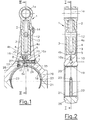
- a two-part connecting rod 1 of an internal combustion engine is shown in the upper first rod part 2, a cylindrical piston element 3 is pressed. The lower part of this piston element 3 is seated with play in a guide cylinder 4a of the lower second rod part 4 of the connecting rod 1, wherein between the piston member 3 and the second rod part 4 in at least one position of the two rod parts 2, 4, a high-pressure chamber 4b is clamped. An adjacent to the high-pressure chamber 4b pressure-side lower end face 5 of the piston member 3 is acted upon by the engine oil.
- the oil supply, lock and drain of the oil is controlled by a in a first oil passage 10 arranged control valve 6, which has an axially displaceable in a receiving bore 7 actuator piston 6a, via the oil pressure to the oil pump not shown by means of a pressure control valve, also not shown ,
- An unillustrated actuator biases a spring in the control valve of the oil pump more or less.
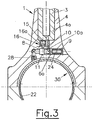
- Fig. 1 shows the connecting rod 1 in a high compression ratio associated with first position and Fig. 3 in a second position associated with a low compression ratio.
- the adjusting piston 6a is pressed in its through a bore transverse to the longitudinal axis 1a of the connecting rod 1 formed receiving bore 7 by the force of the return spring 9 at low oil pressure level against a first stop 8.
- the engine oil is sucked by the inertial force via the arranged in a second oil passage 15 check valve 16 under the end face 5 of the piston 3.
- the control piston 6a locks with its cylinder jacket 11 to the inlet and outlet opening forming a first oil passage 10.
- the sucked oil can not escape and is not compressible.
- the piston member 3 is lifted and the connecting rod 1 thus longer. In this way, a higher compression ratio can be set at normal and low oil pressure. If now the control pressure of the oil pump increases, the control piston 6a, as in Fig.
- the control pressure of the oil pump is increased and the control piston 6 is pressed by the oil pressure against the second stop 24 and the connection opening 10a to the connecting rod 30 thus opened.
- the gas pressure pushes the piston member 3 down and the lower compression ratio is reset.
- the control piston 6 is reciprocated in its receiving bore 7 from the oil pressure and the return spring 9 between the stops 8 at low oil pressure and 24 at high oil pressure.
- the pin 12 can move up and down in a slot 13 in the lower second rod portion 4 of the connecting rod 1 according to the planned extension of the connecting rod 1.
- This groove 19 in the connecting rod 1 is provided with a groove 22 in the lower shell 21 via bores 23 fluidly connected.
- the lower shell 21 is seated in the connecting rod cover 26.
- a throttle 28 is installed in the supply bore 17.
- An axial pin 14 secures the upper first part 3 against rotation.
Landscapes
- Engineering & Computer Science (AREA)
- General Engineering & Computer Science (AREA)
- Mechanical Engineering (AREA)
- Chemical & Material Sciences (AREA)
- Combustion & Propulsion (AREA)
- Output Control And Ontrol Of Special Type Engine (AREA)
- Shafts, Cranks, Connecting Bars, And Related Bearings (AREA)
Description
- Die Erfindung betrifft eine längenverstellbare Pleuelstange für eine Hubkolbenmaschine, insbesondere Brennkraftmaschine, mit zumindest einem ersten und einem zweiten Stangenteil welche beiden Stangenteile teleskopartig zu- und/ oder ineinander verschiebbar sind, wobei der zweite Stangenteil einen Führungszylinder und der erste Stangenteil ein im Führungszylinder längsverschiebbares Kolbenelement ausbildet, wobei zwischen dem ersten und dem zweiten Stangenteil ein Hochdruckraum aufgespannt ist, in den zumindest ein erster Ölkanal einmündet, in welchem zumindest ein als Steuerventil ausgebildetes Ventil angeordnet ist, dessen Stellglied durch eine Rückstellfeder in eine erste Stellung und durch Öldruck entgegen der Kraft der Rückstellfeder in eine zweite Stellung verschiebbar ist.
- Die
DE 101 51 517 A1 beschreibt eine Kolben- und Pleuelstangenanordnung mit variabler Länge zur Erzeugung eines variablen Verdichtungsverhältnisses in einem Verbrennungsmotor, mit einem ersten Teil und einem zweiten Teil, die mit einem Längenänderungsmechanismus gekoppelt sind, der zwischen den Teilen aufgenommen ist. Der Längenänderungsmechanismus weist eine kegelstumpfförmige Federscheibe und eine elastomere Masse auf, die an einer konkaven Fläche der Federscheibe anliegt. - Weitere Pleuelstangen mit jeweils einem hydraulischen teleskopartigen Mechanismus zur Verstellung der Pleuellänge sind aus den Druckschriften
FR 2 857 408 A1 EP 1 243 773 A1 ,WO 02/10568 A1 DE 198 35 146 A1 ,US 4 370 901 A ,US 4 195 601 A ,US 4 124 002 A undUS 2 134 995 A bekannt. Die DruckschriftUS 2,217,721 A offenbart eine Brennkraftmaschine mit einer längenverstellbaren Pleuelstange mit einem ersten und einem zweiten Stangenteil, welche Stangenteile teleskopartig zu - und ineinander verschiebbar sind. Zwischen den beiden Stangenteilen ist ein Hochdruckraum aufgespannt, in den ein Ölkanal einmündet. Zur Rückbefüllung und Entleerung des Hochdruckraumes mit Öl und somit zur Längenverstellung der Pleuelstange ist ein Steuerventil mit einem axial verschiebbaren Verschlussteilelement vorgesehen, welches durch eine Rückstellfeder in eine erste geschlossene Stellung und durch Öldruck entgegen der Kraft der Rückstellfeder in eine zweite offene Stellung verschiebbar ist. - Eine Brennkraftmaschine mit einer längenverstellbaren Pleuelstange ist auch aus
DE4226361 bekannt. - Eine Brennkraftmaschine mit einem längenverstellbaren Kolben ist aus
US4809650 bekannt. - Durch Ändern der Verdichtung kann Volllast mit geringerem Verdichtungsverhältnis, und Teillast und Starten mit erhöhtem Verhältnis gefahren werden. Dabei wird im Teillastbereich der Verbrauch verbessert, beim Start der Kompressionsdruck mit dem erhöhtem Verdichtungsverhältnis gesteigert und bei hoher Leistung der Spitzendruck mit verringertem Verhältnis reduziert, sowie Klopfen verhindert.
- Es ist bekannt, zur Verstellung des Verdichtungsverhältnisses einen exzentrischen Kolbenbolzen oder einen exzentrischen Hubzapfen der Kurbelwelle einzusetzen. Weiters ist es bekannt, zur Veränderung des Verdichtungsverhältnisses den ganzen Zylinderblock zu heben oder die gesamte Kurbelwellenlagerung mit einer exzentrischen Lagerung derselben im Kurbelgehäuse zu senken.
- All diese Vorschläge setzen einen hohen konstruktiven und steuerungstechnischen Aufwand voraus.
- Aufgabe der Erfindung ist es, diese Nachteile zu vermeiden und eine einfache Lösung für die Änderung des Verdichtungsverhältnisses bereitzustellen.
- Erfindungsgemäß wird dies dadurch erreicht, dass in den Hochdruckraum ein als Zuführkanal ausgebildeter zweiter Ölkanal einmündet, in welchem ein in Richtung des Hochdruckraumes öffnendes Rückschlagventil angeordnet ist, wobei das Steuerventil einen in einer Aufnahmebohrung axial verschiebbaren Stellkolben aufweist, welcher den ersten und zweiten Ölkanal auf- und zusteuert, wobei vorzugsweise in der ersten Stellung der erste Ölkanal geschlossen und in der zweiten Stellung geöffnet ist.
- Eine einfache Steuerung ergibt sich dadurch, dass der erste Ölkanal als Zu- und Abflusskanal ausgebildet ist.
- In die Aufnahmebohrung mündet ein mit dem Pleuellager strömungsverbundener Ölversorgungskanal ein, wobei besonders vorzugsweise im Ölversorgungskanal eine Drosselstelle angeordnet ist. Dadurch kann eine beim Ansaugen durch die Massenkraft des ersten Stangenteils entstehende Unterdruckwelle in Bezug auf das Öl im Pleuellager abgeschwächt werden. Dabei kann der zweite Ölzuführkanal von der Aufnahmebohrung des Steuerventils oder vom Ölversorgungskanal ausgehen.
- In einer fertigungstechnisch einfachen Ausführungsform der Erfindung ist vorgesehen, dass die Aufnahmebohrung durch eine Bohrung quer zur Längsachse der Pleuelstange gebildet ist. Eine besonders kompakte Ausführung lässt sich erzielen, wenn das Ventil im Bereich eines großen Pleuelauges der Pleuelstange angeordnet ist.
- Die Erfindung wird im Folgenden anhand der Figuren näher erläutert. Es zeigen:
- Fig. 1
- eine erfindungsgemäße Pleuelstange in einem Schnitt gemäß der Linie I - I in
Fig. 2 in einer ersten Schaltstellung; - Fig. 2
- die Pleuelstange in einem Schnitt gemäß der Linie II - II in
Fig. 1 ; und - Fig. 3
- die Pleuelstange in einem Schnitt analog zur
Fig. 1 in einer zweiten Schaltstellung. - In den
Fig. 1 bis Fig. 3 ist jeweils eine zweigeteilte Pleuelstange 1 einer Brennkraftmaschine dargestellt. Im oberen ersten Stangenteil 2 ist ein zylindrisches Kolbenelement 3 eingepresst. Der untere Teil dieses Kolbenelementes 3 sitzt mit Spielsitz in einem Führungszylinder 4a des unteren zweiten Stangenteils 4 der Pleuelstange 1, wobei zwischen dem Kolbenelement 3 und dem zweiten Stangenteil 4 in zumindest einer Lage der beiden Stangenteile 2, 4 ein Hochdruckraum 4b aufgespannt wird. Eine an den Hochdruckraum 4b grenzende druckseitige untere Stirnfläche 5 des Kolbenelementes 3 wird vom Motoröl beaufschlagt. Die Ölzufuhr, Sperre und Ablauf des Öles wird von einem in einem in einem ersten Ölkanal 10 angeordneten Steuerventil 6, welches einen in einer Aufnahmebohrung 7 axial verschiebbaren Stellkolben 6a aufweist, über den Öldruck an der nicht weiter dargestellten Ölpumpe mittels eines ebenfalls nicht dargestellten Druckregelventils gesteuert. Ein nicht dargestellter Aktuator spannt eine Feder im Regelventil der Ölpumpe mehr oder weniger vor. -
Fig. 1 zeigt die Pleuelstange 1 in einer einem hohen Verdichtungsverhältnis zugeordneten ersten Stellung undFig. 3 in einer einem niedrigen Verdichtungsverhältnis zugeordneten zweiten Stellung. - Der Stellkolben 6a wird in seiner durch eine Bohrung quer zur Längsachse 1a der Pleuelstange 1 gebildeten Aufnahmebohrung 7 durch die Kraft der Rückstellfeder 9 bei niedrigem Öldruckniveau gegen einen ersten Anschlag 8 gedrückt. Das Motoröl wird von der Massenkraft über das in einem zweiten Ölkanal 15 angeordnete Rückschlagventil 16 unter die Stirnfläche 5 des Kolbens 3 angesaugt. Der Steuerkolben 6a sperrt mit seinem Zylindermantel 11 den eine Zu- und Ablauföffnung bildenden ersten Ölkanal 10. Das angesaugte Öl kann nicht entweichen und ist nicht kompressibel. Als Folge wird das Kolbenelement 3 gehoben und die Pleuelstange 1 somit länger. Auf diese Weise kann ein höheres Verdichtungsverhältnis bei normalem und niedrigem Öldruck eingestellt werden. Wird nun der Regeldruck der Ölpumpe erhöht, wird der Steuerkolben 6a, wie in
Fig. 3 dargestellt ist, in seiner Aufnahmebohrung 7 vom Motoröl gegen den zweiten Anschlag 24 gedrückt, welcher von der Federführung 25 gebildet ist. Die Rückstellfeder 9 wird dabei zusammengedrückt. Eine Verbindungsöffnung 10a des ersten Ölkanals 10 für das Motoröl aus dem Pleuellager 30 zur Stirnfläche 5 wird durch den Steuerkolben 6 geöffnet. In dieser Stellung drückt der Gasdruck aus dem nicht weiter ersichtlichen Brennraum das Kolbenelement 3 ganz nach unten, wodurch sich ein kleineres Verdichtungsverhältnis einstellt. - Besonders vorteilhaft ist, dass auch in einem unteren Leerlaufbereich der Brennkraftmaschine, wenn der Motoröldruck kleiner als der Regeldruck ist, ein höheres Verdichtungsverhältnis eingestellt werden kann, was den Verbrauch im Niederlastbereich verbessert und einen Kaltstart erleichtert. Um das hohe Verdichtungsverhältnis über längere Zeit beizubehalten, müssen die Leckageverluste durch den Spielsitz des Führungszylinders 4a aus dem Hochdruckraum 4b unter der Stirnfläche 5 des Kolbenelementes 3 in den selben wieder nachgefüllt werden. Dies geschieht dadurch, dass die Massenkraft das Motoröl aus der inneren Bohrung 27 des Steuerkolbens 6a über das Rückschlagventil 16 (Nachfüllventil) in den Hochdruckraum 4b unter der Stirnfläche 5 ansaugt. Beim nachfolgenden Verdichtungstakt baut sich der Hochdruck wieder auf und die kleine Kugel 16a im Rückschlagventil 16 verhindert das Entweichen des Öles aus dem Hochdruckraum 4b. Dieser Vorgang wiederholt sich bei jedem Arbeitszyklus. Will man das Verdichtungsverhältnis wieder senken, wird der Regeldruck der Ölpumpe erhöht und der Steuerkolben 6 vom Öldruck gegen den zweiten Anschlag 24 gedrückt und die Verbindungsöffnung 10a zum Pleuellager 30 somit geöffnet. Der Gasdruck drückt das Kolbenelement 3 nach unten und das niedrigere Verdichtungsverhältnis ist wieder eingestellt. Der Steuerkolben 6 wird in seiner Aufnahmebohrung 7 vom Öldruck und der Rückstellfeder 9 zwischen den Anschlägen 8 bei niedrigem Öldruck und 24 bei hohem Öldruck hin- und hergeschoben.
- Ein zylindrischer Stift 12, der im Kolbenelement 3 eingepresst ist, verhindert das Herausfliegen des ersten Teils 2 der Pleuelstange 1 durch die Massenkraft. Der Stift 12 kann sich in einem Langloch 13 im unteren zweiten Stangenteil 4 der Pleuelstange 1 entsprechend der geplanten Verlängerung der Pleuelstange 1 auf- und abbewegen.
- Die Ölversorgung der Aufnahmebohrung 7 des Steuerkolbens 6 und seiner inneren Bohrung 27 erfolgt über den Ölversorgungskanal 17. Diese mündet in eine Nut 19, in der Grundbohrung 18 der Pleuellagerschale 20 des Pleuellagers 30. Diese Nut 19 in der Pleuelstange 1 ist mit einer Nut 22 in der Unterschale 21 über Bohrungen 23 strömungsverbunden. Die Unterschale 21 sitzt im Pleuelstangendeckel 26.
- Um die Unterdruckwelle , die beim Ansaugen durch die Massenkraft entsteht, gegenüber dem Öl in der Nut 19 abzuschwächen, wird eine Drossel 28 in der Versorgungsbohrung 17 eingebaut.
- Ein axialer Stift 14 sichert den oberen ersten Teil 3 gegen Verdrehen.
Claims (5)
- Längenverstellbare Pleuelstange (1) für eine Hubkolbenmaschine, insbesondere Brennkraftmaschine, mit zumindest einem ersten und einem zweiten Stangenteil (2, 4), welche beiden Stangenteile (2, 4) teleskopartig zu- und/ oder ineinander verschiebbar sind, wobei der zweite Stangenteil (4) einen Führungszylinder (4a) und der erste Stangenteil (2) ein im Führungszylinder (4a) längsverschiebbares Kolbenelement (3) ausbildet, wobei zwischen dem ersten und dem zweiten Stangenteil (2, 4) ein Hochdruckraum (4b) aufgespannt ist, in den zumindest ein erster Ölkanal (10) und ein als Zuführkanal ausgebildeter zweiter Ölkanal (15) einmünden, wobei im ersten Ölkanal (10) zumindest ein Ventil angeordnet ist, dessen Stellglied durch eine Rückstellfeder (9) in eine erste Stellung und durch Öldruck entgegen der Kraft der Rückstellfeder (9) in eine zweite Stellung verschiebbar ist, wobei im zweiten Ölkanal (15) ein in Richtung des Hochdruckraumes (4b) öffnendes Rückschlagventil (16) angeordnet ist, dadurch gekennzeichnet, dass der erste Ölkanal (10) als Zu- und Abflusskanal ausgebildet ist und das im ersten Ölkanal (10) angeordnete Ventil als Steuerventil (6) ausgebildet ist, das einen in einer Aufnahmebohrung (7) axial verschiebbaren Stellkolben (6a) aufweist, wobei in die Aufnahmebohrung (7) ein mit dem Pleuellager (30) strömungsverbundener Ölversorgungskanal (17) einmündet und der Stellkolben (6a) den ersten und zweiten Ölkanal (10, 15) auf- und zusteuert und in der ersten Stellung des Steuerventils (6) der erste Ölkanal (10) geschlossen und in der zweiten Stellung des Steuerventils (6) der erste Ölkanal (10) und eine Verbindungsöffnung (10a) des ersten Ölkanals (10) zu einem Pleuellager (30) geöffnet ist.
- Pleuelstange (1) nach Anspruch 1, dadurch gekennzeichnet, dass im Ölversorgungskanal (17) eine Drosselstelle (28) angeordnet ist.
- Pleuelstange (1) nach Anspruch 1 oder 2, dadurch gekennzeichnet, dass der zweite Ölzuführkanal (15) von der Aufnahmebohrung (7) des Steuerventils (6) oder vom Ölversorgungskanal (17) ausgeht.
- Pleuelstange (1) nach einem der Ansprüche 1 bis 3, dadurch gekennzeichnet, dass die Aufnahmebohrung (7) durch eine Bohrung quer zur Längsachse (1a) der Pleuelstange (1) gebildet ist.
- Pleuelstange (1) nach einem der Ansprüche 1 bis 4, dadurch gekennzeichnet, dass das Steuerventil (6) im Bereich eines Pleuellagers (30) der Pleuelstange (1) angeordnet ist.
Applications Claiming Priority (2)
| Application Number | Priority Date | Filing Date | Title |
|---|---|---|---|
| ATA50020/2011A AT511803B1 (de) | 2011-12-23 | 2011-12-23 | Pleuelstange für eine hubkolbenmaschine |
| PCT/EP2012/075344 WO2013092364A1 (de) | 2011-12-23 | 2012-12-13 | Pleuelstange für eine hubkolbenmaschine |
Publications (2)
| Publication Number | Publication Date |
|---|---|
| EP2795082A1 EP2795082A1 (de) | 2014-10-29 |
| EP2795082B1 true EP2795082B1 (de) | 2019-05-15 |
Family
ID=47356054
Family Applications (1)
| Application Number | Title | Priority Date | Filing Date |
|---|---|---|---|
| EP12799574.4A Not-in-force EP2795082B1 (de) | 2011-12-23 | 2012-12-13 | Pleuelstange für eine hubkolbenmaschine |
Country Status (7)
| Country | Link |
|---|---|
| US (1) | US9528546B2 (de) |
| EP (1) | EP2795082B1 (de) |
| JP (1) | JP6236015B2 (de) |
| KR (1) | KR101989041B1 (de) |
| CN (1) | CN104126064B (de) |
| AT (2) | AT511803B1 (de) |
| WO (1) | WO2013092364A1 (de) |
Families Citing this family (81)
| Publication number | Priority date | Publication date | Assignee | Title |
|---|---|---|---|---|
| DE102013105389B4 (de) * | 2013-05-27 | 2021-12-23 | Dr. Ing. H.C. F. Porsche Aktiengesellschaft | Umschaltventil und Verbrennungsmotor mit einem solchen Umschaltventil |
| AT514071B1 (de) * | 2013-10-18 | 2014-10-15 | Avl List Gmbh | Längenverstellbare Pleuelstange |
| DE102013021065A1 (de) * | 2013-12-18 | 2015-06-18 | Fev Gmbh | Kolbenmaschine mit Stützkolben |
| WO2015108178A1 (ja) * | 2014-01-20 | 2015-07-23 | 株式会社Ihi | クロスヘッド型エンジン |
| JP6137340B2 (ja) * | 2014-01-20 | 2017-05-31 | 株式会社Ihi | クロスヘッド型エンジン |
| KR101799956B1 (ko) | 2014-01-20 | 2017-11-21 | 가부시키가이샤 아이에이치아이 | 엔진 |
| CN104061228A (zh) * | 2014-06-12 | 2014-09-24 | 王立华 | 可变压缩比发动机连杆机构 |
| DE102015001066B3 (de) * | 2015-01-29 | 2015-10-22 | Armin Brunner | Hydraulisch längenverstellbare Pleuelstange |
| JP6451485B2 (ja) * | 2015-05-11 | 2019-01-16 | 株式会社Ihi | クロスヘッド型エンジン |
| JP6451486B2 (ja) * | 2015-05-11 | 2019-01-16 | 株式会社Ihi | 油圧発生装置およびクロスヘッド型エンジン |
| WO2016203047A1 (de) | 2015-06-18 | 2016-12-22 | Avl List Gmbh | Längenverstellbare pleuelstange |
| AT15426U1 (de) | 2015-08-10 | 2017-08-15 | Avl List Gmbh | Hubkolbenmaschine, insbesondere Brennkraftmaschine |
| AT517716B1 (de) * | 2015-10-28 | 2017-04-15 | Avl List Gmbh | Mehrzylinder-brennkraftmaschine |
| AT517619B1 (de) * | 2015-11-05 | 2017-03-15 | Avl List Gmbh | Längenverstellbare pleuelstange |
| FR3043740B1 (fr) * | 2015-11-17 | 2018-01-05 | MCE 5 Development | Bielle pour moteur a rapport volumetrique variable |
| FR3043720B1 (fr) | 2015-11-17 | 2019-11-08 | MCE 5 Development | Moteur a rapport volumetrique variable |
| US10954849B2 (en) | 2015-12-14 | 2021-03-23 | Avl List Gmbh | Length-adjustable connecting rod with electromagnetically-actuatable switching valve |
| WO2017102108A1 (de) | 2015-12-14 | 2017-06-22 | Avl List Gmbh | Längenverstellbare pleuelstange mit elektromagnetisch betätigbarem schaltventil |
| JP6365570B2 (ja) * | 2016-02-29 | 2018-08-01 | トヨタ自動車株式会社 | 可変長コンロッド及び可変圧縮比内燃機関 |
| AT518408B1 (de) * | 2016-04-05 | 2017-10-15 | Avl List Gmbh | Ventilbetätigungseinrichtung für zumindest ein gaswechselventil |
| AT15576U1 (de) * | 2016-04-29 | 2018-03-15 | Avl List Gmbh | Längenverstellbare Pleuelstange |
| AT518694B1 (de) | 2016-05-31 | 2019-08-15 | Avl List Gmbh | Hubkolbenmaschine sowie Verfahren und Vorrichtung zur Diagnose und/oder Steuerung einer Hubkolbenmaschine |
| AT519011B1 (de) | 2016-05-31 | 2018-03-15 | Avl List Gmbh | Hubkolbenmaschine |
| AT518268B1 (de) | 2016-05-31 | 2017-09-15 | Avl List Gmbh | Verfahren und System zur Diagnose und/oder Steuerung einer Hubkolbenmaschine mit einem variablen Verdichtungsverhältnis |
| CN106089977B (zh) * | 2016-06-08 | 2018-11-20 | 北汽福田汽车股份有限公司 | 发动机连杆机构、发动机可变压缩比系统、发动机和车辆 |
| DE102016008306A1 (de) | 2016-07-06 | 2018-01-11 | Avl List Gmbh | Pleuel mit verstellbarer Pleuellänge |
| WO2018007534A1 (de) * | 2016-07-06 | 2018-01-11 | Avl List Gmbh | Pleuel mit verstellbarer pleuellänge mit mechanischer betätigung |
| USD801151S1 (en) * | 2016-07-08 | 2017-10-31 | Race Winning Brands, Inc. | I-beam connecting rod |
| DE102017106987A1 (de) * | 2016-07-08 | 2018-01-11 | ECO Holding 1 GmbH | Rückschlagventil für ein Pleuel für eine Brennkraftmaschine mit variabler Verdichtung |
| DE102016113640A1 (de) | 2016-07-25 | 2018-01-25 | Hilite Germany Gmbh | Pleuel für eine Brennkraftmaschine mit variabler Verdichtung |
| DE202017007696U1 (de) | 2016-08-16 | 2024-07-15 | ECO Holding 1 GmbH | Pleuel für eine Brennkraftmaschine mit variabler Verdichtung |
| US20170009647A1 (en) * | 2016-09-22 | 2017-01-12 | Caterpillar Inc. | Connecting rod |
| WO2018060458A1 (de) * | 2016-09-30 | 2018-04-05 | Avl List Gmbh | Längenverstellbares pleuel mit anschlagflächen |
| AT519184B1 (de) * | 2016-09-30 | 2018-07-15 | Avl List Gmbh | Längenverstellbares Pleuel mit Anschlagflächen |
| AT519140B1 (de) | 2016-09-30 | 2018-11-15 | Avl List Gmbh | Längenverstellbares Pleuel mit mechanischer Verstellung |
| DE102016120963A1 (de) | 2016-11-03 | 2018-05-03 | Avl List Gmbh | Längenverstellbare Pleuelstange mit einer Zylinder-Kolben-Einheit mit Spaltdichtung, Ölreservoir, Ölfilter und Ölabstreifer |
| DE102016120973A1 (de) | 2016-11-03 | 2018-05-03 | Avl List Gmbh | Längenverstellbare Pleuelstange mit einer Zylinder-Kolben-Einheit mit Ölführungsstange |
| DE102016120943A1 (de) | 2016-11-03 | 2018-05-03 | Avl List Gmbh | Pleuelstange mit Verstellmechanismus zwischen Pleuelfuß und Kolbenstange |
| DE102016120964A1 (de) | 2016-11-03 | 2018-05-03 | Avl List Gmbh | Längenverstellbare Pleuelstange mit einer Zylinder-Kolben-Einheit mit Zylinderhülse |
| DE102016120975A1 (de) | 2016-11-03 | 2018-05-03 | Avl List Gmbh | Längenverstellbare Pleuelstange mit einer Zylinder-Kolben-Einheit mit Ölfilter |
| DE102016120942A1 (de) | 2016-11-03 | 2018-05-03 | Avl List Gmbh | Pleuelstange mit Stufenkolben |
| DE102016120970A1 (de) | 2016-11-03 | 2018-05-03 | Avl List Gmbh | Längenverstellbare Pleuelstange mit einer Zylinder-Kolben-Einheit mit Spaltdichtung und dehnbarem Kolbenkragen |
| DE102016120994A1 (de) | 2016-11-03 | 2018-05-03 | Avl List Gmbh | Längenverstellbare Pleuelstange mit einer Zylinder-Kolben-Einheit mit Ölabstreifer |
| DE102016120948A1 (de) | 2016-11-03 | 2018-05-03 | Avl List Gmbh | Pleuelstange mit Verstellmechanismus zwischen Pleuelfuß und Pleuelkopf |
| DE102016120946A1 (de) | 2016-11-03 | 2018-05-03 | Avl List Gmbh | Längenverstellbare Pleuelstange mit einer Zylinder-Kolben-Einheit mit konischer Spaltdichtung |
| DE102016120967A1 (de) | 2016-11-03 | 2018-05-03 | Avl List Gmbh | Längenverstellbare Pleuelstange mit einer Zylinder-Kolben-Einheit mit mehreren Kolbendichtungen |
| DE102016120950A1 (de) * | 2016-11-03 | 2018-05-03 | Avl List Gmbh | Pleuelstange mit gekapselter Baugruppe zur Längenverstellung |
| AT519360B1 (de) | 2017-02-24 | 2018-06-15 | Avl List Gmbh | Verfahren zum Betrieb einer Hubkolbenmaschine mit wenigstens einer hydraulisch längenverstellbaren Pleuelstange |
| DE102017107718A1 (de) | 2017-04-10 | 2018-10-11 | Avl List Gmbh | Ventilmechanismus für eine längenverstellbare Pleuelstange |
| DE102017107711A1 (de) * | 2017-04-10 | 2018-10-11 | Avl List Gmbh | Längenverstellbare Pleuelstange mit Toleranzausgleich |
| DE102017107706A1 (de) | 2017-04-10 | 2018-10-11 | Avl List Gmbh | Längenverstellbare Pleuelstange mit einer Zylinder-Kolben-Einheit mit Verdrehsicherung |
| DE102017108888A1 (de) | 2017-04-26 | 2018-10-31 | Schaeffler Technologies AG & Co. KG | Pleuelstange einer Hubkolbenmaschine |
| DE102017110446A1 (de) | 2017-05-15 | 2018-11-15 | ECO Holding 1 GmbH | Pleuel für eine Brennkraftmaschine mit variabler Verdichtung |
| AT520079B1 (de) * | 2017-05-31 | 2019-01-15 | Avl List Gmbh | Hubkolbenmaschine sowie Verfahren und Vorrichtung zur Diagnose und/oder Steuerung einer Hubkolbenmaschine |
| JP6904130B2 (ja) * | 2017-07-21 | 2021-07-14 | 株式会社Ihi | 可変圧縮装置及びエンジンシステム |
| DE102018104292A1 (de) | 2018-02-26 | 2019-08-29 | Avl List Gmbh | Sensoreinrichtung für eine längenverstellbare Pleuelstange |
| FR3081525B1 (fr) * | 2018-05-25 | 2020-05-08 | MCE 5 Development | Vilebrequin pour un moteur a rapport volumetrique variable pilote |
| DE102019103998A1 (de) | 2018-06-27 | 2019-08-29 | FEV Europe GmbH | Pleuel einer Verbrennungskraftmaschine zur Änderung des Verdichtungsverhältnisses |
| AT521269B1 (de) * | 2018-10-08 | 2019-12-15 | Avl List Gmbh | Hydraulisches Steuerventil für eine längenverstellbare Pleuelstange mit zwei Steuerdruckräumen |
| AT521268B1 (de) * | 2018-10-08 | 2019-12-15 | Avl List Gmbh | Längenverstellbare Pleuelstange mit hydraulischer Steuereinrichtung |
| AT521676B1 (de) * | 2018-10-08 | 2020-04-15 | Avl List Gmbh | Längenverstellbare Pleuelstange mit mechanisch betätigbarem Ventil |
| AT521675B1 (de) * | 2018-10-08 | 2020-04-15 | Avl List Gmbh | Hydraulisches Steuerventil für eine längenverstellbare Pleuelstange mit zwei stirnseitigen Steuerkolben |
| AT521256B1 (de) * | 2018-10-08 | 2019-12-15 | Avl List Gmbh | Hydraulisches Steuerventil für eine längenverstellbare Pleuelstange mit geteilter Drainage |
| AT521678B1 (de) * | 2018-10-08 | 2020-04-15 | Avl List Gmbh | Längenverstellbare Pleuelstange mit masseoptimiertem Steuerschieber |
| AT521146B1 (de) | 2018-10-08 | 2019-11-15 | Avl List Gmbh | Hydraulisches Steuerventil für eine längenverstellbare Pleuelstange mit einem Hohlschieber |
| AT521159B1 (de) | 2018-10-08 | 2019-11-15 | Avl List Gmbh | Hydraulisches Steuerventil für eine längenverstellbare Pleuelstange mit einem stirnseitigen Steuerkolben |
| US11350398B2 (en) | 2018-10-26 | 2022-05-31 | Lg Electronics Inc. | Method and apparatus for transmitting and receiving downlink data channel |
| AT521520B1 (de) * | 2018-11-07 | 2020-02-15 | Avl List Gmbh | System und Verfahren zum Einstellen einer wirksamen Länge einer Pleuelstange sowie Brennkraftmaschine |
| AT521515B1 (de) * | 2018-11-07 | 2020-02-15 | Avl List Gmbh | System und Verfahren zum Einstellen einer wirksamen Länge einer Pleuelstange sowie Brennkraftmaschine |
| AT521521B1 (de) | 2018-11-07 | 2020-02-15 | Avl List Gmbh | System und Verfahren zum Einstellen einer wirksamen Länge einer Pleuelstange sowie Brennkraftmaschine |
| AT521686B1 (de) * | 2018-12-03 | 2020-04-15 | Avl List Gmbh | Verfahren zum Warmauslagern einer Schweißnaht an einer längenverstellbaren Pleuelstange |
| AT521887B1 (de) | 2018-12-04 | 2021-06-15 | Avl List Gmbh | System und Verfahren zum Einstellen einer wirksamen Länge einer Pleuelstange mittels Schmiermittelversorgung |
| AT522159B1 (de) * | 2019-03-08 | 2020-09-15 | Avl List Gmbh | Schraubverbindung für längenverstellbare Pleuelstange mit Schmelzeinlage |
| AT16800U1 (de) * | 2019-03-08 | 2020-09-15 | Avl List Gmbh | Schraubverbindung für längenverstellbare Pleuelstange mit unterschiedlicher Gewindesteigung |
| CN111828170B (zh) * | 2019-04-16 | 2021-11-23 | 广州汽车集团股份有限公司 | 用于可变压缩比发动机的连杆 |
| WO2020223750A1 (de) * | 2019-05-03 | 2020-11-12 | Iwis Motorsysteme Gmbh & Co. Kg | Steuerschieber mit zwei steuerschieberteilen für eine längsverstellbare pleuelstange |
| AT522322B1 (de) | 2019-05-15 | 2020-10-15 | Avl List Gmbh | Pleuelstange mit formschlüssiger Verbindung |
| FR3102814B1 (fr) * | 2019-11-04 | 2021-11-26 | MCE 5 Development | Bielle à longueur variable pour moteur à rapport volumétrique piloté |
| CN113494513B (zh) * | 2020-04-07 | 2022-08-19 | 广州汽车集团股份有限公司 | 长度可变的连杆装置 |
| CN113530693B (zh) * | 2020-04-15 | 2022-06-21 | 广州汽车集团股份有限公司 | 一种控制阀、控制油路及可变压缩比发动机 |
| AT524987B1 (de) | 2021-04-30 | 2023-06-15 | Avl List Gmbh | Verfahren zum Einstellen einer wirksamen Länge einer Pleuelstange |
Citations (1)
| Publication number | Priority date | Publication date | Assignee | Title |
|---|---|---|---|---|
| DE4226361A1 (de) * | 1992-08-10 | 1994-04-07 | Alex Zimmer | Brennkraftmaschine |
Family Cites Families (26)
| Publication number | Priority date | Publication date | Assignee | Title |
|---|---|---|---|---|
| US2134995A (en) | 1935-11-13 | 1938-11-01 | George A Anderson | Adjustable stroke and shock absorbing connecting rod |
| US2217721A (en) * | 1938-09-14 | 1940-10-15 | Mary Adeline Reynolds | Internal combustion engine |
| US2667079A (en) * | 1951-10-24 | 1954-01-26 | Siemens Ag | Reciprocating tappet device of variable tappet length |
| US4124002A (en) * | 1976-07-23 | 1978-11-07 | Crise George W | Pressure-responsive variable length connecting rod |
| US4195601A (en) | 1978-10-30 | 1980-04-01 | Crise George W | Controlled compression internal combustion engine having fluid pressure extensible connecting rod |
| US4370901A (en) | 1981-01-05 | 1983-02-01 | John Sawyer | Connecting rod with variable length |
| JPS61122417U (de) * | 1985-01-17 | 1986-08-01 | ||
| US4809650A (en) | 1986-10-09 | 1989-03-07 | Nissan Motor Co., Ltd. | Variable compression control arrangement for internal combustion engine |
| JPH076418B2 (ja) * | 1986-10-09 | 1995-01-30 | 株式会社ユニシアジェックス | 内燃機関の圧縮比可変装置 |
| JPH0826791B2 (ja) * | 1987-02-09 | 1996-03-21 | 株式会社ユニシアジェックス | 内燃機関の圧縮比可変装置 |
| US4864977A (en) * | 1987-07-03 | 1989-09-12 | Honda Giken Kogyo Kabushiki Kaisha | Compression ratio-changing device for internal combustion engines |
| JP3749313B2 (ja) * | 1996-08-06 | 2006-02-22 | トヨタ自動車株式会社 | 負圧制御弁 |
| DE19835146A1 (de) | 1998-08-04 | 1999-06-10 | Daimler Chrysler Ag | Pleuelstange |
| AU2001277146A1 (en) * | 2000-08-02 | 2002-02-13 | Jerry I. Yadegar | Hydraulically adjustable connecting rod for internal combustion engine efficiency |
| US6568357B1 (en) | 2000-10-18 | 2003-05-27 | Ford Global Technologies, Inc. | Variable compression ratio pistons and connecting rods |
| DE50104202D1 (de) | 2001-03-19 | 2004-11-25 | Ford Global Tech Inc | Laengenverstellbare Pleuelstange |
| FR2857408B1 (fr) | 2003-07-09 | 2007-09-28 | Inst Francais Du Petrole | Moteur a combustion interne a balayage des gaz brules residuels presents dans une chambre de combustion et procede permettant un tel balayage |
| CN2828338Y (zh) * | 2005-06-01 | 2006-10-18 | 胡在权 | 一种内燃机可伸缩连杆 |
| JP4252996B2 (ja) * | 2005-12-28 | 2009-04-08 | 本田技研工業株式会社 | 内燃機関の圧縮比可変装置 |
| JP4464916B2 (ja) * | 2005-12-28 | 2010-05-19 | 本田技研工業株式会社 | ピストンにおける油圧アクチュエータの制御装置 |
| CN101109321A (zh) * | 2007-08-08 | 2008-01-23 | 陈晨 | 自适应可变压缩比发动机 |
| US7546820B2 (en) * | 2007-10-31 | 2009-06-16 | Ford Global Technologies, Llc | Variable compression ratio engine with lost motion coupling |
| US7827943B2 (en) * | 2008-02-19 | 2010-11-09 | Tonand Brakes Inc | Variable compression ratio system |
| US8151691B2 (en) * | 2008-12-04 | 2012-04-10 | Southwest Research Institute | Variable compression ratio piston with rate-sensitive response |
| WO2010108582A1 (de) * | 2009-03-26 | 2010-09-30 | Ixetic Bad Homburg Gmbh | Vorrichtung zur veränderung des verdichtungsverhältnisses in einem verbrennungsmotor |
| US8746188B2 (en) | 2010-03-17 | 2014-06-10 | Larry C. Wilkins | Internal combustion engine with hydraulically-affected stroke |
-
2011
- 2011-12-23 AT ATA50020/2011A patent/AT511803B1/de not_active IP Right Cessation
-
2012
- 2012-07-03 AT ATA50262/2012A patent/AT512334A1/de not_active Application Discontinuation
- 2012-12-13 CN CN201280070177.8A patent/CN104126064B/zh not_active Expired - Fee Related
- 2012-12-13 KR KR1020147019177A patent/KR101989041B1/ko not_active Expired - Fee Related
- 2012-12-13 WO PCT/EP2012/075344 patent/WO2013092364A1/de not_active Ceased
- 2012-12-13 JP JP2014547858A patent/JP6236015B2/ja not_active Expired - Fee Related
- 2012-12-13 US US14/367,993 patent/US9528546B2/en not_active Expired - Fee Related
- 2012-12-13 EP EP12799574.4A patent/EP2795082B1/de not_active Not-in-force
Patent Citations (1)
| Publication number | Priority date | Publication date | Assignee | Title |
|---|---|---|---|---|
| DE4226361A1 (de) * | 1992-08-10 | 1994-04-07 | Alex Zimmer | Brennkraftmaschine |
Also Published As
| Publication number | Publication date |
|---|---|
| JP6236015B2 (ja) | 2017-11-22 |
| KR20140108678A (ko) | 2014-09-12 |
| US20140366834A1 (en) | 2014-12-18 |
| JP2015503058A (ja) | 2015-01-29 |
| CN104126064B (zh) | 2017-10-24 |
| AT512334A1 (de) | 2013-07-15 |
| AT511803B1 (de) | 2013-03-15 |
| KR101989041B1 (ko) | 2019-06-13 |
| CN104126064A (zh) | 2014-10-29 |
| WO2013092364A1 (de) | 2013-06-27 |
| AT511803A4 (de) | 2013-03-15 |
| US9528546B2 (en) | 2016-12-27 |
| EP2795082A1 (de) | 2014-10-29 |
Similar Documents
| Publication | Publication Date | Title |
|---|---|---|
| EP2795082B1 (de) | Pleuelstange für eine hubkolbenmaschine | |
| EP2870370B1 (de) | Längenverstellbare pleuelstange | |
| AT514071B1 (de) | Längenverstellbare Pleuelstange | |
| DE102014106715A1 (de) | Umschaltventil und Verbrennungsmotor | |
| AT517511A1 (de) | Hubkolbenmaschine, insbesondere brennkraftmaschine | |
| AT518848A1 (de) | Pleuel mit verstellbarer Pleuellänge mit mechanischer Betätigung | |
| WO2010055100A1 (de) | Pumpeneinheit für eine hochdruckpumpe | |
| AT519156B1 (de) | Längenverstellbares Pleuel für eine Hubkolbenmaschine, Hubkolbenmaschine und Fahrzeug | |
| EP3058223B1 (de) | Ein hochdruckmedium führendes bauelement | |
| WO2018083256A1 (de) | Längenverstellbare pleuelstange mit einer zylinder-kolben-einheit mit mehreren kolbendichtungen | |
| AT521256A4 (de) | Hydraulisches Steuerventil für eine längenverstellbare Pleuelstange mit geteilter Drainage | |
| DE102016203559A1 (de) | Hydraulisch betätigtes Schaltventil | |
| AT519294A2 (de) | Längenverstellbare Pleuelstange mit einer Zylinder-Kolben-Einheit mit Zylinderhülse | |
| AT517716B1 (de) | Mehrzylinder-brennkraftmaschine | |
| DE102016211999A1 (de) | Hydraulisch betätigtes Wegeventil zur Einstellung eines variablen Verdichtungsverhältnisses einer Hubkolbenbrennkraftmaschine | |
| AT522793B1 (de) | Kompakter hydraulischer Ventilmechanismus für eine längenverstellbare Pleuelstange | |
| AT524567B1 (de) | Längenverstellbare Pleuelstange mit kompaktem Ablassventil | |
| AT16800U1 (de) | Schraubverbindung für längenverstellbare Pleuelstange mit unterschiedlicher Gewindesteigung | |
| DE102017111395A1 (de) | Vorrichtung zur Veränderung des Verdichtungsverhältnisses einer Hubkolbenbrennkraftmaschine | |
| AT521146B1 (de) | Hydraulisches Steuerventil für eine längenverstellbare Pleuelstange mit einem Hohlschieber | |
| AT519799A2 (de) | Längenverstellbare Pleuelstange mit einer Zylinder-Kolben-Einheit mit Verdrehsicherung | |
| DE202017007697U1 (de) | Pleuel mit einem Kugelgelenk | |
| AT522194A1 (de) | Steuerschieber mit separatem Steuerkolben für eine längenverstellbare Pleuelstange | |
| DE102017109172A1 (de) | Pleuel mit einem Kugelgelenk sowie Verfahren zur Herstellung einer Kugelgelenkverbindung | |
| WO2017198615A1 (de) | Pleuel für eine brennkraftmaschine mit variabler verdichtung |
Legal Events
| Date | Code | Title | Description |
|---|---|---|---|
| PUAI | Public reference made under article 153(3) epc to a published international application that has entered the european phase |
Free format text: ORIGINAL CODE: 0009012 |
|
| 17P | Request for examination filed |
Effective date: 20140609 |
|
| AK | Designated contracting states |
Kind code of ref document: A1 Designated state(s): AL AT BE BG CH CY CZ DE DK EE ES FI FR GB GR HR HU IE IS IT LI LT LU LV MC MK MT NL NO PL PT RO RS SE SI SK SM TR |
|
| DAX | Request for extension of the european patent (deleted) | ||
| 17Q | First examination report despatched |
Effective date: 20160620 |
|
| STAA | Information on the status of an ep patent application or granted ep patent |
Free format text: STATUS: EXAMINATION IS IN PROGRESS |
|
| GRAP | Despatch of communication of intention to grant a patent |
Free format text: ORIGINAL CODE: EPIDOSNIGR1 |
|
| STAA | Information on the status of an ep patent application or granted ep patent |
Free format text: STATUS: GRANT OF PATENT IS INTENDED |
|
| INTG | Intention to grant announced |
Effective date: 20181219 |
|
| GRAS | Grant fee paid |
Free format text: ORIGINAL CODE: EPIDOSNIGR3 |
|
| GRAA | (expected) grant |
Free format text: ORIGINAL CODE: 0009210 |
|
| STAA | Information on the status of an ep patent application or granted ep patent |
Free format text: STATUS: THE PATENT HAS BEEN GRANTED |
|
| AK | Designated contracting states |
Kind code of ref document: B1 Designated state(s): AL AT BE BG CH CY CZ DE DK EE ES FI FR GB GR HR HU IE IS IT LI LT LU LV MC MK MT NL NO PL PT RO RS SE SI SK SM TR |
|
| REG | Reference to a national code |
Ref country code: CH Ref legal event code: EP Ref country code: GB Ref legal event code: FG4D Free format text: NOT ENGLISH |
|
| REG | Reference to a national code |
Ref country code: DE Ref legal event code: R096 Ref document number: 502012014791 Country of ref document: DE |
|
| REG | Reference to a national code |
Ref country code: IE Ref legal event code: FG4D Free format text: LANGUAGE OF EP DOCUMENT: GERMAN |
|
| REG | Reference to a national code |
Ref country code: SE Ref legal event code: TRGR |
|
| REG | Reference to a national code |
Ref country code: NL Ref legal event code: MP Effective date: 20190515 |
|
| REG | Reference to a national code |
Ref country code: LT Ref legal event code: MG4D |
|
| PG25 | Lapsed in a contracting state [announced via postgrant information from national office to epo] |
Ref country code: NL Free format text: LAPSE BECAUSE OF FAILURE TO SUBMIT A TRANSLATION OF THE DESCRIPTION OR TO PAY THE FEE WITHIN THE PRESCRIBED TIME-LIMIT Effective date: 20190515 Ref country code: HR Free format text: LAPSE BECAUSE OF FAILURE TO SUBMIT A TRANSLATION OF THE DESCRIPTION OR TO PAY THE FEE WITHIN THE PRESCRIBED TIME-LIMIT Effective date: 20190515 Ref country code: LT Free format text: LAPSE BECAUSE OF FAILURE TO SUBMIT A TRANSLATION OF THE DESCRIPTION OR TO PAY THE FEE WITHIN THE PRESCRIBED TIME-LIMIT Effective date: 20190515 Ref country code: PT Free format text: LAPSE BECAUSE OF FAILURE TO SUBMIT A TRANSLATION OF THE DESCRIPTION OR TO PAY THE FEE WITHIN THE PRESCRIBED TIME-LIMIT Effective date: 20190915 Ref country code: NO Free format text: LAPSE BECAUSE OF FAILURE TO SUBMIT A TRANSLATION OF THE DESCRIPTION OR TO PAY THE FEE WITHIN THE PRESCRIBED TIME-LIMIT Effective date: 20190815 Ref country code: ES Free format text: LAPSE BECAUSE OF FAILURE TO SUBMIT A TRANSLATION OF THE DESCRIPTION OR TO PAY THE FEE WITHIN THE PRESCRIBED TIME-LIMIT Effective date: 20190515 Ref country code: AL Free format text: LAPSE BECAUSE OF FAILURE TO SUBMIT A TRANSLATION OF THE DESCRIPTION OR TO PAY THE FEE WITHIN THE PRESCRIBED TIME-LIMIT Effective date: 20190515 Ref country code: FI Free format text: LAPSE BECAUSE OF FAILURE TO SUBMIT A TRANSLATION OF THE DESCRIPTION OR TO PAY THE FEE WITHIN THE PRESCRIBED TIME-LIMIT Effective date: 20190515 |
|
| PG25 | Lapsed in a contracting state [announced via postgrant information from national office to epo] |
Ref country code: GR Free format text: LAPSE BECAUSE OF FAILURE TO SUBMIT A TRANSLATION OF THE DESCRIPTION OR TO PAY THE FEE WITHIN THE PRESCRIBED TIME-LIMIT Effective date: 20190816 Ref country code: BG Free format text: LAPSE BECAUSE OF FAILURE TO SUBMIT A TRANSLATION OF THE DESCRIPTION OR TO PAY THE FEE WITHIN THE PRESCRIBED TIME-LIMIT Effective date: 20190815 Ref country code: RS Free format text: LAPSE BECAUSE OF FAILURE TO SUBMIT A TRANSLATION OF THE DESCRIPTION OR TO PAY THE FEE WITHIN THE PRESCRIBED TIME-LIMIT Effective date: 20190515 Ref country code: LV Free format text: LAPSE BECAUSE OF FAILURE TO SUBMIT A TRANSLATION OF THE DESCRIPTION OR TO PAY THE FEE WITHIN THE PRESCRIBED TIME-LIMIT Effective date: 20190515 |
|
| PG25 | Lapsed in a contracting state [announced via postgrant information from national office to epo] |
Ref country code: EE Free format text: LAPSE BECAUSE OF FAILURE TO SUBMIT A TRANSLATION OF THE DESCRIPTION OR TO PAY THE FEE WITHIN THE PRESCRIBED TIME-LIMIT Effective date: 20190515 Ref country code: DK Free format text: LAPSE BECAUSE OF FAILURE TO SUBMIT A TRANSLATION OF THE DESCRIPTION OR TO PAY THE FEE WITHIN THE PRESCRIBED TIME-LIMIT Effective date: 20190515 Ref country code: SK Free format text: LAPSE BECAUSE OF FAILURE TO SUBMIT A TRANSLATION OF THE DESCRIPTION OR TO PAY THE FEE WITHIN THE PRESCRIBED TIME-LIMIT Effective date: 20190515 Ref country code: CZ Free format text: LAPSE BECAUSE OF FAILURE TO SUBMIT A TRANSLATION OF THE DESCRIPTION OR TO PAY THE FEE WITHIN THE PRESCRIBED TIME-LIMIT Effective date: 20190515 Ref country code: RO Free format text: LAPSE BECAUSE OF FAILURE TO SUBMIT A TRANSLATION OF THE DESCRIPTION OR TO PAY THE FEE WITHIN THE PRESCRIBED TIME-LIMIT Effective date: 20190515 |
|
| REG | Reference to a national code |
Ref country code: DE Ref legal event code: R097 Ref document number: 502012014791 Country of ref document: DE |
|
| PG25 | Lapsed in a contracting state [announced via postgrant information from national office to epo] |
Ref country code: SM Free format text: LAPSE BECAUSE OF FAILURE TO SUBMIT A TRANSLATION OF THE DESCRIPTION OR TO PAY THE FEE WITHIN THE PRESCRIBED TIME-LIMIT Effective date: 20190515 |
|
| PLBE | No opposition filed within time limit |
Free format text: ORIGINAL CODE: 0009261 |
|
| STAA | Information on the status of an ep patent application or granted ep patent |
Free format text: STATUS: NO OPPOSITION FILED WITHIN TIME LIMIT |
|
| PG25 | Lapsed in a contracting state [announced via postgrant information from national office to epo] |
Ref country code: TR Free format text: LAPSE BECAUSE OF FAILURE TO SUBMIT A TRANSLATION OF THE DESCRIPTION OR TO PAY THE FEE WITHIN THE PRESCRIBED TIME-LIMIT Effective date: 20190515 |
|
| 26N | No opposition filed |
Effective date: 20200218 |
|
| PG25 | Lapsed in a contracting state [announced via postgrant information from national office to epo] |
Ref country code: PL Free format text: LAPSE BECAUSE OF FAILURE TO SUBMIT A TRANSLATION OF THE DESCRIPTION OR TO PAY THE FEE WITHIN THE PRESCRIBED TIME-LIMIT Effective date: 20190515 |
|
| PG25 | Lapsed in a contracting state [announced via postgrant information from national office to epo] |
Ref country code: SI Free format text: LAPSE BECAUSE OF FAILURE TO SUBMIT A TRANSLATION OF THE DESCRIPTION OR TO PAY THE FEE WITHIN THE PRESCRIBED TIME-LIMIT Effective date: 20190515 |
|
| REG | Reference to a national code |
Ref country code: CH Ref legal event code: PL |
|
| REG | Reference to a national code |
Ref country code: BE Ref legal event code: MM Effective date: 20191231 |
|
| PG25 | Lapsed in a contracting state [announced via postgrant information from national office to epo] |
Ref country code: MC Free format text: LAPSE BECAUSE OF FAILURE TO SUBMIT A TRANSLATION OF THE DESCRIPTION OR TO PAY THE FEE WITHIN THE PRESCRIBED TIME-LIMIT Effective date: 20190515 |
|
| PG25 | Lapsed in a contracting state [announced via postgrant information from national office to epo] |
Ref country code: LU Free format text: LAPSE BECAUSE OF NON-PAYMENT OF DUE FEES Effective date: 20191213 Ref country code: IE Free format text: LAPSE BECAUSE OF NON-PAYMENT OF DUE FEES Effective date: 20191213 |
|
| PG25 | Lapsed in a contracting state [announced via postgrant information from national office to epo] |
Ref country code: LI Free format text: LAPSE BECAUSE OF NON-PAYMENT OF DUE FEES Effective date: 20191231 Ref country code: CH Free format text: LAPSE BECAUSE OF NON-PAYMENT OF DUE FEES Effective date: 20191231 Ref country code: BE Free format text: LAPSE BECAUSE OF NON-PAYMENT OF DUE FEES Effective date: 20191231 |
|
| REG | Reference to a national code |
Ref country code: AT Ref legal event code: MM01 Ref document number: 1133698 Country of ref document: AT Kind code of ref document: T Effective date: 20191213 |
|
| PG25 | Lapsed in a contracting state [announced via postgrant information from national office to epo] |
Ref country code: CY Free format text: LAPSE BECAUSE OF FAILURE TO SUBMIT A TRANSLATION OF THE DESCRIPTION OR TO PAY THE FEE WITHIN THE PRESCRIBED TIME-LIMIT Effective date: 20190515 Ref country code: AT Free format text: LAPSE BECAUSE OF NON-PAYMENT OF DUE FEES Effective date: 20191213 |
|
| PG25 | Lapsed in a contracting state [announced via postgrant information from national office to epo] |
Ref country code: IS Free format text: LAPSE BECAUSE OF FAILURE TO SUBMIT A TRANSLATION OF THE DESCRIPTION OR TO PAY THE FEE WITHIN THE PRESCRIBED TIME-LIMIT Effective date: 20190915 |
|
| PG25 | Lapsed in a contracting state [announced via postgrant information from national office to epo] |
Ref country code: MT Free format text: LAPSE BECAUSE OF FAILURE TO SUBMIT A TRANSLATION OF THE DESCRIPTION OR TO PAY THE FEE WITHIN THE PRESCRIBED TIME-LIMIT Effective date: 20190515 Ref country code: HU Free format text: LAPSE BECAUSE OF FAILURE TO SUBMIT A TRANSLATION OF THE DESCRIPTION OR TO PAY THE FEE WITHIN THE PRESCRIBED TIME-LIMIT; INVALID AB INITIO Effective date: 20121213 |
|
| PGFP | Annual fee paid to national office [announced via postgrant information from national office to epo] |
Ref country code: SE Payment date: 20211220 Year of fee payment: 10 |
|
| PG25 | Lapsed in a contracting state [announced via postgrant information from national office to epo] |
Ref country code: MK Free format text: LAPSE BECAUSE OF FAILURE TO SUBMIT A TRANSLATION OF THE DESCRIPTION OR TO PAY THE FEE WITHIN THE PRESCRIBED TIME-LIMIT Effective date: 20190515 |
|
| PGFP | Annual fee paid to national office [announced via postgrant information from national office to epo] |
Ref country code: GB Payment date: 20221222 Year of fee payment: 11 Ref country code: FR Payment date: 20221219 Year of fee payment: 11 |
|
| PGFP | Annual fee paid to national office [announced via postgrant information from national office to epo] |
Ref country code: IT Payment date: 20221230 Year of fee payment: 11 Ref country code: DE Payment date: 20221221 Year of fee payment: 11 |
|
| P01 | Opt-out of the competence of the unified patent court (upc) registered |
Effective date: 20230503 |
|
| REG | Reference to a national code |
Ref country code: SE Ref legal event code: EUG |
|
| PG25 | Lapsed in a contracting state [announced via postgrant information from national office to epo] |
Ref country code: SE Free format text: LAPSE BECAUSE OF NON-PAYMENT OF DUE FEES Effective date: 20221214 |
|
| REG | Reference to a national code |
Ref country code: DE Ref legal event code: R119 Ref document number: 502012014791 Country of ref document: DE |
|
| GBPC | Gb: european patent ceased through non-payment of renewal fee |
Effective date: 20231213 |
|
| PG25 | Lapsed in a contracting state [announced via postgrant information from national office to epo] |
Ref country code: DE Free format text: LAPSE BECAUSE OF NON-PAYMENT OF DUE FEES Effective date: 20240702 |
|
| PG25 | Lapsed in a contracting state [announced via postgrant information from national office to epo] |
Ref country code: GB Free format text: LAPSE BECAUSE OF NON-PAYMENT OF DUE FEES Effective date: 20231213 |
|
| PG25 | Lapsed in a contracting state [announced via postgrant information from national office to epo] |
Ref country code: FR Free format text: LAPSE BECAUSE OF NON-PAYMENT OF DUE FEES Effective date: 20231231 |
|
| PG25 | Lapsed in a contracting state [announced via postgrant information from national office to epo] |
Ref country code: GB Free format text: LAPSE BECAUSE OF NON-PAYMENT OF DUE FEES Effective date: 20231213 Ref country code: FR Free format text: LAPSE BECAUSE OF NON-PAYMENT OF DUE FEES Effective date: 20231231 Ref country code: DE Free format text: LAPSE BECAUSE OF NON-PAYMENT OF DUE FEES Effective date: 20240702 |
|
| PG25 | Lapsed in a contracting state [announced via postgrant information from national office to epo] |
Ref country code: IT Free format text: LAPSE BECAUSE OF NON-PAYMENT OF DUE FEES Effective date: 20231213 |