EP2794338B1 - Schienenfahrzeugbremsvorrichtung und verfahren zum bremsen eines schienenfahrzeugs - Google Patents
Schienenfahrzeugbremsvorrichtung und verfahren zum bremsen eines schienenfahrzeugs Download PDFInfo
- Publication number
- EP2794338B1 EP2794338B1 EP13708749.0A EP13708749A EP2794338B1 EP 2794338 B1 EP2794338 B1 EP 2794338B1 EP 13708749 A EP13708749 A EP 13708749A EP 2794338 B1 EP2794338 B1 EP 2794338B1
- Authority
- EP
- European Patent Office
- Prior art keywords
- braking
- brake
- unit
- monitoring
- rail vehicle
- Prior art date
- Legal status (The legal status is an assumption and is not a legal conclusion. Google has not performed a legal analysis and makes no representation as to the accuracy of the status listed.)
- Active
Links
Images

Classifications
-
- B—PERFORMING OPERATIONS; TRANSPORTING
- B60—VEHICLES IN GENERAL
- B60T—VEHICLE BRAKE CONTROL SYSTEMS OR PARTS THEREOF; BRAKE CONTROL SYSTEMS OR PARTS THEREOF, IN GENERAL; ARRANGEMENT OF BRAKING ELEMENTS ON VEHICLES IN GENERAL; PORTABLE DEVICES FOR PREVENTING UNWANTED MOVEMENT OF VEHICLES; VEHICLE MODIFICATIONS TO FACILITATE COOLING OF BRAKES
- B60T17/00—Component parts, details, or accessories of power brake systems not covered by groups B60T8/00, B60T13/00 or B60T15/00, or presenting other characteristic features
- B60T17/18—Safety devices; Monitoring
- B60T17/22—Devices for monitoring or checking brake systems; Signal devices
- B60T17/228—Devices for monitoring or checking brake systems; Signal devices for railway vehicles
-
- B—PERFORMING OPERATIONS; TRANSPORTING
- B60—VEHICLES IN GENERAL
- B60L—PROPULSION OF ELECTRICALLY-PROPELLED VEHICLES; SUPPLYING ELECTRIC POWER FOR AUXILIARY EQUIPMENT OF ELECTRICALLY-PROPELLED VEHICLES; ELECTRODYNAMIC BRAKE SYSTEMS FOR VEHICLES IN GENERAL; MAGNETIC SUSPENSION OR LEVITATION FOR VEHICLES; MONITORING OPERATING VARIABLES OF ELECTRICALLY-PROPELLED VEHICLES; ELECTRIC SAFETY DEVICES FOR ELECTRICALLY-PROPELLED VEHICLES
- B60L7/00—Electrodynamic brake systems for vehicles in general
-
- B—PERFORMING OPERATIONS; TRANSPORTING
- B60—VEHICLES IN GENERAL
- B60T—VEHICLE BRAKE CONTROL SYSTEMS OR PARTS THEREOF; BRAKE CONTROL SYSTEMS OR PARTS THEREOF, IN GENERAL; ARRANGEMENT OF BRAKING ELEMENTS ON VEHICLES IN GENERAL; PORTABLE DEVICES FOR PREVENTING UNWANTED MOVEMENT OF VEHICLES; VEHICLE MODIFICATIONS TO FACILITATE COOLING OF BRAKES
- B60T8/00—Arrangements for adjusting wheel-braking force to meet varying vehicular or ground-surface conditions, e.g. limiting or varying distribution of braking force
- B60T8/17—Using electrical or electronic regulation means to control braking
- B60T8/1701—Braking or traction control means specially adapted for particular types of vehicles
- B60T8/1705—Braking or traction control means specially adapted for particular types of vehicles for rail vehicles
-
- B—PERFORMING OPERATIONS; TRANSPORTING
- B61—RAILWAYS
- B61H—BRAKES OR OTHER RETARDING DEVICES SPECIALLY ADAPTED FOR RAIL VEHICLES; ARRANGEMENT OR DISPOSITION THEREOF IN RAIL VEHICLES
- B61H11/00—Applications or arrangements of braking or retarding apparatus not otherwise provided for; Combinations of apparatus of different kinds or types
-
- B—PERFORMING OPERATIONS; TRANSPORTING
- B61—RAILWAYS
- B61H—BRAKES OR OTHER RETARDING DEVICES SPECIALLY ADAPTED FOR RAIL VEHICLES; ARRANGEMENT OR DISPOSITION THEREOF IN RAIL VEHICLES
- B61H13/00—Actuating rail vehicle brakes
- B61H13/34—Details
-
- B—PERFORMING OPERATIONS; TRANSPORTING
- B61—RAILWAYS
- B61H—BRAKES OR OTHER RETARDING DEVICES SPECIALLY ADAPTED FOR RAIL VEHICLES; ARRANGEMENT OR DISPOSITION THEREOF IN RAIL VEHICLES
- B61H9/00—Brakes characterised by or modified for their application to special railway systems or purposes
- B61H9/06—Brakes characterised by or modified for their application to special railway systems or purposes for storing energy during braking action
-
- B—PERFORMING OPERATIONS; TRANSPORTING
- B60—VEHICLES IN GENERAL
- B60L—PROPULSION OF ELECTRICALLY-PROPELLED VEHICLES; SUPPLYING ELECTRIC POWER FOR AUXILIARY EQUIPMENT OF ELECTRICALLY-PROPELLED VEHICLES; ELECTRODYNAMIC BRAKE SYSTEMS FOR VEHICLES IN GENERAL; MAGNETIC SUSPENSION OR LEVITATION FOR VEHICLES; MONITORING OPERATING VARIABLES OF ELECTRICALLY-PROPELLED VEHICLES; ELECTRIC SAFETY DEVICES FOR ELECTRICALLY-PROPELLED VEHICLES
- B60L2200/00—Type of vehicles
- B60L2200/26—Rail vehicles
Definitions
- the invention relates to a rail vehicle brake device having at least one electrodynamic brake, which comprises a drive unit which has at least one drive motor and a power supply unit for supplying the drive motor in a traction mode of the drive unit.
- railway vehicles are known in which a braking force is generated by electric motors.
- the momentum of the vehicle regeneratively converted into electrical energy during braking by the motors is e.g. converted into heat via a braking resistor or returned to the railway supply network or in a mobile storage.
- the rail vehicles In addition to the electrodynamic, regenerative brake, the rail vehicles usually continue to have a full-fledged friction brake, in which the braking effect is achieved by pneumatic, hydraulic and / or mechanical means.
- service braking serves to reduce the speed of the train - even to a standstill - emergency braking is used In addition to this requirement more restrictive demands to ensure the greatest possible safety of passengers, personnel and third parties.
- electrodynamic brake is preferably used for service braking.
- the regenerative brake In emergency braking, the regenerative brake is usually not used without simultaneous operation of the friction brake. The reason for this lies in the previously lower reliability of the electrodynamic brake over the electro-pneumatic or electrohydraulic friction brake, so that the greatest possible brake safety so far can only be achieved via the friction brakes.
- the two brake units have different advantages. While the friction brake ensures greater safety in the event of emergency braking, the regenerative brake has economic advantages. For example, there is no wear on brake pads and brake discs. In addition, a partial use of the transformed kinetic energy is possible.
- the invention has for its object to increase the safety of the electrodynamic brake.
- the rail vehicle brake device has at least two brake control units, wherein in a first brake mode, a first brake control unit in an active state, the power supply unit for providing a braking effect, a first brake action monitoring unit and a switching unit which serves, depending on a braking effect characteristic in the first braking mode switch to a second braking mode, in which the second brake control unit in an active state controls the power supply unit to provide a braking action.
- a rail vehicle brake device can be provided which has high safety in terms of erroneous operation of the having electrodynamic brake by providing an advantageous redundancy in the control of the drive unit in a braking mode of the same.
- the safety of the electrodynamic brake can achieve that of a conventional friction brake.
- the power supply unit preferably has controllable electronic elements which are controlled in the traction mode according to a control strategy - with regard to a specific drive torque to be achieved - for supplying the drive motor with a corresponding electrical power.
- the controllable elements are designed in particular as switching or valve elements which generate by means of switching operations in accordance with a switching strategy a power current with an adapted voltage, frequency and / or current, with which the drive motor is driven.
- the power supply unit can be embodied as an inverter, which in traction mode obtains the necessary energy from an intermediate circuit, for example a DC voltage intermediate circuit.
- the power supply unit or its controllable elements are expediently controlled by means of the associated brake control unit such that a braking torque transferable to an axle of the rail vehicle is generated by means of the drive motor operatively connected to the power supply unit.
- a "braking performance characteristic” is to be understood in particular to mean a parameter by means of which at least information about a braking effect of the electrodynamic brake can be obtained. This braking effect can be achieved by means of the electrodynamic brake braking effect or achievable by an operation of a brake control unit braking effect.
- the brake action monitoring unit can be a sensor unit include, by means of which at least one related to the rail vehicle operating characteristic, such as a momentary speed characteristic, a current acceleration characteristic, a braking force characteristic, etc. is detected.
- the brake performance monitoring unit can evaluate control signals generated by an active brake control unit for controlling the power supply unit, in order to determine a braking effect that can be achieved with the control signals.
- a "braking effect” may in particular be understood to mean a braking force or a braking torque which can be transmitted to a rail vehicle wheel set.
- a further safety gain can be achieved if a sensor unit, which is provided for detecting the braking effect characteristic and is used by a plurality of independent systems, is used without reaction. This can e.g. be achieved in that lines between the sensor unit and the different systems are galvanically isolated in order to keep the systems independent of each other.
- the first brake control unit can continue to be operated by the second brake control unit is switched by means of the switching unit.
- the second brake control unit by means of the second brake control unit, a lack of braking effect to be compensated.
- the first brake control unit is in an inactive state in the second braking mode.
- the switching unit expediently causes a switching between the two brake control units.
- An increased safety in the operation of the electrodynamic brake can also be achieved if the first brake action monitoring unit for monitoring the first brake control unit serves, and that at least a second braking effect monitoring unit is provided for monitoring at least the second brake control unit.
- the rail vehicle brake device has a further braking device and a switching device, wherein depending on a braking effect characteristic in the second braking mode, this further braking device is actuated by means of the switching device.
- this further braking device is actuated by means of the switching device.
- this braking device is designed as a parking brake.
- brakes can be used which deviate from the regenerative principle of an electrodynamic brake and exert their braking effect via pressure increase in pneumatic or hydraulic brake cylinders.
- a magnetic rail brake can be used which is operated by pneumatic, hydraulic and / or mechanical actuation of an actuator in conjunction with a magnetic field generated by a current.
- a brake system based on the principle of the eddy current is possible. A connection or increase of braking effects by means of at least one further braking device can be done until all available brakes are fully switched on.
- the brake control units with respect to their structural and / or algorithmic execution of each other differ.
- a particularly high level of safety can be achieved since a system with a diverse redundancy can be created.
- the propagation of a specific systematic error that is specific for a specific technology from a first brake control unit to a second brake control unit or a chain of further brake control units can be avoided.
- the term "constructive” preferably refers to a hardware used for the brake control unit
- the term “algorithmic” preferably refers to an implementation of at least one control function of a brake control unit by means of software.
- the differences in the structural design and / or in the algorithmic execution preferably relate to functions of the brake control units, which are relevant for the control of the power supply unit or of its controllable elements.
- the brake control units - in one embodiment of the power supply unit with switching or valve elements - control the switching or valve elements according to two different switching strategies.
- the shift strategy of the first brake control unit is different from the shift strategy of the second brake control unit.
- one of the brake control units is designed as a pure hardware-technical control.
- the hardware-related control relevant for the control of the power supply unit takes place without the use of software.
- the rail vehicle brake device has a test mode in which the switching unit is tested.
- the rail vehicle brake device has an interface to a vehicle emergency brake line, by means of which emergency braking by means of the electrodynamic brake can be triggered.
- a rail vehicle can be provided with an emergency brake device, with emergency braking can be done only by means of the electrodynamic brake with a sufficient level of security.
- This can advantageously be dispensed with a full-fledged, additional friction brake.
- only a parking brake for example in the form of a spring-loaded brake, can be retained as the friction brake, which prevents the parked vehicle from rolling away on a slope by means of a spring accumulator.
- the rail vehicle brake device at least a second electrodynamic brake comprising a drive unit which has at least one drive motor and a power supply unit for supplying the drive motor in a traction mode of the drive unit, and at least one brake control unit having the respective power supply unit and at least one brake control unit which in a first brake mode the the respective power supply unit controls to provide a braking effect, wherein the brake control units are at least components of a brake monitoring device associated with the second brake.
- a brake monitoring device for the second brake can be provided which is independent of the brake control unit of the second brake.
- evaluation and decision processes implemented in the brake monitoring device are executed by the brake control units of the other brake, so that these processes are independent of processes of the brake control unit of the second brake. Due to the independence of the brake monitoring device of the second brake of the brake control unit, an advantageous separation of the control functions and the monitoring functions of the second brake can be achieved, with a high degree of security can be achieved with respect to a spread of systematic errors from a control unit to a monitoring unit.
- the brake monitoring device for the second brake further comprises at least two monitoring devices in the form of the brake control units, so that an advantageously diverse redundancy of the brake monitoring device can be achieved.
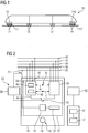
- FIG. 1 shows a trained as a traction vehicle rail vehicle 10 in a highly schematic side view. It has running axles 12 and drive axles 14, which are driven in a traction mode by means of drive units 16, 116.
- a braking operation of the rail vehicle 10 takes place by means of the drive units 16, 116, which each have the function of an electrodynamic brake.
- a further braking device 17, 117 is provided in each case, which is designed as a parking brake designed in the form of a spring brake, shown schematically in the figure.
- the control of the drive unit 16 as part of an electrodynamic brake is based on the FIG. 2 explained in more detail.
- the drive unit 16 has at least one drive motor 18, which may be designed as a three-phase machine.
- the drive unit 16 further comprises a power supply unit 20 operatively connected to the drive motor 18.
- the drive unit 16 may comprise a plurality of drive motors supplied by the same power supply unit 20.
- the power supply unit 20 is known from the prior art and has a non-illustrated inverter, which in a traction mode of the drive unit 16 generated by the control of electronic switching elements - also called "valves" - starting from a DC voltage intermediate circuit in voltage and frequency variable current according to the power to be provided for the drive motor 18.
- the energy available in the DC voltage intermediate circuit is obtained from a high-voltage power supply 26, which is in operative connection with a railway power supply via further electrical conversion devices, not shown, such as, in particular, a transformer or a voltage converter, a rectifier.
- the switching elements of the inverter are controlled according to a switching strategy to generate a drive torque to the associated drive axles 14 via the drive motor 18.
- the drive motor 18 forms, together with a brake control unit 22, an electrodynamic brake 24.
- the brake control unit 22 comprises, in addition to the power supply unit 20, two brake control units 28 and 30 which are respectively provided to control the power supply unit 20 for a braking operation of the electrodynamic brake 24 in an active state ,
- the brake control units 28, 30 are each provided to control in a braking mode of the drive unit 16, the switching elements of the inverter of the power supply unit 20 according to a switching strategy such that via the drive motor 18, a braking torque is exerted on the associated drive axle 14.
- the drive motor 18 acts as a generator, wherein the energy converted into electrical current in the braking process is converted into heat by means of a braking resistor 31.
- the energy may be fed back into the high voltage power supply 26, used on the vehicle or stored in a mobile memory.
- the first brake control unit 28 is in operative connection with the power supply unit 20 via a switching unit 32, whose function will be explained below.
- the brake control unit 28 further interfaces, through which it is in operative connection with a sensor unit 34.
- the sensor unit 34 serves to detect a speed parameter v and a mass parameter m, which represent input signals for the generation of control signals by the brake control unit 28.
- the brake control unit 28 is also operatively connected to the rail vehicle control system via further interfaces by being connected to a data bus 36 of the rail vehicle 10 and to the rail vehicle main air line 38.
- Further input parameters for the brake control unit 28 can be provided via these further interfaces, in particular a characteristic which, in the case of service braking, represents a braking effect set by the vehicle driver or by an automatic vehicle control system.
- the brake control unit 28 is supplied via an onboard power supply 40 with electrical energy and is also connected via an interface 41 with a vehicle emergency brake line 42 in operative connection, via which an emergency braking of the rail vehicle 10 can be initiated.
- the brake control unit 28 On the basis of the input parameters mentioned above, the brake control unit 28 generates control signals 44 in a first braking mode in which it is in an active state, which controls the power supply unit 20 according to a specific braking effect to be achieved, in particular in accordance with a specific braking torque to be achieved ,
- the operation control unit 28 has at least one computing unit 46 and a memory unit 48 in which software is stored.
- the brake mode switching strategy is programmed for the switching elements of the inverter.
- the brake control unit 28 is associated with a first brake action monitoring unit 50 of a first brake monitoring device 53, which is provided to the achieved or achievable by means of the electrodynamic brake 24 braking effect to monitor.
- a braking effect parameter in particular a braking torque characteristic
- the braking performance parameter can be detected, for example, by means of an acceleration sensor and / or determined by means of an evaluation of the speed parameter v.
- the braking performance characteristic can be determined by monitoring the control signals 44 generated by the brake control unit 28.
- An exemplary detection of the braking effect characteristic, which is denoted by reference B1 is in FIG. 3 represented schematically by a sensor unit 58 or 158.
- the brake control unit 22 comprises-as already mentioned above-a second brake control unit 30. This is intended to execute at least the control function described above for the first brake control unit 28 for controlling the power supply unit 20 in a second braking mode of the drive unit 16. In particular, it serves to take over the control of the power supply unit 20 in the event of faulty operation of the first brake control unit 28.
- the brake control unit 28 If it is detected by means of the first brake action monitoring unit 50 that the braking effect generated or achievable by the electrodynamic brake 24 is insufficient, the brake control unit 28 is regarded as faulty and it is switched as a fallback measure by the switching unit 32 into a second braking mode of the electrodynamic brake 24, in FIG wherein the second brake control unit 30 in its active state controls the power supply unit 20 to provide a braking action. In this second braking mode, the first faulty brake control unit 28 is switched to an inactive state.
- the second brake control unit 30 is assigned a second brake action monitoring unit 52 of the brake monitoring device 53.
- the braking effect monitoring units 50, 52 may be formed by physically separate units or they may be at least partially formed by a common structure. In particular, the braking effect monitoring units 50, 52 may be formed entirely by the same structure.
- the second brake action monitoring unit 52 is provided to monitor the braking effect achieved or achievable by means of the electrodynamic brake 24 in its second braking mode with the second brake control unit 30.
- a brake performance parameter in particular a brake torque parameter, is detected or determined and compared with a desired value.
- This braking effect characteristic may correspond in particular to the braking effect characteristic B1.
- the brake control unit 30 is regarded as defective and the further braking device 17 is made as a fallback measure by means of a switching device 54 controlled by the second brake action monitoring unit 52 ,
- the brake control units 28, 30 are based on different technologies. Under a technology, the constructive - or hardware - technical and / or the algorithmic - or software technical - execution is detected.
- the first brake control unit 28 may be in the form of a signal processor (also called "SIP"), where the algorithmic implementation may correspond to field-oriented control.
- the second brake control unit 30 may be implemented as a field programmable gate array (FPGA) or "field programmable gate array.” may be, wherein the algorithmic implementation may correspond to a switching-oriented scheme.
- FPGA field programmable gate array
- the second brake control unit 30 is designed in such a way that the control of the power supply unit 20 is performed exclusively by hardware-implemented functionality - without software deployment - while the first brake control unit 28 is based on a hardware and software implementation of the control functions.
- both brake control units 28, 30 are based on a software implementation with regard to at least one control function, the corresponding softwares are implemented differently in the brake control units 28, 30.
- the programming codes provided for executing the control function are different in that the codes, e.g. created by different people and / or different tools.
- the switching elements of the inverter of the power supply unit 20 are controlled by the first brake control unit 28 according to a first shift strategy and by the second brake control unit 30 according to a second, different from the first shift strategy switching strategy.
- the switching unit 32 assigned to the drive unit 16 is examined for functionality at regular and sufficiently short time intervals. For example, at standstill of the rail vehicle 10, for example during the upgrade or the brake test, the control of the switching elements of the inverter according to a specific test pattern by one of the brake control units 28, 30 generated.
- at least one sensor unit is provided which, for example, is a phase-current converter and / or has a DC link voltage converter and which detects an effect of the drive.
- the second brake control unit 30 is switched to its active state by means of the switching unit 32 and the test is repeated, preferably with a different test pattern. If an expected implementation of the respective test pattern is detected, the switching unit 32 is considered error-free.
- the above description also applies to the drive unit 116, which is part of a second electrodynamic brake 124 of the rail vehicle 10.
- the power supply unit of the drive unit 116 forms with brake control units 128, 130 a brake control unit 122, as in FIG FIG. 3 shown.
- the brake control units 22, 122 of the rail vehicle 10, each with their brake control units and their power supply unit, are designed so that they can effect an emergency braking by means of their associated drive motors 18 on the drive axles 14 of the rail vehicle 10 in cooperation.
- the brake control units 22, 122 are designed to generate, in cooperation with one another, a braking torque which is necessary for carrying out emergency braking, at least on the drive axles 14.
- FIG. 3 shows on the left side of the drive unit 16, which as described above comprises at least the drive motor 18 and the power supply unit 20 (see FIG. 2 ).
- the brake control units 28, 30 are also shown, which together with the power supply unit 20 form the brake control unit 22.
- the brake control unit 22 forms, together with the drive motor 18, the electrodynamic brake 24, which is referred to below as the "first electrodynamic brake 24".
- the brake control unit 22 has the switching unit 32, which is provided for performing a fallback action of the first brake 24, between the first brake mode of the brake control unit 22, in which the first brake control unit 28 controls the power supply unit 20 to provide a braking action, and a second brake mode To switch the brake control unit 22, in which the second brake control unit 30 controls the power supply unit 20 to provide a braking effect.
- FIG. 3 shows an actuator 33 for actuating the switching unit 32.
- the rail vehicle 10 has, as well as in FIG. 1 illustrated, the further drive unit 116 on.
- the drive unit 116 which, like the drive unit 16, comprises at least one drive motor and a power supply unit, is part of an electrodynamic brake 124, which is formed as far as possible, in particular completely identical to the electrodynamic brake 24. Therefore, to avoid unnecessary repetition, reference is made to the description above for the electrodynamic brake 24.
- the electrodynamic brake 124 which is referred to below as “second electrodynamic brake 124" includes the drive motor of the drive unit 116 and a brake control unit 122. This includes the power supply unit of the drive unit 116 and two brake control units 128, 130, which are each provided to control this power supply unit for a braking operation of the electrodynamic brake 124 in an active state.
- the brake control unit 122 has a switching unit 132 with actuator 133, which has the same function as the switching unit 32 in the first electrodynamic brake 24: It is provided for performing the respective fallback action between the first braking mode of the brake control unit 122, in which the first Brake control unit 128, the power supply unit of the drive unit 116 to provide controls a braking action, and to switch a second braking mode of the brake control unit 122, in which the second brake control unit 130 controls this power supply unit to provide a braking action.
- the first brake 24 associated brake monitoring device 53 is at least formed by the brake control unit 122 of the second brake 124.
- Brake monitoring device 53 shown is formed by the brake control units 128, 130 of the brake control unit 122 of the second brake 124 and by a further, separate from these monitoring unit 56.
- the brake monitoring device 53 is equipped with a first monitoring function, in particular programmed, in which this brake monitoring device 53 - in addition to the above-described control tasks of the brake control units 128, 130 for controlling the power supply unit of the drive unit 116 - is designed as a first brake action monitoring unit 50, which is intended to monitor first brake 24 in its first braking mode.
- This monitoring function is based on a monitoring task described below, which is performed by each of the brake control units 128, 130 and the monitoring unit 56 in parallel and largely, in particular completely independently. These units are each in operative connection with a sensor unit 58, which is provided for detecting or determining a first braking effect parameter B1 for the first braking mode of the first electrodynamic brake 24.
- the braking effect parameter B1 may in particular be a braking torque parameter, the sensor unit 58 being e.g. can be mechanically coupled with an axis 14 driven by the drive motor 18 and, for example, designed as a torque sensor.
- the sensor unit 58 is shown schematically and may consist of one or more sensors, wherein the sensor unit 58, the Brems Oberskennishish B1 of one or more measured sizes provides.
- a plurality of brake performance characteristics can be detected, which differ in their nature from each other and are each evaluated by a different unit of the brake monitoring device 53, as described in more detail below.
- the brake control units 28, 30 of the first brake 24 are based on different technologies. This applies correspondingly to the brake control units 128, 130. Under a technology, the constructive or hardware engineering and / or the algorithmic or software engineering execution is detected.
- the first brake control unit 128 may be in the form of a signal processor (also called "SIP"), the algorithmic implementation of which corresponds to a field-oriented control.
- the second brake control unit 130 can be designed as a field programmable gate array (FPGA) or "field programmable gate arrangement", the algorithmic implementation corresponding to a switching-oriented control.
- the second brake control unit 130 is designed in such a way that the control of the power supply unit of the drive unit 116 is carried out exclusively by means of hardware-implemented functionality - Without software use - takes place, while the first brake control unit 128 is based on a hardware and software implementation of the control functions.
- both brake control units 128, 130 are based on a software implementation with regard to at least one control function, the corresponding software is implemented differently in the brake control units 128, 130.
- the programming codes provided for executing the control function are different in that the codes, e.g. created by different people and / or different tools.
- each of the brake control units 128, 130 can monitor the braking action of the first brake 24 in its first braking mode according to an individual method different from the methods of the other brake control unit.
- the brake control units 128, 130 of the brake control unit 122 of the second brake 124 accordingly correspond in the execution of monitoring functions two monitoring devices 127, 129 of the brake monitoring device 53, which differ from each other by the features described above. In particular, they differ from one another with regard to their structural and / or algorithmic execution. If they each have software for performing monitoring functions, these software are implemented differently.
- the monitoring unit 56 is based on a technology that differs from the technologies of the brake control units 128, 130 and the monitoring devices 127, 129.
- the monitoring unit 56 based on the CPLD technology ("Complex Programmable Logic Device").
- the monitoring of the braking effect generated by the first brake 24 can therefore be done according to a method that differs from the methods of the brake control units 128, 130 and monitoring devices 127, 129.
- the monitoring task to be performed by each brake control unit 128, 130 and by the monitoring unit 56 is to determine whether the braking effect generated by the first brake 24 in its first braking mode is sufficient on the basis of the braking performance parameter B1. Due to the different technologies in the considered embodiment, the monitoring mechanism, with which the brake control units 128, 130 and the monitoring unit 56 are equipped to perform the first monitoring function, realized in each case in a different way or different in each of these units. In particular, the different monitoring mechanisms can be implemented by different monitoring software. The monitoring task is therefore each by means of a different method. by means of a different implementation of the task by these units largely separated, in particular completely separated done.
- a plurality of braking performance characteristics can be detected, which differ in their kind from one another and are each evaluated by a different unit of the brake monitoring device 53.
- the type of motion characteristics is determined by the technology of the respective unit of the brake monitoring device 53.
- the brake control units 128, 130 of the second brake 124 ie the monitoring devices 127, 129 and the monitoring unit 56 are each provided to issue an error signal in the execution of this monitoring task depending on the first braking effect characteristic B1 and the respective braking effect characteristic. This is output by each of these units when the evaluation of the braking effect parameter B1 or the respective braking effect characteristic results in the result by the respective unit that an insufficient braking effect of the first brake 24 in its first braking mode is considered to be recognized. Due to the different implementation of the monitoring task in each of the units mentioned, a largely independent, in particular completely independent, output of an error signal can take place by the units of the brake monitoring device 53.
- a trip unit 60 is used, which as part of the first brake monitoring device 53 is in operative connection with an output of the brake control units 128, 130 (or monitoring devices 127, 129) and the monitoring unit 56 on the one hand and with the switching unit 32, in particular with the actuator 33 on the other hand.
- the tripping unit 60 (also called “voter” device) has three lines connected in parallel to one another, which can be electrically connected to a common voltage source 62 and together with the actuator 33.
- each line two switches are arranged, wherein the switches during the execution of the monitoring task by the brake control units 128, 130 and the monitoring unit 56 - and thus in the first braking mode of the first brake 24 - are in an open position.
- an electrical connection between the voltage source 62 and the actuator 33 is disconnected.
- This electrical connection can be made by closing both switches in at least one line, whereby the switching unit 32 is actuated.
- the switches are each closed by means of an error signal which is present at the output of a unit of the brake monitoring device 53.
- the switches are each in operative connection with a different unit thereof, so that closing both switches in this line and therefore the operation of the switching unit 32 only take place when an error signal of two different Units of brake monitoring device 53 is output.
- the monitoring task namely the individual evaluation of the braking effect parameter B1 or of the respective braking effect parameter by the brake control units 128, 130 and the monitoring unit 56, as described above, is performed largely independently of these units.
- the monitoring function includes this monitoring task and is associated with the actuation of the switching unit 32 by cooperation of the units of the brake monitor 53, i. the monitoring devices 127, 129 and the monitoring unit 56, in particular by a combination of the results of the individual monitoring tasks done.
- the brake monitoring device 53 is equipped with a second monitoring function, in particular programmed, in which it - in addition to the above-described control tasks of the brake control units 128, 130 for controlling the power supply unit of the drive unit 116 - is designed as a second brake action monitoring unit 52 (see FIG. 2 ), which is intended to monitor the first brake 24 in its second braking mode.
- This second monitoring function is based on a monitoring task, which is performed by each of the brake control units 128, 130 and the monitoring unit 56 largely separated and is identical to the monitoring task of the first monitoring function.
- the second monitoring function differs from the first monitoring function by the use of a further trip unit 64, which as an integral part the brake monitoring device 53 with an output of the brake control units 128, 130 and the monitoring unit 56 on the one hand and with the switching device 54 (see also FIG. 2 ), in particular with the actuator 55 is in operative connection.
- Trip unit 64 also called a "voter” device
- Trip unit 64 has three series-connected pairs of parallel lines that are electrically connectable to common source 62 and common to actuator 55.
- a switch is arranged, wherein the switches during the execution of the monitoring task by the brake control units 128, 130 and the monitoring unit 56 - and thus during the second braking mode of the first brake 24 - are in a closed position.
- an electrical connection between the voltage source 62 and the actuator 55 is made.
- This electrical connection can be interrupted by opening both switches in at least one line pair, whereby the switching unit 54 is actuated.
- the switches are each opened by means of an error signal which is present at the output of a unit of the brake monitoring device 53.
- the switches are each in operative connection with a different unit thereof, so that an opening of both switches in this line pair and therefore the operation of the switching device 54 only take place when an error signal is output from two different units of the brake monitoring device 53.
- the switching unit 54 is in a closed position, whereby an electrical connection between a voltage source 66 and the braking device 17 is made.
- a signal "release the braking device 17" is set. If the switching unit 54 is actuated, this electrical connection is disconnected, whereby a signal "application of the braking device 17" is generated.
- a control line 67 is also shown, through which the braking device 17 can be actuated at any time by means of a command from the vehicle driver.
- the monitoring task namely the individual evaluation of the braking effect parameter B1 or of the respective braking effect characteristic by the brake control units 128, 130 and by the monitoring unit 56, as described above, is performed largely independently of these units.
- the monitoring function includes this monitoring task and is done with the operation of the switching unit 54 by an interaction of these units, in particular by a combination of the results of the individual monitoring tasks.
- a fallback action is initiated in insufficient braking action of the first electrodynamic brake 24 in the second braking mode, which corresponds to the above-described operation of the mechanical brake 17.
- the second braking mode should continue to act until the braking process is over.
- the trip unit 64 provided for the second monitoring function is inactive, by a permanent, independent of the configuration of the trip unit 64 electrical connection between the voltage source 62 and Actuator 55 is made.
- This electrical connection is interrupted at the transition to the second braking mode by a switch 68, which is opened by the actuator 33 when the switching unit 32 is actuated. The electrical connection then remains only on the trip unit 64, which is therefore placed in an active state.
- the trip unit 60 provided for the first monitoring function is inactive, by a permanent, independent of the configuration of the trip unit 60 electrical connection between a voltage source 70 and Actuator 33 is made.
- a reset unit 72 is also provided, which serves to take the first brake control unit 28 after the end of the second braking mode or after completion of a braking operation by means of the braking device 17 back into operation. This is done by means of a signal S which actuates an actuator 74, by means of which a switch 76 separates the electrical connection of the actuator 33 with the voltage source 70.
- the switching unit 32 is reset, so that the brake control unit 28 is again connected to the power supply unit 20 effectively;
- the switch 68 is actuated so that an electrical connection of the voltage source 62 is made with the actuator 55 and thereby the trip unit 64 are deactivated;
- a switch 78 disconnects an electrical connection between a voltage source 80 and the actuator 74, so that the reset unit 72 is deactivated or no actuation of the switch 76 by the actuator 74 by means of the signal S can take place. Actuation of the switch 78 to activate the reset unit 72 requires completion of the condition that led to the response of the monitoring.
- the first and second monitoring functions performed by the brake monitoring device 53 belong to a first monitoring mode of the braking device of the rail vehicle 10, in which the first brake 24 is monitored.
- a monitoring role for the initiation of one of the above-described fallback measures relating to the first brake 24 is assumed by the second brake 124, in particular by the brake control unit 122 thereof.
- the braking device of the rail vehicle 10 is provided with a second monitoring mode in which the second brake 124 is monitored.
- a monitoring role for the initiation of one of the above-described fallback measures concerning the second brake 124 from the first brake 24, in particular from the brake control unit 22 is assumed.
- the brake monitoring device 153 like the brake monitoring device 53, is provided with two monitoring functions, which are respectively provided for monitoring the second brake 124 during the execution of its first braking mode or second braking mode.
- the brake control units 28, 30 are formed in the execution of the monitoring functions as monitoring devices 27, 29 of the brake monitoring device 153.
- the brake monitoring device 153 is designed as a brake action monitoring unit 150 or 152 for the first or second braking mode of the brake control unit 122 of the second brake 124.
- This monitoring is carried out as a function of a second braking effect parameter B2 or of a plurality of braking effect characteristics which are different from each other in their type and which are detected by a sensor unit 158.
- the above description of the sensor unit 58 applies correspondingly to the sensor unit 158.
- the sensor units 58 and 158 may be at least partially formed of a same sensor structure with respect to hardware.
- FIG. 3 For the sake of clarity, is in FIG. 3 only the monitoring of the first brake 24 by the second brake 124 shown.
- the above description of the brake monitoring device 53 performed monitoring functions for the first brake 24 with respect to the monitoring of the second brake 124 corresponding application.
- the corresponding monitoring functions are performed by the brake control units 28, 30 in their function as monitoring devices 27, 29 in cooperation with the monitoring unit 56.
- the monitoring unit 56 is in the considered embodiment a common part of the first brake monitoring device 53 and the second brake monitoring device 153.
- the execution of the monitoring functions can be carried out in the brake control units 28, 30, 128, 130 in their function as monitoring devices 27, 29, 127, 129 each by means of a computing unit which is identical to or different from the computing unit, which provided for the execution of a braking mode is.
- a rail vehicle can be provided with an emergency brake device, with emergency braking can be done only by means of electrodynamic brakes with a sufficient level of security.
- This can advantageously be dispensed with a full-fledged, additional friction brake.
- a parking brake for example in the form of a spring-loaded brake, can be retained as a friction brake, which prevents the parked vehicle on a slope from rolling away due to frictional force generated by means of a spring accumulator. This can be a significant reduction the cost of brake components and the weight of the rail vehicle can be achieved.
- the drive units 16 and 116 may be associated with a same bogie of the rail vehicle 10 or separate bogies.
- the drive units 16, 116 are each associated with a different bogie.
- the drive axles 14 of a same bogie are each driven by a separate drive motor, both drive motors are powered by the same power supply unit.
- the electrodynamic brakes 24, 124 are each associated with different bogies and therefore several drive axles. Accordingly, by means of the brake monitoring devices 53, 153, a bogie-wise localization of a brake effect loss can be achieved and a fallback measure with respect to the respective bogie can be introduced in a differentiated manner.
- a drive motor is provided for each driven axle of a bogie, wherein for each drive motor of this bogie in each case a different power supply unit is provided.
- each driven axle of the bogie is associated with a separate electrodynamic brake.
- the electrodynamic brakes 24, 124 are assigned to a same bogie or each a different drive axle in this bogie. Accordingly, by means of the brake monitoring devices 53, 153 an axis-wise localization of a brake effect loss can be achieved and a fallback measure with respect to the respective drive axle can be initiated in a differentiated manner.
Landscapes
- Engineering & Computer Science (AREA)
- Mechanical Engineering (AREA)
- Transportation (AREA)
- Power Engineering (AREA)
- Electric Propulsion And Braking For Vehicles (AREA)
- Valves And Accessory Devices For Braking Systems (AREA)
- Regulating Braking Force (AREA)
- Braking Systems And Boosters (AREA)
- Braking Arrangements (AREA)
Priority Applications (1)
| Application Number | Priority Date | Filing Date | Title |
|---|---|---|---|
| PL13708749T PL2794338T3 (pl) | 2012-02-29 | 2013-02-28 | Urządzenie hamulcowe pojazdu szynowego i sposób hamowania pojazdu szynowego |
Applications Claiming Priority (2)
| Application Number | Priority Date | Filing Date | Title |
|---|---|---|---|
| DE102012203132A DE102012203132A1 (de) | 2012-02-29 | 2012-02-29 | Schienenfahrzeugbremsvorrichtung |
| PCT/EP2013/054057 WO2013127934A2 (de) | 2012-02-29 | 2013-02-28 | Schienenfahrzeugbremsvorrichtung und verfahren zum bremsen eines schienenfahrzeugs |
Publications (2)
| Publication Number | Publication Date |
|---|---|
| EP2794338A2 EP2794338A2 (de) | 2014-10-29 |
| EP2794338B1 true EP2794338B1 (de) | 2016-02-24 |
Family
ID=47845969
Family Applications (2)
| Application Number | Title | Priority Date | Filing Date |
|---|---|---|---|
| EP13708749.0A Active EP2794338B1 (de) | 2012-02-29 | 2013-02-28 | Schienenfahrzeugbremsvorrichtung und verfahren zum bremsen eines schienenfahrzeugs |
| EP13708754.0A Active EP2800672B2 (de) | 2012-02-29 | 2013-02-28 | Schienenfahrzeugbremsvorrichtung |
Family Applications After (1)
| Application Number | Title | Priority Date | Filing Date |
|---|---|---|---|
| EP13708754.0A Active EP2800672B2 (de) | 2012-02-29 | 2013-02-28 | Schienenfahrzeugbremsvorrichtung |
Country Status (13)
Families Citing this family (44)
| Publication number | Priority date | Publication date | Assignee | Title |
|---|---|---|---|---|
| DE102012203132A1 (de) | 2012-02-29 | 2013-08-29 | Siemens Aktiengesellschaft | Schienenfahrzeugbremsvorrichtung |
| EP2972601B1 (de) * | 2013-03-14 | 2019-07-03 | TTTech Auto AG | Verfahren zur risikoabgrenzung von fehlern in einem redundanten sicherheitsrelevanten steuerungssystem für ein kraftfahrzeug |
| AT14292U1 (de) * | 2013-04-15 | 2015-07-15 | Ve Vienna Engineering Forschungs Und Entwicklungs Gmbh | Verfahren zum Betätigen einer elektrisch betätigten Reibungsbremse |
| US11814088B2 (en) | 2013-09-03 | 2023-11-14 | Metrom Rail, Llc | Vehicle host interface module (vHIM) based braking solutions |
| US20150060608A1 (en) * | 2013-09-03 | 2015-03-05 | Metrom Rail, Llc | Rail Vehicle Signal Enforcement and Separation Control |
| ES2647845T5 (es) | 2013-09-26 | 2021-06-14 | Siemens Mobility GmbH | Método para el frenado de un vehículo ferroviario y dispositivo de control y/o de regulación para un sistema de frenado |
| DE102014203751A1 (de) * | 2014-02-28 | 2015-09-03 | Siemens Aktiengesellschaft | Fahrzeug, insbesondere Schienenfahrzeug, mit Bremsvermögensberechnungsmöglichkeit und Verfahren zu dessen Betrieb |
| DE102014214822A1 (de) * | 2014-07-29 | 2016-02-04 | Siemens Aktiengesellschaft | Bremsvorrichtung mit einer Bremse und Verfahren zum Steuern einer Bremse. |
| CN104494589B (zh) * | 2014-11-28 | 2016-12-07 | 中国北车集团大连机车车辆有限公司 | 铁路机车制动系统备用控制装置 |
| WO2016154295A1 (en) | 2015-03-23 | 2016-09-29 | Metrom Rail, Llc | Worker protection system |
| DE102015110053A1 (de) * | 2015-06-23 | 2016-12-29 | Knorr-Bremse Systeme für Schienenfahrzeuge GmbH | Bremssystem für ein Schienenfahrzeug |
| CN105015523B (zh) * | 2015-07-08 | 2017-10-20 | 中车南京浦镇车辆有限公司 | 一种动车组制动指令转换控制电路 |
| CN105083029B (zh) * | 2015-09-06 | 2017-11-03 | 哈尔滨工业大学 | 交流励磁轨道涡流制动器及其制动方法 |
| US10332708B2 (en) | 2015-12-09 | 2019-06-25 | Thales Canada Inc | Seamless switchover system and method |
| DE102015226831A1 (de) * | 2015-12-30 | 2017-07-06 | Siemens Aktiengesellschaft | Fahrzeug mit einer Bremseinrichtung |
| DE102016103352A1 (de) * | 2016-02-25 | 2017-08-31 | Knorr-Bremse Systeme für Schienenfahrzeuge GmbH | Verfahren und Vorrichtung zur Steuerung oder Regelung einer Bremsanlage |
| EP3216656B1 (de) * | 2016-03-08 | 2018-07-25 | Siemens Aktiengesellschaft | Schienenfahrzeug |
| JP6825945B2 (ja) * | 2016-05-10 | 2021-02-03 | シャープ株式会社 | モーター駆動式の走行装置 |
| CN106864267B (zh) * | 2017-03-10 | 2023-03-21 | 南昌工程学院 | 一种用于列车的自供电方法 |
| DE102017106118A1 (de) * | 2017-03-22 | 2018-09-27 | Knorr-Bremse Systeme für Schienenfahrzeuge GmbH | Bremsvorrichtung für Schienenfahrzeuge und Verfahren zum Bremsen von Schienenfahrzeugen |
| DE102017106119A1 (de) * | 2017-03-22 | 2018-09-27 | Knorr-Bremse Systeme für Schienenfahrzeuge GmbH | Bremsvorrichtung für Schienenfahrzeuge und Verfahren zum Bremsen von Schienenfahrzeugen |
| DE102017208887A1 (de) * | 2017-05-24 | 2018-11-29 | Knorr-Bremse Systeme für Schienenfahrzeuge GmbH | Elektropneumatische Bremseinrichtung mit sicherer Stromversorgung zur Realisierung einer Notbremsfunktion |
| US11349589B2 (en) | 2017-08-04 | 2022-05-31 | Metrom Rail, Llc | Methods and systems for decentralized rail signaling and positive train control |
| CN109383468B (zh) * | 2017-08-11 | 2020-09-15 | 比亚迪股份有限公司 | 列车控制方法及装置、列车 |
| DE102017217472B4 (de) * | 2017-09-29 | 2020-06-04 | Siemens Mobility GmbH | Konzept zum Übertragen einer Schnellbremsanforderung in einem Triebfahrzeug |
| CN109795518B (zh) * | 2017-11-17 | 2021-03-19 | 中车唐山机车车辆有限公司 | 一种轨道列车制动控制系统及列车 |
| DE102018208664A1 (de) * | 2018-05-31 | 2019-12-05 | Siemens Mobility GmbH | Überwachung einer elektrodynamischen Bremse in einem Schienenfahrzeug |
| CN108791259B (zh) * | 2018-05-31 | 2020-06-16 | 中车青岛四方机车车辆股份有限公司 | 列车冗余制动装置及方法 |
| IT201800007444A1 (it) * | 2018-07-23 | 2020-01-23 | Sistema di frenatura per un convoglio ferroviario. | |
| CN109131286B (zh) * | 2018-08-21 | 2021-02-05 | 中车株洲电力机车有限公司 | 一种冗余的列车乘客紧急制动控制装置及方法 |
| DE102018218296A1 (de) * | 2018-10-25 | 2020-04-30 | Siemens Mobility GmbH | Bremswiderstand für ein elektrisch angetriebenes Fahrzeug |
| DE102019129328A1 (de) * | 2019-10-30 | 2021-05-06 | Knorr-Bremse Systeme für Schienenfahrzeuge GmbH | Verfahren zur Schnellbremsung eines Schienenfahrzeugs mit definierten Bremsvorgaben |
| CN111301477B (zh) * | 2019-12-12 | 2021-04-06 | 罗冬 | 一种火车刹车辅助设备 |
| CN112224029B (zh) * | 2020-10-15 | 2022-04-12 | 中车青岛四方车辆研究所有限公司 | 轨道车辆的电子机械制动系统的冗余控制方法 |
| EP4011718B1 (en) * | 2020-12-09 | 2024-06-05 | KNORR-BREMSE Systeme für Schienenfahrzeuge GmbH | Brake assembly |
| US11999267B2 (en) | 2021-01-20 | 2024-06-04 | Abb Schweiz Ag | Power line system with ripple generator for electric vehicles |
| CN112706740B (zh) * | 2021-02-24 | 2021-12-17 | 中车株洲电力机车有限公司 | 一种机车及其紧急制动时制动缸压力控制系统与方法 |
| DE102022203764A1 (de) | 2022-04-13 | 2023-10-19 | Knorr-Bremse Systeme für Schienenfahrzeuge GmbH | Bremssystem und Bremsverfahren für Schienenfahrzeuge |
| DE102022203765A1 (de) * | 2022-04-13 | 2023-10-19 | Knorr-Bremse Systeme für Schienenfahrzeuge GmbH | Bremssystem und Bremsverfahren für Schienenfahrzeuge |
| DE102022203763A1 (de) | 2022-04-13 | 2023-10-19 | Knorr-Bremse Systeme für Schienenfahrzeuge GmbH | Bremssystem und Bremsverfahren für Schienenfahrzeuge |
| DE102022204252A1 (de) | 2022-04-29 | 2023-11-02 | Siemens Mobility GmbH | Verfahren zum Steuern einer elektrodynamischen Bremsvorrichtung eines Schienenfahrzeugs |
| CN115214592B (zh) * | 2022-07-13 | 2024-05-10 | 北京主导时代科技有限公司 | 一种轨道车辆制动机检测装置 |
| DE102023122397B4 (de) * | 2023-08-22 | 2025-07-31 | Sick Ag | Sicherheitssystem für ein Fahrzeug und Verfahren mit einem Sicherheitssystem für ein Fahrzeug |
| DE102023209050A1 (de) * | 2023-09-18 | 2025-03-20 | Knorr-Bremse Systeme für Schienenfahrzeuge GmbH | Funktionseinheit mit Rückfallbetriebsmodus für ein Betriebssystem eines Schienenfahrzeugs |
Citations (15)
| Publication number | Priority date | Publication date | Assignee | Title |
|---|---|---|---|---|
| DE19615805A1 (de) | 1996-04-20 | 1997-10-23 | Bosch Gmbh Robert | Verfahren und Vorrichtung zur Steuerung der Bremsanlage eines Fahrzeugs |
| US5924774A (en) | 1995-11-30 | 1999-07-20 | Zeftron, Inc. | Electronic pneumatic brake system |
| EP1195286A2 (de) | 2000-10-05 | 2002-04-10 | Siemens Aktiengesellschaft | Verfahren zum Überwachen einer Bremse und Verfahren zum Bremsen einer Lokomotive |
| DE10160619A1 (de) | 2000-12-18 | 2002-07-11 | Toyota Motor Co Ltd | Fahrzeugbrems-Steuerungs/Regelungs-Verfahren und -Vorrichtung |
| EP1266814A2 (de) | 2001-06-15 | 2002-12-18 | Knorr-Bremse Systeme für Schienenfahrzeuge GmbH | Bremssystem für Schienenfahrzeuge |
| US20040054450A1 (en) | 2002-09-13 | 2004-03-18 | Nissan Motor Co., Ltd. | Coordinated brake control system |
| DE102006043892A1 (de) | 2006-09-19 | 2008-03-27 | Siemens Ag | Verfahren und Einrichtung zum Bremsen eines Schienenfahrzeuges |
| WO2008052696A1 (de) | 2006-10-31 | 2008-05-08 | Knorr-Bremse Systeme für Schienenfahrzeuge GmbH | Verfahren zum generatorischen bremsen eines schienenfahrzeugs mit unterlegtem passivem ersatzbremskreis und vorrichtung zur ausführung des verfahrens |
| EP2033835A2 (fr) | 2007-09-04 | 2009-03-11 | Alstom Transport S.A. | Dispositif sécuritaire de détection d'insuffisance de freinage électrique et de commutation sur un frein sécuritaire |
| EP2060459A1 (de) | 2007-11-16 | 2009-05-20 | Siemens Aktiengesellschaft | Bremsanlage für ein Schienenfahrzeug und Verfahren zum Abbremsen des Schienenfahrzeugs und Bremssteuerung für eine derartige Bremsanlage |
| DE102008018873A1 (de) | 2008-04-14 | 2009-10-15 | Bombardier Transportation Gmbh | Steuerung für ein Fahrzeug |
| DE102008027520A1 (de) | 2008-06-10 | 2010-01-14 | Siemens Aktiengesellschaft | Verfahren für ein Schienenfahrzeug zur Anforderung von Sicherheitsreaktionen |
| WO2011036003A2 (de) | 2009-09-23 | 2011-03-31 | Siemens Aktiengesellschaft | Bremssystem mit intelligentem aktuator zum abbremsen eines schienengeführten fahrzeugs |
| US20120000739A1 (en) | 2009-03-13 | 2012-01-05 | Kabushiki Kaisha Toshiba | Rolling stock system and control method thereof |
| US20120031692A1 (en) | 2010-08-05 | 2012-02-09 | Honda Motor Co., Ltd. | Vehicle braking system |
Family Cites Families (24)
| Publication number | Priority date | Publication date | Assignee | Title |
|---|---|---|---|---|
| SU709416A1 (ru) * | 1977-11-28 | 1980-01-15 | Egnus Aleksandr E | Устройство дл электрического торможени электроподвижного состава посто нного тока |
| GB8403721D0 (en) † | 1984-02-13 | 1984-03-14 | Westinghouse Brake & Signal | Brake control system |
| US4671577A (en) † | 1985-11-21 | 1987-06-09 | Urban Transportation Development Corporation Ltd. | Combined regenerative and friction braking system for a vehicle |
| US5517093A (en) | 1993-12-16 | 1996-05-14 | General Electric Company | Braking grid isolation for locomotive traction motor control system |
| DE4423692A1 (de) * | 1994-07-06 | 1996-01-11 | Abb Patent Gmbh | Verfahren zur Überbrückung von Lücken in der Stromversorgung von elektrischen Schienenfahrzeugen |
| US5828979A (en) * | 1994-09-01 | 1998-10-27 | Harris Corporation | Automatic train control system and method |
| DE19510755C2 (de) † | 1995-03-24 | 1998-09-17 | Abb Patent Gmbh | Bremsanordnung für ein mehrere Bremssysteme aufweisendes schienengebundenes Triebfahrzeug |
| US6554088B2 (en) * | 1998-09-14 | 2003-04-29 | Paice Corporation | Hybrid vehicles |
| HUP0103977A3 (en) * | 1998-10-23 | 2002-03-28 | Knorr Bremse Systeme | Brake system for railway vehicles |
| DE10004430C2 (de) † | 2000-02-02 | 2001-12-06 | Siemens Ag | Bremsüberwachungsanordnung für ein Fahrzeug mit mehreren Bremssystemen |
| JP2001251701A (ja) | 2000-03-06 | 2001-09-14 | Hitachi Ltd | 電気車の制御装置 |
| US6964460B2 (en) * | 2003-12-03 | 2005-11-15 | Delphi Technologies, Inc. | Brake controller and method for controlling a brake system |
| WO2005073045A1 (de) * | 2004-02-02 | 2005-08-11 | Lucas Automotive Gmbh | Bremskrafterzeuger für eine hydraulische fahrzeugbremsanlage |
| DE602005017098D1 (de) * | 2004-07-21 | 2009-11-26 | Nissan Motor | Verfahren und Vorrichtung zum Steuern des Drehmoments eines Elektromotors für ein Kraftfahrzeug |
| DE102006011963B3 (de) † | 2006-02-23 | 2007-08-30 | Siemens Ag | Verfahren zum Bremsen eines Schienenfahrzeuges |
| ITTO20060735A1 (it) * | 2006-10-13 | 2008-04-14 | St Microelectronics Srl | Sistema e metodo di controllo autoadattativo di un freno elettromeccanico |
| US8180544B2 (en) * | 2007-04-25 | 2012-05-15 | General Electric Company | System and method for optimizing a braking schedule of a powered system traveling along a route |
| DE102008012957A1 (de) * | 2008-03-06 | 2009-09-10 | Repower Systems Ag | Verfahren zum Betreiben einer Windenergieanlage und Windenergieanlage |
| JP4643670B2 (ja) | 2008-03-07 | 2011-03-02 | 株式会社東芝 | 電気車駆動装置 |
| US20100256843A1 (en) * | 2009-04-02 | 2010-10-07 | Lookheed Martin Corporation | System for Vital Brake Interface with Real-Time Integrity Monitoring |
| DE102010005938A1 (de) * | 2010-01-26 | 2011-07-28 | Voith Patent GmbH, 89522 | Vorrichtung zur Steuerung oder Regelung von sicherheitsgerichteten Funktionen |
| US8630760B2 (en) * | 2010-08-09 | 2014-01-14 | GM Global Technology Operations LLC | Method for managing transitions in internal combustion engines with a hybrid drive powertrain |
| RU116413U1 (ru) * | 2011-12-09 | 2012-05-27 | Закрытое акционерное общество "Кронид-ЭЛ" | Устройство для автоматического управления электрическим реостатным тормозом электровоза переменного тока |
| DE102012203132A1 (de) † | 2012-02-29 | 2013-08-29 | Siemens Aktiengesellschaft | Schienenfahrzeugbremsvorrichtung |
-
2012
- 2012-02-29 DE DE102012203132A patent/DE102012203132A1/de not_active Ceased
-
2013
- 2013-02-28 EP EP13708749.0A patent/EP2794338B1/de active Active
- 2013-02-28 CN CN201380011767.8A patent/CN104144811B/zh active Active
- 2013-02-28 ES ES13708749T patent/ES2572269T3/es active Active
- 2013-02-28 CA CA2865743A patent/CA2865743A1/en not_active Abandoned
- 2013-02-28 ES ES13708754T patent/ES2601955T5/es active Active
- 2013-02-28 CA CA2865748A patent/CA2865748A1/en not_active Abandoned
- 2013-02-28 IN IN6477DEN2014 patent/IN2014DN06477A/en unknown
- 2013-02-28 AU AU2013224976A patent/AU2013224976B2/en not_active Ceased
- 2013-02-28 CN CN201380011854.3A patent/CN104144813B/zh active Active
- 2013-02-28 EP EP13708754.0A patent/EP2800672B2/de active Active
- 2013-02-28 DK DK13708749.0T patent/DK2794338T3/en active
- 2013-02-28 PT PT137087540T patent/PT2800672T/pt unknown
- 2013-02-28 US US14/382,061 patent/US9707951B2/en active Active
- 2013-02-28 AU AU2013224984A patent/AU2013224984B2/en not_active Ceased
- 2013-02-28 PL PL13708749T patent/PL2794338T3/pl unknown
- 2013-02-28 WO PCT/EP2013/054057 patent/WO2013127934A2/de active Application Filing
- 2013-02-28 US US14/382,066 patent/US9533668B2/en active Active
- 2013-02-28 RU RU2014139061/11A patent/RU2586943C2/ru active
- 2013-02-28 IN IN6870DEN2014 patent/IN2014DN06870A/en unknown
- 2013-02-28 RU RU2014138813/11A patent/RU2587290C2/ru active
- 2013-02-28 WO PCT/EP2013/054074 patent/WO2013127942A2/de active Application Filing
Patent Citations (15)
| Publication number | Priority date | Publication date | Assignee | Title |
|---|---|---|---|---|
| US5924774A (en) | 1995-11-30 | 1999-07-20 | Zeftron, Inc. | Electronic pneumatic brake system |
| DE19615805A1 (de) | 1996-04-20 | 1997-10-23 | Bosch Gmbh Robert | Verfahren und Vorrichtung zur Steuerung der Bremsanlage eines Fahrzeugs |
| EP1195286A2 (de) | 2000-10-05 | 2002-04-10 | Siemens Aktiengesellschaft | Verfahren zum Überwachen einer Bremse und Verfahren zum Bremsen einer Lokomotive |
| DE10160619A1 (de) | 2000-12-18 | 2002-07-11 | Toyota Motor Co Ltd | Fahrzeugbrems-Steuerungs/Regelungs-Verfahren und -Vorrichtung |
| EP1266814A2 (de) | 2001-06-15 | 2002-12-18 | Knorr-Bremse Systeme für Schienenfahrzeuge GmbH | Bremssystem für Schienenfahrzeuge |
| US20040054450A1 (en) | 2002-09-13 | 2004-03-18 | Nissan Motor Co., Ltd. | Coordinated brake control system |
| DE102006043892A1 (de) | 2006-09-19 | 2008-03-27 | Siemens Ag | Verfahren und Einrichtung zum Bremsen eines Schienenfahrzeuges |
| WO2008052696A1 (de) | 2006-10-31 | 2008-05-08 | Knorr-Bremse Systeme für Schienenfahrzeuge GmbH | Verfahren zum generatorischen bremsen eines schienenfahrzeugs mit unterlegtem passivem ersatzbremskreis und vorrichtung zur ausführung des verfahrens |
| EP2033835A2 (fr) | 2007-09-04 | 2009-03-11 | Alstom Transport S.A. | Dispositif sécuritaire de détection d'insuffisance de freinage électrique et de commutation sur un frein sécuritaire |
| EP2060459A1 (de) | 2007-11-16 | 2009-05-20 | Siemens Aktiengesellschaft | Bremsanlage für ein Schienenfahrzeug und Verfahren zum Abbremsen des Schienenfahrzeugs und Bremssteuerung für eine derartige Bremsanlage |
| DE102008018873A1 (de) | 2008-04-14 | 2009-10-15 | Bombardier Transportation Gmbh | Steuerung für ein Fahrzeug |
| DE102008027520A1 (de) | 2008-06-10 | 2010-01-14 | Siemens Aktiengesellschaft | Verfahren für ein Schienenfahrzeug zur Anforderung von Sicherheitsreaktionen |
| US20120000739A1 (en) | 2009-03-13 | 2012-01-05 | Kabushiki Kaisha Toshiba | Rolling stock system and control method thereof |
| WO2011036003A2 (de) | 2009-09-23 | 2011-03-31 | Siemens Aktiengesellschaft | Bremssystem mit intelligentem aktuator zum abbremsen eines schienengeführten fahrzeugs |
| US20120031692A1 (en) | 2010-08-05 | 2012-02-09 | Honda Motor Co., Ltd. | Vehicle braking system |
Non-Patent Citations (2)
| Title |
|---|
| J-H LEE ET AL.: "Design of on-board computer system for Korean High-Speed Train", COMPUTERS IN RAILWAYS VII;, 2000, pages 933 - 941, XP055327347, ISBN: 1-85312-826-0 |
| LIONGINAS LIUDVINAVICIUS ET AL.: "Electrodynamic Braking in High-Speed Rail Transport;", TRANSPORT, vol. XXII, no. 3, 2007, pages 178 - 186, XP055327352 |
Also Published As
Similar Documents
| Publication | Publication Date | Title |
|---|---|---|
| EP2794338B1 (de) | Schienenfahrzeugbremsvorrichtung und verfahren zum bremsen eines schienenfahrzeugs | |
| EP3600994B1 (de) | Elektronisch steuerbares bremssystem sowie verfahren zum steuern des elektronisch steuerbaren bremssystems mit rein elektrischem bremswertgeber | |
| EP0780276B1 (de) | Bremsanlage für ein Kraftfahrzeug | |
| EP3172078B1 (de) | Stromübertragungssystem und verfahren zum betreiben eines stromübertragungssystems | |
| EP2909068B1 (de) | Stromversorgungseinrichtung für ein schienenfahrzeug | |
| EP3600992A1 (de) | Elektronisch steuerbares bremssystem sowie verfahren zum steuern des elektronisch steuerbaren bremssystems | |
| WO2018172268A1 (de) | Elektronisch steuerbares bremssystem sowie verfahren zum steuern des elektronisch steuerbaren bremssystems | |
| EP3670277B1 (de) | Bremssystem für ein kraftfahrzeug und kraftfahrzeug mit einem solchen bremssystem | |
| EP3371012B1 (de) | Fahrzeug mit einer bremseinrichtung | |
| DE102011113083A1 (de) | Bremssteuereinrichtung für eine Bremsanlage eines Schienenfahrzeuges, Bremsanlage, Schienenfahrzeug und Verfahren zum Durchführen einer Funktionsdiagnose | |
| DE19814657C2 (de) | Steuer- und/oder Regelvorrichtung für eine elektrische Feststellbremseinrichtung von Fahrzeugen | |
| DE102021108523A1 (de) | Bremssystem für ein autonomes Fahrzeug | |
| EP0830998A1 (de) | Elektrische Bremsanlage und Verfahren zum Betreiben einer elektrischen Bremsanlage | |
| DE102007043578A1 (de) | Verfahren und Vorrichtung zur Rückgewinnung von kinetischer Energie eines bewegten Fahrzeuges zur Versorgung sicherheitsrelevanter Fahrzeugfunktionen | |
| EP3634823B1 (de) | Vorrichtung mit einer antriebssteuereinrichtung, fahrzeug mit einer derartigen vorrichtung und verfahren zum betreiben einer antriebssteuereinrichtung | |
| WO2019053284A1 (de) | Fahrzeug mit elektrischer antriebseinrichtung, insbesondere für autonomes fahren, sowie verfahren zum ansteuern von antriebs- und lenkeinrichtungen in einem derartigen fahrzeug | |
| DE102022203853A1 (de) | Verfahren und Vorrichtung zum Abbremsen eines Fahrzeugs bei Ausfall der Bremsensteuerung | |
| EP4507939A1 (de) | Bremssystem und bremsverfahren für ein schienenfahrzeug | |
| WO2008012112A2 (de) | Zugbremssteuerungssystem mit verbesserter schnellbremssteuerung | |
| DE102019000422A1 (de) | Verfahren zum Test eines Antriebssystems mit einer Ersten Bremse und Antriebssystem | |
| DE102023130893A1 (de) | Bremsmodul für eine elektromechanische Bremse eines Fahrzeugs mit einem elektrischen Antrieb sowie Fahrzeug damit und Verfahren dafür | |
| WO2025061502A1 (de) | Funktionseinheit mit rückfallbetriebsmodus für ein bremssystem eines schienenfahrzeugs | |
| DE102021205120A1 (de) | Antriebseinheit für ein elektrisches Antriebssystem, elektrisches Antriebssystem sowie Verfahren zum Betreiben einer Antriebseinheit eines elektrischen Antriebssystems | |
| WO2024170189A1 (de) | Bremssystem mit energieversorgungssystem mit kombinierten energiespeicherarten zum betrieb von zumindest teilweise elektrisch betriebenen reibungsbremsstellern bei schienenfahrzeugen | |
| EP4507934A1 (de) | Bremssystem und bremsverfahren für schienenfahrzeuge |
Legal Events
| Date | Code | Title | Description |
|---|---|---|---|
| PUAI | Public reference made under article 153(3) epc to a published international application that has entered the european phase |
Free format text: ORIGINAL CODE: 0009012 |
|
| 17P | Request for examination filed |
Effective date: 20140724 |
|
| AK | Designated contracting states |
Kind code of ref document: A2 Designated state(s): AL AT BE BG CH CY CZ DE DK EE ES FI FR GB GR HR HU IE IS IT LI LT LU LV MC MK MT NL NO PL PT RO RS SE SI SK SM TR |
|
| DAX | Request for extension of the european patent (deleted) | ||
| GRAP | Despatch of communication of intention to grant a patent |
Free format text: ORIGINAL CODE: EPIDOSNIGR1 |
|
| INTG | Intention to grant announced |
Effective date: 20150825 |
|
| GRAS | Grant fee paid |
Free format text: ORIGINAL CODE: EPIDOSNIGR3 |
|
| GRAA | (expected) grant |
Free format text: ORIGINAL CODE: 0009210 |
|
| REG | Reference to a national code |
Ref country code: FR Ref legal event code: PLFP Year of fee payment: 4 |
|
| AK | Designated contracting states |
Kind code of ref document: B1 Designated state(s): AL AT BE BG CH CY CZ DE DK EE ES FI FR GB GR HR HU IE IS IT LI LT LU LV MC MK MT NL NO PL PT RO RS SE SI SK SM TR |
|
| REG | Reference to a national code |
Ref country code: GB Ref legal event code: FG4D Free format text: NOT ENGLISH |
|
| REG | Reference to a national code |
Ref country code: CH Ref legal event code: EP |
|
| REG | Reference to a national code |
Ref country code: AT Ref legal event code: REF Ref document number: 776498 Country of ref document: AT Kind code of ref document: T Effective date: 20160315 |
|
| REG | Reference to a national code |
Ref country code: IE Ref legal event code: FG4D Free format text: LANGUAGE OF EP DOCUMENT: GERMAN |
|
| REG | Reference to a national code |
Ref country code: CH Ref legal event code: NV Representative=s name: SIEMENS SCHWEIZ AG, CH |
|
| REG | Reference to a national code |
Ref country code: DE Ref legal event code: R096 Ref document number: 502013001999 Country of ref document: DE |
|
| REG | Reference to a national code |
Ref country code: DK Ref legal event code: T3 Effective date: 20160509 |
|
| REG | Reference to a national code |
Ref country code: ES Ref legal event code: FG2A Ref document number: 2572269 Country of ref document: ES Kind code of ref document: T3 Effective date: 20160531 |
|
| REG | Reference to a national code |
Ref country code: LT Ref legal event code: MG4D |
|
| REG | Reference to a national code |
Ref country code: NL Ref legal event code: MP Effective date: 20160224 |
|
| PG25 | Lapsed in a contracting state [announced via postgrant information from national office to epo] |
Ref country code: NO Free format text: LAPSE BECAUSE OF FAILURE TO SUBMIT A TRANSLATION OF THE DESCRIPTION OR TO PAY THE FEE WITHIN THE PRESCRIBED TIME-LIMIT Effective date: 20160524 Ref country code: GR Free format text: LAPSE BECAUSE OF FAILURE TO SUBMIT A TRANSLATION OF THE DESCRIPTION OR TO PAY THE FEE WITHIN THE PRESCRIBED TIME-LIMIT Effective date: 20160525 Ref country code: FI Free format text: LAPSE BECAUSE OF FAILURE TO SUBMIT A TRANSLATION OF THE DESCRIPTION OR TO PAY THE FEE WITHIN THE PRESCRIBED TIME-LIMIT Effective date: 20160224 Ref country code: HR Free format text: LAPSE BECAUSE OF FAILURE TO SUBMIT A TRANSLATION OF THE DESCRIPTION OR TO PAY THE FEE WITHIN THE PRESCRIBED TIME-LIMIT Effective date: 20160224 |
|
| PG25 | Lapsed in a contracting state [announced via postgrant information from national office to epo] |
Ref country code: LT Free format text: LAPSE BECAUSE OF FAILURE TO SUBMIT A TRANSLATION OF THE DESCRIPTION OR TO PAY THE FEE WITHIN THE PRESCRIBED TIME-LIMIT Effective date: 20160224 Ref country code: SE Free format text: LAPSE BECAUSE OF FAILURE TO SUBMIT A TRANSLATION OF THE DESCRIPTION OR TO PAY THE FEE WITHIN THE PRESCRIBED TIME-LIMIT Effective date: 20160224 Ref country code: PT Free format text: LAPSE BECAUSE OF FAILURE TO SUBMIT A TRANSLATION OF THE DESCRIPTION OR TO PAY THE FEE WITHIN THE PRESCRIBED TIME-LIMIT Effective date: 20160624 Ref country code: LV Free format text: LAPSE BECAUSE OF FAILURE TO SUBMIT A TRANSLATION OF THE DESCRIPTION OR TO PAY THE FEE WITHIN THE PRESCRIBED TIME-LIMIT Effective date: 20160224 Ref country code: RS Free format text: LAPSE BECAUSE OF FAILURE TO SUBMIT A TRANSLATION OF THE DESCRIPTION OR TO PAY THE FEE WITHIN THE PRESCRIBED TIME-LIMIT Effective date: 20160224 Ref country code: NL Free format text: LAPSE BECAUSE OF FAILURE TO SUBMIT A TRANSLATION OF THE DESCRIPTION OR TO PAY THE FEE WITHIN THE PRESCRIBED TIME-LIMIT Effective date: 20160224 |
|
| PG25 | Lapsed in a contracting state [announced via postgrant information from national office to epo] |
Ref country code: EE Free format text: LAPSE BECAUSE OF FAILURE TO SUBMIT A TRANSLATION OF THE DESCRIPTION OR TO PAY THE FEE WITHIN THE PRESCRIBED TIME-LIMIT Effective date: 20160224 |
|
| REG | Reference to a national code |
Ref country code: DE Ref legal event code: R026 Ref document number: 502013001999 Country of ref document: DE |
|
| PG25 | Lapsed in a contracting state [announced via postgrant information from national office to epo] |
Ref country code: SM Free format text: LAPSE BECAUSE OF FAILURE TO SUBMIT A TRANSLATION OF THE DESCRIPTION OR TO PAY THE FEE WITHIN THE PRESCRIBED TIME-LIMIT Effective date: 20160224 Ref country code: SK Free format text: LAPSE BECAUSE OF FAILURE TO SUBMIT A TRANSLATION OF THE DESCRIPTION OR TO PAY THE FEE WITHIN THE PRESCRIBED TIME-LIMIT Effective date: 20160224 Ref country code: RO Free format text: LAPSE BECAUSE OF FAILURE TO SUBMIT A TRANSLATION OF THE DESCRIPTION OR TO PAY THE FEE WITHIN THE PRESCRIBED TIME-LIMIT Effective date: 20160224 |
|
| REG | Reference to a national code |
Ref country code: IE Ref legal event code: MM4A |
|
| PLBI | Opposition filed |
Free format text: ORIGINAL CODE: 0009260 |
|
| 26 | Opposition filed |
Opponent name: KNORR-BREMSE SYSTEME FUER SCHIENENFAHRZEUGE GMBH Effective date: 20161124 |
|
| PLAX | Notice of opposition and request to file observation + time limit sent |
Free format text: ORIGINAL CODE: EPIDOSNOBS2 |
|
| PG25 | Lapsed in a contracting state [announced via postgrant information from national office to epo] |
Ref country code: IE Free format text: LAPSE BECAUSE OF NON-PAYMENT OF DUE FEES Effective date: 20160228 |
|
| REG | Reference to a national code |
Ref country code: FR Ref legal event code: PLFP Year of fee payment: 5 |
|
| PG25 | Lapsed in a contracting state [announced via postgrant information from national office to epo] |
Ref country code: SI Free format text: LAPSE BECAUSE OF FAILURE TO SUBMIT A TRANSLATION OF THE DESCRIPTION OR TO PAY THE FEE WITHIN THE PRESCRIBED TIME-LIMIT Effective date: 20160224 Ref country code: BG Free format text: LAPSE BECAUSE OF FAILURE TO SUBMIT A TRANSLATION OF THE DESCRIPTION OR TO PAY THE FEE WITHIN THE PRESCRIBED TIME-LIMIT Effective date: 20160524 |
|
| PLBB | Reply of patent proprietor to notice(s) of opposition received |
Free format text: ORIGINAL CODE: EPIDOSNOBS3 |
|
| RAP2 | Party data changed (patent owner data changed or rights of a patent transferred) |
Owner name: SIEMENS AKTIENGESELLSCHAFT |
|
| PG25 | Lapsed in a contracting state [announced via postgrant information from national office to epo] |
Ref country code: MT Free format text: LAPSE BECAUSE OF FAILURE TO SUBMIT A TRANSLATION OF THE DESCRIPTION OR TO PAY THE FEE WITHIN THE PRESCRIBED TIME-LIMIT Effective date: 20160224 |
|
| REG | Reference to a national code |
Ref country code: CH Ref legal event code: PCOW Free format text: NEW ADDRESS: WERNER-VON-SIEMENS-STRASSE 1, 80333 MUENCHEN (DE) |
|
| REG | Reference to a national code |
Ref country code: DE Ref legal event code: R100 Ref document number: 502013001999 Country of ref document: DE |
|
| REG | Reference to a national code |
Ref country code: FR Ref legal event code: PLFP Year of fee payment: 6 |
|
| PLCK | Communication despatched that opposition was rejected |
Free format text: ORIGINAL CODE: EPIDOSNREJ1 |
|
| PG25 | Lapsed in a contracting state [announced via postgrant information from national office to epo] |
Ref country code: HU Free format text: LAPSE BECAUSE OF FAILURE TO SUBMIT A TRANSLATION OF THE DESCRIPTION OR TO PAY THE FEE WITHIN THE PRESCRIBED TIME-LIMIT; INVALID AB INITIO Effective date: 20130228 |
|
| PG25 | Lapsed in a contracting state [announced via postgrant information from national office to epo] |
Ref country code: LU Free format text: LAPSE BECAUSE OF NON-PAYMENT OF DUE FEES Effective date: 20160228 Ref country code: IS Free format text: LAPSE BECAUSE OF FAILURE TO SUBMIT A TRANSLATION OF THE DESCRIPTION OR TO PAY THE FEE WITHIN THE PRESCRIBED TIME-LIMIT Effective date: 20160224 Ref country code: MC Free format text: LAPSE BECAUSE OF FAILURE TO SUBMIT A TRANSLATION OF THE DESCRIPTION OR TO PAY THE FEE WITHIN THE PRESCRIBED TIME-LIMIT Effective date: 20160224 Ref country code: CY Free format text: LAPSE BECAUSE OF FAILURE TO SUBMIT A TRANSLATION OF THE DESCRIPTION OR TO PAY THE FEE WITHIN THE PRESCRIBED TIME-LIMIT Effective date: 20160224 Ref country code: MK Free format text: LAPSE BECAUSE OF FAILURE TO SUBMIT A TRANSLATION OF THE DESCRIPTION OR TO PAY THE FEE WITHIN THE PRESCRIBED TIME-LIMIT Effective date: 20160224 |
|
| PLBN | Opposition rejected |
Free format text: ORIGINAL CODE: 0009273 |
|
| STAA | Information on the status of an ep patent application or granted ep patent |
Free format text: STATUS: OPPOSITION REJECTED |
|
| 27O | Opposition rejected |
Effective date: 20180119 |
|
| PG25 | Lapsed in a contracting state [announced via postgrant information from national office to epo] |
Ref country code: AL Free format text: LAPSE BECAUSE OF FAILURE TO SUBMIT A TRANSLATION OF THE DESCRIPTION OR TO PAY THE FEE WITHIN THE PRESCRIBED TIME-LIMIT Effective date: 20160224 |
|
| REG | Reference to a national code |
Ref country code: DE Ref legal event code: R081 Ref document number: 502013001999 Country of ref document: DE Owner name: SIEMENS MOBILITY GMBH, DE Free format text: FORMER OWNER: SIEMENS AKTIENGESELLSCHAFT, 80333 MUENCHEN, DE |
|
| REG | Reference to a national code |
Ref country code: CH Ref legal event code: PUE Owner name: SIEMENS MOBILITY GMBH, DE Free format text: FORMER OWNER: SIEMENS AKTIENGESELLSCHAFT, DE |
|
| REG | Reference to a national code |
Ref country code: GB Ref legal event code: 732E Free format text: REGISTERED BETWEEN 20190207 AND 20190213 |
|
| REG | Reference to a national code |
Ref country code: AT Ref legal event code: PC Ref document number: 776498 Country of ref document: AT Kind code of ref document: T Owner name: SIEMENS MOBILITY GMBH, DE Effective date: 20190506 |
|
| REG | Reference to a national code |
Ref country code: BE Ref legal event code: PD Owner name: SIEMENS MOBILITY GMBH; DE Free format text: DETAILS ASSIGNMENT: CHANGE OF OWNER(S), CESSION; FORMER OWNER NAME: SIEMENS AKTIENGESELLSCHAFT Effective date: 20190911 |
|
| REG | Reference to a national code |
Ref country code: ES Ref legal event code: PC2A Owner name: SIEMENS MOBILITY GMBH Effective date: 20200805 |
|
| PGFP | Annual fee paid to national office [announced via postgrant information from national office to epo] |
Ref country code: DK Payment date: 20220218 Year of fee payment: 10 |
|
| PGFP | Annual fee paid to national office [announced via postgrant information from national office to epo] |
Ref country code: BE Payment date: 20220216 Year of fee payment: 10 |
|
| P01 | Opt-out of the competence of the unified patent court (upc) registered |
Effective date: 20230505 |
|
| REG | Reference to a national code |
Ref country code: DK Ref legal event code: EBP Effective date: 20230228 |
|
| REG | Reference to a national code |
Ref country code: BE Ref legal event code: MM Effective date: 20230228 |
|
| PG25 | Lapsed in a contracting state [announced via postgrant information from national office to epo] |
Ref country code: DK Free format text: LAPSE BECAUSE OF NON-PAYMENT OF DUE FEES Effective date: 20230228 |
|
| PG25 | Lapsed in a contracting state [announced via postgrant information from national office to epo] |
Ref country code: BE Free format text: LAPSE BECAUSE OF NON-PAYMENT OF DUE FEES Effective date: 20230228 |
|
| PGFP | Annual fee paid to national office [announced via postgrant information from national office to epo] |
Ref country code: AT Payment date: 20240109 Year of fee payment: 12 |
|
| PGFP | Annual fee paid to national office [announced via postgrant information from national office to epo] |
Ref country code: CZ Payment date: 20240219 Year of fee payment: 12 |
|
| PGFP | Annual fee paid to national office [announced via postgrant information from national office to epo] |
Ref country code: TR Payment date: 20240220 Year of fee payment: 12 Ref country code: PL Payment date: 20240215 Year of fee payment: 12 |
|
| PGFP | Annual fee paid to national office [announced via postgrant information from national office to epo] |
Ref country code: FR Payment date: 20250218 Year of fee payment: 13 |
|
| PGFP | Annual fee paid to national office [announced via postgrant information from national office to epo] |
Ref country code: IT Payment date: 20250220 Year of fee payment: 13 Ref country code: GB Payment date: 20250305 Year of fee payment: 13 |
|
| PGFP | Annual fee paid to national office [announced via postgrant information from national office to epo] |
Ref country code: DE Payment date: 20250417 Year of fee payment: 13 |
|
| PGFP | Annual fee paid to national office [announced via postgrant information from national office to epo] |
Ref country code: ES Payment date: 20250520 Year of fee payment: 13 |
|
| PGFP | Annual fee paid to national office [announced via postgrant information from national office to epo] |
Ref country code: CH Payment date: 20250512 Year of fee payment: 13 |
|
| REG | Reference to a national code |
Ref country code: DE Ref legal event code: R081 Ref document number: 502013001999 Country of ref document: DE Owner name: SIEMENS MOBILITY GMBH, DE Free format text: FORMER OWNER: SIEMENS MOBILITY GMBH, 81739 MUENCHEN, DE |