EP2794246B1 - Verfahren und anlage zur steuerung der herstellung von reifen für fahrzeugräder - Google Patents
Verfahren und anlage zur steuerung der herstellung von reifen für fahrzeugräder Download PDFInfo
- Publication number
- EP2794246B1 EP2794246B1 EP12823010.9A EP12823010A EP2794246B1 EP 2794246 B1 EP2794246 B1 EP 2794246B1 EP 12823010 A EP12823010 A EP 12823010A EP 2794246 B1 EP2794246 B1 EP 2794246B1
- Authority
- EP
- European Patent Office
- Prior art keywords
- shuttle
- trajectory
- forming
- forming drum
- carcass structure
- Prior art date
- Legal status (The legal status is an assumption and is not a legal conclusion. Google has not performed a legal analysis and makes no representation as to the accuracy of the status listed.)
- Active
Links
Images


Classifications
-
- B—PERFORMING OPERATIONS; TRANSPORTING
- B29—WORKING OF PLASTICS; WORKING OF SUBSTANCES IN A PLASTIC STATE IN GENERAL
- B29D—PRODUCING PARTICULAR ARTICLES FROM PLASTICS OR FROM SUBSTANCES IN A PLASTIC STATE
- B29D30/00—Producing pneumatic or solid tyres or parts thereof
-
- B—PERFORMING OPERATIONS; TRANSPORTING
- B29—WORKING OF PLASTICS; WORKING OF SUBSTANCES IN A PLASTIC STATE IN GENERAL
- B29D—PRODUCING PARTICULAR ARTICLES FROM PLASTICS OR FROM SUBSTANCES IN A PLASTIC STATE
- B29D30/00—Producing pneumatic or solid tyres or parts thereof
- B29D30/06—Pneumatic tyres or parts thereof (e.g. produced by casting, moulding, compression moulding, injection moulding, centrifugal casting)
- B29D30/08—Building tyres
- B29D30/20—Building tyres by the flat-tyre method, i.e. building on cylindrical drums
- B29D30/24—Drums
- B29D30/244—Drums for manufacturing substantially cylindrical tyre components with cores or beads, e.g. carcasses
- B29D30/246—Drums for the multiple stage building process, i.e. the building-up of the cylindrical carcass is realised on one drum and the toroidal expansion is realised after transferring on another drum
-
- B—PERFORMING OPERATIONS; TRANSPORTING
- B29—WORKING OF PLASTICS; WORKING OF SUBSTANCES IN A PLASTIC STATE IN GENERAL
- B29D—PRODUCING PARTICULAR ARTICLES FROM PLASTICS OR FROM SUBSTANCES IN A PLASTIC STATE
- B29D30/00—Producing pneumatic or solid tyres or parts thereof
- B29D30/0016—Handling tyres or parts thereof, e.g. supplying, storing, conveying
-
- B—PERFORMING OPERATIONS; TRANSPORTING
- B29—WORKING OF PLASTICS; WORKING OF SUBSTANCES IN A PLASTIC STATE IN GENERAL
- B29D—PRODUCING PARTICULAR ARTICLES FROM PLASTICS OR FROM SUBSTANCES IN A PLASTIC STATE
- B29D30/00—Producing pneumatic or solid tyres or parts thereof
- B29D30/005—General arrangement or lay-out of plants for the processing of tyres or parts thereof
-
- B—PERFORMING OPERATIONS; TRANSPORTING
- B29—WORKING OF PLASTICS; WORKING OF SUBSTANCES IN A PLASTIC STATE IN GENERAL
- B29D—PRODUCING PARTICULAR ARTICLES FROM PLASTICS OR FROM SUBSTANCES IN A PLASTIC STATE
- B29D30/00—Producing pneumatic or solid tyres or parts thereof
- B29D30/06—Pneumatic tyres or parts thereof (e.g. produced by casting, moulding, compression moulding, injection moulding, centrifugal casting)
- B29D30/08—Building tyres
- B29D30/20—Building tyres by the flat-tyre method, i.e. building on cylindrical drums
-
- B—PERFORMING OPERATIONS; TRANSPORTING
- B29—WORKING OF PLASTICS; WORKING OF SUBSTANCES IN A PLASTIC STATE IN GENERAL
- B29D—PRODUCING PARTICULAR ARTICLES FROM PLASTICS OR FROM SUBSTANCES IN A PLASTIC STATE
- B29D30/00—Producing pneumatic or solid tyres or parts thereof
- B29D30/0016—Handling tyres or parts thereof, e.g. supplying, storing, conveying
- B29D2030/0022—Handling green tyres, e.g. transferring or storing between tyre manufacturing steps
-
- B—PERFORMING OPERATIONS; TRANSPORTING
- B29—WORKING OF PLASTICS; WORKING OF SUBSTANCES IN A PLASTIC STATE IN GENERAL
- B29D—PRODUCING PARTICULAR ARTICLES FROM PLASTICS OR FROM SUBSTANCES IN A PLASTIC STATE
- B29D30/00—Producing pneumatic or solid tyres or parts thereof
- B29D30/06—Pneumatic tyres or parts thereof (e.g. produced by casting, moulding, compression moulding, injection moulding, centrifugal casting)
- B29D30/08—Building tyres
- B29D30/20—Building tyres by the flat-tyre method, i.e. building on cylindrical drums
- B29D2030/202—Building tyres by the flat-tyre method, i.e. building on cylindrical drums the building drums being movable, i.e. not permanently connected to a fixed frame
-
- B—PERFORMING OPERATIONS; TRANSPORTING
- B29—WORKING OF PLASTICS; WORKING OF SUBSTANCES IN A PLASTIC STATE IN GENERAL
- B29D—PRODUCING PARTICULAR ARTICLES FROM PLASTICS OR FROM SUBSTANCES IN A PLASTIC STATE
- B29D30/00—Producing pneumatic or solid tyres or parts thereof
- B29D30/06—Pneumatic tyres or parts thereof (e.g. produced by casting, moulding, compression moulding, injection moulding, centrifugal casting)
- B29D30/08—Building tyres
- B29D30/20—Building tyres by the flat-tyre method, i.e. building on cylindrical drums
- B29D2030/204—Building tyres by the flat-tyre method, i.e. building on cylindrical drums the fixtures supporting the cylindrical drums, e.g. turrets, being displaceable, e.g. movable along a path, rail or the like
Definitions
- the present invention aims at providing a method, a process and a plant for controlling building of tyres for vehicle wheels.
- a tyre for vehicle wheels generally comprises a carcass structure comprising at least one carcass ply having respectively opposite terminal zones respectively engaged to annular anchoring structures, generally referred to as "bead cores", integrated in the areas usually referred to by the name “beads”, having an inner diameter substantially corresponding to a so-called “rim diameter” of the tyre on a respective mounting rim.
- the tyre also comprises a crown structure comprising at least one belt strip located in a radially outer position with respect to the carcass ply and a radially outer tread band with respect to the belt strip.
- the tread band and the belt strip /s there may be interposed a so-called "underlayer” made of elastomeric material with properties suitable to guarantee a stable union of the belt strip / strips with the tread band itself.
- underlayer made of elastomeric material with properties suitable to guarantee a stable union of the belt strip / strips with the tread band itself.
- respective sidewalls made of elastomeric material.
- the carcass ply is internally covered by a layer of elastomeric material preferably butyl-based, usually referred to as "liner" having optimal air impermeability characteristics and extending from one bead to the other.
- elastomeric material is used to indicate a composition comprising at least one elastomeric polymer and at least one reinforcing load.
- such composition additionally comprises additives such as, for example, a cross-linking and/or a plasticising agent. Due to the presence of the cross-linking agent, such material can be cross-linked by heating, thus forming the final product.
- intermediate portion of the carcass structure is used to indicate at least one carcass ply.
- completion locations is used to indicate one or more locations comprising apparatuses adapted to deposit new components and/or shape the previously deposited components.
- the completion locations and the relative apparatus are fixed, indicated with the term “fixed” locations/apparatus which are not subjected to a transfer through movements related to the type of processing carried out, for example rotations, lifting and/or lowering to adapt to the diameter of the tyre, contraction and expansion movements, being allowed.
- transfer location is used to indicate one or more locations in which the forming drum for a subsequent processing is made available.
- a first transfer location operatively disposed between an intermediate forming line and at least one completion location may be provided.
- the first transfer location may for example be reached by a moveable shuttle along the intermediate forming line.
- a second transfer location operatively disposed between at least one completion location and a station of assembling the crown structure, may be provided for.
- the second transfer location may for example be reached by a moveable shuttle.
- a transfer location may be fixed or variably identifiable along a trajectory of a shuttle.
- trajectory is used to indicate a path covered for example by a handling device and/or one or more shuttles for transferring a forming drum. It may be a rectilinear or broken trajectory. The same trajectory may be defined by one or more shuttles.
- operating moment is used to indicate a operating instant of the plant.
- Document EP 0 555 813 in the name of the same Applicant discloses a plant for building carcass structures for vehicle wheels comprising a plurality of building drums moved along an assembling path.
- Each drum meets, according to a predefined succession, a number of primary work stations, each adapted to apply a respective common main component to a plurality of carcass types, alternated with auxiliary work stations adapted to apply accessory components.
- Each auxiliary work station may be removed and replaced with a different station according to the type of process to be performed and it is moveable between a rest position, in which it is perpendicularly moved away from the assembling path, and a work position, in which it is operatively disposed along the assembling path, for performing the application of the respective accessory component.
- the primary work stations may be mutually approached or moved away along the assembling path.
- the Applicant proposed to increase the flexibility of the plants for the production of the tyres without increasing the cycle time.
- the Applicant perceived the importance of building structurally different tyres without modifying the plant but simply changing the manufacturing instructions and allowing, in the same plant, the deposition of the semi-finished products in different radial and/or axial positions on the forming drums according to the manufacturing instructions.
- the Applicant perceived that dividing the building of the carcass structure allows on one hand controlling and modifying the sequence of the building of an intermediate portion of the carcass structure and on the other compactly and quickly managing the transfer of the forming drum between one or more completion locations.
- the Applicant has found that transferring at least one forming drum, between different completion and transfer locations so that the trajectories covered by said at least one forming drum cross each other at a point allows maintaining operative and productive flexibility to the saturation of the line, i.e. until there is present a forming drum for each location and transfer completion except one.
- the Applicant has also found that occupying a first transfer location with a forming drum coming from an intermediate forming line or intended for said intermediate forming line, and at the same time occupying from one to n locations selected from n completion locations and a second transfer location with respective forming drums allows not only obtaining flexibility and reliability of the corresponding production plant, in the different operative contexts related to the different tyres being processed, but also reducing the cycle time.
- the present invention regards a method for controlling building tyres for vehicle wheels according to claim 1.
- the Applicant deems that the use - at the same time - of a forming drum at the intermediate forming line and at least one forming drum at the completion locations of the intermediate carcass structure or the second transfer location allows adapting the times of the various steps for limiting the inoperative times and avoid standby locations of the forming drum.
- the present invention regards a process for controlling building tyres for vehicle wheels according to claim 6.
- the present invention regards a plant for controlling building of tyres for vehicle wheels according to claim 12.
- the present invention in at least one of the aforementioned aspects, may also have one or more of the preferred characteristics described hereinafter.
- n locations selected from the n completion locations and the second transfer location that are occupied by respective forming drums leaving one of the n completion locations and the second transfer location free.
- the transfer between the first transfer location, the n completion locations and the second transfer location is carried out by moving the forming drum along at least two trajectories intersecting at a point.
- the transfer between the first transfer location, the n completion locations and the second transfer location is carried out by moving a handling device along a first trajectory and at least one shuttle along a second trajectory intersecting the first trajectory.
- said handling device is moved along said first trajectory at least between a fixed location and said second trajectory.
- the use of fixed locations connected by a moveable handling device allows optimizing the movements concentrating them on a structure predisposed to the movement along a first trajectory.
- said handling device is moved along said first trajectory between two fixed locations and said second trajectory.
- said handling device is moved along said first trajectory between two fixed locations, crossing said second trajectory.
- said handling device is moved along said first trajectory between a fixed completion location and said second trajectory.
- Maintaining the completion locations fixed avoids moving the locations dedicated to a determined processing, instead predisposing structures dedicated to the sole movement of the forming drum.
- said handling device is moved along said first trajectory between at least two completion fixed locations, intersecting said second trajectory.
- At least one first shuttle adapted to carry said forming drum is moved between the first transfer location and an exchange location along said second trajectory intersecting the first trajectory.
- At least one second shuttle adapted to carry said forming drum is moved between an exchange location and the second transfer location along said second trajectory intersecting the first trajectory.
- said exchange location corresponds to a location at which said forming drum is exchanged between said handling device and said first shuttle or said second shuttle.
- the first transfer location, the n completion locations and the second transfer location are disposed at the vertices of a polygon.
- At least one of said first trajectory and said second trajectory crosses said polygon.
- first trajectory and said second trajectory intersect each other inside said polygon or along a side thereof at an exchange location.
- first transfer location, a completion location and the second transfer location are disposed at the vertices of a triangle, said first trajectory or second trajectory being coincident with a side of said triangle.
- the first transfer location, two completion locations and the second transfer location are disposed at the vertices of a quadrilateral.
- first transfer location and the second transfer location are disposed on opposite vertices of the quadrilateral.
- first trajectory and the second trajectory correspond to one diagonal of the quadrilateral respectively.
- first trajectory and/or second trajectory are rectilinear.
- first trajectory and said second trajectory are orthogonal to each other.
- one completion location comprises a tyre bead-forming station.
- one completion location comprises a rolling station.
- said first transfer location is a location disposed along the intermediate forming line.
- Such characteristic allows using the shuttle moveable along the intermediate forming line as a shuttle for moving the drum towards the completion locations.
- said second transfer location is an exchange station interlocked with a station for assembling the carcass structure to the crown structure.
- Such characteristic allows using the exchange shuttle with the station for assembling the carcass structure to the crown structure as the shuttle for moving the drum towards the completion locations.
- n forming drums are processed between the remaining n completion locations and the second shuttle leaving one among the n completion locations and the second shuttle free.
- said handling device is moved along a first trajectory and said first shuttle and second shuttle are moved along a second trajectory intersecting said first trajectory.
- Preferably said handling device is moved along said first trajectory between at least one fixed completion location and said second trajectory.
- said handling device is moved along said first trajectory between at least two fixed completion locations, intersecting said second trajectory.
- said exchange location corresponds to a location at which said forming drum is exchanged between said handling device and first shuttle or second shuttle.
- the plant comprises a forming drum coming from the intermediate forming line or intended for the intermediate forming line associated with the first shuttle and n forming drums associated with the remaining n completion locations and with the second shuttle leaving one among the n completion locations and the second shuttle free.
- n completion locations are fixed and said handling device is moveable along said first trajectory between at least one fixed completion location and said second trajectory.
- said handling device is moveable along said first trajectory between two fixed locations and said second trajectory.
- FIG 3 An example of a tyre 2, provided in said plant and according to the method and the process according to the present invention, is illustrated in figure 3 and essentially comprises a carcass structure 3 having at least one carcass ply (two plies in figure 3 ) 4a, 4b.
- a layer of impermeable elastomeric material or so-called liner 5 is applied internally to the carcass ply/plies 4a, 4b.
- the annular anchoring structures 6 are integrated in proximity of areas usually referred to by the name of "beads" 7, at which there usually occurs the engagement between the tyre 2 and a respective mounting rim.
- a belt structure 8 comprising at least one belt layer (two layers in figure 3 ) 8a, 8b, is circumferentially applied around the carcass ply/plies 4a, 4b, and a tread band 9 is circumferentially superimposed to the belt structure 8.
- the so-called "under-belt inserts" 10 each positioned between the carcass ply/plies 4a, 4b and one of the terminal edges axially opposite to the belt structure 8 may be associated to the belt structure 8.
- Two sidewalls 11, each extending from the respective bead 7 to a respective lateral edge of the tread band 9, are applied in laterally opposite positions on the carcass ply/plies 4a, 4b.
- the aforementioned components of the tyre 2 are made on one or more forming drums moving said forming drums between different dispensing stations of semi-finished products at each of which special devices apply the aforementioned semi-finished products on the forming drum/s.
- the building line of the carcass structure comprises an intermediate forming line 12 along which an intermediate portion of the carcass structure is built.
- a forming drum is moved between different dispensing stations of semi-finished products predisposed to form said intermediate portion of the carcass structure at a time.
- the intermediate portion of the carcass structure corresponds to a carcass sleeve comprising the carcass plies 4a, 4b, the liner 5, and possibly at least one part of the sidewalls 11.
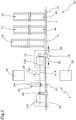
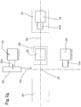
- Figure 1 illustrates a forming drum 13a transported along the intermediate forming line by a first shuttle 14.
- the intermediate forming line 12 comprises a guide 15 which develops preferably rectilinear along a deposition line "L".
- the first shuttle 14, capable of moving, driven by a suitable motor (not illustrated), along the guide 15 and in both directions of movement "S1", "S2" is mounted on the guide 15.
- the first shuttle 14 is capable of supporting a forming drum at a time and rotating it around a rotation axis "X-X" coincident with the longitudinal symmetry axis of the drum itself and with the rotation axis of the tyre 2 being formed.
- the drum is carried cantilevered by the first shuttle 14, which comprises a gripping element capable of withholding or releasing a terminal end of a central shaft of the forming drum.
- a station 16 for dispensing a liner 5 a station 16 for dispensing the first carcass ply 4a, a station 18 for dispensing the second carcass ply 4b are provided by way of example.
- the plant illustrated in figure 1 is thus predisposed for building the tyre 2 illustrated in figure 3 .
- the first shuttle 14 further comprises movement devices, not illustrated, adapted to vertically move the gripping element and the drum constrained thereto in two directions along a direction orthogonal to a longitudinal development of the guide 15. Such movement is aimed at providing carcass structures of different diameters.
- a first transfer location 19 may be defined at one of the terminal ends of the guide 15.
- the intermediate forming line comprises the first transfer location 19.
- the first shuttle 14 is moveable at least up to the first transfer location 19 for making available the forming drum with the intermediate portion of the carcass structure for the subsequent processing operations.
- n completion locations with n ⁇ 1 for completing the intermediate portion of the carcass structure.
- two completion locations for example respectively comprising a tyre bead-forming station 20 and a rolling station 21.
- the plant comprises a second transfer location 22 in which the carcass structure is made available for the subsequent assembling with the crown structure by unloading from the respective forming drum and subsequent transfer to a building drum (not illustrated).
- said crown structure comprises at least one belt strip and a tread band.
- a moveable handling device along a first trajectory 24 is indicated with 23.
- the first shuttle 14 is moveable, in particular between the handling device and the first transfer location 19, following a second trajectory 25.
- the plant 1 also comprises a second shuttle 26.
- the second shuttle 26 is moveable in particular between the handling device 23 and the second transfer location 22 preferably along the second trajectory 25.
- first trajectory 24 and/or the second trajectory 25 are rectilinear.
- first trajectory 24 and the second trajectory 25 are orthogonal to each other as illustrated in the attached figures.
- the second trajectory 25 may be provided by a broken line with a vertex at the handling device.
- the trajectories could be disposed on incident planes.
- a forming drum 13a coming from the intermediate forming line 12 is associated with the first shuttle 14.
- n forming drums are respectively associated with the remaining n completion locations and with the second shuttle 26 leaving one among the n completion locations and the second shuttle 26 free.
- a forming drum 13b is associated to the second shuttle 26 and a forming drum 13c is associated to the rolling station 21 while the tyre bead-forming station 20 is free.
- n forming drums are respectively associated with the remaining n completion locations and the second shuttle.
- the plant 1 may also be operative with only one forming drum for example in the industrialization activities, for example when building small batches of tyres to be controlled step by step.
- the second trajectory 25 intersects the first trajectory 24 at a point 27.
- An exchange location 28 can be observed at or in proximity of such point.
- the n completion locations (tyre bead-forming station 20 and rolling station 21) are fixed.
- the handling device 23 is moveable along the first trajectory 24 between at least one fixed completion location, preferably two fixed completion locations, and the second trajectory 25 as illustrated hereinafter with reference to the operation of the plant 1.
- the first transfer location, the n completion locations and the second transfer location are disposed at the vertices of a polygon.
- the first transfer location 19, two completion locations 20, 21 and the second transfer location 22 are disposed at the vertices of a quadrilateral.
- the first transfer location 19 and the second transfer location 22 are disposed on opposite vertices of the quadrilateral.
- At least one among the first trajectory 24 and the second trajectory 25 crosses the polygon, in particular the quadrilateral.
- the first trajectory 24 and the second trajectory 25 intersect each other inside the polygon or along a side thereof at the exchange location.
- the first trajectory 24 and the second trajectory 25 respectively correspond to one diagonal of the quadrilateral.
- the first transfer location, a completion location and the second transfer location are disposed at the vertices of a triangle.
- the first or second trajectory may coincide with a side of the triangle.
- the aforementioned disposition may for example be provided in the case where the tyre bead-forming station 20 and the rolling station 21 are embedded in a single location.
- the dispensing stations are installed in the intermediate forming line 12.
- the intermediate forming line 12 operates on a forming drum at a time on which the dispensing stations deposit the respective semi-finished products in a predefined sequence.
- the forming of the components of an intermediate portion of a carcass structure of a tyre on the respective forming drum is carried out by making available a forming drum 13a on the first shuttle 14 moveable along the intermediate forming line 12, moving the first shuttle 14 on the intermediate forming line to bring to at least some of a plurality of dispensing stations.
- a component of the intermediate portion of the carcass structure is formed at each of such dispensing stations.
- the first shuttle 14 comprising the forming drum 13a provided with the intermediate portion of the carcass structure, thus reaches the first transfer location 19.
- the intermediate portion of the carcass structure transferring the respective forming drum 13a between the first transfer location 19, the n completion locations, and the second transfer location 22 up to making available the completed carcass structure for the subsequent assembling with the crown structure by transferring the carcass structure itself to a conformation drum (not illustrated) is completed afterwards.
- the forming drum 13a is transferred from the first shuttle 14 to the handling device 23 moveable between the n completion locations bringing the first shuttle 14 at the exchange location 28.
- the handling device transfers the forming drum 13a between the n completion locations for completing the carcass structure.
- the forming drum provided with the completed carcass structure is transferred from the handling device 23 to the second shuttle 26 brought in the exchange position 28.
- the second shuttle 26 is brought in the second transfer location 22 wherein the carcass structure is made available for the subsequent assembling with the crown structure.
- the forming drum 13a clear of the carcass structure is transferred from the second transfer location 22 to the first transfer location 19 for building a subsequent intermediate portion of the carcass structure.
- the forming drum clear of the carcass structure is transferred from the second shuttle 26 to the first shuttle 14, preferably by means of the handling device 23.
- the first shuttle 14 is associated to a forming drum 13a carrying an intermediate portion of the carcass structure disposed along the intermediate forming line 12.
- the forming drum 13a carrying the intermediate portion of the carcass structure associated with the first shuttle 14 is made available at the first transfer location 19 after the first shuttle 14 was moved along the guide 15 at the dispensing stations adapted to obtain the intermediate portion of the carcass structure of the tyre being processed.
- the respective forming drum is transferred between the first transfer location 19, n completion locations with n ⁇ 1, and the second transfer location 22 in which the completed carcass structure is made available for the subsequent assembling with the crown structure by unloading from the respective forming drum.
- the forming drum clear of the carcass structure is transferred from the second transfer location 22 to the first transfer location 19 for building a subsequent intermediate portion of the carcass structure of another tyre.
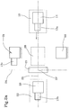
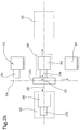
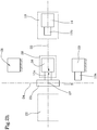
- the forming drum 13a carrying the intermediate portion of the carcass structure disposed along the intermediate forming line 12 is available at the first transfer location 19. Furthermore, the plant provides for further drums, in particular a drum 13b associated to the second shuttle 26 at the second transfer location 22 and a drum 13c associated to one of the completion locations for example to the rolling station 21.
- the first shuttle In order to transfer the forming drum 13a to the tyre bead-forming station 20, the first shuttle is moved along the second trajectory 25 up to the exchange location 28 with the handling device 23.
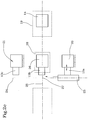
- the forming drum 13a is transferred from the first shuttle 14 to the handling device ( figure 2b ). Following such transfer the handling device 23 is moved along the first trajectory 24 from the exchange location 28 to the free completion location (the bead-forming station 20 in this case). Once the handling device 23 leaves the exchange location 28, the second shuttle 26 provided with the forming drum 13b clear of the carcass structure is moved from the second transfer location 22 to the exchange location 28.
- the handling device 23 reaches the tyre bead-forming station 20 ( figure 2c ) in which the forming drum 13a may be transferred from the handling device 23 to the tyre bead-forming station.
- the handling device 23 is thus moved to return to the exchange location 28, in which the second shuttle 26 is positioned.
- the handling device 23 reaches the exchange location 28.
- the forming drum 13b clear of the carcass structure is transferred from the second shuttle 26 to the handling device 23 ( figure 2d ).
- the handling device 23 with the forming drum 13b is moved away from the exchange location 28.
- the second shuttle 26 moves away from the exchange location 28 (in particular returning to the second transfer location 22 - figure 2e ).
- the handling device 23 with the forming drum 13b is moved towards the exchange location 28 ( figure 2f ).
- the first shuttle 14 is moved towards the exchange location 28.
- the handling device 23 and the first shuttle 14 reach the exchange location 28 in which the forming drum 13b is transferred from the handling device 23 to the first shuttle 14 ( Figure 2f ).
- the first shuttle 14 with the empty forming drum 13b is moved towards the first exchange location 19
- the handling device 23 is moved towards the rolling station 21
- the second shuttle 26 is moved towards the exchange location 28 ( figure 2g ).
- the first shuttle 14 proceeds along the intermediate forming line for the deposition of an intermediate portion of the carcass on the forming drum 13b (step not illustrated).
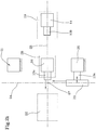
- the handling device 23 reaches the rolling station 21 in which the forming drum 13c is transferred from the rolling station 21 to the handling device 23 ( figure 2g ).
- the second shuttle 26 reaches the exchange location 28.
- the handling device 23 is moved towards the exchange location 28.
- the handling device 23 reaches the exchange location 28 in which it transfers the forming drum 13c to the second shuttle 26 ( figure 2h ).
- the handling device 23 is moved from the exchange location 28 to the tyre bead-forming station 20.
- the handling device 23 reaches the tyre bead-forming station 20 in which the forming drum 13a is transferred to the handling device 23 ( figure 2i ).
- the second shuttle 26 with the forming drum 13c is moved towards the second transfer location 22.
- the handling device 23 with the forming drum 13a is moved towards the rolling station 21.
- the second shuttle 26 with the forming drum 13c reaches the second transfer location 22.
- the handling device 23 with the forming drum 13a reaches the rolling station 21 ( figure 2l ).
- the forming drum 13a is transferred from the handling device to the rolling station 21.
- the handling device 23 and the first shuttle 14 with the forming drum 13b - on which the intermediate portion of the carcass structure is disposed - are moved towards the exchange location 28.
- figure 2l is analogous to that of figure 2a .
- the two conditions differ in that the forming drums have been subjected to a series of transfers.
- the exact configuration of figure 2a occurs after other two cycles analogous to those described previously.
- n locations selected from the n completion locations and the second transfer location are occupied by respective forming drums.
- n forming drums are processed between the remaining n completion locations and the second shuttle 26.
- the transfer of a forming drum between the first transfer location 19, the n completion locations and the second transfer location 22 is carried out by moving the forming drum along at least two trajectories 24, 25 intersecting at a point 27.
- the transfer between the first transfer location 19, the n completion locations and the second transfer location 22 is carried out by moving the handling device 23 along the first trajectory 24 and at least one shuttle between at least one first and second shuttle along the second trajectory 25 intersecting the first trajectory 24.
- the handling device 23 is moved along the first trajectory 24 between the two fixed completion locations, crossing the second trajectory 25.
- At least one first shuttle 14 adapted to carry a forming drum is moved between the first transfer location 19 and the exchange location 28 along the second trajectory 25 intersecting the first trajectory 24.
- At least one second shuttle 26 adapted to carry a forming drum is moved between the exchange location 28 and the second transfer location 22 along the second trajectory 25 intersecting the first trajectory 24.
- the exchange location 28 corresponds to a location at which the forming drum is exchanged between the handling device 23, and the first shuttle 14 or the second shuttle 26.
- the first transfer location 19 is a location disposed along the intermediate forming line 12. Furthermore, the second transfer location 22 is an exchange station interlocked with a station (not illustrated) for assembling the carcass structure with the crown structure.
- the plant described above may be simple, reliable and rigid using moveable handling device/shuttle (besides the movements required for the processing) along a preferably rectilinear and preferably horizontal trajectory.
Landscapes
- Engineering & Computer Science (AREA)
- Mechanical Engineering (AREA)
- Manufacturing & Machinery (AREA)
- Tyre Moulding (AREA)
- Tires In General (AREA)
Claims (15)
- Verfahren zur Steuerung der Fertigung von Reifen für Fahrzeugräder, umfassend:Fertigen einer Karkassenstruktur an einer Formungstrommel (13a-130) ;Montieren der Karkassenstruktur an einer Zenithstruktur;wobei das Fertigen der Karkassenstruktur umfasst:Fertigen eines mittleren Abschnitts der Karkassenstruktur zu einem Zeitpunkt an einer jeweiligen Formungstrommel (13a-13c) in einer Zwischen-Fertigungslinie (12);Verfügbarmachen der Formungstrommel (13a) mit dem mittleren Abschnitt der Karkassenstruktur an einer ersten Übergabestelle (19) ;Fertigstellen des mittleren Abschnitts der Karkassenstruktur durch Übergeben der jeweiligen Formungstrommel (13a) zwischen der ersten Übergabestelle (19), n Fertigstellungsstellen (20, 21) mit n ≥ 1, und einer zweiten Übergabestelle (22).wobei die Karkassenstruktur für die folgende Montage an der Zenithstruktur durch Entladen von der jeweiligen Formungstrommel verfügbar gemacht wird;Übergeben der Formungstrommel (13a) frei von der Karkassenstruktur von der zweiten Übergabestelle (22) an die erste Übergabestelle (19), von wo die Formungstrommel (13a) entlang der Zwischen-Fertigungslinie (12) fortschreitet, um einen folgenden mittleren Abschnitt der Karkassenstruktur zu fertigen;wobei zu einem Betriebszeitpunkt, an dem die erste Übergabestelle (19) von einer Formungstrommel belegt ist, die von der Zwischen-Fertigungslinie kommt, oder für die Zwischen-Fertigungslinie vorgesehen ist, ein bis n Stellen aus den n Fertigstellungsstellen (20, 21) und der zweiten Übergabestelle (22) ausgewählt sind, die von den jeweiligen Formungstrommeln belegt sind.
- Verfahren zur Steuerung der Fertigung von Reifen für Fahrzeugräder nach Anspruch 1, wobei die Übergabe zwischen der ersten Übergabestelle (19), den n Fertigstellungsstellen (20, 21) und der zweiten Übergabestelle (22) durch Bewegen der Formungstrommel entlang zumindest zwei Bahnen (24, 25) ausgeführt wird, die sich an einem Punkt (27) schneiden.
- Verfahren zur Steuerung der Fertigung von Reifen für Fahrzeugräder nach einem oder mehreren der vorhergehenden Ansprüche, wobei die Übergabe zwischen der ersten Übergabestelle (19), n Fertigstellungsstellen (20, 21) und der zweiten Übergabestelle (22) ausgeführt wird, indem eine Manipulationsvorrichtung (23) entlang einer ersten Bahn (24) und zumindest ein Pendeltransporter (14, 26) entlang einer zweiten Bahn (25), welche die erste Bahn (24) schneidet, bewegt wird.
- Verfahren zur Steuerung der Fertigung von Reifen für Fahrzeugräder nach Anspruch 3, wobei zumindest in einer Konfiguration die erste Übergabestelle (19), die n Fertigstellungsstellen (20, 21) und die zweite Übergabestelle (22) an den Scheitelpunkten eines Vielecks angeordnet sind.
- Verfahren zur Steuerung der Fertigung von Reifen für Fahrzeugräder nach Anspruch 4, wobei zumindest eine von erster Bahn (24) und zweiter Bahn (25) das Vieleck schneidet.
- Verfahren zur Steuerung der Fertigung von Reifen für Fahrzeugräder, umfassend:Bilden einer Karkassenstruktur eines Reifens an einer Formungstrommel durch: Verfügbarmachen der Formungstrommel an einem ersten Pendeltransporter (14), der entlang einer Zwischen-Fertigungslinie (12) umfassend eine Führung (15) beweglich ist;Bewegen des ersten Pendeltransporters (14) entlang der Führung (15) in beiden Bewegungsrichtungen (S1, S2) an der Zwischen-Fertigungslinie (12), um ihn zu zumindest einigen einer Vielzahl von Ausgabestationen (16, 17, 18) zu bringen, wobei an jeder der zumindest einigen Ausgabestationen eine Komponente eines mittleren Abschnitts der Karkassenstruktur ausgebildet wird;Bringen des ersten Pendeltransporters (14) umfassend die Formungstrommel, die mit dem mittleren Abschnitt der Karkassenstruktur versehen ist, an eine erste Übergabestelle (19);Übergeben der Formungstrommel von dem ersten Pendeltransporter (14) an eine Manipulationsvorrichtung (23), die zwischen n Fertigstellungsstellen (20, 21) mit n ≥ 1 beweglich ist, wobei der erste Pendeltransporter (14) an eine Austauschstelle (28) mit der ersten Manipulationsvorrichtung (23) gebracht wird;Fertigstellen der Karkassenstruktur durch Übergeben der Formungstrommel zwischen den n Fertigstellungsstellen (20, 21) durch die Manipulationsvorrichtung (23);Übergeben der Formungstrommel, die mit der fertiggestellten Karkassenstruktur versehen ist, an einen zweiten Pendeltransporter (26), der an eine Austauschposition (28) der ersten Manipulationsvorrichtung (23) gebracht wird;Bringen des zweiten Pendeltransporters (26) an eine zweite Übergabestelle (22) zur darauffolgenden Übergabe der Karkassenstruktur, um sie an der Zenithstruktur zu montieren;Übergeben der Formungstrommel frei von der Karkassenstruktur von dem zweiten Pendeltransporter (26) an einen ersten Pendeltransporter (14), von dem der erste Pendeltransporter (14) entlang der Zwischen-Fertigungslinie (12) fortschreitet, um einen darauffolgenden mittleren Abschnitt der Karkassenstruktur zu fertigen;wobei zu einem Betriebszeitpunkt, an dem der erste Pendeltransporter (14) von einer Formungstrommel belegt ist, die von der Zwischen-Fertigungslinie kommt, oder für die Zwischen-Fertigungslinie vorgesehen ist, eine bis n Formungstrommeln (13a-13c) zwischen den verbleibenden n Fertigstellungsstellen (20, 21) und dem zweiten Pendeltransporter (26) bearbeitet werden.
- Verfahren zur Steuerung der Fertigung von Reifen für Fahrzeugräder nach Anspruch 6, wobei zu einem Betriebszeitpunkt, an dem der erste Pendeltransporter (14) von einer Formungstrommel belegt ist, die von der Zwischen-Fertigungslinie kommt, oder für die Zwischen-Fertigungslinie vorgesehen ist, n Formungstrommeln (13a-13c) zwischen den verbleibenden n Fertigstellungsstellen (20, 21) und dem zweiten Pendeltransporter (26) bearbeitet werden, wobei eine unter den n Fertigstellungsstellen (20, 21) und der zweite Pendeltransporter (26) frei bleiben.
- Verfahren zur Steuerung der Fertigung von Reifen für Fahrzeugräder nach Anspruch 6 oder 7, wobei die Manipulationsvorrichtung (23) entlang einer ersten Bahn (24) bewegt wird, und wobei der erste Pendeltransporter (14) und der zweite Pendeltransporter (26) entlang einer zweiten Bahn (25) bewegt werden, welche die erste Bahn (24) schneidet.
- Verfahren zur Steuerung der Fertigung von Reifen für Fahrzeugräder nach Anspruch 8, wobei die Manipulationsvorrichtung (23) entlang der ersten Bahn (24) zwischen zumindest einer feststehenden Fertigstellungsvorrichtung (20, 21) und der zweiten Bahn (25) bewegt wird.
- Verfahren zur Steuerung der Fertigung von Reifen für Fahrzeugräder nach Anspruch 9, wobei die Manipulationsvorrichtung (23) entlang der ersten Bahn (24) zwischen zumindest zwei feststehenden Fertigstellungsvorrichtungen (20, 21) bewegt wird und dabei die zweite Bahn (25) schneidet.
- Verfahren zur Steuerung der Fertigung von Reifen für Fahrzeugräder nach einem oder mehreren der Ansprüche 6 bis 10, wobei die Austauschstelle (28) einer Stelle entspricht, an der die Formungstrommel zwischen der Manipulationsvorrichtung (23) und dem ersten Pendeltransporter (14) oder dem zweiten Pendeltransporter (26) ausgetauscht wird.
- Anlage zur Steuerung der Fertigung von Reifen für Fahrzeugräder, umfassend:eine Fertigungslinie für eine Karkassenstruktur an einer Formungstrommel;eine Station zum Montieren der Karkassenstruktur an einer Zenithstruktur,wobei die Fertigungslinie der Karkassenstruktur umfasst:eine Zwischen-Fertigungslinie (12) zur Herstellung eines mittleren Abschnitts der Karkassenstruktur an einer Formungstrommel, wobei die Zwischen-Fertigungslinie eine erste Übergabestelle (19) umfasst;n Fertigstellungsstellen (20, 21) mit n ≥ 1 zum Fertigstellen des mittleren Abschnitts der Karkassenstruktur, und eine zweite Übergabestelle (22), an der die Karkassenstruktur für die folgende Montage an der Zenithstruktur durch Entladen von der jeweiligen Formungstrommel verfügbar gemacht wird;eine Manipulationsvorrichtung (23), die entlang einer ersten Bahn (24) zwischen den Fertigstellungsstellen (20, 21) beweglich ist;einen ersten Pendeltransporter (14), der entlang einer zweiten Bahn (25) und zwischen einer Austauschstelle (28) mit der Manipulationsvorrichtung (23) und der ersten Übergabestelle (19) beweglich ist, und einem zweiten Pendeltransporter (26), der zwischen der Austauschstelle (28) mit der ersten Manipulationsvorrichtung (23) und der zweiten Übergabestelle (22) entlang der zweiten Bahn (25) beweglich ist,wobei zumindest eine Formungstrommel, die von der Zwischen-Fertigungslinie kommt, oder für die Zwischen-Fertigungslinie vorgesehen ist, dem ersten Pendeltransporter (14) zugeordnet ist, und wobei jeweils eine bis n Formungstrommeln den verbleibenden n Fertigstellungsstellen (20, 21) und dem zweiten Pendeltransporter (26) zugeordnet sind.
- Anlage zur Steuerung der Fertigung von Reifen für Fahrzeugräder nach Anspruch 12, umfassend eine Formungstrommel, die von der Zwischen-Fertigungslinie kommt, oder für die Zwischen-Fertigungslinie vorgesehen ist, und dem ersten Pendeltransporter (14) zugeordnet ist, und n Formungstrommeln, die den verbleibenden n Fertigstellungsstellen (20, 21) und dem zweiten Pendeltransporter (26) zugeordnet sind, wobei eine unter den n Fertigstellungsstellen (20, 21) und der zweite Pendeltransporter (26) frei bleiben.
- Anlage zur Steuerung der Fertigung von Reifen für Fahrzeugräder nach Anspruch 12 oder 13, wobei die zweite Bahn (25) die erste Bahn (24) schneidet.
- Anlage zur Steuerung der Fertigung von Reifen für Fahrzeugräder nach Anspruch 14, wobei die n Fertigstellungsstellen (20, 21) feststehend sind, und wobei die Manipulationsvorrichtung (23) entlang der ersten Bahn (24) zwischen zumindest einer feststehenden Fertigstellungsstelle (20, 21) und der zweiten Bahn (25) beweglich ist.
Applications Claiming Priority (3)
| Application Number | Priority Date | Filing Date | Title |
|---|---|---|---|
| ITMI20112368 | 2011-12-23 | ||
| US201261596477P | 2012-02-08 | 2012-02-08 | |
| PCT/IB2012/057466 WO2013093791A1 (en) | 2011-12-23 | 2012-12-19 | Method, process and plant for controlling the manufacture of tyres for vehicle wheels. |
Publications (2)
| Publication Number | Publication Date |
|---|---|
| EP2794246A1 EP2794246A1 (de) | 2014-10-29 |
| EP2794246B1 true EP2794246B1 (de) | 2018-11-14 |
Family
ID=45614933
Family Applications (1)
| Application Number | Title | Priority Date | Filing Date |
|---|---|---|---|
| EP12823010.9A Active EP2794246B1 (de) | 2011-12-23 | 2012-12-19 | Verfahren und anlage zur steuerung der herstellung von reifen für fahrzeugräder |
Country Status (10)
| Country | Link |
|---|---|
| US (2) | US10363714B2 (de) |
| EP (1) | EP2794246B1 (de) |
| JP (1) | JP6124919B2 (de) |
| KR (1) | KR102060516B1 (de) |
| CN (1) | CN104039539B (de) |
| AR (1) | AR089349A1 (de) |
| BR (1) | BR112014014723B1 (de) |
| MX (2) | MX351493B (de) |
| RU (1) | RU2616689C2 (de) |
| WO (1) | WO2013093791A1 (de) |
Families Citing this family (6)
| Publication number | Priority date | Publication date | Assignee | Title |
|---|---|---|---|---|
| BR112017007854B1 (pt) * | 2014-12-15 | 2021-10-05 | Pirelli Tyre S.P.A. | Método para gerenciar uma linha de construção de estrutura de carcaça, e, processo e instalação para construir estruturas de carcaça de pneu |
| IT201600119949A1 (it) * | 2016-11-28 | 2018-05-28 | Intereuropean Srl | Apparato e metodo per la produzione di pneumatici |
| JP6962096B2 (ja) * | 2017-09-22 | 2021-11-05 | 住友ゴム工業株式会社 | タイヤ形成方法 |
| EP3732031B1 (de) * | 2017-12-28 | 2022-03-30 | Pirelli Tyre S.p.A. | Verfahren und anlage zur herstellung von reifen für fahrzeugräder |
| IT201900012615A1 (it) * | 2019-07-23 | 2021-01-23 | Pirelli | Metodo ed impianto per confezionare pneumatici per ruote di veicoli |
| IT201900023718A1 (it) * | 2019-12-12 | 2021-06-12 | Pirelli | Macchina assemblatrice per il confezionamento di pneumatici per ruote di veicoli, e processo per sostituire tamburi di conformazione in una macchina assemblatrice |
Citations (1)
| Publication number | Priority date | Publication date | Assignee | Title |
|---|---|---|---|---|
| US3318745A (en) * | 1962-12-04 | 1967-05-09 | Us Rubber Co | Method of making a tire carcass |
Family Cites Families (13)
| Publication number | Priority date | Publication date | Assignee | Title |
|---|---|---|---|---|
| GB1214628A (en) * | 1967-03-17 | 1970-12-02 | Dunlop Co Ltd | Improvements in or relating to the manufacture of pneumatic tyres |
| US4268330A (en) * | 1978-12-29 | 1981-05-19 | Bridgestone Tire Company Limited | Green tire building process and apparatus |
| JPS5594647A (en) * | 1979-01-04 | 1980-07-18 | Dow Chemical Co | Improved dehydrogenation reaction catalyst tablet and its preparation |
| IT1254431B (it) | 1992-02-11 | 1995-09-25 | Pirelli | Impianto per il confezionamento di carcasse di pneumatici per ruote di veicoli |
| JPH0811232A (ja) * | 1994-06-29 | 1996-01-16 | Bridgestone Corp | タイヤ成形システム |
| DE19918523C1 (de) | 1999-04-23 | 2000-04-20 | Continental Ag | Reifenaufbauvorrichtung |
| US6746557B2 (en) * | 2001-09-21 | 2004-06-08 | The Goodyear Tire & Rubber Company | Bead loading method and apparatus |
| US6773530B2 (en) * | 2001-09-21 | 2004-08-10 | The Goodyear Tire & Rubber Company | Method for manufacturing tires on a flexible manufacturing system |
| US6793752B2 (en) * | 2001-09-21 | 2004-09-21 | The Goodyear Tire & Rubber Company | Precision longitudinal registration of tire building drum to automated tire building system work station |
| JP4383218B2 (ja) * | 2004-03-29 | 2009-12-16 | 株式会社ブリヂストン | 台車の旋回駆動方法および装置ならびにそれを用いたタイヤ成型システム |
| RU2344933C1 (ru) | 2004-12-16 | 2009-01-27 | Пирелли Тайр С.П.А. | Способ и установка для изготовления шин для колес транспортных средств |
| DE102005055609A1 (de) | 2005-11-22 | 2007-05-24 | Continental Aktiengesellschaft | Transport- und Fertigungssystem zur Verwendung beim Aufbau von Reifenrohlingen |
| US8603275B2 (en) * | 2007-04-23 | 2013-12-10 | Pirelli Tyre S.P.A. | Process and apparatus for manufacturing pneumatic tyres |
-
2012
- 2012-12-19 JP JP2014548299A patent/JP6124919B2/ja active Active
- 2012-12-19 RU RU2014129205A patent/RU2616689C2/ru active
- 2012-12-19 US US14/364,934 patent/US10363714B2/en active Active
- 2012-12-19 KR KR1020147019663A patent/KR102060516B1/ko active Active
- 2012-12-19 CN CN201280066185.5A patent/CN104039539B/zh active Active
- 2012-12-19 WO PCT/IB2012/057466 patent/WO2013093791A1/en not_active Ceased
- 2012-12-19 BR BR112014014723-0A patent/BR112014014723B1/pt active IP Right Grant
- 2012-12-19 MX MX2014006944A patent/MX351493B/es active IP Right Grant
- 2012-12-19 EP EP12823010.9A patent/EP2794246B1/de active Active
- 2012-12-19 MX MX2017002280A patent/MX388274B/es unknown
- 2012-12-20 AR ARP120104848A patent/AR089349A1/es active IP Right Grant
-
2019
- 2019-06-10 US US16/435,747 patent/US11383469B2/en active Active
Patent Citations (1)
| Publication number | Priority date | Publication date | Assignee | Title |
|---|---|---|---|---|
| US3318745A (en) * | 1962-12-04 | 1967-05-09 | Us Rubber Co | Method of making a tire carcass |
Also Published As
| Publication number | Publication date |
|---|---|
| RU2014129205A (ru) | 2016-02-20 |
| JP6124919B2 (ja) | 2017-05-10 |
| MX2014006944A (es) | 2014-08-29 |
| AR089349A1 (es) | 2014-08-13 |
| MX351493B (es) | 2017-10-17 |
| US20140374007A1 (en) | 2014-12-25 |
| EP2794246A1 (de) | 2014-10-29 |
| WO2013093791A1 (en) | 2013-06-27 |
| CN104039539A (zh) | 2014-09-10 |
| JP2015504794A (ja) | 2015-02-16 |
| US11383469B2 (en) | 2022-07-12 |
| BR112014014723A2 (pt) | 2017-06-13 |
| CN104039539B (zh) | 2016-06-08 |
| KR102060516B1 (ko) | 2019-12-30 |
| US10363714B2 (en) | 2019-07-30 |
| US20190344518A1 (en) | 2019-11-14 |
| KR20140107458A (ko) | 2014-09-04 |
| MX388274B (es) | 2025-03-18 |
| BR112014014723B1 (pt) | 2021-02-02 |
| RU2616689C2 (ru) | 2017-04-18 |
Similar Documents
| Publication | Publication Date | Title |
|---|---|---|
| US11383469B2 (en) | Method, process and plant for controlling the manufacture of tyres for vehicle wheels | |
| US11198266B2 (en) | Process and plant for building green tyres for vehicle wheels | |
| US11090890B2 (en) | Process for building tyres for vehicle wheels | |
| EP3352979B1 (de) | Verfahren und anlage zur herstellung von reifen | |
| EP2909018B1 (de) | Verfahren und anlage zur herstellung von fahrzeugreifen | |
| US20170225420A1 (en) | Process and plant for building tyres for vehicle wheels | |
| EP2794249B1 (de) | Verfahren und anlage zur herstellung von reifen für fahrzeugräder | |
| EP3218175A1 (de) | Verfahren zur verwaltung einer karkassenstrukturfertigungslinie, verfahren und anlage zur fertigung von reifenkarkassenstrukturen | |
| EP3240678B1 (de) | Verfahren und vorrichtung zum winden von ringförmigen verankerungsstrukturen in einem reifenherstellungsverfahren. | |
| EP4076925B1 (de) | Verfahren zur herstellung von gürtelanordnungen für reifen für fahrzeugräder | |
| EP4076924B1 (de) | Verfahren und anlage zur herstellung von reifen für fahrzeugräder | |
| US20150306830A1 (en) | Method and plant for building tyres for vehicle wheels | |
| JP5431442B2 (ja) | 車両の車輪用タイヤを製造するための方法及びプラント | |
| JP2015098180A (ja) | 車両の車輪用タイヤを製造するための方法及びプラント | |
| JP2012045950A (ja) | 車両の車輪用タイヤを製造するための方法及びプラント |
Legal Events
| Date | Code | Title | Description |
|---|---|---|---|
| PUAI | Public reference made under article 153(3) epc to a published international application that has entered the european phase |
Free format text: ORIGINAL CODE: 0009012 |
|
| 17P | Request for examination filed |
Effective date: 20140527 |
|
| AK | Designated contracting states |
Kind code of ref document: A1 Designated state(s): AL AT BE BG CH CY CZ DE DK EE ES FI FR GB GR HR HU IE IS IT LI LT LU LV MC MK MT NL NO PL PT RO RS SE SI SK SM TR |
|
| DAX | Request for extension of the european patent (deleted) | ||
| 17Q | First examination report despatched |
Effective date: 20161222 |
|
| GRAP | Despatch of communication of intention to grant a patent |
Free format text: ORIGINAL CODE: EPIDOSNIGR1 |
|
| RIC1 | Information provided on ipc code assigned before grant |
Ipc: B29D 30/24 20060101ALI20180704BHEP Ipc: B29D 30/00 20060101AFI20180704BHEP Ipc: B29D 30/20 20060101ALI20180704BHEP |
|
| INTG | Intention to grant announced |
Effective date: 20180725 |
|
| GRAS | Grant fee paid |
Free format text: ORIGINAL CODE: EPIDOSNIGR3 |
|
| GRAA | (expected) grant |
Free format text: ORIGINAL CODE: 0009210 |
|
| AK | Designated contracting states |
Kind code of ref document: B1 Designated state(s): AL AT BE BG CH CY CZ DE DK EE ES FI FR GB GR HR HU IE IS IT LI LT LU LV MC MK MT NL NO PL PT RO RS SE SI SK SM TR |
|
| REG | Reference to a national code |
Ref country code: CH Ref legal event code: EP Ref country code: AT Ref legal event code: REF Ref document number: 1064301 Country of ref document: AT Kind code of ref document: T Effective date: 20181115 |
|
| REG | Reference to a national code |
Ref country code: IE Ref legal event code: FG4D |
|
| REG | Reference to a national code |
Ref country code: DE Ref legal event code: R096 Ref document number: 602012053577 Country of ref document: DE |
|
| REG | Reference to a national code |
Ref country code: RO Ref legal event code: EPE |
|
| REG | Reference to a national code |
Ref country code: NL Ref legal event code: MP Effective date: 20181114 |
|
| REG | Reference to a national code |
Ref country code: LT Ref legal event code: MG4D |
|
| REG | Reference to a national code |
Ref country code: AT Ref legal event code: MK05 Ref document number: 1064301 Country of ref document: AT Kind code of ref document: T Effective date: 20181114 |
|
| PG25 | Lapsed in a contracting state [announced via postgrant information from national office to epo] |
Ref country code: FI Free format text: LAPSE BECAUSE OF FAILURE TO SUBMIT A TRANSLATION OF THE DESCRIPTION OR TO PAY THE FEE WITHIN THE PRESCRIBED TIME-LIMIT Effective date: 20181114 Ref country code: BG Free format text: LAPSE BECAUSE OF FAILURE TO SUBMIT A TRANSLATION OF THE DESCRIPTION OR TO PAY THE FEE WITHIN THE PRESCRIBED TIME-LIMIT Effective date: 20190214 Ref country code: LV Free format text: LAPSE BECAUSE OF FAILURE TO SUBMIT A TRANSLATION OF THE DESCRIPTION OR TO PAY THE FEE WITHIN THE PRESCRIBED TIME-LIMIT Effective date: 20181114 Ref country code: AT Free format text: LAPSE BECAUSE OF FAILURE TO SUBMIT A TRANSLATION OF THE DESCRIPTION OR TO PAY THE FEE WITHIN THE PRESCRIBED TIME-LIMIT Effective date: 20181114 Ref country code: HR Free format text: LAPSE BECAUSE OF FAILURE TO SUBMIT A TRANSLATION OF THE DESCRIPTION OR TO PAY THE FEE WITHIN THE PRESCRIBED TIME-LIMIT Effective date: 20181114 Ref country code: ES Free format text: LAPSE BECAUSE OF FAILURE TO SUBMIT A TRANSLATION OF THE DESCRIPTION OR TO PAY THE FEE WITHIN THE PRESCRIBED TIME-LIMIT Effective date: 20181114 Ref country code: LT Free format text: LAPSE BECAUSE OF FAILURE TO SUBMIT A TRANSLATION OF THE DESCRIPTION OR TO PAY THE FEE WITHIN THE PRESCRIBED TIME-LIMIT Effective date: 20181114 Ref country code: IS Free format text: LAPSE BECAUSE OF FAILURE TO SUBMIT A TRANSLATION OF THE DESCRIPTION OR TO PAY THE FEE WITHIN THE PRESCRIBED TIME-LIMIT Effective date: 20190314 Ref country code: NO Free format text: LAPSE BECAUSE OF FAILURE TO SUBMIT A TRANSLATION OF THE DESCRIPTION OR TO PAY THE FEE WITHIN THE PRESCRIBED TIME-LIMIT Effective date: 20190214 |
|
| PG25 | Lapsed in a contracting state [announced via postgrant information from national office to epo] |
Ref country code: PT Free format text: LAPSE BECAUSE OF FAILURE TO SUBMIT A TRANSLATION OF THE DESCRIPTION OR TO PAY THE FEE WITHIN THE PRESCRIBED TIME-LIMIT Effective date: 20190314 Ref country code: NL Free format text: LAPSE BECAUSE OF FAILURE TO SUBMIT A TRANSLATION OF THE DESCRIPTION OR TO PAY THE FEE WITHIN THE PRESCRIBED TIME-LIMIT Effective date: 20181114 Ref country code: GR Free format text: LAPSE BECAUSE OF FAILURE TO SUBMIT A TRANSLATION OF THE DESCRIPTION OR TO PAY THE FEE WITHIN THE PRESCRIBED TIME-LIMIT Effective date: 20190215 Ref country code: RS Free format text: LAPSE BECAUSE OF FAILURE TO SUBMIT A TRANSLATION OF THE DESCRIPTION OR TO PAY THE FEE WITHIN THE PRESCRIBED TIME-LIMIT Effective date: 20181114 Ref country code: AL Free format text: LAPSE BECAUSE OF FAILURE TO SUBMIT A TRANSLATION OF THE DESCRIPTION OR TO PAY THE FEE WITHIN THE PRESCRIBED TIME-LIMIT Effective date: 20181114 Ref country code: SE Free format text: LAPSE BECAUSE OF FAILURE TO SUBMIT A TRANSLATION OF THE DESCRIPTION OR TO PAY THE FEE WITHIN THE PRESCRIBED TIME-LIMIT Effective date: 20181114 |
|
| PG25 | Lapsed in a contracting state [announced via postgrant information from national office to epo] |
Ref country code: CZ Free format text: LAPSE BECAUSE OF FAILURE TO SUBMIT A TRANSLATION OF THE DESCRIPTION OR TO PAY THE FEE WITHIN THE PRESCRIBED TIME-LIMIT Effective date: 20181114 Ref country code: PL Free format text: LAPSE BECAUSE OF FAILURE TO SUBMIT A TRANSLATION OF THE DESCRIPTION OR TO PAY THE FEE WITHIN THE PRESCRIBED TIME-LIMIT Effective date: 20181114 Ref country code: DK Free format text: LAPSE BECAUSE OF FAILURE TO SUBMIT A TRANSLATION OF THE DESCRIPTION OR TO PAY THE FEE WITHIN THE PRESCRIBED TIME-LIMIT Effective date: 20181114 |
|
| REG | Reference to a national code |
Ref country code: CH Ref legal event code: PL |
|
| REG | Reference to a national code |
Ref country code: DE Ref legal event code: R097 Ref document number: 602012053577 Country of ref document: DE |
|
| PG25 | Lapsed in a contracting state [announced via postgrant information from national office to epo] |
Ref country code: LU Free format text: LAPSE BECAUSE OF NON-PAYMENT OF DUE FEES Effective date: 20181219 Ref country code: EE Free format text: LAPSE BECAUSE OF FAILURE TO SUBMIT A TRANSLATION OF THE DESCRIPTION OR TO PAY THE FEE WITHIN THE PRESCRIBED TIME-LIMIT Effective date: 20181114 Ref country code: SM Free format text: LAPSE BECAUSE OF FAILURE TO SUBMIT A TRANSLATION OF THE DESCRIPTION OR TO PAY THE FEE WITHIN THE PRESCRIBED TIME-LIMIT Effective date: 20181114 Ref country code: MC Free format text: LAPSE BECAUSE OF FAILURE TO SUBMIT A TRANSLATION OF THE DESCRIPTION OR TO PAY THE FEE WITHIN THE PRESCRIBED TIME-LIMIT Effective date: 20181114 Ref country code: SK Free format text: LAPSE BECAUSE OF FAILURE TO SUBMIT A TRANSLATION OF THE DESCRIPTION OR TO PAY THE FEE WITHIN THE PRESCRIBED TIME-LIMIT Effective date: 20181114 |
|
| REG | Reference to a national code |
Ref country code: IE Ref legal event code: MM4A |
|
| PLBE | No opposition filed within time limit |
Free format text: ORIGINAL CODE: 0009261 |
|
| STAA | Information on the status of an ep patent application or granted ep patent |
Free format text: STATUS: NO OPPOSITION FILED WITHIN TIME LIMIT |
|
| REG | Reference to a national code |
Ref country code: BE Ref legal event code: MM Effective date: 20181231 |
|
| 26N | No opposition filed |
Effective date: 20190815 |
|
| PG25 | Lapsed in a contracting state [announced via postgrant information from national office to epo] |
Ref country code: SI Free format text: LAPSE BECAUSE OF FAILURE TO SUBMIT A TRANSLATION OF THE DESCRIPTION OR TO PAY THE FEE WITHIN THE PRESCRIBED TIME-LIMIT Effective date: 20181114 Ref country code: IE Free format text: LAPSE BECAUSE OF NON-PAYMENT OF DUE FEES Effective date: 20181219 |
|
| PG25 | Lapsed in a contracting state [announced via postgrant information from national office to epo] |
Ref country code: BE Free format text: LAPSE BECAUSE OF NON-PAYMENT OF DUE FEES Effective date: 20181231 |
|
| PG25 | Lapsed in a contracting state [announced via postgrant information from national office to epo] |
Ref country code: LI Free format text: LAPSE BECAUSE OF NON-PAYMENT OF DUE FEES Effective date: 20181231 Ref country code: CH Free format text: LAPSE BECAUSE OF NON-PAYMENT OF DUE FEES Effective date: 20181231 |
|
| PG25 | Lapsed in a contracting state [announced via postgrant information from national office to epo] |
Ref country code: MT Free format text: LAPSE BECAUSE OF NON-PAYMENT OF DUE FEES Effective date: 20181219 |
|
| PG25 | Lapsed in a contracting state [announced via postgrant information from national office to epo] |
Ref country code: TR Free format text: LAPSE BECAUSE OF FAILURE TO SUBMIT A TRANSLATION OF THE DESCRIPTION OR TO PAY THE FEE WITHIN THE PRESCRIBED TIME-LIMIT Effective date: 20181114 |
|
| PG25 | Lapsed in a contracting state [announced via postgrant information from national office to epo] |
Ref country code: CY Free format text: LAPSE BECAUSE OF FAILURE TO SUBMIT A TRANSLATION OF THE DESCRIPTION OR TO PAY THE FEE WITHIN THE PRESCRIBED TIME-LIMIT Effective date: 20181114 Ref country code: MK Free format text: LAPSE BECAUSE OF NON-PAYMENT OF DUE FEES Effective date: 20181114 Ref country code: HU Free format text: LAPSE BECAUSE OF FAILURE TO SUBMIT A TRANSLATION OF THE DESCRIPTION OR TO PAY THE FEE WITHIN THE PRESCRIBED TIME-LIMIT; INVALID AB INITIO Effective date: 20121219 |
|
| PGFP | Annual fee paid to national office [announced via postgrant information from national office to epo] |
Ref country code: DE Payment date: 20241227 Year of fee payment: 13 |
|
| PGFP | Annual fee paid to national office [announced via postgrant information from national office to epo] |
Ref country code: GB Payment date: 20251229 Year of fee payment: 14 |
|
| PGFP | Annual fee paid to national office [announced via postgrant information from national office to epo] |
Ref country code: IT Payment date: 20251219 Year of fee payment: 14 |
|
| PGFP | Annual fee paid to national office [announced via postgrant information from national office to epo] |
Ref country code: FR Payment date: 20251226 Year of fee payment: 14 |
|
| PGFP | Annual fee paid to national office [announced via postgrant information from national office to epo] |
Ref country code: RO Payment date: 20251205 Year of fee payment: 14 |