EP2794110B1 - Granulator - Google Patents
Granulator Download PDFInfo
- Publication number
- EP2794110B1 EP2794110B1 EP12815637.9A EP12815637A EP2794110B1 EP 2794110 B1 EP2794110 B1 EP 2794110B1 EP 12815637 A EP12815637 A EP 12815637A EP 2794110 B1 EP2794110 B1 EP 2794110B1
- Authority
- EP
- European Patent Office
- Prior art keywords
- granulator
- module housing
- housing
- cutting device
- drive
- Prior art date
- Legal status (The legal status is an assumption and is not a legal conclusion. Google has not performed a legal analysis and makes no representation as to the accuracy of the status listed.)
- Active
Links
Images


Classifications
-
- B—PERFORMING OPERATIONS; TRANSPORTING
- B02—CRUSHING, PULVERISING, OR DISINTEGRATING; PREPARATORY TREATMENT OF GRAIN FOR MILLING
- B02C—CRUSHING, PULVERISING, OR DISINTEGRATING IN GENERAL; MILLING GRAIN
- B02C18/00—Disintegrating by knives or other cutting or tearing members which chop material into fragments
- B02C18/06—Disintegrating by knives or other cutting or tearing members which chop material into fragments with rotating knives
- B02C18/14—Disintegrating by knives or other cutting or tearing members which chop material into fragments with rotating knives within horizontal containers
- B02C18/148—Disintegrating by knives or other cutting or tearing members which chop material into fragments with rotating knives within horizontal containers specially adapted for disintegrating plastics, e.g. cinematographic films
-
- B—PERFORMING OPERATIONS; TRANSPORTING
- B02—CRUSHING, PULVERISING, OR DISINTEGRATING; PREPARATORY TREATMENT OF GRAIN FOR MILLING
- B02C—CRUSHING, PULVERISING, OR DISINTEGRATING IN GENERAL; MILLING GRAIN
- B02C18/00—Disintegrating by knives or other cutting or tearing members which chop material into fragments
- B02C18/06—Disintegrating by knives or other cutting or tearing members which chop material into fragments with rotating knives
- B02C18/16—Details
-
- B—PERFORMING OPERATIONS; TRANSPORTING
- B29—WORKING OF PLASTICS; WORKING OF SUBSTANCES IN A PLASTIC STATE IN GENERAL
- B29B—PREPARATION OR PRETREATMENT OF THE MATERIAL TO BE SHAPED; MAKING GRANULES OR PREFORMS; RECOVERY OF PLASTICS OR OTHER CONSTITUENTS OF WASTE MATERIAL CONTAINING PLASTICS
- B29B9/00—Making granules
- B29B9/02—Making granules by dividing preformed material
- B29B9/06—Making granules by dividing preformed material in the form of filamentary material, e.g. combined with extrusion
-
- B—PERFORMING OPERATIONS; TRANSPORTING
- B02—CRUSHING, PULVERISING, OR DISINTEGRATING; PREPARATORY TREATMENT OF GRAIN FOR MILLING
- B02C—CRUSHING, PULVERISING, OR DISINTEGRATING IN GENERAL; MILLING GRAIN
- B02C18/00—Disintegrating by knives or other cutting or tearing members which chop material into fragments
- B02C18/06—Disintegrating by knives or other cutting or tearing members which chop material into fragments with rotating knives
- B02C18/16—Details
- B02C2018/162—Shape or inner surface of shredder-housings
-
- B—PERFORMING OPERATIONS; TRANSPORTING
- B02—CRUSHING, PULVERISING, OR DISINTEGRATING; PREPARATORY TREATMENT OF GRAIN FOR MILLING
- B02C—CRUSHING, PULVERISING, OR DISINTEGRATING IN GENERAL; MILLING GRAIN
- B02C18/00—Disintegrating by knives or other cutting or tearing members which chop material into fragments
- B02C18/06—Disintegrating by knives or other cutting or tearing members which chop material into fragments with rotating knives
- B02C18/16—Details
- B02C18/22—Feed or discharge means
- B02C2018/2208—Feed or discharge means for weblike material
Definitions
- the invention relates to a granulator having a driven by a drive device cutting device, wherein the drive device is accommodated in a pelletizer housing and the cutting device is accommodated in a module housing, which is connected in a detachable manner with the pelletizer housing and is removable from this, and wherein the cutting device via a detachable Coupling is connected to the drive device.
- a granulator is used to cut a strand of material, which may for example consist of extruded plastic, into small parts, since the material can be better transported and stored in this way.
- the material strand can be a so-called endless strand if the strand issuing directly from an extruder is fed to the granulator.
- the term "material strand” should also be understood to mean strand-like sections of an endless strand of material and rod-shaped pieces of material.
- the material strand is cut into small pieces at its front end by means of the cutting device, which may be a rotating or an alternately reciprocating knife, usually directly downwards into a receptacle fall and be collected in this.
- the cutting device is connected via a drive shaft with a drive device which sits in the Granluatorgeophuse.
- the material strand In order to obtain granules of desired size, the material strand must be fed at a defined speed of the cutting device.
- a conveyor device is usually provided in the granulator, which has a rotationally driven drive wheel and a pressure roller, between which a strand of material is passed.
- the drive wheel is connected via a shaft with a drive device in connection, which is also disposed within the granulator housing.
- a granulator which has a driven by a drive device cutting device in the form of a rotating cutter wheel, wherein the drive device is accommodated in a granulator housing.
- a box-like bearing plate is provided which receives the cutter wheel, which is arranged between the bearing plate and the granulator housing.
- a cover can be placed on the side facing away from the knife wheel.
- a granulator is also used in production areas in which very high hygienic requirements prevail, for example in the production of food or pharmaceuticals. If a product change is to be made on a granulator, ie if instead of a material strand of a first material now a material strand of another second material is to be processed, it must be ensured that in the granulator no remains of the previously processed first material which could contaminate the granules of the second material. It is known for this purpose that the granulator must first be completely cleaned when changing the product.
- the invention has for its object to provide a granulator of the type mentioned, in which a product change can be achieved quickly and easily, without the risk of contamination of the environment consists of cutting residues.
- the invention is based on the basic idea of designing the cutting device as an independent module-like structural unit, which has a separate module housing, which can be attached to the granulator housing, wherein the cutting device is connected to its drive device via the coupling.
- the module housing is degraded together with the cutting device, which is received in the module housing and forms a unit with this, from the granulator housing under release of the clutch and can then be cleaned.
- a new module housing of the same construction, i. including a cutting device are mounted to the granulator housing, wherein the cutting device is connected via the coupling with its drive device.
- the granulator may continue to operate while cleaning the previously used and disassembled module housing with the cutter. In this way, the downtime of the granulator can be kept very short.
- the conveying device in addition to the cutting device also driven by a drive device conveying device is provided, with which the material strand to be cut can be fed to the cutting device, wherein the conveyor also accommodated in the module housing and degraded together with this as a unit of the granulator housing can be.
- the conveying device via a releasable coupling connected to its drive device.
- a common drive device may be provided, but preferably the cutting device and the conveying device each have their own drive device.
- the conveying device has a rotationally driven drive wheel and a pressure roller, between which the material strand can be transported.
- the pressure roller is tensioned under spring load against the drive wheel, so that a good transmission of the driving force is ensured on the material strand.
- the spring load of the pressure roller can be adjusted and thereby adaptable to different materials.
- the drive wheel has on its peripheral surface structuring, for example, a knurling.
- the cutting device and / or the conveying device are accommodated in an interior of the module housing, which can be closed by means of a cover.
- the cover can be, for example, a door or flap which, in particular, can be made transparent at least in sections so that a user can observe and monitor the operation and the proper functioning of the conveyor device and the cutting device.
- each clutch can be used, which ensures a good power transmission from the drive device to the cutting device or conveying device and also can be solved in a simple manner.
- a plug-in coupling is used.
- the releasable coupling of the conveying device thus has at least one and preferably at least two engagement pins, which can each be inserted into a corresponding receptacle, preferably with a close fit. By means of the engagement pin or the engagement pins, a torque can be transmitted in a simple manner.
- the releasable coupling of the cutting device may comprise at least one and preferably at least two engagement pins, which can each be inserted into a corresponding receptacle.
- At least one of the couplings has a centering pin which can be inserted into a centering receptacle ,
- a granulator 10 shown in the figures has a pelletizer housing 13 and a module housing 20 which can be attached to it and can be dismantled by it.
- a cutting device 11 is arranged in the module housing 20, in which a cutting device 11 is arranged.
- the cutting device 11 comprises a cutting wheel 23 which has a plurality of circumferentially spaced cutting teeth 24.
- the cutting wheel 23 is seated on a shaft 35 which is rotatable about an axis A.
- a conveyor device 12 is arranged in the module housing 20.
- the conveying device 12 comprises a drive wheel 26 which has a structuring 30 in the form of a knurl on its peripheral surface and is seated on a shaft 36 which is rotatably mounted about an axis B.
- the axes A and B are parallel to each other.
- the conveying device 12 comprises a rotatably mounted pressure roller 25, which is tensioned by means of a spring force indicated only schematically by an arrow F against the drive wheel 26.
- FIG. 2 shows, a strand of material S between the drive wheel 26 and the pressure roller 25 is inserted and clamped between these two components.
- the drive wheel 26 is rotated, the material strand S is thereby conveyed in its longitudinal direction and fed to the cutting device 11, which cuts off a piece of material strand S at the front end of the material strand S and thus granulates it.
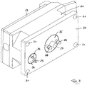
- the interior 34 of the module housing 20 can be closed by means of a door or flap-like cover 22, which is transparent in the illustrated embodiment.
- this On the side facing away from the cover 22 back of the module housing 20, this has a back plate 37 which is provided in their corner areas with holes 21, in the correspondingly arranged, attached to the granulator housing 13 retaining pins 18 can be inserted.
- the shaft 35 of the cutting device 11 penetrates the back plate 37 and ends at the back substantially flush therewith.
- a central centering pin 27 and two laterally offset thereto drive pins 28 are formed, which protrude in the axial direction of the shaft 35.
- the shaft 36 of the conveyor 12 duchdringt the back plate 37 and ends at the back substantially flush with this.
- On the shaft 36 two in the axial direction of the shaft 36 rearwardly projecting drive pins 29 are formed.
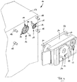
- FIG. 4 is in the granulator housing 13, a drive device 14 for the cutting device 11 is arranged, wherein of the drive device 14, only the end of a drive shaft 38 is shown, which has on its outer face a central Zentrier matter 33 and a plurality of distributed over the circumference arranged hole-like receptacles 32.
- the drive shaft 38 in cooperation with the centering pin 27 and the drive pins 28 of the shaft 35 of the cutting device 11 forms a releasable coupling 16 with which a torque can be transmitted.
- a drive device 15 is arranged for the conveyor 12, of which only the front end of a drive shaft 39 can be seen, at the frontal end a plurality of distributed over the circumference arranged hole-shaped receptacles 31 are formed in cooperation with the Drive pins 29 of the shaft 36 of the conveyor 12 form a releasable coupling 17 with which a torque can be transmitted.
- the module housing 20 For mounting the module housing 20, this is placed with its back plate 37 on the retaining pins 18 of the pelletizer housing 13, that the retaining pins 18 pass through the holes 21 of the back plate 37 of the module housing 20. At the same time the centering pin 27 of the shaft 35 is inserted into the centering 33 of the drive shaft 38 and the Drive pins 28 of the shaft 35 are inserted into two diametrically opposed receptacles 32 of the drive shaft 38. Thus, the drive shaft 38 is connected to the shaft 35 of the cutting device 11 in operative connection, so that a torque can be transmitted.
- the nuts 19 are released and the module housing 20 is removed together with all arranged in the module housing 20 add-on parts, in particular the cutting device 11 and the conveyor 12 as a unit of the retaining pins 18.
- the coupling 16 between the drive device 14 and the cutting device 11 and the coupling 17 between the drive device 15 and the conveyor 12 are solved. This condition is in FIG. 4 shown.
- the previously used module housing can then be brought to an external cleaning station, while at the same time a new module housing is attached to the granulator housing in the manner mentioned, so that a different material strand can be processed.
Landscapes
- Engineering & Computer Science (AREA)
- Food Science & Technology (AREA)
- Mechanical Engineering (AREA)
- Processing And Handling Of Plastics And Other Materials For Molding In General (AREA)
- Crushing And Pulverization Processes (AREA)
- Glanulating (AREA)
- Screw Conveyors (AREA)
Description
- Die Erfindung betrifft einen Granulator mit einer von einer Antriebsvorrichtung angetriebenen Schneidvorrichtung, wobei die Antriebsvorrichtung in einem Granulatorgehäuse aufgenommen und die Schneidvorrichtung in einem Modulgehäuse aufgenommen ist, das in lösbarer Weise mit dem Granulatorgehäuse verbunden und von diesem abnehmbar ist, und wobei die Schneidvorrichtung über eine lösbare Kupplung mit der Antriebsvorrichtung verbunden ist.
- Eine derartige Vorrichtung ist aus der
US 5 996 457 A bekannt. - Ein Granulator dient dazu, einen Materialstrang, der beispielsweise aus extrudiertem Kunststoff bestehen kann, in kleine Teile zu zerschneiden, da das Material auf diese Weise besser transportiert und gelagert werden kann. Bei dem Materialstrang kann es sich um einen sogenannten endlosen Strang handeln, wenn der direkt aus einem Extruder austretende Strang dem Granulator zugeführt wird. Unter dem Begriff "Materialstrang" sollen jedoch auch strangähnliche Abschnitte eines endlosen Materialstrangs sowie stangenförmige Materialstücke verstanden werden.
- In dem Granulator wird der Materialstrang an seinem vorderen Ende mittels der Schneidvorrichtung, bei der es sich um ein rotierendes oder um ein alternierend hin und her bewegbares Messer handeln kann, in kleine Stücke geschnitten, die üblicherweise direkt nach unten in einen Aufnahmebehälter fallen und in diesem gesammelt werden. Die Schneidvorrichtung ist über eine Antriebswelle mit einer Antriebsvorrichtung verbunden, die in dem Granluatorgehäuse sitzt.
- Um ein Granulat gewünschter Größe zu erhalten, muss der Materialstrang mit definierter Geschwindigkeit der Schneidvorrichtung zugeführt werden. Zu diesem Zweck ist üblicherweise in dem Granulator eine Fördervorrichtung vorgesehen, die ein drehangetriebenes Antriebsrad und eine Druckrolle aufweist, zwischen denen ein Materialstrang hindurchgeführt ist. Das Antriebsrad steht über eine Welle mit einer Antriebsvorrichtung in Verbindung, die ebenfalls innerhalb des Granulatorgehäuses angeordnet ist.
- Aus der
US 7,270,285 B2 ist ein Granulator bekannt, der eine von einer Antriebsvorrichtung angetriebene Schneidvorrichtung in Form eines rotierenden Messerrades aufweist, wobei die Antriebsvorrichtung in einem Granulatorgehäuse aufgenommen ist. Zusätzlich ist eine gehäuseartige Lagerplatte vorgesehen, die das Messerrad aufnimmt, das zwischen der Lagerplatte und dem Granulatorgehäuse angeordnet ist. Auf die Lagerplatte ist auf der dem Messerrad abgewandten Seite eine Abdeckung aufsetzbar. - Ein Granulator findet auch in Produktionsbereichen Anwendung, in denen sehr hohe hygienische Anforderungen herrschen, beispielsweise bei der Herstellung von Lebensmitteln oder Arzneimitteln. Wenn an einem Granulator ein Produktwechsel vorgenommen werden soll, d.h. wenn statt eines Materialstrangs aus einem ersten Material nun ein Materialstrang aus einem anderen zweiten Material verarbeitet werden soll, muss sichergestellt sein, dass sich in dem Granulator keine Reste des bisher verarbeiteten ersten Materials befinden, die das Granulat des zweiten Materials verunreinigen könnten. Es ist zu diesem Zweck bekannt, dass der Granulator bei einem Produktwechsel zunächst vollständig gereinigt werden muss. Wenn an die Verarbeitung der jeweiligen Materialien sehr hohe hygienische Anforderungen gestellt werden, ist es notwendig, die Schneidvorrichtung und die Fördervorrichtung vollständig auseinander zu bauen, abseits des bisherigen Einsatzortes zu reinigen und anschließend am Einsatzort wieder zusammen zu bauen. Dies führt zu sehr langen Stillstandszeiten des Granulators, was sehr unwirtschaftlich ist.
- Um die Schneidvorrichtung gemäß der
US 7,270,285 B2 zum Zwecke der Reinigung auseinander zu bauen, muss zunächst die Abdeckung abgenommen werden. Anschließend werden eine zentrale Motorwelle und Befestigungsschrauben gelöst, so dass die Lagerplatte, das Messerrad und das Granulatorgehäuse voneinander frei kommen. Dabei sind die Lagerplatte und das Messerrad jeweils lose, so dass die Gefahr besteht, dass diese Teile herunterfallen und die Umgebung mit Schneidrückständen verschmutzen. Darüber hinaus können an der Lageplatte oder dem Messerrad sitzende Schneidrückstände herunterfallen, was ebenfalls zu einer Verunreinigung der Umgebung führt. Desweiteren ist der Montageaufwand für den Auseinanderbau und anschließenden Zusammenbau relativ groß und somit kostenintensiv. - Der Erfindung liegt die Aufgabe zugrunde, einen Granulator der genannten Art zu schaffen, bei dem sich ein Produktwechsel schnell und in einfacher Weise erreichen lässt, ohne dass die Gefahr der Verunreinigung der Umgebung mit Schneidrückständen besteht.
- Diese Aufgabe wird erfindungsgemäß durch einen Granulator mit den Merkmalen des Anspruchs 1 gelöst. Dabei ist vorgesehen, dass die Schneidvorrichtung zusammen mit dem Modulgehäuse als Einheit von dem Granulatorgehäuse abnehmbar ist.
- Die Erfindung geht von dem Grundgedanken aus, die Schneidvorrichtung als eigenständige modulartige Baueinheit auszubilden, die ein separates Modulgehäuse aufweist, das an das Granulatorgehäuse anbaubar ist, wobei die Schneidvorrichtung mit ihrer Antriebsvorrichtung über die Kupplung verbunden wird. Bei einem Produktwechsel wird das Modulgehäuse zusammen mit der Schneidvorrichtung, die in dem Modulgehäuse aufgenommen ist und mit diesem eine Einheit bildet, von dem Granulatorgehäuse unter Lösen der Kupplung abgebaut und kann dann gereinigt werden. Gleichzeitig kann ein neues Modulgehäuse gleichen Aufbaus, d.h. einschließlich einer Schneidvorrichtung an das Granulatorgehäuse angebaut werden, wobei die Schneidvorrichtung über die Kupplung mit ihrer Antriebsvorrichtung verbunden wird. Somit kann der Granulator weiterhin in Betrieb bleiben, während das vorher benutzte und abgebaute Modulgehäuse mit der Schneidvorrichtung gereinigt wird. Auf diese Weise können die Stillstandszeiten des Granulators sehr kurz gehalten werden.
- Gemäß der Erfindung ist vorgesehen, dass neben der Schneidvorrichtung auch eine von einer Antriebsvorrichtung angetriebene Fördervorrichtung vorgesehen ist, mit der der zu schneidende Materialstrang der Schneidvorrichtung zugeführt werden kann, wobei die Fördervorrichtung ebenfalls in dem Modulgehäuse aufgenommen und zusammen mit diesem als Einheit von dem Granulatorgehäuse abgebaut werden kann. Vorzugsweise ist die Fördervorrichtung über eine lösbare Kupplung mit ihrer Antriebsvorrichtung verbunden.
- Für die Schneidvorrichtung und die Fördervorrichtung kann eine gemeinsame Antriebsvorrichtung vorgesehen sein, vorzugsweise besitzen die Schneidvorrichtung und die Fördervorrichtung jedoch jeweils eine eigene Antriebsvorrichtung.
- In bevorzugter Ausgestaltung der Erfindung ist vorgesehen, dass alle mit dem Materialstrang in Kontakt kommenden Bauteile in oder an dem Modulgehäuse sind. Auf diese Weise ist sichergestellt, dass eventuelle Produktreste des verarbeiteten Produktes sich nur in oder an dem Modulgehäuse befinden können und zuverlässig entfernt werden, wenn das Modulgehäuse abgebaut wird.
- In einer möglichen Ausgestaltung der Erfindung ist vorgesehen, dass die Fördervorrichtung ein drehangetriebenes Antriebsrad und eine Druckrolle aufweist, zwischen denen der Materialstrang transportierbar ist. Vorzugsweise ist die Druckrolle unter Federbelastung gegen das Antriebsrad gespannt, so dass eine gute Übertragung der Antriebskraft auf den Materialstrang gewährleistet ist. Dabei kann die Federbelastung der Druckrolle einstellbar und dadurch an unterschiedliche Materialien anpassbar sein.
- Um eine gute Kraftübertragung zwischen der Umfangsfläche des Antriebsrades und dem Materialstrang zu gewährleisten, kann in Weiterbildung der Erfindung vorgesehen sein, dass das Antriebsrad an seiner Umfangsfläche eine Strukturierung, beispielsweise eine Rändelung aufweist.
- Bei der Schneidvorrichtung kann es sich um ein drehangetriebenes Schneidrad beispielsweise mit einer senkrecht zur Längsachse des Materialstrangs verlaufenden Drehachse handeln, wobei das Schneidrad mehrere über den Umfang verteilte Schneidzähne aufweisen kann. Es ist jedoch auch möglich, dass die Schneidvorrichtung von einem linear hin und her bewegten Messer gebildet ist, das vorzugsweise vertikal oberhalb oder unterhalb des zu schneidenden Endes des Materialstrangs angeordnet ist.
- Um zu vermeiden, dass Produktreste bei dem Schneiden des Materialstrangs an die Umgebung gelangen, kann in bevorzugter Ausgestaltung der Erfindung vorgesehen sein, dass die Schneidvorrichtung und/oder die Fördervorrichtung in einem Innenraum des Modulgehäuses aufgenommen sind, der mittels einer Abdeckung verschließbar ist. Bei der Abdeckung kann es sich beispielsweise um eine Tür oder Klappe handeln, die insbesondere zumindest abschnittsweise transparent ausgestaltet sein kann, damit ein Benutzer den Betrieb und die ordnungsgemäße Funktion der Fördervorrichtung und der Schneidvorrichtung betrachten und überwachen kann.
- In Weiterbildung der Erfindung kann vorgesehen sein, dass die Abdeckung bzw. die von der Abdeckung abgedeckte Öffnung des Modulgehäuses auf der den Kupplungen abgewandten Seite des Modulgehäuses und somit auch dem Granulatorgehäuse abgewandt angeordnet ist. Die Fördervorrichtung und die Schneidvorrichtung sind in dem Modulgehäuse weitestgehend gekapselt und von der Umgebung abgeschlossen. Lediglich für den Einlass des Materialstrangs ist ein Durchlass geringer Größe vorgesehen und gegebenenfalls kann eine Auslassöffnung für die abgeschnittenen Teilchen, d.h. das Granulat, ausgebildet sein. Falls es notwendig sein sollte, die Abdeckung zu öffnen, ist durch deren von dem Granulatorgehäuse abgewandte Ausrichtung sichergestellt, dass eine Verschmutzung des Granulatorgehäuses und/oder der Kupplungen mit Produktresten sehr unwahrscheinlich ist.
- Als Kupplung zwischen der Schneidvorrichtung bzw. der Fördervorrichtung und der jeweiligen Antriebsvorrichtung kann jede Kupplung verwendet werden, die eine gute Kraftübertragung von der Antriebsvorrichtung auf die Schneidvorrichtung bzw. Fördervorrichtung gewährleistet und sich darüber hinaus in einfacher Weise lösen lässt. In bevorzugter Ausgestaltung der Erfindung ist eine Steckkupplung verwendet. Die lösbare Kupplung der Fördervorrichtung weist somit zumindest einen und vorzugsweise zumindest zwei Eingriffsstifte auf, die jeweils in eine entsprechende Aufnahme unter vorzugsweise enger Passung eingesetzt werden können. Mittels des Eingriffsstifts bzw. der Eingriffsstifte lässt sich ein Drehmoment in einfacher Weise übertragen.
- Auch die lösbare Kupplung der Schneidvorrichtung kann zumindest einen und vorzugsweise zumindest zwei Eingriffsstifte aufweisen, die jeweils in eine entsprechende Aufnahme eingeführt werden können.
- Um eine exakte Positionierung des Modulgehäuses relativ zu dem Granulatorgehäuse und dadurch auch ein leichtes und exaktes Einführen der Eingriffsstifte in die jeweilige Aufnahme zu erleichtern, kann in Weiterbildung der Erfindung vorgesehen sein, dass zumindest eine der Kupplungen einen Zentrierstift aufweist, der in eine Zentrieraufnahme einführbar ist.
- Weitere Einzelheiten und Merkmale der Erfindung sind aus der folgenden Beschreibung eines Ausführungsbeispiels unter Bezugnahme auf die Zeichnung ersichtlich. Es zeigen:
- Fig. 1
- Eine ausschnittsweise perspektivische Darstellung eines Granulators mit montiertem Modulgehäuse,
- Fig. 2
- eine Vorderansicht des Modulgehäuses,
- Fig. 3
- eine perspektivische Rückansicht des Modulgehäuses und
- Fig. 4
- eine
Figur 1 entsprechende Darstellung mit abgenommenem Modulgehäuse. - Ein in den Figuren dargestellter Granulator 10 besitzt ein Granulatorgehäuse 13 und ein daran anbaubares sowie von diesem abbaubares Modulgehäuse 20. In dem Modulgehäuse 20 ist ein Innenraum 34 ausgebildet, in dem eine Schneidvorrichtung 11 angeordnet ist. Die Schneidvorrichtung 11 umfasst ein Schneidrad 23, das mehrere über den Umfang verteilt angeordnete Schneidzähne 24 besitzt. Das Schneidrad 23 sitzt auf einer Welle 35, die um eine Achse A drehbar ist.
- Darüber hinaus ist in dem Modulgehäuse 20 eine Fördervorrichtung 12 angeordnet. Die Fördervorrichtung 12 umfasst ein Antriebsrad 26, das auf seiner Umfangsfläche eine Strukturierung 30 in Form einer Rändelung besitzt und auf einer Welle 36 sitzt, die um eine Achse B drehbar gelagert ist. Im dargestellten Ausführungsbeispiel verlaufen die Achsen A und B parallel zueinander.
- Ferner umfasst die Fördervorrichtung 12 eine drehbar gelagerte Druckrolle 25, die mittels einer nur schematisch durch einen Pfeil F angedeutete Federkraft gegen das Antriebsrad 26 gespannt ist.
- Wie
Figur 2 zeigt, kann ein Materialstrang S zwischen das Antriebsrad 26 und die Druckrolle 25 eingeführt und zwischen diesen beiden Bauteilen eingespannt werden. Wenn das Antriebsrad 26 gedreht wird, wird dadurch der Materialstrang S in seine Längsrichtung gefördert und der Schneidvorrichtung 11 zugeführt, die am vorderen Ende des Materialstrangs S ein Stück vom Materialstrang S abschneidet und so diesen granuliert. - Der Innenraum 34 des Modulgehäuses 20 ist mittels einer Tür oder klappenartigen Abdeckung 22 verschließbar, die im dargestellten Ausführungsbeispiel transparent ist.
- Auf der der Abdeckung 22 abgewandten Rückseite des Modulgehäuses 20 besitzt dieses eine Rückplatte 37, die in ihren Eckbereichen mit Bohrungen 21 versehen ist, in die entsprechend angeordnete, am Granulatorgehäuse 13 befestigte Haltestifte 18 eingeführt werden können.
- Wie
Figur 3 zeigt, durchdringt die Welle 35 der Schneidvorrichtung 11 die Rückplatte 37 und endet auf der Rückseite im wesentlichen bündig mit dieser. An dem rückwertigen Ende der Welle 35 sind ein zentraler Zentrierstift 27 und zwei seitlich dazu versetzte Antriebsstifte 28 ausgebildet, die in Axialrichtung der Welle 35 hervorstehen. - Auch die Welle 36 der Fördervorrichtung 12 duchdringt die Rückplatte 37 und endet rückseitig im wesentlichen bündig mit dieser. An der Welle 36 sind zwei in Axialrichtung der Welle 36 nach hinten hervorstehende Antriebsstifte 29 angeformt.
- Gemäß
Figur 4 ist in dem Granulatorgehäuse 13 eine Antriebsvorrichtung 14 für die Schneidvorrichtung 11 angeordnet, wobei von der Antriebsvorrichtung 14 nur das Ende einer Antriebswelle 38 dargestellt ist, die auf ihrer äußeren Stirnseite eine zentrale Zentrieraufnahme 33 sowie mehrere über den Umfang verteilt angeordnete lochartige Aufnahmen 32 besitzt. Die Antriebswelle 38 bildet im Zusammenwirken mit dem Zentrierstift 27 und den Antriebsstiften 28 der Welle 35 der Schneidvorrichtung 11 eine lösbare Kupplung 16, mit der ein Drehmoment übertragen werden kann. - Darüber hinaus ist in dem Granulatorgehäuse 13 eine Antriebsvorrichtung 15 für die Fördervorrichtung 12 angeordnet, von der nur das stirnseitige Ende einer Antriebswelle 39 zu sehen ist, an deren stirnseitigem Ende mehrere über den Umfang verteilt angeordnete lochförmige Aufnahmen 31 ausgebildet sind, die im Zusammenwirken mit den Antriebsstiften 29 der Welle 36 der Fördervorrichtung 12 eine lösbare Kupplung 17 bilden, mit der ein Drehmoment übertragen werden kann.
- Zur Montage des Modulgehäuses 20 wird dieses mit seiner Rückplatte 37 so auf die Haltestifte 18 des Granulatorgehäuses 13 aufgesetzt, dass die Haltestifte 18 die Bohrungen 21 der Rückplatte 37 des Modulgehäuses 20 durchgreifen. Gleichzeitig wird der Zentrierstift 27 der Welle 35 in die Zentrieraufnahme 33 der Antriebswelle 38 eingeführt und die Antriebsstifte 28 der Welle 35 werden in zwei diametral gegenüberliegende Aufnahmen 32 der Antriebswelle 38 eingesetzt. Damit steht die Antriebswelle 38 mit der Welle 35 der Schneidvorrichtung 11 in Wirkverbindung, so dass ein Drehmoment übertragen werden kann.
- Gleichzeitig werden die Antriebsstifte 29 der Welle 36 der Fördervorrichtung 12 in zwei diametral gegenüberliegende Aufnahmen 31 der Antriebswelle 39 eingeführt, so dass auch die Kupplung 17 zwischen der Antriebswelle 39 und der Welle 36 der Fördervorrichtung 12 zur Übertragung eines Drehmomentes gekuppelt ist. Wenn das Modulgehäuse 20 auf dem Granulatorgehäuse 13 korrekt positioniert ist, werden auf die hervorstehenden Haltestifte 18 Muttern 19 aufgeschraubt, um das Modulgehäuse 20 zu fixieren.
- Zum Austausch bzw. Abbau des Modulgehäuses 20 werden die Muttern 19 gelöst und das Modulgehäuse 20 wird zusammen mit allen im Modulgehäuse 20 angeordneten Anbauteilen, insbesondere der Schneidvorrichtung 11 und der Fördervorrichtung 12 als Einheit von den Haltestiften 18 abgenommen. Dabei werden auch die Kupplung 16 zwischen der Antriebsvorrichtung 14 und der Schneidvorrichtung 11 sowie die Kupplung 17 zwischen der Antriebsvorrichtung 15 und der Fördervorrichtung 12 gelöst. Dieser Zustand ist in
Figur 4 dargestellt. Das bisher benutzte Modulgehäuse kann dann zu einem externen Reinigungsplatz gebracht werden, während gleichzeitig ein neues Modulgehäuse an das Granulatorgehäuse in genannter Weise angebaut wird, so dass ein anderer Materialstrang verarbeitet werden kann.
Claims (13)
- Granulator (10) mit einer von einer Antriebsvorrichtung (14) angetriebenen Schneidvorrichtung (11), wobei die Antriebsvorrichtung (14) in einem Granulatorgehäuse (13) aufgenommen und die Schneidvorrichtung (11) in einem Modulgehäuse (20) aufgenommen ist, das in lösbarer Weise mit dem Granulatorgehäuse (13) verbunden und von diesem abnehmbar ist, wobei die Schneidvorrichtung (11) über eine lösbare Kupplung (16) mit der Antriebsvorrichtung (14) verbunden ist, wobei die Schneidvorrichtung (11) zusammen mit dem Modulgehäuse (20) als Einheit von dem Granulatorgehäuse (13) abnehmbar ist und wobei eine von einer Antriebsvorrichtung (15) angetriebene Fördervorrichtung (12) vorgesehen ist, mit der ein Materialstrang (S) der Schneidvorrichtung (11) zuführbar ist, dadurch gekennzeichnet, dass die Fördervorrichtung (12) in dem Modulgehäuse (20) aufgenommen und zusammen mit dem Modulgehäuse (20) als Einheit von dem Granulatorgehäuse (13) abnehmbar ist.
- Granulator nach Anspruch 1, dadurch gekennzeichnet, dass die Fördervorrichtung (12) über eine lösbare Kupplung (17) mit der Antriebsvorrichtung (15) verbunden ist.
- Granulator nach einem der Ansprüche 1 oder 2, dadurch gekennzeichnet, dass alle mit dem Materialstrang (S) in Kontakt kommenden Bauteile an oder in dem Modulgehäuse (20) angeordnet sind.
- Granulator nach einem der Ansprüche 1 bis 3, dadurch gekennzeichnet, dass die Fördervorrichtung (12) ein drehangetriebenes Antriebsrad (26) und eine Druckrolle (25) aufweist, zwischen denen der Materialstrang (S) transportierbar ist.
- Granulator nach Anspruch 4, dadurch gekennzeichnet, dass die Druckrolle (25) unter Federbelastung gegen das Antriebsrad (26) gespannt ist.
- Granulator nach Anspruch 5, dadurch gekennzeichnet, dass die Federbelastung der Druckrolle (25) einstellbar ist.
- Granulator nach einem der Ansprüche 4 bis 6, dadurch gekennzeichnet, dass das Antriebsrad (26) an seiner Umfangsfläche eine Strukturierung (30) aufweist.
- Granulator nach einem der Ansprüche 1 bis 7, dadurch gekennzeichnet, dass die Schneidvorrichtung (11) ein drehangetriebenes Schneidrad (23) mit mehreren über den Umfang verteilten Schneidzähnen (24) aufweist.
- Granulator nach einem der Ansprüche 1 bis 8, dadurch gekennzeichnet, dass die Schneidvorrichtung (11) und/oder die Fördervorrichtung (12) in einem Innenraum (34) des Modulgehäuses (20) aufgenommen sind, der mittels einer Abdeckung (22) verschließbar ist.
- Granulator nach Anspruch 9, dadurch gekennzeichnet, dass die Abdeckung (22) auf der den Kupplungen (16, 17) abgewandten Seite des Modulgehäuses (20) angeordnet ist.
- Granulator nach einem der Ansprüche 1 bis 10, dadurch gekennzeichnet, dass die lösbare Kupplung (16) der Schneidvorrichtung (11) zumindest einen Eingriffsstift (28) aufweist, der in eine Aufnahme (32) der Kupplung (16) einführbar ist.
- Granulator nach einem der Ansprüche 2 bis 11, dadurch gekennzeichnet, dass die lösbare Kupplung (17) der Fördervorrichtung (12) zumindest einen Eingriffsstift (29) aufweist, der in eine Aufnahme (31) der Kupplung (17) einführbar ist.
- Granulator nach einem der Ansprüche 2 bis 12, dadurch gekennzeichnet, dass zumindest eine der lösbaren Kupplungen (16, 17) einen Zentrierstift (27) aufweist, der in eine Zentrieraufnahme (33) einführbar ist.
Priority Applications (1)
| Application Number | Priority Date | Filing Date | Title |
|---|---|---|---|
| PL12815637T PL2794110T3 (pl) | 2011-12-21 | 2012-12-18 | Granulator |
Applications Claiming Priority (2)
| Application Number | Priority Date | Filing Date | Title |
|---|---|---|---|
| DE102011121972A DE102011121972A1 (de) | 2011-12-21 | 2011-12-21 | Granulator |
| PCT/EP2012/005221 WO2013091827A1 (de) | 2011-12-21 | 2012-12-18 | Granulator |
Publications (2)
| Publication Number | Publication Date |
|---|---|
| EP2794110A1 EP2794110A1 (de) | 2014-10-29 |
| EP2794110B1 true EP2794110B1 (de) | 2019-05-15 |
Family
ID=47559369
Family Applications (1)
| Application Number | Title | Priority Date | Filing Date |
|---|---|---|---|
| EP12815637.9A Active EP2794110B1 (de) | 2011-12-21 | 2012-12-18 | Granulator |
Country Status (7)
| Country | Link |
|---|---|
| US (1) | US10603670B2 (de) |
| EP (1) | EP2794110B1 (de) |
| JP (1) | JP5957090B2 (de) |
| CN (1) | CN103906573B (de) |
| DE (1) | DE102011121972A1 (de) |
| PL (1) | PL2794110T3 (de) |
| WO (1) | WO2013091827A1 (de) |
Families Citing this family (5)
| Publication number | Priority date | Publication date | Assignee | Title |
|---|---|---|---|---|
| EP2529836A1 (de) * | 2011-05-30 | 2012-12-05 | LANXESS Deutschland GmbH | Verfahren zum Zerkleinern eines Elastomers sowie Zerkleinerer |
| CN206343269U (zh) * | 2014-12-17 | 2017-07-21 | 菲活机器制造公司 | 用于执行多个破碎和研磨过程的模块化系统 |
| JP6996288B2 (ja) * | 2017-12-26 | 2022-01-17 | トヨタ紡織株式会社 | 複合成形体 |
| CN110756116A (zh) * | 2019-10-30 | 2020-02-07 | 牛月波 | 一种人造石英石环保回收装置 |
| DE102024105749A1 (de) * | 2024-02-29 | 2025-09-04 | Maag Germany Gmbh | Stranggranulierer sowie Vorrichtung zum Zuführen von Kunststoffsträngen zu einem solchen Stranggranulierer |
Family Cites Families (27)
| Publication number | Priority date | Publication date | Assignee | Title |
|---|---|---|---|---|
| GB655185A (en) * | 1948-06-22 | 1951-07-11 | Robert Kris | A new or improved apparatus for the production of pellets of thermoplastic or thermosetting materials of the class known as plastics |
| GB703956A (en) * | 1952-01-28 | 1954-02-10 | Asplundh Tree Expert Co | Improvements in or relating to chipping equipment for reducing branches and the like |
| GB770704A (en) * | 1955-01-11 | 1957-03-20 | Bedford Granulating Company Lt | Improvements in and relating to the production of granular material or pellets |
| US3419223A (en) * | 1966-12-23 | 1968-12-31 | Nelson H. Morin | Granulators |
| DE2160456C3 (de) * | 1971-12-06 | 1975-01-02 | Automatik Apparate-Maschinenbau H. Hench Gmbh, 8754 Grossostheim | Vorrichtung zum Granulieren von Strängen aus Kunststoffen, Elastomeren oder ähnlichen Stoffen |
| US4061282A (en) * | 1976-11-22 | 1977-12-06 | Leesona Corporation | Easy access-low noise granulator |
| US4453676A (en) * | 1981-01-23 | 1984-06-12 | Farioli Arnaldo | Shredding machine with washer and drier |
| JPH0246602U (de) * | 1988-09-24 | 1990-03-30 | ||
| DE3941836A1 (de) * | 1989-03-03 | 1990-09-06 | Palmer Gmbh Maschf | Reibeeinrichtung |
| US5048764A (en) | 1989-11-06 | 1991-09-17 | Flament Gregory J | Apparatus for comminuting solid waste |
| US5211093A (en) | 1990-10-22 | 1993-05-18 | Stephen Horniak | Apparatus for counting and disposing of tickets and method of using same |
| US5313864A (en) * | 1992-10-26 | 1994-05-24 | The Conair Group, Inc. | Plastic strand pelletizer |
| JPH06218728A (ja) * | 1993-01-26 | 1994-08-09 | Toray Ind Inc | ストランドカッター |
| EP0674982B1 (de) * | 1994-03-30 | 1999-06-30 | Rieter Automatik GmbH | Granuliervorrichtung für Strangmaterialien |
| DE4413716C1 (de) | 1994-04-20 | 1995-05-04 | Rieter Automatik Gmbh | Granuliervorrichtung für Strangmaterialien |
| US5996457A (en) | 1997-07-15 | 1999-12-07 | Deltronic Labs Inc. | Apparatus for destruction of tickets and the like |
| SE527422C2 (sv) * | 2004-07-08 | 2006-02-28 | Rapid Granulator Ab | Granuleringskvarn |
| US7270285B2 (en) * | 2005-05-24 | 2007-09-18 | Blue Sheep Llc | Band cutting system |
| CN100558464C (zh) * | 2006-11-27 | 2009-11-11 | 朱绍远 | 树枝粉碎机 |
| CN201096150Y (zh) * | 2007-09-18 | 2008-08-06 | 宝山钢铁股份有限公司 | 一种联轴器 |
| CN201239643Y (zh) * | 2008-08-06 | 2009-05-20 | 上海震旦办公设备有限公司 | 不择纸的全自动碎纸机 |
| US8496463B2 (en) * | 2009-10-07 | 2013-07-30 | Davis-Standard, Llc | Extruder feed section with pivotable feed roll assembly |
| DE202010000512U1 (de) * | 2010-03-31 | 2011-08-10 | Thorsten Koch | Schneidmühle für Anlagen zur Durchführung von Kabelrecycling |
| US20120223172A1 (en) * | 2011-03-03 | 2012-09-06 | Guofeng Pan | Twin and Multiple Motor Paper Shredder |
| US8544781B2 (en) * | 2011-03-03 | 2013-10-01 | Dongguan Futai Electronic Co., Ltd. | Power shredder with individually removable components structure |
| US8851408B2 (en) * | 2011-07-26 | 2014-10-07 | John Bihn | Grain crushing apparatuses |
| CN103567030A (zh) * | 2012-08-07 | 2014-02-12 | 致伸科技股份有限公司 | 具有容许厚度警示功能的碎纸装置 |
-
2011
- 2011-12-21 DE DE102011121972A patent/DE102011121972A1/de not_active Withdrawn
-
2012
- 2012-12-18 EP EP12815637.9A patent/EP2794110B1/de active Active
- 2012-12-18 PL PL12815637T patent/PL2794110T3/pl unknown
- 2012-12-18 JP JP2014547756A patent/JP5957090B2/ja active Active
- 2012-12-18 WO PCT/EP2012/005221 patent/WO2013091827A1/de not_active Ceased
- 2012-12-18 CN CN201280048273.2A patent/CN103906573B/zh active Active
- 2012-12-18 US US14/351,106 patent/US10603670B2/en active Active
Non-Patent Citations (1)
| Title |
|---|
| None * |
Also Published As
| Publication number | Publication date |
|---|---|
| US20140263790A1 (en) | 2014-09-18 |
| WO2013091827A1 (de) | 2013-06-27 |
| JP2015507557A (ja) | 2015-03-12 |
| EP2794110A1 (de) | 2014-10-29 |
| CN103906573B (zh) | 2016-05-11 |
| US10603670B2 (en) | 2020-03-31 |
| CN103906573A (zh) | 2014-07-02 |
| JP5957090B2 (ja) | 2016-07-27 |
| DE102011121972A1 (de) | 2013-06-27 |
| PL2794110T3 (pl) | 2020-06-15 |
Similar Documents
| Publication | Publication Date | Title |
|---|---|---|
| EP2012927B1 (de) | Zerkleinerungsvorrichtung | |
| DE69714926T2 (de) | Zerkleinerer und schwenkbare Messervorrichtung dafür | |
| EP0685992A1 (de) | Pflückvorsatz für ein erntegerät | |
| DE202016106367U1 (de) | Zweiwellenzerkleinerer mit wechselbarem Schneidmessersatz und lösbaren Wellenenden | |
| WO2013091827A1 (de) | Granulator | |
| DE202020105051U1 (de) | Fleischwolf | |
| DE102019108306A1 (de) | Schneidmühle zum schneidenden Zerkleinern von Proben | |
| EP2371460A2 (de) | Vorrichtung zum Verarbeiten von Garten-, Erdgut und dergleichen | |
| DE2164566A1 (de) | Zerkleinerungsaggregat | |
| EP0387868B1 (de) | Vorrichtung zum Zerkleinern von Rest- und Abfallhölzern | |
| DE4413716C1 (de) | Granuliervorrichtung für Strangmaterialien | |
| DE102023123092A1 (de) | Vorrichtung und Verfahren zum Zerkleinern von Behältern, insbesondere von Flaschen aus Kunststoff | |
| EP1713572B1 (de) | Vorrichtung zum dosieren von schüttgütern | |
| EP3221055B1 (de) | Vorrichtung zum schreddern von wertdokumenten | |
| WO2015114156A1 (de) | Zerkleinerungsvorrichtung | |
| DE1454875A1 (de) | Verfahren und Einrichtung zum kontinuierlichen Verschmelzen von thermoplastischen Kunststoffolienabschnitten zu weiterverarbeitbaren granulatfoermigen Teilchen | |
| WO2008011995A1 (de) | Rohstoffannahme-, druck- und förderschneckensystem für lebensmittelzerkleinerungsmaschinen | |
| DE10026825C2 (de) | Zerkleinerungsvorrichtung | |
| DE102013108109A1 (de) | Vorrichtung zum Zerkleinern von Raufutter | |
| EP2823702B1 (de) | Nachzerkleinerungsvorrichtung | |
| DE3908395C2 (de) | Vorrichtung zum Zerkleinern von Rest- und Abfallhölzern | |
| DE7818838U1 (de) | Maschine zum zerkleinern von abfallstoffen | |
| EP3515602B1 (de) | Feinstzerkleinerer | |
| DE20301908U1 (de) | Portioniervorrichtung für Nahrungsmittel | |
| AT517755A1 (de) | Vorrichtung und Verfahren zur Verarbeitung von thermoplastischem Kunststoff mit einer verbesserten Zerkleinerungs-/Transportvorrichtung |
Legal Events
| Date | Code | Title | Description |
|---|---|---|---|
| PUAI | Public reference made under article 153(3) epc to a published international application that has entered the european phase |
Free format text: ORIGINAL CODE: 0009012 |
|
| 17P | Request for examination filed |
Effective date: 20140425 |
|
| AK | Designated contracting states |
Kind code of ref document: A1 Designated state(s): AL AT BE BG CH CY CZ DE DK EE ES FI FR GB GR HR HU IE IS IT LI LT LU LV MC MK MT NL NO PL PT RO RS SE SI SK SM TR |
|
| DAX | Request for extension of the european patent (deleted) | ||
| RIC1 | Information provided on ipc code assigned before grant |
Ipc: B02C 18/16 20060101ALI20181211BHEP Ipc: B02C 18/14 20060101AFI20181211BHEP Ipc: B02C 18/22 20060101ALI20181211BHEP |
|
| GRAP | Despatch of communication of intention to grant a patent |
Free format text: ORIGINAL CODE: EPIDOSNIGR1 |
|
| STAA | Information on the status of an ep patent application or granted ep patent |
Free format text: STATUS: GRANT OF PATENT IS INTENDED |
|
| INTG | Intention to grant announced |
Effective date: 20190124 |
|
| GRAS | Grant fee paid |
Free format text: ORIGINAL CODE: EPIDOSNIGR3 |
|
| GRAA | (expected) grant |
Free format text: ORIGINAL CODE: 0009210 |
|
| STAA | Information on the status of an ep patent application or granted ep patent |
Free format text: STATUS: THE PATENT HAS BEEN GRANTED |
|
| AK | Designated contracting states |
Kind code of ref document: B1 Designated state(s): AL AT BE BG CH CY CZ DE DK EE ES FI FR GB GR HR HU IE IS IT LI LT LU LV MC MK MT NL NO PL PT RO RS SE SI SK SM TR |
|
| REG | Reference to a national code |
Ref country code: CH Ref legal event code: EP Ref country code: GB Ref legal event code: FG4D Free format text: NOT ENGLISH |
|
| REG | Reference to a national code |
Ref country code: DE Ref legal event code: R096 Ref document number: 502012014794 Country of ref document: DE |
|
| REG | Reference to a national code |
Ref country code: IE Ref legal event code: FG4D Free format text: LANGUAGE OF EP DOCUMENT: GERMAN |
|
| REG | Reference to a national code |
Ref country code: NL Ref legal event code: MP Effective date: 20190515 |
|
| REG | Reference to a national code |
Ref country code: LT Ref legal event code: MG4D |
|
| REG | Reference to a national code |
Ref country code: CH Ref legal event code: NV Representative=s name: RENTSCH PARTNER AG, CH |
|
| PG25 | Lapsed in a contracting state [announced via postgrant information from national office to epo] |
Ref country code: FI Free format text: LAPSE BECAUSE OF FAILURE TO SUBMIT A TRANSLATION OF THE DESCRIPTION OR TO PAY THE FEE WITHIN THE PRESCRIBED TIME-LIMIT Effective date: 20190515 Ref country code: NL Free format text: LAPSE BECAUSE OF FAILURE TO SUBMIT A TRANSLATION OF THE DESCRIPTION OR TO PAY THE FEE WITHIN THE PRESCRIBED TIME-LIMIT Effective date: 20190515 Ref country code: SE Free format text: LAPSE BECAUSE OF FAILURE TO SUBMIT A TRANSLATION OF THE DESCRIPTION OR TO PAY THE FEE WITHIN THE PRESCRIBED TIME-LIMIT Effective date: 20190515 Ref country code: LT Free format text: LAPSE BECAUSE OF FAILURE TO SUBMIT A TRANSLATION OF THE DESCRIPTION OR TO PAY THE FEE WITHIN THE PRESCRIBED TIME-LIMIT Effective date: 20190515 Ref country code: ES Free format text: LAPSE BECAUSE OF FAILURE TO SUBMIT A TRANSLATION OF THE DESCRIPTION OR TO PAY THE FEE WITHIN THE PRESCRIBED TIME-LIMIT Effective date: 20190515 Ref country code: AL Free format text: LAPSE BECAUSE OF FAILURE TO SUBMIT A TRANSLATION OF THE DESCRIPTION OR TO PAY THE FEE WITHIN THE PRESCRIBED TIME-LIMIT Effective date: 20190515 Ref country code: NO Free format text: LAPSE BECAUSE OF FAILURE TO SUBMIT A TRANSLATION OF THE DESCRIPTION OR TO PAY THE FEE WITHIN THE PRESCRIBED TIME-LIMIT Effective date: 20190815 Ref country code: PT Free format text: LAPSE BECAUSE OF FAILURE TO SUBMIT A TRANSLATION OF THE DESCRIPTION OR TO PAY THE FEE WITHIN THE PRESCRIBED TIME-LIMIT Effective date: 20190915 Ref country code: HR Free format text: LAPSE BECAUSE OF FAILURE TO SUBMIT A TRANSLATION OF THE DESCRIPTION OR TO PAY THE FEE WITHIN THE PRESCRIBED TIME-LIMIT Effective date: 20190515 |
|
| PG25 | Lapsed in a contracting state [announced via postgrant information from national office to epo] |
Ref country code: LV Free format text: LAPSE BECAUSE OF FAILURE TO SUBMIT A TRANSLATION OF THE DESCRIPTION OR TO PAY THE FEE WITHIN THE PRESCRIBED TIME-LIMIT Effective date: 20190515 Ref country code: GR Free format text: LAPSE BECAUSE OF FAILURE TO SUBMIT A TRANSLATION OF THE DESCRIPTION OR TO PAY THE FEE WITHIN THE PRESCRIBED TIME-LIMIT Effective date: 20190816 Ref country code: BG Free format text: LAPSE BECAUSE OF FAILURE TO SUBMIT A TRANSLATION OF THE DESCRIPTION OR TO PAY THE FEE WITHIN THE PRESCRIBED TIME-LIMIT Effective date: 20190815 Ref country code: RS Free format text: LAPSE BECAUSE OF FAILURE TO SUBMIT A TRANSLATION OF THE DESCRIPTION OR TO PAY THE FEE WITHIN THE PRESCRIBED TIME-LIMIT Effective date: 20190515 |
|
| PG25 | Lapsed in a contracting state [announced via postgrant information from national office to epo] |
Ref country code: RO Free format text: LAPSE BECAUSE OF FAILURE TO SUBMIT A TRANSLATION OF THE DESCRIPTION OR TO PAY THE FEE WITHIN THE PRESCRIBED TIME-LIMIT Effective date: 20190515 Ref country code: CZ Free format text: LAPSE BECAUSE OF FAILURE TO SUBMIT A TRANSLATION OF THE DESCRIPTION OR TO PAY THE FEE WITHIN THE PRESCRIBED TIME-LIMIT Effective date: 20190515 Ref country code: DK Free format text: LAPSE BECAUSE OF FAILURE TO SUBMIT A TRANSLATION OF THE DESCRIPTION OR TO PAY THE FEE WITHIN THE PRESCRIBED TIME-LIMIT Effective date: 20190515 Ref country code: EE Free format text: LAPSE BECAUSE OF FAILURE TO SUBMIT A TRANSLATION OF THE DESCRIPTION OR TO PAY THE FEE WITHIN THE PRESCRIBED TIME-LIMIT Effective date: 20190515 Ref country code: SK Free format text: LAPSE BECAUSE OF FAILURE TO SUBMIT A TRANSLATION OF THE DESCRIPTION OR TO PAY THE FEE WITHIN THE PRESCRIBED TIME-LIMIT Effective date: 20190515 |
|
| REG | Reference to a national code |
Ref country code: DE Ref legal event code: R097 Ref document number: 502012014794 Country of ref document: DE |
|
| PG25 | Lapsed in a contracting state [announced via postgrant information from national office to epo] |
Ref country code: IT Free format text: LAPSE BECAUSE OF FAILURE TO SUBMIT A TRANSLATION OF THE DESCRIPTION OR TO PAY THE FEE WITHIN THE PRESCRIBED TIME-LIMIT Effective date: 20190515 Ref country code: SM Free format text: LAPSE BECAUSE OF FAILURE TO SUBMIT A TRANSLATION OF THE DESCRIPTION OR TO PAY THE FEE WITHIN THE PRESCRIBED TIME-LIMIT Effective date: 20190515 |
|
| PLBE | No opposition filed within time limit |
Free format text: ORIGINAL CODE: 0009261 |
|
| STAA | Information on the status of an ep patent application or granted ep patent |
Free format text: STATUS: NO OPPOSITION FILED WITHIN TIME LIMIT |
|
| PG25 | Lapsed in a contracting state [announced via postgrant information from national office to epo] |
Ref country code: TR Free format text: LAPSE BECAUSE OF FAILURE TO SUBMIT A TRANSLATION OF THE DESCRIPTION OR TO PAY THE FEE WITHIN THE PRESCRIBED TIME-LIMIT Effective date: 20190515 |
|
| 26N | No opposition filed |
Effective date: 20200218 |
|
| PG25 | Lapsed in a contracting state [announced via postgrant information from national office to epo] |
Ref country code: SI Free format text: LAPSE BECAUSE OF FAILURE TO SUBMIT A TRANSLATION OF THE DESCRIPTION OR TO PAY THE FEE WITHIN THE PRESCRIBED TIME-LIMIT Effective date: 20190515 |
|
| REG | Reference to a national code |
Ref country code: BE Ref legal event code: MM Effective date: 20191231 |
|
| PG25 | Lapsed in a contracting state [announced via postgrant information from national office to epo] |
Ref country code: MC Free format text: LAPSE BECAUSE OF FAILURE TO SUBMIT A TRANSLATION OF THE DESCRIPTION OR TO PAY THE FEE WITHIN THE PRESCRIBED TIME-LIMIT Effective date: 20190515 |
|
| PG25 | Lapsed in a contracting state [announced via postgrant information from national office to epo] |
Ref country code: LU Free format text: LAPSE BECAUSE OF NON-PAYMENT OF DUE FEES Effective date: 20191218 Ref country code: IE Free format text: LAPSE BECAUSE OF NON-PAYMENT OF DUE FEES Effective date: 20191218 |
|
| PG25 | Lapsed in a contracting state [announced via postgrant information from national office to epo] |
Ref country code: BE Free format text: LAPSE BECAUSE OF NON-PAYMENT OF DUE FEES Effective date: 20191231 |
|
| REG | Reference to a national code |
Ref country code: AT Ref legal event code: MM01 Ref document number: 1132818 Country of ref document: AT Kind code of ref document: T Effective date: 20191218 |
|
| PG25 | Lapsed in a contracting state [announced via postgrant information from national office to epo] |
Ref country code: AT Free format text: LAPSE BECAUSE OF NON-PAYMENT OF DUE FEES Effective date: 20191218 Ref country code: CY Free format text: LAPSE BECAUSE OF FAILURE TO SUBMIT A TRANSLATION OF THE DESCRIPTION OR TO PAY THE FEE WITHIN THE PRESCRIBED TIME-LIMIT Effective date: 20190515 |
|
| PG25 | Lapsed in a contracting state [announced via postgrant information from national office to epo] |
Ref country code: IS Free format text: LAPSE BECAUSE OF FAILURE TO SUBMIT A TRANSLATION OF THE DESCRIPTION OR TO PAY THE FEE WITHIN THE PRESCRIBED TIME-LIMIT Effective date: 20190915 |
|
| PG25 | Lapsed in a contracting state [announced via postgrant information from national office to epo] |
Ref country code: MT Free format text: LAPSE BECAUSE OF FAILURE TO SUBMIT A TRANSLATION OF THE DESCRIPTION OR TO PAY THE FEE WITHIN THE PRESCRIBED TIME-LIMIT Effective date: 20190515 Ref country code: HU Free format text: LAPSE BECAUSE OF FAILURE TO SUBMIT A TRANSLATION OF THE DESCRIPTION OR TO PAY THE FEE WITHIN THE PRESCRIBED TIME-LIMIT; INVALID AB INITIO Effective date: 20121218 |
|
| PG25 | Lapsed in a contracting state [announced via postgrant information from national office to epo] |
Ref country code: MK Free format text: LAPSE BECAUSE OF FAILURE TO SUBMIT A TRANSLATION OF THE DESCRIPTION OR TO PAY THE FEE WITHIN THE PRESCRIBED TIME-LIMIT Effective date: 20190515 |
|
| REG | Reference to a national code |
Ref country code: CH Ref legal event code: U11 Free format text: ST27 STATUS EVENT CODE: U-0-0-U10-U11 (AS PROVIDED BY THE NATIONAL OFFICE) Effective date: 20260101 |
|
| PGFP | Annual fee paid to national office [announced via postgrant information from national office to epo] |
Ref country code: DE Payment date: 20251113 Year of fee payment: 14 |
|
| PGFP | Annual fee paid to national office [announced via postgrant information from national office to epo] |
Ref country code: GB Payment date: 20251205 Year of fee payment: 14 |
|
| PGFP | Annual fee paid to national office [announced via postgrant information from national office to epo] |
Ref country code: FR Payment date: 20251212 Year of fee payment: 14 |
|
| PGFP | Annual fee paid to national office [announced via postgrant information from national office to epo] |
Ref country code: PL Payment date: 20251126 Year of fee payment: 14 |
|
| PGFP | Annual fee paid to national office [announced via postgrant information from national office to epo] |
Ref country code: CH Payment date: 20260101 Year of fee payment: 14 |