EP2793666B1 - Method and apparatus for the preparation of a crisp food product - Google Patents
Method and apparatus for the preparation of a crisp food product Download PDFInfo
- Publication number
- EP2793666B1 EP2793666B1 EP12824916.6A EP12824916A EP2793666B1 EP 2793666 B1 EP2793666 B1 EP 2793666B1 EP 12824916 A EP12824916 A EP 12824916A EP 2793666 B1 EP2793666 B1 EP 2793666B1
- Authority
- EP
- European Patent Office
- Prior art keywords
- food pieces
- product
- thin food
- heat
- oil
- Prior art date
- Legal status (The legal status is an assumption and is not a legal conclusion. Google has not performed a legal analysis and makes no representation as to the accuracy of the status listed.)
- Not-in-force
Links
Images


Classifications
-
- A—HUMAN NECESSITIES
- A23—FOODS OR FOODSTUFFS; TREATMENT THEREOF, NOT COVERED BY OTHER CLASSES
- A23B—PRESERVING, e.g. BY CANNING, MEAT, FISH, EGGS, FRUIT, VEGETABLES, EDIBLE SEEDS; CHEMICAL RIPENING OF FRUIT OR VEGETABLES; THE PRESERVED, RIPENED, OR CANNED PRODUCTS
- A23B7/00—Preservation or chemical ripening of fruit or vegetables
- A23B7/06—Blanching
-
- A—HUMAN NECESSITIES
- A23—FOODS OR FOODSTUFFS; TREATMENT THEREOF, NOT COVERED BY OTHER CLASSES
- A23B—PRESERVING, e.g. BY CANNING, MEAT, FISH, EGGS, FRUIT, VEGETABLES, EDIBLE SEEDS; CHEMICAL RIPENING OF FRUIT OR VEGETABLES; THE PRESERVED, RIPENED, OR CANNED PRODUCTS
- A23B7/00—Preservation or chemical ripening of fruit or vegetables
- A23B7/005—Preserving by heating
- A23B7/0053—Preserving by heating by direct or indirect contact with heating gases or liquids
-
- A—HUMAN NECESSITIES
- A23—FOODS OR FOODSTUFFS; TREATMENT THEREOF, NOT COVERED BY OTHER CLASSES
- A23B—PRESERVING, e.g. BY CANNING, MEAT, FISH, EGGS, FRUIT, VEGETABLES, EDIBLE SEEDS; CHEMICAL RIPENING OF FRUIT OR VEGETABLES; THE PRESERVED, RIPENED, OR CANNED PRODUCTS
- A23B7/00—Preservation or chemical ripening of fruit or vegetables
- A23B7/02—Dehydrating; Subsequent reconstitution
- A23B7/0205—Dehydrating; Subsequent reconstitution by contact of the material with fluids, e.g. drying gas or extracting liquids
-
- A—HUMAN NECESSITIES
- A23—FOODS OR FOODSTUFFS; TREATMENT THEREOF, NOT COVERED BY OTHER CLASSES
- A23B—PRESERVING, e.g. BY CANNING, MEAT, FISH, EGGS, FRUIT, VEGETABLES, EDIBLE SEEDS; CHEMICAL RIPENING OF FRUIT OR VEGETABLES; THE PRESERVED, RIPENED, OR CANNED PRODUCTS
- A23B7/00—Preservation or chemical ripening of fruit or vegetables
- A23B7/02—Dehydrating; Subsequent reconstitution
- A23B7/0215—Post-treatment of dried fruits or vegetables
-
- A—HUMAN NECESSITIES
- A23—FOODS OR FOODSTUFFS; TREATMENT THEREOF, NOT COVERED BY OTHER CLASSES
- A23B—PRESERVING, e.g. BY CANNING, MEAT, FISH, EGGS, FRUIT, VEGETABLES, EDIBLE SEEDS; CHEMICAL RIPENING OF FRUIT OR VEGETABLES; THE PRESERVED, RIPENED, OR CANNED PRODUCTS
- A23B7/00—Preservation or chemical ripening of fruit or vegetables
- A23B7/02—Dehydrating; Subsequent reconstitution
- A23B7/03—Drying raw potatoes
-
- A—HUMAN NECESSITIES
- A23—FOODS OR FOODSTUFFS; TREATMENT THEREOF, NOT COVERED BY OTHER CLASSES
- A23L—FOODS, FOODSTUFFS, OR NON-ALCOHOLIC BEVERAGES, NOT COVERED BY SUBCLASSES A21D OR A23B-A23J; THEIR PREPARATION OR TREATMENT, e.g. COOKING, MODIFICATION OF NUTRITIVE QUALITIES, PHYSICAL TREATMENT; PRESERVATION OF FOODS OR FOODSTUFFS, IN GENERAL
- A23L19/00—Products from fruits or vegetables; Preparation or treatment thereof
- A23L19/03—Products from fruits or vegetables; Preparation or treatment thereof consisting of whole pieces or fragments without mashing the original pieces
-
- A—HUMAN NECESSITIES
- A23—FOODS OR FOODSTUFFS; TREATMENT THEREOF, NOT COVERED BY OTHER CLASSES
- A23L—FOODS, FOODSTUFFS, OR NON-ALCOHOLIC BEVERAGES, NOT COVERED BY SUBCLASSES A21D OR A23B-A23J; THEIR PREPARATION OR TREATMENT, e.g. COOKING, MODIFICATION OF NUTRITIVE QUALITIES, PHYSICAL TREATMENT; PRESERVATION OF FOODS OR FOODSTUFFS, IN GENERAL
- A23L19/00—Products from fruits or vegetables; Preparation or treatment thereof
- A23L19/10—Products from fruits or vegetables; Preparation or treatment thereof of tuberous or like starch containing root crops
- A23L19/12—Products from fruits or vegetables; Preparation or treatment thereof of tuberous or like starch containing root crops of potatoes
- A23L19/18—Roasted or fried products, e.g. snacks or chips
-
- A—HUMAN NECESSITIES
- A23—FOODS OR FOODSTUFFS; TREATMENT THEREOF, NOT COVERED BY OTHER CLASSES
- A23L—FOODS, FOODSTUFFS, OR NON-ALCOHOLIC BEVERAGES, NOT COVERED BY SUBCLASSES A21D OR A23B-A23J; THEIR PREPARATION OR TREATMENT, e.g. COOKING, MODIFICATION OF NUTRITIVE QUALITIES, PHYSICAL TREATMENT; PRESERVATION OF FOODS OR FOODSTUFFS, IN GENERAL
- A23L3/00—Preservation of foods or foodstuffs, in general, e.g. pasteurising, sterilising, specially adapted for foods or foodstuffs
- A23L3/16—Preservation of foods or foodstuffs, in general, e.g. pasteurising, sterilising, specially adapted for foods or foodstuffs by heating loose unpacked materials
- A23L3/18—Preservation of foods or foodstuffs, in general, e.g. pasteurising, sterilising, specially adapted for foods or foodstuffs by heating loose unpacked materials while they are progressively transported through the apparatus
- A23L3/185—Preservation of foods or foodstuffs, in general, e.g. pasteurising, sterilising, specially adapted for foods or foodstuffs by heating loose unpacked materials while they are progressively transported through the apparatus in solid state
-
- A—HUMAN NECESSITIES
- A23—FOODS OR FOODSTUFFS; TREATMENT THEREOF, NOT COVERED BY OTHER CLASSES
- A23L—FOODS, FOODSTUFFS, OR NON-ALCOHOLIC BEVERAGES, NOT COVERED BY SUBCLASSES A21D OR A23B-A23J; THEIR PREPARATION OR TREATMENT, e.g. COOKING, MODIFICATION OF NUTRITIVE QUALITIES, PHYSICAL TREATMENT; PRESERVATION OF FOODS OR FOODSTUFFS, IN GENERAL
- A23L3/00—Preservation of foods or foodstuffs, in general, e.g. pasteurising, sterilising, specially adapted for foods or foodstuffs
- A23L3/40—Preservation of foods or foodstuffs, in general, e.g. pasteurising, sterilising, specially adapted for foods or foodstuffs by drying or kilning; Subsequent reconstitution
-
- A—HUMAN NECESSITIES
- A23—FOODS OR FOODSTUFFS; TREATMENT THEREOF, NOT COVERED BY OTHER CLASSES
- A23L—FOODS, FOODSTUFFS, OR NON-ALCOHOLIC BEVERAGES, NOT COVERED BY SUBCLASSES A21D OR A23B-A23J; THEIR PREPARATION OR TREATMENT, e.g. COOKING, MODIFICATION OF NUTRITIVE QUALITIES, PHYSICAL TREATMENT; PRESERVATION OF FOODS OR FOODSTUFFS, IN GENERAL
- A23L5/00—Preparation or treatment of foods or foodstuffs, in general; Food or foodstuffs obtained thereby; Materials therefor
- A23L5/10—General methods of cooking foods, e.g. by roasting or frying
- A23L5/11—General methods of cooking foods, e.g. by roasting or frying using oil
-
- A—HUMAN NECESSITIES
- A23—FOODS OR FOODSTUFFS; TREATMENT THEREOF, NOT COVERED BY OTHER CLASSES
- A23L—FOODS, FOODSTUFFS, OR NON-ALCOHOLIC BEVERAGES, NOT COVERED BY SUBCLASSES A21D OR A23B-A23J; THEIR PREPARATION OR TREATMENT, e.g. COOKING, MODIFICATION OF NUTRITIVE QUALITIES, PHYSICAL TREATMENT; PRESERVATION OF FOODS OR FOODSTUFFS, IN GENERAL
- A23L5/00—Preparation or treatment of foods or foodstuffs, in general; Food or foodstuffs obtained thereby; Materials therefor
- A23L5/10—General methods of cooking foods, e.g. by roasting or frying
- A23L5/13—General methods of cooking foods, e.g. by roasting or frying using water or steam
-
- A—HUMAN NECESSITIES
- A23—FOODS OR FOODSTUFFS; TREATMENT THEREOF, NOT COVERED BY OTHER CLASSES
- A23L—FOODS, FOODSTUFFS, OR NON-ALCOHOLIC BEVERAGES, NOT COVERED BY SUBCLASSES A21D OR A23B-A23J; THEIR PREPARATION OR TREATMENT, e.g. COOKING, MODIFICATION OF NUTRITIVE QUALITIES, PHYSICAL TREATMENT; PRESERVATION OF FOODS OR FOODSTUFFS, IN GENERAL
- A23L5/00—Preparation or treatment of foods or foodstuffs, in general; Food or foodstuffs obtained thereby; Materials therefor
- A23L5/10—General methods of cooking foods, e.g. by roasting or frying
- A23L5/15—General methods of cooking foods, e.g. by roasting or frying using wave energy, irradiation, electrical means or magnetic fields, e.g. oven cooking or roasting using radiant dry heat
-
- A—HUMAN NECESSITIES
- A23—FOODS OR FOODSTUFFS; TREATMENT THEREOF, NOT COVERED BY OTHER CLASSES
- A23L—FOODS, FOODSTUFFS, OR NON-ALCOHOLIC BEVERAGES, NOT COVERED BY SUBCLASSES A21D OR A23B-A23J; THEIR PREPARATION OR TREATMENT, e.g. COOKING, MODIFICATION OF NUTRITIVE QUALITIES, PHYSICAL TREATMENT; PRESERVATION OF FOODS OR FOODSTUFFS, IN GENERAL
- A23L5/00—Preparation or treatment of foods or foodstuffs, in general; Food or foodstuffs obtained thereby; Materials therefor
- A23L5/10—General methods of cooking foods, e.g. by roasting or frying
- A23L5/17—General methods of cooking foods, e.g. by roasting or frying in a gaseous atmosphere with forced air or gas circulation, in vacuum or under pressure
-
- A—HUMAN NECESSITIES
- A23—FOODS OR FOODSTUFFS; TREATMENT THEREOF, NOT COVERED BY OTHER CLASSES
- A23L—FOODS, FOODSTUFFS, OR NON-ALCOHOLIC BEVERAGES, NOT COVERED BY SUBCLASSES A21D OR A23B-A23J; THEIR PREPARATION OR TREATMENT, e.g. COOKING, MODIFICATION OF NUTRITIVE QUALITIES, PHYSICAL TREATMENT; PRESERVATION OF FOODS OR FOODSTUFFS, IN GENERAL
- A23L7/00—Cereal-derived products; Malt products; Preparation or treatment thereof
- A23L7/10—Cereal-derived products
- A23L7/117—Flakes or other shapes of ready-to-eat type; Semi-finished or partly-finished products therefor
- A23L7/13—Snacks or the like obtained by oil frying of a formed cereal dough
-
- A—HUMAN NECESSITIES
- A47—FURNITURE; DOMESTIC ARTICLES OR APPLIANCES; COFFEE MILLS; SPICE MILLS; SUCTION CLEANERS IN GENERAL
- A47J—KITCHEN EQUIPMENT; COFFEE MILLS; SPICE MILLS; APPARATUS FOR MAKING BEVERAGES
- A47J37/00—Baking; Roasting; Grilling; Frying
- A47J37/12—Deep fat fryers, e.g. for frying fish or chips
- A47J37/1214—Deep fat fryers, e.g. for frying fish or chips the food being transported through an oil-bath
Definitions
- This invention relates to snack food processing and in particular, to the drying, frying and expansion of a vegetable or fruit product first in a blancher and then in a continuous vacuum fryer system.
- the process is described herein with reference to fruit and/or vegetable based food products, but its use is not limited to these snack foods and it has application also for other foodstuffs, including animal based foodstuffs.
- the colour and shape of the raw product after frying has often changed dramatically from the original raw material being used.
- the sugar content in the vegetable used has the effect that the vegetable, after frying, has a slightly burnt taste and look to it.
- raw fruits and vegetables are selected for their low sugar contents and many fruits and vegetables are simply not considered to be suitable for producing a fried, dry snack food, e.g. onions, tomatoes, watermelon, and many more
- a view is held in at least some circles in the snack food industry that fruit and/or vegetable based snack food products would be more appealing if they could retain more of their original shape, colour and taste.
- the method currently used most extensively in the snack food industry for manufacturing crisps involves the raw product having a long exposure to oil in a frying process and the end products having a high fat content averaging 32% - 38% (all percentages herein are by mass). These processes are completely unsuitable for high sugar content fruits and vegetables, which burn/caramelise and thus acquire an unpalatable taste and texture, in addition to adverse health effects of burning.
- US-A-4 059 046 discloses the preparation of a snack food including drying by removal of excess surface moisture.
- US-A-4 059 046 and EP-A-0 409 643 describe vacuum fryers using belt conveyors for removal of food pieces from hot oil in the fryers.
- Batch fryer systems also typically produce products that are darker in appearance and more caramelised, and which has a higher acrylamide content. Acrylamide is considered to pose health risks. Batch processes are also typically commercially less efficient than continuous processes.
- the present invention seeks to provide for the manufacture of a crisp snack product that retains the flavour, colour and taste of the raw product to a large extent and that has an acceptably low fat content.
- the invention further seeks to increase expansion of the raw product, preferably near to the initial size of the raw product, and to retain the expanded shape as far as possible in the end product.
- the invention seeks to provide these advantages for snack food products manufactured from various ingredients, many of which are not normally suitable for crisp processing, including fruits, vegetables and gelatinizable proteins.
- the invention further seeks to conserve energy and to provide for the continuous operation of the vacuum expansion unit, thereby to reduce the human contact with the product and thus reduce the risk of contamination and breakage - preferably with no human contact to the product after slicing of the raw product.
- the invention seeks to provide for snack food manufacturing with low skills requirements
- the method includes a step of blanching the thin food pieces prior to drying them, e.g. by blanching them in a confined space while substantially retaining their moisture within the space, by retaining them between two sheets while exposing them to heat (e.g. generally impervious sheets), and/or by supporting them on a perforated sheet while blanching them and transferring them from the perforated sheet by applying an air stream.
- a step of blanching the thin food pieces prior to drying them e.g. by blanching them in a confined space while substantially retaining their moisture within the space, by retaining them between two sheets while exposing them to heat (e.g. generally impervious sheets), and/or by supporting them on a perforated sheet while blanching them and transferring them from the perforated sheet by applying an air stream.
- the method may include humidifying the surfaces of the thin food pieces before exposing them to heat under vacuum.
- the method may include exposing the thin food pieces to heat by submersing them in hot oil, preferably followed by quickly removing them from any source of heat, once they are removed from the hot oil, while still keeping the thin food pieces under vacuum.
- the method may include removing the thin food pieces from the hot oil by driving them along an inclined travel path by progress of the flights of a rotating helical screw.
- the method may include exposing the thin food pieces to heat from microwave, infrared or radio frequency irradiation and the crisp food product produced by the method may have a fat content of about zero or a low fat content.
- the method may include storing the thin food pieces for an extended period, after the step of drying them and before the step of exposing the thin food pieces to heat, under vacuum
- a vacuum fryer comprising:
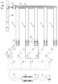
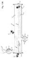
- Figure 1 shows a diagrammatic overview of a system or apparatus and a process for manufacturing snack food products according to the present invention, the process being continuous, but shown here in three consecutive lines, for the sake of illustration.
- Raw material is received by means of a bin 0 that is lifted up into the storage hopper with conveyor 1.
- the raw material can be washed, semi-washed or unwashed when received and can include any selection from various vegetables.
- Typical vegetables for use as raw materials in the process are: potato (including its cultivars such as B1, B13, van der Plank, Up-to-Date, Rosetta, Hertha, Undumbi, Congo Blue), sweet potato, parsnip, butternut, beetroot, mangle, sugar beet, carrot, zucchini, onion, sweet peppers, chilli, tomato, celeriac and pumpkin - each with its various cultivars.
- potato including its cultivars such as B1, B13, van der Plank, Up-to-Date, Rosetta, Hertha, Undumbi, Congo Blue
- sweet potato parsnip
- butternut beetroot
- mangle sugar beet
- carrot zucchini, onion, sweet peppers, chilli, tomato, celeriac and pumpkin - each with its various cultivars.
- the selection of the vegetable raw material depends on the seasonal availability of the vegetables.
- the are other vegetables available that are not mentioned which could also be used as well as fruits and proteins from collagen, sinew and skin e.g. fish skin, fish
- Fresh vegetables are supplied to a storage hopper 1. From the storage hopper with conveyor 1, the raw material is conveyed and transferred into a de-stoner and washer 2. The raw material exits the washer 2 into a hopper and conveyor 3 and is elevated into a storage hopper 4 that feeds the manually operated sorting table 5. This is where it is conveyed at a constant speed for the manual checking of the product for any contamination (eyes and any bruising that may have occurred in transportation) and removing it to clean the raw product before the final wash. The raw product is also sized at this stage so that the pieces of the raw product have generally uniform sizes and are ready for slicing. The raw material is then conveyed into a final washer 6.
- the washed raw material then goes into an elevator 7 (such as a bucket elevator).
- the elevator deposits the material into a hopper 8.
- the material is moved into a slicer 10 by means of the vibration provided by a vibrating conveyer 9. It then falls onto a conveyor belt 11 which feeds the material into a tumble powder applicator 12.
- the powder is fed through a dispensing mechanism from the hopper of a powder applicator 13 over the tumbling vegetables that then exit and fall onto a vibrating table conveyor 14.
- On this vibrating table conveyor 14 the raw material is then separated as individual pieces side by side as one layer by the movement of the vibrating table conveyor 14.
- Manual quality control 15 ensures that there are no slices with double layers and quality control at this point will ensure that there are no contaminated or rotten particles beyond this point.
- the vibrating table conveyor 14 feeds the loading area of a blanching belt 16 that leads into a blancher-dryer 17.
- the manual quality control 15 can also load the blancher conveyor 16 while ensuring that there is a tightly fitted layer of side by side vegetable slices on the blancher conveyor 16.
- the operation of the blancher-dryer 17 is described in more detail below.
- the product moves away from the blancher-dryer 17 and is conveyed up by a means of a lift 19 that feeds a hopper 20 that vibrates and moves the product forward at a specific rate to load a batch conveyor 21 that has a portion flight or bucket loading system to transfer the product into the hopper of a vacuum fryer 23 at a specified rate.
- the product is loaded by the hopper with controlled valves 22 that feed the vacuum fryer 23.
- the product is removed from the vacuum fryer 23 by means of a valve controlled outlet chute 24 of the vacuum fryer 23.
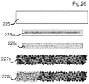
- Product falls onto a conveyor belt 25 to a vibrating feed 26 which feeds a rotary seasoning applicator 27.
- the seasoning is fed through a dispensing mechanism from a hopper 28 over the tumbling snack food that then exits into a hopper 29 that feeds the snack food into a bucket or flight conveyor lift 30.
- the bucket or flight conveyor lift 30 feeds the snack food onto a succession of vibrating conveyors 31 and 32.
- the snack food is then conveyed to a multi-head scale 33 and then falls through a metal detector 34 and enters a form fill machine 35 where it is packed and sealed. Thereafter it is conveyed to a packing station 36.
- This system shown in Figure 1 has the structure for a complete computerised integrated manufacturing process.
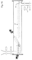
- Figure 2 shows a plan view of the components of numbers 0 to 19 in Figure 1 , which includes the vegetable washing and sorting and the processes of blanching and drying the vegetables.
- the numbers in Figure 2 correspond to the numbers in figure 1 .
- the blancher-dryer 17 can be a microwave, radiofrequency, infrared or solar heated system, but in the illustrated embodiment, the blancher-fryer uses an oil burner to heat oil that is used as a heat transfer medium.
- the embodiment of the invention shown in Figure 2 has multiple processing lines. Multiple lines could be used, for example in a case in which the final product consists of a mixture of vegetable crisps. Separating the vegetables into parallel lines at the primary stage of processing assists in ensuring that colours and flavours do not contaminate one another. For example, beetroot, butternut, carrot, parsnip, sweet potato or other vegetables could be separated.
- Number 37 indicates a conveyor used in the case of multiple lines, to convey the material to the lift 19.
- the product produced by the stages of the process shown in Figure 2 can be stored for an extended period before proceeding to the rest of the process. Allowance can be made for storage of the partially processed product after the blanching and drying stage. These stages up to the blanching and drying stage and the subsequent stages may therefore be conducted at separate premises and 42 shows storage bins which could be used if the product will be stored prior to further processing. Depending on the characteristics of the product at this stage, the product may be stored for several weeks or months under refrigeration. This could be required if the moisture content of the product would result in spoilage under non-refrigerated conditions. Alternatively or additionally, preservatives such as sodium metabisulphite and/or other antioxidants or preservatives could be added at the slicer 10 or the powder applicator 13. The period of refrigerated storage could be in the range from 24 hours to 9 months
- a storage temperature of 5-30 °C could be suitable. If the product contains no preservatives, the product should preferably be stored at 0-12°C until further processing. Lower temperatures in the range of 2-4°C are preferred.
- Sodium metabisulphite could be added to the powder blend before blanching to reduce the risk of contamination during storage at room temperature.
- This storage will allow a fruit or vegetable farmer to conduct the initial process of the blanching and drying at the farm where the fresh fruit and/or vegetable is harvested and is immediately processed, thereby eliminating the exposure of the raw fruit and/or vegetable to uncontrollable transport and pre-holding conditions such as high temperature which contribute to spoilage, sugar build-up, over ripening, or time delays which may result in the conversion of starches to sugars.
- the partially processed product may be stored under controlled conditions, such as refrigeration, if deemed necessary due to the moisture content and other characteristics of the specific product.
- the blanched vegetable and/or fruit can then be supplied from the farmer already partially processed to a snack food processing plant comprising the vacuum fryer 23 and packaging equipment.
- the vegetable farmer is then able to prepare the vegetable as the seasonality of the vegetable allows.
- the farmer can then sell the partially processed vegetable to the snack food processing plant through the year at a beneficial price structure.
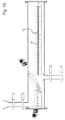
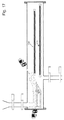
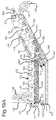
- Figure 3 is the independent vacuum frying processing line where the pre-dried raw material is processed into a snack food.
- FIG 4 is a detail view of the area indicated by number 43 in Figure 2 . This shows the configuration of the slicer 10, powder applicator 12 and vibrating table conveyor 14 onto the blanching belt (or loading bed) 16 ensuring that the vegetables entering the blancher-dryer 17 are in one layer and are tightly packed.
- Figure 5 shows a schematic side view of a blanching and fluidized bed inside the blancher-dryer 17.
- the product enters the blancher-dryer 17 on the loading bed 16 and the product passes through a blancher 44.
- the product is then air dried 45 at temperatures between 75-80°C and then the surface dried slices enter a fluidized bed 46.
- the product slices are kept in motion within a high velocity fluidized bed 47 while being conveyed in a perforated conveyor, with hot air ranging from 55-80°C 48 being passing through the fluidized bed from below.
- the dried product has a specified moisture content ranging from 3-25%. It is then removed with a removal conveyor 50 and then the product exits 51 for the destination for storage or further processing.
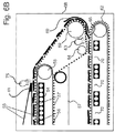
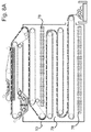
- FIGS 6A and 6B show alternative apparatus for use inside the blancher-dryer that is generally identified by reference numeral 17 and is also referred to herein as a "blancher".
- the blancher 17 includes an upper cooking area 52, where the raw product is partially cooked or blanched, and a lower area 53 where the blanched product is dried.
- a heat source is provided in the form of a bed 54 comprising an array of passages through which heating oil or other heating fluid is circulated.
- the oil in the oil heater 54 is maintained at a constant temperature of about 180°C.
- the heat source 54 could be any one of a variety of heat sources, e.g. it could include microwave emitters, radio frequency, infrared, resistance heaters, combustion heaters, or the like and the position of the heat source can be varied.
- an endless top belt 55 is provided between pulleys and the top belt is of a generally impervious construction and is coated with a friction resistant (“non-stick”) and heat resistant material such as PTFE (Teflon). As shown in Figure 6A , the top belt rotates so that it travels from left to right in its bottom run and from right to left in its top run (counter-clockwise).
- a carrier belt 57 is provided on the outside of the heater belt 56 and rotates in the same direction as the heater belt.
- the carrier belt 57 is perforated and defines numerous apertures (e.g. it can be of a mesh construction) and is also coated with a friction and heat resistant material such as Teflon.
- the heater belt 56 and carrier belt 57 are in close contact in their top runs and separate at a separation roller 58.
- the carrier belt 57 continues at a downward angle, carrying the pre-blanched slices 61 into and between the roller 59.
- the blanched product reaches the roller 59, it is held in contact with the carrier belt 57 while being inverted, by a bubble plate curved sheet 60 used as a shield, until it leaves the shield and is received on top of a drying belt 62 and is thus sandwiched between the carrier belt 57 from above and the drying belt 62 from below.
- the product slice Shortly after leaving the roller 59, the product slice travels past the air nozzle 63 which assists in transferring the slice from the carrier belt 57 to the drying belt 62 with a gentle air flow.
- the transfer of the product slice 65 from the carrier belt 57 to the drying belt 62 is further assisted by a sharp turn of the carrier belt 57 around a roller 64.
- the upper cooking area 52 of the blancher 17 and the lower drying area 53 are not sealed off completely, but are separated by their construction - as represented in Figure 6A by a dividing wall 67.
- the area 53 below the wall 67 is supplied with air that is heated and dried and the temperature and humidity of the air is controlled.
- Four drying belts 68a, 68b, 68c, and 68d are provided in the drying area of the blancher.
- the drying belts 68a and 68b are running at the same speed, however drying belts 68c and68d have independent speed control to be allow control the final moisture content of the product 69 exiting the drier 53.
- the drying belt 68a is of a construction that allows air to pass through it with ease - e.g. it may be of a Teflon coated mesh construction, same or similar to the carrier belt 57.
- the slices of raw product 71 reach the blancher 17, they are received on top of the carrier belt 57 (with the heater belt 56 immediately below it) at the receiving end 72.
- the raw product slices 71 then travel on top of the carrier and heater belts 57, 56 and the bottom run of the top belt 55 makes contact with the product slices, before they travel to the oil heater 54.
- the top belt 55 serves to keep the product slices in place and to contain moisture and it need not make firm contact with the product slices.
- the heater belt 56 need not make contact with the carrier belt 57. Effectively, the product slices are carried on the carrier belt 57 generally sandwiched from above and below, by the top and bottom heater belts 56, 57.
- the belts 55,56,57 are each about 1200mm wide and extend generally across the inside of the upper part of the blancher 17 and the gap between the top belt 55 and heater belt 56 is about as much as the thickness of the slices - e.g. typically of the order of 1 mm to 3mm.
- the product slices travel in this sandwich arrangement along with the top, heater and carrier belts 55, 56, 57, all travelling at the same speed, past the oil heater source 54, as shown by reference number 73 in Figure 6A .
- the oil heater 54 is not situated directly below the top run of the heater and carrier belts 56, 57, but is spaced below these belts in close enough proximity to heat the product slices carried on these belts.
- the heater elements 74 run from side to side of the individual drying beds with a gap in between 70.
- the heat element ensures even heat distribution over the width and the length of the belt, this ensures that the centre of the drying belt and the edges are equally heated throughout the drier, the heating element of the drier is of the same type as element 54.
- the temperature is controlled by valves that can reduce the oil flow through the individual set as differentiated by 68a and 68b at a temperature range from 65 -80°C.
- the belts 56, 57 proceed towards a belt washer 38. While the product slices are being blanched, any drops that may form pass through the apertures in the carrier belt 57 and land on the heater belt 56 and may caramelize and contaminate the belts if passed through the system continually.
- the belt 55 As the belt 55 exits the product blanching process, it passes around a rounded "knife-edge" 41, with an air blower 75 directly at the exit point of the product. This sharp rounded edge 41, assisted by the air blower 75, ensures that there is no product left sticking to the belt 55.
- mister 76 that sprays a fine mist of water onto the raw product before it enters the blancher 17, if required.
- This fine mist of water assists in adding a small percentage of moisture to the raw product.
- the reason for this would be that some vegetables are aged and lacking in the required moisture content for the process. For e.g., aged parsnip, aged butternut and aged sweet potato with a honeycomb inner structure. The process allows for fresh and well-aged vegetables that verge onto a dry and even a rubbery texture.
- Belt 56 is separated by means of roller 58.
- the belt 57 however continues further around roller 59 and 64.
- a product slice is shown in Figure 6B , with reference number 65, in a position between the air nozzle 63 and the sharp turn of the carrier belt 57.
- Figure 6C shows an alternative arrangement to that shown in Figures 6A and 6B , in which the belt 56 is allowed to continue around roller 59, and is separated before the air nozzle 63 by means of a roller 66. This allows adequate space to incorporate the air nozzle 63 between roller 59 and roller 64. Further the explanation as referring to 6A and 6B is applied.
- Figure 6D shows an alternative arrangement to those shown in Figures 6A to 6C , in which the bubble plate shield 60 is replaced by a motorized belt shield168.
- the belt 56 is separated by means of a roller 58.
- the belt 57 however continues further around the rollers 59 and 64.
- a product slice is shown in Figure 6D , with reference number 65, in a position between the air nozzle 63 and the sharp turn of the carrier belt 57.
- Drive rollers 169 and 171 are connected by chains and mechanically driven, to drive the belt shield 168 that is made of the same material as the top belt 55 and that extends around idler rollers 170.
- a knife edge rotating fine roller 172 is also provided and all five driven rollers 169,171, and 172 are geared down to run at the same speed.
- a scraper 173 ensures that no product 65 continues beyond this point along the belt 57. At the outside at the loser edge of the belt 68, there may need to be a supporting pulley 190 to nip the belt around the knife edge roller 172, yet ensure that the belt remains limp around the drive 59.
- a spray mechanism 76 is provided which can be applied to moisten the vegetables if they are fairly old and dry (such as aged butternut, rubbery parsnips and honeycombed butternut).
- radiator fin sections used as heat exchangers 82, running the full length of the drier, side by side.
- pipes 83 running through the fin sections, hot oil 84 is passed through these pipes.
- baffle panels 80 and three internal baffle panels 81 that rest in between and on the radiator fins 82.
- the air is passed from the bottom 85 of the unit and through the heated fins 82, thereby heating the air.
- the air is forced upwards by the fans from the bottom area 85 and as the air passes through the fins 86 it is heated and is pushed upwards towards the product above. This heated air passes over and around the slices reducing the moisture content of the product.
- the relative humidity of the drier can be controlled to reduce the case hardening of the product slices.
- This configuration is an embodiment of the vacuum fryer 23 as shown in Figure 1 .
- Raw material can enter the vacuum fryer 23 in three different forms:
- This raw material 89 is the raw material that has been blanched and dried, then pre-weighed, and loaded into a rotary tumbler while oil is sprayed over the surface of the raw material, coating the slices.
- the oil content can vary from 3-20% and this is controllable. This is a batch process. The prepared product is stored ready for vacuum expansion.
- the raw material 90 is the raw material that has been blanched and dried and brought to a specific moisture content ranging from 12%-25% that is required for the following process. No oil is added to the product.
- the raw material 89, 90 enters 87 the fryer 23.
- the material enters by means of a set valve gates 112.
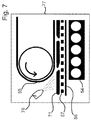
- the product enters a hopper 92 within a microwave vacuum chamber 109 and there is an opening 93 through which product passes by means of friction from a conveyor belt 88.
- the hopper 92 in the vacuum chamber 109 prevents the material from entering all at once.
- the product enters through an opening 93 of the hopper that is conveyed on the belt 88 by means of friction and moves towards a rotary brush 94 (or multiple configurations thereof) above the conveyor belt 88 that controls the amount of product 103 passing through towards the microwave.
- the product enters a labyrinth or prison 96 at 95 through a gap 102of about 5mm-30mm. This assists in ensuring that the product is evenly distributed onto the conveyor belt 88 for microwave heat transfer on the product.
- An upper run 106 of the conveyor belt 88 runs through the microwave unit and on its return, its lower run 107 runs underneath the microwave unit.
- the conveyor belt 88 is a continuous Teflon coated belt.
- the internal microwave unit 108 is constructed from household higher powered microwave ovens 97 which are connected side by side. Each microwave oven has its own individual control and magnetron. All unnecessary components of the microwave ovens are removed and the controls for the magnetrons are linked up to a central control for the entire internal microwave unit 108.
- An outer housing 105 of the microwave unit 108 is of a porous faraday cage structure, allowing the moisture to pass out of the microwave unit 108 into the vacuum chamber 109.
- the holes in the faraday cage structure105 are 0.5mm-5mm in diameter.
- the top, bottom and sides of the internal and external microwave structure are of a suitably coated faraday cage.
- a prison 96 is situated at the entrance and exit to the microwave section with the continuous conveyor belt 88 moving through the microwave ovens 97.
- the product 110 enters the microwave unit 108 it undergoes a cooking process and exits the microwave unit at 111 continuing through the prison 96 towards the drop-off point 101 onto a discharge belt 98.
- the product is then accumulated 104 to a suitable level for discharge into the drop off point 99.
- the discharge belt 98 travels at a different speed from the microwave belt 88 loading the belt to a suitable discharge for the batch exiting process 99.
- An alternative embodiment of the invention can be incorporated as radio frequency as the mechanism for heat expansion under vacuum of the product.
- the oil contents of the final product can be zero (owing to the fact that oil need not be added to the product before heating, as described above), but it may be desirable to add oil, e.g. be spaying on to the product before the heating step.
- the quantity of oil can still be low and fat contents of about 8% to 10% are considered to be acceptably low and to enhance product palatability. Lower fat content has health benefits.
- FIG. 1 This shows an alternative embodiment of the vacuum fryer 23 as referred to in Figure 1 . It is a cross-section of an infra-red expanding unit.
- the raw product slices 89, 90 enter the fryer 23 at 87.
- the product enters from the hopper and valve configuration 114 which is off-set from the axis of the vacuum chamber 109 to enable the product to fall through the guiding chute 115 into the vacuum chamber 109.
- the product falls onto a tumbling interlinked weighted hinge belt 116 which is moving in an anti-clockwise direction 188.
- the hinges are positioned upwards120 in the hinge belt 116 with the smooth side 121 in direct contact with the rollers 122.
- the belt 116 forms a concave recess123 into which the product is deposited onto the belt 116.
- the hinges on the hinge belt 116 allow the product to rotate and bring the product slices into contact with the infra-red rays on a continuous basis.
- the infra-red unit 119 heats and cooks the product as the hinge tumbler 116 rotates the product, and as it rotates the individual product slices receive an even dosage of the infra-red heating 124.
- hinge-belt 116 will move in a clockwise direction 189 when a batch is being discharged.
- a shield 118 will assist the product to fall onto the discharge belt 117.
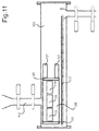
- Figure 11 is a side view of an infra-red embodiment of the invention.
- This shows the infra-red configuration as a batch system, and the infra-red units 119 are placed side by side in front of the hinge belt and roller configuration 126.
- the infra-red unit configuration is shown as three units side by side but are not limited to this number.
- the flow and systems are similar to figure 9 .
- the difference in configuration is that of the discharge belt 117, and infra-red unit 119 as described in figure 10 .
- the infra-red units in this configuration have flat side barriers 125 stopping product from falling off the edge of the hinge belt and roller configuration 126.
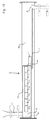
- Figure 12 is a side view of the vacuum unit of a continuous line for the infra-red 119 configuration.
- the flow and systems of the unit are of similar nature to that of Figure 11 however the unit runs as a continuous line instead of a batch system.
- the vacuum unit is positioned at a downward angle towards the product exit 99. Lowering of the discharge end of where the product exits the unit results in a faster throughput of the product.
- the continuous infra-red unit 126 has one flat side barrier 125 and one belt drive 127 as it is a continuous unit.
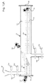
- Figure 13 illustrates the valve system of the vacuum fryer, and a drying system for the fried product.
- the drive (i.e. motor and gearbox) 160 for the fryer's screw shaft and the drive 161 for the exit screw shaft are also shown.
- the drying belt also has a drive 192 mounted outside the vacuum chamber.
- This drying system consists of a belt 135 with flights and a trough 166 with holes in the sides of the trough along its length to allow moisture to escape.
- the holes are slightly higher than the level of the product which is being conveyed along the belt, and therefore the product does not fall out of the holes.
- the product enters the vacuum fryer 23 at the inlet 89 and exits at the outlet 99. Both the inlet and the outlet have valves 128a, 128b, 129a and 129b which impede the transit of the product.
- valves 128a and 128b are synchronised to open at the same moment whilst the valves 129a and 129b remain closed.
- the valves 129a and 129b are also synchronised to open at the same moment whilst the valves 128a and 128b remain closed. The opening and closing of these valves allow a batched portion of not-yet-fried product to enter the vacuum fryer as a batched portion of fried product exits.
- the fluctuation in pressure within the vacuum chamber is negligible, because the inflow of a small amount of regular air is only momentary when 129a is opened and when 128b is opened.
- the functionality is identical to 13A, but using a rotating valve system for loading and unloading of raw material.
- valves of the portion of the unit marked 164 and rotating drum 164 are under vacuum and needs to be equalised to ambient pressure prior to exiting 164. This pressure is regulated through a valve system to ensure the correct pressures in 164, and to allow the product to exit the fryer without crushing and smashing because of the sudden vacuum to air pressure release.
- Figure 14 shows two types of conveying belts, one with flights without a heater 135 and one with flights with a heater 136, one conveyor belt without a heater and excluding the flight 137 and a conveyor with a heater 138.
- Reference 130 refers to a flat surface of the conveying belt where the product rests on the belt and 131 refers to an upright flight that can vary from 20mm-250mm in height.
- Reference 132 refers to a gap between the flights 131 that can vary between 50mm-300mm.
- the unit 135 does not have a heater in or around it and is used to cool and increase the holding time of the product under vacuum; this is related to the length of the flight conveyor belt.
- Conveyor 136 employs a heater 133 in the centre of the unit, in the top run from left to right the heater is below the belt and in the bottom run from right to left the heater is above the belt. This is to ensure that the product does not cool too fast in one direction under vacuum, ensuring that water vapour in the vacuum chamber will not condense back onto the product. At the bottom set of flights, the cooling action will continue but not to its full possible extent.
- Belt 137 is a flightless belt without a heater, the product flows out from the fryer continuously on the belt.
- Belt 138 is a flightless belt with a heater.
- Figure 15 is similar to Figure 13 , but shows a different configuration around the drying belt 135. There is no trough. Instead, the product falls from the belt into the exit hopper 164, which in this case is positioned at the end of the chamber. A baffle 193 guides the product as it drops off the end of the belt.
- Figure 16 is similar to Figure 13 , but in this configuration there is also provided a heat element 133 beneath the belt 136. The heat helps the fried product to dry.
- Figure 17 is also similar to Figure 13 , but shows two belts 138 supplied with heat elements beneath them.
- the product falls from the top level belt onto the lower level before exiting the chamber.
- the belt has no flights. If the vacuum chamber is big enough, there could be belts on further levels. Some or all of these belts may have heat elements.
- the heating could be electrical plate heating or oil heating or other conventional means of heating.
- One example is in the case of products such as fruit, which have a high sugar content, in which case it is difficult to release the moisture entrapped in such products.
- the fruit entering the vacuum fryer may have been pre-dried by conventional means or blanched.
- a chute 194 between two vacuum fryer chambers. If desired, a batching of product pieces may be facilitated between the two chambers by a screw feed or a valve gate system (not shown) within the chute.
- the double fryer system is used to process high sugar products e.g. an air dried watermelon which have a high osmotic pressure.
- the double frying system removes the moisture whilst expanding the product without caramelization.
- the product is fied, for example, for 6 seconds, then cooled and thereafter refried in the second fryer for another 6 seconds, then cooled and discharged.
- the product is moved through hot oil by means of a screw feed 149, and is removed from the oil by a second screw feed 150.
- the product may be immersed and removed by other means, such as by means of a basket, a belt, or a series of perforated buckets.
- the product enters the fryer after exiting the last gate valve 129a (as shown in Figure 13A ).
- the pre-dried product 139 passes through a chute 182 and enters a fryer 173.
- the chute 182 is not attached to the wall of the vacuum chamber (186 as shown in Figure 19B ).
- the specified temperature for the pre-heated oil in the fryer 173 could be in a range of 140° C to 195° C, and the preferred temperature could be 150° C as it enters the fryer at an oil entry point 174.
- the housing 154 of the fryer is preferably composed of two cylindrical stainless steel pipes which intersect at an angle as shown.
- a longitudinal aperture 176 extending from the top of the first pipe to the second pipe, allows moisture and steam to escape from the product into the vacuum chamber surrounding the fryer.
- the pipe does not have an opening beyond the point 177. However, in a different embodiment, there could be one or more openings.
- the oil passes from a pipe 142 into the frying chamber (within the vacuum chamber) via an inlet 174, the supply being controlled by a regulator (shown as 178 in figure 19B ).
- the flow is regulated by an oil flow regulator at the outlet 175. This regulates the minimum and maximum depth of the oil within the frying chamber, as well as the speed at which the oil passes through the chamber.
- the temperature of the oil and the turbulence can be controlled to optimise and standardise the product quality.
- the oil moves from the inlet 174 to the outlet 143 through the full length of the chamber.
- the inflow and outflow pipes can be detached at 142 and 143, allowing removal of the fryer from the vacuum chamber for cleaning and maintenance.
- the final product produced by this embodiment of the invention may have an oil content of 15 to 25%, but this would depend on the moisture content of the product upon entry into the fryer and other criteria.
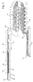
- the screw may have one or more flights. (This diagram shows one flight 159.)
- the flight 159 is perforated throughout its entire length.
- the holes in the flight 159 typically range from 2-8 mm in diameter to allow oil to pass through as the screw rotates.
- the holes are small and smooth enough to not damage or catch the product being fried.
- the screw feed 149 rotates, moving the product forward and contributing to a light mixing action beneath the surface of the oil flow.
- the flight 159 of the exiting screw feed 150 has similar holes.
- the screw shaft 149 is supported at one end by a metal cap 184 suspended from a bracket 147. The other end of the shaft is held in place by fitting into a rotary lip seal 140 in a closure plate 185 at the end of the fryer 173. The lip seal prevents oil from leaking out of the fryer.
- the machine which drives the screw shaft has a shaft of its own which extends all the way through the sealing plate and clicks into the end of the screw shaft 141 when the sealing plate is closed.
- the rotary lip seal should preferably be made of Teflon.
- the seal 140 and cap 184 remain stationary while the shaft rotates.
- the sealing plate is indicated in Figure 13A and 13B as reference number 162.
- the shaft of the exiting screw feed 150 has similar (but not identical) support fittings, with 145 being similar to 184 (but not removable), and 189 being similar to 141 as it fits into its drive shaft 155. There is also a removable supporting ring 153 suspended from a bracket to hold the shaft in place.
- the oil level is only up to the level of the screw shaft 146.
- the oil level, feed mechanism and oil regulation system contribute to ensuring that minimal oil is recycled and that fresh oil is introduced continuously without requiring the discarding of oil. All the oil is thus fully utilised in this process.
- the oil is not subjected to great fluctuations in temperature, which would result in an inefficient use of energy and would have other disadvantages relating to product quality.
- exiting screw feed 150 is that the flight which takes the product out of the oil is not subject to continuous cooling and heating as in the case of a belt or bucket removal system.
- One of the problems with cooling and heating is an inefficient use of energy and space.
- the top of the exiting screw feed 150 remains out of the oil at all times, and is therefore cool, allowing the product to cool. If the removal mechanism is hot at this stage, it would continue imparting heat to the product. This could result in adverse effects such burning, caramelization and increased acrylamide formation.
- scraper mechanism 148 made of any material deemed suitable. This material may be stainless steel. The scraper removes any unwanted particles or residue which may accumulate at the end of the horizontal shaft 149 before the product is taken upwards by the exiting screw feed 150.
- Figure 19B shows a detail end view of the fryer 173 in Figure 19A .
- a supporting frame179 which is welded onto the outside of the fryer.
- the supporting frame 179 assists in ensuring that the frying chamber does not distort when heated.
- the frame can also have wheels 180 on a rail 181 mounted onto the inner walls of the vacuum chamber 186. The wheels and rail facilitate ease of removal of the fryer from the vacuum chamber for cleaning and maintenance.
- oil inlet pipes 142 and 143 which run through the wall of the vacuum chamber and are welded onto it.
- Figure 19C illustrates apparatus used in maintaining oil temperature in the oil frying zone of the Fryer 173 shown in figure 19A .
- the product can take up to 25 seconds to fry (see cool zone B) and the oil can cool during the 25 second period, and when the temperature of the oil drops too low, hot oil is added to maintain the heat up to the end of the frying process.
- hot oil is added via openings into the fryer from one or two pipes that are mounted above the cool zone B near the end of the oil frying area through a pipe system as shown in the drawing.
- To control oil flow valves C1 and C2 will allow the required oil pressure to be maintained while passing through the pipes.
- Oil flow restrictor sleeve D To control the oil flow into the required area, sleeve D is used. This sleeve has a tight fit around the pipe and can be rotated and can be placed over an opening E or a portion of the opening as a restrictor or as a closing device thereby controlling the oil flow into the required area.
- This figure shows the vacuum fryer and supporting systems (described in detail areas in Figures 21 , 22 and 23 ).
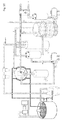
- Figure 21 shows the oil supply and heating system for the vacuum fryer (with the other components shown in Figure 20 removed from this illustration for the sake of clarity).
- the system has been designed to be energy-efficient in that the oil used for frying is itself used in other parts of the heating system to impart and preserve heat.
- a manually operated valve 196 to close off the supply for cleaning and maintenance.
- the oil passes into a jacket chamber 197 which partially or completely surrounds the oil reservoir tank 198.
- a jacket chamber there could be a heat exchanger pipe which extends around the tank, or is enclosed by it, or is immersed in the tank.
- the oil is pre-heated within this chamber by the heat of the oil in the oil reservoir tank 198.
- valve (not shown) between the jacket chamber197 and the reservoir tank itself, so that when the level of oil in the reservoir tank 198 drops below a certain level, the valve opens and draws in more oil from the jacket chamber.
- This drawing in of fresh oil is the result of a vacuum which is drawn throughout the oil supply system. Thus the oil is mostly pulled rather than pumped through the system.
- An oil pump 199 pulls oil to be used for frying from the reservoir tank 198 to a conventional plate heat exchanger 183.
- the oil is preferably heated to a temperature of 150 degrees C and maintained at this temperature at all stages of its passage through the system.
- the heat exchanger 183 has an inlet 200 and an outlet 201 for oil that acts as a heating medium and this oil is of a different type from the oil used for frying.
- valve 202 When the system is started up, the valve 202 is closed and the valve 201 is opened. Thus the oil circulates from the reservoir tank 198 to the heat exchanger 183 down through the open valve 203 until a constant desired temperature has been established.
- valve 201 is closed and the valve 202 is opened allowing oil to be drawn into the oil fryer 173. (The outer vacuum chamber is not shown in this illustration.)
- the oil supply to the fryer 173 is controlled by means of a level switch flow regulator 178.
- the exiting oil is drawn by a pump 204 to an oil filter 206a.
- a fine filter 206b is used to remove particles prior to the oil entering the heat exchanger 183.
- FIG 22 shows the vacuum system for the vacuum fryer (with the other components shown in Figure 20 removed from this illustration for the sake of clarity).
- the vacuum pump 209 is preferably a liquid ring vacuum pump. There is a water supply 210 to the vacuum pump to cool the pump.
- the control valve 211 is a hand-controlled valve or a non-return valve. In an emergency (such as a power failure), this valve ensures that water is not sucked through into the fryer.
- the vacuum pump removes air from the vacuum chamber 186 and simultaneously also from the oil filter 208 and the oil reservoir tank 208.
- the water, water vapour and air are discharged at 215.
- a safety tank 212 ensures that any water or oil which should not be in the system can be captured and released via a tap. (This is shown in greater detail in Figure 20 .)
- Condensers 213 remove oil and water vapour if necessary.
- Water released by the vacuum pump is returned to the water supply via a pipe 223.
- FIG 23 shows the water cooling system for the vacuum fryer (with the other components shown in Figure 20 removed from this illustration for the sake of clarity).
- a compressor 216 is connected to a cooling element which is immersed in the water in a supply tank 224.
- a motorised paddle mixer 217 helps to circulate the water.
- the cooled water is drawn into the vacuum pump at 210.
- a water pump 218 draws water into a jacket chamber 219 which surrounds the vacuum chamber 186.
- the water which is pumped to the jacket chamber returns into the tank via a pipe 222. Water from the vacuum pump is also returned to this water supply tank 224.
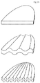
- the vegetable or fruit pieces could be sliced into various types of slices prior to processing. Examples are illustrated here.
- a raw fruit or vegetable slice is typically in the range of 0.8 mm to 12 mm thickness. The thickness should be standardised to ensure consistent product quality.
- the present invention is aimed at producing products with characteristics such as these illustrated here.
- 225 shows a cross-section of the shape of a neat raw vegetable or fruit slice prior to processing.
- 226a and 226b are slices of fruit or vegetable after blanching and drying (also shown in cross-section). The dark area indicates that the inside has more moisture than the outside.
- 227a shows how the slice 226a is expanded when fried.
- 228a shows the size of the bubbles.
- 227b shows how the slice 226b is expanded when fried.
- 228b shows that the slice has particularly large bubbles.
- 226c indicates the even distribution of moisture after the blanched, dried product has been stored for some time. When this product is fried, the result 227c is more even. The consistent size of the bubbles is shown in 228c.
- the pre-dried product can be passed through a fine mist spray or steam tunnel, to add moisture to the surface of the product slices prior to frying.
- steam can be employed on the lift 21 as shown in Figure 3 or the lift can be replaced by a screw feed conveyer that mixes and adds moisture to the slices before entering the fryer.
- a preferred alternative is a separate continuous steam or water vapour tumble mixer. The product exiting the tumble mixer will fall into the hopper of 21.
- Controlled moisturising of the slices prior to frying When product leaves the blancher-dryer 17, and/or has been stored for a longer period with low moisture content in the region of 8% to 15%, the slices could be too dry to expand correctly in the fryer. Internal moisture needs to be raised from between 15% to 25%. This is done by using an automated mixer which is a continuous steam or water vapour tumble mixer or a moisturising vibrating fluidised bed (21 c as shown in Figure 3 ) which accurately doses the specified amounts of moisture to the product. Products that are dense can be stored to allow the moisture to equalise through the slices, prior to frying.
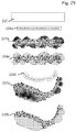
- fruit slices are shown in cross section. Textural additions can be provided prior to drying and then remain adhered to the product during the rest of the process. Instead of plain fruit slices 229, there may be fruit slices which have a layer of phyllo pastry on one side (230), with phyllo pastry on both sides (231), fruit slices crumbed on one side (232) or crumbed on both sides (233). Starch powder or other textural additions may also be used.
- the present invention can be used to make crisp snack food products from various ingredients, including vegetables, fruits, or gelatinizable proteins from fish. This does not exclude formulated products with a multitude of ingredients which are mixed to produce one product which is then pre-gelatinized. Therefore, the invention allows production of a low fat flavoured soup which is thickened with starches, then dried on a flatbed producing a sheet and cut into portions, which can be expanded to produce a crispy crunchy snack using this system.
- the main challenge is to expand a product without caramelizing it into a deep brown colour or burn it in the process.
- moisture content of the product needs to be controlled before it enters the fryer, the moisture on the outer surface of the product needs to be controlled before entering the fryer, and moisture needs to be removed from the product whilst it is in the fryer, to produce a crispy, natural coloured crisp without caramelizing or burning.
- Sweetness is normally measured in terms of total soluble solids (TSS) content in Brix. In most fruits and vegetables, sugar makes up the main component of TSS which is thus a reasonable indicator of percentage sugar levels. TSS is measured using a refractometer or a hydrometer and refractometers are easy to use, even for inexperienced operators.
- the crop with a higher refractive index will have a higher sugar content, higher mineral content, higher protein content and a greater specific gravity or density. This adds up to a sweeter tasting, more mineral nutritious food (maximum nutritional value) with a lower nitrate and water content and better storage characteristics.
- potatoes with a sugar content that exceeds 0.2% is regarded as not being suitable for frying, but the present invention allows foods (including potatoes) with much higher sugar contents to be used to prepared crisp food products.
- the ratings (POOR, AVERAGE, GOOD and EXCELLENT) mentioned in the tables below relate to the shelf life of raw foods that can be used to manufacture snack food products according to the present invention.
- the ratings do not refer to the processing capability of the raw foods - the present invention can be used to process foods despite any of these fluctuations.
- Table A Vegetables POOR AVERAGE GOOD EXCELLENT Beets 6 8 10 12 Beetroot Bell Peppers 4 6 8 12 Butternut squash Broccoli 6 8 10 12 Carrots 4 6 12 18 Cauliflower 4 6 8 10 Celery root Green Beans 4 6 8 10 Hot Peppers 4 6 8 10 Kohlrabi 6 8 10 12 Mirliton Mangel beets Onions 4 6 8 10 Parsnip Potatoes, Irish 3 5 7 8 Potatoes, Red 3 5 7 8 Potatoes, Sweet 6 8 10 14 Romaine 4 6 8 10 Rutabagas 4 6 10 12 Squash 6 8 12 14 Sugar beet Turnips 4 6 8 10 10 Table B: Protein / Crackling POOR AVERAGE GOOD EXCELLENT Fish skin Fish tongue Fish Kokotxas Tendon or Sinew Table C: Fruit FRUIT POOR AVERAGE GOOD EXCELLENT ACID Apple (Sour) 6 10 14 18+ Malic Apple (Sweet) 10 14 18 22+ Malic Apricot 6 12 16 23+ Malic Banana 8 10
Landscapes
- Chemical & Material Sciences (AREA)
- Engineering & Computer Science (AREA)
- Life Sciences & Earth Sciences (AREA)
- Food Science & Technology (AREA)
- Polymers & Plastics (AREA)
- Health & Medical Sciences (AREA)
- Nutrition Science (AREA)
- Chemical Kinetics & Catalysis (AREA)
- General Chemical & Material Sciences (AREA)
- Wood Science & Technology (AREA)
- Zoology (AREA)
- Oil, Petroleum & Natural Gas (AREA)
- Preparation Of Fruits And Vegetables (AREA)
- General Preparation And Processing Of Foods (AREA)
- Frying-Pans Or Fryers (AREA)
- Confectionery (AREA)
- Freezing, Cooling And Drying Of Foods (AREA)
Applications Claiming Priority (2)
| Application Number | Priority Date | Filing Date | Title |
|---|---|---|---|
| ZA201109473 | 2011-12-22 | ||
| PCT/IB2012/057634 WO2013093886A1 (en) | 2011-12-22 | 2012-12-21 | Method and apparatus for the preparation of a crisp food product |
Publications (2)
| Publication Number | Publication Date |
|---|---|
| EP2793666A1 EP2793666A1 (en) | 2014-10-29 |
| EP2793666B1 true EP2793666B1 (en) | 2016-04-06 |
Family
ID=47741195
Family Applications (1)
| Application Number | Title | Priority Date | Filing Date |
|---|---|---|---|
| EP12824916.6A Not-in-force EP2793666B1 (en) | 2011-12-22 | 2012-12-21 | Method and apparatus for the preparation of a crisp food product |
Country Status (8)
| Country | Link |
|---|---|
| US (1) | US9510605B2 (ja) |
| EP (1) | EP2793666B1 (ja) |
| JP (1) | JP6243348B2 (ja) |
| AU (1) | AU2012356034B2 (ja) |
| BR (1) | BR112014015403B1 (ja) |
| IN (1) | IN2014DN06147A (ja) |
| WO (1) | WO2013093886A1 (ja) |
| ZA (1) | ZA201405350B (ja) |
Families Citing this family (20)
| Publication number | Priority date | Publication date | Assignee | Title |
|---|---|---|---|---|
| US10405506B2 (en) | 2009-04-20 | 2019-09-10 | Parabel Ltd. | Apparatus for fluid conveyance in a continuous loop |
| WO2016062513A1 (en) | 2014-10-23 | 2016-04-28 | Koninklijke Philips N.V. | Apparatus and method for preparing food |
| WO2016201379A1 (en) | 2015-06-10 | 2016-12-15 | Parabel Ltd. | Methods and systems for extracting protein and carbohydrate rich products from a microcrop and compositions thereof |
| CA2986919A1 (en) | 2015-06-10 | 2016-12-15 | Parabel Ltd. | Apparatuses, methods, and systems for cultivating a microcrop involving a floating coupling device |
| BR112017026539B1 (pt) | 2015-06-10 | 2022-01-25 | Peter Sherlock | Processos para produzir um produto absorvente a partir de uma microcultura, leito animal criado a partir do processamento de uma microcultura e produto de fralda |
| US10961326B2 (en) | 2015-07-06 | 2021-03-30 | Parabel Nutrition, Inc. | Methods and systems for extracting a polysaccharide product from a microcrop and compositions thereof |
| CA2935251C (en) * | 2015-07-09 | 2022-09-13 | Tna Australia Pty Limited | A continuous fryer with linear flow |
| MX2018001687A (es) | 2015-08-10 | 2019-06-06 | Parabel Ltd | Metodos y sistemas para extraer proteina de acido oxalico reducido de especies acuaticas y composiciones de la misma. |
| BR112018004808A2 (pt) * | 2015-09-10 | 2020-10-27 | Parabel Ltd. | produto de proteína de alta concentração, composição de proteína e método para fabricar uma composição de proteínas |
| JP6660211B2 (ja) * | 2016-02-29 | 2020-03-11 | キユーピー株式会社 | 野菜含有組成物及び野菜含有組成物の製造方法 |
| WO2017218548A1 (en) * | 2016-06-13 | 2017-12-21 | Henny Penny Corporation | Automated kitchen systems and methods including multi-lane fryers and interconnected stations for handling variable demand |
| EP3554271B1 (en) | 2016-12-15 | 2022-11-30 | Henny Penny Corporation | Cleated continuous conveyor fryer and associated systems and methods |
| ES2888299T3 (es) * | 2017-05-09 | 2022-01-03 | Gea Food Solutions Bakel Bv | Aparato y método para calentar aceite para freír con tecnología de energía de RF de estado sólido |
| US10624381B2 (en) * | 2017-06-09 | 2020-04-21 | Unitherm Food Systems, Llc | Changing positional orientations of food products on conveyors during roasting and other operations |
| ES2940757T3 (es) * | 2019-03-26 | 2023-05-11 | Gea Food Solutions Bakel Bv | Retirada de partículas flotantes dentro de una freidora de alimentos |
| CN110338213A (zh) | 2019-08-13 | 2019-10-18 | 陕西科技大学 | 一种全自动输送带式真空蒸汽漂烫设备 |
| CN111109558A (zh) | 2019-10-25 | 2020-05-08 | 新疆红旗坡农业发展集团有限公司 | 非油炸型原味苹果干脆片及加工技术 |
| CN111869900B (zh) * | 2020-07-08 | 2023-04-14 | 爱尚(山东)有限公司 | 一种食品烘干机 |
| CA3189606A1 (en) * | 2020-08-14 | 2022-02-17 | MTP Technologies, LLC | Cooking, soldering, and/or heating systems, and associated methods |
| CN115428852A (zh) * | 2022-09-19 | 2022-12-06 | 广西南亚热带农业科学研究所 | 一种乌榄果脯的制作方法 |
Family Cites Families (39)
| Publication number | Priority date | Publication date | Assignee | Title |
|---|---|---|---|---|
| US1649488A (en) * | 1925-04-06 | 1927-11-15 | California Packing Corp | Process for treating dried fruit |
| US1922035A (en) * | 1931-12-03 | 1933-08-15 | Bear Stewart Co | Frying and cooking apparatus |
| US2018419A (en) * | 1933-01-17 | 1935-10-22 | Musa Balluteen | Apparatus for cooking |
| US2196353A (en) * | 1937-11-06 | 1940-04-09 | Juan Galban Y Carlo | Frying apparatus |
| US2299080A (en) * | 1940-05-14 | 1942-10-20 | Chisholm Ryder Co Inc | Method for treating foodstuffs |
| US2522513A (en) * | 1944-11-01 | 1950-09-19 | George T Hemmeter | Apparatus for blanching deep beds of vegetables |
| US2948620A (en) * | 1951-11-14 | 1960-08-09 | Carrier Corp | Method and apparatus for blanching food products |
| US2860569A (en) * | 1955-09-27 | 1958-11-18 | Alfred T Pitman | Cooking apparatus |
| US3794500A (en) * | 1971-03-31 | 1974-02-26 | Us Agriculture | Deactivation of inner core enzymes by retained blanching heat |
| US3826184A (en) * | 1972-09-26 | 1974-07-30 | T Shotton | Conveyor-type cooking device |
| JPS5137331B2 (ja) * | 1973-08-29 | 1976-10-15 | ||
| JPS5228865B2 (ja) * | 1975-01-17 | 1977-07-29 | ||
| US3962355A (en) * | 1975-03-27 | 1976-06-08 | Kanro Co. Ltd. | Method of producing dehydrated fried snack food from apples |
| US4059046A (en) * | 1976-07-02 | 1977-11-22 | Kanro Co. Ltd. | Apparatus for manufacturing a snack food whose raw material is fruitage or vegetables |
| US4320699A (en) * | 1978-04-24 | 1982-03-23 | Solar-Kist Corporation | Flexible separable, non-stick liners for heated cooking surfaces |
| JPS59156256A (ja) * | 1983-02-25 | 1984-09-05 | House Food Ind Co Ltd | 食品の減圧油揚げ法 |
| JPS6043096B2 (ja) * | 1983-03-07 | 1985-09-26 | 有限会社 伊藤製煎工場 | スナツク食品の製造方法 |
| JPS62248462A (ja) * | 1986-04-22 | 1987-10-29 | Fujikame:Kk | 回動油揚方法 |
| JPS62262954A (ja) * | 1986-05-09 | 1987-11-16 | Fujikame:Kk | 油揚方法 |
| US4844931A (en) * | 1987-06-22 | 1989-07-04 | Webb Wells A | Process for dehydrating and puffing food particles |
| JPH029347A (ja) * | 1988-03-22 | 1990-01-12 | Frito Lay Inc | 押出加工食品およびその製造方法 |
| US4989346A (en) * | 1989-06-05 | 1991-02-05 | Frank Hamachek Machine Company | Dryer for pieces of food |
| JP2750907B2 (ja) * | 1989-07-20 | 1998-05-18 | ハウス食品株式会社 | 連続式フライヤー |
| US5125781A (en) * | 1990-01-24 | 1992-06-30 | Recot, Inc. | Air lock for transfer of product into and out of vacuum or pressurized chamber |
| US5073400A (en) * | 1990-07-18 | 1991-12-17 | Sun-Maid Growers Of California | Softness and flavor retention in raisins |
| US5263406A (en) * | 1993-03-02 | 1993-11-23 | Chiu Yao Jui | Vacuum type food frying apparatus |
| US5275093A (en) * | 1993-05-19 | 1994-01-04 | Chiu Yao J | Food processing equipment |
| JPH084567B2 (ja) * | 1993-08-26 | 1996-01-24 | 世晃産業株式会社 | 自動連続フライヤ装置におけるかき揚げ用材料の供給装置 |
| JP2847484B2 (ja) * | 1995-10-31 | 1999-01-20 | 健司 佐久間 | フライ食品の製造装置 |
| CN1219845A (zh) * | 1996-04-29 | 1999-06-16 | 普罗克特和甘保尔公司 | 贮存稳定的冷冻的炸成半熟的薯条 |
| US6001411A (en) * | 1997-10-29 | 1999-12-14 | The Procter & Gamble Co. | Storage stable par-fries having reduced levels of pyrazine |
| MXPA02011544A (es) * | 2000-05-24 | 2005-09-08 | Terra Chips B V | Metodo y aparato para la fritura de productos. |
| JP2002078462A (ja) * | 2000-09-06 | 2002-03-19 | Susumu Kiyokawa | ポテトチップスの製造方法 |
| US6610344B2 (en) * | 2001-10-09 | 2003-08-26 | Recot, Inc. | Process for making a shaped snack chip |
| JP3777441B2 (ja) * | 2002-11-27 | 2006-05-24 | 独立行政法人食品総合研究所 | 褐変抑制剤及びその製造方法 |
| WO2010038276A1 (ja) * | 2008-09-30 | 2010-04-08 | 新津 有輝子 | 乾燥青果物の製造方法及び乾燥装置 |
| CN101485476A (zh) | 2009-02-23 | 2009-07-22 | 荣成凯普生物工程有限公司 | 一种海带脆片食品的制作方法 |
| US20120052169A1 (en) * | 2010-08-31 | 2012-03-01 | Frito-Lay North America, Inc. | Serial cooking method and system |
| CN102125258B (zh) * | 2010-12-28 | 2012-12-12 | 东莞爱尚菇食品科技有限公司 | 脆蘑菇食品的制备方法及其加工设备 |
-
2012
- 2012-12-21 US US14/367,753 patent/US9510605B2/en active Active
- 2012-12-21 BR BR112014015403-1A patent/BR112014015403B1/pt not_active IP Right Cessation
- 2012-12-21 EP EP12824916.6A patent/EP2793666B1/en not_active Not-in-force
- 2012-12-21 AU AU2012356034A patent/AU2012356034B2/en not_active Ceased
- 2012-12-21 WO PCT/IB2012/057634 patent/WO2013093886A1/en active Application Filing
- 2012-12-21 JP JP2014548322A patent/JP6243348B2/ja not_active Expired - Fee Related
-
2014
- 2014-07-21 ZA ZA2014/05350A patent/ZA201405350B/en unknown
- 2014-07-22 IN IN6147DEN2014 patent/IN2014DN06147A/en unknown
Also Published As
| Publication number | Publication date |
|---|---|
| BR112014015403A8 (pt) | 2020-06-16 |
| AU2012356034A1 (en) | 2014-08-14 |
| EP2793666A1 (en) | 2014-10-29 |
| JP6243348B2 (ja) | 2017-12-06 |
| WO2013093886A1 (en) | 2013-06-27 |
| BR112014015403B1 (pt) | 2020-09-15 |
| IN2014DN06147A (ja) | 2015-08-21 |
| US20140356496A1 (en) | 2014-12-04 |
| NZ627765A (en) | 2016-08-26 |
| BR112014015403A2 (pt) | 2017-06-13 |
| ZA201405350B (en) | 2016-01-27 |
| US9510605B2 (en) | 2016-12-06 |
| AU2012356034B2 (en) | 2017-08-31 |
| JP2015503910A (ja) | 2015-02-05 |
Similar Documents
| Publication | Publication Date | Title |
|---|---|---|
| EP2793666B1 (en) | Method and apparatus for the preparation of a crisp food product | |
| JP2015503910A5 (ja) | ||
| RU2420081C2 (ru) | Способ получения полезного для здоровья закусочного пищевого продукта | |
| US4844930A (en) | Method for making potato chips | |
| US5802959A (en) | Baked, non-oil containing snack product food | |
| JP6531333B2 (ja) | 低塩キムチの製造システム | |
| US3687679A (en) | Process for preparing fried starch products | |
| US5085137A (en) | Equipment for the preparation of potato chips | |
| WO1998023161A1 (en) | Preparing fat-free food product using hot air impingement | |
| JP2022145743A (ja) | 加温・冷却一体型食材加工システム | |
| US20090162504A1 (en) | Processing technique to thaw partially frozen fruits and vegetables and incorporating solids | |
| US10721951B2 (en) | Process for the controlled introduction of oil into food products | |
| US20180320966A1 (en) | Drier with solar radiation simulation | |
| WO2016147626A1 (ja) | 加温・冷却一体型食材加工システム | |
| US6027757A (en) | Process for producing dehydrated plant matter or portions thereof | |
| US6136358A (en) | Process for preparing parfried, frozen potato strips | |
| US20040231184A1 (en) | Dried food product | |
| Nelluri et al. | Artocarpus heterophyllus Lam (jackfruit) processing equipment: Research insights and perspectives | |
| US3555992A (en) | Apparatus for heating, cooling or puffing food products in a dry state | |
| US20140030405A1 (en) | Apparatus and Method in the Manufacture of Low Oil Potato Chips | |
| NZ627765B2 (en) | Method and apparatus for the preparation of a crisp food product | |
| KR20160006539A (ko) | 신속 낱잎 김치 제조방법 및 제조시스템 | |
| US3364035A (en) | Citrus fruit sorting process | |
| RU2651281C1 (ru) | Линия производства сушеной моркови | |
| RU2513523C1 (ru) | Линия производства овощных консервов |
Legal Events
| Date | Code | Title | Description |
|---|---|---|---|
| PUAI | Public reference made under article 153(3) epc to a published international application that has entered the european phase |
Free format text: ORIGINAL CODE: 0009012 |
|
| 17P | Request for examination filed |
Effective date: 20140722 |
|
| AK | Designated contracting states |
Kind code of ref document: A1 Designated state(s): AL AT BE BG CH CY CZ DE DK EE ES FI FR GB GR HR HU IE IS IT LI LT LU LV MC MK MT NL NO PL PT RO RS SE SI SK SM TR |
|
| DAX | Request for extension of the european patent (deleted) | ||
| GRAP | Despatch of communication of intention to grant a patent |
Free format text: ORIGINAL CODE: EPIDOSNIGR1 |
|
| INTG | Intention to grant announced |
Effective date: 20150709 |
|
| GRAS | Grant fee paid |
Free format text: ORIGINAL CODE: EPIDOSNIGR3 |
|
| GRAA | (expected) grant |
Free format text: ORIGINAL CODE: 0009210 |
|
| RIC1 | Information provided on ipc code assigned before grant |
Ipc: A47J 37/12 20060101AFI20160216BHEP Ipc: A23L 7/117 20160101ALI20160216BHEP Ipc: A23L 19/00 20160101ALI20160216BHEP |
|
| AK | Designated contracting states |
Kind code of ref document: B1 Designated state(s): AL AT BE BG CH CY CZ DE DK EE ES FI FR GB GR HR HU IE IS IT LI LT LU LV MC MK MT NL NO PL PT RO RS SE SI SK SM TR |
|
| REG | Reference to a national code |
Ref country code: GB Ref legal event code: FG4D |
|
| REG | Reference to a national code |
Ref country code: AT Ref legal event code: REF Ref document number: 786780 Country of ref document: AT Kind code of ref document: T Effective date: 20160415 Ref country code: CH Ref legal event code: EP |
|
| REG | Reference to a national code |
Ref country code: IE Ref legal event code: FG4D |
|
| REG | Reference to a national code |
Ref country code: DE Ref legal event code: R096 Ref document number: 602012016877 Country of ref document: DE |
|
| REG | Reference to a national code |
Ref country code: NL Ref legal event code: FP |
|
| REG | Reference to a national code |
Ref country code: LT Ref legal event code: MG4D |
|
| REG | Reference to a national code |
Ref country code: AT Ref legal event code: MK05 Ref document number: 786780 Country of ref document: AT Kind code of ref document: T Effective date: 20160406 |
|
| PG25 | Lapsed in a contracting state [announced via postgrant information from national office to epo] |
Ref country code: FI Free format text: LAPSE BECAUSE OF FAILURE TO SUBMIT A TRANSLATION OF THE DESCRIPTION OR TO PAY THE FEE WITHIN THE PRESCRIBED TIME-LIMIT Effective date: 20160406 Ref country code: IS Free format text: LAPSE BECAUSE OF FAILURE TO SUBMIT A TRANSLATION OF THE DESCRIPTION OR TO PAY THE FEE WITHIN THE PRESCRIBED TIME-LIMIT Effective date: 20160806 Ref country code: NO Free format text: LAPSE BECAUSE OF FAILURE TO SUBMIT A TRANSLATION OF THE DESCRIPTION OR TO PAY THE FEE WITHIN THE PRESCRIBED TIME-LIMIT Effective date: 20160706 Ref country code: LT Free format text: LAPSE BECAUSE OF FAILURE TO SUBMIT A TRANSLATION OF THE DESCRIPTION OR TO PAY THE FEE WITHIN THE PRESCRIBED TIME-LIMIT Effective date: 20160406 Ref country code: PL Free format text: LAPSE BECAUSE OF FAILURE TO SUBMIT A TRANSLATION OF THE DESCRIPTION OR TO PAY THE FEE WITHIN THE PRESCRIBED TIME-LIMIT Effective date: 20160406 |
|
| PG25 | Lapsed in a contracting state [announced via postgrant information from national office to epo] |
Ref country code: RS Free format text: LAPSE BECAUSE OF FAILURE TO SUBMIT A TRANSLATION OF THE DESCRIPTION OR TO PAY THE FEE WITHIN THE PRESCRIBED TIME-LIMIT Effective date: 20160406 Ref country code: ES Free format text: LAPSE BECAUSE OF FAILURE TO SUBMIT A TRANSLATION OF THE DESCRIPTION OR TO PAY THE FEE WITHIN THE PRESCRIBED TIME-LIMIT Effective date: 20160406 Ref country code: AT Free format text: LAPSE BECAUSE OF FAILURE TO SUBMIT A TRANSLATION OF THE DESCRIPTION OR TO PAY THE FEE WITHIN THE PRESCRIBED TIME-LIMIT Effective date: 20160406 Ref country code: PT Free format text: LAPSE BECAUSE OF FAILURE TO SUBMIT A TRANSLATION OF THE DESCRIPTION OR TO PAY THE FEE WITHIN THE PRESCRIBED TIME-LIMIT Effective date: 20160808 Ref country code: GR Free format text: LAPSE BECAUSE OF FAILURE TO SUBMIT A TRANSLATION OF THE DESCRIPTION OR TO PAY THE FEE WITHIN THE PRESCRIBED TIME-LIMIT Effective date: 20160707 Ref country code: LV Free format text: LAPSE BECAUSE OF FAILURE TO SUBMIT A TRANSLATION OF THE DESCRIPTION OR TO PAY THE FEE WITHIN THE PRESCRIBED TIME-LIMIT Effective date: 20160406 Ref country code: HR Free format text: LAPSE BECAUSE OF FAILURE TO SUBMIT A TRANSLATION OF THE DESCRIPTION OR TO PAY THE FEE WITHIN THE PRESCRIBED TIME-LIMIT Effective date: 20160406 Ref country code: SE Free format text: LAPSE BECAUSE OF FAILURE TO SUBMIT A TRANSLATION OF THE DESCRIPTION OR TO PAY THE FEE WITHIN THE PRESCRIBED TIME-LIMIT Effective date: 20160406 |
|
| PG25 | Lapsed in a contracting state [announced via postgrant information from national office to epo] |
Ref country code: BE Free format text: LAPSE BECAUSE OF FAILURE TO SUBMIT A TRANSLATION OF THE DESCRIPTION OR TO PAY THE FEE WITHIN THE PRESCRIBED TIME-LIMIT Effective date: 20160406 |
|
| REG | Reference to a national code |
Ref country code: DE Ref legal event code: R097 Ref document number: 602012016877 Country of ref document: DE |
|
| PG25 | Lapsed in a contracting state [announced via postgrant information from national office to epo] |
Ref country code: CZ Free format text: LAPSE BECAUSE OF FAILURE TO SUBMIT A TRANSLATION OF THE DESCRIPTION OR TO PAY THE FEE WITHIN THE PRESCRIBED TIME-LIMIT Effective date: 20160406 Ref country code: EE Free format text: LAPSE BECAUSE OF FAILURE TO SUBMIT A TRANSLATION OF THE DESCRIPTION OR TO PAY THE FEE WITHIN THE PRESCRIBED TIME-LIMIT Effective date: 20160406 Ref country code: RO Free format text: LAPSE BECAUSE OF FAILURE TO SUBMIT A TRANSLATION OF THE DESCRIPTION OR TO PAY THE FEE WITHIN THE PRESCRIBED TIME-LIMIT Effective date: 20160406 Ref country code: DK Free format text: LAPSE BECAUSE OF FAILURE TO SUBMIT A TRANSLATION OF THE DESCRIPTION OR TO PAY THE FEE WITHIN THE PRESCRIBED TIME-LIMIT Effective date: 20160406 Ref country code: SK Free format text: LAPSE BECAUSE OF FAILURE TO SUBMIT A TRANSLATION OF THE DESCRIPTION OR TO PAY THE FEE WITHIN THE PRESCRIBED TIME-LIMIT Effective date: 20160406 |
|
| PLBE | No opposition filed within time limit |
Free format text: ORIGINAL CODE: 0009261 |
|
| STAA | Information on the status of an ep patent application or granted ep patent |
Free format text: STATUS: NO OPPOSITION FILED WITHIN TIME LIMIT |
|
| PG25 | Lapsed in a contracting state [announced via postgrant information from national office to epo] |
Ref country code: SM Free format text: LAPSE BECAUSE OF FAILURE TO SUBMIT A TRANSLATION OF THE DESCRIPTION OR TO PAY THE FEE WITHIN THE PRESCRIBED TIME-LIMIT Effective date: 20160406 |
|
| 26N | No opposition filed |
Effective date: 20170110 |
|
| PG25 | Lapsed in a contracting state [announced via postgrant information from national office to epo] |
Ref country code: SI Free format text: LAPSE BECAUSE OF FAILURE TO SUBMIT A TRANSLATION OF THE DESCRIPTION OR TO PAY THE FEE WITHIN THE PRESCRIBED TIME-LIMIT Effective date: 20160406 |
|
| REG | Reference to a national code |
Ref country code: FR Ref legal event code: PLFP Year of fee payment: 5 |
|
| REG | Reference to a national code |
Ref country code: CH Ref legal event code: PL |
|
| PG25 | Lapsed in a contracting state [announced via postgrant information from national office to epo] |
Ref country code: MC Free format text: LAPSE BECAUSE OF FAILURE TO SUBMIT A TRANSLATION OF THE DESCRIPTION OR TO PAY THE FEE WITHIN THE PRESCRIBED TIME-LIMIT Effective date: 20160406 |
|
| REG | Reference to a national code |
Ref country code: IE Ref legal event code: MM4A |
|
| PG25 | Lapsed in a contracting state [announced via postgrant information from national office to epo] |
Ref country code: LI Free format text: LAPSE BECAUSE OF NON-PAYMENT OF DUE FEES Effective date: 20161231 Ref country code: LU Free format text: LAPSE BECAUSE OF NON-PAYMENT OF DUE FEES Effective date: 20161221 Ref country code: CH Free format text: LAPSE BECAUSE OF NON-PAYMENT OF DUE FEES Effective date: 20161231 |
|
| PG25 | Lapsed in a contracting state [announced via postgrant information from national office to epo] |
Ref country code: IE Free format text: LAPSE BECAUSE OF NON-PAYMENT OF DUE FEES Effective date: 20161221 |
|
| REG | Reference to a national code |
Ref country code: FR Ref legal event code: PLFP Year of fee payment: 6 |
|
| PG25 | Lapsed in a contracting state [announced via postgrant information from national office to epo] |
Ref country code: HU Free format text: LAPSE BECAUSE OF FAILURE TO SUBMIT A TRANSLATION OF THE DESCRIPTION OR TO PAY THE FEE WITHIN THE PRESCRIBED TIME-LIMIT; INVALID AB INITIO Effective date: 20121221 |
|
| PG25 | Lapsed in a contracting state [announced via postgrant information from national office to epo] |
Ref country code: CY Free format text: LAPSE BECAUSE OF FAILURE TO SUBMIT A TRANSLATION OF THE DESCRIPTION OR TO PAY THE FEE WITHIN THE PRESCRIBED TIME-LIMIT Effective date: 20160406 Ref country code: MK Free format text: LAPSE BECAUSE OF FAILURE TO SUBMIT A TRANSLATION OF THE DESCRIPTION OR TO PAY THE FEE WITHIN THE PRESCRIBED TIME-LIMIT Effective date: 20160406 |
|
| PG25 | Lapsed in a contracting state [announced via postgrant information from national office to epo] |
Ref country code: BG Free format text: LAPSE BECAUSE OF FAILURE TO SUBMIT A TRANSLATION OF THE DESCRIPTION OR TO PAY THE FEE WITHIN THE PRESCRIBED TIME-LIMIT Effective date: 20160406 |
|
| PG25 | Lapsed in a contracting state [announced via postgrant information from national office to epo] |
Ref country code: MT Free format text: LAPSE BECAUSE OF NON-PAYMENT OF DUE FEES Effective date: 20161221 |
|
| PG25 | Lapsed in a contracting state [announced via postgrant information from national office to epo] |
Ref country code: AL Free format text: LAPSE BECAUSE OF FAILURE TO SUBMIT A TRANSLATION OF THE DESCRIPTION OR TO PAY THE FEE WITHIN THE PRESCRIBED TIME-LIMIT Effective date: 20160406 Ref country code: TR Free format text: LAPSE BECAUSE OF FAILURE TO SUBMIT A TRANSLATION OF THE DESCRIPTION OR TO PAY THE FEE WITHIN THE PRESCRIBED TIME-LIMIT Effective date: 20160406 |
|
| PG25 | Lapsed in a contracting state [announced via postgrant information from national office to epo] |
Ref country code: IT Free format text: LAPSE BECAUSE OF NON-PAYMENT OF DUE FEES Effective date: 20181221 |
|
| PGFP | Annual fee paid to national office [announced via postgrant information from national office to epo] |
Ref country code: FR Payment date: 20200630 Year of fee payment: 8 |
|
| PG25 | Lapsed in a contracting state [announced via postgrant information from national office to epo] |
Ref country code: IT Free format text: LAPSE BECAUSE OF NON-PAYMENT OF DUE FEES Effective date: 20181221 |
|
| PGFP | Annual fee paid to national office [announced via postgrant information from national office to epo] |
Ref country code: NL Payment date: 20200630 Year of fee payment: 8 Ref country code: GB Payment date: 20200630 Year of fee payment: 8 |
|
| PGRI | Patent reinstated in contracting state [announced from national office to epo] |
Ref country code: IT Effective date: 20200703 |
|
| PGFP | Annual fee paid to national office [announced via postgrant information from national office to epo] |
Ref country code: DE Payment date: 20200630 Year of fee payment: 8 |
|
| PGFP | Annual fee paid to national office [announced via postgrant information from national office to epo] |
Ref country code: IT Payment date: 20200630 Year of fee payment: 8 |
|
| REG | Reference to a national code |
Ref country code: DE Ref legal event code: R119 Ref document number: 602012016877 Country of ref document: DE |
|
| REG | Reference to a national code |
Ref country code: NL Ref legal event code: MM Effective date: 20210101 |
|
| GBPC | Gb: european patent ceased through non-payment of renewal fee |
Effective date: 20201221 |
|
| PG25 | Lapsed in a contracting state [announced via postgrant information from national office to epo] |
Ref country code: NL Free format text: LAPSE BECAUSE OF NON-PAYMENT OF DUE FEES Effective date: 20210101 |
|
| PG25 | Lapsed in a contracting state [announced via postgrant information from national office to epo] |
Ref country code: FR Free format text: LAPSE BECAUSE OF NON-PAYMENT OF DUE FEES Effective date: 20201231 |
|
| PG25 | Lapsed in a contracting state [announced via postgrant information from national office to epo] |
Ref country code: DE Free format text: LAPSE BECAUSE OF NON-PAYMENT OF DUE FEES Effective date: 20210701 Ref country code: GB Free format text: LAPSE BECAUSE OF NON-PAYMENT OF DUE FEES Effective date: 20201221 |
|
| PG25 | Lapsed in a contracting state [announced via postgrant information from national office to epo] |
Ref country code: IT Free format text: LAPSE BECAUSE OF NON-PAYMENT OF DUE FEES Effective date: 20201221 |