EP2788829B1 - Verfahren und system zur erfassung von automatisierungsdaten - Google Patents
Verfahren und system zur erfassung von automatisierungsdaten Download PDFInfo
- Publication number
- EP2788829B1 EP2788829B1 EP12806762.6A EP12806762A EP2788829B1 EP 2788829 B1 EP2788829 B1 EP 2788829B1 EP 12806762 A EP12806762 A EP 12806762A EP 2788829 B1 EP2788829 B1 EP 2788829B1
- Authority
- EP
- European Patent Office
- Prior art keywords
- controller
- data
- cycle
- scan
- array
- Prior art date
- Legal status (The legal status is an assumption and is not a legal conclusion. Google has not performed a legal analysis and makes no representation as to the accuracy of the status listed.)
- Active
Links
- 238000000034 method Methods 0.000 title claims description 47
- 238000013481 data capture Methods 0.000 claims description 93
- 239000011159 matrix material Substances 0.000 claims description 39
- 238000004891 communication Methods 0.000 claims description 30
- 238000004458 analytical method Methods 0.000 description 7
- 230000001960 triggered effect Effects 0.000 description 7
- 238000012545 processing Methods 0.000 description 6
- 238000013480 data collection Methods 0.000 description 5
- 230000008569 process Effects 0.000 description 5
- 230000008859 change Effects 0.000 description 4
- 230000006870 function Effects 0.000 description 4
- 238000004519 manufacturing process Methods 0.000 description 4
- 238000012544 monitoring process Methods 0.000 description 4
- 238000003491 array Methods 0.000 description 3
- 230000008901 benefit Effects 0.000 description 2
- 238000013500 data storage Methods 0.000 description 2
- 239000000463 material Substances 0.000 description 2
- 230000006399 behavior Effects 0.000 description 1
- 238000001514 detection method Methods 0.000 description 1
- 230000007613 environmental effect Effects 0.000 description 1
- 239000012530 fluid Substances 0.000 description 1
- 238000005259 measurement Methods 0.000 description 1
- 230000004044 response Effects 0.000 description 1
- 230000011664 signaling Effects 0.000 description 1
- 230000003319 supportive effect Effects 0.000 description 1
Images

Classifications
-
- G—PHYSICS
- G05—CONTROLLING; REGULATING
- G05B—CONTROL OR REGULATING SYSTEMS IN GENERAL; FUNCTIONAL ELEMENTS OF SUCH SYSTEMS; MONITORING OR TESTING ARRANGEMENTS FOR SUCH SYSTEMS OR ELEMENTS
- G05B23/00—Testing or monitoring of control systems or parts thereof
- G05B23/02—Electric testing or monitoring
- G05B23/0205—Electric testing or monitoring by means of a monitoring system capable of detecting and responding to faults
- G05B23/0208—Electric testing or monitoring by means of a monitoring system capable of detecting and responding to faults characterized by the configuration of the monitoring system
- G05B23/0213—Modular or universal configuration of the monitoring system, e.g. monitoring system having modules that may be combined to build monitoring program; monitoring system that can be applied to legacy systems; adaptable monitoring system; using different communication protocols
-
- G—PHYSICS
- G05—CONTROLLING; REGULATING
- G05B—CONTROL OR REGULATING SYSTEMS IN GENERAL; FUNCTIONAL ELEMENTS OF SUCH SYSTEMS; MONITORING OR TESTING ARRANGEMENTS FOR SUCH SYSTEMS OR ELEMENTS
- G05B23/00—Testing or monitoring of control systems or parts thereof
- G05B23/02—Electric testing or monitoring
- G05B23/0205—Electric testing or monitoring by means of a monitoring system capable of detecting and responding to faults
- G05B23/0218—Electric testing or monitoring by means of a monitoring system capable of detecting and responding to faults characterised by the fault detection method dealing with either existing or incipient faults
- G05B23/0221—Preprocessing measurements, e.g. data collection rate adjustment; Standardization of measurements; Time series or signal analysis, e.g. frequency analysis or wavelets; Trustworthiness of measurements; Indexes therefor; Measurements using easily measured parameters to estimate parameters difficult to measure; Virtual sensor creation; De-noising; Sensor fusion; Unconventional preprocessing inherently present in specific fault detection methods like PCA-based methods
-
- G—PHYSICS
- G05—CONTROLLING; REGULATING
- G05B—CONTROL OR REGULATING SYSTEMS IN GENERAL; FUNCTIONAL ELEMENTS OF SUCH SYSTEMS; MONITORING OR TESTING ARRANGEMENTS FOR SUCH SYSTEMS OR ELEMENTS
- G05B23/00—Testing or monitoring of control systems or parts thereof
- G05B23/02—Electric testing or monitoring
- G05B23/0205—Electric testing or monitoring by means of a monitoring system capable of detecting and responding to faults
- G05B23/0259—Electric testing or monitoring by means of a monitoring system capable of detecting and responding to faults characterized by the response to fault detection
- G05B23/0264—Control of logging system, e.g. decision on which data to store; time-stamping measurements
-
- G—PHYSICS
- G05—CONTROLLING; REGULATING
- G05B—CONTROL OR REGULATING SYSTEMS IN GENERAL; FUNCTIONAL ELEMENTS OF SUCH SYSTEMS; MONITORING OR TESTING ARRANGEMENTS FOR SUCH SYSTEMS OR ELEMENTS
- G05B2219/00—Program-control systems
- G05B2219/20—Pc systems
- G05B2219/24—Pc safety
- G05B2219/24065—Real time diagnostics
Definitions
- the present invention relates generally to collecting and capturing automation data from automated equipment using an automation controller in communication with a computing device.
- Accuracy of the automation data collected may be negatively impacted, for example, by use of a computing device having a slower data capture rate than the scan rate of the automation controller due to point to point data collection methods, computing device configuration, delay in time stamping automation data collected from a controller when the time stamp is determined by the computing device capturing the timing data from the controller, and communication latency between the controller and the computing device.
- a system and method for capturing automation data from automated equipment using a multi-array populated by the automation controller with automation data including timing data defined by a clock of the controller is provided.
- the automation data included in the multi-array includes at least one member corresponding to at least one sensor of the automated system controlled by the controller, where the sensor may sense a state of an automated operation associated with the member, and a plurality of data elements defined by the member, which may include first and second data elements corresponding to a start time and end time of the member operation.
- the automation data may include timing data, analog data, or other data defined by the at least one sensor.
- the automation data is captured, e.g., collected and converted for storage and analysis in a database, by a computing device in communication with the controller, where the computer device includes a first data table configured to correspond with the controller multi-array to provide for efficient collection of the automation data from a multi-array memory location of the controller memory to corresponding table locations of the computing device memory.
- the computing device may include a second data table for associating each data element with the respective member defining the data element, and for storing the associated data in a database.
- the data values determined for the data elements may be stored such that the data values are identifiable to at least one of an operational cycle of the automated system, a scan cycle of the controller, and a data capture cycle of the computing device, such that data values associated with a prior one of these cycles may be compared with data values for the same member associated with a current cycle, for analysis of historical data including analysis of cycle time data of a device or operation of the automated system.
- the method and system for capturing automation data includes executing a scan cycle using the controller, wherein the scan cycle may be defined by logic provided to the controller to control and monitor the performance of the automated system and collecting input data during the scan cycle from at least one sensor in communication with the controller.
- the at least one sensor corresponds to at least one member defined by a plurality of elements, wherein each respective element of the plurality of elements has a respective element value determined by the input data.
- the controller is configured to determine each respective element value for the scan cycle using the respective element and the input data collected during the scan cycle.
- the method includes configuring a multi-array using the controller, wherein the multi-array includes the at least one member and the plurality of elements defined by the at least one member.
- Configuring the multi-array may further include allocating a multi-array memory location to store the multi-array in the controller, where the multi-array memory location includes a respective controller memory location for each respective element of the plurality of elements defined by the at least one member.
- the method continues with storing the element value of each respective element for the scan cycle in the respective controller memory location in the multi-array.
- the controller is configured to include a controller clock.
- the method includes determining an element value of at least one element where the element value is configured as timing data and the value of the timing data is determined by the controller clock.
- the scan cycle executed by the controller is defined by a sequence of operations wherein at least one member of the multi-array corresponds to an operation of the sequence of operations, and the plurality of elements defined by the at least one member includes a first element defined by the start of the operation and a second element defined by the end of the operation.
- the element value of the first element is defined by the start time of operation determined by the controller clock
- the element value of the second element is defined by the end time of the operation determined by the controller clock.
- the method further includes providing a computing device in communication with the controller and configuring a first data table using the computing device, wherein configuring the first data table includes storing the respective controller memory location for each respective element in the computing device such that each of the controller memory locations for each respective element is associated with a corresponding location in the first data table to provide a plurality of corresponding locations.
- the computing device is configured to execute a data capture cycle including reading the multi-array memory location of the controller during the data capture cycle using the computing device and writing each respective element value read from the multi-array memory location of the controller into the corresponding location of the first data table.
- the computing device may configure a second data table to process and convert the respective element values of the plurality of elements written into the plurality of corresponding locations of the first data table into the second table such that the at least one member is associated with the respective element values of the plurality of elements defined by the at least one member, such that executing the data capture cycle using the computing device further includes converting the element values written into the first data table into the second data table and storing the second data table in a database using the computing device such that the respective element values of the plurality of elements defined by the at least one member are associated with the at least one member in the database.
- FIG. 1 a data capture system generally indicated at 100 for capturing automation data from an automated system generally indicated at 10, and a method for capturing automation data from the automated system 10 using the system 100 is described herein.
- the system and method for capturing automation data from automated equipment described herein uses a multi-array populated with automation data collected during the scan cycle executed by a controller controlling the automated equipment, where the automation data may include timing data measured, e.g., determined by or time stamped, a controller clock.
- the multi-array is read by a computing device in communication with the controller during a data capture cycle executed by the computing device, and written into a first data table in the computing device configured to correspond to the multi-array of the controller.
- Use of a controller multi-array and the controller clock to collect the automation data such that the automation data may be captured by the computing device reading the multi-array into a corresponding data table, then further processing the automation data from the corresponding data table into a second data table for storage in a data base allows for the efficient collection of automation data elements from complex automated equipment including a large quantity of sensors, and efficient collection of automation data from each of the large quantity of sensors for large numbers of representing most, if not all, of the operational cycles of the equipment and/or sensors.
- Various configurations of the multi-array may be used, as described herein, to allow for storage of automation data including timing data from multiple sets of scan cycles in the multi-array between data capture cycles, wherein the timing data is measured by a controller clock to increase the accuracy of timing data collected from the automated system and increase the accuracy of cycle times determined therefrom.
- the automated system 10 may be controlled by logic executed by an automation controller generally indicated at 20.
- the automated system 10 may include one or more devices 12 and one or more sensors 14 in communication with the controller 20.
- the plurality of devices 12 are individually identified as D1 through D5
- the plurality of sensors 14 are individually identified as S1 through S10, for illustrative purposes.
- the data capture system 100 may include a computing device 30 in communication with the controller 20.
- the computing device 30 and controller 20 may be configured in wired or wireless communication, through a shared network, etc., as required to allow data to be transferred between the computing device 30 and controller 20.
- the example shown is non-limiting, and it would be understood that the number and combinations of devices 12, sensors 14, automation controllers 20, and computing devices 30 may vary in configurations of the automated system 10.
- One or more sensors 14 and one or more devices 12 may define a machine (not shown), such that the automated system 10 may include at least one machine.
- the automated system 10 may include as few as one sensor 14 in communication with a device 12.
- the automated system 10 may include one or more automation controllers 20 which may be in communication with at least one other controller 20 and/or at least one sensor 14.
- the automated system 10 may include or be configured as a piece of equipment, an assembly or manufacturing line including one or more devices, machines and other automated equipment such as material handling equipment, or may be configured as a factory including one or more assembly lines, manufacturing lines, machines, motors, material handling equipment and/or other devices 12 associated with one or more sensors 14 and controlled by one or more automation controllers 20.
- One or more devices 12 may be associated with a single sensor 14.
- One or more sensors 14 may be associated with a single device 12.
- a sensor 14 may be configured as a limit switch, a proximity switch, a photo eye, a temperature sensor, a pressure sensor, a flow switch, or any other type of sensor which may be configured to determine if one or more states are met during operation of the automated system 10, and to provide an output to the at least one automation controller 20 corresponding to the state determined by the sensor 14.
- the sensor 14 output may be configured, for example, as a signal provided to the controller 20, and received by the controller 20 as an input including input data.
- the sensor 14 may be configured to provide a discrete or bit-form output.
- the sensor 14 may be configured as an analog sensor and may provide an analog output signal corresponding to one or more of multiple states of a device 12 or group of devices associated with the sensor 14, or one or more of multiple states of an environment of the automated system 10.
- a "state” as that term is used herein, may include a state, a condition, a status, a position or other property of one of a device 12, a group of devices 12, a sensor 14, a group of sensors 14, a machine or equipment including one or more devices 12 or one or more sensors 14, or an environment of the automated system 10, which may include an environment in which the one of a device 12 or sensor 14 is operating.
- Non-limiting examples of a state may include on, off, start, end, stop, open, close, auto, manual, faulted, blocked, starved, high, low, etc.
- Other non-limiting examples of a state may include an analog value such as a measurement of temperature, pressure, force, distance, time, etc.
- the automation controller 20 may be configured to control the operation of the automated system 10, for example, by executing controller logic 28 which may be provided to the automation controller 20.
- the automation controller 20 may be referred to herein as the controller.
- the controller logic 28 may be configured in any form suitable for controlling and/or executing operations of the automated system 10, and may be referred to herein as logic.
- the logic 28 may be provided to the controller 20 as ladder logic, state logic, or other logic expressed in a programming language.
- the logic 28 may correspond to a sequence of operations or a portion of a sequence of operations 16 (see FIG. 2 ) performed by the automated system 10, wherein the performance of the sequence of operations 16 may be referred to herein as an operational cycle of the automated system 10.
- the controller 20 may be configured to execute a scan cycle (not shown), where the scan cycle may be defined by the sequence of operations 16 and/or the logic 28. During the scan cycle, the controller 20 may provide one or more outputs to the automated system 10, and may receive one or more inputs from the automated system 10.
- the scan cycle may be executed repeatedly by the controller 20 at a scan frequency, wherein the scan frequency is the time interval at which the automation controller 20 is configured to repeatedly execute the scan cycle.
- the scan frequency may be defined by a scan rate, wherein the scan rate is defined by the amount of time required to execute the scan cycle, such that when the scan frequency and the scan rate are equal, the scan cycle is executed continuously, e.g., execution of the scan cycle is continuously repeated.
- the scan frequency may be, but is not required to be, defined by the scan rate.
- the automation controller 20 may be configured, for example, as a programmable logic controller (PLC).
- the controller 20 may include a central processing unit (CPU) 22, which may also be referred to herein as a processor, which may be configured, for example, to execute the logic 28, to process inputs from and outputs to the automated system 10, read, write, and/or store data, which may include values, timing data, time stamps, and/or element data, to a controller memory 26, to configure data matrices 42 and arrays 40, analyze and/or compare data, and/or to interface with a controller clock 24, where interfacing with the controller clock 24 may include time stamping data collected by the controller 20 using a time provided or defined by the controller clock 24, or determining timing data using the controller clock 24.
- CPU central processing unit
- the controller 20 may be configured to time stamp one or more outputs provided by the controller 20 to the automated system 10 during a scan cycle, such that timing data in the form of a time stamp is associated with the respective output provided by the controller 20, where the timing data corresponding to the respective output, e.g., the output time stamp, is a time determined by the controller clock 24 during the scan cycle in which input data is detected or received by the controller 20, thereby providing a timestamp associated with the timing data accurate within the duration of the scan cycle.
- the controller 20 may be configured to time stamp one or more inputs provided to the controller 20 by the automated system 10 during a scan cycle, such that timing data in the form of a time stamp is associated with the respective input, where the timing data corresponding to the respective input, e.g., the time stamp, is a time determined by the controller clock 24.
- the controller memory 26 of the controller 20, at least some of which is tangible and non-transitory memory, can include, by way of example, ROM, RAM, EEPROM, etc., of a size and speed sufficient for executing the logic 28 to control and/or for automation of the automated system 10, for executing a scan cycle, for storing data including input, element, and timing data, for storing one or more multi-arrays 40 and/or data matrices 42 (see FIGS. 3A-3B and 4B-4C ) and data members and elements defined therein, for interfacing with the computing device 30, and for operating the controller clock 24.
- the computing device 30 may be configured for communication with one or more controllers 20 of the automated system 10.
- the computing device 30 may include one or more data collectors 34 which may be configured to read, collect, analyze and/or compare data stored in the controller memory 26.
- the data collector 34 may be configured to read one or more multi-arrays 40 and/or data matrices 42 and element data stored therein, to read, write, collect, analyze, compare, store and/or otherwise manipulate data received from the controller 20, which may include manipulating and storing data to at least one data table 50, 52 (see FIGS. 5B-5C and 6B-6C) and/or storing data to a database 38 configured by the computing device 30.
- the computing device 30 may be configured to provide and/or execute a data capture cycle (not shown), where the data capture cycle may include capturing data from a multi-array 40 stored in the controller memory 26.
- the data capture cycle may be executed repeatedly by the computing device 30 or a data collector 34 of the computing device 30, at a data capture frequency determined by the computing device 30, wherein the data capture frequency is a time interval at which the data collector 34 is configured to repeatedly execute the data capture cycle.
- the data capture frequency may be defined by a data capture rate, wherein the data capture rate may be defined by the amount of time required to execute the data capture cycle, such that when the data capture frequency and the data capture rate are equal, the data capture cycle is executed continuously, e.g., execution of the data capture cycle is continuously repeated.
- the data capture frequency may be defined by other factors, which may include, for example, the configuration and amount of data to be captured from the controller 20, and may differ from the data capture rate.
- the data capture rate may be affected, for example, by the configuration and amount of data to be captured from the controller 20, the configuration of the computing device 30 including the processing speed of the computing device 30, and/or the configuration of the interface through which the controller 20 and the computing device 30 are in communication with each other.
- the data capture rate of the computing device 30 may be different than the scan cycle rate of the controller 20.
- the data capture frequency defined by the computing device 30 may be different from the scan frequency defined by the controller 20.
- the data capture rate may be of longer duration than the scan rate, and the data capture frequency may be a frequency less than the scan frequency.
- the data capture frequency and scan frequency may be proportional to each other, wherein the data capture frequency may be defined by the scan frequency.
- the scan rate may be 10 milliseconds (ms) and the data capture rate may be 50 ms, such that the scan cycle may be executed five times between subsequent data capture cycles. It would be understood that these examples are non-limiting and scan rates and data capture rates of durations other than those used in examples herein are possible and may be used within the scope of the system and method described herein.
- the computing device 30 may include a central processing unit (CPU) 32, which may also be referred to herein as a processor, which may be configured, for example, to configure the data collector 34, to process data received from the controller 20 which may include value, time stamp, timing and/or element data, to read, write, and/or store data to a computing device memory 36, to configure data tables including raw and processed data tables, and/or to analyze and/or compare data which may include determining and storing cycle times defined by the data collected from the controller 20.
- CPU central processing unit
- processor which may be configured, for example, to configure the data collector 34, to process data received from the controller 20 which may include value, time stamp, timing and/or element data, to read, write, and/or store data to a computing device memory 36, to configure data tables including raw and processed data tables, and/or to analyze and/or compare data which may include determining and storing cycle times defined by the data collected from the controller 20.
- the memory 36 of the computing device 30, at least some of which is tangible and non-transitory memory, can include, by way of example, ROM, RAM, EEPROM, etc., of a size and speed sufficient for configuring and operating the data collector 34, collecting, analyzing, comparing and storing data including element and timing data, for storing one or more data tables 50, 52 (see FIGS. 5B-5C , 6B-6C ) and members and elements defined therein and/or one or more databases 38, and for interfacing with the controller 20.
- FIG. 1 is non-limiting.
- the functions of the controller 20 may be provided by a single controller 20, or may be distributed among multiple controllers 20 in communication with the computing device 30 and/or each other to provide the functions of the controller 20 as described herein.
- the functions of the computing device 30 may be provided by a single computing device 30, or may be distributed among multiple computing devices 30 in communication with one or more controllers 20 and/or each other to provide the functions of the computing device 30.
- one or more of the databases 38 may be distributed among multiple computing devices 30, which may be configured as servers, including third party servers, in communication with one or more computing devices 30 configured to collect data from the one or more controllers 20.
- FIGS. 1-2 and 4A-5C A method and system of capturing automation data using the data capture system 100 is provided herein and will be described relative to the example automated system 10 illustrated by FIGS. 1-2 and 4A-5C . It would be understood that the examples shown are non-limiting, and the system and method described herein may be used in various configurations within the scope of the description provided herein and with automated systems 10 having other configurations and combinations of devices 12, sensors 14 and controllers 20 as previously described herein. Referring now to FIGS. 1-2 , in the example shown in FIG.
- each device 12 is associated with two sensors 14, such that device D1 is associated with sensors S1 and S2, device D2 is associated with sensors S3 and S4, device D3 is associated with sensors S5 and S6, device D4 is associated with sensors S7 and S8, and device D5 is associated with sensors S9 and S10.
- the device D1 of FIG. 1 corresponds to "Device 1" shown in FIGS. 2 and 4A-5C
- the device D2 of FIG. 2 corresponds to "Device 2" shown in FIGS. 2 and 4A-5C
- Each of the devices 12 may be configured as any type of pneumatic, mechanical, electrical or electromechanical device which may be used in the automated system 10.
- the devices D1 through D5 may each be configured as a pneumatic drive clamp movable from a first position which may be referred to herein and in the various figures as a home position, to a second position which may be referred to herein and in the various figures as a work position.
- the position of the device 12 in the current example may be considered a state of the device 12, such that a first state of the device 12 corresponds to the device 12 in the first (home) position, and a second state of the device 12 corresponds to the device 12 in the second (work) position.
- the sensors S1 through S10 may be proximity sensors configured to sense a state of the respective device D1 through D5 with which they are associated.
- the sensors S1, S2 and device D1 to describe the operation of each respective associated set of sensors and devices (S1, S2, D1), (S3, S4, D2), (S5, S6, D3), (S7, S8, D4) and (S9, S10, D5), in the example shown in FIGS. 1-2 and 4A-5C, the sensor S1 may be configured to sense when device D1 reaches the home position, such that when device D1 is moved to and/or reaches the home (first) position, the sensor S1 sends an output to the controller 20.
- the output from the sensor S1 may be an electrical signal which may be received as an input by the controller 20, for example, during execution of a scan cycle which includes monitoring and/or controlling the movement of the device D1.
- the sensor S2 may be configured to sense when device D1 reaches the work (second) position, such that when device D1 is moved to and/or reaches the work position, the sensor S2 sends an output to the controller 20.
- the output from the sensor S2 may be an electrical signal which may be received as an input by the controller 20, for example, during execution of a scan cycle which includes monitoring and/or controlling the movement of the device D1.
- the controller 20 may be configured to send an output to the device D1 to advance from the home position to the work position or to return to from the work position to the home position, as defined by the logic 28 and/or the respective inputs received from the sensors S1, S2.
- sensors S3, S4 may be respectively configured to sense when the respective home and work positions of device D2 are reached by the device D2, and so on.
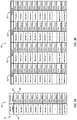
- the controller 20 may be configured with controller logic 28 corresponding to the sequence of operations 16 for control and monitoring of the automated system 10 of FIG. 1 using a scan cycle corresponding to the sequence of operations 16 and the controller logic 28.
- the sequence of operations 16 includes a listing of operations, including Operation 1 through Operation 10, a description of each operation, and a duration of each operation.
- the first operation, identified in the sequence of operations 16 as Operation 1 is described as "Advance Device 1 to Work Position," where the controller 20 provides an output to trigger the start of Operation 1 at start time T0.
- the timestamp of the start time T0 may be determined by the controller clock 24 and recorded by the controller 20 into a multi-array 40 (see FIGS.
- the multi-array 40 may be configured to receive automation data corresponding to the sequence of operations 16, as described in further detail herein.
- the multi-array 40 is stored in the controller memory 24, in a memory location in the controller memory 24 allocated to the multi-array 40.
- Operation 1 ends, e.g., when Device 1 is advanced from the Home Position (first state) and reaches the Work Position (second state), the sensor S2 is triggered and generates an output which is detected as input data by the controller 20 during execution of a scan cycle at a time T1, where time T1 is identified as the end time of Operation 1 and is measured by a timestamp determined by the controller clock 24 and corresponding to the time the controller 20 detects the input data from the sensor S2 signaling Device 1 in the Work Position.
- the controller 20 stores the timing data, e.g., the timestamp for end time T1 to a designated location in the multi-array 40 and controller memory 24.
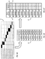
- FIG. 3A shows an example multi-array 40 including a data matrix 42.
- the data matrix 42 includes at least one member 44 and a plurality of data elements 46, 48 defined by the at least one member 44.
- the data elements 46, 48 may be configured in the controller 20 in a value-timestamp format or as a value-timestamp pair, although this designation and/or terminology is not intended to be limiting.
- each value of the respective data elements 46, 48 defining the value-timestamp pair may be configured as timing data, such that the data element pair 46, 48 defines a start and end time corresponding to the member 44 defining the data element pair 46, 48.
- the member 44 is defined by the automated system 10 and corresponds to at least one sensor 14 included in the automated system 10 and in communication with the controller 20.
- the member 44 may correspond to one or more sensors 14, or to one or more sensors 14 in communication with and/or configured to sense and/or monitor at least one of a device 12, an operation performed by the automated system 10, or a sub-system of the automated system 10, such as an assembly or manufacturing line, a machine including at least one device 12, a group of devices 12, etc.
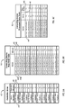
- FIGS. 4B-4C show a multi-array 40 configured for use in capturing automation data from the automated system 10 performing the sequence of operations 16 shown in FIG. 2 .
- the multi-array 40 consists of a single data matrix 42, where each member 44 of the multi-array 40 is associated with a respective operation of the sequence of operations 16 and each member 44 defines a first element 46 corresponding to the start time of the respective operation and defines a second element 48 corresponding to the end time of the respective operation.
- each member 44 of the multi-array 40 is associated with at least one sensor 14 of the automated system 10, where the associated sensor 14 provides input data to the controller 20 to determine the respective start and end times defining first and second elements 46, 48.
- the first member 44 of the multi-array 40 shown in FIG. 4C is associated with Operation 1 of the sequence of operations 16, is labeled "Device 1 Work Position" in the multi-array, and is defined by a start time T0 (first element 46) and an end time T1 (second element 48).
- the second member 44 of the multi-array 40 is associated with Operation 2 of the sequence of operations 16, is labeled "Device 2 Work Position” in the multi-array, and is defined by a start time T1' (first element 46) and an end time T2 (second element 48).
- the multi-array 40 is configured to include a member 44 corresponding to each of the ten operations Operation 1 through Operation 10, and a first and second element 46, 48 defined respectively by the start and end time of the respective operation.
- the controller 20 upon detecting the end of Operation 1 at end time T1, the controller 20, following the sequence of operations 16, triggers Operations 2 and 3 to start at the same start time T1' (see FIG. 4C ), such that Operations 2 and 3 may be considered concurrent operations and/or Devices 2 and 3 may be referred to as a group of devices.
- the start time T1' is measured by the controller clock 24 and recorded by the controller 20 in multi-array 40 in the respective start location time as the element value of the respective first data elements 46 defined by the respective members "Device 2 Work Position" associated with Operation 2 and "Device 3 Work Position" associated with Operation 3.
- sensor S4 When Operation 2 ends, e.g., when Device 2 is advanced to and reaches the Work Position, sensor S4 is triggered and generates an output which is detected as input data by the controller 20 during a scan cycle at an end time T2 determined by the controller clock 24.
- the end time T2 is measured by the controller clock 24 and recorded by the controller 20 in multi-array 40 in the end time location as the element value of the second data element 48 defined by the second member 44 labeled "Device 2 Work Position.”
- sensor S6 is triggered and generates an output which is detected at time T2' as input data by the controller 20.
- the end time T2' is measured by the controller clock 24 and recorded by the controller 20 in multi-array 40 in the end time location as the element value of the second data element 48 of the third member 44 labeled "Device 3 Work Position.”
- the controller 20, following the sequence of operations 16 triggers Operation 4 at a time T2" (see FIG. 4C ).
- the time T2" is measured by the controller clock 24 and recorded in the multi-array 40 in the start time location as the element value of the first data element 46 of the fourth member "Device 4 Work Position" associated with Operation 4.
- sensor S8 is triggered and generates an output which is detected as input data by the controller 20 during a scan cycle at an end time T3 determined by the controller clock 24.
- the end time T3 is measured by the controller clock 24 and recorded by the controller 20 in multi-array 40 in the end time location as the element value of the second data element 48 defined by the fourth member 44 labeled "Device 4 Work Position.”
- the controller 20 Upon detecting the completion of Operation 4 at time T3, the controller 20, following the sequence of operations 16, triggers Operation 5 at a time T3' (see FIG. 4C ).
- the time T3' is measured by the controller clock 24 and recorded in the multi-array 40 in the start time location as the element value of the first data element 46 of the fifth member "Device 5 Work Position" associated with Operation 5.
- sensor S10 When Operation 5 ends, e.g., when Device 5 is advanced to and reaches the Work Position, sensor S10 is triggered and generates an output which is detected as input data by the controller 20 during a scan cycle at an end time T4 determined by the controller clock 24.
- the end time T4 is measured by the controller clock 24 and recorded by the controller 20 in multi-array 40 in the end time location as the element value of the second data element 46 defined by the fifth member 44 labeled "Device 5 Work Position.”
- the controller 20 upon detecting the completion of Operation 5 at end time T4, triggers the start of Operation 6 "Return Device 1 to Home Position" at start time T4'.
- the start time T4' is measured by the controller clock 24 and recorded as the element value of the first element 46 defined by the sixth member 44 labeled "Return Device 1 to Home Position.”
- sensor S1 is triggered and generates an output which is detected as input data by the controller 20 during a scan cycle at an end time T5 determined by the controller clock 24, which is recorded in the multi-array 40 as the element value of the second element 48 of the sixth member 44 labeled "Return Device 1 to Home Position.”
- the process repeats in the same manner for the remaining operations Operation 7 through Operation 10 respectively associated with the seventh through tenth members of the multi-array 40, with the controller 20 continuing to execute the scan cycle at the scan frequency defined by the controller, wherein executing the scan cycle includes triggering each subsequent operation of the sequence of operations 16 using the logic 28 provided to the controller 20 upon detection of completion of the prior operation by the controller 20, recording a respective start time (T5', T5', T6", T7' as shown in FIG.
- the controller 20 may continue to execute the controller logic 28 and scan cycle such that the automated system 10 continues to repeat the sequence of operations 16, wherein each performance of the sequence of operations 16 by the automated system 10 may be referred to as an operational cycle of the automated system 10.
- the controller 20 updates the values of each of the elements 46, 48 in the multi-array 40 according to the scan frequency and the input data received by the controller 20 from the at least one sensor 14 associated with the respective element 46, 48 and stores the updated value of each element 46, 48 in the controller memory location corresponding to that element 46, 48.
- the scan rate may be 10 ms, e.g., the controller may have a scan time of 10 ms to complete one scan cycle, and the scan frequency may be equal to the scan rate such that the controller 20 monitors and/or updates each of the element values of the first and second elements 46, 48 in the multi-array 40 every 10 ms.
- the controller 20 may be configured to compare the element value stored in a controller memory location corresponding to the data element 46, 48 defining that element value, e.g., a prior element value of the respective data element 46, 48, to the current element value of the respective data element 46, 48 collected during a current scan cycle, to determine whether the current element value is changed from the prior element value.
- the prior element value remains stored in the controller memory location for the respective element 46, 48. If the current element value is changed from the prior element value, the element value stored in the controller memory location is updated by storing the current element value in the controller memory location for the respective element 46, 48.
- the computing device 30 may be configured to execute a data capture cycle which includes reading and collecting data stored in the multi-array 40 and storing the collected data to a first data table configured in the memory 36 of the computing device 30 to correspond to the multi-array 40, where the first data table may be configured, for example, as a raw data table 50 shown in FIG. 5B and corresponding to the multi-array 40 shown in FIG. 5A .
- the data capture rate of the computing device 30 may be of longer duration than the scan rate of the controller 20, and/or the data capture frequency defined by the computing device 30 may be less than the scan frequency of the controller 20 such that the element value of the each element 46, 48 in the multi-array 40 may change at least once between data capture cycles.
- the scan rate is 10 ms and equal to the scan frequency
- the data capture rate is 50 ms and equal to the data capture frequency
- the multi-array 40 may be used to capture automation data including timing data from the sensors 14 at different frequencies and time intervals.
- the multi-array 40 may be configured such that each sensor 14 or each operation of the sequence of operations 16 may be associated with a set of members 44 in the multi-array 40, to allow flexibility in the data capture method and to increase the number of operational cycles of the automated system 10 from which automation data including timing data may be collected.
- a set of members 44 may be associated with a set or pattern of scan cycles from which element values are recorded into the multi-array 40.
- a set of scan cycles may include five sequential scan cycles executed by the controller 20, where each scan cycle has a scan rate of 10 ms and the scan cycles are executed at a scan frequency equal to the scan rate, such that the set of five scan cycles is repeatedly executed by the controller 20 every 50 ms.
- the set of members 44 may include five members 44, where each of the five members 44 is each associated with the same sensor 14 or operation and with a different scan cycle of the set of scan cycles.
- the set of members 44 may be associated with an operation such as Operation 4 "Advance Device 4 to Work Position” and sensor S8 configured to sense when Device 4 is advanced to the work position.
- each of Members 4 through 8 may be associated with Operation 4 and a different scan cycle of the set of scan cycles such that Member 4 may include first and second elements 46, 48 corresponding to the start time T2" and end time T3 recorded during the first scan cycle of the set of five scan cycles, Member 5 may include first and second elements 46, 48 corresponding to the start time T2" and end time T3 recorded during the second scan cycle of the set of five scan cycles, Member 6 may include first and second elements 46, 48 corresponding to the start time T2" and end time T3 recorded during the third scan cycle of the set of five scan cycles, Member 7 may include first and second elements 46, 48 corresponding to the start time T2" and end time T3 recorded during the fourth scan cycle of the set of five scan cycles, and Member 8 may include
- a raw data table 50 may be configured to correspond with the multi-array 40 described in the present example, such that the raw data table 50, which may also be referred to herein as a first data table, would include locations corresponding to each of the data elements 46. 48 in the multi-array 40, e.g., would include locations to receive the element values of each of the data elements 46, 48 defined by each member 44, e.g., defined by each of Members 1 through Members N shown in FIGS. 3A and 6A , including each of Members 4 through 8 each associated with a different scan cycle of the set of five scan cycles of Operation 4 executed by the controller 20 between subsequent data capture cycles executed by the computing device 30.
- the multi-array 40 may be configured to include a plurality of data matrices 42, identified as Matrix 1 through Matrix 4, wherein each of the data matrices 42 is configured to collect automation data from the scan cycle executed by the controller 20 at a collection frequency defined by one or more predetermined time intervals or by a predetermined set or pattern of scan cycles executed by the controller 20.
- each of the data matrices 42 of the multi-array 40 shown in FIG. 3B may be configured as shown for the data matrix 42 of FIG.
- the controller 12 may be configured to define a collection frequency for the multi-array 40 such that automation data collected during a first scan cycle of a set of four scan cycles is stored in Matrix 1 of the multi-array 40 (see FIG. 3B ), automation data collected during a second scan cycle of the set of scan cycles is stored in Matrix 2, automation data collected during a third scan cycle of the set of scan cycles is stored in Matrix 3, and automation data collected by the controller 20 during a fourth scan cycle of the set of scan cycles is stored in Matrix 4.
- a first data table 50 configured by the computing device 30 to correspond to the multi-array 40 shown in FIG.
- each of the data matrices 42 of the multi-array 40 may be configured to collect data from scan cycles executed at defined intervals.
- Matrices 1, 2, and 3 may be configured to collect automation data from scan cycles at subsequent 10 ms intervals
- Matrix 4 may be configured to collect automation data from all scan cycles such that the automation data may be constantly updated in Matrix 4.
- the plurality of data matrices 42 included in the multi-array 40 may number more or less than the four data matrices 42 shown in the example provided herein to provide flexibility in data collection relative to scan rates, data capture rates, data storage configuration, communication network configuration, etc.
- Each of the matrices 42 of the multi-array 40 may be configured to include multiple members 44 corresponding to a sensor 14, as previously discussed.
- Each matrix 42 of the multi-array 40 may include a different set of members 44 and data elements defined thereby. For example, and referring again to the multi-array shown in FIG.
- Matrix 1 may include a first set of N1 members 44 which may differ from the second, third and fourth sets of N2, N3, N4 members 44 respectively included in Matrices 2, 3 and 4.
- the first set of N1 members included in Matrix 1 may correspond to the plurality of devices D1-D5 and sensors S1-S10 and sequence of operations 16 shown in FIGS.
- the second set of N2 members included in Matrix 2 may correspond to one or more sensors associated with a machine (not shown) included in the automated system 10
- the third set of N3 members included in Matrix 3 may correspond to one or more sensors associated with an assembly or manufacturing line (not shown) included in the automated system 10, wherein the data elements defined by each of the members of the three sets of members N1, N2, N3 define automation data associated with the respective automated operations performed by the automated system 10.
- the fourth set of N4 members included in Matrix 4 may correspond with a plurality of sensors 14 configured to sense the operating environment of the automated system 10, such that the data elements defined by each of the members of member set N4 may represent values other than timing data.
- Non-limiting examples of members and data elements defining values other than timing data may include sensors configured to monitor or sense environmental factors such as ambient temperature, air pressure or humidity, light intensity, machine temperatures, fluid temperature, pressure or flow, etc.
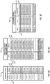
- FIGS. 5A-5C and 6A-6C shown is a multi-array 40 configured by the controller 20, a first or raw data table 50 configured by the computing device 30 to correspond to the multi-array 40, and a second or processed data table 52 configured by the computing device to receive data processed from the first data table 50 and associated with an operation or member of the automated system 10 such that the processed data may be saved to a database 38 and/or further analyzed by the computing device 30, for example, to determine a cycle time corresponding to an operation, device 12, or member 44 of the automated system 10.
- FIGS. 5B-5C illustrate configurations of first and second data tables 50, 52 corresponding to the multi-array 40 shown in FIGS. 5A and 4C defined by the example sequence of operations 16 shown in FIG. 2 .
- FIGS. 6B-6C illustrate configurations of the first and second data tables 50, 52 corresponding to the multi-array 40 including a single data matrix 42 shown in FIGS. 6A and 3A .
- FIGS. 5A-6C are non-limiting, and other configurations of the first and second data tables 50, 52 may be provided by the computing device 30 to correspond to a multi-array 40 configured by the controller 20.
- a first and second data table 50, 52 may be configured by the computing device 30 to correspond with the multi-array 40 shown in FIG. 3B , such that data element values defined by each respective data element 46,48 of each respective member 44 of each respective data matrix 42 of the multi-array 40 collected by the controller 20 has a corresponding location in the first data table 50 configured by the computing device 30, and such that the computing device 30 may configure a second data table 52 to receive data processed from the first data table 50 for association with its respective member 44 and storage in the database 38.
- the computing device 30 may be configured to execute a data capture cycle to collect element values from the multi-array 40 stored in the controller memory 26, and to write the captured data into a first data table 50 configured by the computing device 30 to correspond to the multi-array 40.
- the computing device 30 may include a data collector 34 configured to execute the data capture cycle at a data capture frequency, which may, but is not required to be, equivalent to a data capture rate defined by the data capture cycle.
- the data capture rate may be further defined and/or affected by the configuration of the computing device 30, the configuration of the communications network or method of communication through which the computing device 30 and the controller 20 are in communication with each other, etc.
- the multi-array 40 is configured by the controller 20 to include at least one member 44 and a plurality of elements 46, 48 defined by the at least one member 44.
- the multi-array 40 is configured such that a memory location is allocated in the controller memory 26 to store the multi-array 40, where the memory location storing the multi-array 40 may be referred to herein as the multi-array memory location.
- a respective controller memory location is defined for each of the respective elements 46, 48 defined by each respective member 44 of the multi-array 40.
- the size of the memory for each element 46, 48 may be a byte, a word, or more, as required to store the element value defined by the respective element.
- the first data table 50 is configured by the computing device 30 to correspond with the configuration of the multi-array 40 from which the computing device 30 will collect data using the data capture cycle.
- the first data table 50 also referred to as the raw data table, is configured to receive an element value for each respective element 46, 48 read by the computing device 30 from the multi-array 40 during a data capture cycle, such that the element value may be written by the computing device 30 into the raw data table 50 in a table location defined by the raw data table 50 and corresponding to the controller memory location for that respective element 46, 48.
- Configuring the raw data table 50 may include storing the respective controller memory location for each respective element 46, 48 in the computing device 30, such that each of the controller memory locations for each respective element 46, 48 is associated with a corresponding location in the first data table 50 to provide a plurality of corresponding locations defined by the first data table 50 and stored in the computing device memory 36.
- the first data table 50 may be configured differently from the multi-array 40, which may include, as shown in the referenced figures, providing more than one location 44A, 44B to identify the member 44 associated with each of the table locations allocated in the data table 50 as corresponding to the elements 46, 48.
- the computing device 30 reads the multi-array 40, e.g., reads the multi-array memory location allocated for the multi-array 40 in the controller memory 26, and writes the element values read from the controller memory locations of the multi-array memory location into the corresponding table locations of the raw data table 50
- data capture efficiencies can be realized using the multi-array 40 and table data structures described herein, as compared to reading and storing individual data points using a point to point data collection method.
- the computing device 30 may be configured to compare, during a current data capture cycle, the prior element value stored in a table location of the first data table 50 during a prior data capture cycle with the current element value stored in the corresponding controller memory location of each respective data element 46, 48, where the current element value is the element value read from the multi-array 40 during a current data capture cycle, to determine whether the current element value is changed from the prior element value. If no change has occurred, the prior element value remains stored in the first table location in the computing device memory 36 for the respective element 46, 48.
- the element value stored in the corresponding first table location in the computing device memory 36 is updated by storing the current element value in the first table location in the computing device memory 36 corresponding to the controller memory location for the changed respective element 46, 48.
- the computing device 30 may configure a second data table 52, which may be referred to herein as a processed data table 52, to convert the respective element value from the first data table 50 to the second data table 52 such that each of the respective element values read into the first data table 50 during the data capture cycle is associated in the second data table 52 with the member 44 defining the element 46, 48 corresponding to the respective element value.
- a processed data table 52 to convert the respective element value from the first data table 50 to the second data table 52 such that each of the respective element values read into the first data table 50 during the data capture cycle is associated in the second data table 52 with the member 44 defining the element 46, 48 corresponding to the respective element value.
- the controller 20 may determine element values respectively corresponding to the start time and end time T0, T1 for the operational cycle of Operation 1 scanned during the scan cycle, and store these element values to their respective controller memory locations allocated in the controller memory 26 for the first and second elements 46, 48.
- the computing device 30 reads the multi-array 40 and collects the element values of the start time and end time T0, T1 determined for the operational cycle of Operation 1 scanned by the controller 20 and stored in the multi-array memory location, and writes these element values to the raw data table 50.
- the raw data table 50 has been configured, for example, to provide a first table location associated with a name 44A shown as "Device 1.WorkPosition.0", where the first table location corresponds to the first element 46 defined by the member 44 "Device 1 Work Position.”
- the element value of the start time T0 read from the multi-array 40 is written to the first table location corresponding to the first element 46.
- a second table location is associated with a name 44B shown as "Device1.WorkPosition.1”, where the second table location corresponds to the second element 48 defined by the member 44 "Device 1 Work Position.”
- the element value of the end time T1 read from the multi-array 40 is written to the table location shown in FIG. 5B corresponding to the second element 48 defined by the member 44 "Device 1 Work Position.”
- the computing device 30 may process the first data table 50 to convert the element values for the start and end times T0, T1 stored in the first data table 50 to the second data table 52.
- the second data table includes the first member 44 named "Device1.WorkPosition" associated with the first and second elements 46, 48 defined by the member 44 respectively as the start time and end time T0, T1 of Operation 1 described as "Advance Device 1 to Work Position" in FIG. 2 , where the first member 44 corresponds to Operation 1.
- the element values, e.g., the timing data or timestamps, written into the first data table 50 for the start and end times T0, T1 of the operational cycle scanned to determine the start and end times T0, T1 for that operational cycle are converted by the computing device 30 and associated with the member "Device1.WorkPosition.”
- the second data table 52 including the element values of the start and end times T0, T1 for the scanned operational cycle may be stored in a database 38 using the computing device 30, and/or the element values of the start and end times T0, T1 determined for the scanned operational cycle may be associated, for example, with metadata identifying the associated member 44 and operational cycle from which the start and end times T0, T1 were determined.
- the computing device 30 may read the remaining element values of the remaining data elements T1' through T8 shown in the multi-array 40 of FIG. 5A from the multi-array 40, write these remaining element values into the first data table 50 shown in FIG. 5B , convert the remaining element values into the second data table 52 for association with the respective member 44 corresponding to each remaining element value, and store the converted element values such that they are associated with the respective member 44 corresponding to each element value and the operational cycle and/or scan cycle from which the stored element value was determined.
- the data capture cycle may be repeated such that element values associated with subsequent operational cycles of the sequence of operations 16 performed by the automated system 10 and/or determined by subsequent scan cycles executed by the controller 10 may be converted for association with the respective member defining the element 46, 48 and element value, and stored to provide a history of element values for that element 46, 48.
- the computing device 30 may be configured to analyze the element values, which may include analyzing the start time and end time values of a member 44 for an operational cycle or scan cycle to determine a cycle time for the member 44.
- a cycle time of Operation 1 may be calculated by determining the difference between the element value (timing data or time stamp) of the start time T0 and the element value (timing data or time stamp) of the end time T1, wherein each of these values is determined using the controller clock 24 and input data received by the controller 20 during execution of a scan cycle and/or performance of an operational cycle of the sequence of operations 16.
- the cycle time and/or related timing data for that operational/scan cycle may be stored in the database 38, as described previously, as a prior operational/scan cycle.
- the data capture cycle may be repeated according to the data capture frequency to convert and store timing data from a plurality of prior operational cycles to provide historical cycle time and timing data stored to the database 38.
- Cycle time and/or related timing data for a current operational cycle may be determined for analysis and/or comparison with the historical data by the computing device 30.
- At least one of the devices 12 may be dissimilar from the other devices 12, and at least one of the sensors 14 may be dissimilar from the other sensors 14.
- the automated system 10 may be arranged such that a single sensor 14 may be configured and used to sense the first state and the second state of an associated device 12 and to output a signal corresponding to the sensed one of the first and second state.
- a single sensor 14 may be configured to sense a designated state of a group of devices 12, and to output a signal corresponding a sensed state of the group of devices 12.
- the sensed state of the group of devices 12 triggering an output from the sensor 14 may correspond to the sensor 14 sensing a first device 12 of the group of devices 12 reaching the designated state.
- the sensed state of the group of devices 12 triggering an output from the sensor 14 may correspond to the sensor 14 sensing the last device 12 of the group of devices 12 reaching the designated state, e.g., sensing that all devices of the group of devices 12 have reached the designated state.
Landscapes
- Physics & Mathematics (AREA)
- General Physics & Mathematics (AREA)
- Engineering & Computer Science (AREA)
- Automation & Control Theory (AREA)
- Programmable Controllers (AREA)
- Arrangements For Transmission Of Measured Signals (AREA)
- Testing And Monitoring For Control Systems (AREA)
- Testing Of Engines (AREA)
- Selective Calling Equipment (AREA)
Claims (23)
- Verfahren zur Erfassung von Automatisierungsdaten, umfassend:Ausführen eines Abtastzyklus unter Verwendung eines Controllers (20), welcher als ein Automatisierungscontroller ausgebildet ist;Sammeln von Eingabedaten während des Abtastzyklus von wenigstens einem Sensor (14) in Kommunikation mit dem Controller (20), wobei der wenigstens eine Sensor (14) wenigstens einem Mitglied entspricht, wobei das wenigstens eine Mitglied durch eine Vielzahl von Elementen definiert wird und jedes jeweilige Element der Vielzahl von Elementen einen jeweiligen Elementwert aufweist, der durch die Eingabedaten bestimmt ist;Bestimmen jedes jeweiligen Elementwerts für den Abtastzyklus unter Verwendung der Eingabedaten, die während des Abtastzyklus gesammelt worden sind;Konfigurieren eines Multi-Arrays (40) unter Verwendung des Controllers (20), wobei das Multi-Array (40) das wenigstens eine Mitglied und die Vielzahl von Elementen umfasst, die durch das wenigstens eine Mitglied definiert werden, wobei das Konfigurieren des Multi-Arrays (40) das Allokieren einer Multi-Array-Speicherstelle umfasst, um das Multi-Array (40) in dem Controller (20) zu speichern, wobei die Multi-Array-Speicherstelle eine jeweilige Controller-Speicherstelle für jedes jeweilige Element der Vielzahl von Elementen umfasst, die durch das wenigstens eine Mitglied definiert wird;Speichern des Elementwerts von jedem jeweiligen Element für den Abtastzyklus in der jeweiligen Controller-Speicherstelle in dem Multi-Array (40), wobei der Controller (20) eine Controller-Uhr (24) umfasst, wobei der Abtastzyklus durch eine Sequenz von Operationen (16) definiert wird;dadurch gekennzeichnet, dassdas wenigstens eine Mitglied einer Operation der Sequenz von Operationen (16) entspricht;die Vielzahl von Elementen, welche durch das wenigstens eine Mitglied definiert wird, umfasst ein erstes Element und ein zweites Element;das erste Element durch den Start der Operation definiert wird;das zweite Element durch das Ende der Operation definiert wird;der Elementwert des ersten Elements durch die Startzeit der Operation definiert wird, welche durch die Controller-Uhr (24) bestimmt wird; undder Elementwert des zweiten Elements durch die Endzeit der Operation definiert wird, welche durch die Controller-Uhr (24) bestimmt wird.
- Verfahren nach Anspruch 1, ferner umfassend:Ausführen des Abtastzyklus mehrere Male unter Verwendung des Controllers (20), um eine Vielzahl von Abtastzyklen, einschließlich eines momentanen Abtastzyklus und eines vorhergehenden Abtastzyklus, bereitzustellen, wobei der vorhergehende Abtastzyklus dem momentanen Abtastzyklus vorhergeht;Bestimmen des jeweiligen Elementwerts für jeden jeweiligen Abtastzyklus der Vielzahl von Abtastzyklen unter Verwendung der Eingabedaten, die während des jeweiligen Abtastzyklus gesammelt worden sind;für jedes jeweilige Element der Vielzahl von Elementen, Vergleichen eines momentanen Elementwerts des jeweiligen Elements, der für den momentanen Abtastzyklus bestimmt worden ist, mit einem vorhergehenden Elementwert des jeweiligen Elements, der für den vorhergehenden Abtastzyklus bestimmt worden ist, um zu bestimmen, ob der momentane Elementwert sich gegenüber dem vorhergehenden Elementwert geändert hat; undSpeichern des momentanen Elementwerts von jedem jeweiligen Element, falls sich der momentane Elementwert gegenüber dem vorhergehenden Elementwert geändert hat.
- Verfahren nach Anspruch 1, wobei der wenigstens eine Sensor (14) eine Vielzahl von Sensoren (14) umfasst, wobei das Sammeln der Eingabedaten während des Abtastzyklus das Sammeln von Eingabedaten von der Vielzahl von Sensoren (14) umfasst, wobei das wenigstens eine Mitglied der Vielzahl von Sensoren (14) entspricht und wobei das Bestimmen von jedem jeweiligen Elementwert für den wenigstens einen Wert für den Abtastzyklus das Verwenden von Eingabedaten umfasst, die während des jeweiligen Abtastzyklus von der Vielzahl von Sensoren (14) gesammelt worden sind.
- Verfahren nach Anspruch 1, wobei der wenigstens eine Sensor (14) ein Sensor (14) ist, welcher ausgebildet ist, Eingabedaten bereitzustellen, einschließlich einer ersten Eingabe und einer zweiten Eingabe, die sich von der ersten Eingabe unterscheidet, wobei das wenigstens eine Mitglied umfasst: ein erstes Mitglied, das dem Sensor (14) entspricht und durch eine erste Vielzahl von Elementen definiert wird, wobei jedes einen jeweiligen Elementwert aufweist, der durch die erste Eingabe bestimmt ist; und ein wenigstens zweites Element, das dem Sensor (14) entspricht und durch eine wenigstens zweite Vielzahl von Elementen definiert wird, wobei jedes einen jeweiligen Elementwert aufweist, der durch die wenigstens zweite Eingabe bestimmt ist, wobei das Multi-Array (40) das erste Mitglied, das wenigstens zweite Mitglied, die erste Vielzahl von Elementen und die wenigstens zweite Vielzahl von Elementen umfasst, wobei die Multi-Array-Speicherstelle eine jeweilige Controller-Speicherstelle für jedes jeweilige Element der ersten und wenigstens zweiten Vielzahl von Elementen umfasst; und wobei das Verfahren ferner das Speichern des jeweiligen Elementwerts von jedem jeweiligen Element der ersten und wenigstens zweiten Vielzahl von Elementen für den Abtastzyklus in der jeweiligen Controller-Speicherstelle von jedem jeweiligen Element der ersten und wenigstens zweiten Vielzahl von Elementen in dem Multi-Array (40) umfasst.
- Verfahren nach Anspruch 1, wobei das wenigstens eine Mitglied durch den wenigstens einen Sensor (14) in Kommunikation mit einer Vorrichtung (12) definiert wird und jedes der Vielzahl von Elementen durch einen Status der Vorrichtung (12) bestimmt ist.
- Verfahren nach Anspruch 1, wobei das wenigstens eine Mitglied durch eine Gruppe von Vorrichtungen (12) definiert wird, wobei der wenigstens eine Sensor (14) in Kommunikation mit der Gruppe von Vorrichtungen (12) ist und wobei das erste Element durch einen ersten Status der Gruppe von Vorrichtungen (12) bestimmt ist und das zweite Element durch einen zweiten Status der Gruppe von Vorrichtungen (12) bestimmt ist.
- Verfahren nach Anspruch 1, ferner umfassend:Ausführen einer Vielzahl von Abtastzyklen unter Verwendung des Controllers (20), wobei das Ausführen der Vielzahl von Abtastzyklen das Ausführen eines sich wiederholenden Satzes von Abtastzyklen umfasst, wobei das wenigstens eine Mitglied einen Satz von Mitgliedern umfasst, wobei das Multi-Array (40) den Satz von Mitgliedern umfasst, wobei jedes jeweilige Mitglied des Satzes von Mitgliedern mit einem jeweiligen Abtastzyklus des sich wiederholenden Satzes von Abtastzyklen verknüpft ist, und wobei das Bestimmen von jedem jeweiligen Elementwert für jedes jeweilige Mitglied des Satzes von Mitgliedern das Verwenden von Eingabedaten umfasst, die während des jeweiligen Abtastzyklus des sich wiederholenden Satzes von Abtastzyklen gesammelt worden sind.
- Verfahren nach Anspruch 1, wobei das Verfahren ferner das Ausführen einer Vielzahl von Abtastzyklen unter Verwendung des Controllers (20) umfasst, wobei das Multi-Array (40) eine erste Datenmatrix und wenigstens eine zweite Datenmatrix umfasst, wobei das wenigstens eine Mitglied wenigstens ein erstes Matrixmitglied und wenigstens ein zweites Matrixmitglied umfasst, wobei die erste Datenmatrix das wenigstens eine erste Matrixmitglied und die Vielzahl von Elementen umfasst, welche durch das wenigstens eine erste Matrixmitglied definiert werden; wobei die zweite Datenmatrix das wenigstens eine zweite Matrixmitglied und die Vielzahl von Elementen umfasst, die durch das wenigstens eine zweite Matrixmitglied definiert werden, wobei die Multi-Array-Speicherstelle ausgebildet ist, eine jeweilige Controller-Speicherstelle für jedes jeweilige Element der Vielzahl von Elementen zu umfassen, die durch das wenigstens eine erste Matrixmitglied und das wenigstens eine zweite Matrixmitglied definiert werden; Definieren einer Sammelfrequenz für die erste Datenmatrix und die wenigstens zweite Datenmatrix; Speichern des Elementwerts von jedem jeweiligen Element für die Vielzahl von Abtastzyklen in der jeweiligen Controller-Speicherstelle in der ersten Datenmatrix und der wenigstens zweiten Datenmatrix gemäß der Sammelfrequenz.
- Verfahren nach Anspruch 8, wobei das wenigstens eine erste Matrixmitglied und das wenigstens eine zweite Matrixmitglied als dasselbe Mitglied ausgebildet sind.
- Verfahren nach Anspruch 8, wobei der Abtastzyklus durch eine Abtastrate charakterisiert ist und die Sammelfrequenz relativ zu der Abtastrate definiert ist.
- Verfahren nach Anspruch 1, ferner umfassend:Bereitstellen einer Berechnungsvorrichtung (30) in Kommunikation mit dem Controller (20);Konfigurieren einer ersten Datentabelle (50) unter Verwendung der Berechnungsvorrichtung (30);wobei das Konfigurieren der ersten Datentabelle (50) das Speichern der jeweiligen Controller-Speicherstelle für jedes eines jeweiligen Elements in der Berechnungsvorrichtung (30), so dass jede der Controller-Speicherstellen für jedes jeweilige Element mit einer entsprechenden Stelle in der ersten Datentabelle (50) verknüpft ist, um eine Vielzahl von entsprechenden Stellen bereitzustellen;Ausführen eines Datenerfassungszyklus unter Verwendung der Berechnungsvorrichtung (30);Auslesen der Multi-Array-Speicherstelle des Controllers (20) während des Datenerfassungszyklus unter Verwendung der Berechnungsvorrichtung (30);Schreiben jedes jeweiligen Elementwerts, der aus der Multi-Array-Speicherstelle des Controllers (20) ausgelesen wird, an die entsprechende Stelle der ersten Datentabelle (50).
- Verfahren nach Anspruch 11, wobei der Abtastzyklus durch eine Abtastrate charakterisiert ist und der Erfassungszyklus durch eine Erfassungsrate charakterisiert ist, die eine längere Dauer als die Abtastrate aufweist.
- Verfahren nach Anspruch 11, wobei das Auslesen der Multi-Array-Speicherstelle des Controllers (20) das Auslesen jeder jeweilige Controller-Speicherstelle der Multi-Array-Speicherstelle umfasst.
- Verfahren nach Anspruch 13, ferner umfassend:Ausführen des Datenerfassungszyklus zu mehreren Zeiten unter Verwendung der Berechnungsvorrichtung (30), um eine Vielzahl von Datenerfassungszyklen bereitzustellen, einschließlich eines momentanen Datenerfassungszyklus und eines vorhergehenden Datenerfassungszyklus, wobei der vorhergehende Datenerfassungszyklus dem momentanen Datenerfassungszyklus vorangeht;für jede jeweilige Controller-Speicherstelle in dem Multi-Array (40), Vergleichen eines momentanen Elementwerts, der während des momentanen Datenerfassungszyklus aus jeder jeweiligen Controller-Speicherstelle ausgelesen worden ist, mit einem vorhergehenden Elementwert, der an einer entsprechenden Stelle in der ersten Datentabelle (50) gespeichert ist, um zu bestimmen, ob sich der momentane Elementwert gegenüber dem vorhergehenden Elementwert geändert hat; undSpeichern des momentanen Elementwerts von jedem jeweiligen Element, das von der jeweiligen Controller-Speicherstelle an der jeweiligen entsprechenden Stelle der ersten Datentabelle (50) ausgelesen worden ist, falls sich der momentane Elementwert gegenüber dem vorhergehenden Elementwert geändert hat.
- Verfahren nach Anspruch 11, ferner umfassend:Konfigurieren einer zweiten Datentabelle (50) unter Verwendung der Berechnungsvorrichtung (30);wobei die zweite Datentabelle (50) ausgebildet ist, die jeweiligen Elementwerte der Vielzahl von Elementen, die in die Vielzahl von jeweiligen Stellen der ersten Datentabelle (50) geschrieben sind, in die zweite Tabelle zu schreiben, so dass das wenigstens eine Mitglied mit den jeweiligen Elementwerten der Vielzahl von Elementen verknüpft ist, die durch das wenigstens eine Mitglied definiert sind;wobei das Ausführen des Datenerfassungszyklus unter Verwendung der Berechnungsvorrichtung (30) ferner das Konvertieren der Elementwerte, welche in die erste Datentabelle (50) geschrieben sind, in die zweite Datentabelle (50) umfasst; Speichern der zweiten Datentabelle (50) in einer Datenbank (38) unter Verwendung der Berechnungsvorrichtung (30); wobei die jeweiligen Elementwerte der Vielzahl von Elementen, welche durch das wenigstens eine Mitglied definiert werden, mit dem wenigstens einen Mitglied in der Datenbank (38) verknüpft sind.
- Verfahren nach Anspruch 15, ferner umfassend:Ausführen des Datenerfassungszyklus zu mehreren Zeiten unter Verwendung der Berechnungsvorrichtung (30), um eine Vielzahl von Datenerfassungszyklen bereitzustellen; undwobei das Speichern der zweiten Datentabelle (50) in einer Datenbank (38) unter Verwendung der Berechnungsvorrichtung (30) das Speichern der jeweiligen Elementwerte der Vielzahl von Elementen von der Vielzahl von Datenerfassungszyklen umfasst, so dass die jeweiligen Elementwerte, die mit dem wenigstens einen Element von einem der Vielzahl von Datenerfassungszyklen verknüpft sind, mit den jeweiligen Elementwerten verglichen werden können, die mit dem wenigstens einen Mitglied von einem anderen der Vielzahl von Datenerfassungszyklen verknüpft sind.
- Verfahren nach Anspruch 16, wobei:der Controller (20) eine Controller-Uhr (24) umfasst;die Vielzahl von Elementen, die durch das wenigstens eine Mitglied definiert werden, ein erstes Element und ein zweites Element umfassen;das erste Element durch einen Startstatus des Mitglieds definiert wird;das zweite Element durch einen Endstatus des Mitglieds definiert wird;der Elementwert des ersten Elements eine Startzeit ist, die durch den Zeitpunkt der Startbedingung definiert wird, bestimmt durch die Eingabedaten, und durch die Controller-Uhr (24) gemessen wird;der Elementwert des zweiten Elements eine Endzeit ist, die durch den Zeitpunkt der Endbedingung definiert wird, bestimmt durch die Eingabedaten, und durch die Controller-Uhr (24) gemessen wird; undeine Zykluszeit für das Mitglied durch die Startzeit und die Endzeit definiert wird;wobei das Verfahren ferner umfasst:Bestimmen einer ersten Zykluszeit für das wenigstens eine Mitglied unter Verwendung der Berechnungsvorrichtung (30<9, wobei die erste Zykluszeit durch die jeweiligen ersten und zweiten Elementwerte definiert ist, die mit dem wenigstens einen Mitglied von einem der Vielzahl von Datenerfassungszyklen verknüpft ist.
- Verfahren nach Anspruch 17, wobei das Verfahren ferner umfasst:Bestimmen einer zweiten Zykluszeit für das wenigstens eine Mitglied unter Verwendung der Berechnungsvorrichtung (30);wobei die zweite Zykluszeit durch die jeweiligen ersten und zweiten Elementwerte definiert ist, die mit dem wenigstens einen Mitglied von einem weiteren der Vielzahl von Datenerfassungszyklen verknüpft ist; undVergleichen der ersten Zykluszeit und der zweiten Zykluszeit unter Verwendung der Berechnungsvorrichtung (30).
- System mit:einem Controller (20), einschließlich einer Controller-Uhr (24);wobei der Controller (20) als ein Automatisierungscontroller ausgebildet ist;einer Vielzahl von Sensoren (14) in Kommunikation mit dem Controller (20);einer Berechnungsvorrichtung (30) in Kommunikation mit dem Controller (20);wobei der Controller (20) programmiert ist zum:Ausführen eines Abtastzyklus mit einer Abtastfrequenz, wobei der Abtastzyklus durch eine Sequenz von Operation (16) definiert wird, einschließlich wenigstens einer Operation;Sammeln von Eingabedaten während des Abtastzyklus von der Vielzahl von Sensoren (14), wobei die wenigstens eine Operation wenigstens einem Sensor (14) der Vielzahl von Sensoren (14) entspricht;Konfigurieren eines Multi-Arrays (40), das wenigstens ein Mitglied umfasst sowie ein erstes Element und ein zweites Element, welche durch das wenigstens eine Mitglied definiert werden. wobei das wenigstens eine Mitglied der wenigstens einen Operation entspricht, das erste Element einen ersten Elementwert aufweist, der einer Startzeit der wenigstens einen Operation entspricht und durch die Eingabedaten definiert ist, das zweite Element einen zweiten Elementwert aufweist, der einer Endzeit der wenigstens einen Operation entspricht und durch die Eingabedaten definiert ist, der erste und der zweite Elementwert während des Abtastzyklus durch die Eingabedaten und die Controller-Uhr (24) bestimmt wird;wobei das Konfigurieren des Multi-Arrays (40) umfasst: Allokieren einer Multi-Array-Speicherstelle in dem Controller (20), wobei die Multi-Array-Speicherstelle eine jeweilige Controller-Speicherstelle für das erste Element und das zweite Element umfasst, welche durch das wenigstens eine Mitglied definiert werden; Bestimmen des ersten und zweiten Elementwerts während des Abtastzyklus unter Verwendung des Controllers (20); Speichern des Elementwerts von jedem jeweiligen Element, welches durch das wenigstens eine Mitglied definiert wird, für den Abtastzyklus in der jeweiligen Controller-Speicherstelle in dem Multi-Array (40);wobei die Berechnungsvorrichtung (30) programmiert ist zum: Konfigurieren einer ersten Datentabelle (50) unter Verwendung der Berechnungsvorrichtung (30), wobei das Konfigurieren der ersten Datentabelle (50) das Speichern der jeweiligen Controller-Speicherstelle für jedes jeweilige Element in der Berechnungsvorrichtung (30) umfasst, so dass jede der Controller-Speicherstellen für jedes jeweilige Element mit einer entsprechenden Stelle in der ersten Datentabelle (50) verknüpft ist, um eine Vielzahl von entsprechenden Stellen bereitzustellen; Ausführen eines Datenerfassungszyklus mit einer Datenerfassungsfrequenz; Auslesen der Multi-Array-Speicherstelle des Controllers (20) während des Datenerfassungszyklus; und Schreiben jedes jeweiligen Elementwerts, der aus der Multi-Array-Speicherstelle des Controllers (20) ausgelesen wird, an der entsprechenden Stelle der ersten Datentabelle (50).
- System nach Anspruch 19, wobei:das erste Element ein Wert ist;das zweite Element ein Zeitstempel ist, der mit dem Wert verknüpft ist;das erste und zweite Element in dem Multi-Array (40) als ein Wert-Zeitstempel-Paar gespeichert sind.
- System nach Anspruch 19, ferner umfassend:den wenigstens einen Sensor (14) in Kommunikation mit wenigstens zwei Vorrichtungen (12);die Sequenz von Operationen (16) umfasst wenigstens zwei gleichzeitige Operationen;wobei eine jeweilige Vorrichtung (12) der wenigstens zwei Vorrichtungen (12) jede jeweilige Operation der wenigstens zwei gleichzeitigen Operationen durchführt;wobei das wenigstens eine Mitglied wenigstens zwei Mitglieder umfasst, die den wenigstens zwei Vorrichtungen (12) entsprechen;wobei jedes jeweilige Mitglied der wenigstens zwei Mitglieder ein erstes Element und ein zweites Element definiert;wobei das erste Element der wenigstens zwei Mitglieder einen ersten Elementwert aufweist, der einer Startzeit der wenigstens zwei gleichzeitigen Operationen entspricht, welche durch die Eingabedaten definiert ist und dieselbe Startzeit für jedes der wenigstens zwei Mitglieder ist;wobei das zweite Element von jedem jeweiligen Mitglied der wenigstens zwei Mitglieder einen zweiten Elementwert aufweist, der durch die Eingabedaten definiert ist und einer jeweiligen Endzeit der jeweiligen der wenigstens zwei gleichzeitigen Operation entspricht, welche von dem jeweiligen Mitglied durchgeführt wird.
- System nach Anspruch 19, ferner umfassend:die Berechnungsvorrichtung (30), einschließlich einer Datenbank (38), wobei die Berechnungsvorrichtung (30) ferner programmiert ist zum:Konfigurieren einer zweiten Datentabelle (50), wobei die zweite Datentabelle (50) ausgebildet ist, die Vielzahl von entsprechenden Stellen der ersten Datentabelle (50) in die zweite Tabelle zu konvertieren, so dass das wenigstens eine Mitglied mit dem ersten und zweiten Element verknüpft ist, welche durch das wenigstens eine Mitglied definiert sind; Ausführen des Datenerfassungszyklus, einschließlich des Konvertierens der Elementwerte, die in die erste Datentabelle (50) geschrieben sind, in die zweite Datentabelle (50); und Speichern der zweiten Datentabelle (50) in der Datenbank (38), wobei die jeweiligen Elementwerte der Vielzahl von Elementen, welche durch das wenigstens eine Mitglied definiert sind, mit dem wenigstens einen Mitglied in der Datenbank (38) verknüpft sind.
- System nach Anspruch 19, ferner umfassend:die Berechnungsvorrichtung (30), welche programmiert ist, eine Zykluszeit für die Operation zu bestimmen, die dem wenigstens einen Mitglied entspricht, wobei die Zykluszeit durch den ersten und zweiten Elementwert definiert wird, die mit dem wenigstens einen Mitglied in der Datenbank (38) verknüpft sind.
Priority Applications (1)
| Application Number | Priority Date | Filing Date | Title |
|---|---|---|---|
| EP17170782.1A EP3223096B1 (de) | 2011-12-06 | 2012-12-05 | Verfahren und system zur erfassung von automatisierungsdaten |
Applications Claiming Priority (3)
| Application Number | Priority Date | Filing Date | Title |
|---|---|---|---|
| US201161567208P | 2011-12-06 | 2011-12-06 | |
| US13/693,758 US9778652B2 (en) | 2011-12-06 | 2012-12-04 | Method and system for capturing automation data |
| PCT/US2012/067883 WO2013085959A2 (en) | 2011-12-06 | 2012-12-05 | Method and system for capturing automation data |
Related Child Applications (1)
| Application Number | Title | Priority Date | Filing Date |
|---|---|---|---|
| EP17170782.1A Division EP3223096B1 (de) | 2011-12-06 | 2012-12-05 | Verfahren und system zur erfassung von automatisierungsdaten |
Publications (2)
| Publication Number | Publication Date |
|---|---|
| EP2788829A2 EP2788829A2 (de) | 2014-10-15 |
| EP2788829B1 true EP2788829B1 (de) | 2017-05-17 |
Family
ID=48524560
Family Applications (2)
| Application Number | Title | Priority Date | Filing Date |
|---|---|---|---|
| EP12806762.6A Active EP2788829B1 (de) | 2011-12-06 | 2012-12-05 | Verfahren und system zur erfassung von automatisierungsdaten |
| EP17170782.1A Active EP3223096B1 (de) | 2011-12-06 | 2012-12-05 | Verfahren und system zur erfassung von automatisierungsdaten |
Family Applications After (1)
| Application Number | Title | Priority Date | Filing Date |
|---|---|---|---|
| EP17170782.1A Active EP3223096B1 (de) | 2011-12-06 | 2012-12-05 | Verfahren und system zur erfassung von automatisierungsdaten |
Country Status (6)
| Country | Link |
|---|---|
| US (2) | US9778652B2 (de) |
| EP (2) | EP2788829B1 (de) |
| JP (1) | JP6204372B2 (de) |
| KR (2) | KR102133855B1 (de) |
| CN (2) | CN104040448B (de) |
| WO (1) | WO2013085959A2 (de) |
Families Citing this family (17)
| Publication number | Priority date | Publication date | Assignee | Title |
|---|---|---|---|---|
| US10048670B2 (en) * | 2014-05-08 | 2018-08-14 | Beet, Llc | Automation operating and management system |
| US20170160714A1 (en) * | 2014-07-03 | 2017-06-08 | General Electric Company | Acquisition of high frequency data in transient detection |
| KR101593834B1 (ko) * | 2014-10-30 | 2016-02-12 | 엘에스산전 주식회사 | Plc 시스템 |
| US10984338B2 (en) | 2015-05-28 | 2021-04-20 | Raytheon Technologies Corporation | Dynamically updated predictive modeling to predict operational outcomes of interest |
| JP6520545B2 (ja) * | 2015-08-10 | 2019-05-29 | オムロン株式会社 | サポート装置およびサポートプログラム |
| CN107924186B (zh) * | 2015-08-24 | 2021-03-09 | 比特股份有限公司 | 生成机器心跳的方法 |
| KR101758558B1 (ko) * | 2016-03-29 | 2017-07-26 | 엘에스산전 주식회사 | 에너지 관리 서버 및 그를 갖는 에너지 관리 시스템 |
| US10996642B2 (en) * | 2017-08-29 | 2021-05-04 | Siemens Aktiengesellschaft | Method and apparatus for determining data reading cycle |
| US10802457B2 (en) * | 2017-10-23 | 2020-10-13 | Schneider Electric USA, Inc. | Centralized motor thermal memory management |
| US11468216B2 (en) | 2018-08-28 | 2022-10-11 | Linecraft Ai Limited | Method for building a model of a physical system |
| CN109947868A (zh) * | 2019-03-22 | 2019-06-28 | 晶晨半导体(上海)股份有限公司 | 一种存储系统的信号显示方法 |
| CN110135678A (zh) * | 2019-03-29 | 2019-08-16 | 广州明珞汽车装备有限公司 | 一种基于工位的工艺时序分析方法、系统及存储介质 |
| CN110245374B (zh) * | 2019-04-26 | 2023-06-16 | 广州明珞汽车装备有限公司 | 一种工艺时序间隔分析方法、系统、装置和存储介质 |
| JP7359601B2 (ja) * | 2019-09-03 | 2023-10-11 | 株式会社日立製作所 | データ抽出装置、データ抽出方法、およびデータ抽出プログラム |
| CN111681261B (zh) * | 2020-04-22 | 2022-12-13 | 广州明珞汽车装备有限公司 | 一种基于动作定位的甘特图处理方法、系统和存储介质 |
| US11435715B2 (en) * | 2020-05-14 | 2022-09-06 | Hitachi, Ltd. | System and method for detecting change over in manufacturing field |
| CN115495498B (zh) * | 2022-09-23 | 2023-06-16 | 共青科技职业学院 | 数据关联方法、系统、电子设备及存储介质 |
Family Cites Families (40)
| Publication number | Priority date | Publication date | Assignee | Title |
|---|---|---|---|---|
| US4553224A (en) | 1983-08-04 | 1985-11-12 | Allen-Bradley Company | Multiplexed data handler for programmable controller |
| JPH01236306A (ja) | 1988-03-17 | 1989-09-21 | Nissan Motor Co Ltd | シーケンス制御装置 |
| US5097470A (en) * | 1990-02-13 | 1992-03-17 | Total Control Products, Inc. | Diagnostic system for programmable controller with serial data link |
| US5285376A (en) * | 1991-10-24 | 1994-02-08 | Allen-Bradley Company, Inc. | Fuzzy logic ladder diagram program for a machine or process controller |
| US5991371A (en) * | 1993-12-07 | 1999-11-23 | Brother Kogyo Kabushiki Kaisha | Communication apparatus |
| GB2292620B (en) * | 1994-08-16 | 1998-04-22 | Motorola Israel Ltd | Event driven programmer logic controller processor arrangement |
| JP3447432B2 (ja) * | 1995-06-07 | 2003-09-16 | 三菱電機株式会社 | ネットワークデータサーバ装置およびプログラマブルロジックコントローラシステム |
| US6327511B1 (en) * | 1998-12-30 | 2001-12-04 | Schneider Automation, Inc. | Input/output (I/O) scanner for a control system with peer determination |
| US6499114B1 (en) * | 1999-02-17 | 2002-12-24 | General Electric Company | Remote diagnostic system and method collecting sensor data according to two storage techniques |
| SG74705A1 (en) * | 1999-03-12 | 2001-06-19 | Sony Electronics Singapore Pte | A monitoring system for monitoring processing equipment |
| US6993456B2 (en) * | 1999-09-30 | 2006-01-31 | Rockwell Automation Technologies, Inc. | Mechanical-electrical template based method and apparatus |
| GB0004194D0 (en) * | 2000-02-22 | 2000-04-12 | Nat Power Plc | System and method for monitoring a control process in a process plant |
| US7603289B2 (en) | 2001-07-13 | 2009-10-13 | Siemens Aktiengesellschaft | System and method for electronic delivery of content for industrial automation systems |
| US7027954B2 (en) * | 2001-12-21 | 2006-04-11 | Honeywell International Inc. | Method and apparatus for retrieving activity data related to an activity |
| TWI243339B (en) * | 2002-03-19 | 2005-11-11 | Casio Computer Co Ltd | Image reading apparatus and drive control method |
| ATE344956T1 (de) | 2002-03-21 | 2006-11-15 | United Parcel Service Inc | System zur erfassung und speicherung von fahrzeugsensordaten |
| US7117043B1 (en) * | 2002-03-28 | 2006-10-03 | Integrator.Com | Method for programming a programmable logic controller |
| JP4161189B2 (ja) * | 2002-12-27 | 2008-10-08 | オムロン株式会社 | 情報監視支援装置及び情報監視システム |
| US6862486B2 (en) * | 2003-03-04 | 2005-03-01 | Activplant Corporation | System and method for processing data relating to conditions in a manufacturing process |
| US7775245B2 (en) * | 2005-04-08 | 2010-08-17 | Air Products And Chemicals, Inc. | Secure loop system and method for supply and delivery of product contained in a carrier |
| JP2007213451A (ja) | 2006-02-10 | 2007-08-23 | Omron Corp | 収集データのモニタ方法及び装置 |
| CN101467184B (zh) * | 2006-04-13 | 2013-03-13 | Igt公司 | 用于在游戏设备上集成远程主机和本地显示内容的方法和装置 |
| RU2431157C2 (ru) * | 2006-06-15 | 2011-10-10 | Конинклейке Филипс Электроникс, Н.В. | Интегрированный многоканальный преобразователь временных интервалов в код для времяпролетной позитронно-эмиссионной томографии |
| US7853431B2 (en) * | 2006-09-29 | 2010-12-14 | Fisher-Rosemount Systems, Inc. | On-line monitoring and diagnostics of a process using multivariate statistical analysis |
| US7853568B2 (en) * | 2007-03-01 | 2010-12-14 | Air Liquide Large Industries U.S. Lp | High speed data historian |
| US7941229B2 (en) * | 2007-06-06 | 2011-05-10 | Rockwell Automation Technologies, Inc. | High-speed sequential sampling of I/O data for industrial control |
| US7930639B2 (en) * | 2007-09-26 | 2011-04-19 | Rockwell Automation Technologies, Inc. | Contextualization for historians in industrial systems |
| US7657333B2 (en) * | 2007-09-27 | 2010-02-02 | Rockwell Automation Technologies, Inc. | Adjustment of data collection rate based on anomaly detection |
| CN101251483B (zh) * | 2008-01-11 | 2010-06-16 | 北京金菩嘉医疗科技有限公司 | 采用表面等离子体谐振检测技术的测试分析仪器 |
| US7809458B2 (en) * | 2008-03-31 | 2010-10-05 | Honda Motor Co., Ltd. | Process control system with ability to exchange data with production line machine controllers |
| JP4600522B2 (ja) | 2008-06-03 | 2010-12-15 | ソニー株式会社 | プロセス制御装置及びプロセス制御方法 |
| WO2010047150A1 (ja) | 2008-10-20 | 2010-04-29 | 株式会社日立製作所 | 作業情報処理装置、プログラムおよび作業情報処理方法 |
| JP2010120394A (ja) | 2008-11-17 | 2010-06-03 | Mannoh Co Ltd | シフトポジション検出装置 |
| JP2010170536A (ja) * | 2008-12-26 | 2010-08-05 | Omron Corp | プログラマブル・コントローラ |
| US20100211192A1 (en) * | 2009-02-17 | 2010-08-19 | Honeywell International Inc. | Apparatus and method for automated analysis of alarm data to support alarm rationalization |
| JP4845982B2 (ja) * | 2009-03-05 | 2011-12-28 | 株式会社日立製作所 | 情報処理装置、及びストレージシステムから取得した構成情報の管理方法 |
| US8843221B2 (en) * | 2009-12-09 | 2014-09-23 | Comau Spa | Automation management system and method |
| CN101963797A (zh) * | 2010-04-16 | 2011-02-02 | 中国矿业大学 | 基于嵌入式系统的本安型采煤机状态监测与分析装置 |
| US9098612B2 (en) * | 2010-12-30 | 2015-08-04 | Qwest Communications International Inc. | End-to-end application tracking framework |
| US8615683B2 (en) | 2011-06-24 | 2013-12-24 | Rockwell Automation Technologies, Inc. | Capturing data during operation of an industrial controller for the debugging of control programs |
-
2012
- 2012-12-04 US US13/693,758 patent/US9778652B2/en active Active
- 2012-12-05 CN CN201280066225.6A patent/CN104040448B/zh active Active
- 2012-12-05 EP EP12806762.6A patent/EP2788829B1/de active Active
- 2012-12-05 WO PCT/US2012/067883 patent/WO2013085959A2/en active Application Filing
- 2012-12-05 JP JP2014546012A patent/JP6204372B2/ja active Active
- 2012-12-05 KR KR1020197027825A patent/KR102133855B1/ko active IP Right Grant
- 2012-12-05 KR KR1020147018640A patent/KR102027104B1/ko active IP Right Grant
- 2012-12-05 EP EP17170782.1A patent/EP3223096B1/de active Active
- 2012-12-05 CN CN201710141343.3A patent/CN107015554B/zh active Active
-
2017
- 2017-08-29 US US15/689,052 patent/US10481593B2/en active Active
Also Published As
| Publication number | Publication date |
|---|---|
| US10481593B2 (en) | 2019-11-19 |
| KR102133855B1 (ko) | 2020-07-16 |
| US20170357252A1 (en) | 2017-12-14 |
| WO2013085959A2 (en) | 2013-06-13 |
| WO2013085959A3 (en) | 2013-08-15 |
| US20130144407A1 (en) | 2013-06-06 |
| EP3223096A1 (de) | 2017-09-27 |
| KR20140098849A (ko) | 2014-08-08 |
| JP6204372B2 (ja) | 2017-09-27 |
| CN104040448A (zh) | 2014-09-10 |
| CN104040448B (zh) | 2017-04-05 |
| EP2788829A2 (de) | 2014-10-15 |
| KR20190113991A (ko) | 2019-10-08 |
| US9778652B2 (en) | 2017-10-03 |
| CN107015554A (zh) | 2017-08-04 |
| KR102027104B1 (ko) | 2019-10-01 |
| CN107015554B (zh) | 2020-02-14 |
| EP3223096B1 (de) | 2020-07-29 |
| JP2015505086A (ja) | 2015-02-16 |
Similar Documents
| Publication | Publication Date | Title |
|---|---|---|
| US10481593B2 (en) | Method and system for capturing automation data | |
| EP3382485B1 (de) | Steuergerät, steuerungsprogramm, steuerungssystem und steuerungsverfahren | |
| CN108572612B (zh) | 控制装置以及非易失性存储媒体 | |
| EP2618263A2 (de) | Cache-Vorrichtung, Kommunikationsvorrichtung und Computerprogrammprodukt | |
| US20220100186A1 (en) | Control system for machine with a plurality of components and methods of operation | |
| JP2015505086A5 (de) | ||
| US20120303144A1 (en) | Method and device for the uniform naming of identical parameters of different field devices of an automation system | |
| JP2018133037A (ja) | 制御装置 | |
| CN112673326B (zh) | 控制装置及存储介质 | |
| US10890889B2 (en) | Method of monitoring and assessing the operation of an industrial installation driven by a programmable controller and equipment implementing said method | |
| JP2020064390A (ja) | データ収集システム及びデータ収集方法 | |
| JP3277247B2 (ja) | 自動化設備システムに於ける異常診断基準パターンの作成方法およびその基準パターンを用いた自動診断装置 | |
| CN113330382B (zh) | 控制装置、记录介质以及控制系统 | |
| CN103365237A (zh) | Plc系统中的元件和变量的监控记录方法及装置 | |
| US20130151528A1 (en) | Logging device, logging system and control method for logging device | |
| US20240295859A1 (en) | Control device | |
| US7272540B2 (en) | Method and device for multistage data processing, of a power generating station | |
| JP2021060683A (ja) | データ活用システム |
Legal Events
| Date | Code | Title | Description |
|---|---|---|---|
| PUAI | Public reference made under article 153(3) epc to a published international application that has entered the european phase |
Free format text: ORIGINAL CODE: 0009012 |
|
| 17P | Request for examination filed |
Effective date: 20140703 |
|
| AK | Designated contracting states |
Kind code of ref document: A2 Designated state(s): AL AT BE BG CH CY CZ DE DK EE ES FI FR GB GR HR HU IE IS IT LI LT LU LV MC MK MT NL NO PL PT RO RS SE SI SK SM TR |
|
| DAX | Request for extension of the european patent (deleted) | ||
| GRAP | Despatch of communication of intention to grant a patent |
Free format text: ORIGINAL CODE: EPIDOSNIGR1 |
|
| STAA | Information on the status of an ep patent application or granted ep patent |
Free format text: STATUS: GRANT OF PATENT IS INTENDED |
|
| INTG | Intention to grant announced |
Effective date: 20161128 |
|
| GRAS | Grant fee paid |
Free format text: ORIGINAL CODE: EPIDOSNIGR3 |
|
| GRAA | (expected) grant |
Free format text: ORIGINAL CODE: 0009210 |
|
| STAA | Information on the status of an ep patent application or granted ep patent |
Free format text: STATUS: THE PATENT HAS BEEN GRANTED |
|
| AK | Designated contracting states |
Kind code of ref document: B1 Designated state(s): AL AT BE BG CH CY CZ DE DK EE ES FI FR GB GR HR HU IE IS IT LI LT LU LV MC MK MT NL NO PL PT RO RS SE SI SK SM TR |
|
| REG | Reference to a national code |
Ref country code: GB Ref legal event code: FG4D |
|
| REG | Reference to a national code |
Ref country code: CH Ref legal event code: EP |
|
| REG | Reference to a national code |
Ref country code: IE Ref legal event code: FG4D |
|
| REG | Reference to a national code |
Ref country code: AT Ref legal event code: REF Ref document number: 895017 Country of ref document: AT Kind code of ref document: T Effective date: 20170615 |
|
| REG | Reference to a national code |
Ref country code: DE Ref legal event code: R096 Ref document number: 602012032625 Country of ref document: DE |
|
| REG | Reference to a national code |
Ref country code: NL Ref legal event code: MP Effective date: 20170517 |
|
| REG | Reference to a national code |
Ref country code: LT Ref legal event code: MG4D |
|
| REG | Reference to a national code |
Ref country code: AT Ref legal event code: MK05 Ref document number: 895017 Country of ref document: AT Kind code of ref document: T Effective date: 20170517 |
|
| PG25 | Lapsed in a contracting state [announced via postgrant information from national office to epo] |
Ref country code: NO Free format text: LAPSE BECAUSE OF FAILURE TO SUBMIT A TRANSLATION OF THE DESCRIPTION OR TO PAY THE FEE WITHIN THE PRESCRIBED TIME-LIMIT Effective date: 20170817 Ref country code: LT Free format text: LAPSE BECAUSE OF FAILURE TO SUBMIT A TRANSLATION OF THE DESCRIPTION OR TO PAY THE FEE WITHIN THE PRESCRIBED TIME-LIMIT Effective date: 20170517 Ref country code: ES Free format text: LAPSE BECAUSE OF FAILURE TO SUBMIT A TRANSLATION OF THE DESCRIPTION OR TO PAY THE FEE WITHIN THE PRESCRIBED TIME-LIMIT Effective date: 20170517 Ref country code: AT Free format text: LAPSE BECAUSE OF FAILURE TO SUBMIT A TRANSLATION OF THE DESCRIPTION OR TO PAY THE FEE WITHIN THE PRESCRIBED TIME-LIMIT Effective date: 20170517 Ref country code: FI Free format text: LAPSE BECAUSE OF FAILURE TO SUBMIT A TRANSLATION OF THE DESCRIPTION OR TO PAY THE FEE WITHIN THE PRESCRIBED TIME-LIMIT Effective date: 20170517 Ref country code: HR Free format text: LAPSE BECAUSE OF FAILURE TO SUBMIT A TRANSLATION OF THE DESCRIPTION OR TO PAY THE FEE WITHIN THE PRESCRIBED TIME-LIMIT Effective date: 20170517 Ref country code: GR Free format text: LAPSE BECAUSE OF FAILURE TO SUBMIT A TRANSLATION OF THE DESCRIPTION OR TO PAY THE FEE WITHIN THE PRESCRIBED TIME-LIMIT Effective date: 20170818 |
|
| REG | Reference to a national code |
Ref country code: FR Ref legal event code: PLFP Year of fee payment: 6 |
|
| PG25 | Lapsed in a contracting state [announced via postgrant information from national office to epo] |
Ref country code: BG Free format text: LAPSE BECAUSE OF FAILURE TO SUBMIT A TRANSLATION OF THE DESCRIPTION OR TO PAY THE FEE WITHIN THE PRESCRIBED TIME-LIMIT Effective date: 20170817 Ref country code: LV Free format text: LAPSE BECAUSE OF FAILURE TO SUBMIT A TRANSLATION OF THE DESCRIPTION OR TO PAY THE FEE WITHIN THE PRESCRIBED TIME-LIMIT Effective date: 20170517 Ref country code: IS Free format text: LAPSE BECAUSE OF FAILURE TO SUBMIT A TRANSLATION OF THE DESCRIPTION OR TO PAY THE FEE WITHIN THE PRESCRIBED TIME-LIMIT Effective date: 20170917 Ref country code: NL Free format text: LAPSE BECAUSE OF FAILURE TO SUBMIT A TRANSLATION OF THE DESCRIPTION OR TO PAY THE FEE WITHIN THE PRESCRIBED TIME-LIMIT Effective date: 20170517 Ref country code: PL Free format text: LAPSE BECAUSE OF FAILURE TO SUBMIT A TRANSLATION OF THE DESCRIPTION OR TO PAY THE FEE WITHIN THE PRESCRIBED TIME-LIMIT Effective date: 20170517 Ref country code: RS Free format text: LAPSE BECAUSE OF FAILURE TO SUBMIT A TRANSLATION OF THE DESCRIPTION OR TO PAY THE FEE WITHIN THE PRESCRIBED TIME-LIMIT Effective date: 20170517 Ref country code: SE Free format text: LAPSE BECAUSE OF FAILURE TO SUBMIT A TRANSLATION OF THE DESCRIPTION OR TO PAY THE FEE WITHIN THE PRESCRIBED TIME-LIMIT Effective date: 20170517 |
|
| PG25 | Lapsed in a contracting state [announced via postgrant information from national office to epo] |
Ref country code: SK Free format text: LAPSE BECAUSE OF FAILURE TO SUBMIT A TRANSLATION OF THE DESCRIPTION OR TO PAY THE FEE WITHIN THE PRESCRIBED TIME-LIMIT Effective date: 20170517 Ref country code: EE Free format text: LAPSE BECAUSE OF FAILURE TO SUBMIT A TRANSLATION OF THE DESCRIPTION OR TO PAY THE FEE WITHIN THE PRESCRIBED TIME-LIMIT Effective date: 20170517 Ref country code: DK Free format text: LAPSE BECAUSE OF FAILURE TO SUBMIT A TRANSLATION OF THE DESCRIPTION OR TO PAY THE FEE WITHIN THE PRESCRIBED TIME-LIMIT Effective date: 20170517 Ref country code: CZ Free format text: LAPSE BECAUSE OF FAILURE TO SUBMIT A TRANSLATION OF THE DESCRIPTION OR TO PAY THE FEE WITHIN THE PRESCRIBED TIME-LIMIT Effective date: 20170517 Ref country code: RO Free format text: LAPSE BECAUSE OF FAILURE TO SUBMIT A TRANSLATION OF THE DESCRIPTION OR TO PAY THE FEE WITHIN THE PRESCRIBED TIME-LIMIT Effective date: 20170517 |
|
| REG | Reference to a national code |
Ref country code: DE Ref legal event code: R097 Ref document number: 602012032625 Country of ref document: DE |
|
| PG25 | Lapsed in a contracting state [announced via postgrant information from national office to epo] |
Ref country code: SM Free format text: LAPSE BECAUSE OF FAILURE TO SUBMIT A TRANSLATION OF THE DESCRIPTION OR TO PAY THE FEE WITHIN THE PRESCRIBED TIME-LIMIT Effective date: 20170517 Ref country code: IT Free format text: LAPSE BECAUSE OF FAILURE TO SUBMIT A TRANSLATION OF THE DESCRIPTION OR TO PAY THE FEE WITHIN THE PRESCRIBED TIME-LIMIT Effective date: 20170517 |
|
| PLBE | No opposition filed within time limit |
Free format text: ORIGINAL CODE: 0009261 |
|
| STAA | Information on the status of an ep patent application or granted ep patent |
Free format text: STATUS: NO OPPOSITION FILED WITHIN TIME LIMIT |
|
| 26N | No opposition filed |
Effective date: 20180220 |
|
| PG25 | Lapsed in a contracting state [announced via postgrant information from national office to epo] |
Ref country code: SI Free format text: LAPSE BECAUSE OF FAILURE TO SUBMIT A TRANSLATION OF THE DESCRIPTION OR TO PAY THE FEE WITHIN THE PRESCRIBED TIME-LIMIT Effective date: 20170517 |
|
| REG | Reference to a national code |
Ref country code: CH Ref legal event code: PL |
|
| REG | Reference to a national code |
Ref country code: IE Ref legal event code: MM4A |
|
| PG25 | Lapsed in a contracting state [announced via postgrant information from national office to epo] |
Ref country code: LU Free format text: LAPSE BECAUSE OF NON-PAYMENT OF DUE FEES Effective date: 20171205 Ref country code: MT Free format text: LAPSE BECAUSE OF NON-PAYMENT OF DUE FEES Effective date: 20171205 |
|
| REG | Reference to a national code |
Ref country code: BE Ref legal event code: MM Effective date: 20171231 |
|
| PG25 | Lapsed in a contracting state [announced via postgrant information from national office to epo] |
Ref country code: IE Free format text: LAPSE BECAUSE OF NON-PAYMENT OF DUE FEES Effective date: 20171205 |
|
| PG25 | Lapsed in a contracting state [announced via postgrant information from national office to epo] |
Ref country code: LI Free format text: LAPSE BECAUSE OF NON-PAYMENT OF DUE FEES Effective date: 20171231 Ref country code: CH Free format text: LAPSE BECAUSE OF NON-PAYMENT OF DUE FEES Effective date: 20171231 Ref country code: BE Free format text: LAPSE BECAUSE OF NON-PAYMENT OF DUE FEES Effective date: 20171231 |
|
| PG25 | Lapsed in a contracting state [announced via postgrant information from national office to epo] |
Ref country code: MC Free format text: LAPSE BECAUSE OF FAILURE TO SUBMIT A TRANSLATION OF THE DESCRIPTION OR TO PAY THE FEE WITHIN THE PRESCRIBED TIME-LIMIT Effective date: 20170517 Ref country code: HU Free format text: LAPSE BECAUSE OF FAILURE TO SUBMIT A TRANSLATION OF THE DESCRIPTION OR TO PAY THE FEE WITHIN THE PRESCRIBED TIME-LIMIT; INVALID AB INITIO Effective date: 20121205 |
|
| PG25 | Lapsed in a contracting state [announced via postgrant information from national office to epo] |
Ref country code: CY Free format text: LAPSE BECAUSE OF FAILURE TO SUBMIT A TRANSLATION OF THE DESCRIPTION OR TO PAY THE FEE WITHIN THE PRESCRIBED TIME-LIMIT Effective date: 20170517 |
|
| PG25 | Lapsed in a contracting state [announced via postgrant information from national office to epo] |
Ref country code: MK Free format text: LAPSE BECAUSE OF FAILURE TO SUBMIT A TRANSLATION OF THE DESCRIPTION OR TO PAY THE FEE WITHIN THE PRESCRIBED TIME-LIMIT Effective date: 20170517 |
|
| REG | Reference to a national code |
Ref country code: DE Ref legal event code: R082 Ref document number: 602012032625 Country of ref document: DE Representative=s name: BARKHOFF REIMANN VOSSIUS, DE Ref country code: DE Ref legal event code: R081 Ref document number: 602012032625 Country of ref document: DE Owner name: BEET, INC. (N.D.GES.D.STAATES DELAWARE), PLYMO, US Free format text: FORMER OWNER: BEET, LLC, PLYMOUTH, MICH., US |
|
| PG25 | Lapsed in a contracting state [announced via postgrant information from national office to epo] |
Ref country code: TR Free format text: LAPSE BECAUSE OF FAILURE TO SUBMIT A TRANSLATION OF THE DESCRIPTION OR TO PAY THE FEE WITHIN THE PRESCRIBED TIME-LIMIT Effective date: 20170517 |
|
| PG25 | Lapsed in a contracting state [announced via postgrant information from national office to epo] |
Ref country code: PT Free format text: LAPSE BECAUSE OF FAILURE TO SUBMIT A TRANSLATION OF THE DESCRIPTION OR TO PAY THE FEE WITHIN THE PRESCRIBED TIME-LIMIT Effective date: 20170517 |
|
| PG25 | Lapsed in a contracting state [announced via postgrant information from national office to epo] |
Ref country code: AL Free format text: LAPSE BECAUSE OF FAILURE TO SUBMIT A TRANSLATION OF THE DESCRIPTION OR TO PAY THE FEE WITHIN THE PRESCRIBED TIME-LIMIT Effective date: 20170517 |
|
| REG | Reference to a national code |
Ref country code: DE Ref legal event code: R082 Ref document number: 602012032625 Country of ref document: DE Representative=s name: METACOM LEGAL RECHTSANWAELTE, DE Ref country code: DE Ref legal event code: R082 Ref document number: 602012032625 Country of ref document: DE Representative=s name: METACOM LEGAL, DE |
|
| PGFP | Annual fee paid to national office [announced via postgrant information from national office to epo] |
Ref country code: GB Payment date: 20221124 Year of fee payment: 11 Ref country code: FR Payment date: 20221122 Year of fee payment: 11 Ref country code: DE Payment date: 20221123 Year of fee payment: 11 |
|
| REG | Reference to a national code |
Ref country code: DE Ref legal event code: R119 Ref document number: 602012032625 Country of ref document: DE |
|
| GBPC | Gb: european patent ceased through non-payment of renewal fee |
Effective date: 20231205 |