EP2788829B1 - Method and system for capturing automation data - Google Patents
Method and system for capturing automation data Download PDFInfo
- Publication number
- EP2788829B1 EP2788829B1 EP12806762.6A EP12806762A EP2788829B1 EP 2788829 B1 EP2788829 B1 EP 2788829B1 EP 12806762 A EP12806762 A EP 12806762A EP 2788829 B1 EP2788829 B1 EP 2788829B1
- Authority
- EP
- European Patent Office
- Prior art keywords
- controller
- data
- cycle
- scan
- array
- Prior art date
- Legal status (The legal status is an assumption and is not a legal conclusion. Google has not performed a legal analysis and makes no representation as to the accuracy of the status listed.)
- Active
Links
Images

Classifications
-
- G—PHYSICS
- G05—CONTROLLING; REGULATING
- G05B—CONTROL OR REGULATING SYSTEMS IN GENERAL; FUNCTIONAL ELEMENTS OF SUCH SYSTEMS; MONITORING OR TESTING ARRANGEMENTS FOR SUCH SYSTEMS OR ELEMENTS
- G05B23/00—Testing or monitoring of control systems or parts thereof
- G05B23/02—Electric testing or monitoring
- G05B23/0205—Electric testing or monitoring by means of a monitoring system capable of detecting and responding to faults
- G05B23/0208—Electric testing or monitoring by means of a monitoring system capable of detecting and responding to faults characterized by the configuration of the monitoring system
- G05B23/0213—Modular or universal configuration of the monitoring system, e.g. monitoring system having modules that may be combined to build monitoring program; monitoring system that can be applied to legacy systems; adaptable monitoring system; using different communication protocols
-
- G—PHYSICS
- G05—CONTROLLING; REGULATING
- G05B—CONTROL OR REGULATING SYSTEMS IN GENERAL; FUNCTIONAL ELEMENTS OF SUCH SYSTEMS; MONITORING OR TESTING ARRANGEMENTS FOR SUCH SYSTEMS OR ELEMENTS
- G05B23/00—Testing or monitoring of control systems or parts thereof
- G05B23/02—Electric testing or monitoring
- G05B23/0205—Electric testing or monitoring by means of a monitoring system capable of detecting and responding to faults
- G05B23/0218—Electric testing or monitoring by means of a monitoring system capable of detecting and responding to faults characterised by the fault detection method dealing with either existing or incipient faults
- G05B23/0221—Preprocessing measurements, e.g. data collection rate adjustment; Standardization of measurements; Time series or signal analysis, e.g. frequency analysis or wavelets; Trustworthiness of measurements; Indexes therefor; Measurements using easily measured parameters to estimate parameters difficult to measure; Virtual sensor creation; De-noising; Sensor fusion; Unconventional preprocessing inherently present in specific fault detection methods like PCA-based methods
-
- G—PHYSICS
- G05—CONTROLLING; REGULATING
- G05B—CONTROL OR REGULATING SYSTEMS IN GENERAL; FUNCTIONAL ELEMENTS OF SUCH SYSTEMS; MONITORING OR TESTING ARRANGEMENTS FOR SUCH SYSTEMS OR ELEMENTS
- G05B23/00—Testing or monitoring of control systems or parts thereof
- G05B23/02—Electric testing or monitoring
- G05B23/0205—Electric testing or monitoring by means of a monitoring system capable of detecting and responding to faults
- G05B23/0259—Electric testing or monitoring by means of a monitoring system capable of detecting and responding to faults characterized by the response to fault detection
- G05B23/0264—Control of logging system, e.g. decision on which data to store; time-stamping measurements
-
- G—PHYSICS
- G05—CONTROLLING; REGULATING
- G05B—CONTROL OR REGULATING SYSTEMS IN GENERAL; FUNCTIONAL ELEMENTS OF SUCH SYSTEMS; MONITORING OR TESTING ARRANGEMENTS FOR SUCH SYSTEMS OR ELEMENTS
- G05B2219/00—Program-control systems
- G05B2219/20—Pc systems
- G05B2219/24—Pc safety
- G05B2219/24065—Real time diagnostics
Description
- This Application claims the benefit of United States Provisional Application
61/567208, filed December 6, 2011 - The present invention relates generally to collecting and capturing automation data from automated equipment using an automation controller in communication with a computing device.
- As automation becomes more complex, the number and type of sensors which must be deployed within an automated system to determine if certain states of the automation system exist and to provide input data to automation controllers monitoring and controlling performance of the automated system have dramatically increased. Collecting input data from the increased number of sensors using for example, point to point data collection methods, may require large data structures and memory capacity for storage of the input data including historical automation timing data for cycle time analysis, or may substantially limit collection and analysis of historical automation timing data to partial data derived from a sample of operational cycles which may provide limited analysis of the cycle time behavior and variability of the automated system. Accuracy of the automation data collected may be negatively impacted, for example, by use of a computing device having a slower data capture rate than the scan rate of the automation controller due to point to point data collection methods, computing device configuration, delay in time stamping automation data collected from a controller when the time stamp is determined by the computing device capturing the timing data from the controller, and communication latency between the controller and the computing device.
-
US 4,553,224 andUS 2008/0215641 A1 disclose known methods for capturing automation data according to the preamble ofclaim 1. - A system and method for capturing automation data from automated equipment using a multi-array populated by the automation controller with automation data including timing data defined by a clock of the controller is provided. The automation data included in the multi-array includes at least one member corresponding to at least one sensor of the automated system controlled by the controller, where the sensor may sense a state of an automated operation associated with the member, and a plurality of data elements defined by the member, which may include first and second data elements corresponding to a start time and end time of the member operation. The automation data may include timing data, analog data, or other data defined by the at least one sensor. The automation data is captured, e.g., collected and converted for storage and analysis in a database, by a computing device in communication with the controller, where the computer device includes a first data table configured to correspond with the controller multi-array to provide for efficient collection of the automation data from a multi-array memory location of the controller memory to corresponding table locations of the computing device memory. The computing device may include a second data table for associating each data element with the respective member defining the data element, and for storing the associated data in a database. The data values determined for the data elements may be stored such that the data values are identifiable to at least one of an operational cycle of the automated system, a scan cycle of the controller, and a data capture cycle of the computing device, such that data values associated with a prior one of these cycles may be compared with data values for the same member associated with a current cycle, for analysis of historical data including analysis of cycle time data of a device or operation of the automated system.
- The method and system for capturing automation data includes executing a scan cycle using the controller, wherein the scan cycle may be defined by logic provided to the controller to control and monitor the performance of the automated system and collecting input data during the scan cycle from at least one sensor in communication with the controller. The at least one sensor corresponds to at least one member defined by a plurality of elements, wherein each respective element of the plurality of elements has a respective element value determined by the input data. The controller is configured to determine each respective element value for the scan cycle using the respective element and the input data collected during the scan cycle. The method includes configuring a multi-array using the controller, wherein the multi-array includes the at least one member and the plurality of elements defined by the at least one member. Configuring the multi-array may further include allocating a multi-array memory location to store the multi-array in the controller, where the multi-array memory location includes a respective controller memory location for each respective element of the plurality of elements defined by the at least one member. The method continues with storing the element value of each respective element for the scan cycle in the respective controller memory location in the multi-array. The controller is configured to include a controller clock. The method includes determining an element value of at least one element where the element value is configured as timing data and the value of the timing data is determined by the controller clock.
- In one example, the scan cycle executed by the controller is defined by a sequence of operations wherein at least one member of the multi-array corresponds to an operation of the sequence of operations, and the plurality of elements defined by the at least one member includes a first element defined by the start of the operation and a second element defined by the end of the operation. The element value of the first element is defined by the start time of operation determined by the controller clock, and the element value of the second element is defined by the end time of the operation determined by the controller clock.
- The method further includes providing a computing device in communication with the controller and configuring a first data table using the computing device, wherein configuring the first data table includes storing the respective controller memory location for each respective element in the computing device such that each of the controller memory locations for each respective element is associated with a corresponding location in the first data table to provide a plurality of corresponding locations. The computing device is configured to execute a data capture cycle including reading the multi-array memory location of the controller during the data capture cycle using the computing device and writing each respective element value read from the multi-array memory location of the controller into the corresponding location of the first data table.
- The computing device may configure a second data table to process and convert the respective element values of the plurality of elements written into the plurality of corresponding locations of the first data table into the second table such that the at least one member is associated with the respective element values of the plurality of elements defined by the at least one member, such that executing the data capture cycle using the computing device further includes converting the element values written into the first data table into the second data table and storing the second data table in a database using the computing device such that the respective element values of the plurality of elements defined by the at least one member are associated with the at least one member in the database.
- The above features and other features and advantages of the present invention are readily apparent from the following detailed description of the best modes for carrying out the invention when taken in connection with the accompanying drawings.
-
-
FIG. 1 is a schematic illustration of a system for capturing timing data from an automated system controlled by at least one automation controller; -
FIG. 2 is a schematic illustration of a sequence of operations associated with the automation controller and automated system ofFIG. 1 ; -
FIG. 3A is a schematic illustration of an example configuration of a controller multi-array including a data matrix; -
FIG. 3B is a schematic illustration of an example configuration of a controller multi-array including a set of data matrices; -
FIG. 4A is a schematic illustration of the sequence of operations shown inFIG.2 ; -
FIG. 4B is a schematic illustration of a controller multi-array defined by the sequence of operations shown inFIG.2 ; -
FIG. 4C is a schematic illustration of the controller array ofFIG. 4B populated with data elements collected by the controller ofFIG. 1 ; -
FIGS. 5A, 5B and 5C are schematic illustrations of a method of capturing data elements stored in the controller multi-array ofFIG. 4B from the automated system ofFIG. 1 in a first data table of the computing device shown inFIG. 1 , for processing into a second data table; and -
FIGS. 6A, 6B and 6C are schematic illustrations of an example method of capturing data elements stored in the example controller multi-array ofFIG. 3A in an example first data table of a computing device in communication with the controller, for processing into an example second data table. - Referring to the drawings, wherein like reference numbers correspond to like or similar components throughout the several figures, there is shown in
FIG. 1 a data capture system generally indicated at 100 for capturing automation data from an automated system generally indicated at 10, and a method for capturing automation data from theautomated system 10 using thesystem 100 is described herein. The system and method for capturing automation data from automated equipment described herein uses a multi-array populated with automation data collected during the scan cycle executed by a controller controlling the automated equipment, where the automation data may include timing data measured, e.g., determined by or time stamped, a controller clock. The multi-array is read by a computing device in communication with the controller during a data capture cycle executed by the computing device, and written into a first data table in the computing device configured to correspond to the multi-array of the controller. Use of a controller multi-array and the controller clock to collect the automation data such that the automation data may be captured by the computing device reading the multi-array into a corresponding data table, then further processing the automation data from the corresponding data table into a second data table for storage in a data base allows for the efficient collection of automation data elements from complex automated equipment including a large quantity of sensors, and efficient collection of automation data from each of the large quantity of sensors for large numbers of representing most, if not all, of the operational cycles of the equipment and/or sensors. Various configurations of the multi-array may be used, as described herein, to allow for storage of automation data including timing data from multiple sets of scan cycles in the multi-array between data capture cycles, wherein the timing data is measured by a controller clock to increase the accuracy of timing data collected from the automated system and increase the accuracy of cycle times determined therefrom. - Still referring to
FIG. 1 , theautomated system 10 may be controlled by logic executed by an automation controller generally indicated at 20. Theautomated system 10 may include one ormore devices 12 and one ormore sensors 14 in communication with thecontroller 20. In the non-limiting example shown inFIGS. 1-2 and4A-5C , the plurality ofdevices 12 are individually identified as D1 through D5, and the plurality ofsensors 14 are individually identified as S1 through S10, for illustrative purposes. Thedata capture system 100 may include acomputing device 30 in communication with thecontroller 20. Thecomputing device 30 andcontroller 20 may be configured in wired or wireless communication, through a shared network, etc., as required to allow data to be transferred between thecomputing device 30 andcontroller 20. The example shown is non-limiting, and it would be understood that the number and combinations ofdevices 12,sensors 14,automation controllers 20, andcomputing devices 30 may vary in configurations of theautomated system 10. - One or
more sensors 14 and one ormore devices 12 may define a machine (not shown), such that theautomated system 10 may include at least one machine. Theautomated system 10 may include as few as onesensor 14 in communication with adevice 12. Theautomated system 10 may include one ormore automation controllers 20 which may be in communication with at least oneother controller 20 and/or at least onesensor 14. By way of example, theautomated system 10 may include or be configured as a piece of equipment, an assembly or manufacturing line including one or more devices, machines and other automated equipment such as material handling equipment, or may be configured as a factory including one or more assembly lines, manufacturing lines, machines, motors, material handling equipment and/orother devices 12 associated with one ormore sensors 14 and controlled by one ormore automation controllers 20. - One or
more devices 12 may be associated with asingle sensor 14. One ormore sensors 14 may be associated with asingle device 12. By way of non-limiting example, asensor 14 may be configured as a limit switch, a proximity switch, a photo eye, a temperature sensor, a pressure sensor, a flow switch, or any other type of sensor which may be configured to determine if one or more states are met during operation of the automatedsystem 10, and to provide an output to the at least oneautomation controller 20 corresponding to the state determined by thesensor 14. Thesensor 14 output may be configured, for example, as a signal provided to thecontroller 20, and received by thecontroller 20 as an input including input data. Thesensor 14 may be configured to provide a discrete or bit-form output. Thesensor 14 may be configured as an analog sensor and may provide an analog output signal corresponding to one or more of multiple states of adevice 12 or group of devices associated with thesensor 14, or one or more of multiple states of an environment of the automatedsystem 10. A "state" as that term is used herein, may include a state, a condition, a status, a position or other property of one of adevice 12, a group ofdevices 12, asensor 14, a group ofsensors 14, a machine or equipment including one ormore devices 12 or one ormore sensors 14, or an environment of the automatedsystem 10, which may include an environment in which the one of adevice 12 orsensor 14 is operating. Non-limiting examples of a state may include on, off, start, end, stop, open, close, auto, manual, faulted, blocked, starved, high, low, etc. Other non-limiting examples of a state may include an analog value such as a measurement of temperature, pressure, force, distance, time, etc. - The
automation controller 20 may be configured to control the operation of the automatedsystem 10, for example, by executingcontroller logic 28 which may be provided to theautomation controller 20. Theautomation controller 20 may be referred to herein as the controller. Thecontroller logic 28 may be configured in any form suitable for controlling and/or executing operations of the automatedsystem 10, and may be referred to herein as logic. For example, thelogic 28 may be provided to thecontroller 20 as ladder logic, state logic, or other logic expressed in a programming language. Thelogic 28 may correspond to a sequence of operations or a portion of a sequence of operations 16 (seeFIG. 2 ) performed by the automatedsystem 10, wherein the performance of the sequence ofoperations 16 may be referred to herein as an operational cycle of the automatedsystem 10. It would be understood that theautomated system 10 would, in operation, repeatedly perform the operational cycle comprising the sequence ofoperations 16 under the control of thecontroller 20. Thecontroller 20 may be configured to execute a scan cycle (not shown), where the scan cycle may be defined by the sequence ofoperations 16 and/or thelogic 28. During the scan cycle, thecontroller 20 may provide one or more outputs to theautomated system 10, and may receive one or more inputs from the automatedsystem 10. The scan cycle may be executed repeatedly by thecontroller 20 at a scan frequency, wherein the scan frequency is the time interval at which theautomation controller 20 is configured to repeatedly execute the scan cycle. The scan frequency may be defined by a scan rate, wherein the scan rate is defined by the amount of time required to execute the scan cycle, such that when the scan frequency and the scan rate are equal, the scan cycle is executed continuously, e.g., execution of the scan cycle is continuously repeated. The scan frequency may be, but is not required to be, defined by the scan rate. Theautomation controller 20 may be configured, for example, as a programmable logic controller (PLC). - The
controller 20 may include a central processing unit (CPU) 22, which may also be referred to herein as a processor, which may be configured, for example, to execute thelogic 28, to process inputs from and outputs to theautomated system 10, read, write, and/or store data, which may include values, timing data, time stamps, and/or element data, to acontroller memory 26, to configuredata matrices 42 andarrays 40, analyze and/or compare data, and/or to interface with acontroller clock 24, where interfacing with thecontroller clock 24 may include time stamping data collected by thecontroller 20 using a time provided or defined by thecontroller clock 24, or determining timing data using thecontroller clock 24. For example, thecontroller 20 may be configured to time stamp one or more outputs provided by thecontroller 20 to theautomated system 10 during a scan cycle, such that timing data in the form of a time stamp is associated with the respective output provided by thecontroller 20, where the timing data corresponding to the respective output, e.g., the output time stamp, is a time determined by thecontroller clock 24 during the scan cycle in which input data is detected or received by thecontroller 20, thereby providing a timestamp associated with the timing data accurate within the duration of the scan cycle. Thecontroller 20 may be configured to time stamp one or more inputs provided to thecontroller 20 by the automatedsystem 10 during a scan cycle, such that timing data in the form of a time stamp is associated with the respective input, where the timing data corresponding to the respective input, e.g., the time stamp, is a time determined by thecontroller clock 24. - The
controller memory 26 of thecontroller 20, at least some of which is tangible and non-transitory memory, can include, by way of example, ROM, RAM, EEPROM, etc., of a size and speed sufficient for executing thelogic 28 to control and/or for automation of the automatedsystem 10, for executing a scan cycle, for storing data including input, element, and timing data, for storing one or more multi-arrays 40 and/or data matrices 42 (seeFIGS. 3A-3B and4B-4C ) and data members and elements defined therein, for interfacing with thecomputing device 30, and for operating thecontroller clock 24. - The
computing device 30 may be configured for communication with one ormore controllers 20 of the automatedsystem 10. Thecomputing device 30 may include one ormore data collectors 34 which may be configured to read, collect, analyze and/or compare data stored in thecontroller memory 26. Thedata collector 34 may be configured to read one or more multi-arrays 40 and/ordata matrices 42 and element data stored therein, to read, write, collect, analyze, compare, store and/or otherwise manipulate data received from thecontroller 20, which may include manipulating and storing data to at least one data table 50, 52 (seeFIGS. 5B-5C and 6B-6C) and/or storing data to adatabase 38 configured by thecomputing device 30. - The
computing device 30 may be configured to provide and/or execute a data capture cycle (not shown), where the data capture cycle may include capturing data from a multi-array 40 stored in thecontroller memory 26. The data capture cycle may be executed repeatedly by thecomputing device 30 or adata collector 34 of thecomputing device 30, at a data capture frequency determined by thecomputing device 30, wherein the data capture frequency is a time interval at which thedata collector 34 is configured to repeatedly execute the data capture cycle. The data capture frequency may be defined by a data capture rate, wherein the data capture rate may be defined by the amount of time required to execute the data capture cycle, such that when the data capture frequency and the data capture rate are equal, the data capture cycle is executed continuously, e.g., execution of the data capture cycle is continuously repeated. The data capture frequency may be defined by other factors, which may include, for example, the configuration and amount of data to be captured from thecontroller 20, and may differ from the data capture rate. The data capture rate may be affected, for example, by the configuration and amount of data to be captured from thecontroller 20, the configuration of thecomputing device 30 including the processing speed of thecomputing device 30, and/or the configuration of the interface through which thecontroller 20 and thecomputing device 30 are in communication with each other. - The data capture rate of the
computing device 30 may be different than the scan cycle rate of thecontroller 20. The data capture frequency defined by thecomputing device 30 may be different from the scan frequency defined by thecontroller 20. By way of example, the data capture rate may be of longer duration than the scan rate, and the data capture frequency may be a frequency less than the scan frequency. In one example, the data capture frequency and scan frequency may be proportional to each other, wherein the data capture frequency may be defined by the scan frequency. In one example, the scan rate may be 10 milliseconds (ms) and the data capture rate may be 50 ms, such that the scan cycle may be executed five times between subsequent data capture cycles. It would be understood that these examples are non-limiting and scan rates and data capture rates of durations other than those used in examples herein are possible and may be used within the scope of the system and method described herein. - The
computing device 30 may include a central processing unit (CPU) 32, which may also be referred to herein as a processor, which may be configured, for example, to configure thedata collector 34, to process data received from thecontroller 20 which may include value, time stamp, timing and/or element data, to read, write, and/or store data to acomputing device memory 36, to configure data tables including raw and processed data tables, and/or to analyze and/or compare data which may include determining and storing cycle times defined by the data collected from thecontroller 20. Thememory 36 of thecomputing device 30, at least some of which is tangible and non-transitory memory, can include, by way of example, ROM, RAM, EEPROM, etc., of a size and speed sufficient for configuring and operating thedata collector 34, collecting, analyzing, comparing and storing data including element and timing data, for storing one or more data tables 50, 52 (seeFIGS. 5B-5C ,6B-6C ) and members and elements defined therein and/or one ormore databases 38, and for interfacing with thecontroller 20. - The example illustrated by
FIG. 1 is non-limiting. For example, it would be understood that the functions of thecontroller 20 may be provided by asingle controller 20, or may be distributed amongmultiple controllers 20 in communication with thecomputing device 30 and/or each other to provide the functions of thecontroller 20 as described herein. It would be understood that the functions of thecomputing device 30 may be provided by asingle computing device 30, or may be distributed amongmultiple computing devices 30 in communication with one ormore controllers 20 and/or each other to provide the functions of thecomputing device 30. For example, one or more of thedatabases 38 may be distributed amongmultiple computing devices 30, which may be configured as servers, including third party servers, in communication with one ormore computing devices 30 configured to collect data from the one ormore controllers 20. - A method and system of capturing automation data using the
data capture system 100 is provided herein and will be described relative to the example automatedsystem 10 illustrated byFIGS. 1-2 and4A-5C . It would be understood that the examples shown are non-limiting, and the system and method described herein may be used in various configurations within the scope of the description provided herein and withautomated systems 10 having other configurations and combinations ofdevices 12,sensors 14 andcontrollers 20 as previously described herein. Referring now toFIGS. 1-2 , in the example shown inFIG. 1 , eachdevice 12 is associated with twosensors 14, such that device D1 is associated with sensors S1 and S2, device D2 is associated with sensors S3 and S4, device D3 is associated with sensors S5 and S6, device D4 is associated with sensors S7 and S8, and device D5 is associated with sensors S9 and S10. In the example shown inFIGS.1-2 and4A-5C , the device D1 ofFIG. 1 corresponds to "Device 1" shown inFIGS. 2 and4A-5C , the device D2 ofFIG. 2 corresponds to "Device 2" shown inFIGS. 2 and4A-5C , and so on. Each of thedevices 12 may be configured as any type of pneumatic, mechanical, electrical or electromechanical device which may be used in theautomated system 10. In a non-limiting example, the devices D1 through D5, referred to individually as adevice 12, may each be configured as a pneumatic drive clamp movable from a first position which may be referred to herein and in the various figures as a home position, to a second position which may be referred to herein and in the various figures as a work position. The position of thedevice 12 in the current example may be considered a state of thedevice 12, such that a first state of thedevice 12 corresponds to thedevice 12 in the first (home) position, and a second state of thedevice 12 corresponds to thedevice 12 in the second (work) position. - In the example shown, the sensors S1 through S10 may be proximity sensors configured to sense a state of the respective device D1 through D5 with which they are associated. Using the sensors S1, S2 and device D1 to describe the operation of each respective associated set of sensors and devices (S1, S2, D1), (S3, S4, D2), (S5, S6, D3), (S7, S8, D4) and (S9, S10, D5), in the example shown in
FIGS. 1-2 and 4A-5C, the sensor S1 may be configured to sense when device D1 reaches the home position, such that when device D1 is moved to and/or reaches the home (first) position, the sensor S1 sends an output to thecontroller 20. The output from the sensor S1 may be an electrical signal which may be received as an input by thecontroller 20, for example, during execution of a scan cycle which includes monitoring and/or controlling the movement of the device D1. The sensor S2 may be configured to sense when device D1 reaches the work (second) position, such that when device D1 is moved to and/or reaches the work position, the sensor S2 sends an output to thecontroller 20. The output from the sensor S2 may be an electrical signal which may be received as an input by thecontroller 20, for example, during execution of a scan cycle which includes monitoring and/or controlling the movement of the device D1. Thecontroller 20 may be configured to send an output to the device D1 to advance from the home position to the work position or to return to from the work position to the home position, as defined by thelogic 28 and/or the respective inputs received from the sensors S1, S2. Similarly, sensors S3, S4 may be respectively configured to sense when the respective home and work positions of device D2 are reached by the device D2, and so on. - Referring to
FIG. 2 , shown is an example sequence of operations generally indicated at 16. Thecontroller 20 may be configured withcontroller logic 28 corresponding to the sequence ofoperations 16 for control and monitoring of the automatedsystem 10 ofFIG. 1 using a scan cycle corresponding to the sequence ofoperations 16 and thecontroller logic 28. The sequence ofoperations 16 includes a listing of operations, includingOperation 1 throughOperation 10, a description of each operation, and a duration of each operation. For example, the first operation, identified in the sequence ofoperations 16 asOperation 1, is described as "Advance Device 1 to Work Position," where thecontroller 20 provides an output to trigger the start ofOperation 1 at start time T0. The timestamp of the start time T0 may be determined by thecontroller clock 24 and recorded by thecontroller 20 into a multi-array 40 (seeFIGS. 4B-4C ). The multi-array 40 may be configured to receive automation data corresponding to the sequence ofoperations 16, as described in further detail herein. The multi-array 40 is stored in thecontroller memory 24, in a memory location in thecontroller memory 24 allocated to the multi-array 40. - When
Operation 1 ends, e.g., whenDevice 1 is advanced from the Home Position (first state) and reaches the Work Position (second state), the sensor S2 is triggered and generates an output which is detected as input data by thecontroller 20 during execution of a scan cycle at a time T1, where time T1 is identified as the end time ofOperation 1 and is measured by a timestamp determined by thecontroller clock 24 and corresponding to the time thecontroller 20 detects the input data from the sensorS2 signaling Device 1 in the Work Position. Thecontroller 20 stores the timing data, e.g., the timestamp for end time T1 to a designated location in the multi-array 40 andcontroller memory 24. - Referring now to
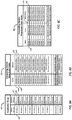
FIGS. 3A and4B-4C ,FIG. 3A shows anexample multi-array 40 including adata matrix 42. Thedata matrix 42 includes at least onemember 44 and a plurality ofdata elements member 44. As shown in the example ofFIG. 3A , thedata elements controller 20 in a value-timestamp format or as a value-timestamp pair, although this designation and/or terminology is not intended to be limiting. As shown in the example herein, each value of therespective data elements second data elements data element pair member 44 defining thedata element pair member 44 is defined by the automatedsystem 10 and corresponds to at least onesensor 14 included in theautomated system 10 and in communication with thecontroller 20. For example, themember 44 may correspond to one ormore sensors 14, or to one ormore sensors 14 in communication with and/or configured to sense and/or monitor at least one of adevice 12, an operation performed by the automatedsystem 10, or a sub-system of the automatedsystem 10, such as an assembly or manufacturing line, a machine including at least onedevice 12, a group ofdevices 12, etc. -
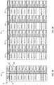
FIGS. 4B-4C show a multi-array 40 configured for use in capturing automation data from the automatedsystem 10 performing the sequence ofoperations 16 shown inFIG. 2 . As shown inFIGS. 4B-4C , the multi-array 40 consists of asingle data matrix 42, where eachmember 44 of the multi-array 40 is associated with a respective operation of the sequence ofoperations 16 and eachmember 44 defines afirst element 46 corresponding to the start time of the respective operation and defines asecond element 48 corresponding to the end time of the respective operation. As such, eachmember 44 of the multi-array 40 is associated with at least onesensor 14 of the automatedsystem 10, where the associatedsensor 14 provides input data to thecontroller 20 to determine the respective start and end times defining first andsecond elements first member 44 of the multi-array 40 shown inFIG. 4C is associated withOperation 1 of the sequence ofoperations 16, is labeled "Device 1 Work Position" in the multi-array, and is defined by a start time T0 (first element 46) and an end time T1 (second element 48). Thesecond member 44 of the multi-array 40 is associated withOperation 2 of the sequence ofoperations 16, is labeled "Device 2 Work Position" in the multi-array, and is defined by a start time T1' (first element 46) and an end time T2 (second element 48). The multi-array 40 is configured to include amember 44 corresponding to each of the tenoperations Operation 1 throughOperation 10, and a first andsecond element - Referring again to
FIG. 2 , upon detecting the end ofOperation 1 at end time T1, thecontroller 20, following the sequence ofoperations 16, triggersOperations FIG. 4C ), such thatOperations Devices controller clock 24 and recorded by thecontroller 20 inmulti-array 40 in the respective start location time as the element value of the respectivefirst data elements 46 defined by the respective members "Device 2 Work Position" associated withOperation 2 and "Device 3 Work Position" associated withOperation 3. WhenOperation 2 ends, e.g., whenDevice 2 is advanced to and reaches the Work Position, sensor S4 is triggered and generates an output which is detected as input data by thecontroller 20 during a scan cycle at an end time T2 determined by thecontroller clock 24. The end time T2 is measured by thecontroller clock 24 and recorded by thecontroller 20 inmulti-array 40 in the end time location as the element value of thesecond data element 48 defined by thesecond member 44 labeled "Device 2 Work Position." Similarly, whenOperation 3 ends, e.g., whenDevice 3 is advanced to and reaches the Work Position, sensor S6 is triggered and generates an output which is detected at time T2' as input data by thecontroller 20. The end time T2' is measured by thecontroller clock 24 and recorded by thecontroller 20 inmulti-array 40 in the end time location as the element value of thesecond data element 48 of thethird member 44 labeled "Device 3 Work Position." - Upon detecting the completion of the group of
concurrent Operations controller 20, following the sequence ofoperations 16, triggersOperation 4 at a time T2" (seeFIG. 4C ). The time T2" is measured by thecontroller clock 24 and recorded in the multi-array 40 in the start time location as the element value of thefirst data element 46 of the fourth member "Device 4 Work Position" associated withOperation 4. WhenOperation 4 ends, e.g., whenDevice 4 is advanced to and reaches the Work Position, sensor S8 is triggered and generates an output which is detected as input data by thecontroller 20 during a scan cycle at an end time T3 determined by thecontroller clock 24. The end time T3 is measured by thecontroller clock 24 and recorded by thecontroller 20 inmulti-array 40 in the end time location as the element value of thesecond data element 48 defined by thefourth member 44 labeled "Device 4 Work Position." - Upon detecting the completion of
Operation 4 at time T3, thecontroller 20, following the sequence ofoperations 16, triggersOperation 5 at a time T3' (seeFIG. 4C ). The time T3' is measured by thecontroller clock 24 and recorded in the multi-array 40 in the start time location as the element value of thefirst data element 46 of the fifth member "Device 5 Work Position" associated withOperation 5. WhenOperation 5 ends, e.g., whenDevice 5 is advanced to and reaches the Work Position, sensor S10 is triggered and generates an output which is detected as input data by thecontroller 20 during a scan cycle at an end time T4 determined by thecontroller clock 24. The end time T4 is measured by thecontroller clock 24 and recorded by thecontroller 20 inmulti-array 40 in the end time location as the element value of thesecond data element 46 defined by thefifth member 44 labeled "Device 5 Work Position." - As shown by
FIGS. 1 and4A-4C , thecontroller 20, upon detecting the completion ofOperation 5 at end time T4, triggers the start ofOperation 6 "Return Device 1 to Home Position" at start time T4'. The start time T4' is measured by thecontroller clock 24 and recorded as the element value of thefirst element 46 defined by thesixth member 44 labeled "Return Device 1 to Home Position." WhenOperation 6 ends, e.g., whenDevice 1 is returned to and reaches the Home Position, sensor S1 is triggered and generates an output which is detected as input data by thecontroller 20 during a scan cycle at an end time T5 determined by thecontroller clock 24, which is recorded in the multi-array 40 as the element value of thesecond element 48 of thesixth member 44 labeled "Return Device 1 to Home Position." - The process repeats in the same manner for the remaining
operations Operation 7 throughOperation 10 respectively associated with the seventh through tenth members of the multi-array 40, with thecontroller 20 continuing to execute the scan cycle at the scan frequency defined by the controller, wherein executing the scan cycle includes triggering each subsequent operation of the sequence ofoperations 16 using thelogic 28 provided to thecontroller 20 upon detection of completion of the prior operation by thecontroller 20, recording a respective start time (T5', T5', T6", T7' as shown inFIG. 4C ) measured by thecontroller clock 24, storing each of the respective start times in the multi-array 40 as a respective element value of a respectivefirst element 46 of arespective member 44 associated with arespective Operation 7 through 10, detecting sensor input data provided by a respective sensor S3, S5, S7, S9 during the scan cycle indicating the respective Device D7 through D10 has returned to its Home Position, recording a respective end time (T6, T6', T7, T8 as shown inFIG. 4C ) corresponding to respective sensor input data received by thecontroller 20 during a scan cycle, where each of the respective end times is measured by thecontroller clock 24, and storing each of the respective end times in the multi-array 40 as a respective element value of a respectivesecond element 48 of arespective member 44 associated with arespective Operation 7 through 10. As shown inFIGS. 4A-4C ,Operations - The
controller 20 may continue to execute thecontroller logic 28 and scan cycle such that theautomated system 10 continues to repeat the sequence ofoperations 16, wherein each performance of the sequence ofoperations 16 by the automatedsystem 10 may be referred to as an operational cycle of the automatedsystem 10. Thecontroller 20 updates the values of each of theelements controller 20 from the at least onesensor 14 associated with therespective element element element controller 20 monitors and/or updates each of the element values of the first andsecond elements controller 20 may be configured to compare the element value stored in a controller memory location corresponding to thedata element respective data element respective data element respective element respective element - As will be discussed in additional detail herein, the
computing device 30 may be configured to execute a data capture cycle which includes reading and collecting data stored in the multi-array 40 and storing the collected data to a first data table configured in thememory 36 of thecomputing device 30 to correspond to the multi-array 40, where the first data table may be configured, for example, as a raw data table 50 shown inFIG. 5B and corresponding to the multi-array 40 shown inFIG. 5A . The data capture rate of thecomputing device 30 may be of longer duration than the scan rate of thecontroller 20, and/or the data capture frequency defined by thecomputing device 30 may be less than the scan frequency of thecontroller 20 such that the element value of the eachelement FIGS. 5A and 5B and assuming for example that the scan rate is 10 ms and equal to the scan frequency, and the data capture rate is 50 ms and equal to the data capture frequency, it would be understood that five scan cycles would be completed in the elapsed time between data capture cycles, such that the element values may change up to 5 times between subsequent data capture cycles. - To prevent loss of the automation data including timing data represented by the element values stored to the multi-array 40 between data capture cycles, e.g., to allow collection of automation data including timing data from most or all of the operational cycles performed by the
automated equipment 10, other configurations of the multi-array 40 may be used to capture automation data including timing data from thesensors 14 at different frequencies and time intervals. For example, the multi-array 40 may be configured such that eachsensor 14 or each operation of the sequence ofoperations 16 may be associated with a set ofmembers 44 in the multi-array 40, to allow flexibility in the data capture method and to increase the number of operational cycles of the automatedsystem 10 from which automation data including timing data may be collected. In one example, a set ofmembers 44 may be associated with a set or pattern of scan cycles from which element values are recorded into the multi-array 40. By way of illustrative example, a set of scan cycles may include five sequential scan cycles executed by thecontroller 20, where each scan cycle has a scan rate of 10 ms and the scan cycles are executed at a scan frequency equal to the scan rate, such that the set of five scan cycles is repeatedly executed by thecontroller 20 every 50 ms. The set ofmembers 44 may include fivemembers 44, where each of the fivemembers 44 is each associated with thesame sensor 14 or operation and with a different scan cycle of the set of scan cycles. - For example, the set of
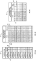
members 44 may be associated with an operation such asOperation 4 "Advance Device 4 to Work Position" and sensor S8 configured to sense whenDevice 4 is advanced to the work position. Now referring to the multi-array 40 shown inFIGS. 3A and6A , each ofMembers 4 through 8 may be associated withOperation 4 and a different scan cycle of the set of scan cycles such thatMember 4 may include first andsecond elements Member 5 may include first andsecond elements Member 6 may include first andsecond elements Member 7 may include first andsecond elements Member 8 may include first andsecond elements - Using the example of a data capture cycle executed by the computing device every 50 ms, a raw data table 50 may be configured to correspond with the multi-array 40 described in the present example, such that the raw data table 50, which may also be referred to herein as a first data table, would include locations corresponding to each of the
data elements 46. 48 in the multi-array 40, e.g., would include locations to receive the element values of each of thedata elements member 44, e.g., defined by each ofMembers 1 through Members N shown inFIGS. 3A and6A , including each ofMembers 4 through 8 each associated with a different scan cycle of the set of five scan cycles ofOperation 4 executed by thecontroller 20 between subsequent data capture cycles executed by thecomputing device 30. - Other configurations of the multi-array 40 may be used to collect automation data, including timing data, from scan cycles executed by the
controller 20 between subsequent data capture cycles executed by thecomputing device 30. For example, and referring to 3B, the multi-array 40 may be configured to include a plurality ofdata matrices 42, identified asMatrix 1 throughMatrix 4, wherein each of thedata matrices 42 is configured to collect automation data from the scan cycle executed by thecontroller 20 at a collection frequency defined by one or more predetermined time intervals or by a predetermined set or pattern of scan cycles executed by thecontroller 20. In one example, each of thedata matrices 42 of the multi-array 40 shown inFIG. 3B may be configured as shown for thedata matrix 42 ofFIG. 4C corresponding to theautomated system 10 and sequence ofoperations 16 ofFIGS. 1 and 2 . Thecontroller 12 may be configured to define a collection frequency for the multi-array 40 such that automation data collected during a first scan cycle of a set of four scan cycles is stored inMatrix 1 of the multi-array 40 (seeFIG. 3B ), automation data collected during a second scan cycle of the set of scan cycles is stored inMatrix 2, automation data collected during a third scan cycle of the set of scan cycles is stored inMatrix 3, and automation data collected by thecontroller 20 during a fourth scan cycle of the set of scan cycles is stored inMatrix 4. A first data table 50 configured by thecomputing device 30 to correspond to the multi-array 40 shown inFIG. 3B would be used to receive the automation data read by thecomputing device 30 from the fourdata matrices 42 during each data capture cycle executed by thecomputing device 30. Therefore, automation data from four scan cycles corresponding to four operational cycles of the sequence ofoperations 16 would be collected during each data capture cycle, thereby increasing data collection efficiency and the number of operational cycles of automation data collected as a proportion of the number of total operational cycles performed by the automatedsystem 10. In another example, each of thedata matrices 42 of the multi-array 40 may be configured to collect data from scan cycles executed at defined intervals. For example,Matrices Matrix 4 may be configured to collect automation data from all scan cycles such that the automation data may be constantly updated inMatrix 4. - The example shown in
FIG. 3B is non-limiting, and it is understood that the plurality ofdata matrices 42 included in the multi-array 40 may number more or less than the fourdata matrices 42 shown in the example provided herein to provide flexibility in data collection relative to scan rates, data capture rates, data storage configuration, communication network configuration, etc. Each of thematrices 42 of the multi-array 40 may be configured to includemultiple members 44 corresponding to asensor 14, as previously discussed. Eachmatrix 42 of the multi-array 40 may include a different set ofmembers 44 and data elements defined thereby. For example, and referring again to the multi-array shown inFIG. 3B ,Matrix 1 may include a first set ofN1 members 44 which may differ from the second, third and fourth sets of N2, N3,N4 members 44 respectively included inMatrices Matrix 1 may correspond to the plurality of devices D1-D5 and sensors S1-S10 and sequence ofoperations 16 shown inFIGS. 1-2 , the second set of N2 members included inMatrix 2 may correspond to one or more sensors associated with a machine (not shown) included in theautomated system 10, the third set of N3 members included inMatrix 3 may correspond to one or more sensors associated with an assembly or manufacturing line (not shown) included in theautomated system 10, wherein the data elements defined by each of the members of the three sets of members N1, N2, N3 define automation data associated with the respective automated operations performed by the automatedsystem 10. The fourth set of N4 members included inMatrix 4 may correspond with a plurality ofsensors 14 configured to sense the operating environment of the automatedsystem 10, such that the data elements defined by each of the members of member set N4 may represent values other than timing data. Non-limiting examples of members and data elements defining values other than timing data may include sensors configured to monitor or sense environmental factors such as ambient temperature, air pressure or humidity, light intensity, machine temperatures, fluid temperature, pressure or flow, etc. - Referring now to
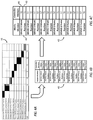
FIGS. 5A-5C and6A-6C , shown is a multi-array 40 configured by thecontroller 20, a first or raw data table 50 configured by thecomputing device 30 to correspond to the multi-array 40, and a second or processed data table 52 configured by the computing device to receive data processed from the first data table 50 and associated with an operation or member of the automatedsystem 10 such that the processed data may be saved to adatabase 38 and/or further analyzed by thecomputing device 30, for example, to determine a cycle time corresponding to an operation,device 12, ormember 44 of the automatedsystem 10.FIGS. 5B-5C illustrate configurations of first and second data tables 50, 52 corresponding to the multi-array 40 shown inFIGS. 5A and4C defined by the example sequence ofoperations 16 shown inFIG. 2 .FIGS. 6B-6C illustrate configurations of the first and second data tables 50, 52 corresponding to the multi-array 40 including asingle data matrix 42 shown inFIGS. 6A and3A . - The examples shown in
FIGS. 5A-6C are non-limiting, and other configurations of the first and second data tables 50, 52 may be provided by thecomputing device 30 to correspond to a multi-array 40 configured by thecontroller 20. For example, a first and second data table 50, 52 may be configured by thecomputing device 30 to correspond with the multi-array 40 shown inFIG. 3B , such that data element values defined by eachrespective data element respective member 44 of eachrespective data matrix 42 of the multi-array 40 collected by thecontroller 20 has a corresponding location in the first data table 50 configured by thecomputing device 30, and such that thecomputing device 30 may configure a second data table 52 to receive data processed from the first data table 50 for association with itsrespective member 44 and storage in thedatabase 38. - As described previously, the
computing device 30 may be configured to execute a data capture cycle to collect element values from the multi-array 40 stored in thecontroller memory 26, and to write the captured data into a first data table 50 configured by thecomputing device 30 to correspond to the multi-array 40. Thecomputing device 30 may include adata collector 34 configured to execute the data capture cycle at a data capture frequency, which may, but is not required to be, equivalent to a data capture rate defined by the data capture cycle. The data capture rate may be further defined and/or affected by the configuration of thecomputing device 30, the configuration of the communications network or method of communication through which thecomputing device 30 and thecontroller 20 are in communication with each other, etc. - The multi-array 40 is configured by the
controller 20 to include at least onemember 44 and a plurality ofelements member 44. The multi-array 40 is configured such that a memory location is allocated in thecontroller memory 26 to store the multi-array 40, where the memory location storing the multi-array 40 may be referred to herein as the multi-array memory location. Within the multi-array memory location, a respective controller memory location is defined for each of therespective elements respective member 44 of the multi-array 40. The size of the memory for eachelement - The first data table 50 is configured by the
computing device 30 to correspond with the configuration of the multi-array 40 from which thecomputing device 30 will collect data using the data capture cycle. The first data table 50, also referred to as the raw data table, is configured to receive an element value for eachrespective element computing device 30 from the multi-array 40 during a data capture cycle, such that the element value may be written by thecomputing device 30 into the raw data table 50 in a table location defined by the raw data table 50 and corresponding to the controller memory location for thatrespective element respective element computing device 30, such that each of the controller memory locations for eachrespective element computing device memory 36. As shown inFIGS. 5A-5B andFIGS. 6A-6B , the first data table 50 may be configured differently from the multi-array 40, which may include, as shown in the referenced figures, providing more than onelocation member 44 associated with each of the table locations allocated in the data table 50 as corresponding to theelements - By configuring the data capture cycle such that the
computing device 30 reads the multi-array 40, e.g., reads the multi-array memory location allocated for the multi-array 40 in thecontroller memory 26, and writes the element values read from the controller memory locations of the multi-array memory location into the corresponding table locations of the raw data table 50, data capture efficiencies can be realized using the multi-array 40 and table data structures described herein, as compared to reading and storing individual data points using a point to point data collection method. To provide efficiency of data storage, use of memory and data capture rates, thecomputing device 30 may be configured to compare, during a current data capture cycle, the prior element value stored in a table location of the first data table 50 during a prior data capture cycle with the current element value stored in the corresponding controller memory location of eachrespective data element computing device memory 36 for therespective element computing device memory 36 is updated by storing the current element value in the first table location in thecomputing device memory 36 corresponding to the controller memory location for the changedrespective element - Referring again to
FIGS. 5A-5C and6A-6C , thecomputing device 30 may configure a second data table 52, which may be referred to herein as a processed data table 52, to convert the respective element value from the first data table 50 to the second data table 52 such that each of the respective element values read into the first data table 50 during the data capture cycle is associated in the second data table 52 with themember 44 defining theelement FIGS. 5A-5C , in response to input data received by thecontroller 20 during a scan cycle, thecontroller 20 may determine element values respectively corresponding to the start time and end time T0, T1 for the operational cycle ofOperation 1 scanned during the scan cycle, and store these element values to their respective controller memory locations allocated in thecontroller memory 26 for the first andsecond elements computing device 30 reads the multi-array 40 and collects the element values of the start time and end time T0, T1 determined for the operational cycle ofOperation 1 scanned by thecontroller 20 and stored in the multi-array memory location, and writes these element values to the raw data table 50. The raw data table 50 has been configured, for example, to provide a first table location associated with aname 44A shown as "Device 1.WorkPosition.0", where the first table location corresponds to thefirst element 46 defined by themember 44 "Device 1 Work Position." The element value of the start time T0 read from the multi-array 40 is written to the first table location corresponding to thefirst element 46. Similarly, a second table location is associated with aname 44B shown as "Device1.WorkPosition.1", where the second table location corresponds to thesecond element 48 defined by themember 44 "Device 1 Work Position." The element value of the end time T1 read from the multi-array 40 is written to the table location shown inFIG. 5B corresponding to thesecond element 48 defined by themember 44 "Device 1 Work Position." - The
computing device 30 may process the first data table 50 to convert the element values for the start and end times T0, T1 stored in the first data table 50 to the second data table 52. As shown inFIG. 5C , the second data table includes thefirst member 44 named "Device1.WorkPosition" associated with the first andsecond elements member 44 respectively as the start time and end time T0, T1 ofOperation 1 described as "Advance Device 1 to Work Position" inFIG. 2 , where thefirst member 44 corresponds toOperation 1. The element values, e.g., the timing data or timestamps, written into the first data table 50 for the start and end times T0, T1 of the operational cycle scanned to determine the start and end times T0, T1 for that operational cycle are converted by thecomputing device 30 and associated with the member "Device1.WorkPosition." The second data table 52 including the element values of the start and end times T0, T1 for the scanned operational cycle may be stored in adatabase 38 using thecomputing device 30, and/or the element values of the start and end times T0, T1 determined for the scanned operational cycle may be associated, for example, with metadata identifying the associatedmember 44 and operational cycle from which the start and end times T0, T1 were determined. To complete the data capture cycle, thecomputing device 30 may read the remaining element values of the remaining data elements T1' through T8 shown in the multi-array 40 ofFIG. 5A from the multi-array 40, write these remaining element values into the first data table 50 shown inFIG. 5B , convert the remaining element values into the second data table 52 for association with therespective member 44 corresponding to each remaining element value, and store the converted element values such that they are associated with therespective member 44 corresponding to each element value and the operational cycle and/or scan cycle from which the stored element value was determined. The data capture cycle may be repeated such that element values associated with subsequent operational cycles of the sequence ofoperations 16 performed by the automatedsystem 10 and/or determined by subsequent scan cycles executed by thecontroller 10 may be converted for association with the respective member defining theelement element - The
computing device 30 may be configured to analyze the element values, which may include analyzing the start time and end time values of amember 44 for an operational cycle or scan cycle to determine a cycle time for themember 44. For example, a cycle time ofOperation 1 may be calculated by determining the difference between the element value (timing data or time stamp) of the start time T0 and the element value (timing data or time stamp) of the end time T1, wherein each of these values is determined using thecontroller clock 24 and input data received by thecontroller 20 during execution of a scan cycle and/or performance of an operational cycle of the sequence ofoperations 16. The cycle time and/or related timing data for that operational/scan cycle may be stored in thedatabase 38, as described previously, as a prior operational/scan cycle. The data capture cycle may be repeated according to the data capture frequency to convert and store timing data from a plurality of prior operational cycles to provide historical cycle time and timing data stored to thedatabase 38. Cycle time and/or related timing data for a current operational cycle may be determined for analysis and/or comparison with the historical data by thecomputing device 30. - The illustrative examples described herein are intended to be non-limiting. For example, at least one of the
devices 12 may be dissimilar from theother devices 12, and at least one of thesensors 14 may be dissimilar from theother sensors 14. Theautomated system 10 may be arranged such that asingle sensor 14 may be configured and used to sense the first state and the second state of an associateddevice 12 and to output a signal corresponding to the sensed one of the first and second state. Asingle sensor 14 may be configured to sense a designated state of a group ofdevices 12, and to output a signal corresponding a sensed state of the group ofdevices 12. In one example, the sensed state of the group ofdevices 12 triggering an output from thesensor 14 may correspond to thesensor 14 sensing afirst device 12 of the group ofdevices 12 reaching the designated state. In another example, the sensed state of the group ofdevices 12 triggering an output from thesensor 14 may correspond to thesensor 14 sensing thelast device 12 of the group ofdevices 12 reaching the designated state, e.g., sensing that all devices of the group ofdevices 12 have reached the designated state. - The detailed description and the drawings or figures are supportive and descriptive of the invention, but the scope of the invention is defined solely by the claims. While some of the best modes and other embodiments for carrying out the claimed invention have been described in detail, various alternative designs and embodiments exist for practicing the invention defined in the appended claims.
Claims (23)
- A method for capturing automation data comprising:executing a scan cycle using a controller (20) configured as an automation controller;collecting input data during the scan cycle from at least one sensor (14) in communication with the controller (20);wherein:the at least one sensor (14) corresponds to at least one member;the at least one member is defined by a plurality of elements;each respective element of the plurality of elements has a respective element value determined by the input data;determining each respective element value for the scan cycle using the input data collected during the scan cycle;configuring a multi-array (40) using the controller (20), wherein:the multi-array (40) includes the at least one member and the plurality of elements defined by the at least one member;configuring the multi-array (40) includes:allocating a multi-array memory location to store the multi-array (40) in the controller (20);the multi-array memory location including a respective controller memory location for each respective element of the plurality of elements defined by the at least one member;storing the element value of each respective element for the scan cycle in the respective controller memory location in the multi-array (40);the controller (20) includes a controller clock (24);the scan cycle is defined by a sequence of operations (16); characterised in that:the at least one member corresponds to an operation of the sequence of operations (16);the plurality of elements defined by the at least one member includes a first element and a second element;the first element is defined by the start of the operation;the second element is defined by the end of the operation;the element value of the first element is defined by the start time of operation determined by the controller clock (24); andthe element value of the second element is defined by the end time of the operation determined by the controller clock (24).
- The method of claim 1, further comprising:executing the scan cycle a plurality of times using the controller (20), to provide a plurality of scan cycles including a current scan cycle and a prior scan cycle;wherein the prior scan cycle precedes the current scan cycle;determining the respective element value for each respective scan cycle of the plurality of scan cycles using the input data collected during the respective scan cycle;for each respective element of the plurality of elements, comparing a current element value of the respective element determined from the current scan cycle to a prior element value of the respective element determined from the prior scan cycle to determine whether the current element value is changed from the prior element value; andstoring the current element value of each respective element for the scan cycle in the respective controller memory location for the respective element when the current element value is changed from the prior element value.
- The method of claim 1, wherein:the at least one sensor (14) includes a plurality of sensors (14);collecting input data during the scan cycle includes collecting input data from the plurality of sensors (14);wherein the at least one member corresponds to the plurality of sensors (14); anddetermining each respective element value for the at least one value for the scan cycle including using input data collected from the plurality of sensors (14) during the respective scan cycle.
- The method of claim 1, wherein:the at least one sensor (14) is a sensor (14) configured to provide input data including a first input and an at least second input different from the first input;the at least one member includes:a first member corresponding to the sensor (14) and defined by a first plurality of elements each having a respective element value determined by the first input; andan at least second member corresponding to the sensor (14) and defined by an at least second plurality of elements each having a respective element value determined by the at least second input;the multi-array (40) includes the first member, the at least second member, the first plurality of elements, and at least second plurality of elements;the multi-array memory location includes a respective controller memory location for each respective element of the first and at least second plurality of elements; andthe method further comprising:storing the respective element value of each respective element of the first and at least second plurality of elements for the scan cycle in the respective controller memory location of each respective element of the first and at least second plurality of elements in the multi-array (40).
- The method of claim 1, wherein:the at least one member is defined by the at least one sensor (14) in communication with a device (12); andeach of the plurality of elements is determined by a state of the device (12).
- The method of claim 1, wherein:the at least one member is defined by a group of devices (12);the at least one sensor (14) is in communication with the group of devices (12); andthe first element is determined by a first state of the group of devices (12) and the second element is determined by a second state of the group of devices (12).
- The method of claim 1, further comprising:executing a plurality of scan cycles using the controller (20);wherein executing the plurality of scan cycles includes executing a repeating set of scan cycles;wherein:the at least one member includes a set of members;the multi-array (40) includes the set of members;each respective member of the set of members is associated with a respective scan cycle of the repeating set of scan cycles; anddetermining each respective element value for the each respective member of the set of members includes using input data collected during the respective scan cycle of the repeating set of scan cycles.
- The method of claim 1, the method further comprising:executing a plurality of scan cycles using the controller (20);wherein:the multi-array (40) includes a first data matrix and at least a second data matrix;the at least one member includes an at least one first matrix member and an at least one second matrix member;the first data matrix includes the at least one first matrix member and the plurality of elements defined by the at least one first matrix member;the second data matrix includes the at least one second matrix member and the plurality of elements defined by the at least one second matrix member;the multi-array memory location is configured to include a respective controller memory location for each respective element of the plurality of elements defined by the at least one first matrix member and the at least one second matrix member;defining a collection frequency for the first data matrix and the at least second data matrix;storing the element value of each respective element for the plurality of scan cycles in the respective controller memory location in the first data matrix and the at least second data matrix according to the collection frequency.
- The method of claim 8, wherein the at least one first matrix member and the at least one second matrix member are configured as the same member.
- The method of claim 8, wherein:the scan cycle is characterized by a scan rate; andthe collection frequency is defined relative to the scan rate.
- The method of claim 1, further comprising:providing a computing device (30) in communication with the controller (20);configuring a first data table (50) using the computing device (30);wherein configuring the first data table (50) includes storing the respective controller memory location for each of a respective element in the computing device (30) such that each of the controller memory locations for each respective element is associated with a corresponding location in the first data table (50) to provide a plurality of corresponding locations;executing a data capture cycle using the computing device (30);reading the multi-array memory location of the controller (20) during the data capture cycle using the computing device (30);writing each respective element value read from the multi-array memory location of the controller (20) into the corresponding location of the first data table (50).
- The method of claim 11, wherein:the scan cycle is characterized by a scan rate;the capture cycle is characterized by a capture rate of longer duration than the scan rate.
- The method of claim 11, wherein reading the multi-array memory location of the controller (20) includes reading each respective controller memory location of the multi-array memory location.
- The method of claim 13, further comprising:executing the data capture cycle a plurality of times using the computing device (30) to provide a plurality of data capture cycles including a current data capture cycle and a prior data capture cycle;wherein the prior data capture cycle precedes the current data capture cycle;for each respective controller memory location in the multi-array (40), comparing a current element value read from each respective controller memory location during the current data capture cycle to a prior element value stored in a respective corresponding location in the first data table (50) to determine whether the current element value is changed from the prior element value; andstoring the current element value of each respective element read from the respective controller memory location in the respective corresponding location of the first data table (50) when the current element value is changed from the prior element value.
- The method of claim 11, further comprising:configuring a second data table (50) using the computing device (30);wherein the second data table (50) is configured to convert the respective element values of the plurality of elements written into the plurality of corresponding locations of the first data table (50) into the second table such that the at least one member is associated with the respective element values of the plurality of elements defined by the at least one member;wherein executing the data capture cycle using the computing device (30) further includes converting the element values written into the first data table (50) into the second data table (50);storing the second data table (50) in a database (38) using the computing device (30);wherein the respective element values of the plurality of elements defined by the at least one member are associated with the at least one member in the database (38).
- The method of claim 15, further comprising:executing the data capture cycle a plurality of times using the computing device (30), to provide a plurality of data capture cycles; andwherein storing the second data table (50) in a database (38) using the computing device (30) includes storing the respective element values of the plurality of elements from the plurality of data capture cycles such that the respective element values associated with the at least one member from one of the plurality of data capture cycles can be compared with the respective element values associated with the at least one member from another of the plurality of data capture cycles.
- The method of claim 16, wherein:the controller (20) includes a controller clock (24);the plurality of elements defined by the at least one member includes a first element and a second element;the first element is defined by a start state of the member;the second element is defined by an end state of the member;the element value of the first element is a start time defined by the time of start condition determined by the input data and measured by the controller clock (24);the element value of the second element is an end time defined by the time of the end condition determined by the input data and measured by the controller clock (24); anda cycle time for the member is defined by the start time and the end time;the method further comprising:determining a first cycle time for the at least one member using the computing device (30);wherein the first cycle time is defined by the respective first and second element values associated with the at least one member from one of the plurality of data capture cycles.
- The method of claim 17, the method further comprising:determining a second cycle time for the at least one member using the computing device (30);wherein the second cycle time is defined by the respective first and second element values associated with the at least one member from another of the plurality of data capture cycles; andcomparing the first cycle time and the second cycle time using the computing device (30).
- A system comprising:a controller (20) including a controller clock (24);wherein the controller (20) is configured as an automation controller;a plurality of sensors (14) in communication with the controller (20);a computing device (30) in communication with the controller (20);wherein the controller (20) is programmed to:execute a scan cycle at a scan frequency;wherein the scan cycle is defined by a sequence of operations (16) including at least one operation;collect input data during the scan cycle from the plurality of sensors (14);wherein the at least one operation corresponds to at least one sensor (14) of the plurality of sensors (14);configure a multi-array (40) including at least one member and a first element and a second element defined by the at least one member;wherein:the at least one member corresponds to the at least one operation;the first element has a first element value corresponding to a start time of the at least one operation and defined by the input data;the second element has a second element value corresponding to an end time of the at least one operation and defined by the input data;the first and second element values are determined during the scan cycle by the input data and the controller clock (24);wherein configuring the multi-array (40) includes:allocating a multi-array memory location in the controller (20);the multi-array memory location including a respective controller memory location for each of the first element and the second element defined by the at least one member;determine the first and second element values during the scan cycle using the controller (20);store the element value of each respective element defined by the at least one member for the scan cycle in the respective controller memory location in the multi-array (40);wherein the computing device (30) is programmed to:configure a first data table (50) using the computing device (30);wherein configuring the first data table (50) includes storing the respective controller memory location for each respective element in the computing device (30) such that each of the controller memory locations for each respective element is associated with a corresponding location in the first data table (50) to provide a plurality of corresponding locations;execute a data capture cycle at a data capture frequency;read the multi-array memory location of the controller (20) during the data capture cycle; andwrite each respective element value read from the multi-array memory location of the controller (20) into the corresponding location of the first data table (50).
- The system of claim 19, wherein:the first element is a value;the second element is a time stamp associated with the value; andthe first and second element is stored in the multi-array (40) as a value-time stamp pair.
- The system of claim 19, further comprising:the at least one sensor (14) in communication with at least two devices (12);the sequence of operations (16) including at least two concurrent operations;wherein:a respective device (12) of the at least two devices (12) performs each respective operation of the at least two concurrent operations;the at least one member includes at least two members corresponding to the at least two devices (12);each respective member of the at least two members defines a first element and a second element;the first element of the at least two members has a first element value corresponding to a start time of the at least two concurrent operations which is defined by the input data and is the same start time for each of the at least two members;the second element of each respective member of the at least two members has a second element value which is defined by the input data and corresponds to a respective end time of the respective one of the at least two concurrent operations performed by the respective member.
- The system of claim 19, further comprising:the computing device (30) including a database (38), the computing device (30) further programmed to:configure a second data table (50);wherein the second data table (50) is configured to convert the plurality of corresponding locations of the first data table (50) into the second table such that the at least one member is associated with the first and second elements defined by the at least one member;execute the data capture cycle including converting the element values written into the first data table (50) into the second data table (50); andstore the second data table (50) in the database (38);wherein the respective element values of the plurality of elements defined by the at least one member are associated with the at least one member in the database (38).
- The system of claim 19, further comprising:the computing device (30) programmed to determine a cycle time for the operation corresponding to the at least one member;wherein the cycle time is defined by the first and second element values associated with the at least one member in the database (38).
Priority Applications (1)
| Application Number | Priority Date | Filing Date | Title |
|---|---|---|---|
| EP17170782.1A EP3223096B1 (en) | 2011-12-06 | 2012-12-05 | Method and system for capturing automation data |
Applications Claiming Priority (3)
| Application Number | Priority Date | Filing Date | Title |
|---|---|---|---|
| US201161567208P | 2011-12-06 | 2011-12-06 | |
| US13/693,758 US9778652B2 (en) | 2011-12-06 | 2012-12-04 | Method and system for capturing automation data |
| PCT/US2012/067883 WO2013085959A2 (en) | 2011-12-06 | 2012-12-05 | Method and system for capturing automation data |
Related Child Applications (1)
| Application Number | Title | Priority Date | Filing Date |
|---|---|---|---|
| EP17170782.1A Division EP3223096B1 (en) | 2011-12-06 | 2012-12-05 | Method and system for capturing automation data |
Publications (2)
| Publication Number | Publication Date |
|---|---|
| EP2788829A2 EP2788829A2 (en) | 2014-10-15 |
| EP2788829B1 true EP2788829B1 (en) | 2017-05-17 |
Family
ID=48524560
Family Applications (2)
| Application Number | Title | Priority Date | Filing Date |
|---|---|---|---|
| EP12806762.6A Active EP2788829B1 (en) | 2011-12-06 | 2012-12-05 | Method and system for capturing automation data |
| EP17170782.1A Active EP3223096B1 (en) | 2011-12-06 | 2012-12-05 | Method and system for capturing automation data |
Family Applications After (1)
| Application Number | Title | Priority Date | Filing Date |
|---|---|---|---|
| EP17170782.1A Active EP3223096B1 (en) | 2011-12-06 | 2012-12-05 | Method and system for capturing automation data |
Country Status (6)
| Country | Link |
|---|---|
| US (2) | US9778652B2 (en) |
| EP (2) | EP2788829B1 (en) |
| JP (1) | JP6204372B2 (en) |
| KR (2) | KR102027104B1 (en) |
| CN (2) | CN104040448B (en) |
| WO (1) | WO2013085959A2 (en) |
Families Citing this family (17)
| Publication number | Priority date | Publication date | Assignee | Title |
|---|---|---|---|---|
| US10048670B2 (en) * | 2014-05-08 | 2018-08-14 | Beet, Llc | Automation operating and management system |
| WO2016003501A1 (en) * | 2014-07-03 | 2016-01-07 | General Electric Company | Acquisition of high frequency data in transient detection |
| KR101593834B1 (en) * | 2014-10-30 | 2016-02-12 | 엘에스산전 주식회사 | PLC system |
| US10984338B2 (en) | 2015-05-28 | 2021-04-20 | Raytheon Technologies Corporation | Dynamically updated predictive modeling to predict operational outcomes of interest |
| JP6520545B2 (en) * | 2015-08-10 | 2019-05-29 | オムロン株式会社 | Support device and support program |
| JP6680866B2 (en) * | 2015-08-24 | 2020-04-15 | ビート インク | Method and system for generating mechanical beats |
| KR101758558B1 (en) * | 2016-03-29 | 2017-07-26 | 엘에스산전 주식회사 | Energy managemnet server and energy managemnet system having thereof |
| EP3557453B1 (en) * | 2017-08-29 | 2023-05-03 | Siemens Aktiengesellschaft | Method and device for determining data reading period |
| US10802457B2 (en) * | 2017-10-23 | 2020-10-13 | Schneider Electric USA, Inc. | Centralized motor thermal memory management |
| US11468216B2 (en) | 2018-08-28 | 2022-10-11 | Linecraft Ai Limited | Method for building a model of a physical system |
| CN109947868A (en) * | 2019-03-22 | 2019-06-28 | 晶晨半导体(上海)股份有限公司 | A kind of signal display method of storage system |
| CN110135678A (en) * | 2019-03-29 | 2019-08-16 | 广州明珞汽车装备有限公司 | A kind of process timing sequence analysis method, system and storage medium based on station |
| CN110245374B (en) * | 2019-04-26 | 2023-06-16 | 广州明珞汽车装备有限公司 | Process time sequence interval analysis method, system, device and storage medium |
| JP7359601B2 (en) * | 2019-09-03 | 2023-10-11 | 株式会社日立製作所 | Data extraction device, data extraction method, and data extraction program |
| CN111681261B (en) * | 2020-04-22 | 2022-12-13 | 广州明珞汽车装备有限公司 | Gantt chart processing method and system based on motion positioning and storage medium |
| US11435715B2 (en) * | 2020-05-14 | 2022-09-06 | Hitachi, Ltd. | System and method for detecting change over in manufacturing field |
| CN115495498B (en) * | 2022-09-23 | 2023-06-16 | 共青科技职业学院 | Data association method, system, electronic equipment and storage medium |
Family Cites Families (40)
| Publication number | Priority date | Publication date | Assignee | Title |
|---|---|---|---|---|
| US4553224A (en) | 1983-08-04 | 1985-11-12 | Allen-Bradley Company | Multiplexed data handler for programmable controller |
| JPH01236306A (en) | 1988-03-17 | 1989-09-21 | Nissan Motor Co Ltd | Sequence controller |
| US5097470A (en) * | 1990-02-13 | 1992-03-17 | Total Control Products, Inc. | Diagnostic system for programmable controller with serial data link |
| US5285376A (en) * | 1991-10-24 | 1994-02-08 | Allen-Bradley Company, Inc. | Fuzzy logic ladder diagram program for a machine or process controller |
| US5991371A (en) * | 1993-12-07 | 1999-11-23 | Brother Kogyo Kabushiki Kaisha | Communication apparatus |
| GB2292620B (en) * | 1994-08-16 | 1998-04-22 | Motorola Israel Ltd | Event driven programmer logic controller processor arrangement |
| JP3447432B2 (en) * | 1995-06-07 | 2003-09-16 | 三菱電機株式会社 | Network data server device and programmable logic controller system |
| US6327511B1 (en) * | 1998-12-30 | 2001-12-04 | Schneider Automation, Inc. | Input/output (I/O) scanner for a control system with peer determination |
| US6499114B1 (en) * | 1999-02-17 | 2002-12-24 | General Electric Company | Remote diagnostic system and method collecting sensor data according to two storage techniques |
| SG74705A1 (en) * | 1999-03-12 | 2001-06-19 | Sony Electronics Singapore Pte | A monitoring system for monitoring processing equipment |
| US6993456B2 (en) * | 1999-09-30 | 2006-01-31 | Rockwell Automation Technologies, Inc. | Mechanical-electrical template based method and apparatus |
| GB0004194D0 (en) * | 2000-02-22 | 2000-04-12 | Nat Power Plc | System and method for monitoring a control process in a process plant |
| US7603289B2 (en) | 2001-07-13 | 2009-10-13 | Siemens Aktiengesellschaft | System and method for electronic delivery of content for industrial automation systems |
| US7027954B2 (en) * | 2001-12-21 | 2006-04-11 | Honeywell International Inc. | Method and apparatus for retrieving activity data related to an activity |
| TWI243339B (en) * | 2002-03-19 | 2005-11-11 | Casio Computer Co Ltd | Image reading apparatus and drive control method |
| DE60309572T2 (en) | 2002-03-21 | 2007-07-05 | United Parcel Service Of America, Inc. | System for recording and storing vehicle sensor data |
| US7117043B1 (en) * | 2002-03-28 | 2006-10-03 | Integrator.Com | Method for programming a programmable logic controller |
| JP4161189B2 (en) | 2002-12-27 | 2008-10-08 | オムロン株式会社 | Information monitoring support device and information monitoring system |
| CA2420828C (en) * | 2003-03-04 | 2011-08-02 | Executive Manufacturing Technologies Inc. | System and method for processing data relating to conditions in a manufacturing process |
| US7775245B2 (en) * | 2005-04-08 | 2010-08-17 | Air Products And Chemicals, Inc. | Secure loop system and method for supply and delivery of product contained in a carrier |
| JP2007213451A (en) | 2006-02-10 | 2007-08-23 | Omron Corp | Collected data monitoring method and device |
| CN101467184B (en) * | 2006-04-13 | 2013-03-13 | Igt公司 | Method and apparatus for integrating remotely-hosted and locally rendered content on a gaming device |
| WO2007146587A2 (en) * | 2006-06-15 | 2007-12-21 | Koninklijke Philips Electronics, N.V. | Integrated multi-channel time-to-digital converter for time-of-flight pet |
| US7917240B2 (en) * | 2006-09-29 | 2011-03-29 | Fisher-Rosemount Systems, Inc. | Univariate method for monitoring and analysis of multivariate data |
| US7853568B2 (en) * | 2007-03-01 | 2010-12-14 | Air Liquide Large Industries U.S. Lp | High speed data historian |
| US7941229B2 (en) * | 2007-06-06 | 2011-05-10 | Rockwell Automation Technologies, Inc. | High-speed sequential sampling of I/O data for industrial control |
| US7930639B2 (en) * | 2007-09-26 | 2011-04-19 | Rockwell Automation Technologies, Inc. | Contextualization for historians in industrial systems |
| US7657333B2 (en) * | 2007-09-27 | 2010-02-02 | Rockwell Automation Technologies, Inc. | Adjustment of data collection rate based on anomaly detection |
| CN101251483B (en) * | 2008-01-11 | 2010-06-16 | 北京金菩嘉医疗科技有限公司 | Test analytical instrument using surface plasma resonance oscillation detection technique |
| US7809458B2 (en) * | 2008-03-31 | 2010-10-05 | Honda Motor Co., Ltd. | Process control system with ability to exchange data with production line machine controllers |
| JP4600522B2 (en) | 2008-06-03 | 2010-12-15 | ソニー株式会社 | Process control apparatus and process control method |
| WO2010047150A1 (en) | 2008-10-20 | 2010-04-29 | 株式会社日立製作所 | Work information processor, program, and work information processing method |
| JP2010120394A (en) | 2008-11-17 | 2010-06-03 | Mannoh Co Ltd | Shift position detection device |
| JP2010170536A (en) * | 2008-12-26 | 2010-08-05 | Omron Corp | Programmable controller |
| US20100211192A1 (en) * | 2009-02-17 | 2010-08-19 | Honeywell International Inc. | Apparatus and method for automated analysis of alarm data to support alarm rationalization |
| JP4845982B2 (en) * | 2009-03-05 | 2011-12-28 | 株式会社日立製作所 | Information processing apparatus and management method of configuration information acquired from storage system |
| US8843221B2 (en) * | 2009-12-09 | 2014-09-23 | Comau Spa | Automation management system and method |
| CN101963797A (en) * | 2010-04-16 | 2011-02-02 | 中国矿业大学 | Embedded system based intrinsic safety type coal mining machine state monitoring and analyzing device |
| US9098612B2 (en) * | 2010-12-30 | 2015-08-04 | Qwest Communications International Inc. | End-to-end application tracking framework |
| US8615683B2 (en) | 2011-06-24 | 2013-12-24 | Rockwell Automation Technologies, Inc. | Capturing data during operation of an industrial controller for the debugging of control programs |
-
2012
- 2012-12-04 US US13/693,758 patent/US9778652B2/en active Active
- 2012-12-05 EP EP12806762.6A patent/EP2788829B1/en active Active
- 2012-12-05 CN CN201280066225.6A patent/CN104040448B/en active Active
- 2012-12-05 WO PCT/US2012/067883 patent/WO2013085959A2/en active Application Filing
- 2012-12-05 EP EP17170782.1A patent/EP3223096B1/en active Active
- 2012-12-05 JP JP2014546012A patent/JP6204372B2/en active Active
- 2012-12-05 CN CN201710141343.3A patent/CN107015554B/en active Active
- 2012-12-05 KR KR1020147018640A patent/KR102027104B1/en active IP Right Grant
- 2012-12-05 KR KR1020197027825A patent/KR102133855B1/en active IP Right Grant
-
2017
- 2017-08-29 US US15/689,052 patent/US10481593B2/en active Active
Also Published As
| Publication number | Publication date |
|---|---|
| CN104040448A (en) | 2014-09-10 |
| US20130144407A1 (en) | 2013-06-06 |
| CN107015554B (en) | 2020-02-14 |
| EP3223096A1 (en) | 2017-09-27 |
| KR102027104B1 (en) | 2019-10-01 |
| WO2013085959A2 (en) | 2013-06-13 |
| CN104040448B (en) | 2017-04-05 |
| US9778652B2 (en) | 2017-10-03 |
| JP2015505086A (en) | 2015-02-16 |
| US20170357252A1 (en) | 2017-12-14 |
| EP3223096B1 (en) | 2020-07-29 |
| KR20140098849A (en) | 2014-08-08 |
| KR102133855B1 (en) | 2020-07-16 |
| US10481593B2 (en) | 2019-11-19 |
| JP6204372B2 (en) | 2017-09-27 |
| KR20190113991A (en) | 2019-10-08 |
| EP2788829A2 (en) | 2014-10-15 |
| CN107015554A (en) | 2017-08-04 |
| WO2013085959A3 (en) | 2013-08-15 |
Similar Documents
| Publication | Publication Date | Title |
|---|---|---|
| US10481593B2 (en) | Method and system for capturing automation data | |
| EP3382485B1 (en) | Controller, control program, control system, and control method | |
| CN105631577B (en) | Data transmission method, analysis and prediction report method and system for robot | |
| EP2618263A2 (en) | Cache device, communication apparatus, and computer program product | |
| US20220100186A1 (en) | Control system for machine with a plurality of components and methods of operation | |
| JP2015505086A5 (en) | ||
| EP3454144B1 (en) | Control device and control method | |
| JP2018133037A (en) | Control device | |
| CN112673326A (en) | Control device and control program | |
| US10890889B2 (en) | Method of monitoring and assessing the operation of an industrial installation driven by a programmable controller and equipment implementing said method | |
| JP3277247B2 (en) | Method for creating an abnormality diagnosis reference pattern in an automated equipment system and an automatic diagnosis apparatus using the reference pattern | |
| JPH03135604A (en) | Annunciator for state change of control signal and controller with the annunciator | |
| CN103365237A (en) | Method and device for monitoring and recording component and variable in PLC (Programmable Logic Controller) system | |
| JP7441006B2 (en) | Control devices, control programs, and control systems | |
| US20150066164A1 (en) | System and method for dynamically reporting manufacturing data in a spreadsheet format | |
| US20130151528A1 (en) | Logging device, logging system and control method for logging device | |
| US7272540B2 (en) | Method and device for multistage data processing, of a power generating station | |
| WO2020136839A1 (en) | Control system | |
| JP2021060683A (en) | Data utilization system | |
| Yan et al. | Structural damage diagnosis based on stochastic subspace identification, Kalman model, and principal component analysis. |
Legal Events
| Date | Code | Title | Description |
|---|---|---|---|
| PUAI | Public reference made under article 153(3) epc to a published international application that has entered the european phase |
Free format text: ORIGINAL CODE: 0009012 |
|
| 17P | Request for examination filed |
Effective date: 20140703 |
|
| AK | Designated contracting states |
Kind code of ref document: A2 Designated state(s): AL AT BE BG CH CY CZ DE DK EE ES FI FR GB GR HR HU IE IS IT LI LT LU LV MC MK MT NL NO PL PT RO RS SE SI SK SM TR |
|
| DAX | Request for extension of the european patent (deleted) | ||
| GRAP | Despatch of communication of intention to grant a patent |
Free format text: ORIGINAL CODE: EPIDOSNIGR1 |
|
| STAA | Information on the status of an ep patent application or granted ep patent |
Free format text: STATUS: GRANT OF PATENT IS INTENDED |
|
| INTG | Intention to grant announced |
Effective date: 20161128 |
|
| GRAS | Grant fee paid |
Free format text: ORIGINAL CODE: EPIDOSNIGR3 |
|
| GRAA | (expected) grant |
Free format text: ORIGINAL CODE: 0009210 |
|
| STAA | Information on the status of an ep patent application or granted ep patent |
Free format text: STATUS: THE PATENT HAS BEEN GRANTED |
|
| AK | Designated contracting states |
Kind code of ref document: B1 Designated state(s): AL AT BE BG CH CY CZ DE DK EE ES FI FR GB GR HR HU IE IS IT LI LT LU LV MC MK MT NL NO PL PT RO RS SE SI SK SM TR |
|
| REG | Reference to a national code |
Ref country code: GB Ref legal event code: FG4D |
|
| REG | Reference to a national code |
Ref country code: CH Ref legal event code: EP |
|
| REG | Reference to a national code |
Ref country code: IE Ref legal event code: FG4D |
|
| REG | Reference to a national code |
Ref country code: AT Ref legal event code: REF Ref document number: 895017 Country of ref document: AT Kind code of ref document: T Effective date: 20170615 |
|
| REG | Reference to a national code |
Ref country code: DE Ref legal event code: R096 Ref document number: 602012032625 Country of ref document: DE |
|
| REG | Reference to a national code |
Ref country code: NL Ref legal event code: MP Effective date: 20170517 |
|
| REG | Reference to a national code |
Ref country code: LT Ref legal event code: MG4D |
|
| REG | Reference to a national code |
Ref country code: AT Ref legal event code: MK05 Ref document number: 895017 Country of ref document: AT Kind code of ref document: T Effective date: 20170517 |
|
| PG25 | Lapsed in a contracting state [announced via postgrant information from national office to epo] |
Ref country code: NO Free format text: LAPSE BECAUSE OF FAILURE TO SUBMIT A TRANSLATION OF THE DESCRIPTION OR TO PAY THE FEE WITHIN THE PRESCRIBED TIME-LIMIT Effective date: 20170817 Ref country code: LT Free format text: LAPSE BECAUSE OF FAILURE TO SUBMIT A TRANSLATION OF THE DESCRIPTION OR TO PAY THE FEE WITHIN THE PRESCRIBED TIME-LIMIT Effective date: 20170517 Ref country code: ES Free format text: LAPSE BECAUSE OF FAILURE TO SUBMIT A TRANSLATION OF THE DESCRIPTION OR TO PAY THE FEE WITHIN THE PRESCRIBED TIME-LIMIT Effective date: 20170517 Ref country code: AT Free format text: LAPSE BECAUSE OF FAILURE TO SUBMIT A TRANSLATION OF THE DESCRIPTION OR TO PAY THE FEE WITHIN THE PRESCRIBED TIME-LIMIT Effective date: 20170517 Ref country code: FI Free format text: LAPSE BECAUSE OF FAILURE TO SUBMIT A TRANSLATION OF THE DESCRIPTION OR TO PAY THE FEE WITHIN THE PRESCRIBED TIME-LIMIT Effective date: 20170517 Ref country code: HR Free format text: LAPSE BECAUSE OF FAILURE TO SUBMIT A TRANSLATION OF THE DESCRIPTION OR TO PAY THE FEE WITHIN THE PRESCRIBED TIME-LIMIT Effective date: 20170517 Ref country code: GR Free format text: LAPSE BECAUSE OF FAILURE TO SUBMIT A TRANSLATION OF THE DESCRIPTION OR TO PAY THE FEE WITHIN THE PRESCRIBED TIME-LIMIT Effective date: 20170818 |
|
| REG | Reference to a national code |
Ref country code: FR Ref legal event code: PLFP Year of fee payment: 6 |
|
| PG25 | Lapsed in a contracting state [announced via postgrant information from national office to epo] |
Ref country code: BG Free format text: LAPSE BECAUSE OF FAILURE TO SUBMIT A TRANSLATION OF THE DESCRIPTION OR TO PAY THE FEE WITHIN THE PRESCRIBED TIME-LIMIT Effective date: 20170817 Ref country code: LV Free format text: LAPSE BECAUSE OF FAILURE TO SUBMIT A TRANSLATION OF THE DESCRIPTION OR TO PAY THE FEE WITHIN THE PRESCRIBED TIME-LIMIT Effective date: 20170517 Ref country code: IS Free format text: LAPSE BECAUSE OF FAILURE TO SUBMIT A TRANSLATION OF THE DESCRIPTION OR TO PAY THE FEE WITHIN THE PRESCRIBED TIME-LIMIT Effective date: 20170917 Ref country code: NL Free format text: LAPSE BECAUSE OF FAILURE TO SUBMIT A TRANSLATION OF THE DESCRIPTION OR TO PAY THE FEE WITHIN THE PRESCRIBED TIME-LIMIT Effective date: 20170517 Ref country code: PL Free format text: LAPSE BECAUSE OF FAILURE TO SUBMIT A TRANSLATION OF THE DESCRIPTION OR TO PAY THE FEE WITHIN THE PRESCRIBED TIME-LIMIT Effective date: 20170517 Ref country code: RS Free format text: LAPSE BECAUSE OF FAILURE TO SUBMIT A TRANSLATION OF THE DESCRIPTION OR TO PAY THE FEE WITHIN THE PRESCRIBED TIME-LIMIT Effective date: 20170517 Ref country code: SE Free format text: LAPSE BECAUSE OF FAILURE TO SUBMIT A TRANSLATION OF THE DESCRIPTION OR TO PAY THE FEE WITHIN THE PRESCRIBED TIME-LIMIT Effective date: 20170517 |
|
| PG25 | Lapsed in a contracting state [announced via postgrant information from national office to epo] |
Ref country code: SK Free format text: LAPSE BECAUSE OF FAILURE TO SUBMIT A TRANSLATION OF THE DESCRIPTION OR TO PAY THE FEE WITHIN THE PRESCRIBED TIME-LIMIT Effective date: 20170517 Ref country code: EE Free format text: LAPSE BECAUSE OF FAILURE TO SUBMIT A TRANSLATION OF THE DESCRIPTION OR TO PAY THE FEE WITHIN THE PRESCRIBED TIME-LIMIT Effective date: 20170517 Ref country code: DK Free format text: LAPSE BECAUSE OF FAILURE TO SUBMIT A TRANSLATION OF THE DESCRIPTION OR TO PAY THE FEE WITHIN THE PRESCRIBED TIME-LIMIT Effective date: 20170517 Ref country code: CZ Free format text: LAPSE BECAUSE OF FAILURE TO SUBMIT A TRANSLATION OF THE DESCRIPTION OR TO PAY THE FEE WITHIN THE PRESCRIBED TIME-LIMIT Effective date: 20170517 Ref country code: RO Free format text: LAPSE BECAUSE OF FAILURE TO SUBMIT A TRANSLATION OF THE DESCRIPTION OR TO PAY THE FEE WITHIN THE PRESCRIBED TIME-LIMIT Effective date: 20170517 |
|
| REG | Reference to a national code |
Ref country code: DE Ref legal event code: R097 Ref document number: 602012032625 Country of ref document: DE |
|
| PG25 | Lapsed in a contracting state [announced via postgrant information from national office to epo] |
Ref country code: SM Free format text: LAPSE BECAUSE OF FAILURE TO SUBMIT A TRANSLATION OF THE DESCRIPTION OR TO PAY THE FEE WITHIN THE PRESCRIBED TIME-LIMIT Effective date: 20170517 Ref country code: IT Free format text: LAPSE BECAUSE OF FAILURE TO SUBMIT A TRANSLATION OF THE DESCRIPTION OR TO PAY THE FEE WITHIN THE PRESCRIBED TIME-LIMIT Effective date: 20170517 |
|
| PLBE | No opposition filed within time limit |
Free format text: ORIGINAL CODE: 0009261 |
|
| STAA | Information on the status of an ep patent application or granted ep patent |
Free format text: STATUS: NO OPPOSITION FILED WITHIN TIME LIMIT |
|
| 26N | No opposition filed |
Effective date: 20180220 |
|
| PG25 | Lapsed in a contracting state [announced via postgrant information from national office to epo] |
Ref country code: SI Free format text: LAPSE BECAUSE OF FAILURE TO SUBMIT A TRANSLATION OF THE DESCRIPTION OR TO PAY THE FEE WITHIN THE PRESCRIBED TIME-LIMIT Effective date: 20170517 |
|
| REG | Reference to a national code |
Ref country code: CH Ref legal event code: PL |
|
| REG | Reference to a national code |
Ref country code: IE Ref legal event code: MM4A |
|
| PG25 | Lapsed in a contracting state [announced via postgrant information from national office to epo] |
Ref country code: LU Free format text: LAPSE BECAUSE OF NON-PAYMENT OF DUE FEES Effective date: 20171205 Ref country code: MT Free format text: LAPSE BECAUSE OF NON-PAYMENT OF DUE FEES Effective date: 20171205 |
|
| REG | Reference to a national code |
Ref country code: BE Ref legal event code: MM Effective date: 20171231 |
|
| PG25 | Lapsed in a contracting state [announced via postgrant information from national office to epo] |
Ref country code: IE Free format text: LAPSE BECAUSE OF NON-PAYMENT OF DUE FEES Effective date: 20171205 |
|
| PG25 | Lapsed in a contracting state [announced via postgrant information from national office to epo] |
Ref country code: LI Free format text: LAPSE BECAUSE OF NON-PAYMENT OF DUE FEES Effective date: 20171231 Ref country code: CH Free format text: LAPSE BECAUSE OF NON-PAYMENT OF DUE FEES Effective date: 20171231 Ref country code: BE Free format text: LAPSE BECAUSE OF NON-PAYMENT OF DUE FEES Effective date: 20171231 |
|
| PG25 | Lapsed in a contracting state [announced via postgrant information from national office to epo] |
Ref country code: MC Free format text: LAPSE BECAUSE OF FAILURE TO SUBMIT A TRANSLATION OF THE DESCRIPTION OR TO PAY THE FEE WITHIN THE PRESCRIBED TIME-LIMIT Effective date: 20170517 Ref country code: HU Free format text: LAPSE BECAUSE OF FAILURE TO SUBMIT A TRANSLATION OF THE DESCRIPTION OR TO PAY THE FEE WITHIN THE PRESCRIBED TIME-LIMIT; INVALID AB INITIO Effective date: 20121205 |
|
| PG25 | Lapsed in a contracting state [announced via postgrant information from national office to epo] |
Ref country code: CY Free format text: LAPSE BECAUSE OF FAILURE TO SUBMIT A TRANSLATION OF THE DESCRIPTION OR TO PAY THE FEE WITHIN THE PRESCRIBED TIME-LIMIT Effective date: 20170517 |
|
| PG25 | Lapsed in a contracting state [announced via postgrant information from national office to epo] |
Ref country code: MK Free format text: LAPSE BECAUSE OF FAILURE TO SUBMIT A TRANSLATION OF THE DESCRIPTION OR TO PAY THE FEE WITHIN THE PRESCRIBED TIME-LIMIT Effective date: 20170517 |
|
| REG | Reference to a national code |
Ref country code: DE Ref legal event code: R082 Ref document number: 602012032625 Country of ref document: DE Representative=s name: BARKHOFF REIMANN VOSSIUS, DE Ref country code: DE Ref legal event code: R081 Ref document number: 602012032625 Country of ref document: DE Owner name: BEET, INC. (N.D.GES.D.STAATES DELAWARE), PLYMO, US Free format text: FORMER OWNER: BEET, LLC, PLYMOUTH, MICH., US |
|
| PG25 | Lapsed in a contracting state [announced via postgrant information from national office to epo] |
Ref country code: TR Free format text: LAPSE BECAUSE OF FAILURE TO SUBMIT A TRANSLATION OF THE DESCRIPTION OR TO PAY THE FEE WITHIN THE PRESCRIBED TIME-LIMIT Effective date: 20170517 |
|
| PG25 | Lapsed in a contracting state [announced via postgrant information from national office to epo] |
Ref country code: PT Free format text: LAPSE BECAUSE OF FAILURE TO SUBMIT A TRANSLATION OF THE DESCRIPTION OR TO PAY THE FEE WITHIN THE PRESCRIBED TIME-LIMIT Effective date: 20170517 |
|
| PG25 | Lapsed in a contracting state [announced via postgrant information from national office to epo] |
Ref country code: AL Free format text: LAPSE BECAUSE OF FAILURE TO SUBMIT A TRANSLATION OF THE DESCRIPTION OR TO PAY THE FEE WITHIN THE PRESCRIBED TIME-LIMIT Effective date: 20170517 |
|
| REG | Reference to a national code |
Ref country code: DE Ref legal event code: R082 Ref document number: 602012032625 Country of ref document: DE Representative=s name: METACOM LEGAL RECHTSANWAELTE, DE Ref country code: DE Ref legal event code: R082 Ref document number: 602012032625 Country of ref document: DE Representative=s name: METACOM LEGAL, DE |
|
| PGFP | Annual fee paid to national office [announced via postgrant information from national office to epo] |
Ref country code: GB Payment date: 20221124 Year of fee payment: 11 Ref country code: FR Payment date: 20221122 Year of fee payment: 11 Ref country code: DE Payment date: 20221123 Year of fee payment: 11 |