EP2787134B1 - Reinigungssystem für Glasflächen - Google Patents
Reinigungssystem für Glasflächen Download PDFInfo
- Publication number
- EP2787134B1 EP2787134B1 EP13004522.2A EP13004522A EP2787134B1 EP 2787134 B1 EP2787134 B1 EP 2787134B1 EP 13004522 A EP13004522 A EP 13004522A EP 2787134 B1 EP2787134 B1 EP 2787134B1
- Authority
- EP
- European Patent Office
- Prior art keywords
- cleaning system
- roof surface
- glass roof
- brushes
- water
- Prior art date
- Legal status (The legal status is an assumption and is not a legal conclusion. Google has not performed a legal analysis and makes no representation as to the accuracy of the status listed.)
- Active
Links
Images
Classifications
-
- A—HUMAN NECESSITIES
- A47—FURNITURE; DOMESTIC ARTICLES OR APPLIANCES; COFFEE MILLS; SPICE MILLS; SUCTION CLEANERS IN GENERAL
- A47L—DOMESTIC WASHING OR CLEANING; SUCTION CLEANERS IN GENERAL
- A47L1/00—Cleaning windows
- A47L1/02—Power-driven machines or devices
-
- A—HUMAN NECESSITIES
- A47—FURNITURE; DOMESTIC ARTICLES OR APPLIANCES; COFFEE MILLS; SPICE MILLS; SUCTION CLEANERS IN GENERAL
- A47L—DOMESTIC WASHING OR CLEANING; SUCTION CLEANERS IN GENERAL
- A47L11/00—Machines for cleaning floors, carpets, furniture, walls, or wall coverings
- A47L11/38—Machines, specially adapted for cleaning walls, ceilings, roofs, or the like
-
- E—FIXED CONSTRUCTIONS
- E04—BUILDING
- E04F—FINISHING WORK ON BUILDINGS, e.g. STAIRS, FLOORS
- E04F10/00—Sunshades, e.g. Florentine blinds or jalousies; Outside screens; Awnings or baldachins
- E04F10/02—Sunshades, e.g. Florentine blinds or jalousies; Outside screens; Awnings or baldachins of flexible canopy materials, e.g. canvas ; Baldachins
- E04F10/06—Sunshades, e.g. Florentine blinds or jalousies; Outside screens; Awnings or baldachins of flexible canopy materials, e.g. canvas ; Baldachins comprising a roller-blind with means for holding the end away from a building
- E04F10/0607—Sunshades, e.g. Florentine blinds or jalousies; Outside screens; Awnings or baldachins of flexible canopy materials, e.g. canvas ; Baldachins comprising a roller-blind with means for holding the end away from a building with guiding-sections for supporting the movable end of the blind
-
- E—FIXED CONSTRUCTIONS
- E04—BUILDING
- E04F—FINISHING WORK ON BUILDINGS, e.g. STAIRS, FLOORS
- E04F10/00—Sunshades, e.g. Florentine blinds or jalousies; Outside screens; Awnings or baldachins
- E04F10/02—Sunshades, e.g. Florentine blinds or jalousies; Outside screens; Awnings or baldachins of flexible canopy materials, e.g. canvas ; Baldachins
- E04F10/06—Sunshades, e.g. Florentine blinds or jalousies; Outside screens; Awnings or baldachins of flexible canopy materials, e.g. canvas ; Baldachins comprising a roller-blind with means for holding the end away from a building
- E04F10/0692—Front bars
-
- E—FIXED CONSTRUCTIONS
- E04—BUILDING
- E04G—SCAFFOLDING; FORMS; SHUTTERING; BUILDING IMPLEMENTS OR AIDS, OR THEIR USE; HANDLING BUILDING MATERIALS ON THE SITE; REPAIRING, BREAKING-UP OR OTHER WORK ON EXISTING BUILDINGS
- E04G23/00—Working measures on existing buildings
- E04G23/002—Arrangements for cleaning building facades
Definitions
- the innovation relates to a cleaning system for the glass surfaces such.
- B. a winter garden or solar panels and photovoltaic elements.
- Such glass surfaces are directly exposed to the environment, they become polluted by precipitation from the air, but also by leaves from trees or bird waste. Since the glass surfaces are normally transparent, the dirt that accumulates is very annoying, but cleaning is difficult. The efficiency is reduced in the case of solar systems.
- the difficulty of cleaning is on the one hand due to the roof structure, which is at least partially not designed for people to enter, or it is too slippery for the cleaner on the sloping, always smooth glass surface. Therefore, the increasingly polluting glass surface is a constant annoyance from the otherwise very useful conservatory or other solar systems.
- the publication script DE 30 12 576 A1 discloses a cleaning device for windows, in front of which a roller shutter which is displaceable in parallel and is guided in guide elements is arranged.
- the cleaning device is connected to the roller shutter, so that the window is simultaneously cleaned by the opening and closing movement of the roller shutter.
- a cleaning web is arranged, in which a moistenable cleaning element, which touches the surface of the window, is mounted.
- an elastic pressure element acting on the cleaning element is provided in the cleaning web, which presses the cleaning element against the surface.
- the publication script DE 20 2007 014040 U1 discloses a cleaning device for windows, which consists of a window element to be cleaned and a roller shutter element which is movable relative to this window element.
- the roller shutter element comprises a nozzle bar with nozzles across the width of the window element, the nozzles being in fluid communication with an external fluid tank and fluid coming from the fluid tank through the nozzles onto the window element via a control device.
- the innovation is based on the task of developing a system with which the glass surface z. B. a conservatory is easy to clean automatically and without entering the glass surface.
- the basic solution is that e.g. B. is attached to the conservatory glass structure of the roof in the region of an obliquely downward roof glass surface, a cleaning device that enables automatic cleaning.
- the cleaning device must move over the glass surface for cleaning. Therefore, it is advantageous if the cleaning device on a moving part such.
- B. an awning is attached.
- an awning guided in rails is arranged on a normal conservatory construction above the roof glass surface. Therefore, this cleaning device should be firmly connected to the drop profile of the awning via a support. If the awning fails and the awning is retracted, the roof glass surface is cleaned.
- the cleaning device consists of an advantageous construction, namely of a body extending across the glass surface, which is provided with brushes and with a water supply. It works particularly automatically when the brushes come into contact with the glass surface by controlling the water supply to the body and then clean the glass surface with the functionally normal up and down movement of the awning.
- the invention relates to a cleaning system for cleaning roof glass surfaces, e.g. B. a winter garden.
- a cleaning device is provided on the glass surface construction, which automatically cleans a glass surface running obliquely downwards.
- the cleaning device can be attached to a movable part of the glass surface structure.
- the cleaning system can be provided on a winter garden, which contains an awning with a drop profile that can occasionally be passed over the roof glass surface, the cleaning device being attached to the drop profile of the awning.
- the drop profile can be designed as a tube.
- the cleaning device can consist of a body which is provided with brushes directed against the roof glass surface of a conservatory roof, the body being firmly connected to the drop profile via a carrier.
- a water hose to be supplied with fresh water can be provided in the body.
- the length of the water hose can be provided with several water outlet openings directed against the roof glass surface of the winter garden.
- the water hose can extend parallel to the brushes directed against the roof glass surface.
- the brushes can be brought into temporary contact with the roof glass surface in the direction of movement of the awning.
- the brushes can also be movable along their extension.
- the brushes can be set in motion across the surface of the glass in rotation.
- the body can consist of a U-outer profile open to the glass surface and connected to a support on the back, in which a second, narrower U-inner profile aligned with the back to the glass surface is held in a longitudinally movable manner towards the glass surface.
- the U-inner profile can be kept movable in a longitudinally guided manner towards the glass surface by means of the elongated hole provided in the U-outer profile and correspondingly provided on the U-inner profile.
- the brushes can be fastened lengthwise on the outer surface of the U inner profile directed against the roof glass surface.
- the brushes can be attached to this along the two outer edges of the U-inner profile.
- the back of the U inner profile can be provided with water passage openings.
- the back can be provided with water passage openings in the area between the brushes.
- the water hose extends longitudinally in the space formed by the U inner profile and U outer profile.
- the water hose consists of a pressure water hose that changes in diameter depending on the water pressure.
- the U inner profile and thus the brushes can be moved against the glass surface depending on the water pressure in the water hose.
- the changing water pressure in the water hose can cause the water to emerge from the widening water outlet openings on the water hose and, at the same time, the movement of the U-inner profile against the roof glass surface and thus the contact of the brushes with the roof glass surface.
- the U inner profile can also be held against the pressure of the pressurized water hose on the U outer profile via tension springs attached to the U inner profile.
- the cleaning system can be provided on a winter garden with several sections and thus several roof glass surfaces, which are separated from one another by rafters, a separate body being fastened to the drop profile for each of the roof glass surfaces and the pressure water hoses extending along the entire width of the winter garden roof the rafters are provided with a connecting tube.
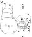
- the section of the Fig. 1 shows the drop profile 3 of an awning which can be moved out of a winding space 21 and moved in again over a roof glass surface 2.
- the drop profile 3 is guided in rails 19 parallel to the roof glass surface 2.
- the movement of the drop profile 3 is indicated by the double arrow 9, which runs parallel to the glass surface 2.
- the body 1 of the cleaning device is fastened to the drop profile 3 via a carrier 5.
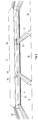
- the carrier 5 extends according to Fig. 2 together with the body 1 over the entire width of the respective roof glass surface 2.
- a U-shaped outer profile 10 is fastened with its back on its underside directed towards the glass surface 2, and a further U-shaped inner profile 11 is attached to the interior thereof its back to the glass surface 2 and is movably held therein.
- Brush rails 4 are arranged on the respective outer edges of the profile 11 on the rear side of the U-inner profile 11 facing the glass surface 2, the free brush ends of which are held just above the glass pane 2 in the case of the inactive cleaning system.
- the U inner profile 11 can be moved from the U outer profile 10 to the glass surface 2. According to the double arrow 20 shown, the brushes 4 come into contact with or float above the glass surface 2. This movement is brought about by the water hose 6, which when filled with the pressurized Cleaning water 8 enlarged in diameter.
- the return springs 14 designed as tension springs, which are aligned in the interior of the profiles 10, 11 parallel to the alignment of the two flanks of the respective U-profile 10, 11 and on the profiles 10, 11 accordingly are attached, the inner profile 11 is displaced in the direction of the glass pane 2, and the brushes 4 are brought into contact with the glass surface 2 to be cleaned.
- the washing water 8 flows in the direction of the water outlet openings 7 provided in the hose 6 and through water passage openings 13 fitting in the U-inner profile 11 against the glass surface 2 and flushes the loosened dirt away from the glass surface 2.
- the water pressure in the water hose 6 is released again, the diameter of the hose 6 decreases, the U-inner profile 11 moves with the aid of the tension springs 14 in the opposite direction to the arrangement on the glass pane, and the cleaning process is ended. So that the U inner profile 11 mounted in the U outer profile 10 is guided during the up and down movement, the U outer profile 10 has elongated holes 12 in the side walls and the U inner profile 11 has thorns 15.
- Consists of a conservatory construction usually consisting of several sections 16 arranged next to one another, which are separated from one another by rafters 17 which are raised relative to the glass surfaces 2.
- a separate body 1 is then attached to the drop profile 3 of the awning for each of the roof glass surfaces, and the hose 6 is connected via a connecting tube 18 via the rafters 17.
- the entire roof of a winter garden is cleaned at the same time by moving the awning in and out several times, if necessary, only by opening the tap. The cleaning is wear-free with the exception that the brushes 4 may be replaced at times.
Landscapes
- Engineering & Computer Science (AREA)
- Architecture (AREA)
- Civil Engineering (AREA)
- Structural Engineering (AREA)
- Chemical & Material Sciences (AREA)
- Chemical Kinetics & Catalysis (AREA)
- Electrochemistry (AREA)
- Mechanical Engineering (AREA)
- Cleaning In General (AREA)
Description
- Die Neuerung bezieht sich auf ein Reinigungssystem für die Glasflächen z. B. eines Wintergartens oder auch Solarpaneelen und Fotovoltaikelementen. Derartige Glasflächen sind der Umwelt direkt ausgesetzt, sie verschmutzen durch Niederschläge aus der Luft, aber auch durch Blätter von Bäumen oder Abfälle von Vögeln. Da die Glasflächen normalerweise durchsichtig sind, stört der sich ablagernde Dreck erheblich, eine Säuberung ist aber nur schwer möglich. Bei Solarsystemen vermindert sich der Wirkungsgrad. Die Schwierigkeit des Säuberns liegt einerseits an der Dachkonstruktion, die zumindest teilweise nicht für das Betreten von einem Menschen ausgelegt ist, oder es ist für den Putzer auf der geneigten, stets glatten Glasfläche zu rutschig. Deshalb ist die sich immer mehr verschmutzende Glasfläche ein ständiges Ärgernis von dem ansonsten sehr nützlichen Wintergarten oder sonstigen Sonnensystemen.
- Die Veröffentlichungsschrift
DE 30 12 576 A1 offenbart eine Reinigungsvorrichtung für Fenster, vor denen ein parallel dazu verschiebbarer, in Führungselementen geführter Rolladen angeordnet ist. Die Reinigungsvorrichtung ist mit dem Rolladen verbunden, so dass durch die Öffnungs- und Schliessbewegung des Rolladens gleichzeitig die Reinigung des Fensters bewirkt wird. Am freien Ende des Rolladens ist ein Reinigungssteg angeordnet, in dem ein, die Oberfläche des Fensters berührendes, befeuchtbares Reinigungselement gelagert ist. Im Weiteren ist im Reinigungssteg ein auf das Reinigungselement einwirkendes, elastisches Andrückelement vorgesehen, welches das Reinigungselement gegen die Oberfläche drückt. - Die Veröffentlichungsschrift
DE 20 2007 014040 U1 offenbart eine Reinigungsvorrichtung für Fenster, die aus einem zu reinigenden Fensterelement und einem in Bezug auf das Fensterelement relativ zu diesem beweglichen Rollladenelement besteht. Das Rollladenelement umfasst über die Breite des Fensterelements eine Düsenleiste mit Düsen, wobei die Düsen in fluidmässiger Verbindung mit einem externen Fluidtank stehen und über eine Steuerungseinrichtung Fluid aus dem Fluidtank über die Düsen auf das Fensterelement gelangt. - Der Neuerung liegt die Aufgabe zugrunde, ein System zu entwickeln, mit dem die Glasfläche z. B. eines Wintergartens einfach und ohne Betreten der Glasfläche selbsttätig zu reinigen ist.
- Die prinzipielle Lösung besteht darin, dass z. B. an der Wintergarten-Glaskonstruktion des Daches im Bereich einer schräg nach unten verlaufenden Dachglasfläche eine Reinigungsvorrichtung befestigt ist, die eine selbsttätige Reinigung ermöglicht. Die Reinigungsvorrichtung muss sich zum Säubern über die Glasfläche bewegen. Deshalb ist es vorteilhaft, wenn die Reinigungsvorrichtung an einem beweglichen Teil wie z. B. einer Markise befestigt ist. Im Prinzip ist an einer normalen Wintergartenkonstruktion oberhalb der Dachglasfläche eine in Schienen geführte Markise angeordnet. Deshalb sollte diese Reinigungsvorrichtung an dem Ausfallprofil der Markise über einen Träger fest verbunden sein. Beim Ausfallen und auch beim wieder Einfahren der Markise erfolgt dann die Reinigung der Dachglasfläche.
- Die Reinigungsvorrichtung besteht aus einer vorteilhaften Konstruktion, nämlich aus einem sich quer über die Glasfläche erstreckenden Korpus, der mit Bürsten und mit einer Wasserzufuhr versehen ist. Selbsttätig arbeitet sie insbesondere dann, wenn durch die Steuerung der Wasserzufuhr in den Korpus die Bürsten Kontakt mit der Glasfläche bekommen und dann mit der funktionsnormalen Auf- und Abbewegung der Markise die Glasfläche reinigen.
- Zusammenfassend betrifft die Erfindung ein Reinigungssystem zum Reinigen von Dachglasflächen, z. B. eines Wintergartens.
- An der Glasflächenkonstruktion ist eine Reinigungsvorrichtung vorgesehen, die selbsttätig eine schräg nach unten verlaufende Glasfläche säubert.
- Die Reinigungsvorrichtung kann an einem beweglichen Teil der Glasflächenkonstruktion befestigt sein.
- Das Reinigungssystem kann an einem Wintergarten vorgesehen sein, welcher eine Markise mit einem die Dachglasfläche zeitweise überfahrbaren Ausfallprofil enthält, wobei die Reinigungsvorrichtung am Ausfallprofil der Markise befestigt ist.
- Das Ausfallprofil kann als Rohr ausgebildet sein.
- Die Reinigungsvorrichtung kann aus einem Korpus bestehen, welcher mit gegen die Dachglasfläche eines Wintergartendaches gerichteten Bürsten versehen ist, wobei der Korpus über einen Träger mit dem Ausfallprofil fest verbunden ist.
- Im Korpus kann ein mit Frischwasser zu versorgender Wasserschlauch vorgesehen sein.
- Der Wasserschlauch kann über seine Länge mit mehreren gegen die Dachglasfläche des Wintergartens gerichteten Wasseraustrittsöffnungen versehen sein.
- Der Wasserschlauch kann sich parallel zu den gegen die Dachglasfläche gerichteten Bürsten erstrecken.
- Die Bürsten können in Bewegungsrichtung der Markise zeitweilig mit der Dachglasfläche in Kontakt gebracht werden.
- Die Bürsten können zusätzlich längs ihrer Erstreckung bewegbar sein.
- Die Bürsten können in Rotation flächig über die Glasfläche in Bewegung versetzbar sein.
- Der Korpus kann aus einem zur Glasfläche offenen und rückseitig mit einem Träger verbundenen U-Außenprofil bestehen, in dem ein zweites, schmaleres mit dem Rücken zur Glasfläche ausgerichtetes U-Innenprofil zur Glasfläche hin längs geführt bewegbar gehalten ist.
- Das U-Innenprofil kann mittels in dem U-Außenprofil vorgesehenen Langloch und passend an dem U-Innenprofil vorgesehenen Führungsbolzen zur Glasfläche hin längs geführt bewegbar gehalten sein.
- An der gegen die Dachglasfläche gerichteten Außenfläche des U-Innenprofils können die Bürsten längs befestigt sein.
- Längs der beiden Außenkanten des U-Innenprofils können die Bürsten an diesem befestigt sein.
- Der Rücken des U-Innenprofils kann mit Wasserdurchtrittsöffnungen versehen sein.
- Der Rücken kann im Bereich zwischen den Bürsten mit Wasserdurchtrittsöffnungen versehen sein.
- Der Wasserschlauch erstreckt sich sich in dem von dem U-Innenprofil und U-Außenprofil gebildeten Raum längs.
- Der Wasserschlauch besteht aus einem sich im Durchmesser in Abhängigkeit des Wasserdrucks verändernden Druckwasserschlauchs.
- Das U-Innenprofil und damit die Bürsten sind in Abhängigkeit des Wasserdrucks in dem Wasserschlauch gegen die Glasfläche bewegbar.
- Der sich verändernde Wasserdruck in dem Wasserschlauch kann den Austritt des Wassers aus den sich weitenden Wasseraustrittöffnungen am Wasserschlauch und gleichzeitig die Bewegung des U-Innenprofils gegen die Dachglasfläche und damit den Kontakt der Bürsten mit der Dachglasfläche bewirken.
- Das U-Innenprofil kann über am U-Innenprofil befestigte Zugfedern auch gegen den Druck von dem unter Druck stehenden Wasserschlauch an dem U-Außenprofil gehalten sein.
- Beim Stoppen des Wasserzuflusses in den im Durchmesser sich damit verkleinernden Wasserschlauch kann durch die Wirkung der als Rückholfedern vorgesehenen Zugfedern das U-Innenprofil in das U-Außenprofil anhebbar und damit die Bürsten von der Dachglasfläche weg bewegbar sein.
- Das Reinigungssystem kann an einem Wintergarten mit mehreren Sektionen und damit mehreren Dachglasflächen, die durch Sparren voneinander getrennt sind, vorgesehen sein, wobei für jede der Dachglasflächen ein gesonderter Korpus an dem Ausfallprofil befestigt ist und die längs über die ganze Breite des Wintergartendaches sich erstreckenden Druckwasserschläuche über die Sparren mit einem Verbindungsrohr versehen sind.
- In der Zeichnung ist die Neuerung beispielhaft anhand eines Wintergartens im Einzelnen dargestellt. Es zeigen:
- Fig. 1
- einen Querschnitt durch die Reinigungsvorrichtung parallel zur Bewegungsrichtung der Markise und
- Fig. 2
- die Draufsicht auf die Stirnseite der Dachglaskonstruktion mit mehreren Sektionen und sichtbarer Reinigungsvorrichtung über alle der Dachglasflächen.
- Der Ausschnitt der
Fig. 1 zeigt das Ausfallprofil 3 einer aus einem Aufwickelraum 21 raus- und wieder rein bewegbaren Markise über einer Dachglasfläche 2. Das Ausfallprofil 3 ist in Schienen 19 parallel zur Dachglasfläche 2 geführt. Die Bewegung des Ausfallprofils 3 ist mit dem Doppelpfeil 9 angedeutet, die parallel zur Glasfläche 2 verläuft. An dem Ausfallprofil 3 ist über einen Träger 5 der Korpus 1 der Reinigungsvorrichtung befestigt. Der Träger 5 erstreckt sich gemäßFig. 2 zusammen mit dem Korpus 1 über die ganze Breite der jeweiligen Dachglasfläche 2. Am freien Ende des Trägers 5 ist auf seiner zur Glasfläche 2 gerichteten Unterseite ein U-förmiges Außenprofil 10 mit seiner Rückseite befestigt, in dessen Innenraum ein weiteres U-förmiges Innenprofil 11 mit seiner Rückseite zur Glasfläche 2 eingeschoben und darin beweglich gehalten ist. Durch diese beiden ineinandergreifenden U-förmigen Profile 10, 11 ist ein Hohlraum entstanden, in dem sich ein Wasserschlauch 6 längs erstreckt. - Auf der zur Glasfläche 2 gerichteten Rückseite des U-Innenprofils 11 sind an den jeweiligen Außenkanten des Profils 11 Bürstenschienen 4 angeordnet, deren freie Bürstenenden im Falle des nicht aktiven Reinigungssystems kurz oberhalb der Glasscheibe 2 gehalten sind.
- Das U-Innenprofil 11 ist aus dem U-Außenprofil 10 zur Glasfläche 2 bewegbar. Gemäß dem dargestellten Doppelpfeil 20 gelangen die Bürsten 4 mit der Glasfläche 2 in Kontakt oder schweben darüber. Diese Bewegung wird herbeigeführt durch den Wasserschlauch 6, der sich beim Füllen mit dem unter Druck stehenden Reinigungswasser 8 im Durchmesser vergrößert. Durch die Vergrößerung des Durchmessers des Schlauches 6 wird gegen die Kraft der als Zugfedern ausgebildeten Rückholfedern 14, die im Innenraum der Profile 10, 11 parallel zur Ausrichtung der beiden Flanken des jeweiligen U-Profils 10, 11 ausgerichtet und an den Profilen 10, 11 entsprechend befestigt sind, das Innenprofil 11 in Richtung der Glasscheibe 2 verschoben, und die Bürsten 4 werden mit der zu reinigenden Glasfläche 2 in Kontakt gebracht. Gleichzeitig fließt das Waschwasser 8 durch in Richtung der in dem Schlauch 6 vorgesehenen Wasseraustrittsöffnungen 7 und durch in dem U-Innenprofil 11 passende Wasserdurchtrittsöffnungen 13 gegen die Glasfläche 2 und schwemmt die gelösten Verschmutzungen von der Glasfläche 2 weg. Beim Beenden der Reinigungsvorganges wird der Wasserdruck im Wasserschlauch 6 wieder aufgehoben, der Durchmesser des Schlauches 6 verringert sich, das U-Innenprofil 11 bewegt sich unter Hilfe der Zugfedern 14 entgegengesetzt zur Anordnung an der Glasscheibe, und der Reinigungsvorgang ist beendet. Damit das in dem U-Außenprofil 10 gelagerte U-Innenprofil 11 bei der Bewegung Auf und Ab geführt ist, weist das U-Außenprofil 10 in den Seitenwangen Langlöcher 12 und das U-Innenprofil 11 Dornen 15 auf.
- Gemäß
Fig. 2 besteht eine Wintergartenkonstruktion üblicherweise aus mehreren nebeneinander angeordneten Sektionen 16, die durch gegenüber den Glasflächen 2 erhöhte Sparren 17 voneinander getrennt sind. Für jede der Dachglasflächen ist dann ein gesonderter Korpus 1 an dem Ausfallprofil 3 der Markise befestigt, und der Schlauch 6 ist über ein Verbindungsrohr 18 über die Sparren 17 hinweg verbunden. Auf diese Weise wird das ganze Dach eines Wintergartens zur gleichen Zeit durch ggf. mehrfaches Ein- und Ausfahrbewegen der Markise nur durch Öffnen des Wasserhahnes gereinigt. Die Reinigung erfolgt verschleiß frei mit Ausnahme, dass ggf. bei Zeiten die Bürsten 4 ersetzt werden.
Claims (18)
- Reinigungssystem zur Reinigung von Dachglasflächen (2) einer Glasflächenkonstruktion, enthaltend eine Reinigungsvorrichtung, welche an die Glasflächenkonstruktion anbringbar und dazu ausgelegt ist, selbsttätig eine schräg nach unten verlaufende Dachglasfläche (2) zu säubern, wobei
die Reinigungsvorrichtung an einem beweglichen Teil befestigt ist, und
die Reinigungsvorrichtung zum Säubern über die Dachglasfläche bewegbar ist, und
die Reinigungsvorrichtung einen sich quer über die Dachglasfläche (2) erstreckenden Korpus (1) enthält, welcher mit Bürsten (4) und einer Wasserzufuhr versehen ist,
dadurch gekennzeichnet, dass
der Korpus (1) aus einem zur Dachglasfläche (2) offenen und rückseitig mit einem Träger (5) verbundenen U-Außenprofil (10) besteht, und im Korpus (1) ein zweites, schmaleres mit dem Rücken zur Dachglasfläche (2) ausgerichtetes U-Innenprofil (11) zur Dachglasfläche (2) hin geführt bewegbar gehalten ist, und an der gegen die Dachglasfläche (2) gerichteten Außenfläche des Rückens des U-Innenprofils (11) die Bürsten (4) längs befestigt sind, und
die Reinigungsvorrichtung einen mit Frischwasser versorgbaren Wasserschlauch (6) umfasst, welcher sich in dem von dem U-Innenprofil (11) und U-Außenprofil (10) gebildeten Raum längs erstreckt, und
der Wasserschlauch (6) aus einem sich im Durchmesser in Abhängigkeit des Wasserdrucks verändernden Druckwasserschlauch besteht, und
in Abhängigkeit des Wasserdrucks in dem Wasserschlauch (6) das U-Innenprofil (11) und damit die Bürsten (4) gegen die Dachglasfläche (2) bewegbar ist. - Reinigungssystem nach Anspruch 1, dadurch gekennzeichnet, dass das bewegliche Teil eine Markise ist.
- Reinigungssystem nach Anspruch 2, dadurch gekennzeichnet, dass die Markise ein die Dachglasfläche (2) zeitweise überfahrbares Ausfallprofil (3) enthält, wobei die Reinigungsvorrichtung an dem Ausfallprofil (3) der Markise befestigt ist.
- Reinigungssystem nach Anspruch 3, dadurch gekennzeichnet, dass das Ausfallprofil (3) als Rohr ausgebildet ist.
- Reinigungssystem nach Anspruch 3 oder 4, dadurch gekennzeichnet, dass die Reinigungsvorrichtung einen Korpus (1) mit gegen eine Dachglasfläche (2) eines Wintergartendaches richtbaren Bürsten (4) umfasst, wobei der Korpus (1) mit dem Ausfallprofil (3) über einen Träger (5) fest verbunden ist.
- Reinigungssystem nach einem der Ansprüche 1 bis 5, dadurch gekennzeichnet, dass der Wasserschlauch (6) über seine Länge mit mehreren gegen die Dachglasfläche (2) des Wintergartens gerichteten Wasseraustrittöffnungen (7) versehen ist.
- Reinigungssystem nach Anspruch 1 bis 6, dadurch gekennzeichnet, dass der Wasserschlauch (6) sich parallel zu den gegen die Dachglasfläche (2) gerichteten Bürsten (4) erstreckt.
- Reinigungssystem nach einem oder mehreren der Ansprüche 2 bis 7, dadurch gekennzeichnet, dass die Bürsten (4) in Bewegungsrichtung (9) der Markise mit der Dachglasfläche (2) zeitweilig in Kontakt bringbar sind.
- Reinigungssystem nach Anspruch 8, dadurch gekennzeichnet, dass die Bürsten (4) zusätzlich längs ihrer Erstreckung bewegbar sind.
- Reinigungssystem nach Anspruch 8 oder 9, dadurch gekennzeichnet, dass die Bürsten (4) flächig über der Dachglasfläche (2) in eine Rotations-Bewegung versetzbar sind.
- Reinigungssystem nach Anspruch 1, dadurch gekennzeichnet, dass das U-Innenprofil (11) mittels im U-Außenprofil (10) vorgesehenen Langloch (12) und passend an dem U-Innenprofil (11) vorgesehenen Führungsbolzen (15) zur Dachglasfläche (2) hin geführt bewegbar im Korpus (1) gehalten ist.
- Reinigungssystem nach einem der Ansprüche 1 bis 11, dadurch gekennzeichnet, dass die Bürsten (4) längs der beiden Außenkanten des U-Innenprofils (11) am U-Innenprofil (11) befestigt sind.
- Reinigungssystem nach Anspruch 12 oder 13, dadurch gekennzeichnet, dass der Rücken des U-Innenprofils (11) mit Wasserdurchtrittsöffnungen (13) versehen ist.
- Reinigungssystem nach Anspruch 13, dadurch gekennzeichnet, dass die Wasserdurchtrittsöffnungen (13) im Bereich zwischen den Bürsten (4) vorgesehen sind.
- Reinigungssystem nach einem der Ansprüche 1 bis 14, dadurch gekennzeichnet, dass die Reinigungsvorrichtung so ausgelegt ist, dass der sich verändernde Wasserdruck in dem Wasserschlauch (6) den Austritt des Wassers aus den sich weitenden Wasseraustrittöffnungen (7) am Wasserschlauch (6) und gleichzeitig die Bewegung des U-Innenprofils (11) gegen die Dachglasfläche (2) und damit den Kontakt der Bürsten (4) mit der Dachglasfläche (2) bewirkt.
- Reinigungssystem nach einem der Ansprüche 1 bis 15, dadurch gekennzeichnet, dass das U-Innenprofil (11) über am U-Innenprofil (11) befestigte Zugfedern (14) auch gegen den Druck von dem unter Druck stehenden Wasserschlauch (6) an dem U-Außenprofil (10) gehalten ist.
- Reinigungssystem nach Anspruch 16, dadurch gekennzeichnet, dass die Reinigungsvorrichtung so ausgelegt ist, dass beim Stoppen des Wasserzuflusses in den im Durchmesser sich damit verkleinernden Wasserschlauch (6) durch die Wirkung der die Funktion von Rückholfedern ausübenden Zugfedern (14) das U-Innenprofil (11) in das U-Außenprofil (10) anhebbar ist und damit die Bürsten (4) von der Dachglasfläche (2) weg bewegbar sind.
- Wintergarten mit einem Reinigungssystem nach einem der Ansprüche 1 bis 17.
Applications Claiming Priority (2)
| Application Number | Priority Date | Filing Date | Title |
|---|---|---|---|
| DE202013003127 | 2013-04-03 | ||
| DE202013004614U DE202013004614U1 (de) | 2013-04-03 | 2013-05-16 | Reinigungssystem für Dachglasflächen |
Publications (3)
| Publication Number | Publication Date |
|---|---|
| EP2787134A2 EP2787134A2 (de) | 2014-10-08 |
| EP2787134A3 EP2787134A3 (de) | 2017-05-10 |
| EP2787134B1 true EP2787134B1 (de) | 2020-04-08 |
Family
ID=48868603
Family Applications (1)
| Application Number | Title | Priority Date | Filing Date |
|---|---|---|---|
| EP13004522.2A Active EP2787134B1 (de) | 2013-04-03 | 2013-09-13 | Reinigungssystem für Glasflächen |
Country Status (2)
| Country | Link |
|---|---|
| EP (1) | EP2787134B1 (de) |
| DE (1) | DE202013004614U1 (de) |
Families Citing this family (2)
| Publication number | Priority date | Publication date | Assignee | Title |
|---|---|---|---|---|
| DE202016103889U1 (de) | 2016-07-18 | 2016-08-12 | Albert Doejen | Reinigungsvorrichtung für Terrassenüberdachungen an einem Gebäude |
| CN111643015B (zh) * | 2020-06-15 | 2025-02-14 | 南昌大学 | 一种用于清洗墙面的滚轮刷 |
Family Cites Families (2)
| Publication number | Priority date | Publication date | Assignee | Title |
|---|---|---|---|---|
| DE3012576A1 (de) * | 1980-04-01 | 1981-10-08 | Erwin 7443 Frickenhausen Noizet | Reinigungsvorrichtung fuer fenster |
| DE202007014040U1 (de) * | 2007-10-08 | 2007-12-27 | Geist, Peter | Reinigungsvorrichtung für Fenster |
-
2013
- 2013-05-16 DE DE202013004614U patent/DE202013004614U1/de not_active Expired - Lifetime
- 2013-09-13 EP EP13004522.2A patent/EP2787134B1/de active Active
Non-Patent Citations (1)
| Title |
|---|
| None * |
Also Published As
| Publication number | Publication date |
|---|---|
| EP2787134A2 (de) | 2014-10-08 |
| EP2787134A3 (de) | 2017-05-10 |
| DE202013004614U1 (de) | 2013-06-25 |
Similar Documents
| Publication | Publication Date | Title |
|---|---|---|
| EP3272968B1 (de) | Reinigungsvorrichtung für terrassenüberdachungen an einem gebäude | |
| DE202007006491U1 (de) | Waschanlage | |
| DE202006003697U1 (de) | Vorrichtung zur Reinigung von Solarzellen | |
| EP2787134B1 (de) | Reinigungssystem für Glasflächen | |
| DE102008022270A1 (de) | Wintergartenmarkise und Reinigungseinrichtung für eine Wintergartenverglasung | |
| DE2136197B2 (de) | Vorrichtung für die Abluftreinigung einer Fabrikhalle | |
| EP3626905B1 (de) | Glasdach-reinigungssystem | |
| DE202021104050U1 (de) | Automatisierte Reinigungsvorrichtung für geneigte Glasdächer, wie Glasdächer von Wintergärten | |
| EP3604704A1 (de) | Überdachung mit optimierter regenwasserführung | |
| DE10049325C2 (de) | Vorrichtung zum Reinigen von Sonnenschutzanlagen | |
| DE19617665C2 (de) | Feststoff-Rückhaltevorrichtung für Regenüberlaufbauwerke | |
| DE202007014040U1 (de) | Reinigungsvorrichtung für Fenster | |
| DE102019115584A1 (de) | Schräg in einen offenen Kanal aufstellbare Rechenanlage | |
| DE102006059961A1 (de) | Festinstallierte automatische Reinigungsanlage für waagrechte und geneigte Fensteraußenflächen, insbesondere denen von Wintergärten und Dachfenstern | |
| DE102004034819B3 (de) | Transportable Reinigungsvorrichtung | |
| DE19831474A1 (de) | Vorrichtung zur Reinigung von Dachrinnen | |
| EP0393008A2 (de) | Vorrichtung zum Reinigen und Trocknen von Glastafeln | |
| DE102022001005A1 (de) | Reinigungseinrichtung und Verfahren zur Verwendung einer Reinigungseinrichtung | |
| WO2008138767A1 (de) | Vorrichtung zum behandeln, bearbeiten und/oder reinigen von oberflächen | |
| DE19834519A1 (de) | Zwei- oder mehrschaliges Gebäudeteil | |
| AT517283A1 (de) | Duschabtrennung mit Schiebetüre und Führungselement | |
| DE19501953C2 (de) | Vorrichtung zum Absperren eines durch einen als rostartiges Stabwerk ausgebildeten Rechen zum Zurückhalten sperrigen Treibguts geführten Wasserzulaufs zu einer Wasserturbine oder einer Abwasserbehandlungsanlage | |
| EP1618965A2 (de) | Vorrichtung für einen Farbwechsel beim Aufbringen eines über die Arbeitsbreite gleichmässig dünnen Flüssigkeitsfilmes auf eine Warenbahn | |
| DE102014115878B4 (de) | Abwasserentsorgungsrinne | |
| DE202006005905U1 (de) | Jalousie |
Legal Events
| Date | Code | Title | Description |
|---|---|---|---|
| PUAI | Public reference made under article 153(3) epc to a published international application that has entered the european phase |
Free format text: ORIGINAL CODE: 0009012 |
|
| 17P | Request for examination filed |
Effective date: 20130913 |
|
| AK | Designated contracting states |
Kind code of ref document: A2 Designated state(s): AL AT BE BG CH CY CZ DE DK EE ES FI FR GB GR HR HU IE IS IT LI LT LU LV MC MK MT NL NO PL PT RO RS SE SI SK SM TR |
|
| AX | Request for extension of the european patent |
Extension state: BA ME |
|
| RAP1 | Party data changed (applicant data changed or rights of an application transferred) |
Owner name: GU. T. FINANZ AG |
|
| RIN1 | Information on inventor provided before grant (corrected) |
Inventor name: GU. T. FINANZ AG |
|
| PUAL | Search report despatched |
Free format text: ORIGINAL CODE: 0009013 |
|
| AK | Designated contracting states |
Kind code of ref document: A3 Designated state(s): AL AT BE BG CH CY CZ DE DK EE ES FI FR GB GR HR HU IE IS IT LI LT LU LV MC MK MT NL NO PL PT RO RS SE SI SK SM TR |
|
| AX | Request for extension of the european patent |
Extension state: BA ME |
|
| RIC1 | Information provided on ipc code assigned before grant |
Ipc: E04B 1/00 20060101AFI20170404BHEP Ipc: A47L 1/02 20060101ALI20170404BHEP Ipc: E04F 10/06 20060101ALI20170404BHEP |
|
| STAA | Information on the status of an ep patent application or granted ep patent |
Free format text: STATUS: REQUEST FOR EXAMINATION WAS MADE |
|
| R17P | Request for examination filed (corrected) |
Effective date: 20171107 |
|
| RBV | Designated contracting states (corrected) |
Designated state(s): AL AT BE BG CH CY CZ DE DK EE ES FI FR GB GR HR HU IE IS IT LI LT LU LV MC MK MT NL NO PL PT RO RS SE SI SK SM TR |
|
| STAA | Information on the status of an ep patent application or granted ep patent |
Free format text: STATUS: EXAMINATION IS IN PROGRESS |
|
| 17Q | First examination report despatched |
Effective date: 20181121 |
|
| GRAP | Despatch of communication of intention to grant a patent |
Free format text: ORIGINAL CODE: EPIDOSNIGR1 |
|
| STAA | Information on the status of an ep patent application or granted ep patent |
Free format text: STATUS: GRANT OF PATENT IS INTENDED |
|
| INTG | Intention to grant announced |
Effective date: 20191016 |
|
| GRAS | Grant fee paid |
Free format text: ORIGINAL CODE: EPIDOSNIGR3 |
|
| GRAA | (expected) grant |
Free format text: ORIGINAL CODE: 0009210 |
|
| STAA | Information on the status of an ep patent application or granted ep patent |
Free format text: STATUS: THE PATENT HAS BEEN GRANTED |
|
| RIN1 | Information on inventor provided before grant (corrected) |
Inventor name: ZAPPOLD, WOLFGANG |
|
| AK | Designated contracting states |
Kind code of ref document: B1 Designated state(s): AL AT BE BG CH CY CZ DE DK EE ES FI FR GB GR HR HU IE IS IT LI LT LU LV MC MK MT NL NO PL PT RO RS SE SI SK SM TR |
|
| REG | Reference to a national code |
Ref country code: CH Ref legal event code: EP Ref country code: AT Ref legal event code: REF Ref document number: 1254565 Country of ref document: AT Kind code of ref document: T Effective date: 20200415 |
|
| REG | Reference to a national code |
Ref country code: DE Ref legal event code: R096 Ref document number: 502013014544 Country of ref document: DE |
|
| REG | Reference to a national code |
Ref country code: IE Ref legal event code: FG4D Free format text: LANGUAGE OF EP DOCUMENT: GERMAN |
|
| REG | Reference to a national code |
Ref country code: CH Ref legal event code: NV Representative=s name: FREI PATENTANWALTSBUERO AG, CH |
|
| REG | Reference to a national code |
Ref country code: NL Ref legal event code: MP Effective date: 20200408 |
|
| REG | Reference to a national code |
Ref country code: LT Ref legal event code: MG4D |
|
| PG25 | Lapsed in a contracting state [announced via postgrant information from national office to epo] |
Ref country code: LT Free format text: LAPSE BECAUSE OF FAILURE TO SUBMIT A TRANSLATION OF THE DESCRIPTION OR TO PAY THE FEE WITHIN THE PRESCRIBED TIME-LIMIT Effective date: 20200408 Ref country code: NL Free format text: LAPSE BECAUSE OF FAILURE TO SUBMIT A TRANSLATION OF THE DESCRIPTION OR TO PAY THE FEE WITHIN THE PRESCRIBED TIME-LIMIT Effective date: 20200408 Ref country code: PT Free format text: LAPSE BECAUSE OF FAILURE TO SUBMIT A TRANSLATION OF THE DESCRIPTION OR TO PAY THE FEE WITHIN THE PRESCRIBED TIME-LIMIT Effective date: 20200817 Ref country code: FI Free format text: LAPSE BECAUSE OF FAILURE TO SUBMIT A TRANSLATION OF THE DESCRIPTION OR TO PAY THE FEE WITHIN THE PRESCRIBED TIME-LIMIT Effective date: 20200408 Ref country code: NO Free format text: LAPSE BECAUSE OF FAILURE TO SUBMIT A TRANSLATION OF THE DESCRIPTION OR TO PAY THE FEE WITHIN THE PRESCRIBED TIME-LIMIT Effective date: 20200708 Ref country code: GR Free format text: LAPSE BECAUSE OF FAILURE TO SUBMIT A TRANSLATION OF THE DESCRIPTION OR TO PAY THE FEE WITHIN THE PRESCRIBED TIME-LIMIT Effective date: 20200709 Ref country code: SE Free format text: LAPSE BECAUSE OF FAILURE TO SUBMIT A TRANSLATION OF THE DESCRIPTION OR TO PAY THE FEE WITHIN THE PRESCRIBED TIME-LIMIT Effective date: 20200408 Ref country code: IS Free format text: LAPSE BECAUSE OF FAILURE TO SUBMIT A TRANSLATION OF THE DESCRIPTION OR TO PAY THE FEE WITHIN THE PRESCRIBED TIME-LIMIT Effective date: 20200808 |
|
| PG25 | Lapsed in a contracting state [announced via postgrant information from national office to epo] |
Ref country code: LV Free format text: LAPSE BECAUSE OF FAILURE TO SUBMIT A TRANSLATION OF THE DESCRIPTION OR TO PAY THE FEE WITHIN THE PRESCRIBED TIME-LIMIT Effective date: 20200408 Ref country code: RS Free format text: LAPSE BECAUSE OF FAILURE TO SUBMIT A TRANSLATION OF THE DESCRIPTION OR TO PAY THE FEE WITHIN THE PRESCRIBED TIME-LIMIT Effective date: 20200408 Ref country code: HR Free format text: LAPSE BECAUSE OF FAILURE TO SUBMIT A TRANSLATION OF THE DESCRIPTION OR TO PAY THE FEE WITHIN THE PRESCRIBED TIME-LIMIT Effective date: 20200408 Ref country code: BG Free format text: LAPSE BECAUSE OF FAILURE TO SUBMIT A TRANSLATION OF THE DESCRIPTION OR TO PAY THE FEE WITHIN THE PRESCRIBED TIME-LIMIT Effective date: 20200708 |
|
| PG25 | Lapsed in a contracting state [announced via postgrant information from national office to epo] |
Ref country code: AL Free format text: LAPSE BECAUSE OF FAILURE TO SUBMIT A TRANSLATION OF THE DESCRIPTION OR TO PAY THE FEE WITHIN THE PRESCRIBED TIME-LIMIT Effective date: 20200408 |
|
| REG | Reference to a national code |
Ref country code: DE Ref legal event code: R097 Ref document number: 502013014544 Country of ref document: DE |
|
| PG25 | Lapsed in a contracting state [announced via postgrant information from national office to epo] |
Ref country code: IT Free format text: LAPSE BECAUSE OF FAILURE TO SUBMIT A TRANSLATION OF THE DESCRIPTION OR TO PAY THE FEE WITHIN THE PRESCRIBED TIME-LIMIT Effective date: 20200408 Ref country code: ES Free format text: LAPSE BECAUSE OF FAILURE TO SUBMIT A TRANSLATION OF THE DESCRIPTION OR TO PAY THE FEE WITHIN THE PRESCRIBED TIME-LIMIT Effective date: 20200408 Ref country code: RO Free format text: LAPSE BECAUSE OF FAILURE TO SUBMIT A TRANSLATION OF THE DESCRIPTION OR TO PAY THE FEE WITHIN THE PRESCRIBED TIME-LIMIT Effective date: 20200408 Ref country code: CZ Free format text: LAPSE BECAUSE OF FAILURE TO SUBMIT A TRANSLATION OF THE DESCRIPTION OR TO PAY THE FEE WITHIN THE PRESCRIBED TIME-LIMIT Effective date: 20200408 Ref country code: DK Free format text: LAPSE BECAUSE OF FAILURE TO SUBMIT A TRANSLATION OF THE DESCRIPTION OR TO PAY THE FEE WITHIN THE PRESCRIBED TIME-LIMIT Effective date: 20200408 Ref country code: SM Free format text: LAPSE BECAUSE OF FAILURE TO SUBMIT A TRANSLATION OF THE DESCRIPTION OR TO PAY THE FEE WITHIN THE PRESCRIBED TIME-LIMIT Effective date: 20200408 Ref country code: EE Free format text: LAPSE BECAUSE OF FAILURE TO SUBMIT A TRANSLATION OF THE DESCRIPTION OR TO PAY THE FEE WITHIN THE PRESCRIBED TIME-LIMIT Effective date: 20200408 |
|
| PLBE | No opposition filed within time limit |
Free format text: ORIGINAL CODE: 0009261 |
|
| STAA | Information on the status of an ep patent application or granted ep patent |
Free format text: STATUS: NO OPPOSITION FILED WITHIN TIME LIMIT |
|
| PG25 | Lapsed in a contracting state [announced via postgrant information from national office to epo] |
Ref country code: SK Free format text: LAPSE BECAUSE OF FAILURE TO SUBMIT A TRANSLATION OF THE DESCRIPTION OR TO PAY THE FEE WITHIN THE PRESCRIBED TIME-LIMIT Effective date: 20200408 Ref country code: PL Free format text: LAPSE BECAUSE OF FAILURE TO SUBMIT A TRANSLATION OF THE DESCRIPTION OR TO PAY THE FEE WITHIN THE PRESCRIBED TIME-LIMIT Effective date: 20200408 |
|
| 26N | No opposition filed |
Effective date: 20210112 |
|
| PG25 | Lapsed in a contracting state [announced via postgrant information from national office to epo] |
Ref country code: MC Free format text: LAPSE BECAUSE OF FAILURE TO SUBMIT A TRANSLATION OF THE DESCRIPTION OR TO PAY THE FEE WITHIN THE PRESCRIBED TIME-LIMIT Effective date: 20200408 |
|
| GBPC | Gb: european patent ceased through non-payment of renewal fee |
Effective date: 20200913 |
|
| PG25 | Lapsed in a contracting state [announced via postgrant information from national office to epo] |
Ref country code: SI Free format text: LAPSE BECAUSE OF FAILURE TO SUBMIT A TRANSLATION OF THE DESCRIPTION OR TO PAY THE FEE WITHIN THE PRESCRIBED TIME-LIMIT Effective date: 20200408 |
|
| REG | Reference to a national code |
Ref country code: BE Ref legal event code: MM Effective date: 20200930 |
|
| PG25 | Lapsed in a contracting state [announced via postgrant information from national office to epo] |
Ref country code: LU Free format text: LAPSE BECAUSE OF NON-PAYMENT OF DUE FEES Effective date: 20200913 |
|
| PG25 | Lapsed in a contracting state [announced via postgrant information from national office to epo] |
Ref country code: FR Free format text: LAPSE BECAUSE OF NON-PAYMENT OF DUE FEES Effective date: 20200930 |
|
| PG25 | Lapsed in a contracting state [announced via postgrant information from national office to epo] |
Ref country code: IE Free format text: LAPSE BECAUSE OF NON-PAYMENT OF DUE FEES Effective date: 20200913 Ref country code: GB Free format text: LAPSE BECAUSE OF NON-PAYMENT OF DUE FEES Effective date: 20200913 Ref country code: BE Free format text: LAPSE BECAUSE OF NON-PAYMENT OF DUE FEES Effective date: 20200930 |
|
| PG25 | Lapsed in a contracting state [announced via postgrant information from national office to epo] |
Ref country code: TR Free format text: LAPSE BECAUSE OF FAILURE TO SUBMIT A TRANSLATION OF THE DESCRIPTION OR TO PAY THE FEE WITHIN THE PRESCRIBED TIME-LIMIT Effective date: 20200408 Ref country code: MT Free format text: LAPSE BECAUSE OF FAILURE TO SUBMIT A TRANSLATION OF THE DESCRIPTION OR TO PAY THE FEE WITHIN THE PRESCRIBED TIME-LIMIT Effective date: 20200408 Ref country code: CY Free format text: LAPSE BECAUSE OF FAILURE TO SUBMIT A TRANSLATION OF THE DESCRIPTION OR TO PAY THE FEE WITHIN THE PRESCRIBED TIME-LIMIT Effective date: 20200408 |
|
| PG25 | Lapsed in a contracting state [announced via postgrant information from national office to epo] |
Ref country code: MK Free format text: LAPSE BECAUSE OF FAILURE TO SUBMIT A TRANSLATION OF THE DESCRIPTION OR TO PAY THE FEE WITHIN THE PRESCRIBED TIME-LIMIT Effective date: 20200408 |
|
| PGFP | Annual fee paid to national office [announced via postgrant information from national office to epo] |
Ref country code: AT Payment date: 20230921 Year of fee payment: 11 |
|
| PGFP | Annual fee paid to national office [announced via postgrant information from national office to epo] |
Ref country code: DE Payment date: 20230920 Year of fee payment: 11 |
|
| REG | Reference to a national code |
Ref country code: DE Ref legal event code: R119 Ref document number: 502013014544 Country of ref document: DE |
|
| REG | Reference to a national code |
Ref country code: AT Ref legal event code: MM01 Ref document number: 1254565 Country of ref document: AT Kind code of ref document: T Effective date: 20240913 |
|
| PG25 | Lapsed in a contracting state [announced via postgrant information from national office to epo] |
Ref country code: DE Free format text: LAPSE BECAUSE OF NON-PAYMENT OF DUE FEES Effective date: 20250401 |
|
| PG25 | Lapsed in a contracting state [announced via postgrant information from national office to epo] |
Ref country code: AT Free format text: LAPSE BECAUSE OF NON-PAYMENT OF DUE FEES Effective date: 20240913 |
|
| REG | Reference to a national code |
Ref country code: CH Ref legal event code: U11 Free format text: ST27 STATUS EVENT CODE: U-0-0-U10-U11 (AS PROVIDED BY THE NATIONAL OFFICE) Effective date: 20251001 |
|
| PGFP | Annual fee paid to national office [announced via postgrant information from national office to epo] |
Ref country code: CH Payment date: 20251001 Year of fee payment: 13 |