EP2785554B1 - Aggregatsystem und verfahren zum betreiben eines aggregatsystems - Google Patents
Aggregatsystem und verfahren zum betreiben eines aggregatsystems Download PDFInfo
- Publication number
- EP2785554B1 EP2785554B1 EP12791512.2A EP12791512A EP2785554B1 EP 2785554 B1 EP2785554 B1 EP 2785554B1 EP 12791512 A EP12791512 A EP 12791512A EP 2785554 B1 EP2785554 B1 EP 2785554B1
- Authority
- EP
- European Patent Office
- Prior art keywords
- clutch
- drive motor
- oil
- power train
- bearing
- Prior art date
- Legal status (The legal status is an assumption and is not a legal conclusion. Google has not performed a legal analysis and makes no representation as to the accuracy of the status listed.)
- Not-in-force
Links
- 238000000034 method Methods 0.000 title claims description 12
- 230000007935 neutral effect Effects 0.000 claims 2
- 239000003921 oil Substances 0.000 description 119
- 230000008878 coupling Effects 0.000 description 13
- 238000010168 coupling process Methods 0.000 description 13
- 238000005859 coupling reaction Methods 0.000 description 13
- 238000005461 lubrication Methods 0.000 description 13
- 230000000875 corresponding effect Effects 0.000 description 6
- 238000012546 transfer Methods 0.000 description 5
- 230000001419 dependent effect Effects 0.000 description 3
- 238000002360 preparation method Methods 0.000 description 3
- 239000004071 soot Substances 0.000 description 3
- 230000005540 biological transmission Effects 0.000 description 2
- 230000008569 process Effects 0.000 description 2
- 230000015572 biosynthetic process Effects 0.000 description 1
- 230000008859 change Effects 0.000 description 1
- 238000010276 construction Methods 0.000 description 1
- 238000001816 cooling Methods 0.000 description 1
- 230000002596 correlated effect Effects 0.000 description 1
- 230000002950 deficient Effects 0.000 description 1
- 238000001514 detection method Methods 0.000 description 1
- 238000011161 development Methods 0.000 description 1
- 230000018109 developmental process Effects 0.000 description 1
- 238000010353 genetic engineering Methods 0.000 description 1
- 238000012986 modification Methods 0.000 description 1
- 230000004048 modification Effects 0.000 description 1
- 239000010705 motor oil Substances 0.000 description 1
- 238000013021 overheating Methods 0.000 description 1
- 238000012545 processing Methods 0.000 description 1
- 230000008929 regeneration Effects 0.000 description 1
- 238000011069 regeneration method Methods 0.000 description 1
- 230000003068 static effect Effects 0.000 description 1
- 238000011144 upstream manufacturing Methods 0.000 description 1
Images



Classifications
-
- B—PERFORMING OPERATIONS; TRANSPORTING
- B60—VEHICLES IN GENERAL
- B60K—ARRANGEMENT OR MOUNTING OF PROPULSION UNITS OR OF TRANSMISSIONS IN VEHICLES; ARRANGEMENT OR MOUNTING OF PLURAL DIVERSE PRIME-MOVERS IN VEHICLES; AUXILIARY DRIVES FOR VEHICLES; INSTRUMENTATION OR DASHBOARDS FOR VEHICLES; ARRANGEMENTS IN CONNECTION WITH COOLING, AIR INTAKE, GAS EXHAUST OR FUEL SUPPLY OF PROPULSION UNITS IN VEHICLES
- B60K25/00—Auxiliary drives
- B60K25/02—Auxiliary drives directly from an engine shaft
-
- B—PERFORMING OPERATIONS; TRANSPORTING
- B60—VEHICLES IN GENERAL
- B60W—CONJOINT CONTROL OF VEHICLE SUB-UNITS OF DIFFERENT TYPE OR DIFFERENT FUNCTION; CONTROL SYSTEMS SPECIALLY ADAPTED FOR HYBRID VEHICLES; ROAD VEHICLE DRIVE CONTROL SYSTEMS FOR PURPOSES NOT RELATED TO THE CONTROL OF A PARTICULAR SUB-UNIT
- B60W10/00—Conjoint control of vehicle sub-units of different type or different function
- B60W10/02—Conjoint control of vehicle sub-units of different type or different function including control of driveline clutches
-
- B—PERFORMING OPERATIONS; TRANSPORTING
- B60—VEHICLES IN GENERAL
- B60W—CONJOINT CONTROL OF VEHICLE SUB-UNITS OF DIFFERENT TYPE OR DIFFERENT FUNCTION; CONTROL SYSTEMS SPECIALLY ADAPTED FOR HYBRID VEHICLES; ROAD VEHICLE DRIVE CONTROL SYSTEMS FOR PURPOSES NOT RELATED TO THE CONTROL OF A PARTICULAR SUB-UNIT
- B60W10/00—Conjoint control of vehicle sub-units of different type or different function
- B60W10/04—Conjoint control of vehicle sub-units of different type or different function including control of propulsion units
- B60W10/06—Conjoint control of vehicle sub-units of different type or different function including control of propulsion units including control of combustion engines
-
- B—PERFORMING OPERATIONS; TRANSPORTING
- B60—VEHICLES IN GENERAL
- B60W—CONJOINT CONTROL OF VEHICLE SUB-UNITS OF DIFFERENT TYPE OR DIFFERENT FUNCTION; CONTROL SYSTEMS SPECIALLY ADAPTED FOR HYBRID VEHICLES; ROAD VEHICLE DRIVE CONTROL SYSTEMS FOR PURPOSES NOT RELATED TO THE CONTROL OF A PARTICULAR SUB-UNIT
- B60W30/00—Purposes of road vehicle drive control systems not related to the control of a particular sub-unit, e.g. of systems using conjoint control of vehicle sub-units
- B60W30/18—Propelling the vehicle
- B60W30/188—Controlling power parameters of the driveline, e.g. determining the required power
- B60W30/1886—Controlling power supply to auxiliary devices
- B60W30/1888—Control of power take off [PTO]
-
- B—PERFORMING OPERATIONS; TRANSPORTING
- B60—VEHICLES IN GENERAL
- B60W—CONJOINT CONTROL OF VEHICLE SUB-UNITS OF DIFFERENT TYPE OR DIFFERENT FUNCTION; CONTROL SYSTEMS SPECIALLY ADAPTED FOR HYBRID VEHICLES; ROAD VEHICLE DRIVE CONTROL SYSTEMS FOR PURPOSES NOT RELATED TO THE CONTROL OF A PARTICULAR SUB-UNIT
- B60W30/00—Purposes of road vehicle drive control systems not related to the control of a particular sub-unit, e.g. of systems using conjoint control of vehicle sub-units
- B60W30/18—Propelling the vehicle
- B60W30/192—Mitigating problems related to power-up or power-down of the driveline, e.g. start-up of a cold engine
-
- F—MECHANICAL ENGINEERING; LIGHTING; HEATING; WEAPONS; BLASTING
- F16—ENGINEERING ELEMENTS AND UNITS; GENERAL MEASURES FOR PRODUCING AND MAINTAINING EFFECTIVE FUNCTIONING OF MACHINES OR INSTALLATIONS; THERMAL INSULATION IN GENERAL
- F16D—COUPLINGS FOR TRANSMITTING ROTATION; CLUTCHES; BRAKES
- F16D48/00—External control of clutches
- F16D48/06—Control by electric or electronic means, e.g. of fluid pressure
-
- F—MECHANICAL ENGINEERING; LIGHTING; HEATING; WEAPONS; BLASTING
- F16—ENGINEERING ELEMENTS AND UNITS; GENERAL MEASURES FOR PRODUCING AND MAINTAINING EFFECTIVE FUNCTIONING OF MACHINES OR INSTALLATIONS; THERMAL INSULATION IN GENERAL
- F16D—COUPLINGS FOR TRANSMITTING ROTATION; CLUTCHES; BRAKES
- F16D48/00—External control of clutches
- F16D48/06—Control by electric or electronic means, e.g. of fluid pressure
- F16D48/066—Control of fluid pressure, e.g. using an accumulator
-
- B—PERFORMING OPERATIONS; TRANSPORTING
- B60—VEHICLES IN GENERAL
- B60W—CONJOINT CONTROL OF VEHICLE SUB-UNITS OF DIFFERENT TYPE OR DIFFERENT FUNCTION; CONTROL SYSTEMS SPECIALLY ADAPTED FOR HYBRID VEHICLES; ROAD VEHICLE DRIVE CONTROL SYSTEMS FOR PURPOSES NOT RELATED TO THE CONTROL OF A PARTICULAR SUB-UNIT
- B60W2510/00—Input parameters relating to a particular sub-units
- B60W2510/02—Clutches
- B60W2510/0291—Clutch temperature
-
- B—PERFORMING OPERATIONS; TRANSPORTING
- B60—VEHICLES IN GENERAL
- B60W—CONJOINT CONTROL OF VEHICLE SUB-UNITS OF DIFFERENT TYPE OR DIFFERENT FUNCTION; CONTROL SYSTEMS SPECIALLY ADAPTED FOR HYBRID VEHICLES; ROAD VEHICLE DRIVE CONTROL SYSTEMS FOR PURPOSES NOT RELATED TO THE CONTROL OF A PARTICULAR SUB-UNIT
- B60W2710/00—Output or target parameters relating to a particular sub-units
- B60W2710/02—Clutches
- B60W2710/021—Clutch engagement state
- B60W2710/022—Clutch actuator position
-
- B—PERFORMING OPERATIONS; TRANSPORTING
- B60—VEHICLES IN GENERAL
- B60Y—INDEXING SCHEME RELATING TO ASPECTS CROSS-CUTTING VEHICLE TECHNOLOGY
- B60Y2200/00—Type of vehicle
- B60Y2200/10—Road Vehicles
- B60Y2200/14—Trucks; Load vehicles, Busses
-
- F—MECHANICAL ENGINEERING; LIGHTING; HEATING; WEAPONS; BLASTING
- F02—COMBUSTION ENGINES; HOT-GAS OR COMBUSTION-PRODUCT ENGINE PLANTS
- F02B—INTERNAL-COMBUSTION PISTON ENGINES; COMBUSTION ENGINES IN GENERAL
- F02B67/00—Engines characterised by the arrangement of auxiliary apparatus not being otherwise provided for, e.g. the apparatus having different functions; Driving auxiliary apparatus from engines, not otherwise provided for
- F02B67/04—Engines characterised by the arrangement of auxiliary apparatus not being otherwise provided for, e.g. the apparatus having different functions; Driving auxiliary apparatus from engines, not otherwise provided for of mechanically-driven auxiliary apparatus
-
- F—MECHANICAL ENGINEERING; LIGHTING; HEATING; WEAPONS; BLASTING
- F02—COMBUSTION ENGINES; HOT-GAS OR COMBUSTION-PRODUCT ENGINE PLANTS
- F02B—INTERNAL-COMBUSTION PISTON ENGINES; COMBUSTION ENGINES IN GENERAL
- F02B77/00—Component parts, details or accessories, not otherwise provided for
- F02B77/14—Engine-driven auxiliary devices combined into units
-
- F—MECHANICAL ENGINEERING; LIGHTING; HEATING; WEAPONS; BLASTING
- F16—ENGINEERING ELEMENTS AND UNITS; GENERAL MEASURES FOR PRODUCING AND MAINTAINING EFFECTIVE FUNCTIONING OF MACHINES OR INSTALLATIONS; THERMAL INSULATION IN GENERAL
- F16D—COUPLINGS FOR TRANSMITTING ROTATION; CLUTCHES; BRAKES
- F16D48/00—External control of clutches
- F16D48/02—Control by fluid pressure
- F16D2048/0257—Hydraulic circuit layouts, i.e. details of hydraulic circuit elements or the arrangement thereof
- F16D2048/0287—Hydraulic circuits combining clutch actuation and other hydraulic systems
-
- F—MECHANICAL ENGINEERING; LIGHTING; HEATING; WEAPONS; BLASTING
- F16—ENGINEERING ELEMENTS AND UNITS; GENERAL MEASURES FOR PRODUCING AND MAINTAINING EFFECTIVE FUNCTIONING OF MACHINES OR INSTALLATIONS; THERMAL INSULATION IN GENERAL
- F16D—COUPLINGS FOR TRANSMITTING ROTATION; CLUTCHES; BRAKES
- F16D2500/00—External control of clutches by electric or electronic means
- F16D2500/10—System to be controlled
- F16D2500/102—Actuator
- F16D2500/1026—Hydraulic
-
- F—MECHANICAL ENGINEERING; LIGHTING; HEATING; WEAPONS; BLASTING
- F16—ENGINEERING ELEMENTS AND UNITS; GENERAL MEASURES FOR PRODUCING AND MAINTAINING EFFECTIVE FUNCTIONING OF MACHINES OR INSTALLATIONS; THERMAL INSULATION IN GENERAL
- F16D—COUPLINGS FOR TRANSMITTING ROTATION; CLUTCHES; BRAKES
- F16D2500/00—External control of clutches by electric or electronic means
- F16D2500/10—System to be controlled
- F16D2500/102—Actuator
- F16D2500/1028—Pneumatic
-
- F—MECHANICAL ENGINEERING; LIGHTING; HEATING; WEAPONS; BLASTING
- F16—ENGINEERING ELEMENTS AND UNITS; GENERAL MEASURES FOR PRODUCING AND MAINTAINING EFFECTIVE FUNCTIONING OF MACHINES OR INSTALLATIONS; THERMAL INSULATION IN GENERAL
- F16D—COUPLINGS FOR TRANSMITTING ROTATION; CLUTCHES; BRAKES
- F16D2500/00—External control of clutches by electric or electronic means
- F16D2500/10—System to be controlled
- F16D2500/104—Clutch
- F16D2500/10406—Clutch position
- F16D2500/10412—Transmission line of a vehicle
-
- F—MECHANICAL ENGINEERING; LIGHTING; HEATING; WEAPONS; BLASTING
- F16—ENGINEERING ELEMENTS AND UNITS; GENERAL MEASURES FOR PRODUCING AND MAINTAINING EFFECTIVE FUNCTIONING OF MACHINES OR INSTALLATIONS; THERMAL INSULATION IN GENERAL
- F16D—COUPLINGS FOR TRANSMITTING ROTATION; CLUTCHES; BRAKES
- F16D2500/00—External control of clutches by electric or electronic means
- F16D2500/10—System to be controlled
- F16D2500/104—Clutch
- F16D2500/10406—Clutch position
- F16D2500/10418—Accessory clutch, e.g. cooling fan, air conditioning
-
- F—MECHANICAL ENGINEERING; LIGHTING; HEATING; WEAPONS; BLASTING
- F16—ENGINEERING ELEMENTS AND UNITS; GENERAL MEASURES FOR PRODUCING AND MAINTAINING EFFECTIVE FUNCTIONING OF MACHINES OR INSTALLATIONS; THERMAL INSULATION IN GENERAL
- F16D—COUPLINGS FOR TRANSMITTING ROTATION; CLUTCHES; BRAKES
- F16D2500/00—External control of clutches by electric or electronic means
- F16D2500/30—Signal inputs
- F16D2500/305—Signal inputs from the clutch cooling
- F16D2500/3055—Cooling oil properties
- F16D2500/3056—Cooling oil temperature
-
- F—MECHANICAL ENGINEERING; LIGHTING; HEATING; WEAPONS; BLASTING
- F16—ENGINEERING ELEMENTS AND UNITS; GENERAL MEASURES FOR PRODUCING AND MAINTAINING EFFECTIVE FUNCTIONING OF MACHINES OR INSTALLATIONS; THERMAL INSULATION IN GENERAL
- F16D—COUPLINGS FOR TRANSMITTING ROTATION; CLUTCHES; BRAKES
- F16D2500/00—External control of clutches by electric or electronic means
- F16D2500/30—Signal inputs
- F16D2500/305—Signal inputs from the clutch cooling
- F16D2500/3055—Cooling oil properties
- F16D2500/3058—Cooling oil pressure
-
- F—MECHANICAL ENGINEERING; LIGHTING; HEATING; WEAPONS; BLASTING
- F16—ENGINEERING ELEMENTS AND UNITS; GENERAL MEASURES FOR PRODUCING AND MAINTAINING EFFECTIVE FUNCTIONING OF MACHINES OR INSTALLATIONS; THERMAL INSULATION IN GENERAL
- F16D—COUPLINGS FOR TRANSMITTING ROTATION; CLUTCHES; BRAKES
- F16D2500/00—External control of clutches by electric or electronic means
- F16D2500/30—Signal inputs
- F16D2500/306—Signal inputs from the engine
- F16D2500/3069—Engine ignition switch
-
- F—MECHANICAL ENGINEERING; LIGHTING; HEATING; WEAPONS; BLASTING
- F16—ENGINEERING ELEMENTS AND UNITS; GENERAL MEASURES FOR PRODUCING AND MAINTAINING EFFECTIVE FUNCTIONING OF MACHINES OR INSTALLATIONS; THERMAL INSULATION IN GENERAL
- F16D—COUPLINGS FOR TRANSMITTING ROTATION; CLUTCHES; BRAKES
- F16D2500/00—External control of clutches by electric or electronic means
- F16D2500/30—Signal inputs
- F16D2500/308—Signal inputs from the transmission
- F16D2500/30802—Transmission oil properties
- F16D2500/30803—Oil temperature
-
- F—MECHANICAL ENGINEERING; LIGHTING; HEATING; WEAPONS; BLASTING
- F16—ENGINEERING ELEMENTS AND UNITS; GENERAL MEASURES FOR PRODUCING AND MAINTAINING EFFECTIVE FUNCTIONING OF MACHINES OR INSTALLATIONS; THERMAL INSULATION IN GENERAL
- F16D—COUPLINGS FOR TRANSMITTING ROTATION; CLUTCHES; BRAKES
- F16D2500/00—External control of clutches by electric or electronic means
- F16D2500/30—Signal inputs
- F16D2500/316—Other signal inputs not covered by the groups above
- F16D2500/3166—Detection of an elapsed period of time
-
- F—MECHANICAL ENGINEERING; LIGHTING; HEATING; WEAPONS; BLASTING
- F16—ENGINEERING ELEMENTS AND UNITS; GENERAL MEASURES FOR PRODUCING AND MAINTAINING EFFECTIVE FUNCTIONING OF MACHINES OR INSTALLATIONS; THERMAL INSULATION IN GENERAL
- F16D—COUPLINGS FOR TRANSMITTING ROTATION; CLUTCHES; BRAKES
- F16D2500/00—External control of clutches by electric or electronic means
- F16D2500/50—Problem to be solved by the control system
- F16D2500/502—Relating the clutch
- F16D2500/50296—Limit clutch wear
-
- F—MECHANICAL ENGINEERING; LIGHTING; HEATING; WEAPONS; BLASTING
- F16—ENGINEERING ELEMENTS AND UNITS; GENERAL MEASURES FOR PRODUCING AND MAINTAINING EFFECTIVE FUNCTIONING OF MACHINES OR INSTALLATIONS; THERMAL INSULATION IN GENERAL
- F16D—COUPLINGS FOR TRANSMITTING ROTATION; CLUTCHES; BRAKES
- F16D2500/00—External control of clutches by electric or electronic means
- F16D2500/50—Problem to be solved by the control system
- F16D2500/51—Relating safety
- F16D2500/5104—Preventing failures
- F16D2500/5106—Overheat protection
-
- F—MECHANICAL ENGINEERING; LIGHTING; HEATING; WEAPONS; BLASTING
- F16—ENGINEERING ELEMENTS AND UNITS; GENERAL MEASURES FOR PRODUCING AND MAINTAINING EFFECTIVE FUNCTIONING OF MACHINES OR INSTALLATIONS; THERMAL INSULATION IN GENERAL
- F16D—COUPLINGS FOR TRANSMITTING ROTATION; CLUTCHES; BRAKES
- F16D2500/00—External control of clutches by electric or electronic means
- F16D2500/70—Details about the implementation of the control system
- F16D2500/704—Output parameters from the control unit; Target parameters to be controlled
- F16D2500/70402—Actuator parameters
- F16D2500/7041—Position
-
- F—MECHANICAL ENGINEERING; LIGHTING; HEATING; WEAPONS; BLASTING
- F16—ENGINEERING ELEMENTS AND UNITS; GENERAL MEASURES FOR PRODUCING AND MAINTAINING EFFECTIVE FUNCTIONING OF MACHINES OR INSTALLATIONS; THERMAL INSULATION IN GENERAL
- F16D—COUPLINGS FOR TRANSMITTING ROTATION; CLUTCHES; BRAKES
- F16D2500/00—External control of clutches by electric or electronic means
- F16D2500/70—Details about the implementation of the control system
- F16D2500/704—Output parameters from the control unit; Target parameters to be controlled
- F16D2500/70422—Clutch parameters
- F16D2500/70424—Outputting a clutch engaged-disengaged signal
Definitions
- the present invention relates to a method for operating an aggregate system of a commercial vehicle comprising a unit mechanically driven by a drive motor of the utility vehicle, a connecting element for transmitting mechanical driving force from the drive motor to the unit and a clutch for interrupting the driving force transmitted to the unit via the connecting element, wherein the aggregate system further comprises at least one bearing which is lubricated with oil via an oil circuit of the drive motor.
- the present invention further relates to an aggregate system of a utility vehicle comprising an engine driven by a drive motor of the utility vehicle unit, a connecting element for transmitting mechanical driving force from the drive motor to the unit and a clutch for interrupting the transmitted via the connecting element to the unit driving force, wherein the aggregate system further comprises at least one bearing which is lubricated via an oil circuit of the drive motor with oil.
- the lubrication of bearings such as one for energy transfer From the drive motor to the unit used connecting element, which may be embodied for example as a shaft and / or gear can be realized for the sake of simplicity using an oil circuit of the drive motor, which already lubricates existing in the drive motor bearings in a known manner.
- an extension of the oil circuit of the drive motor can be provided on the unit and / or the connecting element driving the unit.
- the invention has for its object to reduce this wear.
- the generic method is further developed by the present invention in that the clutch is closed by a control signal when a period of time .DELTA.t has elapsed after commissioning of the drive motor and / or there is a minimum oil pressure in the oil circuit.
- This can be realized by a controlled time-delayed closing of the clutch, wherein the clutch is closed only after the elapse of a period of time .DELTA.t after startup of the drive motor.
- the protection of the bearing from wear can also be realized by measuring an oil pressure in the oil circuit that must exceed a minimum oil pressure before the clutch is closed by a control signal.
- the existing in the aggregate system bearing can be, for example, a storage, are moved at the two parts against each other rotating.
- the bearing can be arranged, for example, on the unit or the connecting element used to drive the unit, for example a shaft and / or a gear, or the clutch. Specific examples of the bearing are explicitly given in connection with the specific embodiment of the aggregate system.
- the bearing can either be constantly coupled to the drive motor or be decoupled by the clutch of the drive motor. In both cases, the load on the bearing by the start of the driven unit is particularly large, so that when starting the unit sufficient lubrication is particularly important.
- Lubrication with oil refers in particular to the formation of an oil film which separates the two parts moving against each other in the bearing to reduce wear in the bearing.
- the closed due to the control signal clutch is opened and kept open as long as the minimum oil pressure in the oil circuit is exceeded.
- This also serves to avoid unnecessary bearing wear and can, for example, prevent the overheating of a wet-running clutch by dry or insufficiently lubricated dome operations. It can thus be prevented by the automatic opening and keeping open the clutch movement or stress of the bearing with insufficient lubrication, so that the wear occurring at the bearing is reduced.
- the oil pressure may also drop suddenly during the operation of the engine system below a minimum value, for example, when the oil consumption is changed by other provided in the commercial vehicle components.
- the minimum oil pressure must be present at a minimum oil temperature or viscosity.
- the consideration of the oil temperature associated with the oil pressure can serve as a safeguard to avoid that there is sufficient oil pressure, but due to a too low oil temperature and consequent high viscosity of the oil does not lead to an actual oil flow to the bearing to be lubricated , This phenomenon can occur especially in the case of soot or other particulate contaminated oils, as is customary after a certain useful life in commercial vehicles.
- the coupling is opened before the startup of the drive motor.
- the clutch has a closed rest position. This can result in a parked commercial vehicle, the result that the bearing of the engine system is moved under increased wear in an insufficient lubrication during commissioning of the drive motor. The transfer of the clutch in the open state prior to commissioning of the drive motor can therefore be a prerequisite for reducing the wear occurring at the bearing.
- the generic aggregate system is further developed by the present invention in that a control device is provided which is adapted to close the clutch by a control signal when a period .DELTA.t has elapsed after startup of the drive motor and / or a minimum oil pressure in the oil circuit ,
- control unit is set up to open the closed due to the control signal clutch and keep open as long as the minimum oil pressure in the oil circuit is exceeded.
- the minimum oil pressure must be present at a minimum oil temperature or viscosity.
- control unit is set up to open the clutch before the drive motor is put into operation.
- control unit is adapted to check before opening the clutch, whether the opening of the clutch is possible.
- FIG. 1 shows a flowchart for the operation of an aggregate system.
- Starting point is step 100 "drive motor off".
- the drive motor can serve for the mechanical drive of an aggregate of the aggregate system and at the same time for driving the commercial vehicle.
- the operating state "drive motor off” can occur, for example, in a parked commercial vehicle whose drive motor is completely deactivated.
- the clutch of the engine system may also be closed.
- the coupling of the unit system can have a closed rest position in order, for example, to allow the parked commercial vehicle to be put into operation if the clutch control is defective.
- step 102 it can be checked whether the signal "ignition on” exists, if not, step 102-No, nothing changes to the general operating state, since it returns to step 100.
- the drive motor remains deactivated and accordingly the aggregate system itself is not active.
- step 102-yes it may be checked in step 104 whether the opening of the clutch is possible.
- the signal “ignition on” may be any signal that initiates start-up of the drive motor, such as an electrical pulse that may be generated by actuation of an ignition of the utility vehicle.
- the coupling as part of the unit system can be pneumatically actuated, for example. The opening of the clutch can only be done reliably in this case, if a sufficient supply pressure is present.
- step 104-yes If there is sufficient supply pressure to open the clutch, it is possible to open the clutch, step 104-yes, and proceed with opening the clutch at step 106.
- clutch open may be a signal to Opening the clutch or opening the clutch done.
- step 108 which designates the open state of the coupling of the unit system.
- step 116 may continue, as the clutch remains closed and should not be opened. For example, the opening of the clutch at an insufficient supply pressure may not be possible if the clutch is pneumatically actuated.
- Step 116 accordingly designates the closed state of the clutch.
- each step 110 can be continued.
- step 110 it is checked whether the signal "ignition off” is present.
- the signal “ignition off” for example, the drive motor which drives the aggregate system can be deactivated.
- the signal “ignition off” can be a separate signal, different from the signal “ignition on”, or defined by the absence of the signal “ignition on”. If the signal "ignition off” is present, step 110-yes, step 100, drive motor off, that is, the original starting point, can be continued.
- the clutch can then also assume their rest position again, which may be closed in particular, if it is not already in the rest position.
- the precondition may, for example, be the lapse of a time interval ⁇ t since the startup of the drive motor by the signal "ignition on”.
- the precondition may also be the presence of a minimum oil pressure in an oil circuit of the drive motor.
- the minimum oil pressure can be determined using a pressure sensor on the oil circuit.
- a minimum oil temperature or a minimum oil viscosity may also be provided as a precondition.
- the temperature and the viscosity of the oil can also be easily determined by suitable sensors in the oil circuit of the drive motor. It is possible that the temperature and / or the viscosity of the oil already exist as signals on the CAN bus, which can be read by a control unit of an aggregate system with a connection to the CAN bus.
- step 112-yes If the precondition is satisfied, step 112-yes, then in step 114 the clutch can be closed. From this, it is possible to proceed to step 116, which designates the closed state of the clutch.
- the timing of the individual steps in particular the detection of the signal "ignition on” in step 102 and the opening of the clutch in step 106, may be timed to the commissioning of the drive motor, that the clutch is opened before the drive motor in operation is taken. In this way, movement or loading of the bearing in the assembly system is prevented from ensuring adequate lubrication of the bearing.
- the check as to whether the opening of the clutch is even possible in step 104 ensures in this connection that the clutch can not assume undefined operating states. In particular, it is prevented that the clutch can assume an intermediate position between the closed and the open position. In this way, the occurrence of a greatly increased friction can be prevented, which can lead to a high heat development in the clutch.
- the clutch can be opened if the precondition is not met, step 112-No. In this way, with insufficient lubrication of the bearing, the aggregate system can be protected from a wear-related failure. It is conceivable during step 112-Yes to carry out the opening of the clutch in analogy to step 104.
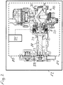
- FIG. 2 shows a commercial vehicle with a first aggregate system.
- the illustrated aggregate system 10 is part of a commercial vehicle 12, which is driven by a drive motor 14.
- the drive motor 14 is not shown as part of the unit system 10, and this is not attributed.
- the drive motor 14 can mechanically drive an aggregate 16 via a connecting element, for example a shaft 18.
- the illustrated unit 16 may, for example, designate a compressor capable of generating compressed air.
- the drive motor 14 can transmit torque to the shaft 18 via gears 52, whereby a crankshaft 54 of the unit 16 can be moved.
- the shaft 18 is optional and may also be omitted in an alternative embodiment, not shown. At least one of the gears 52 can then sit directly on the coupling and can be understood in this alternative embodiment as a connecting element.
- the connecting element may also be designed such that it comprises the shaft 18 and the gear 52.
- a clutch 20 may be provided, which may, for example, mechanically decouple the crankshaft 54 from the shaft 18.
- the clutch can be controlled directly or indirectly via a control unit 34.
- the clutch 20 may be pneumatically operable such that the controller 34 appropriately actuates pneumatic shift valves to open or close the clutch 20.
- the control of the clutch 20 by the control unit 34 is in FIG. 2 indicated only schematically.
- the control unit 34 may be, for example, a control unit 34 of a compressed air treatment plant downstream of the unit 16.
- the control unit 34 can control other functions in connection with the compressed air preparation, for example a regeneration function of an air dryer, not shown.
- the controller 34 may also control a motor control of the drive motor 14.
- the aggregate system 10 may include a first bearing 22 and a second bearing 24 for supporting the shaft 18. Furthermore, the aggregate system 10, a third camp 26, a fourth Bearings 28 and a fifth bearing 30 for supporting the crankshaft 54 and the crankshaft 54 possibly movably arranged parts include. A deviating arrangement or use of the bearings 22, 24, 26, 28, 30 within the unit system 10 is possible. For example, in the above-mentioned, not shown alternative embodiment, which is realized without the shaft 18, the bearing 22 may be integrated into the coupling 20 while the bearing 24 may be omitted.
- bearings 22, 24, 26, 28, 30 there may be two types of radially and / or axially loaded bearings 22, 24, 26, 28, 30. These are the clutch 20 upstream first bearing 22 and the second bearing 24, which always run when the drive motor 14 is in operation. The remaining bearings, that is, the third bearing 26, the fourth bearing 28 and the fifth bearing 30 are connected downstream of the clutch 20, so that they run along only when the unit 16 is switched on. In particular, during the connection process when closing the clutch 20 and when starting the unit 16, there are very high dynamic loads on the bearings 22, 24, 26, 28, 30 with contact and thus mixed friction between the fixed and the moving parts of the bearings 22, 24, 26, 28, 30.
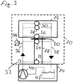
- FIG. 3 shows a schematic representation of an aggregate system.
- This in FIG. 3 illustrated unit system 10 shows in addition to the unit 16, the shaft 18 and the clutch 20 in particular an oil circuit 32, which supplies starting from the drive motor 14, an inlet 36 of an oil pump 40 with oil.
- the oil pump 40 and an oil sump 42, from which the oil pump 40 sucks oil are shown as an integral part of the drive motor 14, since the drive motor 14 usually can not be permanently functional without oil circuit 32.
- Starting from the inlet 36 oil can be led to the first bearing 22, the second bearing 24, the third bearing 26, the fourth bearing 28 and the fifth bearing 30.
- the coupling 20 may also be supplied from the inlet 36 with oil. Excess oil can flow back from the bearings 22, 24, 26, 28 and 30 via a return line 38 into the oil sump 42.
- the clutch 20 is supplied with oil, excess oil can also flow back from there via the return line 38 into the oil sump 42.
- the parallel supply shown in the figure is only to be understood as an example.
- the oil circuit 32 used for lubrication may alternatively also provide a serial supply or a mixed form of serial and parallel supply for lubrication.
- a pressure sensor 44 may be arranged at the inlet 36.
- the pressure sensor 44 can be dispensed with, for example, if a corresponding oil pressure signal can be read out by an oil pressure sensor which is not explicitly shown, already present on the drive motor 14, or if a corresponding oil pressure signal is already present on the CAN bus and can be read out.
- pressure sensors may be provided at different locations of the oil circuit 32 or the pressure sensor 44 shown may be moved within the oil circuit. Furthermore, one or more temperature sensors can be arranged at different locations of the oil circuit 32. It is also possible to provide a sensor or a plurality of sensors for determining the viscosity of the oil delivered by the oil pump at different points. Sensors for determining the temperature and the viscosity of the oil can in particular at the same portion of the inlet 36th be arranged, on which the pressure sensor 44 is already arranged. The inlet 36 of the oil circuit 32 may continue to be provided if necessary for cooling the unit 16 when corresponding oil passages are integrated into the oil circuit 32.
- the oil supply via the inlet 36 can be produced for example by a connection between a main oil passage of the unit 16 and an engine oil gallery of the drive motor 14.
- the unit 16 for example, a compressor, should be switched on only at a sufficient oil flow to ensure adequate lubrication of all bearings 22, 24, 26, 28, 30 and the above-described harmful signs of wear on the bearings 22, 24, 26, 28th 30 as low as possible. If the clutch 20 is also supplied from the inlet 36 with oil, should also be paid to a sufficient flow of oil to the clutch, in order to keep the mentioned signs of wear as low as possible at this point.
- clutch 20 of the oil pump 40 is at the individual bearings 22, 24, 26, 28, 30 and the clutch 20 a with provided the distance to the oil pump sloping oil pressure.
- This pressure drop can occur in particular in a serial supply through the oil circuit 32 amplified. This can be properly taken into account in the positioning of the pressure sensor 44, the determination of the time interval .DELTA.t and the determination of the minimum oil pressure.
- FIG. 4 shows a first symbolic representation for illustrating a control of an aggregate system
- FIG. 5 shows a second symbolic representation to illustrate a control of an aggregate system.
- input variables 50 which are supplied to the control unit 34.
- the controller 34 may generate a "clutch open” control signal 46 or a "clutch close” control signal 48 by which the clutch 20 opens or closes, such that the engine 16 is mechanically decoupled from the shaft 18 becomes.
- the inputs may include, for example, the oil pressure, the oil temperature, the "ignition on” signal, and / or a circuit pressure for clutch actuation if the clutch is pneumatically actuatable.
- oil pressure and oil temperature can be ensured, for example, via a connection to the CAN bus of the commercial vehicle. It is also conceivable to provide in the aggregate system own sensors for determining the input variables. Depending on the received or determined input variables, the actuation of the clutch 20 can be determined, for example, dynamically or statically during the commissioning of the drive motor. A dynamic determination of the deceleration may, for example, be based on the oil pressure and a static determination may, for example, be based on a predefinable time interval ⁇ t. Ideally, the processing of the input variables 50 and the generation and transmission of the control signals 46, 48 can be carried out by a control unit 34 already present in the utility vehicle, for example the control unit of an electronic compressed air preparation system.
- the oil pressure for example, 1 bar can be set. This minimum oil pressure must then be exceeded in the oil circuit to allow the clutch to close.
- the lower limit for the oil temperature for example, -30 ° C can be set. This limit for the oil temperature must be exceeded in addition to the minimum oil pressure, for example 1 bar, to allow the clutch to close.
- the consideration of the oil temperature in addition to the oil pressure is optional.
- the viscosity of the oil can be determined directly, which is directly correlated with the oil temperature. The consideration of the viscosity is optional.
- a predetermined time interval .DELTA.t can be waited after commissioning of the drive motor until the open clutch may be closed. This procedure can be selected, for example, if there is no access to the engine parameters oil pressure and oil temperature.
- the time interval .DELTA.t corresponds to a switch-on delay, which can be set as a fixed value relative to the starting operation of the drive motor or another relevant and characteristic process at the beginning of the pressure build-up in the oil circuit.
- the opening of the clutch can also be based on the signal "ignition on" before the start-up of the drive motor, when the clutch is closed in its rest position. This has already been described in connection with the use of a minimum oil pressure.
- the switch-on delay serves as protection to initially ensure an actual oil inflow to the bearing.
- the actual oil inflow can only be used up to 30 seconds after the start of the drive motor.
- the delay time selected for the time interval .DELTA.t can be selected to be shorter from an ideal period of time from the point of view of the oil supply. For example, instead of 30 seconds, it can only be 15 seconds. Even with this shortened period of wear can be greatly reduced.
- the input 50 may also include the signal "ignition on”. If the signal "ignition on” is present, the coupling can be opened immediately, if possible. For example, for this purpose, a sufficient supply pressure in a compressed air reservoir may be necessary if the clutch pneumatically actuated is. A minimum switching pressure may be 6.5 bar, for example. To open the clutch can be provided that the provided supply pressure must exceed the minimum switching pressure.
Landscapes
- Engineering & Computer Science (AREA)
- Mechanical Engineering (AREA)
- Chemical & Material Sciences (AREA)
- Combustion & Propulsion (AREA)
- Transportation (AREA)
- General Engineering & Computer Science (AREA)
- Fluid Mechanics (AREA)
- Physics & Mathematics (AREA)
- Automation & Control Theory (AREA)
- Hydraulic Clutches, Magnetic Clutches, Fluid Clutches, And Fluid Joints (AREA)
- Auxiliary Drives, Propulsion Controls, And Safety Devices (AREA)
- General Details Of Gearings (AREA)
- Control Of Transmission Device (AREA)
Description
- Die vorliegende Erfindung betrifft ein Verfahren zum Betreiben eines Aggregatsystems eines Nutzfahrzeugs umfassend ein von einem Antriebsmotor des Nutzfahrzeugs mechanisch angetriebenes Aggregat, ein Verbindungselement zur Übertragung mechanischer Antriebskraft von dem Antriebsmotor auf das Aggregat und eine Kupplung zur Unterbrechung der über das Verbindungselement auf das Aggregat übertragenen Antriebskraft, wobei das Aggregatsystem weiterhin zumindest ein Lager umfasst, das über einen Ölkreislauf des Antriebsmotors mit Öl geschmiert wird.
Die vorliegende Erfindung betrifft weiterhin ein Aggregatsystem eines Nutzfahrzeugs umfassend ein von einem Antriebsmotor des Nutzfahrzeugs mechanisch angetriebenes Aggregat, ein Verbindungselement zur Übertragung mechanischer Antriebskraft von dem Antriebsmotor auf das Aggregat und eine Kupplung zur Unterbrechung der über das Verbindungselement auf das Aggregat übertragenen Antriebskraft, wobei das Aggregatsystem weiterhin zumindest ein Lager umfasst, das über einen Ölkreislauf des Antriebsmotors mit Öl geschmiert ist. - Gattungemässe Verfahren zum Betreiben eines Aggregatsystems eines Nutzfahrzeugs und ein entsprechendes Aggregatsystem sind aus der
EP 0 184 685 A2 bekannt. Nutzfahrzeuge verfügen in der Regel über eine ganze Reihe von Aggregaten, die direkt oder indirekt mit Hilfe eines Antriebsmotors des Nutzfahrzeugs angetrieben werden, wobei der Antriebsmotor des Nutzfahrzeugs zugleich Energie bereitstellt, die zum Vortrieb des Nutzfahrzeugs genutzt wird. Um eine möglichst einfache Energieübertragung von dem Antriebsmotor auf das Aggregat zu gewährleisten, wird das Aggregat in der Regel in der direkten Nachbarschaft des Antriebsmotors angeordnet. Die Schmierung von Lagerungen, beispielsweise einem zur EnergieÜbertragung von dem Antriebsmotor auf das Aggregat genutzten Verbindungselement, das beispielsweise als Welle und/oder Zahnrad ausgeführt sein kann, kann der Einfachheit halber mithilfe eines Ölkreislaufs des Antriebsmotors realisiert sein, der bereits die in dem Antriebsmotor selbst vorhandenen Lagerungen in bekannter Weise schmiert. Zu diesem Zweck kann eine Erweiterung des Ölkreislaufs des Antriebsmotors auf das Aggregat und/oder das das Aggregat antreibende Verbindungselement vorgesehen sein. - Problematisch an dieser Vorgehensweise sind die Verlängerungen der Zuläufe und Abläufe des Ölkreislaufs auf die Lagerungen des Verbindungselementes und/oder des Aggregates, da der Aufbau der Ölzirkulation innerhalb des erweiterten Ölkreislaufs aufgrund der verlängerten Fließwege in den Zu- und Abläufen eine längere Zeitspanne in Anspruch nimmt. Dies kann dazu führen, dass bei einer Inbetriebnahme des Antriebsmotors Lagerungen des Verbindungselementes und/oder des Aggregates bewegt werden, ohne dass diese ausreichend geschmiert sind. Ein solches "trockenes" Bewegen von Lagern kann zu einem erhöhten Verschleiß des angetriebenen Aggregates führen, der sich in einer verstärkten Abnutzung der zeitweise nicht ausreichend geschmiert bewegten Lager des Aggregatsystems bemerkbar machen kann.
- Der Erfindung liegt die Aufgabe zugrunde, diesen Verschleiß zu reduzieren.
- Diese Aufgabe wird durch die Merkmale der unabhängigen Ansprüche gelöst.
- Vorteilhafte Ausgestaltungen und Weiterbildungen der Erfindung ergeben sich aus den abhängigen Ansprüchen.
- Das gattungsgemäße Verfahren wird durch die vorliegende Erfindung dadurch weiterentwickelt, dass die Kupplung durch ein Steuersignal geschlossen wird, wenn eine Zeitspanne Δt nach einer Inbetriebnahme des Antriebsmotors verstrichen ist und/oder ein Mindestöldruck in dem Ölkreislauf vorliegt. Auf diese Weise kann eine Bewegung oder Belastung des Lagers erst erfolgen, wenn eine ausreichende Schmierung des Lagers sichergestellt ist. Dies kann durch ein gesteuertes zeitlich verzögertes Schließen der Kupplung realisiert werden, wobei die Kupplung erst nach dem Verstreichen einer Zeitspanne Δt nach der Inbetriebnahme des Antriebsmotors geschlossen wird. Alternativ oder zusätzlich hierzu kann der Schutz des Lagers vor Verschleiß auch durch das Messen eines Öldrucks in dem Ölkreislauf realisiert werden, der einen Mindestöldruck überschreiten muss, bevor die Kupplung durch ein Steuersignal geschlossen wird. Beide Möglichkeiten stellen eine ausreichende Versorgung des so geschützten Lagers des Aggregatsystems mit Öl sicher, bevor eine Bewegung oder Belastung des Lagers erfolgt. Dies reduziert den an dem Lager auftretenden Verschleiß. Das in dem Aggregatsystem vorhandene Lager kann beispielsweise eine Lagerung sein, an der zwei Teile gegeneinander drehend bewegt werden. Das Lager kann beispielsweise an dem Aggregat oder dem zum Antrieb des Aggregates verwendeten Verbindungselement, beispielsweise einer Welle und/oder einem Zahnrad, oder der Kupplung angeordnet sein. Spezielle Beispiele für das Lager sind im Zusammenhang mit der speziellen Ausführungsform des Aggregatsystems explizit angegeben. Das Lager kann entweder ständig mit dem Antriebsmotor gekoppelt sein oder durch die Kupplung von dem Antriebsmotor entkoppelbar sein. In beiden Fällen ist die Belastung des Lagers durch das Anlaufen des angetriebenen Aggregates besonders groß, so dass beim Anlaufen des Aggregates eine ausreichende Schmierung besonders wichtig ist. Als Schmierung mit Öl wird insbesondere die Ausbildung eines Ölfilms bezeichnet, welche die zwei in dem Lager gegeneinander bewegten Teile voneinander trennt, um den Verschleiß in dem Lager zu reduzieren. Unter der Inbetriebnahme des Antriebsmotors wird das Starten des Antriebsmotors mit dem Druckaufbau in dem Ölkreislauf des Antriebsmotors aus einem inaktiven deaktivierten Zustand verstanden. Ein nicht in Betrieb genommener Antriebsmotor befindet sich dementsprechend in Ruhe, so dass die einzelnen Bestandteile des Antriebsmotors ihre relative Position zueinander nicht ändern. Als Zeitpunkt für die Inbetriebnahme des Antriebsmotors kann die Erzeugung eines Signals "Zündung ein" durch eine Zündung des Nutzfahrzeugs, das Erreichen einer Leerlaufdrehzahl durch den Antriebsmotor oder ein anderes geeignetes und charakteristisches Kriterium sein.
- Vorteilhafterweise kann vorgesehen sein, dass die aufgrund des Steuersignals geschlossene Kupplung geöffnet und offen gehalten wird, solange der Mindestöldruck in dem Ölkreislauf unterschritten wird. Dies dient ebenfalls der Vermeidung von unnötigem Lagerverschleiß und kann beispielsweise auch die Überhitzung einer nass laufenden Kupplung durch trockene oder unzureichend geschmierte Kuppelvorgänge verhindern. Es kann also durch das automatische Öffnen und Offenhalten der Kupplung eine Bewegung oder Belastung des Lagers bei nicht ausreichender Schmierung verhindert werden, so dass der an dem Lager auftretende Verschleiß reduziert wird. Der Öldruck kann auch während des Betriebs des Aggregatsystems plötzlich unter einen Mindestwert absinken, beispielsweise, wenn der Ölverbrauch durch andere in dem Nutzfahrzeug vorgesehene Komponenten geändert wird.
- In diesem Zusammenhang kann vorgesehen sein, dass der Mindestöldruck bei einer Mindestöltemperatur oder -viskosität vorliegen muss. Die Berücksichtigung der Öltemperatur im Zusammenhang mit dem Öldruck kann zur Absicherung dienen, um zu vermeiden, dass ein ausreichender Öldruck vorliegt, der aber aufgrund von einer zu niedriger Öltemperatur und dadurch bedingten hohen Viskosität des Öls nicht zu einem tatsächlichen Ölzufluss zu dem zu schmierenden Lager führt. Dieses Phänomen kann besonders bei mit Ruß oder anderen Partikeln belasteten Ölen auftreten, wie sie nach einer gewissen Nutzungsdauer in Nutzfahrzeugen üblich sind.
- Nützlicherweise kann vorgesehen sein, dass die Kupplung vor der Inbetriebnahme des Antriebsmotors geöffnet wird. Aus Sicherheitsgründen kann vorgesehen sein, dass die Kupplung eine geschlossene Ruhestellung aufweist. Das kann bei einem abgestellten Nutzfahrzeug zur Folge haben, dass das Lager des Aggregatsystems unter erhöhtem Verschleiß bei einer nicht ausreichenden Schmierung während der Inbetriebnahme des Antriebsmotors mitbewegt wird. Das Überführen der Kupplung in den geöffneten Zustand vor der Inbetriebnahme des Antriebsmotors kann daher eine Voraussetzung für eine Reduzierung des an dem Lager auftretenden Verschleißes sein.
- Weiterhin kann vorgesehen sein, dass vor dem Öffnen der Kupplung überprüft wird, ob das Öffnen der Kupplung möglich ist. Die Überprüfung, ob das Öffnen der Kupplung überhaupt möglich ist, verhindert die Überführung der Kupplung in einen Zwischenzustand zwischen den klar definierten offenen und geschlossenen Betriebszuständen. Beispielsweise kann bei einer pneumatisch betätigten Kupplung ein zum Öffnen der Kupplung nicht ausreichender Versorgungsdruck vorhanden sein, der nicht ausreichend ist, die Kupplung aus dem geschlossenen Betriebszustand in den geöffneten Betriebszustand zu überführen. Wird das Öffnen der Kupplung dennoch eingeleitet, wird die Kupplung nicht vollständig geöffnet, so dass ein undefinierter Zwischenzustand entsteht, bei dem eine erhöhte Reibung innerhalb der Kupplung auftreten kann. Dieser Zwischenzustand kann, aufgrund der auftretenden hohen Reibung, die Kupplung innerhalb kürzester Zeit beschädigen oder zerstören und zu ihrem Ausfall führen. Die Überprüfung, ob das Öffnen der Kupplung möglich ist, schützt somit das Aggregatsystem vor Verschleiß und Beschädigungen. Eine Überprüfung, die ergeben hat, dass die Kupplung geöffnet werden kann, kann das Öffnen der Kupplung umfassen oder das Öffnen der Kupplung verursachen.
- Das gattungsgemäße Aggregatsystem wird durch die vorliegende Erfindung dadurch weiterentwickelt, dass ein Steuergerät vorgesehen ist, das dazu eingerichtet ist, die Kupplung durch ein Steuersignal zu schließen, wenn eine Zeitspanne Δt nach einer Inbetriebnahme des Antriebsmotors verstrichen ist und/oder ein Mindestöldruck in dem Ölkreislauf vorliegt.
- Die Vorteile und Besonderheiten des in den abhängigen Ansprüchen beschriebenen Verfahrens können in gleicher Weise auch im Rahmen eines Aggregatsystems umgesetzt werden.
- Vorteilhafte Ausführungsformen und Besonderheiten des Aggregatsystems ergeben sich daher in gleicher Weise aus den abhängigen Vorrichtungsansprüchen und sind im Zusammenhang mit diesen angegeben.
- Es kann beispielsweise vorgesehen sein, dass das Steuergerät dazu eingerichtet ist, die aufgrund des Steuersignals geschlossene Kupplung zu öffnen und offen zu halten, solange der Mindestöldruck in dem Ölkreislauf unterschritten ist.
- Weiterhin kann auch vorgesehen sein, dass der Mindestöldruck bei einer Mindestöltemperatur oder -Viskosität vorliegen muss.
- Von Vorteil kann auch sein, dass das Steuergerät dazu eingerichtet ist, die Kupplung vor der Inbetriebnahme des Antriebsmotors zu öffnen.
- Ebenfalls kann es vorteilhaft sein, dass das Steuergerät dazu eingerichtet ist, vor dem Öffnen der Kupplung zu überprüfen, ob das Öffnen der Kupplung möglich ist.
- Die Erfindung wird nun mit Bezug auf die begleitenden Zeichnungen anhand bevorzugter Ausführungsformen beispielhaft erläutert.
- Es zeigen:
- Figur 1
- ein Flussdiagramm für den Betrieb eines Aggregatsystems;
- Figur 2
- ein Nutzfahrzeug mit einem ersten Aggregatsystem;
- Figur 3
- eine schematische Darstellung eines Aggregatsystems;
- Figur 4
- eine erste symbolhafte Darstellung zur Veranschaulichung eines Aggregatsystems; und
- Figur 5
- eine zweite symbolhafte Darstellung zur Veranschaulichung einer Steuerung eines Aggregatsystems.
- In den folgenden Zeichnungen bezeichnen gleiche Bezugszeichen gleiche oder gleichartige Teile.
-
Figur 1 zeigt ein Flussdiagramm für den Betrieb eines Aggregatsystems. Ausgangspunkt ist Schritt 100 "Antriebsmotor aus". Der Antriebsmotor kann zum mechanischen Antrieb eines Aggregates des Aggregatsystems und gleichzeitig zum Antrieb des Nutzfahrzeugs dienen. Der Betriebszustand "Antriebsmotor aus" kann beispielsweise bei einem abgestellten Nutzfahrzeug vorkommen, dessen Antriebsmotor vollständig deaktiviert ist. Wenn der Antriebsmotor aus ist, das heißt deaktiviert ist, kann auch die Kupplung des Aggregatsystems geschlossen sein. Die Kupplung des Aggregatsystems kann aus Sicherheitsgründen eine geschlossene Ruhestellung aufweisen, um beispielsweise eine Inbetriebnahme des abgestellten Nutzfahrzeugs bei defekter Kupplungssteuerung zu ermöglichen. Im anschließenden Schritt 102 kann überprüft werden, ob das Signal "Zündung ein" vorliegt, falls nein, Schritt 102-Nein, ändert sich an dem allgemeinen Betriebszustand nichts, da zu Schritt 100 zurückgekehrt wird. Der Antriebsmotor bleibt deaktiviert und dementsprechend ist auch das Aggregatsystem an sich nicht aktiv. Falls das Signal "Zündung ein" vorliegt, Schritt 102-Ja, kann in Schritt 104 überprüft werden, ob das Öffnen der Kupplung möglich ist. Das Signal "Zündung ein" kann jedes Signal sein, das eine Inbetriebnahme des Antriebsmotors einleitet, beispielweise ein elektrischer Impuls, der durch das Betätigen einer Zündung des Nutzfahrzeugs erzeugt werden kann. Die Kupplung als Teil des Aggregatsystems kann beispielsweise pneumatisch betätigbar sein. Das Öffnen der Kupplung kann in diesem Fall nur zuverlässig erfolgen, wenn ein ausreichender Versorgungsdruck vorhanden ist. Wenn ein ausreichender Versorgungsdruck zum Öffnen der Kupplung vorhanden ist, so ist das Öffnen der Kupplung möglich, Schritt 104-Ja, und es kann bei Schritt 106 mit dem Öffnen der Kupplung fortgefahren werden. In Schritt 106, Kupplung öffnen, kann ein Signal zum Öffnen der Kupplung beziehungsweise das Öffnen der Kupplung erfolgen. Als Folge kann mit Schritt 108 fortgefahren werden, der den offenen Zustand der Kupplung des Aggregatsystems bezeichnet. Wenn festgestellt wird, dass das Öffnen der Kupplung in Schritt 104 nicht möglich ist, Schritt 104-Nein, kann bei Schritt 116 fortgefahren werden, da die Kupplung geschlossen bleibt und nicht geöffnet werden soll. Beispielsweise kann das Öffnen der Kupplung bei einem nicht ausreichenden Versorgungsdruck nicht möglich sein, wenn die Kupplung pneumatisch betätigbar ist. Durch den nicht ausreichenden Versorgungsdruck kann die zum vollständigen Öffnen der Kupplung notwendige Kraft nicht erzeugt werden, so dass dann die Kupplung zwar aus dem geschlossenen Schaltzustand entfernt, jedoch nicht vollständig in den offenen Schaltzustand überführt wird. Dieser undefinierte Zwischenzustand kann bei einer Bewegung der Kupplung durch einen hohen reibungs- und hitzebedingten Verschleiß an der Kupplung gekennzeichnet sein, der die Kupplung in kurzer Zeit beschädigen kann. Schritt 116 bezeichnet dementsprechend den geschlossenen Zustand der Kupplung. - Ausgehend von Schritt 108, dem geöffneten Zustand der Kupplung und Schritt 116, dem geschlossenen Zustand der Kupplung, kann jeweils mit Schritt 110 fortgefahren werden. In Schritt 110 wird überprüft, ob das Signal "Zündung aus" vorliegt. Durch das Signal "Zündung aus" kann beispielsweise der Antriebsmotor, der das Aggregatsystem antreibt, deaktiviert werden. Das Signal "Zündung aus" kann ein eigenständiges, von dem Signal "Zündung ein" verschiedenes Signal darstellen oder auch durch das Fehlen des Signals "Zündung ein" definiert sein. Wenn das Signal "Zündung aus" vorliegt, Schritt 110-Ja, kann mit Schritt 100, Antriebsmotor aus, das heißt dem ursprünglichen Ausgangspunkt, fortgefahren werden. Die Kupplung kann dann ebenfalls ihre Ruhestellung wieder einnehmen, die insbesondere geschlossen sein kann, wenn sie sich nicht bereits in der Ruhestellung befindet. Liegt das Signal "Zündung aus" nicht vor, Schritt 110-Nein, so kann in Schritt 112 überprüft werden, ob eine Vorbedingung erfüllt ist. Die Vorbedingung kann beispielweise das Verstreichen einer Zeitspanne Δt seit der Inbetriebnahme des Antriebsmotors durch das Signal "Zündung ein" sein. Alternativ oder zusätzlich kann die Vorbedingung auch das Vorliegen eines Mindestöldrucks in einem Ölkreislauf des Antriebmotors sein. Der Mindestöldruck kann beispielsweise mithilfe eines Drucksensors an dem Ölkreislauf bestimmt werden. Zusätzlich zu einem Mindestöldruck kann auch eine Mindestöltemperatur oder eine Mindestölviskosität als Vorbedingung vorgesehen sein. Die Temperatur und die Viskosität des Öls können ebenfalls in einfacher Weise durch geeignete Sensoren in dem Ölkreislauf des Antriebsmotors bestimmt werden. Es ist möglich, dass die Temperatur und/oder die Viskosität des Öls bereits als Signale auf dem CAN-Bus vorliegen, die von einem Steuergerät eines Aggregatsystems mit einem Anschluss an den CAN-Bus eingelesen werden können.
- Ist die Vorbedingung erfüllt, Schritt 112-Ja, so kann in Schritt 114 die Kupplung geschlossen werden. Hiervon ausgehend kann bei Schritt 116 fortgefahren werden, der den geschlossenen Zustand der Kupplung bezeichnet.
- Der zeitliche Ablauf der einzelnen Schritte, insbesondere die Detektion des Signals "Zündung ein" in Schritt 102 und das Öffnen der Kupplung in Schritt 106, können zeitlich so auf die Inbetriebnahme des Antriebsmotors abgestimmt sein, dass die Kupplung geöffnet wird, bevor der Antriebsmotor in Betrieb genommen wird. Auf diese Weise wird eine Bewegung oder Belastung des Lagers in dem Aggregatsystem vor einer Sicherstellung einer ausreichenden Schmierung des Lagers verhindert. Die Überprüfung, ob das Öffnen der Kupplung überhaupt möglich ist, in Schritt 104, sorgt in diesem Zusammenhang dafür, dass die Kupplung keine undefinierten Betriebszustände einnehmen kann. Insbesondere wird verhindert, dass die Kupplung eine Zwischenstellung zwischen der geschlossenen und der offenen Position einnehmen kann. Auf diese Weise kann das Auftreten einer stark erhöhten Reibung verhindert werden, die zu einer hohen Wärmeentwicklung in der Kupplung führen kann. Grundsätzlich kann die Kupplung geöffnet werden, wenn die Vorbedingung nicht erfüllt ist, Schritt 112-Nein. Auf diese Weise kann bei einer nicht ausreichenden Schmierung des Lagers, das Aggregatsystem vor einem verschleißbedingten Ausfall geschützt werden. Es ist denkbar während des Schritts 112-Ja, das Öffnen der Kupplung analog zu Schritt 104 durchzuführen.
-
Figur 2 zeigt ein Nutzfahrzeug mit einem ersten Aggregatsystem. Das dargestellte Aggregatsystem 10 ist Bestandteil eines Nutzfahrzeugs 12, welches durch einen Antriebsmotor 14 angetrieben wird. Der Antriebsmotor 14 ist nicht als Bestandteil des Aggregatsystems 10 dargestellt, und diesem nicht zugerechnet. Der Antriebsmotor 14 kann ein Aggregat 16 über ein Verbindungselement, beispielsweise eine Welle 18, mechanisch antreiben. Das dargestellte Aggregat 16 kann beispielsweise einen Kompressor bezeichnen, der Druckluft erzeugen kann. Der Antriebsmotor 14 kann über Zahnräder 52 Drehmoment auf die Welle 18 übertragen, wodurch eine Kurbelwelle 54 des Aggregates 16 bewegt werden kann. Die Welle 18 ist optional und kann in einer nicht dargestellten alternativen Ausführungsform auch entfallen. Zumindest eines der Zahnräder 52 kann dann direkt an der Kupplung sitzen und kann bei dieser alternativen Ausführungsform als Verbindungselement aufgefasst werden. Das Verbindungselement kann ebenfalls derart ausgestaltet sein, dass es die Welle 18 und das Zahnrad 52 umfasst. - Zur Unterbrechung der mechanischen Kraftübertragung zwischen dem Antriebsmotor 14 und dem Aggregat 16 kann eine Kupplung 20 vorgesehen sein, die beispielsweise die Kurbelwelle 54 von der Welle 18 mechanisch entkoppeln kann. Die Kupplung kann direkt oder indirekt über ein Steuergerät 34 ansteuerbar sein. Die Kupplung 20 kann beispielsweise pneumatisch betätigbar sein, so dass das Steuergerät 34 pneumatische Schaltventile in geeigneter Weise betätigt, um die Kupplung 20 zu öffnen oder zu schließen. Die Ansteuerung der Kupplung 20 durch das Steuergerät 34 ist in
Figur 2 lediglich schematisch angedeutet. Das Steuergerät 34 kann beispielsweise ein Steuergerät 34 einer dem Aggregat 16 nachgeordneten Druckluftaufbereitungsanlage sein. Das Steuergerät 34 kann im Zusammenhang mit der Druckluftaufbereitung weitere Funktionen steuern, beispielsweise eine Regenerationsfunktion eines nicht dargestellten Lufttrockners. Das Steuergerät 34 kann auch eine Motorsteuerung des Antriebsmotors 14 steuern. Das Aggregatsystem 10 kann ein erstes Lager 22 und ein zweites Lager 24 zur Lagerung der Welle 18 umfassen. Weiterhin kann das Aggregatsystem 10 ein drittes Lager 26, ein viertes Lager 28 und ein fünftes Lager 30 zur Lagerung der Kurbelwelle 54 und der an der Kurbelwelle 54 eventuell beweglich angeordneten Teile umfassen. Eine hiervon abweichende Anordnung oder Verwendung der Lager 22, 24, 26, 28, 30 innerhalb des Aggregatsystems 10 ist möglich. Beispielsweise kann bei der oben bereits erwähnten, nicht dargestellten alternativen Ausführungsform, die ohne die Welle 18 realisiert ist, das Lager 22 in die Kupplung 20 integriert sein während das Lager 24 entfallen kann. - Bei dem Aggregatsystem 10 kann es zwei Arten von radial und/oder axial beanspruchten Lagern 22, 24, 26, 28, 30 geben. Das sind das der Kupplung 20 vorgeschaltete erste Lager 22 und das zweite Lager 24, die immer mitlaufen, wenn der Antriebsmotor 14 in Betrieb ist. Die übrigen Lager, das heißt das dritte Lager 26, das vierte Lager 28 und das fünfte Lager 30 sind der Kupplung 20 nachgeschaltet, so dass sie nur dann mitlaufen, wenn das Aggregat 16 zugeschaltet ist. Insbesondere während des Zuschaltvorgangs beim Schließen der Kupplung 20 und beim Anlaufen des Aggregates 16 kommt es zu sehr hohen dynamischen Lasten an den Lagern 22, 24, 26, 28, 30 mit Kontakt und damit Mischreibung zwischen den feststehenden und den beweglichen Teilen der Lager 22, 24, 26, 28, 30. Das Durchfahren des Mischreibungsgebietes und der direkte Kontakt, besonders wenn bereits ein erhöhter Schmutzanteil in dem vorhandenen Öl vorliegt, ist nachteilig da es zu erhöhtem Verschleiß der Lager 22, 24, 26, 28, 30 kommen kann oder eben entsprechende Robustheit verbessernde Maßnahmen erfordert, die sehr kostenintensiv sein können. Schmutzanteile mit bis zu 3 Prozent Volumenanteil des Öls sind nicht unüblich, wobei als Schmutz hauptsächlich Ruß vorkommt. Eine ausreichende Schmierung kann jedoch den Verschleiß auch bei stark verschmutztem Öl deutlich reduzieren.
- Weiterhin werden bei der beschriebenen Ausführungsform insbesondere das zweite Lager 24 und das dritte Lager 26, die beide direkt an die Kupplung 20 angrenzen, im Moment der Betätigung der Kupplung 20 schlagartig in axialer Richtung beansprucht. Auch hier kann die bereits erwähnte Mischreibung durch eine ausreichende Schmierung vermieden werden.
-
Figur 3 zeigt eine schematische Darstellung eines Aggregatsystems. Das inFigur 3 dargestellte Aggregatsystem 10 zeigt neben dem Aggregat 16, der Welle 18 und der Kupplung 20 insbesondere einen Ölkreislauf 32, der ausgehend von dem Antriebsmotor 14 einen Zulauf 36 von einer Ölpumpe 40 mit Öl versorgt. Die Ölpumpe 40 sowie ein Ölsumpf 42, aus dem die Ölpumpe 40 Öl ansaugt, sind als integraler Bestandteil des Antriebsmotors 14 dargestellt, da der Antriebsmotor 14 üblicherweise nicht ohne Ölkreislauf 32 dauerhaft funktionsfähig sein kann. Ausgehend von dem Zulauf 36 kann Öl zu dem ersten Lager 22, dem zweiten Lager 24, dem dritten Lager 26, dem vierten Lager 28 und dem fünften Lager 30 geführt werden. Die Kupplung 20 kann ebenfalls ausgehend vom Zulauf 36 mit Öl versorgt sein. Überschüssiges Öl kann ausgehend von den Lagern 22, 24, 26, 28 und 30 über einen Rücklauf 38 in den Ölsumpf 42 rückströmen. Wenn auch die Kupplung 20 mit Öl versorgt wird, kann überschüssiges Öl auch von dort über den Rücklauf 38 in den Ölsumpf 42 zurückströmen. Die in der Figur dargestellte parallele Versorgung ist nur beispielhaft zu verstehen. Der zur Schmierung verwendete Ölkreislauf 32 kann alternativ auch eine serielle Versorgung oder eine Mischform aus serieller und paralleler Versorgung zur Schmierung vorsehen. An dem Zulauf 36 kann beispielsweise ein Drucksensor 44 angeordnet sein. Auf den Drucksensor 44 kann beispielsweise verzichtet werden, wenn ein entsprechendes Öldrucksignal von einem nicht explizit dargestellten, am Antriebsmotor 14 bereits vorhandenen Öldrucksensor ausgelesen werden kann oder wenn ein entsprechendes Öldrucksignal auf dem CAN-Bus bereits vorhanden ist und ausgelesen werden kann. Je nach Bedarf können weitere inFigur 3 nicht explizit dargestellte Drucksensoren an unterschiedlichen Stellen des Ölkreislaufs 32 vorgesehen sein oder der dargestellte Drucksensor 44 innerhalb des Ölkreislaufs verschoben werden. Weiterhin können ein oder mehrere Temperatursensoren an unterschiedlichen Stellen des Ölkreislaufs 32 angeordnet werden. Ebenso ist es möglich, an unterschiedlichen Stellen einen Sensor oder mehrere Sensoren zur Bestimmung der Viskosität des von der Ölpumpe geförderten Öls vorzusehen. Sensoren zur Bestimmung der Temperatur und der Viskosität des Öls können insbesondere an demselben Abschnitt des Zulaufs 36 angeordnet sein, an dem bereits der Drucksensor 44 angeordnet ist. Der Zulauf 36 des Ölkreislaufs 32 kann weiterhin bei Bedarf zur Kühlung des Aggregates 16 vorgesehen sein, wenn entsprechende Ölführungen in den Ölkreislauf 32 integriert werden. - Die Ölversorgung über den Zulauf 36 kann beispielsweise durch eine Verbindung zwischen einem Hauptölkanal des Aggregates 16 und einer Motorölgalerie des Antriebsmotors 14 hergestellt werden. Es besteht also eine Abhängigkeit zwischen dem Öldruckaufbau in den Lagern 22, 24, 26, 28, 30 und der Versorgung anderer Lagerstellen am Antriebsmotor 14. Dadurch kann ein ausreichender Ölfluss erst einige Zeit nach Start des Antriebsmotors 14 zur Verfügung stehen, insbesondere bei Kälte. Das Aggregat 16, beispielsweise ein Kompressor, sollte erst bei einem ausreichenden Ölfluss zugeschaltet werden, um eine ausreichende Schmierung aller Lager 22, 24, 26, 28, 30 zu gewährleisten und die oben beschriebenen schädlichen Verschleißerscheinungen an den Lagern 22, 24, 26, 28, 30 möglichst gering zu halten. Wenn die Kupplung 20 ebenfalls ausgehend vom Zulauf 36 mit Öl versorgt wird, sollte zusätzlich auch auf einen ausreichenden Ölfluss an der Kupplung geachtet werden, um auch an dieser Stelle die erwähnten Verschleißerscheinungen möglichst gering zu halten.
- Aufgrund der unterschiedlichen Abstände der Lager 22, 24, 26, 28, 30 und der eventuell ebenfalls an den Ölkreislauf 32 angeschlossen Kupplung 20 von der Ölpumpe 40 wird an den einzelnen Lagern 22, 24, 26, 28, 30 und der Kupplung 20 ein mit dem Abstand zur Ölpumpe abfallender Öldruck bereitgestellt. Dieser Druckabfall kann insbesondere bei einer seriellen Versorgung durch den Ölkreislauf 32 verstärkt auftreten. Dies kann in geeigneter Weise bei der Positionierung des Drucksensors 44, der Festlegung des Zeitintervalls Δt und der Festlegung des Mindestöldrucks berücksichtigt werden.
-
Figur 4 zeigt eine erste symbolhafte Darstellung zur Veranschaulichung einer Steuerung eines Aggregatsystems undFigur 5 zeigt eine zweite symbolhafte Darstellung zur Veranschaulichung einer Steuerung eines Aggregatsystems. Dargestellt in denFiguren 4 und5 sind Eingangsgrößen 50, die dem Steuergerät 34 zugeführt werden. In Abhängigkeit von den Werten der zugeführten Eingangsgrößen 50 kann das Steuergerät 34 ein Steuersignal "Kupplung öffnen" 46 oder ein Steuersignal "Kupplung schließen" 48 erzeugen, durch das die Kupplung 20 öffnet oder schließt, so dass das Aggregat 16 von der Welle 18 mechanisch entkoppelt wird. Die Eingangsgrößen können beispielsweise den Öldruck, die Öltemperatur, das Signal "Zündung ein" und/oder einen Kreisdruck zur Kupplungsbetätigung, falls die Kupplung druckluftbetätigbar ist, umfassen. Der Zugang zu den Motorparametern Öldruck und Öltemperatur kann beispielsweise über einen Anschluss an den CAN-Bus des Nutzfahrzeugs gewährleistet werden. Denkbar ist auch, in dem Aggregatsystem eigene Sensoren zur Bestimmung der Eingangsgrößen vorzusehen. In Abhängigkeit von den erhaltenen oder ermittelten Eingangsgrößen kann das Betätigen der Kupplung 20 beispielsweise dynamisch oder statisch bei der Inbetriebnahme des Antriebsmotors bestimmt werden. Eine dynamische Bestimmung der Verzögerung kann beispielsweise basierend auf dem Öldruck erfolgen und eine statische Bestimmung kann beispielsweise basierend auf einem vorgebbaren Zeitintervall Δt erfolgen. Idealerweise kann die Verarbeitung der Eingangsgrößen 50 und das Erzeugen und Aussenden der Steuersignale 46, 48 von einem bereits in dem Nutzfahrzeug vorhandenen Steuergerät 34 durchgeführt werden, beispielsweise dem Steuergerät eines elektronischen Druckluftaufbereitungssystems. In dem Druckluftaufbereitungssystem werden bereits üblicherweise einige softwaregestützte Funktionen dargestellt, die Kenntnisse des Druckluftsystems erfordern. Prinzipiell können aber auch andere Steuergeräte, soweit sie die benötigten Eingangsgrößen berücksichtigen und ein entsprechendes Steuersignal erzeugen können, benutzt werden. - Als unterer Grenzwert für den Öldruck kann beispielsweise 1 bar festgelegt werden. Dieser Mindestöldruck muss dann in dem Ölkreislauf überschritten werden, um das Schließen der Kupplung zu erlauben. Als unterer Grenzwert für die Öltemperatur kann beispielsweise -30 °C festgelegt werden. Dieser Grenzwert für die Öltemperatur muss zusätzlich zu dem Mindestöldruck von beispielsweise 1 bar überschritten werden, um ein Schließen der Kupplung zu erlauben. Die Berücksichtigung der Öltemperatur zusätzlich zu dem Öldruck ist optional. Alternativ zu der Öltemperatur kann auch direkt die Viskosität des Öls ermittelt werden, die direkt mit der Öltemperatur korreliert ist. Auch die Berücksichtigung der Viskosität ist optional.
- Anstatt des Öldrucks und eventueller weiterer Größen aus dem Ölkreislauf kann auch das Verstreichen eines vorgebbaren Zeitintervalls Δt nach der Inbetriebnahme des Antriebsmotors abgewartet werden, bis die geöffnete Kupplung geschlossen werden darf. Diese Vorgehensweise kann beispielsweise gewählt werden, wenn kein Zugang zu den Motorparametern Öldruck und Öltemperatur besteht. Das Zeitintervall Δt entspricht einer Einschaltverzögerung, die als fester Wert bezogen auf den Startvorgang des Antriebsmotors oder einen anderen relevanten und charakteristischen Vorgang am Beginn des Druckaufbaus im Ölkreislauf gesetzt werden kann. Das Öffnen der Kupplung kann auch basierend auf dem Signal "Zündung ein" vor der Inbetriebnahme des Antriebsmotors erfolgen, wenn die Kupplung in ihrer Ruhestellung geschlossen ist. Dies wurde bereits im Zusammenhang mit der Verwendung eines Mindestöldrucks beschrieben. Die Einschaltverzögerung dient zur Absicherung, um zunächst einen tatsächlichen Ölzufluss zu dem Lager zu gewährleisten. Der tatsächliche Ölzufluss kann erfahrungsgemäß erst bis zu 30 Sekunden nach dem Start des Antriebsmotors einsetzen. Bedingt durch die Komfortansprüche des Fahrzeugführers kann die für das Zeitintervall Δt gewählte Verzögerungszeit von einer aus Sicht der Ölversorgung idealen Zeitspanne kürzer gewählt werden. Beispielsweise kann sie anstelle von 30 Sekunden nur 15 Sekunden betragen. Auch bei dieser verkürzten Zeitspanne kann der Verschleiß noch stark reduziert werden.
- Die Eingangsgröße 50 kann auch das Signal "Zündung ein" umfassen. Wenn das Signal "Zündung ein" vorliegt, kann zunächst sofort die Kupplung geöffnet werden, wenn dies möglich ist. Beispielsweise kann hierfür ein ausreichender Versorgungsdruck in einem Druckluftvorratsbehälter notwendig sein, wenn die Kupplung druckluftbetätigbar ist. Ein Mindestschaltdruck kann beispielsweise 6,5 bar betragen. Zum Öffnen der Kupplung kann vorgesehen sein, dass der bereitgestellte Versorgungsdruck den Mindestschaltdruck überschreiten muss.
-
- 10
- Aggregatsystem
- 12
- Nutzfahrzeug
- 14
- Antriebsmotor
- 16
- Aggregat
- 18
- Welle
- 20
- Kupplung
- 22
- erstes Lager
- 24
- zweites Lager
- 26
- drittes Lager
- 28
- viertes Lager
- 30
- fünftes Lager
- 32
- Ölkreislauf
- 34
- Steuergerät
- 36
- Zulauf
- 38
- Rücklauf
- 40
- Ölpumpe
- 42
- Ölsumpf
- 44
- Drucksensor
- 46
- Steuersignal "Kupplung öffnen"
- 48
- Steuersignal "Kupplung schließen"
- 50
- Eingangsgröße
- 52
- Zahnrad
- 54
- Kurbelwelle
- 100
- Antriebsmotor aus
- 102
- Signal "Zündung ein"?
- 104
- Öffnen der Kupplung möglich?
- 106
- Kupplung öffnen
- 108
- Kupplung offen
- 110
- Signal "Zündung aus"?
- 112
- Vorbedingung erfüllt?
- 114
- Kupplung schließen
- 116
- Kupplung geschlossen
Claims (8)
- Verfahren zum Betreiben eines Aggregatsystems (10) eines Nutzfahrzeugs (12) umfassend- ein von einem Antriebsmotor (14) des Nutzfahrzeugs (12) mechanisch angetriebenes Aggregat (16),- ein Verbindungselement zur Übertragung mechanischer Antriebskraft von dem Antriebsmotor (14) auf das Aggregat (16) und- eine Kupplung (20) zur Unterbrechung der über das Verbindungselement auf das Aggregat (16) übertragenen Antriebskraft, wobei die Kupplung (20) in Ruhestellung geschlossen ist, und- wobei das Aggregatsystem (10) weiterhin zumindest ein Lager (22, 24, 26, 28, 30) umfasst, das über einen Ölkreislauf (32) des Antriebsmotors (14) mit Öl geschmiert wird,dadurch gekennzeichnet,- dass die Kupplung (20) vor der Inbetriebnahme des Antriebsmotors (14) geöffnet wird,- dass die Kupplung (20) durch ein Steuersignal geschlossen wird, wenn eine Zeitspanne Δt nach einer Inbetriebnahme des Antriebsmotors (14) verstrichen ist und/oder ein Mindestöldruck in dem Ölkreislauf (32) vorliegt.
- Verfahren nach Anspruch 1, dadurch gekennzeichnet, dass die aufgrund des Steuersignals geschlossene Kupplung (20) geöffnet und offen gehalten wird, solange der Mindestöldruck in dem Ölkreislauf (32) unterschritten wird.
- Verfahren nach Anspruch 1 oder 2, dadurch gekennzeichnet, dass der Mindestöldruck bei einer Mindestöltemperatur oder -viskosität vorliegen muss.
- Verfahren nach einem der vorhergehenden Ansprüche, dadurch gekennzeichnet, dass vor dem Öffnen der Kupplung (20) überprüft wird, ob das Öffnen der Kupplung (20) möglich ist.
- Aggregatsystem (10) eines Nutzfahrzeugs (12) umfassend- ein von einem Antriebsmotor (14) des Nutzfahrzeugs (12) mechanisch angetriebenes Aggregat (16),- ein Verbindungselement zur Übertragung mechanischer Antriebskraft von dem Antriebsmotor (14) auf das Aggregat (16) und- eine Kupplung (20) zur Unterbrechung der über das Verbindungselement auf das Aggregat (16) übertragenen Antriebskraft, wobei die Kupplung (20) in Ruhestellung geschlossen ist, und- wobei das Aggregatsystem (10) weiterhin zumindest ein Lager (22, 24, 26, 28, 30) umfasst, das über einen Ölkreislauf (32) des Antriebsmotors (14) mit Öl geschmiert ist,dadurch gekennzeichnet,- dass das Steuergerät (34) dazu eingerichtet ist, die Kupplung (20) vor der Inbetriebnahme des Antriebsmotors (14) zu öffnen,- dass ein Steuergerät (34) vorgesehen ist, das dazu eingerichtet ist, die Kupplung (20) durch ein Steuersignal zu schließen, wenn eine Zeitspanne Δt nach einer Inbetriebnahme des Antriebsmotors (14) verstrichen ist und/oder ein Mindestöldruck in dem Ölkreislauf (32) vorliegt.
- Aggregatsystem (10) nach Anspruch 5, dadurch gekennzeichnet, dass das Steuergerät (34) dazu eingerichtet ist, die aufgrund des Steuersignals geschlossene Kupplung (20) zu öffnen und offen zu halten, solange der Mindestöldruck in dem Ölkreislauf (32) unterschritten ist.
- Aggregatsystem (10) nach einem der Ansprüche 5 oder 6, dadurch gekennzeichnet, dass der Mindestöldruck bei einer Mindestöltemperatur oder -viskosität vorliegen muss
- Aggregatsystem (10) nach einem der Ansprüche 5 bis 7, dadurch gekennzeichnet, dass das Steuergerät (34) dazu eingerichtet ist, vor dem Öffnen der Kupplung (20) zu überprüfen, ob das Öffnen der Kupplung (20) möglich ist.
Applications Claiming Priority (2)
| Application Number | Priority Date | Filing Date | Title |
|---|---|---|---|
| DE102011119769.2A DE102011119769B4 (de) | 2011-11-30 | 2011-11-30 | Aggregatsystem und Verfahren zum Betreiben eines Aggregatsystems |
| PCT/EP2012/074011 WO2013079625A1 (de) | 2011-11-30 | 2012-11-29 | Aggregatsystem und verfahren zum betreiben eines aggregatsystems |
Publications (2)
| Publication Number | Publication Date |
|---|---|
| EP2785554A1 EP2785554A1 (de) | 2014-10-08 |
| EP2785554B1 true EP2785554B1 (de) | 2017-10-25 |
Family
ID=47227833
Family Applications (1)
| Application Number | Title | Priority Date | Filing Date |
|---|---|---|---|
| EP12791512.2A Not-in-force EP2785554B1 (de) | 2011-11-30 | 2012-11-29 | Aggregatsystem und verfahren zum betreiben eines aggregatsystems |
Country Status (9)
| Country | Link |
|---|---|
| EP (1) | EP2785554B1 (de) |
| JP (1) | JP6124915B2 (de) |
| KR (1) | KR101984340B1 (de) |
| CN (1) | CN104024019B (de) |
| BR (1) | BR112014012738A8 (de) |
| DE (1) | DE102011119769B4 (de) |
| IN (1) | IN2014KN01171A (de) |
| RU (1) | RU2605589C2 (de) |
| WO (1) | WO2013079625A1 (de) |
Families Citing this family (1)
| Publication number | Priority date | Publication date | Assignee | Title |
|---|---|---|---|---|
| US8936135B2 (en) | 2010-11-29 | 2015-01-20 | Lincoln Industrial Corporation | Pump having heated reservoir |
Family Cites Families (15)
| Publication number | Priority date | Publication date | Assignee | Title |
|---|---|---|---|---|
| DE3236957A1 (de) * | 1982-10-06 | 1984-04-12 | Udo Th. 4740 Oelde Thüner | Verfahren und vorrichtung zur sicherstellung einer zwangsschmierung |
| DE3522988A1 (de) * | 1984-12-13 | 1986-06-26 | Claudius Dr. 5000 Köln Kaniut jun. | Split - motor fuer kraftfahrzeuge mit geteilter kurbelwelle und motor - querwelle fuer hilfsgeraete - antriebe |
| EP0184685A3 (de) * | 1984-12-13 | 1987-04-08 | KANIUT, Herbert Maximilian | Geteilte Brennkraftmaschine mit geteilter Kurbelwelle und einer quergestellten Maschinenwelle für den Hilfsgeräteantrieb |
| JPH065035B2 (ja) * | 1987-09-24 | 1994-01-19 | 本田技研工業株式会社 | 自動車のエンジン補機制御装置 |
| JPH0577542U (ja) * | 1992-03-26 | 1993-10-22 | 日産ディーゼル工業株式会社 | 過給機付内燃機関 |
| JPH07127670A (ja) * | 1993-11-06 | 1995-05-16 | Mazda Motor Corp | 電子制御変速機 |
| DE10140944A1 (de) * | 2001-08-21 | 2002-06-06 | Michael Heun | System zur Reduzierung der Festkörperreibung eines Kraftfahrzeugmotors |
| JP2003063262A (ja) * | 2001-08-28 | 2003-03-05 | Toyota Motor Corp | 動力出力装置およびその制御方法 |
| SE525770C2 (sv) * | 2003-09-24 | 2005-04-26 | Volvo Lastvagnar Ab | Förfarande för reglering av rotationsvarvtalet hos ett kopplingsoberoende kraftuttag |
| US7524263B2 (en) * | 2006-07-13 | 2009-04-28 | Caterpillar Inc. | Powertrain with powersplit pump input and method of use thereof |
| DE102008005437A1 (de) * | 2008-01-22 | 2009-07-30 | Knorr-Bremse Systeme für Nutzfahrzeuge GmbH | Kupplungssteuerungssystem und Verfahren zum Betreiben eines Kupplungssteuerungssystems |
| JP5417926B2 (ja) * | 2009-03-24 | 2014-02-19 | 日産自動車株式会社 | ハイブリッド車両のモード切換制御装置 |
| JP5521596B2 (ja) * | 2009-05-12 | 2014-06-18 | 日産自動車株式会社 | 駆動力伝達装置 |
| KR101103998B1 (ko) * | 2009-12-04 | 2012-01-06 | 기아자동차주식회사 | 하이브리드 차량의 파워트레인 유압제어시스템 |
| DE102010009655A1 (de) * | 2010-02-27 | 2011-09-01 | Robert Bosch Gmbh | Nebenantriebsvorrichtung eines mobilen Arbeitsgeräts |
-
2011
- 2011-11-30 DE DE102011119769.2A patent/DE102011119769B4/de active Active
-
2012
- 2012-11-29 CN CN201280064998.0A patent/CN104024019B/zh not_active Expired - Fee Related
- 2012-11-29 JP JP2014543899A patent/JP6124915B2/ja active Active
- 2012-11-29 EP EP12791512.2A patent/EP2785554B1/de not_active Not-in-force
- 2012-11-29 BR BR112014012738A patent/BR112014012738A8/pt active Search and Examination
- 2012-11-29 KR KR1020147016145A patent/KR101984340B1/ko not_active Expired - Fee Related
- 2012-11-29 WO PCT/EP2012/074011 patent/WO2013079625A1/de not_active Ceased
- 2012-11-29 RU RU2014126372/11A patent/RU2605589C2/ru not_active IP Right Cessation
-
2014
- 2014-05-30 IN IN1171KON2014 patent/IN2014KN01171A/en unknown
Non-Patent Citations (1)
| Title |
|---|
| None * |
Also Published As
| Publication number | Publication date |
|---|---|
| DE102011119769B4 (de) | 2020-09-17 |
| DE102011119769A1 (de) | 2013-06-06 |
| JP2015500762A (ja) | 2015-01-08 |
| EP2785554A1 (de) | 2014-10-08 |
| RU2605589C2 (ru) | 2016-12-20 |
| BR112014012738A8 (pt) | 2017-06-20 |
| CN104024019B (zh) | 2016-09-07 |
| BR112014012738A2 (pt) | 2017-06-13 |
| RU2014126372A (ru) | 2016-01-27 |
| KR20140098787A (ko) | 2014-08-08 |
| CN104024019A (zh) | 2014-09-03 |
| IN2014KN01171A (de) | 2015-10-16 |
| KR101984340B1 (ko) | 2019-05-30 |
| WO2013079625A1 (de) | 2013-06-06 |
| JP6124915B2 (ja) | 2017-05-10 |
Similar Documents
| Publication | Publication Date | Title |
|---|---|---|
| EP3468826B1 (de) | Hydraulisches kupplungsbetätigungssystem mit on-demand kupplungsbeölung | |
| DE112010002752B4 (de) | Hydrauliksteuerungsvorrichtung für Automatikgetriebe | |
| WO2008106920A1 (de) | Hydrauliksystem zur steuerung eines mit nasskupplungen arbeitenden doppelkupplungsgetriebes | |
| EP3353452B1 (de) | Ölversorgung eines automatgetriebes oder automatisierten schaltgetriebes, in einem antriebsstrang | |
| DE102009035082A1 (de) | Getriebeölkreislauf | |
| EP2245327B1 (de) | Kupplungssteuerungssystem und verfahren zum betreiben eines kupplungssteuerungssystems | |
| DE10329215A1 (de) | Antriebsvorrichtung für eine Getriebe-Ölpumpe und Verfahren zum Betreiben derselben | |
| DE102016210255B4 (de) | Getriebe und damit ausgestattetes antriebssystem | |
| DE102013222984A1 (de) | Getriebevorrichtung mit einem eine Pumpeneinrichtung umfassenden Hydrauliksystem | |
| DE102013205855A1 (de) | System und Verfahren zum Druckspeicherfluidmischen | |
| DE102004024840B4 (de) | Verfahren zum Steuern eines automatisierten Kraftfahrzeug-Antriebsstranges | |
| EP2516897A1 (de) | Verfahren zur einstellung des arbeitsdruckes eines getriebes | |
| DE102005059356A1 (de) | Hydrauliksystem an Kraftfahrzeugen | |
| DE112009004351T5 (de) | Bremsschmiervorrichtung und Verfahren zu deren Steuerung | |
| EP2464886B1 (de) | Verfahren zur steuerung der kühlmittelzufuhr und der schmiermittelzufuhr einer kupplung eines kraftfahrzeuges mit einem automatischen schaltgetriebe | |
| EP2963256A1 (de) | Antriebseinrichtung für ein kraftfahrzeug | |
| DE102011119769B4 (de) | Aggregatsystem und Verfahren zum Betreiben eines Aggregatsystems | |
| EP3320190B1 (de) | Verfahren zur steuerung eines abwärmenutzungssystems für eine brennkraftmaschine | |
| EP2246580A1 (de) | Steuerung der Schmiermittelversorgung eines Gleitlagers und Vorrichtung hierzu | |
| EP1375980B1 (de) | Verfahren und Vorrichtung zur Früherkennung von Störfällen beim Betrieb automatischer Getriebe | |
| DE10353174A1 (de) | Hydraulisches System | |
| DE102015214160A1 (de) | Verfahren zum Betrieb einer Öldruckversorgung eines Fahrzeuggetriebes, sowie Steuerungssystem zum Betreiben eines solchen Fahrzeuggetriebes | |
| EP2687758B1 (de) | Getriebeanordnung mit Schmiermittelabsaugung | |
| DE102016215217A1 (de) | Verfahren zum Betätigen eines elektrohydraulischen Getriebesteuersystems eines Doppelkupplungsgetriebes | |
| DE102016206744A1 (de) | Verfahren zum Betrieb eines Antriebsstranges eines Kraftfahrzeugs, und Antriebsstrangmodul eines solchen Kraftfahrzeugs |
Legal Events
| Date | Code | Title | Description |
|---|---|---|---|
| PUAI | Public reference made under article 153(3) epc to a published international application that has entered the european phase |
Free format text: ORIGINAL CODE: 0009012 |
|
| 17P | Request for examination filed |
Effective date: 20140630 |
|
| AK | Designated contracting states |
Kind code of ref document: A1 Designated state(s): AL AT BE BG CH CY CZ DE DK EE ES FI FR GB GR HR HU IE IS IT LI LT LU LV MC MK MT NL NO PL PT RO RS SE SI SK SM TR |
|
| DAX | Request for extension of the european patent (deleted) | ||
| GRAP | Despatch of communication of intention to grant a patent |
Free format text: ORIGINAL CODE: EPIDOSNIGR1 |
|
| INTG | Intention to grant announced |
Effective date: 20170619 |
|
| GRAS | Grant fee paid |
Free format text: ORIGINAL CODE: EPIDOSNIGR3 |
|
| GRAA | (expected) grant |
Free format text: ORIGINAL CODE: 0009210 |
|
| AK | Designated contracting states |
Kind code of ref document: B1 Designated state(s): AL AT BE BG CH CY CZ DE DK EE ES FI FR GB GR HR HU IE IS IT LI LT LU LV MC MK MT NL NO PL PT RO RS SE SI SK SM TR |
|
| REG | Reference to a national code |
Ref country code: GB Ref legal event code: FG4D Free format text: NOT ENGLISH |
|
| REG | Reference to a national code |
Ref country code: CH Ref legal event code: EP |
|
| REG | Reference to a national code |
Ref country code: AT Ref legal event code: REF Ref document number: 939585 Country of ref document: AT Kind code of ref document: T Effective date: 20171115 |
|
| REG | Reference to a national code |
Ref country code: IE Ref legal event code: FG4D Free format text: LANGUAGE OF EP DOCUMENT: GERMAN |
|
| REG | Reference to a national code |
Ref country code: DE Ref legal event code: R096 Ref document number: 502012011546 Country of ref document: DE |
|
| REG | Reference to a national code |
Ref country code: SE Ref legal event code: TRGR |
|
| REG | Reference to a national code |
Ref country code: NL Ref legal event code: MP Effective date: 20171025 |
|
| REG | Reference to a national code |
Ref country code: LT Ref legal event code: MG4D |
|
| PG25 | Lapsed in a contracting state [announced via postgrant information from national office to epo] |
Ref country code: NL Free format text: LAPSE BECAUSE OF FAILURE TO SUBMIT A TRANSLATION OF THE DESCRIPTION OR TO PAY THE FEE WITHIN THE PRESCRIBED TIME-LIMIT Effective date: 20171025 |
|
| PG25 | Lapsed in a contracting state [announced via postgrant information from national office to epo] |
Ref country code: ES Free format text: LAPSE BECAUSE OF FAILURE TO SUBMIT A TRANSLATION OF THE DESCRIPTION OR TO PAY THE FEE WITHIN THE PRESCRIBED TIME-LIMIT Effective date: 20171025 Ref country code: LT Free format text: LAPSE BECAUSE OF FAILURE TO SUBMIT A TRANSLATION OF THE DESCRIPTION OR TO PAY THE FEE WITHIN THE PRESCRIBED TIME-LIMIT Effective date: 20171025 Ref country code: NO Free format text: LAPSE BECAUSE OF FAILURE TO SUBMIT A TRANSLATION OF THE DESCRIPTION OR TO PAY THE FEE WITHIN THE PRESCRIBED TIME-LIMIT Effective date: 20180125 Ref country code: FI Free format text: LAPSE BECAUSE OF FAILURE TO SUBMIT A TRANSLATION OF THE DESCRIPTION OR TO PAY THE FEE WITHIN THE PRESCRIBED TIME-LIMIT Effective date: 20171025 |
|
| PG25 | Lapsed in a contracting state [announced via postgrant information from national office to epo] |
Ref country code: HR Free format text: LAPSE BECAUSE OF FAILURE TO SUBMIT A TRANSLATION OF THE DESCRIPTION OR TO PAY THE FEE WITHIN THE PRESCRIBED TIME-LIMIT Effective date: 20171025 Ref country code: BG Free format text: LAPSE BECAUSE OF FAILURE TO SUBMIT A TRANSLATION OF THE DESCRIPTION OR TO PAY THE FEE WITHIN THE PRESCRIBED TIME-LIMIT Effective date: 20180125 Ref country code: IS Free format text: LAPSE BECAUSE OF FAILURE TO SUBMIT A TRANSLATION OF THE DESCRIPTION OR TO PAY THE FEE WITHIN THE PRESCRIBED TIME-LIMIT Effective date: 20180225 Ref country code: LV Free format text: LAPSE BECAUSE OF FAILURE TO SUBMIT A TRANSLATION OF THE DESCRIPTION OR TO PAY THE FEE WITHIN THE PRESCRIBED TIME-LIMIT Effective date: 20171025 Ref country code: GR Free format text: LAPSE BECAUSE OF FAILURE TO SUBMIT A TRANSLATION OF THE DESCRIPTION OR TO PAY THE FEE WITHIN THE PRESCRIBED TIME-LIMIT Effective date: 20180126 Ref country code: RS Free format text: LAPSE BECAUSE OF FAILURE TO SUBMIT A TRANSLATION OF THE DESCRIPTION OR TO PAY THE FEE WITHIN THE PRESCRIBED TIME-LIMIT Effective date: 20171025 |
|
| REG | Reference to a national code |
Ref country code: DE Ref legal event code: R097 Ref document number: 502012011546 Country of ref document: DE |
|
| PG25 | Lapsed in a contracting state [announced via postgrant information from national office to epo] |
Ref country code: LI Free format text: LAPSE BECAUSE OF NON-PAYMENT OF DUE FEES Effective date: 20171130 Ref country code: CZ Free format text: LAPSE BECAUSE OF FAILURE TO SUBMIT A TRANSLATION OF THE DESCRIPTION OR TO PAY THE FEE WITHIN THE PRESCRIBED TIME-LIMIT Effective date: 20171025 Ref country code: MC Free format text: LAPSE BECAUSE OF FAILURE TO SUBMIT A TRANSLATION OF THE DESCRIPTION OR TO PAY THE FEE WITHIN THE PRESCRIBED TIME-LIMIT Effective date: 20171025 Ref country code: CH Free format text: LAPSE BECAUSE OF NON-PAYMENT OF DUE FEES Effective date: 20171130 Ref country code: CY Free format text: LAPSE BECAUSE OF FAILURE TO SUBMIT A TRANSLATION OF THE DESCRIPTION OR TO PAY THE FEE WITHIN THE PRESCRIBED TIME-LIMIT Effective date: 20171025 Ref country code: EE Free format text: LAPSE BECAUSE OF FAILURE TO SUBMIT A TRANSLATION OF THE DESCRIPTION OR TO PAY THE FEE WITHIN THE PRESCRIBED TIME-LIMIT Effective date: 20171025 Ref country code: SK Free format text: LAPSE BECAUSE OF FAILURE TO SUBMIT A TRANSLATION OF THE DESCRIPTION OR TO PAY THE FEE WITHIN THE PRESCRIBED TIME-LIMIT Effective date: 20171025 Ref country code: DK Free format text: LAPSE BECAUSE OF FAILURE TO SUBMIT A TRANSLATION OF THE DESCRIPTION OR TO PAY THE FEE WITHIN THE PRESCRIBED TIME-LIMIT Effective date: 20171025 |
|
| PG25 | Lapsed in a contracting state [announced via postgrant information from national office to epo] |
Ref country code: IT Free format text: LAPSE BECAUSE OF FAILURE TO SUBMIT A TRANSLATION OF THE DESCRIPTION OR TO PAY THE FEE WITHIN THE PRESCRIBED TIME-LIMIT Effective date: 20171025 Ref country code: RO Free format text: LAPSE BECAUSE OF FAILURE TO SUBMIT A TRANSLATION OF THE DESCRIPTION OR TO PAY THE FEE WITHIN THE PRESCRIBED TIME-LIMIT Effective date: 20171025 Ref country code: LU Free format text: LAPSE BECAUSE OF NON-PAYMENT OF DUE FEES Effective date: 20171129 Ref country code: PL Free format text: LAPSE BECAUSE OF FAILURE TO SUBMIT A TRANSLATION OF THE DESCRIPTION OR TO PAY THE FEE WITHIN THE PRESCRIBED TIME-LIMIT Effective date: 20171025 Ref country code: SM Free format text: LAPSE BECAUSE OF FAILURE TO SUBMIT A TRANSLATION OF THE DESCRIPTION OR TO PAY THE FEE WITHIN THE PRESCRIBED TIME-LIMIT Effective date: 20171025 |
|
| PLBE | No opposition filed within time limit |
Free format text: ORIGINAL CODE: 0009261 |
|
| REG | Reference to a national code |
Ref country code: FR Ref legal event code: ST Effective date: 20180731 Ref country code: BE Ref legal event code: MM Effective date: 20171130 |
|
| STAA | Information on the status of an ep patent application or granted ep patent |
Free format text: STATUS: NO OPPOSITION FILED WITHIN TIME LIMIT |
|
| REG | Reference to a national code |
Ref country code: IE Ref legal event code: MM4A |
|
| PG25 | Lapsed in a contracting state [announced via postgrant information from national office to epo] |
Ref country code: MT Free format text: LAPSE BECAUSE OF FAILURE TO SUBMIT A TRANSLATION OF THE DESCRIPTION OR TO PAY THE FEE WITHIN THE PRESCRIBED TIME-LIMIT Effective date: 20171025 |
|
| 26N | No opposition filed |
Effective date: 20180726 |
|
| PG25 | Lapsed in a contracting state [announced via postgrant information from national office to epo] |
Ref country code: IE Free format text: LAPSE BECAUSE OF NON-PAYMENT OF DUE FEES Effective date: 20171129 Ref country code: FR Free format text: LAPSE BECAUSE OF NON-PAYMENT OF DUE FEES Effective date: 20171226 |
|
| PG25 | Lapsed in a contracting state [announced via postgrant information from national office to epo] |
Ref country code: BE Free format text: LAPSE BECAUSE OF NON-PAYMENT OF DUE FEES Effective date: 20171130 Ref country code: SI Free format text: LAPSE BECAUSE OF FAILURE TO SUBMIT A TRANSLATION OF THE DESCRIPTION OR TO PAY THE FEE WITHIN THE PRESCRIBED TIME-LIMIT Effective date: 20171025 |
|
| REG | Reference to a national code |
Ref country code: AT Ref legal event code: MM01 Ref document number: 939585 Country of ref document: AT Kind code of ref document: T Effective date: 20171129 |
|
| PG25 | Lapsed in a contracting state [announced via postgrant information from national office to epo] |
Ref country code: AT Free format text: LAPSE BECAUSE OF NON-PAYMENT OF DUE FEES Effective date: 20171129 |
|
| PG25 | Lapsed in a contracting state [announced via postgrant information from national office to epo] |
Ref country code: HU Free format text: LAPSE BECAUSE OF FAILURE TO SUBMIT A TRANSLATION OF THE DESCRIPTION OR TO PAY THE FEE WITHIN THE PRESCRIBED TIME-LIMIT; INVALID AB INITIO Effective date: 20121129 |
|
| PG25 | Lapsed in a contracting state [announced via postgrant information from national office to epo] |
Ref country code: MK Free format text: LAPSE BECAUSE OF FAILURE TO SUBMIT A TRANSLATION OF THE DESCRIPTION OR TO PAY THE FEE WITHIN THE PRESCRIBED TIME-LIMIT Effective date: 20171025 |
|
| PGFP | Annual fee paid to national office [announced via postgrant information from national office to epo] |
Ref country code: SE Payment date: 20191125 Year of fee payment: 8 Ref country code: DE Payment date: 20191125 Year of fee payment: 8 |
|
| PG25 | Lapsed in a contracting state [announced via postgrant information from national office to epo] |
Ref country code: TR Free format text: LAPSE BECAUSE OF FAILURE TO SUBMIT A TRANSLATION OF THE DESCRIPTION OR TO PAY THE FEE WITHIN THE PRESCRIBED TIME-LIMIT Effective date: 20171025 |
|
| PGFP | Annual fee paid to national office [announced via postgrant information from national office to epo] |
Ref country code: GB Payment date: 20191126 Year of fee payment: 8 |
|
| PG25 | Lapsed in a contracting state [announced via postgrant information from national office to epo] |
Ref country code: PT Free format text: LAPSE BECAUSE OF FAILURE TO SUBMIT A TRANSLATION OF THE DESCRIPTION OR TO PAY THE FEE WITHIN THE PRESCRIBED TIME-LIMIT Effective date: 20171025 |
|
| PG25 | Lapsed in a contracting state [announced via postgrant information from national office to epo] |
Ref country code: AL Free format text: LAPSE BECAUSE OF FAILURE TO SUBMIT A TRANSLATION OF THE DESCRIPTION OR TO PAY THE FEE WITHIN THE PRESCRIBED TIME-LIMIT Effective date: 20171025 |
|
| REG | Reference to a national code |
Ref country code: DE Ref legal event code: R119 Ref document number: 502012011546 Country of ref document: DE |
|
| REG | Reference to a national code |
Ref country code: SE Ref legal event code: EUG |
|
| GBPC | Gb: european patent ceased through non-payment of renewal fee |
Effective date: 20201129 |
|
| PG25 | Lapsed in a contracting state [announced via postgrant information from national office to epo] |
Ref country code: SE Free format text: LAPSE BECAUSE OF NON-PAYMENT OF DUE FEES Effective date: 20201130 |
|
| PG25 | Lapsed in a contracting state [announced via postgrant information from national office to epo] |
Ref country code: GB Free format text: LAPSE BECAUSE OF NON-PAYMENT OF DUE FEES Effective date: 20201129 Ref country code: DE Free format text: LAPSE BECAUSE OF NON-PAYMENT OF DUE FEES Effective date: 20210601 |