EP2782692B1 - Druckgussdüse und verfahren zum betrieb einer druckgussdüse sowie heizelement und heizpatrone per se - Google Patents
Druckgussdüse und verfahren zum betrieb einer druckgussdüse sowie heizelement und heizpatrone per se Download PDFInfo
- Publication number
- EP2782692B1 EP2782692B1 EP12823137.0A EP12823137A EP2782692B1 EP 2782692 B1 EP2782692 B1 EP 2782692B1 EP 12823137 A EP12823137 A EP 12823137A EP 2782692 B1 EP2782692 B1 EP 2782692B1
- Authority
- EP
- European Patent Office
- Prior art keywords
- heating
- nozzle
- melt
- melting
- die
- Prior art date
- Legal status (The legal status is an assumption and is not a legal conclusion. Google has not performed a legal analysis and makes no representation as to the accuracy of the status listed.)
- Active
Links
Images
Classifications
-
- B—PERFORMING OPERATIONS; TRANSPORTING
- B22—CASTING; POWDER METALLURGY
- B22D—CASTING OF METALS; CASTING OF OTHER SUBSTANCES BY THE SAME PROCESSES OR DEVICES
- B22D17/00—Pressure die casting or injection die casting, i.e. casting in which the metal is forced into a mould under high pressure
- B22D17/20—Accessories: Details
- B22D17/2015—Means for forcing the molten metal into the die
- B22D17/2023—Nozzles or shot sleeves
-
- B—PERFORMING OPERATIONS; TRANSPORTING
- B22—CASTING; POWDER METALLURGY
- B22D—CASTING OF METALS; CASTING OF OTHER SUBSTANCES BY THE SAME PROCESSES OR DEVICES
- B22D17/00—Pressure die casting or injection die casting, i.e. casting in which the metal is forced into a mould under high pressure
- B22D17/20—Accessories: Details
- B22D17/2015—Means for forcing the molten metal into the die
- B22D17/2038—Heating, cooling or lubricating the injection unit
-
- B—PERFORMING OPERATIONS; TRANSPORTING
- B22—CASTING; POWDER METALLURGY
- B22D—CASTING OF METALS; CASTING OF OTHER SUBSTANCES BY THE SAME PROCESSES OR DEVICES
- B22D17/00—Pressure die casting or injection die casting, i.e. casting in which the metal is forced into a mould under high pressure
- B22D17/20—Accessories: Details
- B22D17/22—Dies; Die plates; Die supports; Cooling equipment for dies; Accessories for loosening and ejecting castings from dies
- B22D17/2272—Sprue channels
- B22D17/2281—Sprue channels closure devices therefor
-
- B—PERFORMING OPERATIONS; TRANSPORTING
- B22—CASTING; POWDER METALLURGY
- B22D—CASTING OF METALS; CASTING OF OTHER SUBSTANCES BY THE SAME PROCESSES OR DEVICES
- B22D41/00—Casting melt-holding vessels, e.g. ladles, tundishes, cups or the like
- B22D41/50—Pouring-nozzles
-
- B—PERFORMING OPERATIONS; TRANSPORTING
- B22—CASTING; POWDER METALLURGY
- B22D—CASTING OF METALS; CASTING OF OTHER SUBSTANCES BY THE SAME PROCESSES OR DEVICES
- B22D41/00—Casting melt-holding vessels, e.g. ladles, tundishes, cups or the like
- B22D41/50—Pouring-nozzles
- B22D41/60—Pouring-nozzles with heating or cooling means
Definitions
- the present invention relates to a die casting nozzle and to a method of operating a die casting nozzle for use in a hot melt die-casting chamber system having at least one melt channel in a channel carrier connectable to a melt manifold, the melt channel merging into a heating zone and subsequently a die tip followed by a gate region ,
- the die casting nozzle is provided to form a melt flow interrupting, fully reflowable plug of solidified melt in the gate area.
- the sprue as a by-product of casting which solidifies in conventional die-casting in the channels between the die-casting nozzle and the mold and the castings after demolding in ultimately undesirable manner, brings with it additional material costs, which usually between 40 and 100 percent of Weight of the casting is. Even if the sprue for material recycling is remelted, this is associated with energy and quality losses due to the formation of slag and oxide fractions. Angeless die casting avoids these disadvantages.
- the reflux into the crucible can be prevented by valves, but also in a particularly advantageous manner by a plug of solidified melt, which closes the gate in the die-casting nozzle.
- Devices and methods for sprue-less pressure or injection molding to form a melt flow gate closing a reflowable plug of solidified melt are known in the art. Such devices and methods are described in particular for the injection molding of plastics, but also for the die casting of nonferrous metals.
- the publication EP 1 201 335 A1 describes a hot chamber method for non-ferrous metals with a heated gate, the gate area, where melt backflow into the channels and the crucible is prevented by a plug in the unheated nozzle tip.
- the sprue is heated from the outside.
- the plug dissolves when heated from the wall of Angus mouthpiece and is ejected from the einschmanende by the next casting melt from the nozzle mouthpiece.
- the DE 33 35 280 A1 describes an electrically operated heating element for heating molten metal in a hot chamber tool, whereby not only the mouthpiece, but most of the melt is heated. Similar heating elements are well known in the art for use within plastic melt injection molding dies. But here they fulfill another task. Because of the low thermal conductivity and the increased sensitivity to local overheating, it is important in injection molding of plastic to ensure the most uniform temperature of the heating element, which may not be too high above the melt temperature. For use in metal die casting, however, such heating elements are seldom found even in the literature.
- the above cited document DE 33 35 280 A1 has set itself the task of using such a heating element in the metal die casting process.
- designed as a heating element metal core is surrounded by an insulating layer, which isolates the heating element against the metallic outer shell, which preferably consists of a structural steel.
- the disadvantage here is that the heating rod due to the metal core, the insulation between the heater and outer sheath and the metallic outer sheath itself has a high thermal inertia. This is indeed a uniform keeping warm the Melting in the die-casting nozzle possible, but not a dynamic operation in time with the casting operations. In particular, it is not possible to close the sprue area by cooling the melt after each casting operation and then melt it again, but the melt can only be obtained permanently in the liquid state. In addition, the metallic outer shell of the aggressive melt is exposed, which, in conjunction with the high temperatures in the contact area between the melt and outer jacket with this alloy and would decompose it in a short time.
- the publication DE 10 2005 042 867 A1 also describes a die casting nozzle suitable for forming a gate closing plug.
- the external heating at the nozzle leads to a high thermal inertia, because to melt the entire nozzle tip has to be heated and cooled to solidify the plug again.
- the inertia leads to very long cycle times with the result of low productivity or only to a melting of the plug, which is then thrown into the mold.
- the aforementioned disadvantages of the cited prior art state of the art entail that the use of methods with solidifying grafts in the sprue area does not take place. The low productivity and wear problems do not allow a practical use so far.
- the die-casting nozzle with high durability should have a thermal dynamics that allows operation in time with the casting operations in such a way that after each casting process, the melt in at least a portion of the die-casting nozzle at least as far as solidifies that a temporary closure of the nozzle takes place and a back or forth flow of melt is prevented.
- a die casting nozzle for use in a diecasting chamber for molten metal with at least one melt channel in a connectable with a melt distributor channel carrier, wherein the melt channel merges into a heating zone and a nozzle tip, which is followed by a runner in which a Melting flow interrupting plug of solidified melt can be formed, and wherein the heating zone has a preferably centrally arranged heating cartridge and / or a heated nozzle shaft and / or the nozzle tip is designed as a heated nozzle tip and running at least the heating cartridge, the heated nozzle shaft or the heated nozzle tip as a heating element is.
- the heating element is preferably with electrical heating has a high power density in at least a partial area and low thermal inertia and is further designed in such a way that a temperature change gradient of 20 to 250 Kelvin per second (K / s), preferably 150 K / s, at the surface of the heating element is reachable.
- K / s Kelvin per second
- the sprue area encompasses the entire area in which the plug forms according to the invention, that is to say preferably in the area of the recess of the nozzle tip, which is preferably shaped as a truncated cone or cylinder.
- the temperature of the melt in the heating zone can drop rapidly, but without causing the melt to solidify.
- the temperature of the tip region or of the heatable nozzle tip drops to such an extent that the melt solidifies in the sprue area and, as a result, the gate point is closed.
- the heatable area for example the heating cartridge, alternatively or additionally, the heated nozzle tip, just as quickly heated again, melted the plug in the runner and injected the melt on the sprue in a die-casting mold.
- the largely delay-free introduction of heat energy into the melt, in particular also in the sprue area is made possible by the direct thermal contact between the melt and a highly dynamic heat source.
- the heat source has materials with low inertia.
- the heat required for melting is targeted and energy-saving applied to a narrow range.
- the cooling takes place in a narrow range, so that the energy loss is low and the cooling rate is high.
- the nozzle tip can be used separately and / or is made of ceramic.
- the nozzle tip is subject to particularly high loads, since the highest flow velocities of the melt occur there due to the narrowing in the sprue area. Accordingly, it is advantageous if the nozzle tip is replaceable in order to replace it as a wearing part and to ensure proper continued operation of the nozzle as a whole. Furthermore, it is advantageous, the nozzle tip of a particularly hard, wear-resistant, chemically substantially inert material such To make ceramic (even if it is not interchangeable) to ensure a long service life of the nozzle tip and thus the die-cast nozzle as a whole or to extend the maintenance interval for replacement of the nozzle tip.
- the die-casting nozzle has a nozzle body which encloses the channel carrier.
- the channel carrier possibly also the nozzle tip of the die casting nozzle is protected and, above all, the heat dissipation from the hot channel carrier is reduced via the outer walls of the die-casting nozzle with the aim of an energy-saving mode of operation.
- a nozzle body or a channel support which consists of titanium and / or has an insulator and / or at least one support ring and / or at least one pressure piece as a support element.
- Titanium has a low thermal conductivity and is therefore particularly suitable for the coating of diecasting nozzle.
- the insulating effect of a sheath of the channel carrier is further improved if an additional insulator is introduced between the latter and the nozzle body, which further reduces the undesirable heat dissipation.
- the die casting nozzle rests against the melt distributor only with the support rings of the nozzle body, alternatively or additionally by at least one insulating pressure piece.
- a highly limited heat transfer can only be made via the relatively small contact surfaces between the hot die-casting nozzle and the cool casting mold or the melt distributor.
- the melt channel has a channel coating.
- a coating which is particularly preferably made of enamel, prevents the corrosion of the channels through the melt flowing through them.
- Other coatings are contemplated, for example based on ceramic or sputtered.
- At least one thermal sensor is provided for determining the melt temperature in the heating zone and / or the sprue zone. This is characterized in the preferred embodiment by a low inertia in the detection of the temperature measured value and can be brought into direct contact with the melt.
- the detected temperature is supplied to a control device, alternatively also a control device.
- the control device By means of the control device, at least one of the heating elements is controlled so that the Heating power is sufficient to achieve the desired melt temperature in the intended period of time.
- a thick film heater in which a metallic conductor is embedded in the ceramic or coated with glass serves as a thermal sensor.
- a thermal sensor e.g., HTCC or LTCC
- the PTC effect where the resistivity of the conductor changes with temperature.
- a particularly advantageous linear characteristic is achievable.
- An integrated into the heating, the PTC effect using thermal sensor without on the heating element with then double functionality as heating and sensor beyond additional components is therefore explicitly included.
- a thermistor the higher the temperature, the higher the temperature of the metal with the atoms vibrating strongly in the lattice.
- this effect occurs on the NTC, but there is an additional effect that counteracts this. It is a semiconductor. If all the atoms are firmly in the grid, a semiconductor is a perfect insulator. However, when heated, the compounds in the crystal break and electrons are released, causing a current flow. The faster the atoms move in the semiconductor crystal, the more often an electron becomes free.
- a thermal sensor according to the aforementioned embodiment may also have a ceramic conductor and, in particular assuming corresponding manufacturing accuracy, use the PTC effect in accordance with the temperature determination.
- melt temperature which is 20 K above the melting temperature of the material used in each case of the melt. This ensures that the highly dynamic process in the diecast nozzle according to the invention can be carried out with minimum energy input. Furthermore, the thermal load on the components of the die casting nozzle is reduced, so that wear or chemical changes can be reduced or eliminated. This prolongs the service life of the diecast nozzle, it can be dispensed with coatings of the melt-carrying areas and the die-cast nozzle is overall cheaper.
- a die-casting nozzle in which at least one cross-sectional change is provided which limits the heat flow to the sprue area.
- Such a change in cross section can be achieved in the heating zone by appropriate design of the melt channel, at the sprue point by a spoiler lip or on the heating element.
- a cross-sectional change is preferably arranged between the heating area and the tip area, which limits the heat flow to the sprue area.
- the amount of heat that can flow over from the heating area to the peak area can be set. This makes it possible to influence at which temperature in the heating zone of the melt channel, taking into account the cooling time in the area of the nozzle tip, the melt present there solidifies. Furthermore, if the temperature in the heating zone is influenced, the temperature in the sprue area, in the tip area or in the nozzle tip can also indirectly be influenced in order to be able to control the closure of the sprue by a solidified melt plug.
- the object of the invention is further achieved by a heating element with electrical heating and with a high power density (high-performance heating element) in at least a partial region and low thermal inertia, carried out in such a way that a temperature change gradient of 20 to 250 K / s, preferably 150 K / s, is accessible on the surface of the heating element.
- the heating element is to achieve the low thermal inertia of materials with low density and high thermal conductivity, thus low heat capacity. Since the materials themselves do not store a large amount of heat, they are quickly heatable and can cool down just as quickly.
- the heating element consists in particular of the surfaces of electrically well insulating materials, so that higher voltages can be used to operate the electric heater in order to limit the current and thus the cross section of the leads and the line losses.
- a heating region, a tip region, a nozzle shaft and / or a nozzle tip which are embodied at least partially as a high-performance heating element, preferably have a layer structure comprising an insulator ceramic and a heating conductor and can be contacted electrically via contacts.
- the insulator ceramic forms an electrically insulating cover at least on the outside and between heating conductors.
- glass, enamel or frits (silicates) are also suitable as insulator ceramics.
- the heating conductor can be electrically contacted via electrical connections (contacts).
- the heating conductor is formed in a preferred embodiment as a conductor ceramic.
- the ceramics are inexpensive, have a particularly low heat capacity and withstand the material stresses caused by temperature changes or conductor and insulator have a similar coefficient of expansion. This makes them ideal for rapid temperature changes.
- the insulator ceramic on the outer wall of the heating element is also resistant to the liquid melt and does not corrode under its influence.
- a metallic conductor as a heating conductor into the insulator ceramic.
- the use of a preferably high-melting metal powder whose melting temperature is above the sintering temperature of the ceramic is also provided.
- the metal powder melts during sintering and flows in a defined manner in the insulator ceramic.
- Another alternative for the execution of the Heizeiters represents a metallic conductor, which is defined for example lithographically by means of a printing process and introduced, for example, in thick-film technology, HTCC or LTCC in the insulator ceramic.
- the definition of course and width of the metallic interconnects is preferably carried out by screen printing or by photochemical means.
- silver, a silver-palladium alloy, platinum, platinum alloys or gold pastes may be considered as metals for the printed conductors and for contacting.
- a particularly preferred embodiment has a nozzle shaft which is integrally connected to the nozzle tip.
- a particularly preferred embodiment of the one-piece nozzle shaft has separately controllable heaters at least in the region of the nozzle shaft and the nozzle tip.
- the melt temperature in the various areas of the diecasting nozzle can be influenced in such a targeted manner that optimal process dynamics can be achieved with minimum energy input.
- the shaft can be kept at a uniform temperature just above the melting point, with one or more sensors particularly preferably the temperature monitor in this area and control the heating power accordingly.
- there is a fluctuating heating in the area of the nozzle tip which can take place with a high degree of dynamics due to the relatively small sprue area in the nozzle tip and the low heat capacity in this area. This enables short cycle times and high productivity with low energy consumption.
- the use of a temperature sensor for example, as described above, is provided.
- the heating element an outer or surface coating.
- a coating allows the resistance to the attacking melt to be increased.
- Other materials for coating such as enamel or glass or frits, are provided.
- an inner insert is provided instead of the coating, in particular in the sprue area, which preferably lines the highly loaded sprue area and there reduces the effects of wear by the flowing melt with nevertheless good thermal conductivity in the interest of increased service life.
- Such an insert is preferably made of low thermal conductivity ceramic, titanium or other materials with low thermal conductivity, if it is a heated exclusively by a heating cartridge die-casting. If the wall of the nozzle tip is also equipped with its own heating, then the material of which the inner insert is made must have good thermal conductivity. In any case, favorable wear properties are required, so a high wear resistance.
- sprue area of the mold is characterized by only a small wall thickness. This area would be heavily burdened with a heat input through the nozzle and there would be the risk of material damage.
- the short cycle time and the required low thermal inertia of the diecasting nozzle, the high heating power and the rapid reduction in temperature require that external factors such as uncontrolled heat flow from the nozzle tip into the casting mold be limited in their effect. This will too achieved by a thermal insulation between the nozzle tip and sprue of the mold and further in an isolation and a reduction of the contact surfaces between the die-casting nozzle and mold or melt distributor.
- thermosensor which is preferably arranged close to the sprue is used particularly advantageously, by means of which the temperature conditions in the region of the nozzle tip can be precisely detected and made the basis of a control.
- an accurate temperature control means that it is possible to dispense with coating of the areas of the diecasting die and that these can be made of steel simply and inexpensively.
- an excess temperature leading to wear and unwanted alloying between melt and nozzle material is avoided, without risking an undesirable increase in viscosity or freezing of the melt.
- the nozzle material hazardous temperatures> 450 ° C are avoided because zinc melts already at a temperature of 390 ° C and for a quick and accurate control of this margin is already sufficient, as has been surprisingly found.
- the temperature is controlled so accurately that even at a temperature of less than 20 K above the melting temperature, a problem-free process control is possible.
- a particularly advantageous process management v.a. in the aforementioned sense, is possible with a heating cartridge, which is individually controllable in the heating area and the top area via separate electrical connections or contacts, therefore, has separately controllable heaters.
- This makes it possible, both in the heating zone, as well as in the tip area to achieve an optimal and mutually independent temperature control.
- the heating in the heating zone can be carried out continuously or at the beginning of each casting process with less intensity, since the Schmelzzepfropfen the gate area occluding can be melted by targeted heating only the tip area and the small amount of melt present there.
- An easy-to-manufacture, cost-effective alternative to this has only a single heater, which requires only one lead and a control.
- the temperature in the different regions of the die-cast nozzle for example, the conductor density, its cross-section and / or in the case of a semiconductor material, its doping is varied.
- a Fine control possible whereby the inclusion of measured values of thermal sensors has proven to be advantageous.
- a particularly good fine control is possible with heaters, which were manufactured on the basis of the Dick Schweizertechnologie. Especially for a mature series product with high reproduction accuracy, the use of a single heating system is a good option.
- a heating cartridge which has an elongated shaft or a shaft extended to a head, which is guided through the melt distributor, so that the contacts are easily accessible outside of the melt distribution.
- This makes it easier to produce and check the electrical connections of the heating cartridge.
- lower requirements are placed on the heat resistance of the insulation of the supply lines, since they do not have to be led through the melt distributor, which has a high temperature which damages the insulation material. This overall improves the functional and operational safety of the diecasting nozzle.
- the heating cartridge is arranged centrally or concentrically in the heating zone, so that preferably heating zone and heating cartridge have the same central axis. Furthermore, it is advantageous if the heating cartridge has a centering guide between the shaft and the heating area. As a result, the heating cartridge receives a particularly secure fit in the channel carrier and the central arrangement in the melt channel, in particular in the region of the heating zone is secured even under mechanical load by the einschmanende melt. As a result, the quality of the die-cast component is increased since the melt reaches the gate area and the casting mold with a circumferentially uniform volume flow and without temperature differences between the partial streams within the melt channels or the melt channel.
- a compensation device is provided to compensate for different thermal expansions of the channel carrier and the heating cartridge fitted into the channel carrier, the channel carrier having a seat for the heating cartridge.
- the heating cartridge is pressed, wherein a Dehnbolzen, comprising a standing with the channel carrier in a force application zone pressure screw is provided.
- the expansion bolt is in a contact zone with the heating cartridge in conjunction, so that when heating channel carrier, heating cartridge and expansion bolts, the heating cartridge is pressed by the expansion bolt against the seat.
- the force introduction zone is defined in the preferred embodiment by the end of a thread in a sliding block, in which engages a pressure screw which is connected to the expansion bolt.
- the reduction of the power in the peak area leads to a greater cooling down Melting temperature of the metal or other castable material from which the melt consists. This leads to the solidification and the formation of a melt plug in the tip region of the heating cartridge, whereby the gate area is closed.
- valve or other movable element is required to close the gate area. This would namely be exposed by the melt to high wear, because the corrosive effect of inevitably penetrating between the moving parts melt would lead to premature failure of the valve or other moving elements.
- the proportion of the heat flowing out of the heating area into the sprue area between the nozzle tip and the tip area is determined by the change in cross section in cooperation with the amount of melt in this area and the heat flow via the sprue area into the mold and the nozzle tip from the outside becomes.
- the object of the invention can be achieved in a very simple and elegant way.
- melt channel itself has a cross-sectional change.
- a further change in cross section is additionally or alternatively provided in the sprue area in the form of a spoiler edge.
- This tear-off edge also represents a thermal barrier, an area with increased thermal resistance between the die-casting nozzle and the melt, and further enables separation of the solidified melt in the die-cast nozzle from the article even before demoulding, as the melt contracts on cooling.
- the melt in the gate region between nozzle tip and tip region over the separately heated tip region tempered.
- this is a more flexible adaptation to changing melt properties or changed requirements for the functionality of the system possible.
- the nevertheless existing cross-sectional change reduces the mutual influence of tip area and heating area. Improved possibilities of influence arise with the use of further separately controllable heatable elements or areas, as shown in detail above.
- a thermal sensor which supplies a temperature value of a melt temperature to a temperature control device which regulates the melt temperature in the heating zone and / or in the runner zone, so that the melt temperature is only so far above the melt temperature of the melt that a secure melt flow is ensured ,
- a temperature control device which regulates the melt temperature in the heating zone and / or in the runner zone
- the present solution in all variants provided has the advantage that no plug is formed, which can detach after melting and as such can get into the mold with the consequences mentioned. Instead, the melt can not flow back into the casting mold until it has completely melted in the area of the sprue.
- an application of the device according to the invention and of the method according to the invention is also applicable to other materials, e.g. Plastic melts with appropriate adjustment of the procedure (temperature control, temperature gradient) provided.
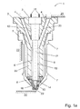
- Fig. 1 a shows a schematic sectional view of an embodiment of a diecasting nozzle 1 according to the invention with a heating cartridge 2 which is contacted by electrical connections 11, a channel support 3, into which the melt ducts 4 embodied in duplicate in the illustrated embodiment are introduced, a nozzle body 5 which houses the duct support 3
- the melt channels 4 extend from an eccentric inlet position of the melt from the melt distributor to a central bore in the nozzle shaft 33, the heating zone 6, and are in a preferred embodiment by a Channel coating 20 protected from the adverse, especially corrosive effects of the melt.
- a steel channel carrier 3 can not alloy with the melt, nor be damaged in any other way by this.
- enamel is used in the particularly preferred embodiment.
- the melt channels 4 are formed in such a way that they match the in the Fig. 1 only indicated melt distributor 21 are connectable and are supplied by this with the melt.
- the melt channels 4 open into the heating zone 6, which is also part of the melt channel 4 and into which the heating cartridge 2 protrudes with the heating area 17. As a result, the melt, when it is in the heating zone 6 in the nozzle shaft 33, can be heated.
- the heating cartridge 2 is also provided in an alternative embodiment with a coating 13, similar to the channel coating 20, the relevant Protects surfaces from corrosion, adhesion of melt or unwanted alloy with this. This is especially true when it is a heating cartridge 2, which is not made of ceramic.
- the die-casting nozzle 1 further has a direction in the direction of FIG. 1 only indicated mold 22 to the channel support 3 subsequent nozzle tip 8.
- the nozzle tip 8 has, in its center, a region tapering towards the sprue point 23 in which the melt is oriented towards the exit from the die casting nozzle 1 at the sprue area 10.
- the nozzle tip 8 is made interchangeable in the preferred embodiment, so that this highly loaded component can easily be replaced when worn without having to take the entire die casting nozzle 1 out of operation.
- Particularly preferred is the use of a very wear-resistant material, such as a ceramic, for the production of the nozzle tip 8.
- a particularly long life despite the high load is ensured by the emerging at high speed through the sprue 10 melt.
- the melt-carrying region, the channel carrier 3, is insulated.
- the insulation is preferably carried out by the nozzle body 5, the heat transfer is reduced to the mold 22, since the nozzle tip 1 is supported only in the region of the support rings 7 on the mold 22.
- a further reduction of the heat transfer takes place through the use of an insulator 9 between channel carrier 3 and nozzle body 5. This can also serve air.
- the permanently secure and firm hold of the heating element 2 in the channel carrier 3 is secured by a seat 12 of a centering guide.
- the end of the heating cartridge 2 facing towards the sprue point 23 is formed by the preferably conical tip region 18.
- the melt cools in this space of the sprue area 10
- it forms a tight plug which prevents leakage or backflow of the melt and does not dissolve out of the sprue area 10 even if it melts when the heating begins and separates from the walls.
- the melting itself takes place very fast and uniform, since the preferred hollow cone shape of the plug has a small wall thickness than a solid profile and can be heated quickly.
- the very rapid solidification of the plug is promoted by the fact that the flowing through the narrow space in the runner 10 melt heats itself during the flow by friction itself and still remains flowable at an incipient cooling of the tip portion 18 during the flow. On the other hand, if the melt flow stops, frictional heat no longer occurs and the melt solidifies immediately to the stopper closing the gate 10.
- the heating area 17 of the heating cartridge 2 is heated, so that the temperature of the melt in the heating zone 6 likewise increases.
- the heat is conducted on the one hand via the melt for grafting and on the other hand through the zone of the cross-sectional change 14 to the tip region 18.
- About the formation of the cross-sectional change 14 can be influenced to what extent the heat flows over to the tip region 18.
- the time of melting depending on the temperature, which reaches the heating area 17, influenced.
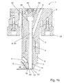
- Fig. 1b shows a schematic sectional view of another embodiment of a die casting nozzle 1 'according to the invention with cartridge heating means of heating cartridge 2'.
- the heating cartridge 2 ' in this case has a head 44 which is formed cylindrically and is pressed by a expansion bolt 39 in conjunction with a pressure screw 40 against a seat 12' in a bore of the channel carrier 3.
- the pressure screw 40 generates a bias of the expansion pin 39, connected to a force on the head 44 of the heating element 2 '.
- the prestressed expansion pin 39 which expands as much as the channel support 3 in an expansion region and a relaxation of the seat 12 'counteracts.
- the expansion area extends from the seat 12 'to the end of the thread in a form-fitting with the channel carrier 3 slot nut into which the pressure screw 40 engages. Rather, the prestressed by the pressure screw 40 in the seat 12 'registered bias is maintained and the heating element 2 remains with its head 44 firmly in its seat 12'.
- a support ring 7 and thrust pieces 38 are provided. With these elements, the die-cast nozzle 1 'is supported on the casting mold 22 during the casting processes, when it touches the casting mold 22 during the casting process. By only selective touchdown and the use of materials with low thermal conductivity of the heat flow from the die casting nozzle 1 'is reduced in the mold 22.
- an insulator 9 preferably an air space, is furthermore provided for this purpose.
- an insulating element for example a disk, consisting of titanium, for arrangement in the region of the end face 43 of the nozzle tip 8 is provided in order to avoid the outflow of heat directly into the gate region of the casting mold.
- a cross-sectional change 14, here in cross section of the melt channel 4, ensures defined heat transfer via the melt into the sprue area 10 of the nozzle tip 8.
- a change in the cross section of the heating cartridge 2 is also appropriate Fig. 1a , intended.
- a further cross-sectional change in the form of the tear-off edge 42 is provided. This not only reduces the heat flow into the casting mold via the melt, but also provides a predetermined breaking point for the cooled melt, at which the shrinking during cooling, solidified melt breaks off the article before the molding process.
- an inner insert, preferably made of a durable ceramic or tungsten, in the runner 10 is advantageous because the flowing there at high speed melt would otherwise cause severe wear.
- thermosensor 41 has proved to be particularly advantageous. In the preferred embodiment, this is arranged near the sprue area 10 in the nozzle tip 8, which is preferably made of insulating titanium.
- the temperature measurement that the thermosensor 41 supplies is preferably processed in a control device. This then provides a time-dependent exact temperature control in each section of the die casting process with the result of an effective use of energy and a minimum thermal load of the melt-carrying elements. This makes it possible to dispense with special measures to avoid thermal wear or an undesirable alloy, such as a coating.
- the melt channel 4 runs from the connection area with the melt distributor deviating from the vertical through the channel carrier 3 until it hits the heating zone 6, which receives the heating cartridge 2, and continues in the heating zone 6 to the nozzle tip 8.
- the heating region 17 and the tip region 18 merge into one another without changing the cross section of the heating cartridge 2.
- the inner insert 31 reduces wear and increases the service life of the nozzle tip 8.
- Fig. 2 shows a schematic representation of an embodiment of a heating element 2 according to the invention in partial section, showing the heating area 17.
- a multi-layer structure of the heater can be seen, which in the particularly preferred embodiment has centrally as a core and at the periphery and for the isolation of the conductive regions from each other an insulator ceramic 15.
- the conductor ceramic 16 Embedded between these concentric layers in the embodiment shown is the conductor ceramic 16, which serves as a heater by means of its electrically conductive properties.
- the individual conductor loops are electrically insulated against each other by isolator ceramic 15.
- Cartridge 2 made of high-performance ceramics are particularly suitable for die-cast nozzles with short cycle times, which must be heated with rapidly changing heat demand.
- the materials used in the preferred embodiment of the heating cartridge 2 known in the prior art ceramics are used, which are characterized by many advantages compared to metallic heating elements.
- the high surface power of up to 150 W / cm 2 and the radiation emission of e> 0.9 prove particularly favorable, whereby temperatures of up to 1000 ° C. can be achieved, which is particularly suitable for high-melting non-ferrous metals such as aluminum, which are processed by die-casting that is of interest.
- the all-ceramic heating elements are resistant to oxidation and acids. They have a low wettability with liquid metals, high mechanical strength, good thermal conductivity and at the same time a high electrical insulation resistance and a high dielectric strength. At the same time they are characterized by high hardness and wear resistance.
- the heating element 2 Due to the good and safe electrical insulation to the outside, the heating element 2 with higher voltages, preferably 230 V, operable. This has the advantage that a low current must be passed to the heater and the cross-sections of the leads can be correspondingly low. Cost savings and low power losses are the consequences. With a preferred power of 400 W only a current of 1.8 A is required.
- the electrically conductive ceramic and the sheath of insulating ceramic are sintered into a homogeneous body and therefore enables very high power densities with high mechanical stability.
- the good aging and wear resistance of ceramics guarantees a long service life even at high temperatures.
- a coating 13, preferably enamel, is required to produce corresponding, primarily occluding properties of the surface.
- the aim is to prevent oxidation under the influence of the aggressive melt and a low tendency of metals to adhere to the surface.
- the heating cartridge is alternatively made of a ceramic with at least one introduced in this metallic conductor, wherein the metallic conductor is prepared as a metal powder, preferably high-melting, as a solid conductor or in a lithographic process and introduced as a film.
- the metallic conductor is prepared as a metal powder, preferably high-melting, as a solid conductor or in a lithographic process and introduced as a film.
- methods such as thick-film technology, HTCC or LTCC are preferably provided.
- a particularly preferred embodiment of the heating cartridge 2 provides a separate heating in the heating area 17 and in the tip area 18, which are also controlled separately via the electrical connections 11, 11 '.
- the heating area 17 can be continuously supplied with so much energy that the melt remains liquid.
- the tip region 18 can be heated and cooled in a targeted manner in a timed manner so that the solidification and remelting of the small amount of melt located in the vicinity of the tip region 18 is made possible.
- the cross-sectional change 14 the mutual influence of the heating area 17 and the tip area 18 is minimized and supports the self-sufficient function of both areas.
- the shank 19, which is shown interrupted, preferably has such a great length that it projects upwards out of the melt distributor, the contacts 11, 11 'are easily accessible and cable routing through the melt distributor is avoided.
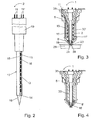
- Fig. 3 shows a schematic sectional view of an embodiment of a diecasting nozzle 1 according to the invention with cartridge and shaft tip heater and side gating 34, here with Angusszzir 24 in star shape, for the production of articles 29.
- a nozzle shaft 33 is used, which is directly heated and
- a structure of insulating ceramic 15 and conductor ceramic 16 has, similar to the previously described heating element 2.
- both the nozzle shaft 33 'together with the nozzle tip 8' is made in one piece and can be heated.
- the largest part of the heating power in the area of the nozzle tip 8 ', particularly preferably in the first 1 to 15 millimeters from the starting point 23, is produced. In this case, so much heating power is entered that the heat loss in the front of the nozzle is compensated. This depends on external factors such as thermal insulation and heat dissipation interfaces.
- the electrical connection 11, 11 ' takes place from the outside, for example via the top plate 35, where the die-casting nozzle 1 is in contact with the melt distributor.
- an overall excessively high melt temperature in the region of the heating cartridge 2 can be counteracted by operating it at a lower temperature or being entirely unheated. It is therefore not necessary to ensure that sufficient heat flows into the tip region 18. Rather, the temperature conditions in the area of the nozzle tip 8 alone can be purposefully influenced.
- this cylinder retains the full diameter to the gate point 23 and there in such a way the ring diameter of the sprue 25 from Fig. 6 increases that the production of several parts is simplified by lateral injection or parts of larger dimensions can be produced.
- an enlargement of the diameter of the heating cartridge 2 in the tip region 18 is provided.
- a solution is given the particular advantage in which the entire die casting nozzle 1 in the outer region of a nozzle body 5 has a jacket made of titanium or at least with an air layer insulating the nozzle shaft 33 'out.
- Fig. 4 shows a schematic sectional view of an embodiment of a die-cast nozzle 1 according to the invention with cartridge and top heater.
- a nozzle shaft 33 is used, which is not heated.
- a separate nozzle tip 8 ' is provided, which by a ceramic structure according to the above description also conductive and insulating ceramics has and thus is heated.
- the electrical connection, which is necessary for this, is preferably introduced through the nozzle shaft 33 to the top plate 35 or passed directly through the nozzle body 5 to the outside.
- a heating ceramic is needed.
- the tip region 18 is designed to be heatable.
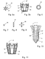
- Fig. 5a shows a schematic plan view of a sprue scheme of a die casting nozzle according to the invention in star shape 24 and side sprue 34. Also indicated is an article 29, a product of the proposed die casting process. This is produced by means of the star shape 24 of the sprue in lateral gating 34.
- the star-shaped sprue structure 24 shown by way of example, there are six articles 29 which can be manufactured in one go.
- Fig. 5b shows with the nozzle tip 8 "is a schematic sectional view of a detail of an embodiment of a die-casting nozzle according to the invention with lateral gating 34, wherein the gate point is closed by a nozzle closure 37.
- a nozzle tip, a nozzle ring or a nozzle bar depending on the concrete shape of the structure of the nozzle tip ", both heated and unheated variant, provided.
- a separate nozzle closure 37 is also included as an integrally manufactured nozzle tip without opening in the gate. Breakthroughs in the wall of the nozzle tip 8 "are provided as a side gate 36 for the exit of the melt in the laterally arranged sprue area of the mold, not shown.
- Fig. 6 shows a schematic plan view of a sprue of a die-casting nozzle according to the invention in annular form 25.
- a shape is formed when, as for example in Fig. 1 shown, the tip portion 18 to the gate point 23rd zoom ranges. If a larger ring diameter is required, this can be achieved by a larger diameter of the tip region 18 at the starting point 23.
- Fig. 7 shows a schematic plan view of a sprue of a diecast nozzle according to the invention in dot form 26.
- a dot shape 26 is in contrast to in Fig. 6 shown ring shape 25 achieved when no tip portion 18 according to Fig. 1 exists and instead, such as in FIG. 10 illustrated, the blunt heating cartridge 2 'does not reach into the nozzle tip 8 into it.
- FIGS. 8 and 9 show a schematic plan view of a sprue of a diecast nozzle according to the invention in a flat shape 27 or in a cross shape 28.
- the basic structure of the die-casting nozzle corresponds to that FIG. 7
- the shape of the sprue 23 as a flat shape 27 results from a corresponding shape of the nozzle tip 8.
- Particularly advantageous is a flat shape 27 for articles with large longitudinal extent. A more uniform material outflow of the melt in four directions, however, results when using the cross shape 28th
- the abovementioned sprue contours are caused in each case by an exchangeable tungsten plate having the corresponding sprue contour, which is applied to the nozzle at the sprue point 23.
- various sprue contours can be applied without replacing the die casting nozzle 1 as a whole.
- Fig. 10 shows a schematic sectional view of an embodiment of a die-casting nozzle 1 according to the invention with helical tube 30.
- the entire nozzle body 5 can be heated in the outer region.
- the helical tube 30 is placed around the outer sheath.
- Fig. 11 shows a schematic sectional view of a detail of an embodiment of a die-cast nozzle according to the invention with top heating and inner insert 31, embodied as Bankkeramikdüse 32.
- the construction of insulator ceramic 15 and conductor ceramic 16 results in a high conductor density in this area, by which a high heating power can be entered into this area.
- the nozzle tip 8 ' represents only a very small amount of material compared to the other components of the die casting nozzle, so that heating and cooling are possible here with a very high dynamics and rapid cycle change.
- the power density is adjustable for each region by the cross-section of the conductive regions of the conductor ceramic 16, and by appropriate doping. For exact shaping, these parts are over-turned after firing, with a layer of insulator ceramic 15 always remaining outside.
- a coating is used here, but particularly preferably an inner insert 31.
- This consists in particular of tungsten, but also other materials with high resistance to wear, high melting point and good thermal conductivity, such as a thermally conductive ceramic, are used.
- a closure-reducing inner liner 31 is particularly important.
- a nozzle tip 8 'made of ceramic in turn very stable, wear-resistant and not to chemical bonds or alloys tending material to dispense with the inner liner 31.
- An outer insulation is provided in preferred embodiments of both variants in order to avoid the heat flow from the die-casting nozzle.
- the reduction in wear is carried out additionally or alternatively to the aforementioned measures by a special process management. It has proven to be advantageous if the performance of the heatable elements in the gate area is controlled in such a way that the wear of the gate area is minimized.
- the control device only delivers the power required to melt the melt plug in the sprue area. This further reduces the wear of the die-cast nozzle in the sprue area.
- the control of the heating power is carried out according to the material of the melt and other parameters of the die casting nozzle, such as the gate geometry.
- a control processes measured values from sensors and thus determines the heating power accordingly.
- sensors temperature sensors in the area of the diecasting nozzle, but also other sensors, such as pressure sensors in the melt channel, are provided.
- temperature sensors in the region of the melt channel on the inside and / or on its outside wall are particularly preferred and pressure sensors in the interior of the melt channel 4 or in the sprue area 10 are used alternatively or in addition, for example in US Pat Fig. 1 shown.
- the sprue-less die-cast hot runner system which has the diecasting nozzle according to the invention, also allows well reproducible conditions, resulting in a high, consistent casting quality.
- the wall thicknesses of the casting can be minimized with appropriate material savings by this increased quality with appropriate weight and material savings.
Landscapes
- Engineering & Computer Science (AREA)
- Mechanical Engineering (AREA)
- Moulds For Moulding Plastics Or The Like (AREA)
- Molds, Cores, And Manufacturing Methods Thereof (AREA)
- Injection Moulding Of Plastics Or The Like (AREA)
- Casting Support Devices, Ladles, And Melt Control Thereby (AREA)
- Ink Jet (AREA)
Priority Applications (1)
| Application Number | Priority Date | Filing Date | Title |
|---|---|---|---|
| PL12823137T PL2782692T3 (pl) | 2011-11-15 | 2012-11-15 | Ciśnieniowa dysza odlewnicza i sposób operowania ciśnieniową dyszą odlewniczą oraz element grzewczy i wkład grzewczy |
Applications Claiming Priority (3)
| Application Number | Priority Date | Filing Date | Title |
|---|---|---|---|
| DE102011055398 | 2011-11-15 | ||
| DE102012102549A DE102012102549A1 (de) | 2011-11-15 | 2012-03-26 | Druckgussdüse und Verfahren zum Betrieb der Druckgussdüse |
| PCT/DE2012/100349 WO2013071926A2 (de) | 2011-11-15 | 2012-11-15 | Druckgussdüse und verfahren zum betrieb einer druckgussdüse |
Publications (2)
| Publication Number | Publication Date |
|---|---|
| EP2782692A2 EP2782692A2 (de) | 2014-10-01 |
| EP2782692B1 true EP2782692B1 (de) | 2015-06-17 |
Family
ID=48145272
Family Applications (1)
| Application Number | Title | Priority Date | Filing Date |
|---|---|---|---|
| EP12823137.0A Active EP2782692B1 (de) | 2011-11-15 | 2012-11-15 | Druckgussdüse und verfahren zum betrieb einer druckgussdüse sowie heizelement und heizpatrone per se |
Country Status (11)
| Country | Link |
|---|---|
| US (1) | US9561540B2 (enExample) |
| EP (1) | EP2782692B1 (enExample) |
| KR (1) | KR20140109872A (enExample) |
| CN (1) | CN104114302B (enExample) |
| BR (1) | BR112014011557B1 (enExample) |
| CA (1) | CA2855799C (enExample) |
| DE (2) | DE102012102549A1 (enExample) |
| ES (1) | ES2546318T3 (enExample) |
| IN (1) | IN2014CN04396A (enExample) |
| PL (1) | PL2782692T3 (enExample) |
| WO (1) | WO2013071926A2 (enExample) |
Cited By (2)
| Publication number | Priority date | Publication date | Assignee | Title |
|---|---|---|---|---|
| EP3302851B1 (de) | 2015-06-05 | 2022-08-03 | Oskar Frech GmbH + Co. KG | Angusssystem für eine druckgiessform |
| DE102021111538A1 (de) | 2021-05-04 | 2022-11-10 | Nemak, S.A.B. De C.V. | Gießvorrichtung und Verfahren zum Gießen |
Families Citing this family (16)
| Publication number | Priority date | Publication date | Assignee | Title |
|---|---|---|---|---|
| AT515970B1 (de) * | 2014-07-03 | 2018-11-15 | Ltc Gmbh | Verfahren und Vorrichtung zum Gießen zumindest eines Bauteils |
| DE102014018798A1 (de) | 2014-12-19 | 2016-06-23 | Gebr. Krallmann Gmbh | Fördervorrichtung für eine Metallschmelze in einem Spritzgussaggregat |
| DE102015100861B4 (de) | 2015-01-21 | 2018-07-19 | TransMIT Gesellschaft für Technologietransfer mbH | Heißkanal für eine Druckgussvorrichtung und Betriebsverfahren dafür |
| GB2543517A (en) * | 2015-10-20 | 2017-04-26 | Pyrotek Eng Mat Ltd | Caster tip for a continuous casting process |
| DE102015224410B4 (de) * | 2015-12-07 | 2020-11-19 | Volkswagen Aktiengesellschaft | Düse für Metall-Druckgussanwendungen |
| DE112016006531A5 (de) | 2016-03-01 | 2018-12-06 | Ferrofacta Gmbh | Druckgussdüsensystem |
| CN105881717B (zh) * | 2016-05-26 | 2018-04-06 | 宁夏机械研究院股份有限公司 | 陶瓷喷嘴等静压成型模具 |
| CN110666132B (zh) * | 2019-09-26 | 2021-05-28 | 清苑县华通金属炉料有限公司 | 一种基于铝锭成型的容错性强的压铸模具 |
| CN110695335B (zh) * | 2019-10-24 | 2025-02-07 | 上海五腾金属制品有限公司 | 一种实现镁合金射出成型的装置及方法 |
| DE102019220217A1 (de) * | 2019-12-19 | 2021-06-24 | Robert Bosch Gmbh | Tragbares Multischmelzgerät und Vorrichtung mit einem tragbaren Multischmelzgerät |
| WO2022029300A1 (de) * | 2020-08-06 | 2022-02-10 | Sms Group Gmbh | VAKUUM-INDUKTIONS-GIEßEINRICHTUNG ZUM GIEßEN VON METALL UND METALLLEGIERUNGEN UNTER VAKUUM UND/ODER SCHUTZGASATMOSPHÄRE SOWIE VERFAHREN ZUM WECHSELN EINER STOPFENSTANGE UND/ODER EINES VERSCHLUSSKÖRPERS EINER STOPFENGIEßVORRICHTUNG AN EINER VAKUUM-INDUKTIONS-GIEßEINRICHTUNG |
| US20220111434A1 (en) * | 2020-10-08 | 2022-04-14 | Wagstaff, Inc. | Material, apparatus, and method for refractory castings |
| DE102020215665A1 (de) | 2020-12-10 | 2022-06-15 | Oskar Frech Gmbh + Co. Kg | Druckgießmaschine mit Absperrventil im Schmelzeeinlasskanal und Betriebsverfahren |
| DE102021132870A1 (de) | 2021-12-14 | 2023-06-15 | Ferrofacta Gmbh | Druckgussform, Warmkammersystem, Verfahren für den Druckguss von Metall und Verwendung einer Druckgussform |
| CN115744916B (zh) * | 2022-12-05 | 2025-11-28 | 江苏中圣压力容器装备制造有限公司 | 带多喷嘴分布器的高效冷氢化反应器 |
| US20240357712A1 (en) | 2023-04-21 | 2024-10-24 | Wagstaff, Inc. | Material, apparatus, and method for electrically shielding heated components |
Family Cites Families (19)
| Publication number | Priority date | Publication date | Assignee | Title |
|---|---|---|---|---|
| US4161386A (en) * | 1977-12-19 | 1979-07-17 | Incoe Corporation | Nozzle for injection molding machines |
| US4635851A (en) * | 1983-09-19 | 1987-01-13 | Pegasus Industries, Inc. | Casting nozzle |
| DE3335280A1 (de) | 1983-09-29 | 1985-04-18 | EWIKON Entwicklung und Konstruktion GmbH & Co KG, 4900 Herford | Elektrisch betriebenes heizelement zum aufheizen von materialschmelzen in einem heisskanalwerkzeug |
| US4638849A (en) * | 1985-08-25 | 1987-01-27 | Vsi Corporation | Nozzle assembly for die casting apparatus |
| JPH0710546B2 (ja) * | 1990-11-09 | 1995-02-08 | プラストロン株式会社 | 加熱装置を有するゲート装置 |
| US5448678A (en) * | 1991-04-26 | 1995-09-05 | Booton; Harold | Electrically heated nozzle for die casting |
| US5315686A (en) * | 1991-04-26 | 1994-05-24 | William Caugherty | Electrically heated nozzle for die casting |
| CA2057439C (en) * | 1991-12-11 | 2000-02-08 | Jobst Ulrich Gellert | Method of manufacturing an injection molding probe |
| DE19531161C2 (de) * | 1995-08-24 | 1999-05-20 | Frech Oskar Gmbh & Co | Warmkammer-Druckgießmaschine |
| US6394784B1 (en) * | 2000-03-08 | 2002-05-28 | Mold-Masters Limited | Compact cartridge hot runner nozzle |
| DE50012864D1 (de) | 2000-10-31 | 2006-07-06 | Frech Oskar Gmbh & Co | Einrichtung zur Herstellung von Metall-Druckgussteilen, insbesondere aus NE-Metallen |
| CA2453170C (en) * | 2002-12-20 | 2012-02-21 | Mold-Masters Limited | Lateral gating injection molding apparatus |
| DE102005014566B4 (de) * | 2005-03-17 | 2010-07-22 | Kraussmaffei Technologies Gmbh | Thermoverschlussdüse und Verfahren zum Beheizen einer solchen |
| DE102005042867A1 (de) * | 2005-09-08 | 2007-03-22 | Bühler Druckguss AG | Druckgiessverfahren |
| DE102006002341A1 (de) * | 2006-01-18 | 2007-07-26 | Kompetenzzentrum Neue Materialien Nordbayern Gmbh | Spritzgießwerkzeug |
| US20080017345A1 (en) * | 2006-07-20 | 2008-01-24 | Husky Injection Molding Systems Ltd. | Molding-system valve |
| US7614869B2 (en) * | 2007-05-08 | 2009-11-10 | Mold-Masters (2007) Limited | Manifold nozzle connection for an injection molding system |
| CN201633176U (zh) * | 2010-01-15 | 2010-11-17 | 李承哲 | 一种针阀式单嘴注塑的热机嘴 |
| DE102011050149A1 (de) * | 2010-11-17 | 2012-05-24 | Ferrofacta Gmbh | Druckgussdüse und Druckgussverfahren |
-
2012
- 2012-03-26 DE DE102012102549A patent/DE102012102549A1/de not_active Withdrawn
- 2012-11-15 DE DE112012004748.6T patent/DE112012004748A5/de not_active Withdrawn
- 2012-11-15 PL PL12823137T patent/PL2782692T3/pl unknown
- 2012-11-15 US US14/357,774 patent/US9561540B2/en active Active
- 2012-11-15 CN CN201280056239.XA patent/CN104114302B/zh active Active
- 2012-11-15 CA CA2855799A patent/CA2855799C/en active Active
- 2012-11-15 EP EP12823137.0A patent/EP2782692B1/de active Active
- 2012-11-15 KR KR1020147014963A patent/KR20140109872A/ko not_active Ceased
- 2012-11-15 ES ES12823137.0T patent/ES2546318T3/es active Active
- 2012-11-15 WO PCT/DE2012/100349 patent/WO2013071926A2/de not_active Ceased
- 2012-11-15 IN IN4396CHN2014 patent/IN2014CN04396A/en unknown
- 2012-11-15 BR BR112014011557-5A patent/BR112014011557B1/pt active IP Right Grant
Cited By (2)
| Publication number | Priority date | Publication date | Assignee | Title |
|---|---|---|---|---|
| EP3302851B1 (de) | 2015-06-05 | 2022-08-03 | Oskar Frech GmbH + Co. KG | Angusssystem für eine druckgiessform |
| DE102021111538A1 (de) | 2021-05-04 | 2022-11-10 | Nemak, S.A.B. De C.V. | Gießvorrichtung und Verfahren zum Gießen |
Also Published As
| Publication number | Publication date |
|---|---|
| WO2013071926A2 (de) | 2013-05-23 |
| CA2855799C (en) | 2017-04-18 |
| IN2014CN04396A (enExample) | 2015-09-04 |
| WO2013071926A3 (de) | 2014-09-04 |
| CA2855799A1 (en) | 2013-05-23 |
| US9561540B2 (en) | 2017-02-07 |
| EP2782692A2 (de) | 2014-10-01 |
| KR20140109872A (ko) | 2014-09-16 |
| DE112012004748A5 (de) | 2014-09-25 |
| CN104114302A (zh) | 2014-10-22 |
| ES2546318T3 (es) | 2015-09-22 |
| BR112014011557A2 (pt) | 2017-05-09 |
| HK1198527A1 (en) | 2015-05-15 |
| CN104114302B (zh) | 2016-10-19 |
| DE102012102549A1 (de) | 2013-05-16 |
| PL2782692T3 (pl) | 2015-10-30 |
| BR112014011557B1 (pt) | 2019-06-04 |
| US20140319188A1 (en) | 2014-10-30 |
Similar Documents
| Publication | Publication Date | Title |
|---|---|---|
| EP2782692B1 (de) | Druckgussdüse und verfahren zum betrieb einer druckgussdüse sowie heizelement und heizpatrone per se | |
| EP1201335B1 (de) | Einrichtung zur Herstellung von Metall-Druckgussteilen, insbesondere aus NE-Metallen | |
| EP3302851B1 (de) | Angusssystem für eine druckgiessform | |
| EP2640537B1 (de) | Druckgussdüse und druckgussverfahren | |
| DE10080726B4 (de) | Form für eine Heißanguß-Spritzmaschine sowie Verfahren zum Herstellen derselben | |
| DE69832538T2 (de) | Magnesiumdruckguss | |
| DE10356937A1 (de) | Düsenspitze und -dichtung | |
| US6470956B2 (en) | Method and apparatus for semi-molten metal injection molding | |
| EP1934005B1 (de) | Druckgiessverfahren | |
| DE102015100861B4 (de) | Heißkanal für eine Druckgussvorrichtung und Betriebsverfahren dafür | |
| EP3423215B1 (de) | Druckgussdüsensystem | |
| WO2007048260A1 (de) | Druckgiessverfahren und vorrichtung zum druckgiessen | |
| AT515969B1 (de) | Vorrichtung und Verfahren zur Erstellung zumindest eines metallischen Bauteils | |
| DE102006002342A1 (de) | Werkzeug | |
| DE102006002341A1 (de) | Spritzgießwerkzeug | |
| JP4359826B2 (ja) | 金属材料成形装置 | |
| CH570216A5 (en) | Continuous casting using stepwise extrusion of the billet - in horizontal, water-cooled die with very accurate temp. control | |
| DE10039591A1 (de) | Verfahren und Vorrichtung zum Druckgießen von metallischen Formkörpern | |
| HK1198527B (en) | Diecasting nozzle and method for operating a diecasting nozzle | |
| WO2016019946A1 (de) | Giessventil und giessvorrichtung |
Legal Events
| Date | Code | Title | Description |
|---|---|---|---|
| PUAI | Public reference made under article 153(3) epc to a published international application that has entered the european phase |
Free format text: ORIGINAL CODE: 0009012 |
|
| 17P | Request for examination filed |
Effective date: 20140611 |
|
| AK | Designated contracting states |
Kind code of ref document: A2 Designated state(s): AL AT BE BG CH CY CZ DE DK EE ES FI FR GB GR HR HU IE IS IT LI LT LU LV MC MK MT NL NO PL PT RO RS SE SI SK SM TR |
|
| R17D | Deferred search report published (corrected) |
Effective date: 20140904 |
|
| GRAP | Despatch of communication of intention to grant a patent |
Free format text: ORIGINAL CODE: EPIDOSNIGR1 |
|
| INTG | Intention to grant announced |
Effective date: 20150109 |
|
| GRAS | Grant fee paid |
Free format text: ORIGINAL CODE: EPIDOSNIGR3 |
|
| GRAA | (expected) grant |
Free format text: ORIGINAL CODE: 0009210 |
|
| AK | Designated contracting states |
Kind code of ref document: B1 Designated state(s): AL AT BE BG CH CY CZ DE DK EE ES FI FR GB GR HR HU IE IS IT LI LT LU LV MC MK MT NL NO PL PT RO RS SE SI SK SM TR |
|
| DAX | Request for extension of the european patent (deleted) | ||
| REG | Reference to a national code |
Ref country code: GB Ref legal event code: FG4D Free format text: NOT ENGLISH |
|
| REG | Reference to a national code |
Ref country code: CH Ref legal event code: EP |
|
| REG | Reference to a national code |
Ref country code: AT Ref legal event code: REF Ref document number: 731618 Country of ref document: AT Kind code of ref document: T Effective date: 20150715 |
|
| REG | Reference to a national code |
Ref country code: IE Ref legal event code: FG4D Free format text: LANGUAGE OF EP DOCUMENT: GERMAN |
|
| REG | Reference to a national code |
Ref country code: DE Ref legal event code: R096 Ref document number: 502012003526 Country of ref document: DE |
|
| REG | Reference to a national code |
Ref country code: SE Ref legal event code: TRGR Ref country code: ES Ref legal event code: FG2A Ref document number: 2546318 Country of ref document: ES Kind code of ref document: T3 Effective date: 20150922 |
|
| PG25 | Lapsed in a contracting state [announced via postgrant information from national office to epo] |
Ref country code: LT Free format text: LAPSE BECAUSE OF FAILURE TO SUBMIT A TRANSLATION OF THE DESCRIPTION OR TO PAY THE FEE WITHIN THE PRESCRIBED TIME-LIMIT Effective date: 20150617 Ref country code: NO Free format text: LAPSE BECAUSE OF FAILURE TO SUBMIT A TRANSLATION OF THE DESCRIPTION OR TO PAY THE FEE WITHIN THE PRESCRIBED TIME-LIMIT Effective date: 20150917 Ref country code: HR Free format text: LAPSE BECAUSE OF FAILURE TO SUBMIT A TRANSLATION OF THE DESCRIPTION OR TO PAY THE FEE WITHIN THE PRESCRIBED TIME-LIMIT Effective date: 20150617 Ref country code: FI Free format text: LAPSE BECAUSE OF FAILURE TO SUBMIT A TRANSLATION OF THE DESCRIPTION OR TO PAY THE FEE WITHIN THE PRESCRIBED TIME-LIMIT Effective date: 20150617 |
|
| REG | Reference to a national code |
Ref country code: PL Ref legal event code: T3 |
|
| REG | Reference to a national code |
Ref country code: FR Ref legal event code: PLFP Year of fee payment: 4 |
|
| REG | Reference to a national code |
Ref country code: LT Ref legal event code: MG4D Ref country code: NL Ref legal event code: MP Effective date: 20150617 |
|
| PG25 | Lapsed in a contracting state [announced via postgrant information from national office to epo] |
Ref country code: GR Free format text: LAPSE BECAUSE OF FAILURE TO SUBMIT A TRANSLATION OF THE DESCRIPTION OR TO PAY THE FEE WITHIN THE PRESCRIBED TIME-LIMIT Effective date: 20150918 Ref country code: RS Free format text: LAPSE BECAUSE OF FAILURE TO SUBMIT A TRANSLATION OF THE DESCRIPTION OR TO PAY THE FEE WITHIN THE PRESCRIBED TIME-LIMIT Effective date: 20150617 Ref country code: LV Free format text: LAPSE BECAUSE OF FAILURE TO SUBMIT A TRANSLATION OF THE DESCRIPTION OR TO PAY THE FEE WITHIN THE PRESCRIBED TIME-LIMIT Effective date: 20150617 Ref country code: BG Free format text: LAPSE BECAUSE OF FAILURE TO SUBMIT A TRANSLATION OF THE DESCRIPTION OR TO PAY THE FEE WITHIN THE PRESCRIBED TIME-LIMIT Effective date: 20150917 |
|
| PG25 | Lapsed in a contracting state [announced via postgrant information from national office to epo] |
Ref country code: EE Free format text: LAPSE BECAUSE OF FAILURE TO SUBMIT A TRANSLATION OF THE DESCRIPTION OR TO PAY THE FEE WITHIN THE PRESCRIBED TIME-LIMIT Effective date: 20150617 |
|
| PG25 | Lapsed in a contracting state [announced via postgrant information from national office to epo] |
Ref country code: RO Free format text: LAPSE BECAUSE OF NON-PAYMENT OF DUE FEES Effective date: 20150617 Ref country code: IS Free format text: LAPSE BECAUSE OF FAILURE TO SUBMIT A TRANSLATION OF THE DESCRIPTION OR TO PAY THE FEE WITHIN THE PRESCRIBED TIME-LIMIT Effective date: 20151017 Ref country code: PT Free format text: LAPSE BECAUSE OF FAILURE TO SUBMIT A TRANSLATION OF THE DESCRIPTION OR TO PAY THE FEE WITHIN THE PRESCRIBED TIME-LIMIT Effective date: 20151019 Ref country code: SK Free format text: LAPSE BECAUSE OF FAILURE TO SUBMIT A TRANSLATION OF THE DESCRIPTION OR TO PAY THE FEE WITHIN THE PRESCRIBED TIME-LIMIT Effective date: 20150617 |
|
| REG | Reference to a national code |
Ref country code: DE Ref legal event code: R097 Ref document number: 502012003526 Country of ref document: DE |
|
| PLBE | No opposition filed within time limit |
Free format text: ORIGINAL CODE: 0009261 |
|
| STAA | Information on the status of an ep patent application or granted ep patent |
Free format text: STATUS: NO OPPOSITION FILED WITHIN TIME LIMIT |
|
| PG25 | Lapsed in a contracting state [announced via postgrant information from national office to epo] |
Ref country code: DK Free format text: LAPSE BECAUSE OF FAILURE TO SUBMIT A TRANSLATION OF THE DESCRIPTION OR TO PAY THE FEE WITHIN THE PRESCRIBED TIME-LIMIT Effective date: 20150617 |
|
| 26N | No opposition filed |
Effective date: 20160318 |
|
| PG25 | Lapsed in a contracting state [announced via postgrant information from national office to epo] |
Ref country code: LU Free format text: LAPSE BECAUSE OF FAILURE TO SUBMIT A TRANSLATION OF THE DESCRIPTION OR TO PAY THE FEE WITHIN THE PRESCRIBED TIME-LIMIT Effective date: 20151115 Ref country code: MC Free format text: LAPSE BECAUSE OF FAILURE TO SUBMIT A TRANSLATION OF THE DESCRIPTION OR TO PAY THE FEE WITHIN THE PRESCRIBED TIME-LIMIT Effective date: 20150617 |
|
| PG25 | Lapsed in a contracting state [announced via postgrant information from national office to epo] |
Ref country code: SI Free format text: LAPSE BECAUSE OF FAILURE TO SUBMIT A TRANSLATION OF THE DESCRIPTION OR TO PAY THE FEE WITHIN THE PRESCRIBED TIME-LIMIT Effective date: 20150617 |
|
| REG | Reference to a national code |
Ref country code: FR Ref legal event code: PLFP Year of fee payment: 5 |
|
| PG25 | Lapsed in a contracting state [announced via postgrant information from national office to epo] |
Ref country code: SM Free format text: LAPSE BECAUSE OF FAILURE TO SUBMIT A TRANSLATION OF THE DESCRIPTION OR TO PAY THE FEE WITHIN THE PRESCRIBED TIME-LIMIT Effective date: 20150617 |
|
| PG25 | Lapsed in a contracting state [announced via postgrant information from national office to epo] |
Ref country code: HU Free format text: LAPSE BECAUSE OF FAILURE TO SUBMIT A TRANSLATION OF THE DESCRIPTION OR TO PAY THE FEE WITHIN THE PRESCRIBED TIME-LIMIT; INVALID AB INITIO Effective date: 20121115 Ref country code: NL Free format text: LAPSE BECAUSE OF FAILURE TO SUBMIT A TRANSLATION OF THE DESCRIPTION OR TO PAY THE FEE WITHIN THE PRESCRIBED TIME-LIMIT Effective date: 20150617 Ref country code: CY Free format text: LAPSE BECAUSE OF FAILURE TO SUBMIT A TRANSLATION OF THE DESCRIPTION OR TO PAY THE FEE WITHIN THE PRESCRIBED TIME-LIMIT Effective date: 20150617 |
|
| PG25 | Lapsed in a contracting state [announced via postgrant information from national office to epo] |
Ref country code: BE Free format text: LAPSE BECAUSE OF NON-PAYMENT OF DUE FEES Effective date: 20151130 |
|
| PG25 | Lapsed in a contracting state [announced via postgrant information from national office to epo] |
Ref country code: MT Free format text: LAPSE BECAUSE OF FAILURE TO SUBMIT A TRANSLATION OF THE DESCRIPTION OR TO PAY THE FEE WITHIN THE PRESCRIBED TIME-LIMIT Effective date: 20150617 |
|
| REG | Reference to a national code |
Ref country code: FR Ref legal event code: PLFP Year of fee payment: 6 |
|
| PG25 | Lapsed in a contracting state [announced via postgrant information from national office to epo] |
Ref country code: MK Free format text: LAPSE BECAUSE OF FAILURE TO SUBMIT A TRANSLATION OF THE DESCRIPTION OR TO PAY THE FEE WITHIN THE PRESCRIBED TIME-LIMIT Effective date: 20150617 |
|
| PG25 | Lapsed in a contracting state [announced via postgrant information from national office to epo] |
Ref country code: AL Free format text: LAPSE BECAUSE OF FAILURE TO SUBMIT A TRANSLATION OF THE DESCRIPTION OR TO PAY THE FEE WITHIN THE PRESCRIBED TIME-LIMIT Effective date: 20150617 |
|
| PGFP | Annual fee paid to national office [announced via postgrant information from national office to epo] |
Ref country code: DE Payment date: 20241126 Year of fee payment: 13 |
|
| PGFP | Annual fee paid to national office [announced via postgrant information from national office to epo] |
Ref country code: PL Payment date: 20241023 Year of fee payment: 13 |
|
| PGFP | Annual fee paid to national office [announced via postgrant information from national office to epo] |
Ref country code: GB Payment date: 20241107 Year of fee payment: 13 |
|
| PGFP | Annual fee paid to national office [announced via postgrant information from national office to epo] |
Ref country code: FR Payment date: 20241107 Year of fee payment: 13 |
|
| PGFP | Annual fee paid to national office [announced via postgrant information from national office to epo] |
Ref country code: AT Payment date: 20241108 Year of fee payment: 13 |
|
| PGFP | Annual fee paid to national office [announced via postgrant information from national office to epo] |
Ref country code: CZ Payment date: 20241025 Year of fee payment: 13 Ref country code: IE Payment date: 20241107 Year of fee payment: 13 |
|
| PGFP | Annual fee paid to national office [announced via postgrant information from national office to epo] |
Ref country code: IT Payment date: 20241129 Year of fee payment: 13 Ref country code: ES Payment date: 20241213 Year of fee payment: 13 |
|
| PGFP | Annual fee paid to national office [announced via postgrant information from national office to epo] |
Ref country code: SE Payment date: 20241107 Year of fee payment: 13 |
|
| PGFP | Annual fee paid to national office [announced via postgrant information from national office to epo] |
Ref country code: CH Payment date: 20241201 Year of fee payment: 13 |
|
| PGFP | Annual fee paid to national office [announced via postgrant information from national office to epo] |
Ref country code: TR Payment date: 20241106 Year of fee payment: 13 |
|
| REG | Reference to a national code |
Ref country code: CH Ref legal event code: U11 Free format text: ST27 STATUS EVENT CODE: U-0-0-U10-U11 (AS PROVIDED BY THE NATIONAL OFFICE) Effective date: 20251201 |