EP2778293A2 - Steuerungssystem für Baumaschine - Google Patents
Steuerungssystem für Baumaschine Download PDFInfo
- Publication number
- EP2778293A2 EP2778293A2 EP20140159285 EP14159285A EP2778293A2 EP 2778293 A2 EP2778293 A2 EP 2778293A2 EP 20140159285 EP20140159285 EP 20140159285 EP 14159285 A EP14159285 A EP 14159285A EP 2778293 A2 EP2778293 A2 EP 2778293A2
- Authority
- EP
- European Patent Office
- Prior art keywords
- bucket
- working
- mark
- working position
- machine body
- Prior art date
- Legal status (The legal status is an assumption and is not a legal conclusion. Google has not performed a legal analysis and makes no representation as to the accuracy of the status listed.)
- Withdrawn
Links
Images


Classifications
-
- E—FIXED CONSTRUCTIONS
- E02—HYDRAULIC ENGINEERING; FOUNDATIONS; SOIL SHIFTING
- E02F—DREDGING; SOIL-SHIFTING
- E02F3/00—Dredgers; Soil-shifting machines
- E02F3/04—Dredgers; Soil-shifting machines mechanically-driven
- E02F3/28—Dredgers; Soil-shifting machines mechanically-driven with digging tools mounted on a dipper- or bucket-arm, i.e. there is either one arm or a pair of arms, e.g. dippers, buckets
- E02F3/36—Component parts
- E02F3/42—Drives for dippers, buckets, dipper-arms or bucket-arms
- E02F3/43—Control of dipper or bucket position; Control of sequence of drive operations
- E02F3/435—Control of dipper or bucket position; Control of sequence of drive operations for dipper-arms, backhoes or the like
- E02F3/436—Control of dipper or bucket position; Control of sequence of drive operations for dipper-arms, backhoes or the like for keeping the dipper in the horizontal position, e.g. self-levelling
-
- E—FIXED CONSTRUCTIONS
- E02—HYDRAULIC ENGINEERING; FOUNDATIONS; SOIL SHIFTING
- E02F—DREDGING; SOIL-SHIFTING
- E02F9/00—Component parts of dredgers or soil-shifting machines, not restricted to one of the kinds covered by groups E02F3/00 - E02F7/00
- E02F9/26—Indicating devices
- E02F9/261—Surveying the work-site to be treated
-
- E—FIXED CONSTRUCTIONS
- E02—HYDRAULIC ENGINEERING; FOUNDATIONS; SOIL SHIFTING
- E02F—DREDGING; SOIL-SHIFTING
- E02F9/00—Component parts of dredgers or soil-shifting machines, not restricted to one of the kinds covered by groups E02F3/00 - E02F7/00
- E02F9/26—Indicating devices
- E02F9/264—Sensors and their calibration for indicating the position of the work tool
-
- G—PHYSICS
- G01—MEASURING; TESTING
- G01C—MEASURING DISTANCES, LEVELS OR BEARINGS; SURVEYING; NAVIGATION; GYROSCOPIC INSTRUMENTS; PHOTOGRAMMETRY OR VIDEOGRAMMETRY
- G01C9/00—Measuring inclination, e.g. by clinometers, by levels
- G01C9/02—Details
Definitions
- the present invention relates to a construction machine control system, which has a guidance screen to guide buckets with respect to an excavating surface in a case where civil engineering operation is carried by using a construction machine, e.g. a construction machine having a bucket.
- FIG.18 shows a guidance screen 51 disclosed in the Japanese Patent Publication JP-A-2012-255286 as displayed on the display unit (not shown).
- the guidance screen 51 displays a position and a posture of a bucket 54 in three-dimensional display with respect to a working data 52.
- the position and the posture of the bucket 54 which are guiding information for guiding the bucket 54 to target height, are displayed on a window 55
- an azimuth which is the guiding information for making the bucket 54 face directly toward the excavating surface
- a moving direction which is the guiding information for guiding the bucket 54 to target gradient is displayed.
- the working data 52 are stereoscopically displayed on a window 59.
- An operator carries out an excavation operation by controlling the position, the posture, the azimuth, and the moving direction, etc. of the bucket 54 according to the guide, while identifying the present situation based on various types of guiding information displayed on the windows 56 to 59.
- JP-A-2012-255286 discloses a structure that two GPS antennas are used on the construction machine for civil engineering operation, a three-dimensional position coordinates of a rotation center position of an arm is obtained, and a three-dimensional coordinates of a blade edge of a bucket is obtained based on the three-dimensional position coordinates and an directional angle of the arm.
- the construction machine control system comprises a working tool, a working arm for supporting the working tool and for operating the working tool as required, a machine body for supporting the working arm and for being rotatable, a rotating direction acquiring unit provided on the machine body, a control unit having a storage unit and a display unit, wherein the working arm is configured by two or more links with length already known respectively which are connected in a bendable manner, wherein there are further provided a two-axis tilt sensor on the machine body for detecting a horizontal position, a working arm tilt sensor for detecting a tilting of each links of the working arm, and a working tool tilt sensor for detecting a tilting of the working tool, wherein the control unit displays a guidance screen on the display unit based on a working data stored in the storage unit and where a working position and a design gradient are set, based on a direction of the machine body acquired from the rotating direction acquiring unit, and based on detection results of the two-axis tilt sensor, the working
- the rotating direction acquiring unit further comprises a position acquiring means for acquiring absolute coordinates of the machine body, and an operating position of the machine body is acquired by the position acquiring means.
- the position acquiring means is provided on the machine body, absolute coordinates are acquired by the position acquiring means while the machine body rotates, absolute coordinates of a rotation center is acquired based on the absolute coordinates acquired at the time of rotation, and direction of the machine body is acquired from absolute coordinates of the rotation center and from absolute coordinates of the position acquiring means.
- the position acquiring means comprises a prism disposed at a position as required of the machine body, and a total station installed at a known position.
- a working position mark and a bucket mark having predetermined shapes are displayed on the guidance screen as guiding information, a condition of the working tool with respect to the working position is indicated depending on a change of the shape of the bucket mark and on a difference of position with respect to the working position mark, and the working tool is guided to the working position so that the shape and the position of the working position mark and the bucket mark coincide with each other.
- the bucket mark indicates the difference between a design gradient and a gradient of the working tool by the change of shape with respect to the working position mark, and shows the difference between the position of the working tool and the working position by the change of position of the bucket mark with respect to the working position mark.
- the working position mark and the bucket mark are in polygonal shape, two vertexes of polygon of the bucket mark are controlled in a displaceable manner, and the gradient of the working tool with respect to the design gradient is displayed by a distance between the two vertexes.
- the working position mark and the bucket mark are in circular or elliptical shape, the length of one diameter of the bucket mark is constant, the length of a diameter perpendicularly crossing the diameter is controlled variably, and the gradient of the working tool with respect to the design gradient is displayed, depending on the length of the diameter perpendicularly crossing each other.
- the guidance screen further displays numeral value information.
- the guidance screen further displays an arrowmark to indicate a direction of the working position and a rotating direction up to the design gradient.
- the guidance screen further displays a direction of the working tool, a height of the working tool, and the gradient of the working tool.
- the guidance screen further displays a GPS condition.
- the guidance screen further displays the working data.
- the construction machine control system comprises a working tool, a working arm for supporting the working tool and for operating the working tool as required, a machine body for supporting the working arm and for being rotatable, a rotating direction acquiring unit provided on the machine body, a control unit having a storage unit and a display unit, wherein the working arm is configured by two or more links with length already known respectively which are connected in a bendable manner, wherein there are further provided a two-axis tilt sensor on the machine body for detecting a horizontal position, a working arm tilt sensor for detecting a tilting of each links of the working arm, and a working tool tilt sensor for detecting a tilting of the working tool, wherein the control unit displays a guidance screen on the display unit based on a working data stored in the storage unit and where a working position and a design gradient are set, based on a direction of the machine body acquired from the rotating direction acquiring unit, and based on detection results of the two-axis tilt sensor, the working arm tilt sensor and the working
- the rotating direction acquiring unit further comprises a position acquiring means for acquiring absolute coordinates of the machine body, and an operating position of the machine body is acquired by the position acquiring means.
- the position acquiring means is provided on the machine body, absolute coordinates are acquired by the position acquiring means while the machine body rotates, absolute coordinates of a rotation center is acquired based on the absolute coordinates acquired at the time of rotation, and direction of the machine body is acquired from absolute coordinates of the rotation center and from absolute coordinates of the position acquiring means.
- the position acquiring means comprises a prism disposed at a position as required of the machine body, and a total station installed at a known position. As a result, it is possible to acquire absolute coordinates of the machine body because the total station performs tracking on the prism.
- a working position mark and a bucket mark having predetermined shapes are displayed on the guidance screen as guiding information, a condition of the working tool with respect to the working position is indicated depending on a change of the shape of the bucket mark and on a difference of position with respect to the working position mark, and the working tool is guided to the working position so that the shape and the position of the working position mark and the bucket mark coincide with each other.
- the bucket mark indicates the difference between a design gradient and a gradient of the working tool by the change of shape with respect to the working position mark, and shows the difference between the position of the working tool and the working position by the change of position of the bucket mark with respect to the working position mark.
- the working position mark and the bucket mark are in polygonal shape, two vertexes of polygon of the bucket mark are controlled in a displaceable manner, and the gradient of the working tool with respect to the design gradient is displayed by a distance between the two vertexes. This makes it possible to identify the guiding information in easier manner.
- the working position mark and the bucket mark are in circular or elliptical shape, the length of one diameter of the bucket mark is constant, the length of a diameter perpendicularly crossing the diameter is controlled variably, and the gradient of the working tool with respect to the design gradient is displayed, depending on the length of the diameter perpendicularly crossing each other. This makes it possible to identify the guiding information in easier manner.
- the guidance screen further displays numeral value information. This makes it possible to identify the guiding information up to the working position more easily.
- the guidance screen further displays an arrowmark to indicate a direction of the working position and a rotating direction up to the design gradient. This makes it possible to identify the guiding information up to the working position more easily.
- the guidance screen further displays a direction of the working tool, a height of the working tool, and the gradient of the working tool. This makes it possible to identify the guiding information up to the working position and the present state of the working tool at the same time.
- the guidance screen further displays a GPS condition. This makes it possible to identify the accuracy of the guiding information together with the guiding information.
- the guidance screen further displays the working data. As a result, it is possible to identify the guiding information up to the working position and the present condition at the same time.
- FIG.17A to FIG.17E show other display examples of the guidance screens.
- FIG.18 is an explanatory drawing to show a guidance screen disclosed in the Japanese Patent Publication JP-A-2012-255286 .
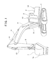
- FIG.1 shows a case where the present invention is applied on an excavator which is a construction machine.
- a machine body 2 is provided on a running driving body 1, and the machine body 2 is designed to be rotatable around a vertical center line with respect to the running driving body 1.
- the machine body 2 has an operation room 3, the operation room 3 is offset from the rotation center of the machine body 2, and a boom 4 is provided in the rotation center of the machine body 2 so that the boom 4 can be moved up and down.
- the center of the moving up and down operation (rotation center) of the boom 4 is placed on the vertical center line, and the boom 4 can be rotated around a horizontal center line, which perpendicularly crosses the vertical center line.
- an arm 5 is rotatably provided around a shaft 6, and a bucket 7, serving as a working tool, is provided at a forward end of the arm 5 so that the bucket can be freely rotated around a shaft (not shown).
- the boom 4, the arm 5, and the bucket 7 rotate on the same plane (hereinafter referred to as "rotation plane"). It is configured so that the boom 4 is moved up and down by a boom cylinder 9, the arm 5 is rotated by an arm cylinder 11, and the bucket 7 is rotated by a bucket cylinder 12. Therefore, by a cooperative operation of the rotation of the boom 4 with respect to the machine body 2, the rotation of the arm 5 with respect to the boom 4, and the rotation of the bucket 7 with respect to the arm 5, the bucket 7 can be operated in various movements such as front-to-rear movement, up-down movement, and scooping-up, and the movement of the bucket 7 is performed on the rotation plane. Further, a lower end surface 7a of the bucket 7 is designed as a flat surface, and by pressing the lower end surface 7a to the working surface or by sliding the lower end surface 7a under the pressed condition, leveling operation is carried out.
- the boom 4 and the arm 5 are connected together in a bendable manner, and constitute a working arm.
- the working arm supports the bucket 7 so that the bucket 7 can carry out a movement as required.
- the working arm is so designed that the two links of boom 4 and the arm 5, are connected together in a bendable manner, while the working arm may be designed further with three bendable links. Further, as described later, each link is arranged to have a length already known.
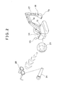
- a position acquiring means for acquiring absolute coordinates of the machine body 2 and also, as a direction detecting means for detecting direction of the machine body 2 there are provided two GPS devices, i.e. a first GPS device 13 and a second GPS device 14 at predetermined positions, preferably along a straight line passing through the rotation center of the machine body 2. It is to be noted that three or more GPS devices may be provided.
- the first GPS device 13 and the second GPS device 14 the absolute coordinates of the machine body 2 and the direction (azimuth) of the machine body 2, i.e. the direction of the bucket 7, is measured.
- a two-axis tilt sensor 15 for detecting tilting in each of the two horizontal directions are disposed. Also, there are provided a boom tilt sensor 16 (see FIG.3 ) on the boom 4, an arm tilt sensor 17 (see FIG.3 ) on the arm 5, and a bucket tilt sensor 18 (see FIG.3 ) on the bucket 7 respectively. Further, although not shown in the figure, a rotation angle detector for detecting a rotation angle of the machine body 2 is disposed. It is to be noted that each of the boom tilt sensor 16, the arm tilt sensor 17, and the bucket tilt sensor 18 may be a rotation angle detector for detecting the rotation angle. Further, the boom tilt sensor 16 and the arm tilt sensor 17 make up together a working arm tilt sensor.
- the first GPS device 13 and the second GPS device 14 are disclosed at a known position respectively with respect to a machine center of the machine body 2, and position of the operation room 3 is also known.
- a rotation center of the boom 4 is used, for instance.
- each of the length of the boom 4, the length of the arm 5, and the length from the rotation center of the bucket 7 to the forward end, and a distance from the rotation center of the bucket 7 to the center position of the bucket 7 are already known respectively.
- the bucket 7 By cooperative operation of extension and contraction of the boom cylinder 9, extension and contraction of the arm cylinder 11, and extension and contraction of the bucket cylinder 12, the bucket 7 can be moved in up-down direction, front-to-rear direction, and further rotated, and excavation work as desired can be carried out.
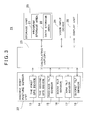
- the control device 21 comprises a machine body attitude sensor unit 22, an arithmetic unit 23, a voice input unit 24, a storage unit 25, and a display unit 26.
- the machine body attitude sensor unit 22 comprises the first GPS device 13, the second GPS device 14, the two-axis tilt sensor 15, the boom tilt sensor 16, the arm tilt sensor 17, and the bucket tilt sensor 18.
- the storage unit 25 has a program storage area 27 and a data storage area 28.
- Various types of programs are stored in the program storage area 27 such as a sequence program for controlling acquisition of signals from the machine body attitude sensor unit 22 and for controlling the displaying of images to the display unit 26, an image processing program, an image display program for displaying images on the display unit 26, and a voice input program for converting the voice inputted from the voice input unit 24 such as a microphone to a driving command to the boom cylinder 9, the arm cylinder 11, and the bucket cylinder 12.
- data such as working data necessary for civil engineering operation are stored.
- the working data comprise absolute coordinates of the working position for performing excavation work, design gradient and design height, etc. to indicate gradient and height of the lower end surface 7a of the bucket 7 when performing the excavation work.
- the display unit 26 in the present embodiment is a pair of 3D eyeglasses, for instance.
- operator wears the 3D eyeglasses.
- a guidance screen is shown, where the guiding information (to be described later) is displayed, on the 3D eyeglasses.
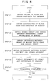
- Step 01 When the processing is started, the arithmetic unit 23 acquires the absolute coordinates of the machine body 2 from the first GPS device 13 and the second GPS device 14. Also, the arithmetic unit 23 acquires the tilting of the machine body 2, the tilting of the boom 4, the tilting of the arm 5, and the tilting of the bucket 7 from the two-axis tilt sensor 15, the boom tilt sensor 16, the arm tilt sensor 17 and the bucket tilt sensor 18.
- Step 02 the arithmetic unit 23 calculates the absolute coordinates of the blade edge of the bucket 7 and the gradient of the lower end surface 7a (hereinafter, simply referred as "gradient") of the bucket 7 based on the absolute coordinates of the machine body 2, the tilting of the machine body 2, the tilting of the boom 4, the tilting of the arm 5, and the tilting of the bucket 7, as acquired. Also, the arithmetic unit 23 calculates the direction of the bucket 7 with respect to the working position based on the working data stored in the data storage area 28.
- gradient the gradient of the lower end surface 7a
- Step 03 When the arithmetic unit 23 calculates the absolute coordinates of the blade edge of the bucket 7, the calculating unit 23 calculates the design height and the design gradient immediately under the coordinates of the blade edge of the bucket 7 based on the coordinates of the blade edge of the bucket 7 and the working data.
- Step 04 The arithmetic unit 23 calculates the difference between the height of the blade edge of the bucket 7 and design height based on the height of the blade edge of the bucket 7 calculated in Step 02, and based on the design height immediately under the blade edge of the bucket 7 calculated in Step 03.
- Step 05 the arithmetic unit 23 calculates the difference between the gradient of the bucket 7 and the design gradient and the difference between the direction of the bucket 7 and the direction of the working position, based on the gradient and direction of the bucket 7 calculated in Step 02 and based on the design gradient (the design gradient of the working position) immediately under the blade edge of the bucket 7 calculated in Step 03.
- Step 06 The arithmetic unit 23 prepares a guidance screen 31 to guide the bucket 7 to the working position as shown in FIG.5 to FIG.7 , for instance, and displays on the display unit 26, based on the difference between the height of the blade edge of the bucket 7 calculated in Step 04 and design height, and also, based on the difference between the gradient of the bucket 7 calculated in Step 05 and design gradient, and based on the difference between the direction of the bucket 7 and direction of the working position.
- Step 01 to Step 06 the procedure in Step 01 to Step 06 as described above is successively carried out during the excavation operation, and the present status of the machine body 2 and the bucket 7 - that is, the direction of the bucket 7, and the height and the gradient of the bucket 7 - are displayed on the display unit 26 in real time.
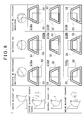
- FIG.5 to FIG.7 shows the guidance screens 31 according to the first embodiment of the present invention.
- the guidance screens 31 one of the guidance screens 31Aa to 31Ai, 31Ba to 31Bi, and 31Ca to 31Ci is to be displayed, for instance.
- a working position mark 32 which indicate a working position, which is a target position of the bucket 7, is displayed by a broken-line square at the center of each of the guidance screens 31.
- a bucket mark 33 to indicate the condition of the bucket 7 is displayed on each of the guidance screens 31 by a dual-line quadrangle. Length of the upper edge of the bucket mark 33 is always constant, and the length of the lower edge, i.e. a distance between two points adjacent to each other is variable, and the standard form of the bucket mark 33 is a square.
- FIG.5 shows the guidance screens 31Aa to 31Ai
- the guidance screens 31Aa to 31Ai are display examples of the guidance screen 31 when the gradient of the bucket 7 and the design gradient in the working data is coincident.
- the bucket mark 33 is shown as a square of standard shape. It is to be noted that the size of the square is varied so that the working position mark 32 and the bucket mark 33 do not overlap.
- the bucket mark 33 is displayed at the upper side compared with the working position mark 32, as shown in the guidance screens 31Aa to 31Ac.
- the bucket mark 33 is shown at the equal position in up-down direction as the working position mark 32, as shown in the guidance screens 31Ad to 31Af.
- the bucket mark 33 is shown at the lower side than the working position mark 32, as shown in the guidance screens 31Ag to 31Ai.
- the bucket mark 33 is displayed on the left side of the working position mark 32, as shown in the guidance screens 31Aa, 31Ad, and 31Ag.
- the bucket mark 33 is displayed so that the position in left-to-right direction is equal to the position of the working position mark 32, as shown in the guidance screens 31Ab, 31Ae, and 31Ah.
- the bucket mark 33 is displayed on the right side of the working position mark 32, as shown in the guidance screens 31Ac, 31Af, and 31Ai.
- the bucket mark 33 With respect to the position in left-to-right direction of the bucket mark 33 as shown in the guidance screen 31, it is designed so that a direction, where the amount of rotation necessary in order to make the bucket 7 face directly to the working position is smaller, is selected. That is, if the amount of rotation when the machine body 2 is rotated in rightward direction is smaller than the amount of rotation when the machine body 2 is rotated in leftward direction, the bucket mark 33 is displayed on the left side compared with the working position mark 32. Also, if the amount of rotation when the machine body 2 is rotated in leftward direction, is smaller than the amount of rotation when the machine body 2 is rotated in rightward direction, the bucket mark 33 is displayed on the right side compared with the working position mark 32.
- FIG.6 shows the guidance screens 31Ba to 31Bi
- the guidance screens 31Ba to 31Bi are display examples of the guidance screen 31 when the design gradient in the working data is larger than the gradient of the bucket 7.
- the standard shape of the bucket mark 33 is shown as the shape of isosceles trapezoid, which has its lower edge longer than the upper edge, etc.
- the bucket mark 33 is shown at an upper position compared with the working position mark 32, as shown in the guidance screens 31Ba to 31Bc.
- the bucket mark 33 is shown at a position where the position in up-down direction is equal to that of the working position mark 32, as shown in the guidance screens 31Bd to 31Bf.
- the bucket mark 33 is shown at a lower position compared with the working position mark 32, as shown in the guidance screens 31Bg to 31Bi.
- the bucket mark 33 is shown on the left side compared with the working position mark 32, as shown in the guidance screens 31Ba, 31Bd and 31Bg.
- the bucket mark 33 is displayed in a condition such that the bucket mark 33 coincide with the working position mark 32 in left-to-right position, as shown in the guidance screens 31Bb, 31Be and 31Bh.
- the bucket mark 33 is displayed on the right side compared with the working position mark 32, as shown in the guidance screens 31Bc, 31Bf and 31Bi.
- FIG.7 shows the guidance screens 31Ca to 31Ci
- the guidance screen 31Ca to 31Ci are display examples of the guidance screen 31 when the gradient of the bucket 7 is higher than the design gradient in the working data.
- the standard shape of the bucket mark 33 is given as the shape of an inverted isosceles trapezoid, which has the length of the lower edge shorter than the upper edge.
- the bucket mark 33 is displayed at an upper position compared with the working position mark 32, as shown in the guidance screens 31Ca to 31Cc.
- the bucket mark 33 is displayed in a condition where the position of the bucket mark 33 in up-down direction coincide with the working position mark 32, as shown in the guidance screens 31Cd to 31Cf.
- the bucket mark 33 is displayed at a position lower than the working position mark 32, as shown in the guidance screens 31Cg to 31Ci.
- the bucket mark 33 is displayed on the left side compared with the working position mark 32, as shown in the guidance screens 31Ca, 31Cd, and 31Cg.
- the bucket mark 33 is displayed in a condition where the bucket mark 33 with its position in left-to-right direction coincide with the working position mark 32 as shown in the guidance screens 31Cb, 31Ce and 31Ch.
- the bucket mark 33 is displayed on the right side compared with the working position mark 32, as shown in the guidance screens 31Cc, 31Cf, and 31Ci.
- Step 07 An operator rotates the machine body 2 and moves the bucket 7 based on the position of the bucket mark 33 in up-down direction, on the position in left-to-right direction, and on the shape as shown in the guidance screens 31.
- the bucket 7 is moved up so that the length of the lower edge of the bucket mark 33 coincide with the length of the upper edge.
- the machine body 2 is rotated in rightward direction so that the position of the bucket mark 33 in left-to-right direction coincide with the working position mark 32.
- the bucket 7 is moved down so that the position of the bucket mark 33 in up-down direction coincide with the working position mark 32.
- Excavating operation is carried out under the condition where the bucket mark 33 coincide with the working position mark 32. By finishing the excavating operation, the series of processes are completed.
- three types of information such as the direction of the bucket, the gradient of the bucket 7, and the height of the bucket 7 with respect to the working position, as shown in individual screens, in the Japanese Patent Publication JP-A-2012-255286 , can be displayed on a single screen according to the change of shape of the bucket mark 33 shown by a quadrangle and according to the difference of position with respect to the working position mark 32.
- 3D eyeglasses are used as the display unit 26 in the first embodiment, so the operator can carry out the excavating operation while watching the bucket 7 and the guidance screen 31 at the same time, and this is contributes to the improvement of the working efficiency.
- either one of the guidance screens 31Aa to 31Ai, 31Ba to 31Bi, and 31Ca to 31Ci is displayed, while it may be so arranged that the direction of the bucket 7 with respect to the design position, and the condition of the bucket 7 with respect to the design gradient, etc. may be displayed at the same time as shown in FIG.5 to FIG.7 .
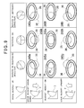
- a guidance screen 34 according to a second embodiment of the present invention.
- the guidance screens 34 it is so designed that either one of the guidance screens 34Aa to 34Ai, 34Ba to 34Bi, and 34Ca to 34Ci to be described below is displayed, for instance.
- a working position mark 35 to indicate the working position which is a target position of the bucket 7 is shown by a broken-line circle at the center of the guidance screen 34 as the guiding information.
- a bucket mark 36 to show the condition of the bucket 7 is displayed by a dual-line circle, and the standard shape of the bucket mark 36 is a shape which coincide with the working position mark 35, i.e. a circle.
- the bucket mark 36 and the working position mark 35 are designed with different diameters respectively so that the bucket mark 36 and the working position mark 35 do not overlap.
- the length of the diameter of the bucket mark 36 in up-down direction is always constant, and the length of the diameter in left-to-right direction is variable.
- FIG.8 shows the guidance screens 34Aa to 34Ai
- the guidance screens 34Aa to 34Ai are display examples of the guidance screen 34 when the gradient of the bucket 7 coincide with the design gradient in the working data.
- the bucket mark 36 is given as a circle of standard shape.
- the bucket mark 36 is displayed on an upper position compared with the working position mark 35, as shown in the guidance screens 34Aa to 34Ac.
- the bucket mark 36 is displayed in a condition such that the bucket mark 36 coincide with the working position mark 35 in up-down direction, as shown in the guidance screens 34Ad to 34Af.
- the bucket mark 36 is displayed at a lower side compared with the working position mark 35, as shown in the guidance screens 34Ag to 34Ai.
- the bucket mark 36 is displayed on the left side compared with the working position mark 35, as shown in the guidance screens 34Aa, 34Ad and 34Ag.
- the bucket mark 36 is displayed in a condition such that the bucket mark 36 coincide with the working position mark 35 in left-to-right direction, as shown in the guidance screens 34Ab, 34Ae and 34Ah.
- the bucket mark 36 is displayed on the right side compared with the working position mark 35, as shown in the guidance screens 34Ac, 34Af and 34Ai.
- FIG.9 shows the guidance screens 34Ba to 34Bi
- the guidance screens 34Ba to 34Bi are display examples of the guidance screens 34 when the design gradient in the working data is larger than the gradient of the bucket 7.
- the standard shape of the bucket mark 36 is given in a form of an ellipse, which has its diameter in left-to-right direction longer than the diameter in up-down direction.
- the bucket mark 36 is displayed on an upper side compared with the working position mark 35, as shown in the guidance screens 34Ba to 34Bc.
- the bucket mark 36 is displayed in such a manner that the bucket mark 36 coincide with the working position mark 35 in up-down direction, as shown in the guidance screens 34Bd to 34Bf.
- the bucket mark 36 is displayed at a position lower than the working position mark 35, as shown in the guidance screens 34Bg to 34Bi.
- the bucket mark 36 is displayed on the left side compared with the working position mark 35, as shown in the guidance screens 34Ba, 34Bd and 34Bg.
- the bucket mark 36 is displayed under such condition that the bucket mark 36 coincide with working position mark 35 left-to-right direction as shown in the guidance screens 34Bb, 34Be and 34Bh.
- the bucket mark 36 is displayed on the right side compared with the working position mark 35, as shown in the guidance screens 34Bc, 34Bf, and 34Bi.
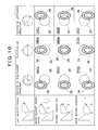
- FIG.10 shows the guidance screens 34Ca to 34Ci
- the guidance screens 34Ca to 34Ci are display examples of the guidance screens 34 when the gradient of the bucket 7 is larger than the design gradient in the working data.
- the standard shape of the bucket mark 36 is shown in form of an ellipse, which has a diameter in left-to-right direction shorter than the diameter in up-down direction.
- the bucket mark 36 is displayed at an upper side compared with the working position mark 35, as shown in the guidance screens 34Ca to 34Cc.
- the bucket mark 36 is displayed in a condition such that the bucket mark 36 coincide with the working position mark 35 in up-down direction, as shown in the guidance screens 34Cd to 34Cf.
- the bucket mark 36 is displayed at a lower side than the working position mark 35, as shown in the guidance screens 34Cg to 34Ci.
- the bucket mark 36 is displayed at a left side compared with the working position mark 35, as shown in the guidance screens 34Ca, 34Cd, and 34Cg.
- the bucket mark 36 is displayed in such a condition that the position of the bucket mark 36 coincide with the working position mark 35 in left-to-right direction, as shown in the guidance screens 34Cb, 34Ce and 34Ch.
- the bucket mark 36 is displayed at the right side compared with the working position mark 35, as shown in the guidance screens 34Cc, 34Cf and 34Ci.
- the second embodiment it is set in such a manner that the length of the diameter in up-down direction is constant while the length of the diameter in left-to-right direction is variable, while it is needless to say that the length of the diameter in left-to-right direction can be set as constant, and the length of diameter in up-down direction can be set as variable.
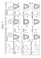
- guidance screens 37 As the guidance screens 37, either one of the guidance screens 37Aa to 37Ai, 37Ba to 37Bi, or 37Ca to 37Ci to be described later is displayed, for instance.
- a working position mark 38 to indicate the working position which is a target position of the bucket 7 is displayed by an isosceles triangle of broken line at the center of the guidance screens 37 as the guiding information.
- a bucket mark 39 to indicate the condition of the bucket 7 is shown by an isosceles triangle of dual-line, and the standard form of the bucket mark 39 is set to an isosceles triangle of the same form.
- the bucket mark 39 is always constant in height, and the length of base is variable, i.e. the distance between two points adjacent to each other is variable.
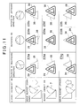
- FIG.11 shows the guidance screens 37Aa to 37Ai
- the guidance screens 37Aa to 37Ai are display examples of the guidance screens 37 in a case where the gradient of the bucket 7 coincide with the design gradient in the working data.
- the bucket mark 39 to be displayed is given as an isosceles triangle of standard form.
- the bucket mark 39 is displayed at an upper side compared with the working position mark 38, as shown in the guidance screens 37Aa to 37Ac.
- the bucket mark 39 is displayed in a condition where the working position mark 38 coincide in up-down direction, as shown in the guidance screens 37Ad to 37Af.
- the bucket mark 39 is displayed at a lower side compared with the working position mark 38, as shown in the guidance screens 37Ag to 37Ai.
- the bucket mark 39 is displayed on the left side compared with the working position mark 38, as shown in the guidance screens 37Aa, 37Ad, and 37Ag.
- the bucket mark 39 is displayed under the condition that the working position mark 38 coincide with the bucket mark 39 in left-to-right direction, as shown in the guidance screens 37Ab, 37Ae and 37Ah.
- the bucket mark 39 is displayed at the right side compared with the working position mark 38, as shown in the guidance screens 37Ac, 37Af and 37Ai.
- FIG.12 shows the guidance screens 37Ba to 37Bi
- the guidance screens 37Ba to 37Bi are display examples of the guidance screens 37 when the design gradient in the working data is larger than the gradient of the bucket 7.
- the standard shape of the bucket mark 39 displayed by an isosceles triangle which has the length of the base longer than that of the working position mark 38.
- the bucket mark 39 is displayed at the upper side compared with the working position mark 38, as shown in the guidance screens 37Ba to 37Bc.
- the bucket mark 39 is displayed in a condition where the bucket mark 39 coincide with the working position mark 38 in up-down direction, as shown in the guidance screens 37Bd to 37Bf.
- the bucket mark 39 is displayed at the lower side compared with the working position mark 38, as shown in the guidance screens 37Bg to 37Bi.
- the bucket mark 39 is displayed at a position in the leftward direction compared with the working position mark, as shown in the guidance screens 37Ba, 37Bd and 37Bg.
- the bucket mark 39 is displayed in a condition where the bucket mark 39 coincide with the working position mark 38 in left-to-right direction, as shown in the guidance screens 37Bb, 37Be and 37Bh.
- the bucket mark 39 is displayed at the right side compared with the working position mark 38, as shown in the guidance screens 37Bc, 37Bf and 37Bi.
- FIG.13 shows the guidance screens 37Ca to 37Ci
- the guidance screens 37Ca to 37Ci are display examples of the guidance screen 37 in a case where the gradient of the bucket 7 is larger than the design gradient in the working data.
- the standard shape of the bucket mark 39 is given as an isosceles triangle, where the length of the base is shorter than that of the working position mark 38.
- the bucket mark 39 is displayed at the upper side compared with the working position mark 38, as shown in the guidance screens 37Ca to 37Cc.
- the bucket mark 39 is displayed in such a condition that the bucket mark 39 coincide with the working position mark 38 in up-down direction, as shown in the guidance screens 37Cd to 37Cf.
- the bucket mark 39 is displayed at the lower side compared with the working position mark 38, as shown in the guidance screens 37Cg to 37Ci.
- the bucket mark 39 is displayed at the left side compared with the working position mark 38, as shown in the guidance screens 37Ca, 37Cd and 37Cg.
- the bucket mark 39 is displayed in such a condition that the bucket mark 39 coincide with the working position mark 38 in left-to-right direction, as shown in the guidance screens 37Cb, 37Ce and 37Ch.
- the bucket mark 39 is displayed at a position on the right side compared with the working position mark 38, as shown in the guidance screens 37Cc, 37Cf and 37Ci.
- guidance screens 41 in a fourth embodiment of the present invention.
- the guidance screens 41 either one of the guidance screens 41Aa to 41Ai, 41Ba to 41Bi, and 41Ca to 41Ci to be described later is displayed, for instance.
- a working position mark 42 to indicate the working position which is a target position of the bucket 7 as guiding information, is displayed as a trapezoid of broken-line at the center of the guidance screens 41.
- a bucket mark 43 to indicate the condition of the bucket 7 is displayed in form of an isosceles trapezoid of dual line, and a standard form of the bucket mark 43 is given as an isosceles trapezoid of the same form as that of the working position mark 42.
- the bucket mark 43 has the length of its upper edge always constant, while the length of the lower edge is variable, i.e. a distance between two points adjacent to each other of the lower edge is variable.
- FIG.14 shows the guidance screens 41Aa to 41Ai, and the guidance screens 41Aa to 41Ai are display examples of the guidance screens 41 when the gradient of the bucket 7 coincide with the design gradient in the working data.
- the bucket mark 43 to be displayed is given as an isosceles trapezoid of standard form.
- the bucket mark 43 is displayed at the upper side compared with the working position mark 42, as shown in the guidance screens 41Aa to 41Ac.
- the bucket mark 43 is displayed in such a condition where the bucket mark 43 coincide with the working position mark 42 in up-down direction, as shown in the guidance screens 41Ad to 41Af.
- the bucket mark 43 is displayed at the lower side compared with the working position mark 42, as shown in the guidance screens 41Ag to 41Ai.
- the bucket mark 43 is displayed at a position on the left side compared with the working position mark 42, as shown in the guidance screens 41Aa, 41Ad and 41Ag.
- the bucket mark 43 is displayed in such a condition that the position of the bucket mark 43 coincides with the working position mark 42 in left-to-right direction, as shown in the guidance screens 41Ab, 41Ae and 41Ah.
- the bucket mark 43 is displayed at a position on the right side compared with the position of the working position mark 42, as shown in the guidance screens 4lAc, 41Af and 41Ai.
- FIG. 15 shows the guidance screens 41Ba to 41Bi, and the guidance screens 41Ba to 41Bi are display examples of the guidance screens 41 in a case where the design gradient in the working data is larger than the gradient of the bucket 7.
- the standard form of the bucket mark 43 is given by a form of an isosceles trapezoid, where the length of the lower edge is longer than that of the working position mark 42.
- the bucket mark 43 is displayed at the upper side compared with the working position mark 42, as shown in the guidance screens 41Ba to 41Bc.
- the bucket mark 43 is displayed in such a condition where the position of the bucket mark 43 coincide with the working position mark 42 in up-down direction, as shown in the guidance screens 41Bd to 41Bf.
- the bucket mark 43 is displayed at the lower side compared with the working position mark 42, as shown in the guidance screens 41Bg to 41Bi.
- the bucket mark 43 is displayed at the left side compared with the working position mark 42, as shown in the guidance screens 41Ba, 41Bd and 41Bg.
- the bucket mark 43 is displayed with the position of the bucket mark 43 to coincide with the working position mark 42 in left-to-right direction, as shown in the guidance screens 41Bb, 41Be and 41Bh.
- the bucket mark 43 is displayed at the right side compared with the position of the working position mark 42, as shown in the guidance screens 41Bc, 41Bf and 41Bi.
- FIG.16 shows the guidance screens 41Ca to 41Ci
- the guidance screens 41Ca to 41Ci are display examples of the guidance screens 41 when the gradient of the bucket 7 is larger than the design gradient in the working data.
- the standard form of the bucket mark 43 is given by a form of a trapezoid, where the length of the lower edge is shorter than the working position mark 42.
- the bucket mark 43 is displayed at the upper side compared with the working position mark 42, as shown in the guidance screens 41Ca to 41Cc.
- the bucket mark 43 is displayed in the condition where the position of the bucket mark 43 coincide with the working position mark 42 in up-down direction, as shown in the guidance screens 41Cd to 41Cf.
- the bucket mark 43 is displayed at the lower side compared with the working position mark 42, as shown in the guidance screens 41Cg to 41Ci.
- the bucket mark 43 is displayed at a position on the left side compared with the working position mark 42, as shown in the guidance screens 41Ca, 41Cd and 41Cg.
- the bucket mark 43 is displayed in such a condition that the bucket mark 43 coincide with the working position mark 42 in left-to-right direction, as shown in the guidance screens 41Cb, 41Ce and 41Ch.
- the bucket mark 43 is displayed at the right side compared with the position of the working position mark 42, as shown in the guidance screens 41Cc, 41Cf and 41Ci.
- three types of information such as the direction of the bucket 7, the gradient of the bucket 7, and the height of the bucket 7 with respect to the working position, as shown in individual screens, in the Japanese Patent Publication JP-A-2012-255286 , can be displayed on a single screen according to the change of shape of the bucket marks 36, 39, and 43 shown by a predetermined shape such as a circle, a triangle, a trapezoid, etc., and according to the difference of position with respect to the working position marks 35, 38, and 42. Therefore, the operator can easily identify the guiding information up to the target position, and this contributes to the improvement of working efficiency in the excavation operation.
- 3D eyeglasses are used as the display unit 26, and it is so designed that excavation operation is carried out while watching the bucket 7 and the guidance screens 31, 34, 37 and 41 at the same time, while it may also be so designed that a display unit such as monitor may be provided separately in the operation room 3, and the guidance screens 31, 34, 37 and 41 may be displayed on the display unit.
- each of the working position marks 32, 35, 38, and 42 and the bucket marks 33, 36, 39 and 43 is expressed in shape of a quadrangle, a circle, a triangle and a trapezoid, while it is needless to say that if the direction of the machine body 2 and the gradient and the height of the bucket 7 can be expressed by means of form and position, other shapes, such as a polygonal or an ellipse other than a triangle, or a quadrangle.
- the length of one edge is variable, i.e. a distance between two points adjacent to each other is variable, while it may be arranged in such a manner that the bucket mark may be designed as a pentagon or a hexagon, for instance, and by setting the distance between two points not adjacent to each other as variable, the form of the bucket mark may be changed.
- the bucket marks 33, 36, 39 and 43 are displayed in dual lines, while it may be arranged in such a manner that the bucket marks 33, 36, 39 and 43 may be displayed in different colors, or the like, compared with the working position marks 32, 35, 38 and 42, and when the working position marks 32, 35, 38 and 42 overlaps the bucket marks 33, 36, 39 and 43, other formalities may be used for display as far as two groups can be discriminated from each other.
- the direction of the machine body 2 and the gradient and the height of the bucket 7 are expressed only according to the shape of the bucket marks 33, 36, 39 and 43 and according to the positions with respect to the working position marks 32, 35, 38 and 42, while combination of other data such as characters, arrow-marks, etc. may be displayed as described below.
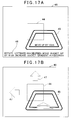
- FIG.17A to FIG.17E show other display examples of guidance screens 46, showing a case where the working position mark 44 and the bucket marks 45 are combined with other data.
- FIG.17A shows a case where the guiding information up to the target position is expressed according to the combination of the working position mark 44 and the bucket mark 45, and further numerical value information such as a distance to the target position is expressed by characters 48.
- the guiding is performed by using not only the working position mark 44 and the bucket mark 45, but also by the characters 48. As a result, the guiding information up to the target position can be identified in easier manner.
- FIG.17B shows a case where the guiding information up to the target position is expressed according to the combination of the working position mark 44 and the bucket mark 45, and an arrowmark 47 to indicate the direction to the target position.
- the guiding is performed by using not only the working position mark 44 and the bucket mark 45, but also by the arrowmark 47.
- the guiding information up to the target position can be identified in easier manner. It is to be noted that it may be arranged in such a manner that the arrowmarks 47 are given in larger size when the distance to the target position is far, or the arrowmarks 47 are given in smaller size when the distance to the target position is close, so that the distance to the target position can be identified by the change of the shape of the arrowmark 47.
- FIG.17C shows a case where not only the working position mark 44 and the bucket mark 45 but also the GPS condition, which shows the number of satellites receiving, are displayed on the guidance screen 46.
- FIG.17D shows a combination of the guidance screen 46 shown in FIG.17B and the guidance screen 46 shown in FIG.17C .
- the arrowmarks 47 are displayed as the guiding information in addition to the working position mark 44 and the bucket mark 45, and the working data and the GPS condition are displayed on the guidance screens 46 at the same time as the working position mark 44, the bucket mark 45, and the arrowmarks 47.
- the guiding information up to the target position can be identified in an easier manner, and it is possible to identify the guiding information and the present condition at the same time, and can identify the accuracy of the guiding information.
- two GPS devices i.e. the first GPS device 13 and the second GPS device 14 (see FIG.1 ) are used as a position acquiring means for acquiring the absolute coordinates of the machine body 2, but only one GPS device may be used in a case where excavation operation is carried out when the machine body 2 is operated without moving, at a predetermined position.
- the machine body 2 is rotated while GPS measurement is performed by the GPS device.
- the arithmetic unit 23 calculates the absolute coordinates of the rotation center with respect to a horizontal plane, calculates the absolute coordinate of the machine center of the machine body 2 based on the calculation result, and acquires the absolute coordinates of the machine center of the machine body 2.
- the arithmetic unit 23 calculates the rotating direction (azimuth) of the machine body 2, i.e. the direction of the bucket 7, and the direction of the bucket 7 can be acquired.
- a rotating direction acquiring device for acquiring the rotating direction of the machine body 2 is configured.
- the GPS device in a case where the GPS device is provided at an unknown position with respect to the machine center of the machine body 2, it may be designed in such a manner that the formula of a locus of a circle thus formed can be acquired by the GPS device when the arithmetic unit 23 rotates the machine body 2, and the rotating center of the machine body 2 may be obtained from the formula thus acquired.
- the arithmetic unit 23 specifies the position of the GPS device on the locus of the circle, and the rotating direction of the machine body 2 can be acquired from the coordinates of the rotating center of the machine body 2 and position of the GPS device.
- one total station installed at a known position with respect to the machine center of the machine body 2 may be used.
- a prism is provided at a predetermined point on the machine body 2, and tracking is carried out on the prism by the total station. From the total station, a distance and a rotation angle to the prism is obtained respectively, and based on the distance and the rotation angle as obtained, the arithmetic unit 23 calculates the absolute coordinates of the machine body 2, and the absolute coordinates of the machine body 2 can be acquired.
- the total station and the prism make up together a position acquiring means for acquiring absolute coordinates of the machine body 2.
Landscapes
- Engineering & Computer Science (AREA)
- Mining & Mineral Resources (AREA)
- Civil Engineering (AREA)
- General Engineering & Computer Science (AREA)
- Structural Engineering (AREA)
- Mechanical Engineering (AREA)
- Physics & Mathematics (AREA)
- General Physics & Mathematics (AREA)
- Radar, Positioning & Navigation (AREA)
- Remote Sensing (AREA)
- Component Parts Of Construction Machinery (AREA)
- Operation Control Of Excavators (AREA)
Applications Claiming Priority (1)
| Application Number | Priority Date | Filing Date | Title |
|---|---|---|---|
| JP2013051315A JP6147037B2 (ja) | 2013-03-14 | 2013-03-14 | 建設機械制御システム |
Publications (2)
| Publication Number | Publication Date |
|---|---|
| EP2778293A2 true EP2778293A2 (de) | 2014-09-17 |
| EP2778293A3 EP2778293A3 (de) | 2014-12-24 |
Family
ID=50272430
Family Applications (1)
| Application Number | Title | Priority Date | Filing Date |
|---|---|---|---|
| EP20140159285 Withdrawn EP2778293A3 (de) | 2013-03-14 | 2014-03-12 | Steuerungssystem für Baumaschine |
Country Status (3)
| Country | Link |
|---|---|
| US (1) | US9540786B2 (de) |
| EP (1) | EP2778293A3 (de) |
| JP (1) | JP6147037B2 (de) |
Cited By (5)
| Publication number | Priority date | Publication date | Assignee | Title |
|---|---|---|---|---|
| EP3236203A1 (de) * | 2016-04-21 | 2017-10-25 | MOBA - Mobile Automation AG | Verfahren und totalstation zur steuerung einer baumaschine |
| KR20180054638A (ko) * | 2015-09-15 | 2018-05-24 | 스미토모 겐키 가부시키가이샤 | 쇼벨 |
| CN108884669A (zh) * | 2016-03-31 | 2018-11-23 | 住友建机株式会社 | 挖土机 |
| CN110331756A (zh) * | 2019-06-11 | 2019-10-15 | 潍柴动力股份有限公司 | 挖掘机的辅助控制装置、控制系统和控制方法 |
| CN112681413A (zh) * | 2020-12-21 | 2021-04-20 | 徐州威卡电子控制技术有限公司 | 一种半自动控制挖机三联动修坡系统及方法 |
Families Citing this family (19)
| Publication number | Priority date | Publication date | Assignee | Title |
|---|---|---|---|---|
| JP6883813B2 (ja) | 2014-10-27 | 2021-06-09 | ヤンマーパワーテクノロジー株式会社 | トラクタ |
| WO2016067986A1 (ja) * | 2014-10-27 | 2016-05-06 | ヤンマー株式会社 | 作業車両 |
| JP6392097B2 (ja) * | 2014-11-27 | 2018-09-19 | 住友建機株式会社 | ショベルの支援装置及びショベルの支援方法 |
| JP6777375B2 (ja) * | 2015-03-05 | 2020-10-28 | 株式会社小松製作所 | 作業機械の画像表示システム、作業機械の遠隔操作システム及び作業機械 |
| KR20180042251A (ko) | 2015-08-26 | 2018-04-25 | 스미토모 겐키 가부시키가이샤 | 쇼벨의 계측장치 |
| WO2017170555A1 (ja) * | 2016-03-31 | 2017-10-05 | 住友重機械工業株式会社 | ショベル |
| US10589626B2 (en) | 2016-06-20 | 2020-03-17 | Caterpillar Inc. | Implement positioning guidance system |
| USD800764S1 (en) | 2016-06-20 | 2017-10-24 | Caterpillar Inc. | Display screen or portion thereof with set of icons |
| US12241226B2 (en) * | 2016-08-31 | 2025-03-04 | Komatsu Ltd. | Image display system of work machine, remote operation system of work machine, work machine, and method for displaying image of work machine |
| WO2018062374A1 (ja) | 2016-09-30 | 2018-04-05 | 住友建機株式会社 | ショベル |
| EP3604695B1 (de) * | 2017-03-31 | 2021-07-28 | Sumitomo (S.H.I.) Construction Machinery Co., Ltd. | Schaufel mit anzeigevorrichtung und bildanzeigeverfahren in der schaufel |
| WO2020101006A1 (ja) * | 2018-11-14 | 2020-05-22 | 住友重機械工業株式会社 | ショベル、ショベルの制御装置 |
| CN109855611B (zh) * | 2019-03-27 | 2022-03-15 | 中南大学 | 一种基于全站仪的pc墙体快速测量校准方法 |
| JP7138072B2 (ja) * | 2019-04-18 | 2022-09-15 | 三菱マヒンドラ農機株式会社 | マルチ田植機 |
| JP6966108B2 (ja) * | 2020-03-18 | 2021-11-10 | Totalmasters株式会社 | 建設作業機械の測位較正方法及びその測位較正コントローラ |
| US12351995B2 (en) | 2022-04-28 | 2025-07-08 | Caterpillar Paving Products Inc. | Auto scratch height for work machines |
| US20230358016A1 (en) * | 2022-05-04 | 2023-11-09 | Caterpillar Inc. | Controller, operator assistance system, and method of assisting operator of work machine |
| US20230358135A1 (en) * | 2022-05-04 | 2023-11-09 | McKelley Equipment, LLC | System and Method for Ascertaining Location |
| US12473709B2 (en) * | 2023-03-09 | 2025-11-18 | Kubota Corporation | Working machine |
Citations (2)
| Publication number | Priority date | Publication date | Assignee | Title |
|---|---|---|---|---|
| JP2002181538A (ja) | 2000-12-14 | 2002-06-26 | Topcon Corp | Gpsを用いた施工端部位置検出装置 |
| JP2012255286A (ja) | 2011-06-08 | 2012-12-27 | Topcon Corp | 建設機械制御システム |
Family Cites Families (20)
| Publication number | Priority date | Publication date | Assignee | Title |
|---|---|---|---|---|
| US5438771A (en) * | 1994-05-10 | 1995-08-08 | Caterpillar Inc. | Method and apparatus for determining the location and orientation of a work machine |
| US5701400A (en) * | 1995-03-08 | 1997-12-23 | Amado; Carlos Armando | Method and apparatus for applying if-then-else rules to data sets in a relational data base and generating from the results of application of said rules a database of diagnostics linked to said data sets to aid executive analysis of financial data |
| US6233545B1 (en) * | 1997-05-01 | 2001-05-15 | William E. Datig | Universal machine translator of arbitrary languages utilizing epistemic moments |
| KR100498853B1 (ko) * | 2000-11-17 | 2005-07-04 | 히다치 겡키 가부시키 가이샤 | 건설기계의 표시장치 및 표시제어장치 |
| US6782644B2 (en) | 2001-06-20 | 2004-08-31 | Hitachi Construction Machinery Co., Ltd. | Remote control system and remote setting system for construction machinery |
| JP4532789B2 (ja) * | 2001-07-25 | 2010-08-25 | 株式会社小松製作所 | 作業機械の管理装置 |
| US7099745B2 (en) * | 2003-10-24 | 2006-08-29 | Sap Aktiengesellschaft | Robot system using virtual world |
| JP2005256469A (ja) * | 2004-03-12 | 2005-09-22 | Hitachi Constr Mach Co Ltd | 施工作業領域の設定・管理システム |
| US20110258049A1 (en) * | 2005-09-14 | 2011-10-20 | Jorey Ramer | Integrated Advertising System |
| US20090138307A1 (en) * | 2007-10-09 | 2009-05-28 | Babcock & Brown Lp, A Delaware Limited Partnership | Automated financial scenario modeling and analysis tool having an intelligent graphical user interface |
| US20090177337A1 (en) * | 2008-01-07 | 2009-07-09 | Caterpillar Inc. | Tool simulation system for remotely located machine |
| JP5469899B2 (ja) * | 2009-03-31 | 2014-04-16 | 株式会社トプコン | 自動追尾方法及び測量装置 |
| JP2009150218A (ja) * | 2009-04-02 | 2009-07-09 | Toa Harbor Works Co Ltd | 浚渫における施工管理方法 |
| US8340873B2 (en) * | 2010-01-20 | 2012-12-25 | Caterpillar Trimble Control Technologies, Llc | Machine control and guidance system incorporating a portable digital media device |
| EP2527541A1 (de) * | 2010-01-22 | 2012-11-28 | Hitachi Construction Machinery Co., Ltd. | Ladungsführungssystem |
| US8296221B1 (en) * | 2010-08-04 | 2012-10-23 | Alpha Vision Services, Llc | Methods and systems related to securities trading |
| JP5054833B2 (ja) | 2011-02-22 | 2012-10-24 | 株式会社小松製作所 | 油圧ショベルの表示システム及びその制御方法 |
| US9916538B2 (en) * | 2012-09-15 | 2018-03-13 | Z Advanced Computing, Inc. | Method and system for feature detection |
| US9540879B2 (en) | 2012-01-05 | 2017-01-10 | Merlin Technology, Inc. | Directional drilling target steering apparatus and method |
| US10203762B2 (en) * | 2014-03-11 | 2019-02-12 | Magic Leap, Inc. | Methods and systems for creating virtual and augmented reality |
-
2013
- 2013-03-14 JP JP2013051315A patent/JP6147037B2/ja active Active
-
2014
- 2014-03-11 US US14/204,345 patent/US9540786B2/en active Active
- 2014-03-12 EP EP20140159285 patent/EP2778293A3/de not_active Withdrawn
Patent Citations (2)
| Publication number | Priority date | Publication date | Assignee | Title |
|---|---|---|---|---|
| JP2002181538A (ja) | 2000-12-14 | 2002-06-26 | Topcon Corp | Gpsを用いた施工端部位置検出装置 |
| JP2012255286A (ja) | 2011-06-08 | 2012-12-27 | Topcon Corp | 建設機械制御システム |
Cited By (11)
| Publication number | Priority date | Publication date | Assignee | Title |
|---|---|---|---|---|
| KR20180054638A (ko) * | 2015-09-15 | 2018-05-24 | 스미토모 겐키 가부시키가이샤 | 쇼벨 |
| EP3351692A4 (de) * | 2015-09-15 | 2018-09-05 | Sumitomo (S.H.I.) Construction Machinery Co., Ltd. | Schaufel |
| US10927528B2 (en) | 2015-09-15 | 2021-02-23 | Sumitomo(S.H.I.) Construction Machinery Co., Ltd. | Shovel |
| KR102522714B1 (ko) | 2015-09-15 | 2023-04-14 | 스미토모 겐키 가부시키가이샤 | 쇼벨 |
| CN108884669A (zh) * | 2016-03-31 | 2018-11-23 | 住友建机株式会社 | 挖土机 |
| EP3438356A4 (de) * | 2016-03-31 | 2019-04-03 | Sumitomo (S.H.I.) Construction Machinery Co., Ltd. | Schaufel |
| US10934688B2 (en) | 2016-03-31 | 2021-03-02 | Sumitomo(S.H.I.) Construction Machinery Co., Ltd. | Shovel |
| EP3236203A1 (de) * | 2016-04-21 | 2017-10-25 | MOBA - Mobile Automation AG | Verfahren und totalstation zur steuerung einer baumaschine |
| CN110331756A (zh) * | 2019-06-11 | 2019-10-15 | 潍柴动力股份有限公司 | 挖掘机的辅助控制装置、控制系统和控制方法 |
| CN112681413A (zh) * | 2020-12-21 | 2021-04-20 | 徐州威卡电子控制技术有限公司 | 一种半自动控制挖机三联动修坡系统及方法 |
| CN112681413B (zh) * | 2020-12-21 | 2022-06-03 | 徐州威卡电子控制技术有限公司 | 一种半自动控制挖机三联动修坡系统及方法 |
Also Published As
| Publication number | Publication date |
|---|---|
| US9540786B2 (en) | 2017-01-10 |
| JP6147037B2 (ja) | 2017-06-14 |
| US20140271074A1 (en) | 2014-09-18 |
| EP2778293A3 (de) | 2014-12-24 |
| JP2014177784A (ja) | 2014-09-25 |
Similar Documents
| Publication | Publication Date | Title |
|---|---|---|
| EP2778293A2 (de) | Steuerungssystem für Baumaschine | |
| JP6827123B2 (ja) | 作業機械 | |
| US10900201B2 (en) | Display system of working machine and working machine | |
| EP3550262B1 (de) | Vermessungsinstrument | |
| US9207078B2 (en) | Device for measuring and marking space points along horizontally running contour lines | |
| US20150354954A1 (en) | Surveying Instrument | |
| KR102447168B1 (ko) | 쇼벨 및 쇼벨의 제어방법 | |
| KR20210034070A (ko) | 교정 작업 지원 시스템 | |
| WO2021182294A1 (ja) | 測量方法、測量システム、およびプログラム | |
| JP2012255286A (ja) | 建設機械制御システム | |
| EP3945282B1 (de) | Vermessungssystem, absteckassistenzverfahren und absteckassistenzprogramm | |
| JP6433033B1 (ja) | 建方支援システム及び建方支援システムに用いられるモバイル機器 | |
| JP2021085767A (ja) | 基礎杭の施工支援方法及び施工支援システム | |
| JP6174199B1 (ja) | 誘導方法及び画像表示システム | |
| JP7386592B2 (ja) | 建設機械の操作補助システム | |
| JP6721224B1 (ja) | 基礎杭の施工支援装置 | |
| WO2018164078A1 (ja) | 建築作業機械における回転部材の回転中心取得方法 | |
| JP2002146846A (ja) | 建設機械の施工案内装置 | |
| JP2022173478A (ja) | 建設機械の自動制御システム | |
| JP7353126B2 (ja) | 測量システム | |
| CN216873289U (zh) | 摄像头控制装置及作业机械 | |
| JP2021089208A (ja) | 掘削支援システム | |
| JP6062664B2 (ja) | 測量装置、測量方法、及びプログラム | |
| JP2020204265A (ja) | 油圧ショベル | |
| JP6734685B2 (ja) | 測量装置の位置取得方法及び測量装置 |
Legal Events
| Date | Code | Title | Description |
|---|---|---|---|
| 17P | Request for examination filed |
Effective date: 20140312 |
|
| AK | Designated contracting states |
Kind code of ref document: A2 Designated state(s): AL AT BE BG CH CY CZ DE DK EE ES FI FR GB GR HR HU IE IS IT LI LT LU LV MC MK MT NL NO PL PT RO RS SE SI SK SM TR |
|
| AX | Request for extension of the european patent |
Extension state: BA ME |
|
| PUAI | Public reference made under article 153(3) epc to a published international application that has entered the european phase |
Free format text: ORIGINAL CODE: 0009012 |
|
| PUAL | Search report despatched |
Free format text: ORIGINAL CODE: 0009013 |
|
| AK | Designated contracting states |
Kind code of ref document: A3 Designated state(s): AL AT BE BG CH CY CZ DE DK EE ES FI FR GB GR HR HU IE IS IT LI LT LU LV MC MK MT NL NO PL PT RO RS SE SI SK SM TR |
|
| AX | Request for extension of the european patent |
Extension state: BA ME |
|
| RIC1 | Information provided on ipc code assigned before grant |
Ipc: E02F 3/43 20060101AFI20141117BHEP |
|
| R17P | Request for examination filed (corrected) |
Effective date: 20150424 |
|
| RBV | Designated contracting states (corrected) |
Designated state(s): AL AT BE BG CH CY CZ DE DK EE ES FI FR GB GR HR HU IE IS IT LI LT LU LV MC MK MT NL NO PL PT RO RS SE SI SK SM TR |
|
| STAA | Information on the status of an ep patent application or granted ep patent |
Free format text: STATUS: THE APPLICATION IS DEEMED TO BE WITHDRAWN |
|
| 18D | Application deemed to be withdrawn |
Effective date: 20171003 |