EP2777901A1 - Dispositif de fixation pour outils électro-portatifs - Google Patents
Dispositif de fixation pour outils électro-portatifs Download PDFInfo
- Publication number
- EP2777901A1 EP2777901A1 EP14172060.7A EP14172060A EP2777901A1 EP 2777901 A1 EP2777901 A1 EP 2777901A1 EP 14172060 A EP14172060 A EP 14172060A EP 2777901 A1 EP2777901 A1 EP 2777901A1
- Authority
- EP
- European Patent Office
- Prior art keywords
- cover portion
- engagement means
- nut
- bar
- engagement
- Prior art date
- Legal status (The legal status is an assumption and is not a legal conclusion. Google has not performed a legal analysis and makes no representation as to the accuracy of the status listed.)
- Granted
Links
- 238000007689 inspection Methods 0.000 description 3
- 238000004140 cleaning Methods 0.000 description 2
- 238000010276 construction Methods 0.000 description 1
- 230000007547 defect Effects 0.000 description 1
- 230000007774 longterm Effects 0.000 description 1
- 238000004519 manufacturing process Methods 0.000 description 1
- 230000002093 peripheral effect Effects 0.000 description 1
- 230000003442 weekly effect Effects 0.000 description 1
Images

Classifications
-
- B—PERFORMING OPERATIONS; TRANSPORTING
- B27—WORKING OR PRESERVING WOOD OR SIMILAR MATERIAL; NAILING OR STAPLING MACHINES IN GENERAL
- B27B—SAWS FOR WOOD OR SIMILAR MATERIAL; COMPONENTS OR ACCESSORIES THEREFOR
- B27B17/00—Chain saws; Equipment therefor
- B27B17/02—Chain saws equipped with guide bar
-
- B—PERFORMING OPERATIONS; TRANSPORTING
- B27—WORKING OR PRESERVING WOOD OR SIMILAR MATERIAL; NAILING OR STAPLING MACHINES IN GENERAL
- B27B—SAWS FOR WOOD OR SIMILAR MATERIAL; COMPONENTS OR ACCESSORIES THEREFOR
- B27B17/00—Chain saws; Equipment therefor
- B27B17/14—Arrangements for stretching the chain saw
-
- F—MECHANICAL ENGINEERING; LIGHTING; HEATING; WEAPONS; BLASTING
- F16—ENGINEERING ELEMENTS AND UNITS; GENERAL MEASURES FOR PRODUCING AND MAINTAINING EFFECTIVE FUNCTIONING OF MACHINES OR INSTALLATIONS; THERMAL INSULATION IN GENERAL
- F16B—DEVICES FOR FASTENING OR SECURING CONSTRUCTIONAL ELEMENTS OR MACHINE PARTS TOGETHER, e.g. NAILS, BOLTS, CIRCLIPS, CLAMPS, CLIPS OR WEDGES; JOINTS OR JOINTING
- F16B37/00—Nuts or like thread-engaging members
- F16B37/04—Devices for fastening nuts to surfaces, e.g. sheets, plates
- F16B37/041—Releasable devices
- F16B37/043—Releasable devices with snap action
-
- F—MECHANICAL ENGINEERING; LIGHTING; HEATING; WEAPONS; BLASTING
- F16—ENGINEERING ELEMENTS AND UNITS; GENERAL MEASURES FOR PRODUCING AND MAINTAINING EFFECTIVE FUNCTIONING OF MACHINES OR INSTALLATIONS; THERMAL INSULATION IN GENERAL
- F16B—DEVICES FOR FASTENING OR SECURING CONSTRUCTIONAL ELEMENTS OR MACHINE PARTS TOGETHER, e.g. NAILS, BOLTS, CIRCLIPS, CLAMPS, CLIPS OR WEDGES; JOINTS OR JOINTING
- F16B41/00—Measures against loss of bolts, nuts, or pins; Measures against unauthorised operation of bolts, nuts or pins
- F16B41/002—Measures against loss of bolts, nuts or pins
-
- F—MECHANICAL ENGINEERING; LIGHTING; HEATING; WEAPONS; BLASTING
- F16—ENGINEERING ELEMENTS AND UNITS; GENERAL MEASURES FOR PRODUCING AND MAINTAINING EFFECTIVE FUNCTIONING OF MACHINES OR INSTALLATIONS; THERMAL INSULATION IN GENERAL
- F16B—DEVICES FOR FASTENING OR SECURING CONSTRUCTIONAL ELEMENTS OR MACHINE PARTS TOGETHER, e.g. NAILS, BOLTS, CIRCLIPS, CLAMPS, CLIPS OR WEDGES; JOINTS OR JOINTING
- F16B5/00—Joining sheets or plates, e.g. panels, to one another or to strips or bars parallel to them
- F16B5/02—Joining sheets or plates, e.g. panels, to one another or to strips or bars parallel to them by means of fastening members using screw-thread
Definitions
- the present invention deals with attaching arrangements for hand-held motor-driven tools, such as chain saws. Especially, the invention deals with arrangements for attaching a bar of such a hand-held motor-driven tool to a body of the tool.
- a conventional chain saw includes a body and a guide bar that supports the saw chain.
- a cover clamps the guide bar to the body by means of a tightening arrangement, comprising a bar bolt and a nut.
- a tightening arrangement comprising a bar bolt and a nut.
- the cover may have to be detached from the body.
- the tightening arrangement has to be loosened such that the nut is detached from the bar bolt.
- the object is achieved by an arrangement for attaching a bar of a hand-held motor driven tool, such as a chain saw, to a body of the tool, according to claim 1 of the present invention.
- the arrangement comprises: at least one first engagement means, having a first part, securely arranged to the body, and a second part extending from the body, the second part having an engagement portion for engaging a second engagement means; a cover portion adapted to bear against a bar such that the bar is arranged between the cover portion and the body; at least one second engagement means, captively attached to the cover portion, wherein the second engagement means is adapted to engage the engagement portion of the first engagement means for securing a bar between the cover portion and the body, the second engagement means having a rotation axis.
- the second engagement means is arranged to move a first distance (A) along the engagement portion of the first engagement means, in a direction of the rotation axis of the second engagement means, for securing a bar between the cover portion and the body.
- first and second engagement means are not engaged, the second engagement means is captively attached to the cover portion in such a way that it is movable a second distance (B) relative the cover portion in a direction of the rotation axis of the second engagement means, wherein the second distance (B) is larger than the first distance (A).
- the second engagement means is captively attached to the cover portion in such a way that it is movable a second distance (B) relative the cover portion in a direction of the rotation axis of the second engagement means, wherein the second distance (B) is larger than the first distance (A).
- the second engagement means By captively attaching the second engagement means to the cover portion in such a way, it is possible for an operator to put the cover portion onto the first engagement means such that the cover portion can be pressed towards the bar for clamping the bar between the cover portion and the body of the tool before the operator starts to engage the second engagement means to the first engagement means. Thereby, mounting the cover portion to the bar is facilitated when a second engagement means captively attached to the cover portion is used.
- the solution also ensures correct mounting of the cover portion to the body, which is especially crucial if a brake is mounted in the cover portion.
- the cover portion has an inner surface that, when the cover portion is arranged to the body, is directed towards the body, and an outer surface that, when the cover portion is arranged to the body, is directed away from the body.
- the cover portion further has a through aperture extending between the inner and outer surfaces for receiving the second part of the first engagement means.
- the cover portion further comprises at least one recess in which an attaching portion of the second engagement means is arranged for captively attaching the second engagement means to the cover portion.
- the nut By arranging the cover portion with such a recess and such a through aperture, the nut can be captively attached to the cover portion and still have a certain play in the direction of the nut rotation axis, in relation to the cover portion.
- the cover portion has guiding means for guiding the first engagement means towards the second engagement means. Thereby, it is facilitated to guide the cover portion correctly onto the first attachment means, since when the first attachment means is inserted into the guiding means the first attachment means is guided towards the second attachment means, whereby a correct arrangement of the cover portion to the body is achieved.
- At least a part of the through aperture has substantially the same cross-sectional dimension as a cross-sectional dimension of the first engagement means.
- the inner walls of the through aperture functions as a guiding means for guiding the first engagement means towards the second engagement means.
- the at least one recess of the cover portion is arranged separately from the through aperture.
- the second distance B, the distance that the second engagement means is movable relative the cover portion can be increased and still it is possible to use the whole length of the through aperture as a guiding means for guiding the first engagement means towards the second engagement means.
- the second engagement means comprises a holder portion and an engagement portion, the engagement portion being rotatably attached to the holder portion. Since the engagement portion is rotatably attached to the holder portion, the holder portion can be captively attached to the cover portion without having to be rotatable. Thereby, the cover portion does not have to allow rotational movement of the holder portion in the cover portion, resulting in less free space necessary for the second engagement means in the cover portion.
- At least one attaching portion of the holder portion of the second engagement means has a resilient structure.
- the holder portion can be snap-fitted into the at least one recess of the cover portion, which results in a quick captive mounting of the second engagement means to the cover portion.
- the at least one attaching portion comprises at least three attaching portions cooperating with at least three separate recesses of the cover portion.
- the at least one recess for captively attaching the second engagement means to the cover portion is a part of the through aperture for receiving the first engagement means.
- the attaching portion of the second engagement means comprises a protrusion extending in a direction away from the rotation axis of the second engagement means
- the cover portion comprises a protrusion extending in a direction towards the rotation axis of the second engagement means, said protrusions being arranged to cooperate such that the second engagement means is captively attached to the cover portion.
- the cover portion has a base portion and a plate portion, wherein the plate portion is attached to the base portion by means of an attachment device, and wherein the protrusion of the cover portion is part of the plate portion.
- the arrangement comprises at least two first engagement means and at least two second engagement means, each of the at least two second engagement means being arranged to cooperate with a respective one of the at least two first engagement means.
- a hand-held motor-driven tool such as a chain saw
- the tool comprises a body and a bar and an arrangement according to the present invention.
- the hand-held motor-driven tool is a chain saw having a body and a chain guiding bar that in a conventional manner supports and guides a saw chain in a peripheral groove of the bar.
- the saw chain is driven by a sprocket wheel, hidden under a cover portion.
- the body is provided with an engine that via a driving arrangement drives the sprocket wheel.
- the guide bar extends forwardly in the longitudinal direction of the chain saw, and the rearward end of the bar is clamped between the body and the cover portion by means of a tightening arrangement.
- FIG. 1 A first embodiment of the present invention is shown in figs. 1-3.
- FIGs. 1 and 2 show a portion of a chain saw including the present invention.
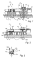
- a cover portion 14 clamps a guide bar 1 to a body 2 by means of a tightening arrangement, comprising two joints 10, 20.
- Each joint includes a first 3 and a second 15 engagement means.
- the first engagement means 3 is a bolt and the second engagement means 15 is a nut.
- Each bolt 3 has a first part 3a and a second part 3b.
- the first part 3a is securely attached to the body 2, e.g. by means of force fit, and the second part 3b extends from the body in a direction perpendicular to the guide bar plane and further through an aperture in the guide bar 1 and through an aperture 14c in the cover portion 14.
- the cover portion 14 has an inner surface 14a, directed towards the body 2, and an outer surface 14b, directed away from the body.
- a threaded part 3c of the second bolt part 3b functioning as an engagement portion for engaging the nut to the bolt, projects at least partly beyond the outer surface 14b of the cover portion.
- the nut 15 is engaged to the threaded part 3c of the bolt 3, and tightened.
- the joint 20 in the right part of figs. 1 and 2 illustrates a condition when the nut 15 and the bolt 3 are not engaged but the nut is captively connected to the holder portion 14.
- the joint 10 in the left part of figs. 1 and 2 illustrates a condition when the nut 3 and the bolt 15 are engaged and the nut 15 is tightened such that the joint clamps the bar 1 firmly between the body 2 and the cover portion 14.
- reference A indicates a first distance, which is the length of thread engagement between the bolt 3 and the nut 15, i.e. the distance in the direction of a nut rotation axis X that the nut 15 has to move in thread engagement with the bolt 3 for firmly clamping the bar 1 between the body 2 and the cover portion 14.
- this second distance B is equal to the distance in the direction of the nut rotation axis X between the position of the nut 15 in the left part of the figure and the position of the nut 15 in the right part of the figure.
- the second distance B is equal to or greater than the first distance A, for allowing the nuts 15 to be loosened separately and independently of each other when detaching the cover from the body.
- the nut 15 comprises a hollow and internally threaded body portion 15b, which is rotatably attached to a holder portion 15a, as shown in fig. 3 .
- the body portion 15b is rotatable compared to the holder portion 15a around the nut rotation axis X.
- the holder portion 15a comprises a substantially circular portion that bears against the body portion 15b, and three attaching portions 15c, formed as legs, extending from the periphery of the substantially circular portion.
- the legs 15c are flat and directed away from the body portion 15b in a direction substantially parallel to the nut rotation axis X.
- each leg 15c a slot extends from an end of each leg distal to the body portion in a direction towards the body portion 15b to a point between the distal end of the leg 15c and the substantially circular portion of the holder portion 15a, such that the slot partly divides each leg 15c into two parallel parts.
- Each parallel part has a protruding portion 15d, shaped as a hook, in the distal end.
- the cover portion 14 has oblong recesses 14e for receiving the legs 15c of the nut holder portion 15a. There is one separate recess 14e for each leg 15c. The recesses 14e are arranged separately from the through aperture 14c of the cover portion, which aperture 14c is arranged for receiving the bolt 3.
- the outer surface 14b of the cover portion 14 has protruding portions 14d arranged to co-operate with the hooks 15d of the nut holder portion legs 15c. The distance between these protruding portions 14d make the width of an opening of the recess 14e smaller than the width of the nut holder portion leg 15c at the position of the hooks 15d, such that the holder portion legs 15c are captivated within the recess 14e.
- each recess 14e is equal to or larger than the length of a holder portion leg 14c.
- the recesses 14e may according to an alternative embodiment extend from the outer surface 14a to the inner surface 14 b of the body, e.g. the recesses may be through apertures.
- each leg 15c makes the structure of the nut holder portion legs 15c resilient.
- the outer ends of the two parallel parts can be pressed towards each other so that it is possible to snap the legs into the openings of the recesses 14e in the cover portion.
- the legs 15c will revert to their original shape.
- the legs 15c allow the nut 15 to move relative the cover portion 14 in a direction of the rotational axis X of the nut.
- the hooks 15d of the legs reaches the protruding portions 14d of the cover portion 14, the protruding portions 14d will co-operate with the hooks 15d such that the movement of the nut 15 is stopped. In this way, the nut 15 is captively attached to the cover portion 14.
- the nut holder portion 15a has three legs 15c and there are three recesses 14e in the cover portion 14 for receiving the legs 15c.
- the number of legs 15c and corresponding recesses 14e may also be one, two, four or more.
- the cross section in fig. 1 is taken along a plane that intersects the centres of the bolts 3.
- the cross section in fig. 2 is taken along a plane that is parallel to the cross section plane in fig. 1 and that intersects a leg 15c of the nut holder portion 15a.
- the operator starts by loosening the nuts 15. Thanks to the second distance B being larger than the first distance A, the length of thread engagement, the nuts 15 can be unscrewed and loosened one at a time.
- the cover 14 including the nuts 15 captively arranged in the cover is removed from the chain saw. Thereafter, the operator removes the old bar 1 from the body 2 and the bolts 3 of the tightening arrangement, and arranges a new bar 1 onto the bolts 3 such that the second part 3b of the bolts passes through the apertures of the new bar 1.
- the cover portion 14 When the new bar 1 has been arranged onto the bolts 3, the cover portion 14 is arranged onto the bolts 3 by leading the bolts through the through apertures 14c of the cover portion.
- the through apertures 14c of the cover portion also function as a guiding means for guiding the cover portion 14 onto the bolts 3 such that the cover portion 14 comes into a correct position and such that the nuts 15 are arranged correctly towards the end of the second parts 3b of the bolts.
- chain saw configurations having break components, such as a break band for a kick-back guard (not shown) mounted in the cover portion it is important to obtain high precision in the position of the cover portion 14.
- the through aperture 14c of the cover portion 14 gets guidance from the second part 3b of the bolt 3.
- the diameters of the second part 3b of the bolt 3 and the through aperture 14c are preferably adapted to achieve a close fit and thereby a sufficient guidance in order to obtain a high precision in the position of the cover portion 4. According to the present embodiment the precision in the position of the cover portion 14 is even further improved by the relatively long contact area, defined by the distance C in Fig. 1 .
- the cover 14 can be arranged onto the bolts 3 such that the cover 14 can be pressed towards the bar 1 and the body 2 before the nuts 15 are tightened. This measure facilitates a correct arrangement of the bar between the cover and the body.
- FIG. 4 An alternative embodiment of the present invention is shown in fig. 4 wherein, as for the embodiment described with reference to figs. 1-3 , a cover portion 4 clamps a guide bar 1 to a body 2 by means of a tightening arrangement, comprising two joints 10, 20.
- Each joint includes a first 3 and a second 5 engagement means.
- the first engagement means 3 is a bolt and the second engagement means 5 is a nut.
- the Joint 10 in the left part of fig. 4 shows a state when the nut 5 is engaged to the bolt 3 so that the bar 1 is firmly clamped between the cover portion 4 and the body 2.
- the Joint 20 in the right part of fig. 4 illustrates a condition when the nut 5 and the bolt 3 are not engaged but the nut is captively connected to the cover portion 4.
- the bolts 3 may be similar to the bolts described with reference to figs 1-3 .
- Each bolt has a first part 3a, securely attached to the body 2, and a second part 3b extending from the body through an aperture in the guide bar 1 and further through an aperture 4c,4g in the cover portion 4.
- the cover portion 4 has an inner surface 4a, directed towards the body, and an outer surface 4b, directed away from the body.
- a plate 4f is attached to the outer surface 4b of the cover portion by means of a screw 6.
- the second part 3b of the bolt extends through an aperture in the plate 4f.
- a threaded part 3c of the second bolt part 3b projects beyond the plate 4f, in a direction away from the cover portion 4.
- the nut 5 is engaged to the threaded part 3c of the bolt 3, and tightened.
- the nut 5 comprises an internally threaded body portion 5c for engaging the threaded part 3c of the bolt.
- the internally threaded body portion is provided with a flange 5d that is adapted to bear against the plate 4f when the nut 5 is tightened.
- the nut also comprises an attaching portion 5a, formed as a neck, adapted to be inserted into the through aperture 4c, 4g of the cover portion 4. The neck projects from the body portion in the direction of the nut rotation axis X from the flange 5d and away from the body portion 5c.
- the neck 5a has a protrusion, 5b formed as a flange arranged at the end distal to the flange 5d.
- the protrusion 5b is adapted to co-operate with at least one edge 4d of the aperture of the plate 4f, the at least one edge defining a diameter of the aperture in the plate 4f, so that the nut remains captively attached to the cover portion 4.
- a nut 5 arranged in this way could rather easily be manufactured with low tolerances.
- the aperture 4c, 4g in the cover portion has two parts; an inner part 4g closest to the inner surface 4a of the cover portion 4, and an outer part 4c closest to the outer surface 4b of the cover portion 4.
- the diameter of the inner part 4g is smaller than the diameter of the outer part 4c.
- the outer part 4c is arranged as a recess in the aperture 4c, 4g. More specifically, the diameter of the inner part 4g is equal to or slightly larger than the diameter of the second part 3b of the bolt and the diameter of the outer part 4c is equal to or larger than the diameter of the protrusion 5b of the nut neck 5a.
- the outer part 4c of the aperture 4c, 4g has a larger diameter than the inner part 4g for being able to receive the nut neck 5a with its protrusion 5b.
- the inner part 4g also functions as a guide for the cover portion 4.
- a guide for the cover portion 4 In chain saw configurations having break components, such as a break band for a kick-back guard (not shown), mounted in the cover portion it is important to obtain high precision in the position of the cover portion 4.
- the inner part 4g of the aperture 4c, 4g gets guidance from the second part 3b of the bolt 3.
- the diameters of the the second part 3b of the bolt 3 and the inner part 4g of the aperture 4c, 4g are preferably adapted to achieve a close fit and thereby a sufficient guidance in order to obtain a high precision in the position of the cover portion 4.
- the diameter of the aperture in the plate 4f is slightly smaller than the diameter of the outer part 4c of the through aperture 4c, 4g of the cover portion 4, such that the edge 4d of the plate 4f aperture partly covers the opening of the aperture 4c, 4g in the cover portion 4.
- reference A indicates a first distance, which is the length of thread engagement between the bolt 3 and the nut 5, i.e. the distance in the direction of the nut rotation axis X that the nut 15 has to move in thread engagement with the bolt 3 for firmly clamping the bar 1 between the body 2 and the cover portion 14.
- first distance is the length of thread engagement between the bolt 3 and the nut 5, i.e. the distance in the direction of the nut rotation axis X that the nut 15 has to move in thread engagement with the bolt 3 for firmly clamping the bar 1 between the body 2 and the cover portion 14.
- this second distance B is equal to the distance in the direction of the nut rotation axis X between the position of the nut 5 of the joint 10 in the left part of the figure and the position of the nut 5 of the joint 20 in the right part of the figure.
- the second distance B is equal to or greater than the first distance A, for allowing the nuts 5 to be loosened separately and independently of each other.
- Reference C indicates the thickness of the cover portion 4, i.e. a distance between the outer surface 4b and inner surface 4a of the cover portion.
- the walls of the inner part 4g of the through aperture will function as a guiding means for guiding the bolt 3 towards the nut 5 when the cover portion 4 is lead on to the bolt 3 such that the bar 1 is clamped between the cover portion 4 and the body 2.
- Reference D indicates a length of the inner part 4g of the through aperture 4c, 4g in the cover portion 4 in the direction of the nut rotation axis X functioning as a guiding means, i.e. a guiding length.
- the aperture in the plate 4f may be oblong having a smallest diameter similar to the diameter between the edges 4d of the plate 4f and a largest diameter larger than the diameter of the nut neck 5a at the protrusions 5b.
- the plate When the plate is attached to the cover portion by means of the screw 6 such that the plate bears against the outer surface 4b of the cover portion 4, and the nut neck 5a extends into the aperture 4c, 4g, the nut 5 can not be tilted and is thus captively attached to the cover portion.
- the aperture in the plate 4f may be circular having a diameter similar to the distance between the edges 4d of the plate.
- the nut neck may have slots extending in the direction of the nut rotation axis X, the slots making the structure of the nut neck 5a resilient.
- the nut neck 5a will revert to its original shape, and the nut 5 is captively connected to the plate 4f.
- the plate 4f can be a separate plate or a part of an already existing part of the hand-held motor-driven tool, such as a spike or spike bumper of a chain saw.
- the tool is described as a chain saw.
- the tool may be any kind of hand-held motor-driven tool in which a bar is clamped between a cover and a body, such as a hedge trimmer, clearing saw, trimmer, pole saw or a power cutter.
Landscapes
- Engineering & Computer Science (AREA)
- General Engineering & Computer Science (AREA)
- Mechanical Engineering (AREA)
- Life Sciences & Earth Sciences (AREA)
- Wood Science & Technology (AREA)
- Forests & Forestry (AREA)
- Sawing (AREA)
- Clamps And Clips (AREA)
Priority Applications (2)
| Application Number | Priority Date | Filing Date | Title |
|---|---|---|---|
| EP14172060.7A EP2777901B1 (fr) | 2007-10-12 | 2007-10-12 | Dispositif de fixation pour outils électro-portatifs |
| PL14172060T PL2777901T3 (pl) | 2007-10-12 | 2007-10-12 | Układ mocujący dla narzędzi ręcznych napędzanych silnikowo |
Applications Claiming Priority (3)
| Application Number | Priority Date | Filing Date | Title |
|---|---|---|---|
| EP07835097.2A EP2207654B1 (fr) | 2007-10-12 | 2007-10-12 | Dispositif de fixation pour machines-outils portatives |
| EP14172060.7A EP2777901B1 (fr) | 2007-10-12 | 2007-10-12 | Dispositif de fixation pour outils électro-portatifs |
| PCT/SE2007/000895 WO2009048356A1 (fr) | 2007-10-12 | 2007-10-12 | Dispositif de fixation pour machines-outils portatives |
Related Parent Applications (2)
| Application Number | Title | Priority Date | Filing Date |
|---|---|---|---|
| EP07835097.2A Division EP2207654B1 (fr) | 2007-10-12 | 2007-10-12 | Dispositif de fixation pour machines-outils portatives |
| EP07835097.2A Division-Into EP2207654B1 (fr) | 2007-10-12 | 2007-10-12 | Dispositif de fixation pour machines-outils portatives |
Publications (2)
| Publication Number | Publication Date |
|---|---|
| EP2777901A1 true EP2777901A1 (fr) | 2014-09-17 |
| EP2777901B1 EP2777901B1 (fr) | 2017-05-17 |
Family
ID=40549380
Family Applications (2)
| Application Number | Title | Priority Date | Filing Date |
|---|---|---|---|
| EP07835097.2A Active EP2207654B1 (fr) | 2007-10-12 | 2007-10-12 | Dispositif de fixation pour machines-outils portatives |
| EP14172060.7A Active EP2777901B1 (fr) | 2007-10-12 | 2007-10-12 | Dispositif de fixation pour outils électro-portatifs |
Family Applications Before (1)
| Application Number | Title | Priority Date | Filing Date |
|---|---|---|---|
| EP07835097.2A Active EP2207654B1 (fr) | 2007-10-12 | 2007-10-12 | Dispositif de fixation pour machines-outils portatives |
Country Status (7)
| Country | Link |
|---|---|
| US (3) | US8615889B2 (fr) |
| EP (2) | EP2207654B1 (fr) |
| JP (1) | JP5539885B2 (fr) |
| CN (1) | CN101821067B (fr) |
| CA (1) | CA2702207C (fr) |
| PL (1) | PL2777901T3 (fr) |
| WO (1) | WO2009048356A1 (fr) |
Cited By (3)
| Publication number | Priority date | Publication date | Assignee | Title |
|---|---|---|---|---|
| US9573208B2 (en) | 2013-03-29 | 2017-02-21 | Makita Corporation | Portable working machine |
| EP3736093A1 (fr) | 2019-05-10 | 2020-11-11 | Robert Bosch GmbH | Dispositif de fixation permettant de fixer un guide de tronçonneuse |
| EP3237158B1 (fr) * | 2014-12-22 | 2021-07-28 | Husqvarna AB | Dispositif de retenue de fixation pour une couverture de protection |
Families Citing this family (18)
| Publication number | Priority date | Publication date | Assignee | Title |
|---|---|---|---|---|
| PL2777901T3 (pl) | 2007-10-12 | 2017-10-31 | Husqvarna Ab | Układ mocujący dla narzędzi ręcznych napędzanych silnikowo |
| WO2012144942A1 (fr) * | 2011-04-21 | 2012-10-26 | Husqvarna Ab | Ensemble de serrage pour scie à chaîne |
| JP6137467B2 (ja) * | 2013-04-25 | 2017-05-31 | 日立工機株式会社 | チェーンソー |
| FR3006723B1 (fr) | 2013-06-11 | 2015-12-04 | Snecma | Dispositif de fixation de deux pieces entre elles |
| JP6152325B2 (ja) | 2013-09-11 | 2017-06-21 | 株式会社やまびこ | 携帯型動力作業機における締付用ナットの落ち止め構造及び締付用ナット係留部材 |
| US10945381B1 (en) | 2014-07-02 | 2021-03-16 | Outdoor Product Innovations, Inc. | Modular tools with detachable coupling |
| US10091948B2 (en) * | 2014-07-02 | 2018-10-09 | Wicked Tuff Gear, Llc | Light pole saw |
| CN104500521B (zh) * | 2014-11-26 | 2016-04-06 | 株洲南车时代电气股份有限公司 | 一种使用沉头螺钉的面板与柜体连接结构 |
| JP6588326B2 (ja) | 2015-12-17 | 2019-10-09 | 株式会社やまびこ | 携帯型動力作業機における締付用ナットの落ち止め構造及びその締付用ナットの組付方法 |
| DE102016000718A1 (de) * | 2016-01-23 | 2017-07-27 | Andreas Stihl Ag & Co. Kg | Handgeführtes Arbeitsgerät mit einer Führungsschiene |
| CN105918072A (zh) * | 2016-06-20 | 2016-09-07 | 常州格力博有限公司 | 链锯 |
| SE540728C2 (en) * | 2016-12-01 | 2018-10-23 | Husqvarna Ab | A screw-retaining device and screw-retaining kit |
| DE102017007051B4 (de) * | 2017-07-26 | 2020-06-18 | Sumitomo Riko Company Limited | Selbst positionierende Verschraubung |
| US10221881B1 (en) * | 2017-09-28 | 2019-03-05 | Siemens Industry, Inc. | Fastener retainers, thumb nut retainer assemblies, power distribution enclosure assemblies, and connection methods |
| WO2020055624A1 (fr) * | 2018-09-14 | 2020-03-19 | Illinois Tool Works Inc. | Système de montage pour profilé de boîte |
| JP6641675B1 (ja) * | 2018-12-05 | 2020-02-05 | イモア株式会社 | 建設現場用敷き鉄板のジョイント |
| CN110814183A (zh) * | 2019-12-16 | 2020-02-21 | 苏州聚昶精密五金机械有限公司 | 一种防震式冲压模具 |
| WO2022051468A1 (fr) | 2020-09-04 | 2022-03-10 | Milwaukee Electric Tool Corporation | Scie à chaîne |
Citations (7)
| Publication number | Priority date | Publication date | Assignee | Title |
|---|---|---|---|---|
| JPS6038701U (ja) * | 1983-08-25 | 1985-03-18 | 小松ゼノア株式会社 | チエンソ− |
| DE3807001A1 (de) * | 1988-03-01 | 1989-09-14 | Hubert Combe | Vorrichtung zur verbindung von zwei werkstuecken |
| US5497557A (en) | 1993-10-13 | 1996-03-12 | Aktiebolaget Electrolux | Chain stretching device for a chain saw |
| US5522143A (en) * | 1993-11-12 | 1996-06-04 | Andreas Stihl | Tensioning arrangement for a saw chain of a motor-driven chain saw |
| US20010042311A1 (en) | 2000-05-19 | 2001-11-22 | Makita Corporation | Chain saw with an improved chain tensioning arrangement |
| US6564459B1 (en) * | 1999-07-07 | 2003-05-20 | Robert Bosch Gmbh | Chain saw |
| JP2006266411A (ja) * | 2005-03-24 | 2006-10-05 | Nec Corp | ねじ脱落防止機構 |
Family Cites Families (19)
| Publication number | Priority date | Publication date | Assignee | Title |
|---|---|---|---|---|
| GB1136128A (en) * | 1966-03-25 | 1968-12-11 | Carr Fastener Co Ltd | Sheet metal nut device |
| US3611864A (en) * | 1969-08-07 | 1971-10-12 | Air Logistics Corp | Snap-in nut plate |
| US4219064A (en) * | 1978-06-23 | 1980-08-26 | Shur-Lok Corporation | Non-marring clip nut |
| US5039264A (en) * | 1988-12-01 | 1991-08-13 | The Monadnock Company | Scratch resistant clip-on nut |
| US5326206A (en) * | 1993-04-19 | 1994-07-05 | Northrop Corporation | Method for compensating for bolt hole misalignment and bolt assemblies therefor |
| DE29909645U1 (de) * | 1999-06-02 | 1999-09-16 | Narex Česká Lípa a.s., Česká Lípa | Schraubverbindung, insbesondere zum Befestigen des Schwerts einer Kettensäge |
| US6095734A (en) * | 1999-09-21 | 2000-08-01 | Transtechnology Corp. | Pushnut |
| DE19963650A1 (de) * | 1999-12-29 | 2001-07-12 | Bosch Gmbh Robert | Kettensäge |
| ITVE20000042A1 (it) * | 2000-10-17 | 2002-04-17 | Alpina Professional & Garden S | Dispositivo di tensionamento, particolarmente per motoseghe a catena |
| JP2003222112A (ja) * | 2002-01-31 | 2003-08-08 | Nippon Pop Rivets & Fasteners Ltd | スクリューグロメット |
| US6688825B1 (en) * | 2002-02-25 | 2004-02-10 | Alpha Stamping Company | Nut and retainer fastener assembly for securing a nut to a panel, and method of fastener assembly manufacture |
| US20050169727A1 (en) * | 2004-02-02 | 2005-08-04 | Cosenza Frank J. | Fastener component |
| US7481000B2 (en) * | 2005-01-10 | 2009-01-27 | Husqvarna Outdoor Products Inc. | Chainsaw bar adjustment assembly with breakaway adjustment pin |
| US7155832B2 (en) * | 2005-03-01 | 2007-01-02 | Husqvarna Outdoor Products Inc. | Chain saw with tool-less chain tensioner and guide bar lock |
| DE102006037329B4 (de) * | 2006-08-10 | 2020-01-02 | Andreas Stihl Ag & Co. Kg | Kettenraddeckelanordnung einer handgeführten Kettensäge |
| US7743513B1 (en) * | 2006-10-31 | 2010-06-29 | Mtd Products Inc | Chainsaw tensioning device |
| PL2777901T3 (pl) | 2007-10-12 | 2017-10-31 | Husqvarna Ab | Układ mocujący dla narzędzi ręcznych napędzanych silnikowo |
| CN101841987A (zh) * | 2009-03-21 | 2010-09-22 | 富准精密工业(深圳)有限公司 | 散热装置及其扣具 |
| DE102010012748B4 (de) * | 2010-03-25 | 2020-01-02 | Andreas Stihl Ag & Co. Kg | Kettensäge |
-
2007
- 2007-10-12 PL PL14172060T patent/PL2777901T3/pl unknown
- 2007-10-12 EP EP07835097.2A patent/EP2207654B1/fr active Active
- 2007-10-12 EP EP14172060.7A patent/EP2777901B1/fr active Active
- 2007-10-12 CN CN2007801010579A patent/CN101821067B/zh active Active
- 2007-10-12 JP JP2010528826A patent/JP5539885B2/ja active Active
- 2007-10-12 WO PCT/SE2007/000895 patent/WO2009048356A1/fr active Application Filing
- 2007-10-12 US US12/682,765 patent/US8615889B2/en active Active
- 2007-10-12 CA CA2702207A patent/CA2702207C/fr active Active
-
2010
- 2010-04-12 US US12/758,290 patent/US8740529B2/en active Active
-
2013
- 2013-12-30 US US14/144,392 patent/US20140109416A1/en not_active Abandoned
Patent Citations (7)
| Publication number | Priority date | Publication date | Assignee | Title |
|---|---|---|---|---|
| JPS6038701U (ja) * | 1983-08-25 | 1985-03-18 | 小松ゼノア株式会社 | チエンソ− |
| DE3807001A1 (de) * | 1988-03-01 | 1989-09-14 | Hubert Combe | Vorrichtung zur verbindung von zwei werkstuecken |
| US5497557A (en) | 1993-10-13 | 1996-03-12 | Aktiebolaget Electrolux | Chain stretching device for a chain saw |
| US5522143A (en) * | 1993-11-12 | 1996-06-04 | Andreas Stihl | Tensioning arrangement for a saw chain of a motor-driven chain saw |
| US6564459B1 (en) * | 1999-07-07 | 2003-05-20 | Robert Bosch Gmbh | Chain saw |
| US20010042311A1 (en) | 2000-05-19 | 2001-11-22 | Makita Corporation | Chain saw with an improved chain tensioning arrangement |
| JP2006266411A (ja) * | 2005-03-24 | 2006-10-05 | Nec Corp | ねじ脱落防止機構 |
Cited By (5)
| Publication number | Priority date | Publication date | Assignee | Title |
|---|---|---|---|---|
| US9573208B2 (en) | 2013-03-29 | 2017-02-21 | Makita Corporation | Portable working machine |
| DE102014004063B4 (de) | 2013-03-29 | 2023-11-09 | Makita Corporation | Tragbare Arbeitsmaschine |
| EP3237158B1 (fr) * | 2014-12-22 | 2021-07-28 | Husqvarna AB | Dispositif de retenue de fixation pour une couverture de protection |
| EP3736093A1 (fr) | 2019-05-10 | 2020-11-11 | Robert Bosch GmbH | Dispositif de fixation permettant de fixer un guide de tronçonneuse |
| DE102019206767A1 (de) * | 2019-05-10 | 2020-11-12 | Robert Bosch Gmbh | Befestigungsvorrichtung zum Befestigen eines Kettensägenschwerts |
Also Published As
| Publication number | Publication date |
|---|---|
| EP2777901B1 (fr) | 2017-05-17 |
| US20140109416A1 (en) | 2014-04-24 |
| CA2702207A1 (fr) | 2009-04-16 |
| US20100275451A1 (en) | 2010-11-04 |
| US20100232904A1 (en) | 2010-09-16 |
| EP2207654B1 (fr) | 2015-03-18 |
| WO2009048356A1 (fr) | 2009-04-16 |
| US8615889B2 (en) | 2013-12-31 |
| US8740529B2 (en) | 2014-06-03 |
| CA2702207C (fr) | 2014-06-17 |
| EP2207654A4 (fr) | 2013-12-25 |
| CN101821067B (zh) | 2012-08-15 |
| JP2011500338A (ja) | 2011-01-06 |
| JP5539885B2 (ja) | 2014-07-02 |
| PL2777901T3 (pl) | 2017-10-31 |
| CN101821067A (zh) | 2010-09-01 |
| EP2207654A1 (fr) | 2010-07-21 |
Similar Documents
| Publication | Publication Date | Title |
|---|---|---|
| CA2702207C (fr) | Dispositif de fixation pour machines-outils portatives | |
| US10792801B2 (en) | Oscillating power tools and accessories | |
| US6213677B1 (en) | Joint mechanism for mowing machine | |
| US7127877B2 (en) | Universal mower blade | |
| EP3237158B1 (fr) | Dispositif de retenue de fixation pour une couverture de protection | |
| US5035550A (en) | Hole saw | |
| US9993937B2 (en) | Power tool | |
| EP2608930A1 (fr) | Machine-outil portative à col de serrage | |
| JP3182895U (ja) | 可変式穴開け装置 | |
| US4850109A (en) | Adaptor to convert a chain saw to a circular saw | |
| US7328501B2 (en) | Apparatus, a system for separating a gear from a camshaft | |
| JP5833620B2 (ja) | 手持ち式電動工具のための取付装置 | |
| WO2018003368A1 (fr) | Tronçonneuse | |
| CA2236657C (fr) | Systeme de montage de dents de scie et dents de scie | |
| JP3618820B2 (ja) | 往復動工具のシャフト支持装置 | |
| JP2013031931A (ja) | 携帯式作業機 | |
| CA2422716A1 (fr) | Scie circulaire a dents et supports pour tete d'abattage | |
| KR0124249Y1 (ko) | 톱날 교체식 접는 톱 | |
| EP2644913A2 (fr) | Outil de maintien, système et procédé | |
| JP2014108070A (ja) | 作業機 | |
| KR19990002797U (ko) | 자동차 조립용 볼트 | |
| JP2009028014A (ja) | 刈払機 |
Legal Events
| Date | Code | Title | Description |
|---|---|---|---|
| 17P | Request for examination filed |
Effective date: 20140612 |
|
| AC | Divisional application: reference to earlier application |
Ref document number: 2207654 Country of ref document: EP Kind code of ref document: P |
|
| AK | Designated contracting states |
Kind code of ref document: A1 Designated state(s): AT BE BG CH CY CZ DE DK EE ES FI FR GB GR HU IE IS IT LI LT LU LV MC MT NL PL PT RO SE SI SK TR |
|
| PUAI | Public reference made under article 153(3) epc to a published international application that has entered the european phase |
Free format text: ORIGINAL CODE: 0009012 |
|
| GRAP | Despatch of communication of intention to grant a patent |
Free format text: ORIGINAL CODE: EPIDOSNIGR1 |
|
| INTG | Intention to grant announced |
Effective date: 20161215 |
|
| RIN1 | Information on inventor provided before grant (corrected) |
Inventor name: MARTINSSON, PAER |
|
| GRAS | Grant fee paid |
Free format text: ORIGINAL CODE: EPIDOSNIGR3 |
|
| GRAA | (expected) grant |
Free format text: ORIGINAL CODE: 0009210 |
|
| AC | Divisional application: reference to earlier application |
Ref document number: 2207654 Country of ref document: EP Kind code of ref document: P |
|
| AK | Designated contracting states |
Kind code of ref document: B1 Designated state(s): AT BE BG CH CY CZ DE DK EE ES FI FR GB GR HU IE IS IT LI LT LU LV MC MT NL PL PT RO SE SI SK TR |
|
| REG | Reference to a national code |
Ref country code: GB Ref legal event code: FG4D |
|
| REG | Reference to a national code |
Ref country code: CH Ref legal event code: EP |
|
| REG | Reference to a national code |
Ref country code: IE Ref legal event code: FG4D |
|
| REG | Reference to a national code |
Ref country code: AT Ref legal event code: REF Ref document number: 894053 Country of ref document: AT Kind code of ref document: T Effective date: 20170615 |
|
| REG | Reference to a national code |
Ref country code: DE Ref legal event code: R096 Ref document number: 602007051088 Country of ref document: DE |
|
| REG | Reference to a national code |
Ref country code: SE Ref legal event code: TRGR |
|
| REG | Reference to a national code |
Ref country code: NL Ref legal event code: MP Effective date: 20170517 |
|
| REG | Reference to a national code |
Ref country code: LT Ref legal event code: MG4D |
|
| PG25 | Lapsed in a contracting state [announced via postgrant information from national office to epo] |
Ref country code: GR Free format text: LAPSE BECAUSE OF FAILURE TO SUBMIT A TRANSLATION OF THE DESCRIPTION OR TO PAY THE FEE WITHIN THE PRESCRIBED TIME-LIMIT Effective date: 20170818 Ref country code: LT Free format text: LAPSE BECAUSE OF FAILURE TO SUBMIT A TRANSLATION OF THE DESCRIPTION OR TO PAY THE FEE WITHIN THE PRESCRIBED TIME-LIMIT Effective date: 20170517 Ref country code: ES Free format text: LAPSE BECAUSE OF FAILURE TO SUBMIT A TRANSLATION OF THE DESCRIPTION OR TO PAY THE FEE WITHIN THE PRESCRIBED TIME-LIMIT Effective date: 20170517 |
|
| PG25 | Lapsed in a contracting state [announced via postgrant information from national office to epo] |
Ref country code: NL Free format text: LAPSE BECAUSE OF FAILURE TO SUBMIT A TRANSLATION OF THE DESCRIPTION OR TO PAY THE FEE WITHIN THE PRESCRIBED TIME-LIMIT Effective date: 20170517 Ref country code: IS Free format text: LAPSE BECAUSE OF FAILURE TO SUBMIT A TRANSLATION OF THE DESCRIPTION OR TO PAY THE FEE WITHIN THE PRESCRIBED TIME-LIMIT Effective date: 20170917 Ref country code: BG Free format text: LAPSE BECAUSE OF FAILURE TO SUBMIT A TRANSLATION OF THE DESCRIPTION OR TO PAY THE FEE WITHIN THE PRESCRIBED TIME-LIMIT Effective date: 20170817 Ref country code: LV Free format text: LAPSE BECAUSE OF FAILURE TO SUBMIT A TRANSLATION OF THE DESCRIPTION OR TO PAY THE FEE WITHIN THE PRESCRIBED TIME-LIMIT Effective date: 20170517 |
|
| PG25 | Lapsed in a contracting state [announced via postgrant information from national office to epo] |
Ref country code: CZ Free format text: LAPSE BECAUSE OF FAILURE TO SUBMIT A TRANSLATION OF THE DESCRIPTION OR TO PAY THE FEE WITHIN THE PRESCRIBED TIME-LIMIT Effective date: 20170517 Ref country code: DK Free format text: LAPSE BECAUSE OF FAILURE TO SUBMIT A TRANSLATION OF THE DESCRIPTION OR TO PAY THE FEE WITHIN THE PRESCRIBED TIME-LIMIT Effective date: 20170517 Ref country code: SK Free format text: LAPSE BECAUSE OF FAILURE TO SUBMIT A TRANSLATION OF THE DESCRIPTION OR TO PAY THE FEE WITHIN THE PRESCRIBED TIME-LIMIT Effective date: 20170517 Ref country code: EE Free format text: LAPSE BECAUSE OF FAILURE TO SUBMIT A TRANSLATION OF THE DESCRIPTION OR TO PAY THE FEE WITHIN THE PRESCRIBED TIME-LIMIT Effective date: 20170517 Ref country code: RO Free format text: LAPSE BECAUSE OF FAILURE TO SUBMIT A TRANSLATION OF THE DESCRIPTION OR TO PAY THE FEE WITHIN THE PRESCRIBED TIME-LIMIT Effective date: 20170517 |
|
| REG | Reference to a national code |
Ref country code: DE Ref legal event code: R097 Ref document number: 602007051088 Country of ref document: DE |
|
| PG25 | Lapsed in a contracting state [announced via postgrant information from national office to epo] |
Ref country code: IT Free format text: LAPSE BECAUSE OF FAILURE TO SUBMIT A TRANSLATION OF THE DESCRIPTION OR TO PAY THE FEE WITHIN THE PRESCRIBED TIME-LIMIT Effective date: 20170517 |
|
| PLBE | No opposition filed within time limit |
Free format text: ORIGINAL CODE: 0009261 |
|
| STAA | Information on the status of an ep patent application or granted ep patent |
Free format text: STATUS: NO OPPOSITION FILED WITHIN TIME LIMIT |
|
| 26N | No opposition filed |
Effective date: 20180220 |
|
| REG | Reference to a national code |
Ref country code: DE Ref legal event code: R119 Ref document number: 602007051088 Country of ref document: DE |
|
| PG25 | Lapsed in a contracting state [announced via postgrant information from national office to epo] |
Ref country code: SI Free format text: LAPSE BECAUSE OF FAILURE TO SUBMIT A TRANSLATION OF THE DESCRIPTION OR TO PAY THE FEE WITHIN THE PRESCRIBED TIME-LIMIT Effective date: 20170517 Ref country code: MC Free format text: LAPSE BECAUSE OF FAILURE TO SUBMIT A TRANSLATION OF THE DESCRIPTION OR TO PAY THE FEE WITHIN THE PRESCRIBED TIME-LIMIT Effective date: 20170517 |
|
| REG | Reference to a national code |
Ref country code: CH Ref legal event code: PL |
|
| REG | Reference to a national code |
Ref country code: IE Ref legal event code: MM4A |
|
| REG | Reference to a national code |
Ref country code: FR Ref legal event code: ST Effective date: 20180629 |
|
| PG25 | Lapsed in a contracting state [announced via postgrant information from national office to epo] |
Ref country code: DE Free format text: LAPSE BECAUSE OF NON-PAYMENT OF DUE FEES Effective date: 20180501 Ref country code: CH Free format text: LAPSE BECAUSE OF NON-PAYMENT OF DUE FEES Effective date: 20171031 Ref country code: LU Free format text: LAPSE BECAUSE OF NON-PAYMENT OF DUE FEES Effective date: 20171012 Ref country code: LI Free format text: LAPSE BECAUSE OF NON-PAYMENT OF DUE FEES Effective date: 20171031 |
|
| REG | Reference to a national code |
Ref country code: BE Ref legal event code: MM Effective date: 20171031 |
|
| PG25 | Lapsed in a contracting state [announced via postgrant information from national office to epo] |
Ref country code: BE Free format text: LAPSE BECAUSE OF NON-PAYMENT OF DUE FEES Effective date: 20171031 Ref country code: FR Free format text: LAPSE BECAUSE OF NON-PAYMENT OF DUE FEES Effective date: 20171031 |
|
| PG25 | Lapsed in a contracting state [announced via postgrant information from national office to epo] |
Ref country code: MT Free format text: LAPSE BECAUSE OF NON-PAYMENT OF DUE FEES Effective date: 20171012 |
|
| PG25 | Lapsed in a contracting state [announced via postgrant information from national office to epo] |
Ref country code: IE Free format text: LAPSE BECAUSE OF NON-PAYMENT OF DUE FEES Effective date: 20171012 |
|
| PG25 | Lapsed in a contracting state [announced via postgrant information from national office to epo] |
Ref country code: HU Free format text: LAPSE BECAUSE OF FAILURE TO SUBMIT A TRANSLATION OF THE DESCRIPTION OR TO PAY THE FEE WITHIN THE PRESCRIBED TIME-LIMIT; INVALID AB INITIO Effective date: 20071012 |
|
| REG | Reference to a national code |
Ref country code: AT Ref legal event code: UEP Ref document number: 894053 Country of ref document: AT Kind code of ref document: T Effective date: 20170517 |
|
| PG25 | Lapsed in a contracting state [announced via postgrant information from national office to epo] |
Ref country code: CY Free format text: LAPSE BECAUSE OF NON-PAYMENT OF DUE FEES Effective date: 20170517 |
|
| PG25 | Lapsed in a contracting state [announced via postgrant information from national office to epo] |
Ref country code: TR Free format text: LAPSE BECAUSE OF FAILURE TO SUBMIT A TRANSLATION OF THE DESCRIPTION OR TO PAY THE FEE WITHIN THE PRESCRIBED TIME-LIMIT Effective date: 20170517 |
|
| PG25 | Lapsed in a contracting state [announced via postgrant information from national office to epo] |
Ref country code: PT Free format text: LAPSE BECAUSE OF FAILURE TO SUBMIT A TRANSLATION OF THE DESCRIPTION OR TO PAY THE FEE WITHIN THE PRESCRIBED TIME-LIMIT Effective date: 20170517 |
|
| PGFP | Annual fee paid to national office [announced via postgrant information from national office to epo] |
Ref country code: SE Payment date: 20220912 Year of fee payment: 16 Ref country code: FI Payment date: 20220922 Year of fee payment: 16 |
|
| PGFP | Annual fee paid to national office [announced via postgrant information from national office to epo] |
Ref country code: PL Payment date: 20220915 Year of fee payment: 16 |
|
| PGFP | Annual fee paid to national office [announced via postgrant information from national office to epo] |
Ref country code: GB Payment date: 20221012 Year of fee payment: 16 |
|
| P01 | Opt-out of the competence of the unified patent court (upc) registered |
Effective date: 20230419 |
|
| PGFP | Annual fee paid to national office [announced via postgrant information from national office to epo] |
Ref country code: AT Payment date: 20230920 Year of fee payment: 17 |
|
| REG | Reference to a national code |
Ref country code: SE Ref legal event code: EUG |
|
| GBPC | Gb: european patent ceased through non-payment of renewal fee |
Effective date: 20231012 |
|
| PG25 | Lapsed in a contracting state [announced via postgrant information from national office to epo] |
Ref country code: GB Free format text: LAPSE BECAUSE OF NON-PAYMENT OF DUE FEES Effective date: 20231012 |
|
| PG25 | Lapsed in a contracting state [announced via postgrant information from national office to epo] |
Ref country code: GB Free format text: LAPSE BECAUSE OF NON-PAYMENT OF DUE FEES Effective date: 20231012 Ref country code: FI Free format text: LAPSE BECAUSE OF NON-PAYMENT OF DUE FEES Effective date: 20231012 |
|
| PG25 | Lapsed in a contracting state [announced via postgrant information from national office to epo] |
Ref country code: SE Free format text: LAPSE BECAUSE OF NON-PAYMENT OF DUE FEES Effective date: 20231013 |