EP2777615A1 - Prosthesis for atraumatically grasping intralumenal tissue - Google Patents
Prosthesis for atraumatically grasping intralumenal tissue Download PDFInfo
- Publication number
- EP2777615A1 EP2777615A1 EP14159090.1A EP14159090A EP2777615A1 EP 2777615 A1 EP2777615 A1 EP 2777615A1 EP 14159090 A EP14159090 A EP 14159090A EP 2777615 A1 EP2777615 A1 EP 2777615A1
- Authority
- EP
- European Patent Office
- Prior art keywords
- frame
- anchors
- prosthesis
- distal
- proximal
- Prior art date
- Legal status (The legal status is an assumption and is not a legal conclusion. Google has not performed a legal analysis and makes no representation as to the accuracy of the status listed.)
- Granted
Links
Images



Classifications
-
- A—HUMAN NECESSITIES
- A61—MEDICAL OR VETERINARY SCIENCE; HYGIENE
- A61F—FILTERS IMPLANTABLE INTO BLOOD VESSELS; PROSTHESES; DEVICES PROVIDING PATENCY TO, OR PREVENTING COLLAPSING OF, TUBULAR STRUCTURES OF THE BODY, e.g. STENTS; ORTHOPAEDIC, NURSING OR CONTRACEPTIVE DEVICES; FOMENTATION; TREATMENT OR PROTECTION OF EYES OR EARS; BANDAGES, DRESSINGS OR ABSORBENT PADS; FIRST-AID KITS
- A61F2/00—Filters implantable into blood vessels; Prostheses, i.e. artificial substitutes or replacements for parts of the body; Appliances for connecting them with the body; Devices providing patency to, or preventing collapsing of, tubular structures of the body, e.g. stents
- A61F2/02—Prostheses implantable into the body
- A61F2/24—Heart valves ; Vascular valves, e.g. venous valves; Heart implants, e.g. passive devices for improving the function of the native valve or the heart muscle; Transmyocardial revascularisation [TMR] devices; Valves implantable in the body
- A61F2/2409—Support rings therefor, e.g. for connecting valves to tissue
-
- A—HUMAN NECESSITIES
- A61—MEDICAL OR VETERINARY SCIENCE; HYGIENE
- A61F—FILTERS IMPLANTABLE INTO BLOOD VESSELS; PROSTHESES; DEVICES PROVIDING PATENCY TO, OR PREVENTING COLLAPSING OF, TUBULAR STRUCTURES OF THE BODY, e.g. STENTS; ORTHOPAEDIC, NURSING OR CONTRACEPTIVE DEVICES; FOMENTATION; TREATMENT OR PROTECTION OF EYES OR EARS; BANDAGES, DRESSINGS OR ABSORBENT PADS; FIRST-AID KITS
- A61F2/00—Filters implantable into blood vessels; Prostheses, i.e. artificial substitutes or replacements for parts of the body; Appliances for connecting them with the body; Devices providing patency to, or preventing collapsing of, tubular structures of the body, e.g. stents
- A61F2/02—Prostheses implantable into the body
- A61F2/24—Heart valves ; Vascular valves, e.g. venous valves; Heart implants, e.g. passive devices for improving the function of the native valve or the heart muscle; Transmyocardial revascularisation [TMR] devices; Valves implantable in the body
- A61F2/2412—Heart valves ; Vascular valves, e.g. venous valves; Heart implants, e.g. passive devices for improving the function of the native valve or the heart muscle; Transmyocardial revascularisation [TMR] devices; Valves implantable in the body with soft flexible valve members, e.g. tissue valves shaped like natural valves
- A61F2/2418—Scaffolds therefor, e.g. support stents
-
- A—HUMAN NECESSITIES
- A61—MEDICAL OR VETERINARY SCIENCE; HYGIENE
- A61F—FILTERS IMPLANTABLE INTO BLOOD VESSELS; PROSTHESES; DEVICES PROVIDING PATENCY TO, OR PREVENTING COLLAPSING OF, TUBULAR STRUCTURES OF THE BODY, e.g. STENTS; ORTHOPAEDIC, NURSING OR CONTRACEPTIVE DEVICES; FOMENTATION; TREATMENT OR PROTECTION OF EYES OR EARS; BANDAGES, DRESSINGS OR ABSORBENT PADS; FIRST-AID KITS
- A61F2/00—Filters implantable into blood vessels; Prostheses, i.e. artificial substitutes or replacements for parts of the body; Appliances for connecting them with the body; Devices providing patency to, or preventing collapsing of, tubular structures of the body, e.g. stents
- A61F2/02—Prostheses implantable into the body
- A61F2/24—Heart valves ; Vascular valves, e.g. venous valves; Heart implants, e.g. passive devices for improving the function of the native valve or the heart muscle; Transmyocardial revascularisation [TMR] devices; Valves implantable in the body
-
- A—HUMAN NECESSITIES
- A61—MEDICAL OR VETERINARY SCIENCE; HYGIENE
- A61F—FILTERS IMPLANTABLE INTO BLOOD VESSELS; PROSTHESES; DEVICES PROVIDING PATENCY TO, OR PREVENTING COLLAPSING OF, TUBULAR STRUCTURES OF THE BODY, e.g. STENTS; ORTHOPAEDIC, NURSING OR CONTRACEPTIVE DEVICES; FOMENTATION; TREATMENT OR PROTECTION OF EYES OR EARS; BANDAGES, DRESSINGS OR ABSORBENT PADS; FIRST-AID KITS
- A61F2/00—Filters implantable into blood vessels; Prostheses, i.e. artificial substitutes or replacements for parts of the body; Appliances for connecting them with the body; Devices providing patency to, or preventing collapsing of, tubular structures of the body, e.g. stents
- A61F2/02—Prostheses implantable into the body
- A61F2/24—Heart valves ; Vascular valves, e.g. venous valves; Heart implants, e.g. passive devices for improving the function of the native valve or the heart muscle; Transmyocardial revascularisation [TMR] devices; Valves implantable in the body
- A61F2/2442—Annuloplasty rings or inserts for correcting the valve shape; Implants for improving the function of a native heart valve
- A61F2/2454—Means for preventing inversion of the valve leaflets, e.g. chordae tendineae prostheses
- A61F2/2457—Chordae tendineae prostheses
-
- A—HUMAN NECESSITIES
- A61—MEDICAL OR VETERINARY SCIENCE; HYGIENE
- A61F—FILTERS IMPLANTABLE INTO BLOOD VESSELS; PROSTHESES; DEVICES PROVIDING PATENCY TO, OR PREVENTING COLLAPSING OF, TUBULAR STRUCTURES OF THE BODY, e.g. STENTS; ORTHOPAEDIC, NURSING OR CONTRACEPTIVE DEVICES; FOMENTATION; TREATMENT OR PROTECTION OF EYES OR EARS; BANDAGES, DRESSINGS OR ABSORBENT PADS; FIRST-AID KITS
- A61F2220/00—Fixations or connections for prostheses classified in groups A61F2/00 - A61F2/26 or A61F2/82 or A61F9/00 or A61F11/00 or subgroups thereof
- A61F2220/0008—Fixation appliances for connecting prostheses to the body
Definitions
- Certain embodiments disclosed herein relate generally to prostheses for implantation within a lumen or body cavity.
- certain embodiments relate to expandable prostheses such as replacement heart valves, such as for the mitral valve, that are configured to atraumatically grasp intralumenal tissue.
- Human heart valves which include the aortic, pulmonary, mitral and tricuspid valves, function essentially as one-way valves operating in synchronization with the pumping heart.
- the valves allow blood to flow downstream, but block blood from flowing upstream.
- Diseased heart valves exhibit impairments such as narrowing of the valve or regurgitation, which inhibit the valves' ability to control blood flow.
- Such impairments reduce the heart's blood-pumping efficiency and can be a debilitating and life threatening condition.
- valve insufficiency can lead to conditions such as heart hypertrophy and dilation of the ventricle.
- extensive efforts have been made to develop methods and apparatuses to repair or replace impaired heart valves.
- Prostheses exist to correct problems associated with impaired heart valves.
- mechanical and tissue-based heart valve prostheses can be used to replace impaired native heart valves.
- substantial effort has been dedicated to developing replacement heart valves, particularly tissue-based replacement heart valves that can be delivered with less trauma to the patient than through open heart surgery.
- Replacement valves are being designed to be delivered through minimally invasive procedures and even percutaneous procedures.
- Such replacement valves often include a tissue-based valve body that is connected to an expandable frame that is then delivered to the native valve's annulus.
- prostheses including but not limited to replacement heart valves that can be compacted for delivery and then controllably expanded for controlled placement has proven to be particularly challenging.
- An additional challenge relates to the ability of such prostheses to be secured relative to intralumenal tissue, e.g., tissue within any body lumen or cavity, in an atraumatic manner. Further challenges arise when trying to controllably deliver and secure such prostheses in a location such as at a native mitral valve.
- Embodiments of the present disclosure are directed to a prosthesis, such as but not limited to a replacement heart valve. Further embodiments are directed to methods of delivering a prosthesis into a body cavity and/or securing a prosthesis to intralumenal tissue. In some embodiments, a replacement heart valve and methods for delivering a replacement heart valve to a native heart valve, such as a mitral valve, are provided.
- a prosthesis can comprise an expandable frame, and a plurality of anchors, for example a plurality of distal anchors and a plurality of proximal anchors.
- the anchors can extend outwardly from the frame.
- the frame can be configured to radially expand and contract for deployment within the body cavity.
- the frame when the frame is in an expanded configuration, can have a larger cross-sectional dimension in a middle portion of the frame and a smaller cross-sectional dimension in a proximal portion and a distal portion of the frame, wherein the middle portion is between the proximal and distal portions.
- at least some of the anchors comprise a loop that forms an atraumatic end of a corresponding anchor.
- a prosthesis can be configured to atraumatically grasp intralumenal tissue when deployed within a body cavity.
- the prosthesis can comprise an expandable frame comprising a proximal end and a distal end and having a longitudinal axis extending between the proximal end and the distal end.
- the frame can be configured to radially expand and contract for deployment within the body cavity, wherein when the frame is in an expanded configuration, the frame has a larger cross-sectional dimension in a middle portion of the frame and a smaller cross-sectional dimension in a proximal portion and a distal portion of the frame, wherein the middle portion is between the proximal and distal portions.
- the prosthesis can also include a plurality of generally distally extending anchors extending from the proximal portion of the frame and configured so that when the frame is in an expanded configuration each distally extending anchor has an end positioned radially outward from the middle portion of the frame.
- the prosthesis can include a plurality of generally proximally extending anchors extending from the distal portion of the frame and configured so that when the frame is in an expanded configuration each proximally extending anchor has an end positioned radially outward form the middle portion of the frame and axially spaced from the ends of the distally extending anchors.
- At least some of the anchors can comprise a loop that forms an atraumatic end of the anchor.
- the frame can be configured such that radial expansion of the frame causes the ends of the plurality of distally extending anchors and the ends of the plurality of proximally extending anchors to draw closer together.
- a prosthesis can be configured to atraumatically grasp intralumenal tissue when deployed within a body cavity.
- the prosthesis can comprise an expandable frame.
- a plurality of proximal anchors may be connected to the frame so that when the frame is in an expanded configuration an end of each proximal anchor is positioned radially outward from the frame and extends generally distally.
- a plurality of distal anchors may be connected to the frame so that when the frame is in an expanded configuration an end of each distal anchor is positioned radially outward from the frame and extends generally proximally.
- the ends of the distal anchors are axially spaced from the ends of the proximal anchors when the frame is in an expanded configuration.
- at least some of the anchors can comprise a looped end.
- the anchors can comprise a loop.
- Each loop of these later embodiments can comprise first through fourth segments and an arcuate segment.
- the first and second segments can both extend in a first generally axial direction away from the frame.
- the third and fourth segments can extend radially outward from the frame in a second direction generally opposite the first direction, the third segment connected to the first segment and the fourth segment connected to the second segment.
- the arcuate segment can connect the third segment and the fourth segment that forms an atraumatic end of a corresponding anchor.
- the frame is configured such that radial expansion of the frame causes the ends of the plurality of proximal anchors and the ends of the plurality of distal anchors to draw closer together.
- a prosthesis can be configured to atraumatically grasp intralumenal tissue when deployed within a body cavity.
- the prosthesis can comprise an expandable frame and a plurality of anchors, for example a plurality of proximal anchors, and a plurality of distal anchors.
- the expandable frame can comprise a proximal end and a distal end and having a longitudinal axis extending between the proximal end and the distal end, the frame configured to radially expand and contract for deployment within the body cavity.
- the plurality of proximal anchors can each connect to the frame so that when the frame is in an expanded configuration an end of each proximal anchor is positioned radially outward from the frame and extends generally distally.
- the plurality of distal anchors can each connect to the frame so that when the frame is in an expanded configuration an end of each distal anchor is positioned radially outward from the frame and extends generally proximally, wherein the ends of the distal anchors are axially spaced from the ends of the proximal anchors when the frame is in an expanded configuration.
- At least some of the anchors can comprise a loop.
- Each of the anchors that comprises a loop can comprise at least a first segment extending in a first generally axial direction away from the frame, and a second segment and a third segment extending radially outward from the frame in a second direction generally opposite the first direction and coming together in an atraumatic end.
- the frame can be configured such that radial expansion of the frame causes the ends of the plurality of proximal anchors and the ends of the plurality of distal anchors to draw closer together.
- a prosthesis can be configured to atraumatically grasp intralumenal tissue when deployed within a body cavity.
- the prosthesis can comprise an expandable frame comprising a proximal end and a distal end and having a longitudinal axis extending between the proximal end and the distal end, the frame configured to radially expand and contract for deployment within the body cavity.
- a plurality of proximal anchors may be connected to the frame so that when the frame is in an expanded configuration an end of each proximal anchor is positioned radially outward from the frame and extends generally distally.
- a plurality of distal anchors may be connected to the frame so that when the frame is in an expanded configuration an end of each distal anchor is positioned radially outward from the frame and extends generally proximally.
- the ends of the distal anchors are axially spaced from the ends of the proximal anchors when the frame is in an expanded configuration.
- At least some of the anchors can comprise a loop and each loop can comprise first through fourth segments and an arcuate segment.
- the first and second segments can both extend in a first generally axial direction away from the frame.
- the third and fourth segments can extend radially outward from the frame in a second direction generally opposite the first direction, the third segment connected to the first segment and the fourth segment connected to the second segment.
- the arcuate segment can connect the third segment and the fourth segment that forms an atraumatic end of a corresponding anchor.
- the frame can be configured such that radial expansion of the frame causes the ends of the plurality of proximal anchors and the ends of the plurality of distal anchors to draw closer together.
- a method of delivering a replacement valve to a native mitral valve can comprise one or more of the following steps.
- the replacement valve comprising a radially expandable frame comprising a proximal end, a distal end, a plurality of distal anchors extending generally proximally from the frame, and a plurality of proximal anchors extending generally distally from the frame. Positioning the replacement valve so that ends of the distal anchors are on a ventricular side of the native leaflets beyond a location where chordae tendineae connect to free ends of the native leaflets.
- the illustrated prosthesis 10 includes a frame 20 that may be self-expanding or balloon expandable.
- the prosthesis may further include a replacement valve that can be designed to replace a damaged or diseased native heart valve such as a mitral valve.
- the replacement valve is not shown in this embodiment as to more clearly illustrate features of the frame 20, though it will be understood that a replacement valve is not required as part of the prosthesis.
- only a front portion of the frame 20 is shown for further ease of illustration.
- the frame 20 can be made of many different materials, but is preferably made from metal.
- the frame 20 can be made from a shape memory material, such as nitinol.
- a wire frame or a metal tube can be used to make the frame.
- the wire frame of a metal tube can be cut or etched to remove all but the desired metal skeleton.
- a metal tube is laser cut in a repeating pattern to form the frame.
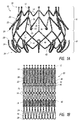
- Figure 1B illustrates the flat cut pattern of the frame shown in Figure 1A .
- the flat pattern can be cut from a metal tube and then the tube can be bent and expanded to the shape shown in Figure 1A .
- the frame 20 can further be expanded and/or compressed and/or otherwise worked to have the desired shape or shapes, such as for introduction and implantation.
- the frame when in an expanded configuration, such as in a fully expanded configuration, has a bulbous or slightly bulbous shape, with a middle portion being larger than the proximal 32 and distal 34 ends.
- the inside diameter of the both ends can be the same, or it can be bigger on one end than the other, while still having a middle portion larger than both the proximal and distal ends.
- the effective diameter of the distal frame end is smaller than the effective diameter of the middle portion.
- the bulbous shape of the frame can advantageously allow the frame to engage a native valve annulus or other body cavity, while spacing the inlet and outlet from the heart or vessel wall.
- the frame may not have a bulbous portion, and can have substantially the same outer dimension along its entire length, or it may have one end larger than the other end.
- the prosthesis 10 and frame 20 may be similar to the replacement heart valves and associated frames disclosed in U.S. Patent No. 8,403,983 and U.S. Publication Nos. 2010/0298931 , 2011/0313515 and 2012/0078353 the entireties of each of which are hereby incorporated by reference and made a part of this specification. This is inclusive of the entire disclosure and is not in any way limited to the disclosure of the replacement heart valves and associated frames.
- FIG. 1 illustrates the frame in an expanded configuration with a number of longitudinal struts 12 and undulating struts 14, with cells defined by the open spaces between the struts.
- the longitudinal struts may be arranged so that they are parallel or generally or substantially parallel to a longitudinal axis of the frame.
- the longitudinal axis of the frame may be defined as the central axis that extends through the center of the frame between the proximal 32 and distal 34 ends.
- Any number of configurations of struts can be used, such as the rings of undulating struts shown forming chevrons and diamonds, but also ovals, curves, and various other shapes.
- the illustrated embodiment includes two rings, or rows of chevrons shown in portion 16 and two rows of diamond-shaped cells shown in portion 18.
- the frame 20 has a non-foreshortening portion 16 and a foreshortening portion 18. These portions can be defined by the frame 20 and the positioning of various types of struts along the frame 20.
- the longitudinal struts 12 span the length of the non-foreshortening portion 16, while undulating struts 14 form the foreshortening portion 18.
- the struts 14 become more parallel with respect to the longitudinal axis of the frame, causing an outer diameter of the frame to decrease and the longitudinal length of the frame to increase in the foreshortening portion 18.
- the longitudinal length of the frame can decrease in the foreshortening portion 18. But, the frame length does not substantially change length in the non-foreshortening portion 16.
- Foreshortening of the frame 20 can be used to engage and secure the prosthesis to intralumenal tissue in a body cavity, for example tissue at or adjacent a native valve, such as a native valve annulus and/or leaflets.
- Opposing anchors 22, 24 can be constructed on the frame 20 so that portions of the anchors, such as tips or ends 26, 28, move closer together as the frame foreshortens. As one example, this can allow the anchors 22, 24 to grasp tissue on opposite sides of the native mitral annulus to thereby secure the prosthesis at the mitral valve.
- the anchors 22, 24 and anchor tips 26, 28 can be located anywhere along the frame 20 just so long as at least one of the anchors is either connected to the foreshortening portion 18 or the foreshortening portion is positioned between the anchors so that a portion of the anchors will be move closer together with expansion of the frame.
- the anchors 24 are connected to the foreshortening portion 18.
- the foreshortening portion can also be positioned anywhere along the frame, though it is shown towards the distal end 34.
- both of the anchor tips 26, 28 are located in the foreshortening portion 18.
- the foreshortening portion 18 may extend the entire length of the frame, such that there is no non-foreshortening portion 16.
- each of the anchors 22, 24 is positioned or extends generally radially outwardly from the frame 20 so that the anchor tips 26, 28 are generally spaced away or radially outward from the rest of the frame 20.
- the anchor tips may be located radially outward from the middle portion of the frame, with the tips 26 and 28 being axially spaced from one another.
- all or part of the structure connected to the anchor tip and extending radially from the frame, including one or more rings and/or struts can be considered part of the anchor.
- the anchors can include a base located on the anchor on a side opposite the tip. The base can be for example where the anchor begins to extend from or away from the frame 20.
- proximal anchors 22 are shown having first 36 and second 38 struts forming a chevron and connected to longitudinal struts 12 at a base of the anchor.
- the first and second struts of the anchor 22 are bent at the base so that the anchor 22 extends radially outwardly from the frame as it extends generally distally towards the tip 26.
- the first and second struts can be connected to each other at a radially outward location to form an outwardly extending loop, and in some embodiments, the first and second struts can be joined at a third strut 40 that continues to extend outwardly and/or generally distally.
- the third strut 40 is a short strut.
- the anchor also includes an eyelet 46.
- the eyelet is located at the distal end 26, though the eyelet can be positioned in other locations along the anchor 22.
- the tips 26 of the proximal anchors may extend distally and be parallel or substantially parallel with the longitudinal axis of the frame, or as illustrated in Figure 1A , the tips 26 may extend generally distally but still radially outwardly inclined or at an acute angle relative to the longitudinal axis of the frame.
- the distal anchors 24 are shown having looped ends 48.
- the looped ends can be larger near the tip to form a type of elongated teardrop.
- the tips 28 may be substantially flat.
- the looped end may assist the frame in not getting caught up on structures at or near the treatment location.
- each loop can be configured so that when the frame is deployed in-situ and expands, the movement of each loop from a delivered position to a deployed position can avoids getting caught on the papillary muscles.
- Each distal anchor 24 is connected to the frame at a base 42.
- the base of the distal anchor may be at a location where the corners of adjacent cells meet, such that the base is proximal to the distal end 34 of the frame.
- the base of the distal anchor may be at a distal most corner of a cell, which corresponds to a distal most point on the frame
- the distal anchors as illustrated extend from the base 42 generally distally before bending back around in an arcuate segment where the distal anchor extends generally proximally and radially outwardly from the frame.
- the anchors 24 may also generally distally and radially inwardly with respect to the frame such that the distal most point on the prosthesis has a smaller inside diameter than where the base 42 connects to the frame.
- the inside diameter at the distal most can be the same or substantially the same as the inside diameter of the proximal end, or may be smaller.
- the anchor as illustrated is bent around about 180 degrees so that the tip 28 extends in the opposite, proximal direction, which may be parallel or substantially parallel to the longitudinal axis of the frame.
- the distal anchors 24 are bent further inward such that the ends of the anchors point proximally and are generally parallel with the longitudinal axis of the frame.
- the tip 28 may extend generally proximally but still extend radially outwardly inclined or at an acute angle relative to the longitudinal axis of the frame
- each of the anchors can extend radially outwardly from the frame at an anchor base and terminate at an anchor tip.
- the anchors can be connected to the frame at one of many different locations including apices, junctions, other parts of struts, etc.
- the anchors can comprise first, second, third, or more spaced apart bending stages along the length of each anchor.
- the anchors can also extend either distally or proximally before and/or after one or more of the bending stages. A portion of the anchor may extend with the frame before or after any bending stages.
- FIG. 1A-B there are twelve distal anchors and twelve proximal anchors. In some embodiments there may be 6 anchors on one side and 12 on the other. Some embodiments may include different numbers of anchors. In addition, the distal and proximal anchors may be aligned so the tips point generally towards each other, or they may be spaced so that the tips point between two tips on the opposite side, as is illustrated in Figures 1A-B .
- the anchor tips 26 and 28 as described above advantageously provide atraumatic surfaces that may be used to grasp intralumenal tissue without causing unnecessary or undesired trauma to tissue.
- the proximal anchors tips 26 and distal anchor tips 28 may form flat, substantially flat, curved or other non-sharp surfaces to allow the tips to engage and/or grasp tissue, without necessarily piercing or puncturing through tissue.
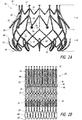
- Figures 2A-3B show prostheses similar to that of Figures 1A-B with two different styles of distal anchors 24.
- the looped end 48' of the distal anchor is generally more elliptical with a curved tip as compared to the elongated teardrop shape of looped end 48 of Figures 1A-B . Otherwise the shape is substantially the same.
- the distal anchors 24 are looped anchors rather than having looped ends.
- the looped anchor has a first base 42 and a second base 44 connected to the frame, wherein the first and second bases are at opposite corners of the same cell. Alternatively, the first and second bases may be located at the distal most corners of adjacent cells.
- the distal anchors 24 extends generally distally from the frame at the first base 42 but then is bent back around and begins to extend outwardly from the frame in a generally proximal direction. The distal anchor 24 then repeats this configuration in reverse towards the second base 44 such that the two sides of the looped anchor are mirror images of one another. It will be understood that the looped anchor can have other configurations and that it may not be symmetrical.
- the tips 28 of the distal anchors are circumferentially aligned with the tips 26 of the proximal anchors, though in other embodiments, the tips 28 of the distal anchors may be circumferentially staggered between the tips 26 of the proximal anchors.
- adjacent distal anchors 26 are spaced apart by one cell, though in other embodiments, adjacent distal anchors may be provided on adjacent cells.
- the illustrated looped distal anchor of Figures 3A-B is made up of the following segments.
- the first segment 50 extends generally longitudinally with the frame, extending distally or generally distally (e.g., slightly radially inward) with the frame.
- the strut is then bent so that a second segment 52 extends generally parallel with an adjacent undulating strut 14.
- the strut is then bent so that a third segment 54 begins to extend generally longitudinally and distally or generally distally, and then is bent back around to point in generally the opposite direction (e.g., in a proximal direction parallel or generally parallel with the longitudinal axis of the frame).
- the third segment 54 ends in the rounded tip 28 and then the anchor strut repeats to form the mirror image.
- the third segment 54 may first extend radially outward at an acute angle relative to the longitudinal axis before bending into a portion that extends parallel or substantially parallel to the longitudinal axis.
- the paired third segments 54 extend parallel or generally parallel with one another from the second segment to the tip, though they may also move slightly towards or away from each other in some embodiments.
- Figures 4A-B show a prosthesis similar to Figures 3A-B that also has looped distal anchors.
- the first segment 50 extends longitudinally in a distal direction from the frame and the strut is bent back on itself to point generally in the opposite (e.g., proximal) direction.
- the second segment is bent inward before extending parallel or generally parallel with its mirror image on the other side forming a nose and wing configuration similar to the shape of certain bicycle seats.
- the proximal anchors 22 also have an elongated third strut 40.
- the proximal anchor 22 is shown having first 36 and second 38 struts forming a chevron and connected to longitudinal struts 12 at a base of the anchor.
- the first and second struts of the anchor 22 are bent at the base so that the anchor 22 extends radially outwardly from the frame as it extends towards the tip 26.
- the first and second struts join at a third strut 40 that continues to extend outwardly and is then bent such that the tip points distally and extends in a manner parallel or generally parallel with the longitudinal axis of the frame.
- the proximal anchor may or may not include an eyelet 46 along its length.
- the distal tip of the proximal anchors may have an atraumatic surface, such as an enlarged circular or curved end as illustrated.
- the distal anchors 24 may have tips 28 that are positioned radially outward of the tips 26 of the proximal anchors 22.
- Other embodiments may have the tips 26 being positioned outward of the tips 28.
- Such configurations are also possible with the other frames and prostheses described elsewhere herein.
- Figure 5 illustrated an embodiment similar to the prosthesis of Figure 4B with twelve distal anchors instead of six. Because of this change, in one embodiment two anchors share the first segment 50 where the anchor base 42, 44 is connected to the frame. As illustrated, each of the proximal and distal anchors may be circumferentially aligned with each other, and each of the distal anchors corresponds to one of the cells
- a prosthesis can include one or more of a valve 60, a skirt 70 and a support band 80.
- the prosthesis can be a replacement heart valve similar to that and including features similar to those disclosed in U.S. Patent Appl. Nos. 13/165,721, filed June 21, 2011 , published as U.S. 2011/0313515 ; and 13/244,080, filed September 23, 2011 , published as 2012/0078353 .
- the entire contents of both applications are hereby incorporated by reference herein and made a part of this specification. This is inclusive of the entire disclosure and is not in any way limited to the disclosure of the replacement heart valve.
- the valve 60 can be a replacement heart valve which includes a plurality of valve leaflets 62.
- the plurality of valve leaflets 62 can function in a manner similar to the natural mitral valve, or to other valves in the vascular system.
- the plurality of valve leaflets 62 can open in a first position and then engage one another to close the valve in a second position.
- the plurality of valve leaflets 62 can be made to function as a one way valve such that flow in one direction opens the valve and flow in a second direction opposite the first direction closes the valve.
- the replacement heart valve 60 can be constructed so as to open naturally with the beating of the heart. For example, the plurality of valve leaflets 62 can open during diastole and close during systole.
- the leaflets 62 can be coupled to a skirt 70.
- the proximal ends of the leaflets 62 can be connected to a proximal end of the skirt 70.
- the skirt 70 can be used to at least partially control how fluid flows through and/or around the valve 60.
- the skirt 70 can surround at least a portion of the valve and be connected to the valve leaflets 62.
- the skirt 70 can form an inner wall connected to and positioned within the frame 20.
- the skirt 70 can also be made to move with the foreshortening portion 18 of the frame 20.
- the skirt 70 can extend the length of the frame 20 or it can extend along only part of the length of the frame 20.
- the ends of the heart valve 60 can coincide with ends of the skirt 70.
- one or more of the ends of the frame 20 can coincide with the ends of the skirt 70.
- the proximal end of the skirt 70 and heart valve 60 are sewn together.
- the skirt 70 can not only extend to the distal end of the frame 20 but can also extend to the outside of the frame and is shown wrapped around each of the distal anchors 24.
- skirt 70 may extend along the length of the leaflets 62, but is not connected to them. In the illustrated embodiments, the skirt 70 is attached to the frame 20 and the leaflets 62 are attached to the skirt 70.
- the skirt 70 can be constructed in multiple different ways.
- the skirt 70 can be made of knit polyester or another stretchable or flexible fabric.
- the skirt 70 is made from a material that is more flexible than the valve leaflet material.
- the distal and/or proximal end of the skirt 70 can be straight, curved, or have any other desired configuration.
- the skirt 70 is shown with undulations patterned to generally correspond to the undulations at the distal end 34 of the frame 20. It can be seen that the skirt 70 wraps around the struts at the distal end.
- the skirt 70 can be formed of one piece or multiple pieces.
- the skirt 70 attached to the valve 60 can be one piece and then each distal anchor can be covered by a separate piece of material of the skirt 70.
- Figure 6A This is illustrated in Figure 6A as one of the distal anchors on the back side remains uncovered.
- Figure 6C shows the distal anchors uncovered.
- the skirt 70 can also be employed.
- the anchors may remain uncovered, or only a portion may be covered.
- skirt 70 another embodiment of the skirt 70 is shown.
- the skirt rather than the skirt 70 corresponding to the undulations at the distal end 34 of the frame 20, the skirt extends past the frame and is then wrapped around it.
- the skirt 70 extends from the inside of the frame 20 to the outside of the frame.
- the skirt can extend completely around the frame for 1/4, 1/3, 1/2, or more of the length of the distal anchors.
- the skirt can also cover the distal anchors 24.
- the skirt is a one piece skirt, but it will be understood that the skirt can be made of multiple pieces.
- the skirt 70 and particularly portions that cover the distal anchors 24, can beneficially be used to help prevent leakage of blood flow around the heart valve.
- the skirt can encourage tissue in-growth between the skirt and the natural tissue. This may further help to prevent leakage of blood flow around the heart valve.
- the prosthesis 10 can also include a support band 80 as is shown in Figures 6A-7B .
- the support band 80 may be placed or positioned around or within the frame 20 at the proximal end 32.
- the support band 80 can be used to reinforce and/or constrain the frame 20.
- the support band 80 can help to control the expansion of the frame 20 from the compacted to the expanded state.
- the support band 80 can also be used to reduce the amount of motion that occurs at the proximal end 32 after the prosthesis 10 has been implanted at the mitral heart valve or other location.
- the support band 80 may comprise a polyester fabric band.
- the support band 80 may comprise a no-stretch or limited stretch material.
- the support band 80 is not made of an elastic material or a material known to have high elasticity.
- the support band 80 is made from a material that is less flexible than the valve skirt material and/or the valve leaflet material.
- the distal and proximal ends of the support band 80 can be straight, curved, undulating with the undulations of frame, or any other desired configuration.
- the support band 80 can be connected to the valve frame with a plurality of stitches, loops, knots, staples, or other types of connections.
- the frame 20 can be sandwiched between two sides or layers of the support band 80.
- the support band 80 is a single layer positioned within and attached to the frame 20 with a plurality of stitches around one or more of the longitudinal and/or undulating struts.
- the support band 80 can be attached to the proximal end of the valve skirt 40.
- Figures 8A-D show a prosthesis similar to that of Figures 4A-B with a different style and configuration of distal anchor 24.
- the distal anchors are shorter than and spaced radially inward from the distal anchors of Figures 4A-B .
- the distal anchors 24 are not positioned as far radially outward as the proximal anchors, and the tips 28 may be positioned radially inward of the tips 26.
- such a configuration may be advantageous in positioning and securing the prosthesis in a mitral valve or other body location.
- the distal anchors 24 may comprise loops as described above, having a curved or arcuate atraumatic tip to minimize damage to body tissue.
- Figures 9A-D show an embodiment of a prosthesis where the distal anchors do not comprise loops, but instead comprise single struts each extending distally from the corners where adjacent cells meet.
- these anchors may first extend distally or generally distally, and may further extend radially inward, before bending around to extend proximally or generally proximally, such as at an acute angle relative to the longitudinal axis of the frame.
- the tips 28 of the anchors may comprise an atraumatic surface, such as a flattened or curved enlarged tip. As illustrated, the tips 28 may be circumferentially staggered between tips 26 of the proximal anchors 22, as best shown in Figures 9C and 9D.
- Figures 9C-D also show the frame 20 having a valve 60 and skirt 70 attached as described above.
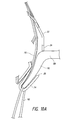
- any of the prostheses 10 described above may be deployed into a heart valve annulus, and positioned when compacted so that the anchor tips 26, 28 of the opposing anchors 22, 24 are disposed on opposite sides of the native annulus 88 as shown in Figures 10 and 10A .
- the opposing anchors are drawn closer together so as to grasp tissue on opposite sides of the native annulus 88 and securely hold the replacement heart valve 10 in position.
- the replacement heart valve 10 can be held securely in position without requiring a substantial radial force against the native annulus. Because the anchor tips are preferably atraumatic, the grasping or engaging of tissue by the prosthesis minimizes damage to the native tissue.
- the foreshortening portion 18 can be used to move the anchor tips 26, 28 closer together as the replacement heart valve 10 moves to the expanded position to thereby engage the native valve annulus.
- the prosthesis can be deployed into a heart valve or otherwise deployed in manners similar to those described with respect to a replacement heart valve in U.S. Publication No. 2010/0298931 and 2012/0078353 the entireties of each of which are hereby incorporated by reference and made a part of this specification. This is inclusive of the entire disclosure and is not in any way limited to the disclosure related to deployment of a replacement heart valve.
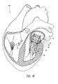
- FIGS 10 and 10A show a schematic representation of the replacement heart valve 10 installed in a human heart 84.
- the heart is shown in cross-section, and represents typical anatomy, including a left atrium 78 and left ventricle 86.
- the left atrium 78 and left ventricle 86 communicate with one another through a mitral annulus 88.
- Also shown schematically is a native anterior mitral leaflet 90 having chordae tendineae 92 that connect a downstream end of the anterior mitral leaflet 90 and to the left ventricle 86.
- a method is provided of delivering a replacement valve to a native mitral valve and atraumatically securing the replacement valve relative to the native mitral valve annulus 88.
- the replacement valve can be mounted on a delivery device and delivered to the native mitral valve annulus while the replacement valve is in a radially compacted state.
- the replacement valve may be positioned so that the ends or tips of the distal anchors are on a ventricular side of the native leaflets 90 beyond a location where chordae tendineae 92 connect to free ends of the native leaflets. At least a portion of the replacement valve can be released from the delivery device to thereby expand the distal anchors radially outwardly. At this time the distal anchors may extend between at least some of the chordae.
- the distal anchors (along with the frame) can be moved toward the ventricular side of the native valve annulus with the distal anchors extending between at least some of the chordae tendineae to provide tension on the chordae tendineae.
- the replacement valve With tension provided on the chordae tendineae, the replacement valve can be further released from the delivery device to thereby expand the proximal anchors radially outwardly.
- the proximal anchors upon further release of the replacement valve from the delivery device can move into engagement with tissue on an atrial side of the native valve annulus, such as with the atrial side of the native valve annulus.
- the method just described may utilize any of the prostheses herein described, but may be particularly suitable for the prosthesis of Figures 8A-8D where the ends of the distal anchors are not positioned as far out radially as the ends of the proximal anchors when the frame is expanded.
- the distal anchors may have a suitable length for extending between and providing tension on the chordae tendineae, but need not and may in some embodiments not engage tissue with the tips 28.
- the some or all of the distal anchors remain spaced from tissue on the ventricular side of the native valve annulus after delivery and expansion.
- the interaction between the distal anchors and the chordae tendineae may therefore be sufficient to secure the distal end of the prosthesis, while the engagement of the proximal anchors with tissue on the atrial side of the native valve annulus will help further secure and orient the prosthesis
- the distal anchors may comprise loops, such as any of the looped structures previously described.
- the distal anchors may also be covered with a resilient material such as described above for the skirt 70 that promotes tissue growth with adjacent body tissue. Such material may also be useful to prevent paravalvular leakage.
- the atraumatic distal anchors may advantageously prevent snagging of the prosthesis on internal structures, such as the papillary muscles.
Landscapes
- Health & Medical Sciences (AREA)
- Engineering & Computer Science (AREA)
- Biomedical Technology (AREA)
- Cardiology (AREA)
- Oral & Maxillofacial Surgery (AREA)
- Transplantation (AREA)
- Heart & Thoracic Surgery (AREA)
- Vascular Medicine (AREA)
- Life Sciences & Earth Sciences (AREA)
- Animal Behavior & Ethology (AREA)
- General Health & Medical Sciences (AREA)
- Public Health (AREA)
- Veterinary Medicine (AREA)
- Prostheses (AREA)
Abstract
Description
- Certain embodiments disclosed herein relate generally to prostheses for implantation within a lumen or body cavity. In particular, certain embodiments relate to expandable prostheses such as replacement heart valves, such as for the mitral valve, that are configured to atraumatically grasp intralumenal tissue.
- Human heart valves, which include the aortic, pulmonary, mitral and tricuspid valves, function essentially as one-way valves operating in synchronization with the pumping heart. The valves allow blood to flow downstream, but block blood from flowing upstream. Diseased heart valves exhibit impairments such as narrowing of the valve or regurgitation, which inhibit the valves' ability to control blood flow. Such impairments reduce the heart's blood-pumping efficiency and can be a debilitating and life threatening condition. For example, valve insufficiency can lead to conditions such as heart hypertrophy and dilation of the ventricle. Thus, extensive efforts have been made to develop methods and apparatuses to repair or replace impaired heart valves.
- Prostheses exist to correct problems associated with impaired heart valves. For example, mechanical and tissue-based heart valve prostheses can be used to replace impaired native heart valves. More recently, substantial effort has been dedicated to developing replacement heart valves, particularly tissue-based replacement heart valves that can be delivered with less trauma to the patient than through open heart surgery. Replacement valves are being designed to be delivered through minimally invasive procedures and even percutaneous procedures. Such replacement valves often include a tissue-based valve body that is connected to an expandable frame that is then delivered to the native valve's annulus.
- Development of prostheses including but not limited to replacement heart valves that can be compacted for delivery and then controllably expanded for controlled placement has proven to be particularly challenging. An additional challenge relates to the ability of such prostheses to be secured relative to intralumenal tissue, e.g., tissue within any body lumen or cavity, in an atraumatic manner. Further challenges arise when trying to controllably deliver and secure such prostheses in a location such as at a native mitral valve.
- Embodiments of the present disclosure are directed to a prosthesis, such as but not limited to a replacement heart valve. Further embodiments are directed to methods of delivering a prosthesis into a body cavity and/or securing a prosthesis to intralumenal tissue. In some embodiments, a replacement heart valve and methods for delivering a replacement heart valve to a native heart valve, such as a mitral valve, are provided.
- In some embodiments a prosthesis can comprise an expandable frame, and a plurality of anchors, for example a plurality of distal anchors and a plurality of proximal anchors. The anchors can extend outwardly from the frame. The frame can be configured to radially expand and contract for deployment within the body cavity. In some embodiments, when the frame is in an expanded configuration, the frame can have a larger cross-sectional dimension in a middle portion of the frame and a smaller cross-sectional dimension in a proximal portion and a distal portion of the frame, wherein the middle portion is between the proximal and distal portions. In some embodiments, at least some of the anchors comprise a loop that forms an atraumatic end of a corresponding anchor.
- In some embodiments, a prosthesis can be configured to atraumatically grasp intralumenal tissue when deployed within a body cavity. The prosthesis can comprise an expandable frame comprising a proximal end and a distal end and having a longitudinal axis extending between the proximal end and the distal end. The frame can be configured to radially expand and contract for deployment within the body cavity, wherein when the frame is in an expanded configuration, the frame has a larger cross-sectional dimension in a middle portion of the frame and a smaller cross-sectional dimension in a proximal portion and a distal portion of the frame, wherein the middle portion is between the proximal and distal portions. The prosthesis can also include a plurality of generally distally extending anchors extending from the proximal portion of the frame and configured so that when the frame is in an expanded configuration each distally extending anchor has an end positioned radially outward from the middle portion of the frame. Alternatively or in addition, the prosthesis can include a plurality of generally proximally extending anchors extending from the distal portion of the frame and configured so that when the frame is in an expanded configuration each proximally extending anchor has an end positioned radially outward form the middle portion of the frame and axially spaced from the ends of the distally extending anchors. At least some of the anchors can comprise a loop that forms an atraumatic end of the anchor. The frame can be configured such that radial expansion of the frame causes the ends of the plurality of distally extending anchors and the ends of the plurality of proximally extending anchors to draw closer together.
- A prosthesis according to certain embodiments can be configured to atraumatically grasp intralumenal tissue when deployed within a body cavity. The prosthesis can comprise an expandable frame. A plurality of proximal anchors may be connected to the frame so that when the frame is in an expanded configuration an end of each proximal anchor is positioned radially outward from the frame and extends generally distally. Alternatively or in addition, a plurality of distal anchors may be connected to the frame so that when the frame is in an expanded configuration an end of each distal anchor is positioned radially outward from the frame and extends generally proximally. The ends of the distal anchors are axially spaced from the ends of the proximal anchors when the frame is in an expanded configuration. In some embodiments, at least some of the anchors can comprise a looped end.
- Alternatively, or in addition, in some embodiments, at least some of the anchors can comprise a loop. Each loop of these later embodiments can comprise first through fourth segments and an arcuate segment. The first and second segments can both extend in a first generally axial direction away from the frame. The third and fourth segments can extend radially outward from the frame in a second direction generally opposite the first direction, the third segment connected to the first segment and the fourth segment connected to the second segment. The arcuate segment can connect the third segment and the fourth segment that forms an atraumatic end of a corresponding anchor. In some embodiments, the frame is configured such that radial expansion of the frame causes the ends of the plurality of proximal anchors and the ends of the plurality of distal anchors to draw closer together.
- In some embodiments, a prosthesis can be configured to atraumatically grasp intralumenal tissue when deployed within a body cavity. The prosthesis can comprise an expandable frame and a plurality of anchors, for example a plurality of proximal anchors, and a plurality of distal anchors. The expandable frame can comprise a proximal end and a distal end and having a longitudinal axis extending between the proximal end and the distal end, the frame configured to radially expand and contract for deployment within the body cavity. The plurality of proximal anchors can each connect to the frame so that when the frame is in an expanded configuration an end of each proximal anchor is positioned radially outward from the frame and extends generally distally. The plurality of distal anchors can each connect to the frame so that when the frame is in an expanded configuration an end of each distal anchor is positioned radially outward from the frame and extends generally proximally, wherein the ends of the distal anchors are axially spaced from the ends of the proximal anchors when the frame is in an expanded configuration. At least some of the anchors can comprise a loop. Each of the anchors that comprises a loop can comprise at least a first segment extending in a first generally axial direction away from the frame, and a second segment and a third segment extending radially outward from the frame in a second direction generally opposite the first direction and coming together in an atraumatic end. The frame can be configured such that radial expansion of the frame causes the ends of the plurality of proximal anchors and the ends of the plurality of distal anchors to draw closer together.
- According to some embodiments a prosthesis can be configured to atraumatically grasp intralumenal tissue when deployed within a body cavity. The prosthesis can comprise an expandable frame comprising a proximal end and a distal end and having a longitudinal axis extending between the proximal end and the distal end, the frame configured to radially expand and contract for deployment within the body cavity. A plurality of proximal anchors may be connected to the frame so that when the frame is in an expanded configuration an end of each proximal anchor is positioned radially outward from the frame and extends generally distally. Alternatively or in addition, a plurality of distal anchors may be connected to the frame so that when the frame is in an expanded configuration an end of each distal anchor is positioned radially outward from the frame and extends generally proximally. The ends of the distal anchors are axially spaced from the ends of the proximal anchors when the frame is in an expanded configuration. At least some of the anchors can comprise a loop and each loop can comprise first through fourth segments and an arcuate segment. The first and second segments can both extend in a first generally axial direction away from the frame. The third and fourth segments can extend radially outward from the frame in a second direction generally opposite the first direction, the third segment connected to the first segment and the fourth segment connected to the second segment. The arcuate segment can connect the third segment and the fourth segment that forms an atraumatic end of a corresponding anchor. The frame can be configured such that radial expansion of the frame causes the ends of the plurality of proximal anchors and the ends of the plurality of distal anchors to draw closer together.
- Methods of delivering a prosthesis and/or securing the prosthesis to intralumenal tissue, and use of a prosthesis to secure to intraluminal tissue, for example as a replacement heart valve to secure to a mitral valve or other annulus, are also provided. In one embodiment, a method of delivering a replacement valve to a native mitral valve can comprise one or more of the following steps. Delivering a replacement valve mounted on a delivery device to the native mitral valve annulus while the replacement valve is in a radially compacted state, the replacement valve comprising a radially expandable frame comprising a proximal end, a distal end, a plurality of distal anchors extending generally proximally from the frame, and a plurality of proximal anchors extending generally distally from the frame. Positioning the replacement valve so that ends of the distal anchors are on a ventricular side of the native leaflets beyond a location where chordae tendineae connect to free ends of the native leaflets. Releasing at least a portion of the replacement valve from the delivery device to thereby expand the distal anchors radially outwardly to a first radial dimension. Moving the ends of the distal anchors toward the ventricular side of the native valve annulus with the distal anchors extending between at least some of the chordae tendineae to provide tension on the chordae tendineae. Further releasing the replacement valve from the delivery device to thereby expand the proximal anchors radially outwardly to a second radial dimension greater than the first radial dimension, wherein the proximal anchors upon further release of the replacement valve from the delivery device move into engagement with tissue on an atrial side of the native valve annulus while the distal anchors provide tension on the chordae tendineae.
- Further embodiments contemplated by the present disclosure are summarized in the following numbered paragraphs.
- 1. A prosthesis configured to atraumatically engage intralumenal tissue when deployed within a body cavity, the prosthesis comprising:
- an expandable frame comprising a proximal end and a distal end and having a longitudinal axis extending between the proximal end and the distal end, the frame configured to radially expand and contract for deployment within the body cavity; and
- a plurality of distal anchors each connected to the frame at a base and having a looped atraumatic end;
- wherein when the frame is in an expanded configuration each of the plurality of distal anchors extends from the base generally distally before extending generally proximally and radially outwardly from the frame.
- 2. The prosthesis of Embodiment 1, wherein the frame comprises a plurality of cells formed by interconnected struts.
- 3. The prosthesis of Embodiment 2, wherein the base of each of the plurality of distal anchors is at a location where corners of two adjacent cells meet.
- 4. The prosthesis of any one of Embodiment 2-3, wherein the base of each of the plurality of distal anchors is at a distalmost corner of a cell.
- 5. The prosthesis of any one of Embodiment 2-4, wherein adjacent looped ends of the plurality of distal anchors are spaced apart by at least one cell.
- 6. The prosthesis of any one of Embodiment 2-5, wherein when the frame is in an expanded configuration, a width of each of the plurality of distal anchors as defined circumferentially around the longitudinal axis over the entire length of the distal anchor from the base to the looped atraumatic end is less than the width of one cell.
- 7. The prosthesis of any one of Embodiments 1-6, wherein the looped atraumatic end of each distal anchor is circumferentially aligned with the base where the distal anchor connects to the frame so that the looped atraumatic end and the base are both located within a common plane that is parallel to and intersects the longitudinal axis.
- 8. The prosthesis of any one of Embodiments 1-7, wherein each of the plurality of distal anchors is connected to the frame with a single strut.
- 9. The prosthesis of any one of Embodiments 1-8, wherein when the frame is in an expanded configuration, the looped atraumatic end of each of the plurality of distal anchors is proximal to the base where the distal anchor connects to the frame.
- 10. The prosthesis of any one of Embodiments 1-9, wherein the ends of the plurality of distal anchors are inclined relative to the longitudinal axis of the frame.
- 11. The prosthesis of any one of Embodiments 1-10, wherein the ends of the plurality of distal anchors are substantially parallel to the longitudinal axis of the frame.
- 12. The prosthesis of any one of Embodiments 1-11, further comprising a plurality of proximal anchors each connected to the frame, wherein the frame is configured such that radial expansion of the frame causes ends of the plurality of proximal anchors and the ends of the plurality of distal anchors to draw closer together.
- 13. The prosthesis of
Embodiment 12, wherein when the frame is in an expanded configuration an end of each of the plurality of proximal anchors is positioned radially outward from the frame and extends distally. - 14. The prosthesis of
Embodiment 12 or 13, wherein the ends of the plurality of distal anchors are axially spaced from the ends of the proximal anchors when the frame is in an expanded configuration. - 15. The prosthesis of any one of Embodiments 12-14, wherein the ends of the plurality of proximal anchors are positioned radially outward from the ends of the plurality of distal anchors when the frame is in an expanded configuration.
- 16. The prosthesis of any one of Embodiments 12-14, wherein the ends of the plurality of distal anchors are positioned radially outward from the ends of the plurality proximal anchors when the frame is in an expanded configuration.
- 17. The prosthesis of any one of Embodiments 12-16, wherein the ends of the plurality of distal anchors are not circumferentially aligned with the ends of the plurality proximal anchors when the frame is in an expanded configuration.
- 18. The prosthesis of any one of Embodiments 12-17, wherein the plurality of proximal anchors each comprises a single arm that terminates in an atraumatic tip.
- 19. The prosthesis of any one of Embodiments 12-18, wherein the plurality of proximal anchors are connected to a non-foreshortening portion of the frame, and the plurality of distal anchors are connected to a foreshortening portion of the frame.
- 20. The prosthesis of any one of Embodiments 1-19, further comprising a valve body attached to the frame.
- 21. The prosthesis of any one of Embodiments 1-20, further comprising a layer of resilient material covering each of the looped ends to facilitate in-growth of adjacent tissue when the prosthesis is deployed within a body cavity.
- 22. The prosthesis of any one of Embodiments 1-21, wherein when the frame is in an expanded configuration, the frame has a larger cross-sectional dimension in a middle portion of the frame and a smaller cross-sectional dimension in a proximal portion and a distal portion of the frame, wherein the middle portion is between the proximal and distal portions.
- 23. The prosthesis of
Embodiment 22, wherein the plurality of distal anchors extend from the distal portion of the frame and are configured so that when the frame is in an expanded configuration, each distal anchor of the plurality of distal anchors has an end positioned radially outward from the middle portion of the frame. - 24. The prosthesis of
Embodiment 22 or 23, wherein the proximal end and the distal end have the same or substantially the same cross-sectional dimension. - 25. A prosthesis configured to atraumatically grasp intralumenal tissue when deployed within a body cavity, the prosthesis comprising:
- an expandable frame comprising a proximal end and a distal end and having a longitudinal axis extending between the proximal end and the distal end, the frame configured to radially expand and contract for deployment within the body cavity, wherein when the frame is in an expanded configuration, the frame has a larger cross-sectional dimension in a middle portion of the frame and a smaller cross-sectional dimension in a proximal portion and a distal portion of the frame, wherein the middle portion is between the proximal and distal portions;
- a plurality of distally extending anchors extending from the proximal portion of the frame and configured so that when the frame is in an expanded configuration each distally extending anchor has an end positioned radially outward from the middle portion of the frame;
- a plurality of proximally extending anchors extending from the distal portion of the frame and configured so that when the frame is in an expanded configuration each proximally extending anchor has an end positioned radially outward form the middle portion of the frame and axially spaced from the ends of the distally extending anchors;
- wherein at least some of the anchors comprise a loop that forms an atraumatic end of a corresponding anchor;
- wherein the frame is configured such that radial expansion of the frame causes the ends of the plurality of distally extending anchors and the ends of the plurality of proximally extending anchors to draw closer together.
- 26. The prosthesis of Embodiment 25, wherein the plurality of proximally extending anchors each comprises a loop that forms an atraumatic end of each of the proximally extending anchors.
- 27. The prosthesis of
Embodiment 25 or 26, wherein the plurality of distally extending anchors each comprises a single arm that terminates in an atraumatic tip. - 28. The prosthesis of any one of Embodiments 25-27, wherein the ends of the proximally extending anchors are circumferentially aligned with ends of the distally extending anchors.
- 29. The prosthesis of any one of Embodiments 25-28, wherein the ends of the distally extending anchors are parallel with the longitudinal axis of the frame.
- 30. The prosthesis of any one of Embodiments 25-29, wherein the ends of the proximally extending anchors are inclined relative to the longitudinal axis of the frame.
- 31. The prosthesis of any one of Embodiments 25-30, wherein the ends of the proximally extending anchors are positioned radially outward from the ends of the distally extending anchors when the frame is in an expanded configuration.
- 32. The prosthesis of any one of Embodiments 25-31, wherein the ends of the distally extending anchors are positioned radially outward from the ends of the proximally extending anchors when the frame is in an expanded configuration.
- 33. The prosthesis of any one of Embodiments 25-32, wherein the proximal end and the distal end have same cross-sectional dimension.
- 34. The prosthesis of any one of Embodiments 25-33, further comprising a valve body attached to the frame.
- 35. The prosthesis of any one of Embodiments 25-34, further comprising a layer of resilient material covering at least some of the loops to facilitate in-growth of adjacent tissue when the prosthesis is deployed within a body cavity.
- 36. A prosthesis configured to atraumatically grasp intralumenal tissue when deployed within a body cavity, the prosthesis comprising:
- an expandable frame comprising a proximal end and a distal end and having a longitudinal axis extending between the proximal end and the distal end, the frame configured to radially expand and contract for deployment within the body cavity;
- a plurality of proximal anchors each connected to the frame so that when the frame is in an expanded configuration an end of each proximal anchor is positioned radially outward from the frame and extends distally;
- a plurality of distal anchors each connected to the frame so that when the frame is in an expanded configuration an end of each distal anchor is positioned radially outward from the frame and extends proximally, wherein the ends of the distal anchors are axially spaced from the ends of the proximal anchors when the frame is in an expanded configuration;
- wherein at least some of the anchors comprise a loop, and each of the anchors that comprises a loop comprises:
- at least a first segment extending in a first generally axial direction away from the frame; and
- a second segment and a third segment extending radially outward from the frame in a second direction generally opposite the first direction and coming together in an atraumatic end;
- wherein the frame is configured such that radial expansion of the frame causes the ends of the plurality of proximal anchors and the ends of the plurality of distal anchors to draw closer together.
- 37. The prosthesis of
Embodiment 36, wherein the at least a first segment extending in a first generally axially direction away from the frame comprises two spaced-apart segments connected to the second and third segments, respectively. - 38. The prosthesis of
Embodiment 36 or 37, wherein the second and third segments come together in an arcuate portion. - 39. The prosthesis of any one of Embodiments 36-38, wherein at least some of the plurality of distal anchors comprises a loop.
- 40. The prosthesis of any one of Embodiments 36-39, wherein the second and third segments have portions that are substantially parallel to each other.
- 41. The prosthesis of any one of Embodiments 36-40, wherein the frame comprises a plurality of cells formed by interconnected struts.
- 42. The prosthesis of Embodiment 41, wherein the first segment extends in a first generally axially direction away from the frame from a location where corners of two adjacent cells meet.
- 43. The prosthesis of
Embodiments 41 or 42, wherein the first segment comprises two spaced-apart portions extending from locations on opposite sides of a cell. - 44. The prosthesis of any one of Embodiments 41-43, wherein adjacent loops are spaced apart by at least one cell.
- 45. The prosthesis of any one of Embodiments 36-44, wherein the ends of the distal anchors are generally inclined relative to the longitudinal axis of the frame.
- 46. The prosthesis of any one of Embodiments 36-45, wherein the ends of the proximal anchors are positioned radially outward from the ends of the distal anchors when the frame is in an expanded configuration.
- 47. The prosthesis of any one of Embodiments 36-46, further comprising a valve body attached to the frame.
- 48. The prosthesis of any one of Embodiments 36-47, further comprising a layer of resilient material covering each of the loops to facilitate in-growth of adjacent tissue when the prosthesis is deployed within a body cavity.
- 49. A replacement valve for use at a native mitral valve and suitable for atraumatically securing the replacement valve relative to the native mitral valve annulus, wherein the replacement valve comprises the prosthesis of any one of Embodiments 1-48.
- These and other features, aspects and advantages are described below with reference to the drawings, which are intended to illustrate but not to limit the invention. In the drawings, like reference characters denote corresponding features consistently throughout similar embodiments.
-
Figure 1A is a side view of an embodiment of a prosthesis. -
Figure 1B is a flat pattern view of the prosthesis ofFigure 1A . -
Figure 2A is a side view of an embodiment of a prosthesis. -
Figure 2B is a flat pattern view of the prosthesis ofFigure 2A . -
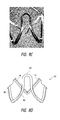
Figure 3A is a side view of an embodiment of a prosthesis. -
Figure 3B is a flat pattern view of the prosthesis ofFigure 3A . -
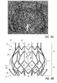
Figure 4A is a side view of an embodiment of a prosthesis. -
Figure 4B is a side view of the prosthesis ofFigure 4A . -
Figure 5 is a side view of an embodiment of a prosthesis. -
Figure 6A is a side view of an embodiment of a prosthesis configured as a replacement heart valve. -
Figure 6B is a side view of the prosthesis ofFigure 6A . -
Figure 6C is a bottom view of a prosthesis similar to the embodiment ofFigure 6A . -
Figure 6D is a bottom view of the prosthesis ofFigure 6B . -
Figure 7A is a side view of an embodiment of a prosthesis configured as a replacement heart valve. -
Figure 7B is a side view of the prosthesis ofFigure 7A . -
Figure 8A is a side view of an embodiment of a prosthesis. -
Figure 8B is a side view of the prosthesis ofFigure 8A . -
Figure 8C is a detail view of a portion of the prosthesis ofFigure 8A . -
Figure 8D is a detail view of a portion of the prosthesis ofFigure 8A . -
Figure 9A is a side view of an embodiment of a prosthesis. -
Figure 9B is a side view of the prosthesis ofFigure 9A . -
Figure 9C is a bottom view of the prosthesis ofFigure 9A , configured as a replacement heart valve. -
Figure 9D is a bottom view of the prosthesis ofFigure 9A , configured as a replacement heart valve. -
Figure 10 is a schematic representation of a prosthesis positioned within the heart. -
Figure 10A is a detail schematic representation of the prosthesis positioned within the heart ofFigure 10 . - The present specification and drawings provide aspects and features of the disclosure in the context of several embodiments of prostheses, replacement heart valves, delivery devices and methods that are configured for use in the vasculature of a patient, such as for replacement of natural heart valves in a patient. These embodiments may be discussed in connection with replacing specific valves such as the patient's aortic or mitral valve. However, it is to be understood that the features and concepts discussed herein can be applied to products other than heart valve implants. For example, the controlled positioning, deployment, and securing features described herein can be applied to medical implants, for example other types of expandable prostheses, for use elsewhere in the body, such as within a vein, or the like. In addition, particular features of a valve, delivery device, etc. should not be taken as limiting, and features of any one embodiment discussed herein can be combined with features of other embodiments as desired and when appropriate.
- With initial reference to
Figure 1A , an embodiment of aprosthesis 10 is shown. The illustratedprosthesis 10 includes aframe 20 that may be self-expanding or balloon expandable. The prosthesis may further include a replacement valve that can be designed to replace a damaged or diseased native heart valve such as a mitral valve. The replacement valve is not shown in this embodiment as to more clearly illustrate features of theframe 20, though it will be understood that a replacement valve is not required as part of the prosthesis. In addition, it will be understood that only a front portion of theframe 20 is shown for further ease of illustration. - The
frame 20 can be made of many different materials, but is preferably made from metal. In some embodiments, theframe 20 can be made from a shape memory material, such as nitinol. A wire frame or a metal tube can be used to make the frame. The wire frame of a metal tube can be cut or etched to remove all but the desired metal skeleton. In some embodiments a metal tube is laser cut in a repeating pattern to form the frame.Figure 1B illustrates the flat cut pattern of the frame shown inFigure 1A . The flat pattern can be cut from a metal tube and then the tube can be bent and expanded to the shape shown inFigure 1A . Theframe 20 can further be expanded and/or compressed and/or otherwise worked to have the desired shape or shapes, such as for introduction and implantation. - As shown, the frame when in an expanded configuration, such as in a fully expanded configuration, has a bulbous or slightly bulbous shape, with a middle portion being larger than the proximal 32 and distal 34 ends. In some embodiments, the inside diameter of the both ends can be the same, or it can be bigger on one end than the other, while still having a middle portion larger than both the proximal and distal ends. In some embodiments, the effective diameter of the distal frame end is smaller than the effective diameter of the middle portion. The bulbous shape of the frame can advantageously allow the frame to engage a native valve annulus or other body cavity, while spacing the inlet and outlet from the heart or vessel wall. This can help reduce undesired contact between the prosthesis and the heart or vessel, such as the ventricular wall of the heart. In other embodiments, the frame may not have a bulbous portion, and can have substantially the same outer dimension along its entire length, or it may have one end larger than the other end. The
prosthesis 10 andframe 20 may be similar to the replacement heart valves and associated frames disclosed inU.S. Patent No. 8,403,983 andU.S. Publication Nos. 2010/0298931 ,2011/0313515 and2012/0078353 the entireties of each of which are hereby incorporated by reference and made a part of this specification. This is inclusive of the entire disclosure and is not in any way limited to the disclosure of the replacement heart valves and associated frames. - A number of struts collectively make up the
frame 20.Figure 1 illustrates the frame in an expanded configuration with a number oflongitudinal struts 12 and undulating struts 14, with cells defined by the open spaces between the struts. The longitudinal struts may be arranged so that they are parallel or generally or substantially parallel to a longitudinal axis of the frame. The longitudinal axis of the frame may be defined as the central axis that extends through the center of the frame between the proximal 32 and distal 34 ends. Any number of configurations of struts can be used, such as the rings of undulating struts shown forming chevrons and diamonds, but also ovals, curves, and various other shapes. The illustrated embodiment includes two rings, or rows of chevrons shown inportion 16 and two rows of diamond-shaped cells shown inportion 18. - The
frame 20 has anon-foreshortening portion 16 and aforeshortening portion 18. These portions can be defined by theframe 20 and the positioning of various types of struts along theframe 20. InFigure 1 it can be seen that thelongitudinal struts 12 span the length of thenon-foreshortening portion 16, while undulatingstruts 14 form theforeshortening portion 18. When the frame is radially collapsed or compacted, thestruts 14 become more parallel with respect to the longitudinal axis of the frame, causing an outer diameter of the frame to decrease and the longitudinal length of the frame to increase in theforeshortening portion 18. As the frame moves from a compacted position to an expanded position, the longitudinal length of the frame can decrease in theforeshortening portion 18. But, the frame length does not substantially change length in thenon-foreshortening portion 16. - Foreshortening of the
frame 20 can be used to engage and secure the prosthesis to intralumenal tissue in a body cavity, for example tissue at or adjacent a native valve, such as a native valve annulus and/or leaflets. Opposinganchors frame 20 so that portions of the anchors, such as tips or ends 26, 28, move closer together as the frame foreshortens. As one example, this can allow theanchors - The
anchors anchor tips frame 20 just so long as at least one of the anchors is either connected to theforeshortening portion 18 or the foreshortening portion is positioned between the anchors so that a portion of the anchors will be move closer together with expansion of the frame. As shown, theanchors 24 are connected to theforeshortening portion 18. The foreshortening portion can also be positioned anywhere along the frame, though it is shown towards thedistal end 34. In some embodiments, both of theanchor tips foreshortening portion 18. In some embodiments, the foreshorteningportion 18 may extend the entire length of the frame, such that there is nonon-foreshortening portion 16. - Preferably, each of the
anchors frame 20 so that theanchor tips frame 20. For example, the anchor tips may be located radially outward from the middle portion of the frame, with thetips frame 20. - For example,
proximal anchors 22 are shown having first 36 and second 38 struts forming a chevron and connected tolongitudinal struts 12 at a base of the anchor. The first and second struts of theanchor 22 are bent at the base so that theanchor 22 extends radially outwardly from the frame as it extends generally distally towards thetip 26. The first and second struts can be connected to each other at a radially outward location to form an outwardly extending loop, and in some embodiments, the first and second struts can be joined at athird strut 40 that continues to extend outwardly and/or generally distally. Here thethird strut 40 is a short strut. The anchor also includes aneyelet 46. As illustrated, the eyelet is located at thedistal end 26, though the eyelet can be positioned in other locations along theanchor 22. Thetips 26 of the proximal anchors may extend distally and be parallel or substantially parallel with the longitudinal axis of the frame, or as illustrated inFigure 1A , thetips 26 may extend generally distally but still radially outwardly inclined or at an acute angle relative to the longitudinal axis of the frame. - As another example, the
distal anchors 24 are shown having looped ends 48. The looped ends can be larger near the tip to form a type of elongated teardrop. In addition, thetips 28 may be substantially flat. The looped end may assist the frame in not getting caught up on structures at or near the treatment location. For example, each loop can be configured so that when the frame is deployed in-situ and expands, the movement of each loop from a delivered position to a deployed position can avoids getting caught on the papillary muscles. - Each
distal anchor 24 is connected to the frame at abase 42. As illustrated inFigure 1A , the base of the distal anchor may be at a location where the corners of adjacent cells meet, such that the base is proximal to thedistal end 34 of the frame. In other embodiments, the base of the distal anchor may be at a distal most corner of a cell, which corresponds to a distal most point on the frame The distal anchors as illustrated extend from the base 42 generally distally before bending back around in an arcuate segment where the distal anchor extends generally proximally and radially outwardly from the frame. As shown, theanchors 24 may also generally distally and radially inwardly with respect to the frame such that the distal most point on the prosthesis has a smaller inside diameter than where thebase 42 connects to the frame. The inside diameter at the distal most can be the same or substantially the same as the inside diameter of the proximal end, or may be smaller. The anchor as illustrated is bent around about 180 degrees so that thetip 28 extends in the opposite, proximal direction, which may be parallel or substantially parallel to the longitudinal axis of the frame. For example, inFigure 1A it can be seen that thedistal anchors 24 are bent further inward such that the ends of the anchors point proximally and are generally parallel with the longitudinal axis of the frame. Alternatively, thetip 28 may extend generally proximally but still extend radially outwardly inclined or at an acute angle relative to the longitudinal axis of the frame - It will be understood that the anchors can have various other configurations, including the various embodiments that follow. In some embodiments, each of the anchors can extend radially outwardly from the frame at an anchor base and terminate at an anchor tip. The anchors can be connected to the frame at one of many different locations including apices, junctions, other parts of struts, etc. The anchors can comprise first, second, third, or more spaced apart bending stages along the length of each anchor. The anchors can also extend either distally or proximally before and/or after one or more of the bending stages. A portion of the anchor may extend with the frame before or after any bending stages.
- In the illustrated embodiment of
Figure 1A-B there are twelve distal anchors and twelve proximal anchors. In some embodiments there may be 6 anchors on one side and 12 on the other. Some embodiments may include different numbers of anchors. In addition, the distal and proximal anchors may be aligned so the tips point generally towards each other, or they may be spaced so that the tips point between two tips on the opposite side, as is illustrated inFigures 1A-B . - The
anchor tips proximal anchors tips 26 anddistal anchor tips 28 may form flat, substantially flat, curved or other non-sharp surfaces to allow the tips to engage and/or grasp tissue, without necessarily piercing or puncturing through tissue. -
Figures 2A-3B show prostheses similar to that ofFigures 1A-B with two different styles ofdistal anchors 24. InFigures 2A-B , the looped end 48' of the distal anchor is generally more elliptical with a curved tip as compared to the elongated teardrop shape of loopedend 48 ofFigures 1A-B . Otherwise the shape is substantially the same. - In
Figures 3A-B , thedistal anchors 24 are looped anchors rather than having looped ends. The looped anchor has afirst base 42 and asecond base 44 connected to the frame, wherein the first and second bases are at opposite corners of the same cell. Alternatively, the first and second bases may be located at the distal most corners of adjacent cells. The distal anchors 24 extends generally distally from the frame at thefirst base 42 but then is bent back around and begins to extend outwardly from the frame in a generally proximal direction. Thedistal anchor 24 then repeats this configuration in reverse towards thesecond base 44 such that the two sides of the looped anchor are mirror images of one another. It will be understood that the looped anchor can have other configurations and that it may not be symmetrical. - As illustrated in
Figure 3A , thetips 28 of the distal anchors are circumferentially aligned with thetips 26 of the proximal anchors, though in other embodiments, thetips 28 of the distal anchors may be circumferentially staggered between thetips 26 of the proximal anchors. In the embodiment ofFigure 3A , adjacentdistal anchors 26 are spaced apart by one cell, though in other embodiments, adjacent distal anchors may be provided on adjacent cells. Thus, for example, instead of having six distal anchors and twelve proximal anchors as shown inFigure 3A , there may be a 1:1 correspondence between proximal and distal anchors. - The illustrated looped distal anchor of
Figures 3A-B is made up of the following segments. Thefirst segment 50 extends generally longitudinally with the frame, extending distally or generally distally (e.g., slightly radially inward) with the frame. The strut is then bent so that asecond segment 52 extends generally parallel with an adjacent undulatingstrut 14. The strut is then bent so that athird segment 54 begins to extend generally longitudinally and distally or generally distally, and then is bent back around to point in generally the opposite direction (e.g., in a proximal direction parallel or generally parallel with the longitudinal axis of the frame). Thethird segment 54 ends in the roundedtip 28 and then the anchor strut repeats to form the mirror image. After thethird segment 54 bends back around to point in generally the opposite direction, in the embodiment illustrated the third segment may first extend radially outward at an acute angle relative to the longitudinal axis before bending into a portion that extends parallel or substantially parallel to the longitudinal axis. The pairedthird segments 54 extend parallel or generally parallel with one another from the second segment to the tip, though they may also move slightly towards or away from each other in some embodiments. -
Figures 4A-B show a prosthesis similar toFigures 3A-B that also has looped distal anchors. In this embodiment thefirst segment 50 extends longitudinally in a distal direction from the frame and the strut is bent back on itself to point generally in the opposite (e.g., proximal) direction. The second segment is bent inward before extending parallel or generally parallel with its mirror image on the other side forming a nose and wing configuration similar to the shape of certain bicycle seats. - The proximal anchors 22 also have an elongated
third strut 40. Theproximal anchor 22 is shown having first 36 and second 38 struts forming a chevron and connected tolongitudinal struts 12 at a base of the anchor. The first and second struts of theanchor 22 are bent at the base so that theanchor 22 extends radially outwardly from the frame as it extends towards thetip 26. The first and second struts join at athird strut 40 that continues to extend outwardly and is then bent such that the tip points distally and extends in a manner parallel or generally parallel with the longitudinal axis of the frame. The proximal anchor may or may not include aneyelet 46 along its length. The distal tip of the proximal anchors may have an atraumatic surface, such as an enlarged circular or curved end as illustrated. When the frame is in an expanded configuration, thedistal anchors 24 may havetips 28 that are positioned radially outward of thetips 26 of the proximal anchors 22. Other embodiments may have thetips 26 being positioned outward of thetips 28. Such configurations are also possible with the other frames and prostheses described elsewhere herein. -
Figure 5 illustrated an embodiment similar to the prosthesis ofFigure 4B with twelve distal anchors instead of six. Because of this change, in one embodiment two anchors share thefirst segment 50 where theanchor base - Turning now to
Figures 6A-D , prosthesis and frame embodiments are shown similar to that ofFigures 4A-B , including various other components of the prosthesis. A prosthesis can include one or more of avalve 60, askirt 70 and asupport band 80. The prosthesis can be a replacement heart valve similar to that and including features similar to those disclosed inU.S. Patent Appl. Nos. 13/165,721, filed June 21, 2011 U.S. 2011/0313515 ; and13/244,080, filed September 23, 2011 published as 2012/0078353 . The entire contents of both applications are hereby incorporated by reference herein and made a part of this specification. This is inclusive of the entire disclosure and is not in any way limited to the disclosure of the replacement heart valve. - The
valve 60 can be a replacement heart valve which includes a plurality ofvalve leaflets 62. The plurality ofvalve leaflets 62 can function in a manner similar to the natural mitral valve, or to other valves in the vascular system. The plurality ofvalve leaflets 62 can open in a first position and then engage one another to close the valve in a second position. The plurality ofvalve leaflets 62 can be made to function as a one way valve such that flow in one direction opens the valve and flow in a second direction opposite the first direction closes the valve. Thereplacement heart valve 60 can be constructed so as to open naturally with the beating of the heart. For example, the plurality ofvalve leaflets 62 can open during diastole and close during systole. - In some embodiments, the
leaflets 62 can be coupled to askirt 70. For example, the proximal ends of theleaflets 62 can be connected to a proximal end of theskirt 70. - The
skirt 70 can be used to at least partially control how fluid flows through and/or around thevalve 60. Theskirt 70 can surround at least a portion of the valve and be connected to thevalve leaflets 62. In some embodiments, theskirt 70 can form an inner wall connected to and positioned within theframe 20. Theskirt 70 can also be made to move with theforeshortening portion 18 of theframe 20. - The
skirt 70 can extend the length of theframe 20 or it can extend along only part of the length of theframe 20. In some embodiments, the ends of theheart valve 60 can coincide with ends of theskirt 70. In addition, one or more of the ends of theframe 20 can coincide with the ends of theskirt 70. In the illustrated embodiment ofFigures 6A-D , the proximal end of theskirt 70 andheart valve 60 are sewn together. Theskirt 70 can not only extend to the distal end of theframe 20 but can also extend to the outside of the frame and is shown wrapped around each of the distal anchors 24. - Other shapes and configurations can also be used for the
valve 60 andskirt 70. In some embodiments, theskirt 70 may extend along the length of theleaflets 62, but is not connected to them. In the illustrated embodiments, theskirt 70 is attached to theframe 20 and theleaflets 62 are attached to theskirt 70. - The
skirt 70 can be constructed in multiple different ways. Theskirt 70 can be made of knit polyester or another stretchable or flexible fabric. In some embodiments, theskirt 70 is made from a material that is more flexible than the valve leaflet material. The distal and/or proximal end of theskirt 70 can be straight, curved, or have any other desired configuration. For example, theskirt 70 is shown with undulations patterned to generally correspond to the undulations at thedistal end 34 of theframe 20. It can be seen that theskirt 70 wraps around the struts at the distal end. Theskirt 70 can be formed of one piece or multiple pieces. For example, theskirt 70 attached to thevalve 60 can be one piece and then each distal anchor can be covered by a separate piece of material of theskirt 70. This is illustrated inFigure 6A as one of the distal anchors on the back side remains uncovered. In addition,Figure 6C shows the distal anchors uncovered. It is to be understood that other configurations of theskirt 70 can also be employed. For example, the anchors may remain uncovered, or only a portion may be covered. - Turning now to
Figures 7A-B , another embodiment of theskirt 70 is shown. Here rather than theskirt 70 corresponding to the undulations at thedistal end 34 of theframe 20, the skirt extends past the frame and is then wrapped around it. Thus, theskirt 70 extends from the inside of theframe 20 to the outside of the frame. The skirt can extend completely around the frame for 1/4, 1/3, 1/2, or more of the length of the distal anchors. The skirt can also cover the distal anchors 24. In the illustrated embodiment, the skirt is a one piece skirt, but it will be understood that the skirt can be made of multiple pieces. - The
skirt 70, and particularly portions that cover thedistal anchors 24, can beneficially be used to help prevent leakage of blood flow around the heart valve. In addition, the skirt can encourage tissue in-growth between the skirt and the natural tissue. This may further help to prevent leakage of blood flow around the heart valve. - The
prosthesis 10 can also include asupport band 80 as is shown inFigures 6A-7B . Thesupport band 80 may be placed or positioned around or within theframe 20 at theproximal end 32. Thesupport band 80 can be used to reinforce and/or constrain theframe 20. Thesupport band 80 can help to control the expansion of theframe 20 from the compacted to the expanded state. Thesupport band 80 can also be used to reduce the amount of motion that occurs at theproximal end 32 after theprosthesis 10 has been implanted at the mitral heart valve or other location. - In some embodiments, the
support band 80 may comprise a polyester fabric band. Thesupport band 80 may comprise a no-stretch or limited stretch material. Preferably thesupport band 80 is not made of an elastic material or a material known to have high elasticity. In some embodiments, thesupport band 80 is made from a material that is less flexible than the valve skirt material and/or the valve leaflet material. The distal and proximal ends of thesupport band 80 can be straight, curved, undulating with the undulations of frame, or any other desired configuration. - The
support band 80 can be connected to the valve frame with a plurality of stitches, loops, knots, staples, or other types of connections. In some embodiments, theframe 20 can be sandwiched between two sides or layers of thesupport band 80. Preferably, thesupport band 80 is a single layer positioned within and attached to theframe 20 with a plurality of stitches around one or more of the longitudinal and/or undulating struts. In some embodiments, thesupport band 80 can be attached to the proximal end of thevalve skirt 40. - Looking now at
Figures 8A-D another embodiment of aprosthesis 10 is shown.Figures 8A-D show a prosthesis similar to that ofFigures 4A-B with a different style and configuration ofdistal anchor 24. InFigures 8A-D , the distal anchors are shorter than and spaced radially inward from the distal anchors ofFigures 4A-B . Thus, as illustrated, thedistal anchors 24 are not positioned as far radially outward as the proximal anchors, and thetips 28 may be positioned radially inward of thetips 26. As described further below, such a configuration may be advantageous in positioning and securing the prosthesis in a mitral valve or other body location. As shown particularly inFigures 8C and 8D , thedistal anchors 24 may comprise loops as described above, having a curved or arcuate atraumatic tip to minimize damage to body tissue. -
Figures 9A-D show an embodiment of a prosthesis where the distal anchors do not comprise loops, but instead comprise single struts each extending distally from the corners where adjacent cells meet. As described with respect to embodiments above, these anchors may first extend distally or generally distally, and may further extend radially inward, before bending around to extend proximally or generally proximally, such as at an acute angle relative to the longitudinal axis of the frame. Thetips 28 of the anchors may comprise an atraumatic surface, such as a flattened or curved enlarged tip. As illustrated, thetips 28 may be circumferentially staggered betweentips 26 of the proximal anchors 22, as best shown inFigures 9C and 9D. Figures 9C-D also show theframe 20 having avalve 60 andskirt 70 attached as described above. - In preferred embodiments, any of the
prostheses 10 described above may be deployed into a heart valve annulus, and positioned when compacted so that theanchor tips anchors native annulus 88 as shown inFigures 10 and10A . As thereplacement heart valve 10 is expanded, the opposing anchors are drawn closer together so as to grasp tissue on opposite sides of thenative annulus 88 and securely hold thereplacement heart valve 10 in position. As such, thereplacement heart valve 10 can be held securely in position without requiring a substantial radial force against the native annulus. Because the anchor tips are preferably atraumatic, the grasping or engaging of tissue by the prosthesis minimizes damage to the native tissue. The foreshorteningportion 18 can be used to move theanchor tips replacement heart valve 10 moves to the expanded position to thereby engage the native valve annulus. The prosthesis can be deployed into a heart valve or otherwise deployed in manners similar to those described with respect to a replacement heart valve inU.S. Publication No. 2010/0298931 and2012/0078353 the entireties of each of which are hereby incorporated by reference and made a part of this specification. This is inclusive of the entire disclosure and is not in any way limited to the disclosure related to deployment of a replacement heart valve. -
Figures 10 and10A show a schematic representation of thereplacement heart valve 10 installed in ahuman heart 84. The heart is shown in cross-section, and represents typical anatomy, including aleft atrium 78 andleft ventricle 86. Theleft atrium 78 andleft ventricle 86 communicate with one another through amitral annulus 88. Also shown schematically is a native anteriormitral leaflet 90 havingchordae tendineae 92 that connect a downstream end of the anteriormitral leaflet 90 and to theleft ventricle 86. - In one preferred embodiment, a method is provided of delivering a replacement valve to a native mitral valve and atraumatically securing the replacement valve relative to the native
mitral valve annulus 88. The replacement valve can be mounted on a delivery device and delivered to the native mitral valve annulus while the replacement valve is in a radially compacted state. The replacement valve may be positioned so that the ends or tips of the distal anchors are on a ventricular side of thenative leaflets 90 beyond a location wherechordae tendineae 92 connect to free ends of the native leaflets. At least a portion of the replacement valve can be released from the delivery device to thereby expand the distal anchors radially outwardly. At this time the distal anchors may extend between at least some of the chordae. The distal anchors (along with the frame) can be moved toward the ventricular side of the native valve annulus with the distal anchors extending between at least some of the chordae tendineae to provide tension on the chordae tendineae. With tension provided on the chordae tendineae, the replacement valve can be further released from the delivery device to thereby expand the proximal anchors radially outwardly. The proximal anchors upon further release of the replacement valve from the delivery device can move into engagement with tissue on an atrial side of the native valve annulus, such as with the atrial side of the native valve annulus. - The method just described may utilize any of the prostheses herein described, but may be particularly suitable for the prosthesis of
Figures 8A-8D where the ends of the distal anchors are not positioned as far out radially as the ends of the proximal anchors when the frame is expanded. Thus, the distal anchors may have a suitable length for extending between and providing tension on the chordae tendineae, but need not and may in some embodiments not engage tissue with thetips 28. Thus, in some embodiments the some or all of the distal anchors remain spaced from tissue on the ventricular side of the native valve annulus after delivery and expansion. The interaction between the distal anchors and the chordae tendineae may therefore be sufficient to secure the distal end of the prosthesis, while the engagement of the proximal anchors with tissue on the atrial side of the native valve annulus will help further secure and orient the prosthesis - As illustrated in
Figures 10 and10A , the distal anchors may comprise loops, such as any of the looped structures previously described. The distal anchors may also be covered with a resilient material such as described above for theskirt 70 that promotes tissue growth with adjacent body tissue. Such material may also be useful to prevent paravalvular leakage. The atraumatic distal anchors may advantageously prevent snagging of the prosthesis on internal structures, such as the papillary muscles. - Although this invention has been disclosed in the context of certain preferred embodiments and examples, it will be understood by those skilled in the art that the present invention extends beyond the specifically disclosed embodiments to other alternative embodiments and/or uses of the invention and obvious modifications and equivalents thereof. In addition, while a number of variations of the invention have been shown and described in detail, other modifications, which are within the scope of this invention, will be readily apparent to those of skill in the art based upon this disclosure. It is also contemplated that various combinations or sub-combinations of the specific features and aspects of the embodiments may be made and still fall within the scope of the invention. Accordingly, it should be understood that various features and aspects of the disclosed embodiments can be combined with or substituted for one another in order to form varying modes of the disclosed invention. Thus, it is intended that the scope of the present invention herein disclosed should not be limited by the particular disclosed embodiments described above, but should be determined only by a fair reading of the claims that follow.
- Similarly, this method of disclosure, is not to be interpreted as reflecting an intention that any claim require more features than are expressly recited in that claim. Rather, as the following claims reflect, inventive aspects lie in a combination of fewer than all features of any single foregoing disclosed embodiment. Thus, the claims following the Detailed Description are hereby expressly incorporated into this Detailed Description, with each claim standing on its own as a separate embodiment.
Claims (15)
- A prosthesis configured to atraumatically engage intralumenal tissue when deployed within a body cavity, the prosthesis comprising:an expandable frame comprising a proximal end and a distal end and having a longitudinal axis extending between the proximal end and the distal end, the frame configured to radially expand and contract for deployment within the body cavity; anda plurality of distal anchors each connected to the frame at a base and having a looped atraumatic end;wherein when the frame is in an expanded configuration each of the plurality of distal anchors extends from the base generally distally before extending generally proximally and radially outwardly from the frame.
- The prosthesis of Claim 1, wherein the frame comprises a plurality of cells formed by interconnected struts.
- The prosthesis of Claim 2, wherein the base of each of the plurality of distal anchors is at a location where corners of two adjacent cells meet.
- The prosthesis of any one of Claims 2-3, wherein the base of each of the plurality of distal anchors is at a distalmost corner of a cell.
- The prosthesis of any one of Claims 2-4, wherein adjacent looped ends of the plurality of distal anchors are spaced apart by at least one cell.
- The prosthesis of any one of Claims 2-5, wherein when the frame is in an expanded configuration, a width of each of the plurality of distal anchors as defined circumferentially around the longitudinal axis over the entire length of the distal anchor from the base to the looped atraumatic end is less than the width of one cell.
- The prosthesis of any one of the preceding claims, wherein the looped atraumatic end of each distal anchor is circumferentially aligned with the base where the distal anchor connects to the frame so that the looped atraumatic end and the base are both located within a common plane that is parallel to and intersects the longitudinal axis.
- The prosthesis of any one of the preceding claims, wherein each of the plurality of distal anchors is connected to the frame with a single strut.
- The prosthesis of any one of the preceding claims, wherein when the frame is in an expanded configuration, the looped atraumatic end of each of the plurality of distal anchors is proximal to the base where the distal anchor connects to the frame.
- The prosthesis of any one of the preceding claims, wherein the ends of the plurality of distal anchors are substantially parallel to the longitudinal axis of the frame.
- The prosthesis of any one of the preceding claims, further comprising a plurality of proximal anchors each connected to the frame, wherein the frame is configured such that radial expansion of the frame causes ends of the plurality of proximal anchors and the ends of the plurality of distal anchors to draw closer together.
- The prosthesis of Claim 11, wherein when the frame is in an expanded configuration an end of each of the plurality of proximal anchors is positioned radially outward from the frame and extends distally.
- The prosthesis of any one of Claim 12, wherein the ends of the plurality of distal anchors are not circumferentially aligned with the ends of the plurality proximal anchors when the frame is in an expanded configuration.
- The prosthesis of any one of Claims 11-13, wherein the plurality of proximal anchors are connected to a non-foreshortening portion of the frame, and the plurality of distal anchors are connected to a foreshortening portion of the frame.
- The prosthesis of any one of the preceding claims, further comprising a valve body attached to the frame.
Priority Applications (2)
| Application Number | Priority Date | Filing Date | Title |
|---|---|---|---|
| EP19188415.4A EP3586798B1 (en) | 2013-03-14 | 2014-03-12 | Prosthesis for atraumatically grasping intralumenal tissue |
| EP25180546.1A EP4591831A3 (en) | 2013-03-14 | 2014-03-12 | Prosthesis for atraumatically grasping intralumenal tissue |
Applications Claiming Priority (1)
| Application Number | Priority Date | Filing Date | Title |
|---|---|---|---|
| US201361782707P | 2013-03-14 | 2013-03-14 |
Related Child Applications (2)
| Application Number | Title | Priority Date | Filing Date |
|---|---|---|---|
| EP25180546.1A Division EP4591831A3 (en) | 2013-03-14 | 2014-03-12 | Prosthesis for atraumatically grasping intralumenal tissue |
| EP19188415.4A Division EP3586798B1 (en) | 2013-03-14 | 2014-03-12 | Prosthesis for atraumatically grasping intralumenal tissue |
Publications (2)
| Publication Number | Publication Date |
|---|---|
| EP2777615A1 true EP2777615A1 (en) | 2014-09-17 |
| EP2777615B1 EP2777615B1 (en) | 2019-07-31 |
Family
ID=50289392
Family Applications (3)
| Application Number | Title | Priority Date | Filing Date |
|---|---|---|---|
| EP25180546.1A Pending EP4591831A3 (en) | 2013-03-14 | 2014-03-12 | Prosthesis for atraumatically grasping intralumenal tissue |
| EP19188415.4A Active EP3586798B1 (en) | 2013-03-14 | 2014-03-12 | Prosthesis for atraumatically grasping intralumenal tissue |
| EP14159090.1A Active EP2777615B1 (en) | 2013-03-14 | 2014-03-12 | Prosthesis for atraumatically grasping intralumenal tissue |
Family Applications Before (2)
| Application Number | Title | Priority Date | Filing Date |
|---|---|---|---|
| EP25180546.1A Pending EP4591831A3 (en) | 2013-03-14 | 2014-03-12 | Prosthesis for atraumatically grasping intralumenal tissue |
| EP19188415.4A Active EP3586798B1 (en) | 2013-03-14 | 2014-03-12 | Prosthesis for atraumatically grasping intralumenal tissue |
Country Status (2)
| Country | Link |
|---|---|
| US (5) | US20140277427A1 (en) |
| EP (3) | EP4591831A3 (en) |
Cited By (2)
| Publication number | Priority date | Publication date | Assignee | Title |
|---|---|---|---|---|
| CN110013354A (en) * | 2018-01-07 | 2019-07-16 | 苏州杰成医疗科技有限公司 | Heart valve prosthesis |
| US20200121453A1 (en) * | 2015-10-09 | 2020-04-23 | Medtronic Vascular, Inc. | Heart valve prostheses and methods for percutaneous heart valve replacement |
Families Citing this family (213)
| Publication number | Priority date | Publication date | Assignee | Title |
|---|---|---|---|---|
| CA2580053C (en) | 2004-09-14 | 2014-07-08 | Edwards Lifesciences Ag. | Device and method for treatment of heart valve regurgitation |
| US20100312333A1 (en) | 2009-04-29 | 2010-12-09 | The Cleveland Clinic Foundation | Apparatus and method for replacing a diseased cardiac valve |
| WO2007058857A2 (en) | 2005-11-10 | 2007-05-24 | Arshad Quadri | Balloon-expandable, self-expanding, vascular prosthesis connecting stent |
| US20090306768A1 (en) | 2006-07-28 | 2009-12-10 | Cardiaq Valve Technologies, Inc. | Percutaneous valve prosthesis and system and method for implanting same |
| US9192471B2 (en) | 2007-01-08 | 2015-11-24 | Millipede, Inc. | Device for translumenal reshaping of a mitral valve annulus |
| US20090276040A1 (en) | 2008-05-01 | 2009-11-05 | Edwards Lifesciences Corporation | Device and method for replacing mitral valve |
| CA2749026C (en) * | 2008-09-29 | 2018-01-09 | Impala, Inc. | Heart valve |
| CA2739275C (en) | 2008-10-01 | 2017-01-17 | Impala, Inc. | Delivery system for vascular implant |
| AU2009317876B2 (en) | 2008-11-21 | 2014-01-16 | Percutaneous Cardiovascular Solutions Pty Limited | Heart valve prosthesis and method |
| US10517719B2 (en) | 2008-12-22 | 2019-12-31 | Valtech Cardio, Ltd. | Implantation of repair devices in the heart |
| AU2010236288A1 (en) | 2009-04-15 | 2011-10-20 | Cardiaq Valve Technologies, Inc. | Vascular implant and delivery system |
| US9730790B2 (en) | 2009-09-29 | 2017-08-15 | Edwards Lifesciences Cardiaq Llc | Replacement valve and method |
| US8449599B2 (en) | 2009-12-04 | 2013-05-28 | Edwards Lifesciences Corporation | Prosthetic valve for replacing mitral valve |
| US8870950B2 (en) | 2009-12-08 | 2014-10-28 | Mitral Tech Ltd. | Rotation-based anchoring of an implant |
| US9307980B2 (en) | 2010-01-22 | 2016-04-12 | 4Tech Inc. | Tricuspid valve repair using tension |
| US8475525B2 (en) | 2010-01-22 | 2013-07-02 | 4Tech Inc. | Tricuspid valve repair using tension |
| US10058323B2 (en) | 2010-01-22 | 2018-08-28 | 4 Tech Inc. | Tricuspid valve repair using tension |
| US9072603B2 (en) * | 2010-02-24 | 2015-07-07 | Medtronic Ventor Technologies, Ltd. | Mitral prosthesis and methods for implantation |
| US20110224785A1 (en) | 2010-03-10 | 2011-09-15 | Hacohen Gil | Prosthetic mitral valve with tissue anchors |
| US8579964B2 (en) | 2010-05-05 | 2013-11-12 | Neovasc Inc. | Transcatheter mitral valve prosthesis |
| EP2582326B2 (en) | 2010-06-21 | 2024-07-03 | Edwards Lifesciences CardiAQ LLC | Replacement heart valve |
| US9763657B2 (en) | 2010-07-21 | 2017-09-19 | Mitraltech Ltd. | Techniques for percutaneous mitral valve replacement and sealing |
| US11653910B2 (en) | 2010-07-21 | 2023-05-23 | Cardiovalve Ltd. | Helical anchor implantation |
| ES3023659T3 (en) * | 2010-07-23 | 2025-06-02 | Edwards Lifesciences Corp | Retaining mechanisms for prosthetic valves |
| US20120053680A1 (en) | 2010-08-24 | 2012-03-01 | Bolling Steven F | Reconfiguring Heart Features |
| EP3459500B1 (en) | 2010-09-23 | 2020-09-16 | Edwards Lifesciences CardiAQ LLC | Replacement heart valves and delivery devices |
| DK2663258T3 (en) * | 2011-01-11 | 2019-03-11 | Hans Reiner Figulla | PROTEST VALVE TO REPLACE AN ATRIOVENTRICULAR HEART VALVE |
| US9308087B2 (en) | 2011-04-28 | 2016-04-12 | Neovasc Tiara Inc. | Sequentially deployed transcatheter mitral valve prosthesis |
| US9554897B2 (en) | 2011-04-28 | 2017-01-31 | Neovasc Tiara Inc. | Methods and apparatus for engaging a valve prosthesis with tissue |
| US12502276B2 (en) | 2011-05-16 | 2025-12-23 | Edwards Lifesciences Corporation | Inversion delivery device and method for a prosthesis |
| EP2723274B1 (en) | 2011-06-23 | 2017-12-27 | Valtech Cardio, Ltd. | Closure element for use with annuloplasty structure |
| US8852272B2 (en) | 2011-08-05 | 2014-10-07 | Mitraltech Ltd. | Techniques for percutaneous mitral valve replacement and sealing |
| WO2013021374A2 (en) | 2011-08-05 | 2013-02-14 | Mitraltech Ltd. | Techniques for percutaneous mitral valve replacement and sealing |
| US20140324164A1 (en) | 2011-08-05 | 2014-10-30 | Mitraltech Ltd. | Techniques for percutaneous mitral valve replacement and sealing |
| WO2013021375A2 (en) | 2011-08-05 | 2013-02-14 | Mitraltech Ltd. | Percutaneous mitral valve replacement and sealing |
| US9345573B2 (en) | 2012-05-30 | 2016-05-24 | Neovasc Tiara Inc. | Methods and apparatus for loading a prosthesis onto a delivery system |
| US10543088B2 (en) | 2012-09-14 | 2020-01-28 | Boston Scientific Scimed, Inc. | Mitral valve inversion prostheses |
| US10849755B2 (en) | 2012-09-14 | 2020-12-01 | Boston Scientific Scimed, Inc. | Mitral valve inversion prostheses |
| US8628571B1 (en) | 2012-11-13 | 2014-01-14 | Mitraltech Ltd. | Percutaneously-deliverable mechanical valve |
| CN105007832B (en) | 2013-01-09 | 2018-01-23 | 4科技有限公司 | Organize ancora equipment |
| US20150351906A1 (en) | 2013-01-24 | 2015-12-10 | Mitraltech Ltd. | Ventricularly-anchored prosthetic valves |
| US9439763B2 (en) | 2013-02-04 | 2016-09-13 | Edwards Lifesciences Corporation | Prosthetic valve for replacing mitral valve |
| US10583002B2 (en) | 2013-03-11 | 2020-03-10 | Neovasc Tiara Inc. | Prosthetic valve with anti-pivoting mechanism |
| US20140277427A1 (en) * | 2013-03-14 | 2014-09-18 | Cardiaq Valve Technologies, Inc. | Prosthesis for atraumatically grasping intralumenal tissue and methods of delivery |
| US9681951B2 (en) | 2013-03-14 | 2017-06-20 | Edwards Lifesciences Cardiaq Llc | Prosthesis with outer skirt and anchors |
| WO2014141239A1 (en) | 2013-03-14 | 2014-09-18 | 4Tech Inc. | Stent with tether interface |
| US9730791B2 (en) | 2013-03-14 | 2017-08-15 | Edwards Lifesciences Cardiaq Llc | Prosthesis for atraumatically grasping intralumenal tissue and methods of delivery |
| US9572665B2 (en) | 2013-04-04 | 2017-02-21 | Neovasc Tiara Inc. | Methods and apparatus for delivering a prosthetic valve to a beating heart |
| WO2015013666A1 (en) | 2013-07-26 | 2015-01-29 | Cardiaq Valve Technologies, Inc. | Systems and methods for sealing openings in an anatomical wall |
| US10022114B2 (en) | 2013-10-30 | 2018-07-17 | 4Tech Inc. | Percutaneous tether locking |
| US10052095B2 (en) | 2013-10-30 | 2018-08-21 | 4Tech Inc. | Multiple anchoring-point tension system |
| US9622863B2 (en) | 2013-11-22 | 2017-04-18 | Edwards Lifesciences Corporation | Aortic insufficiency repair device and method |
| US9949825B2 (en) * | 2014-02-18 | 2018-04-24 | St. Jude Medical, Cardiology Division, Inc. | Bowed runners and corresponding valve assemblies for paravalvular leak protection |
| WO2015127283A1 (en) | 2014-02-21 | 2015-08-27 | Cardiaq Valve Technologies, Inc. | Delivery device for controlled deployement of a replacement valve |
| US10064719B2 (en) * | 2014-03-11 | 2018-09-04 | Highlife Sas | Transcatheter valve prosthesis |
| CA3161000A1 (en) * | 2014-05-19 | 2015-11-26 | Edwards Lifesciences Cardiaq Llc | Replacement mitral valve with annular flap |
| US9532870B2 (en) | 2014-06-06 | 2017-01-03 | Edwards Lifesciences Corporation | Prosthetic valve for replacing a mitral valve |
| EP3157607B1 (en) | 2014-06-19 | 2019-08-07 | 4Tech Inc. | Cardiac tissue cinching |
| US9180005B1 (en) | 2014-07-17 | 2015-11-10 | Millipede, Inc. | Adjustable endolumenal mitral valve ring |
| WO2016016899A1 (en) | 2014-07-30 | 2016-02-04 | Mitraltech Ltd. | Articulatable prosthetic valve |
| CA2962747C (en) | 2014-09-28 | 2023-02-28 | Cardiokinetix, Inc. | Apparatuses for treating cardiac dysfunction |
| ES2989081T3 (en) | 2014-11-26 | 2024-11-25 | Edwards Lifesciences Corp | Transcatheter prosthetic heart valve and delivery system |
| US9907547B2 (en) | 2014-12-02 | 2018-03-06 | 4Tech Inc. | Off-center tissue anchors |
| US10524792B2 (en) | 2014-12-04 | 2020-01-07 | Edwards Lifesciences Corporation | Percutaneous clip for repairing a heart valve |
| CA2971281C (en) * | 2014-12-19 | 2023-02-21 | Venus Medtech (Hangzhou), Inc. | Minimally invasive mitral valve replacement with brim |
| US9974651B2 (en) | 2015-02-05 | 2018-05-22 | Mitral Tech Ltd. | Prosthetic valve with axially-sliding frames |
| CA2973940C (en) | 2015-02-05 | 2022-08-23 | Mitraltech Ltd. | Prosthetic valve with axially-sliding frames |
| EP3256077B1 (en) | 2015-02-13 | 2024-03-27 | Boston Scientific Scimed, Inc. | Valve replacement using rotational anchors |
| EP3271000B1 (en) | 2015-03-20 | 2020-06-17 | Cardiokinetix, Inc. | Systems for delivering an implantable device |
| US9962260B2 (en) * | 2015-03-24 | 2018-05-08 | St. Jude Medical, Cardiology Division, Inc. | Prosthetic mitral valve |
| US10441416B2 (en) | 2015-04-21 | 2019-10-15 | Edwards Lifesciences Corporation | Percutaneous mitral valve replacement device |
| US10376363B2 (en) | 2015-04-30 | 2019-08-13 | Edwards Lifesciences Cardiaq Llc | Replacement mitral valve, delivery system for replacement mitral valve and methods of use |
| CN110433010A (en) | 2015-05-14 | 2019-11-12 | 爱德华兹生命科学公司 | Heart valve sealing device and delivery device therefor |
| US20160346081A1 (en) * | 2015-05-25 | 2016-12-01 | Horizon Scientific Corp. | Transcatheter Pulmonary Ball Valve Assembly |
| US10052202B2 (en) * | 2015-05-25 | 2018-08-21 | Venus Medtech (Hangzhou) Inc | Transcatheter pulmonary ball valve assembly |
| US10226335B2 (en) | 2015-06-22 | 2019-03-12 | Edwards Lifesciences Cardiaq Llc | Actively controllable heart valve implant and method of controlling same |
| US10092400B2 (en) | 2015-06-23 | 2018-10-09 | Edwards Lifesciences Cardiaq Llc | Systems and methods for anchoring and sealing a prosthetic heart valve |
| US10117744B2 (en) | 2015-08-26 | 2018-11-06 | Edwards Lifesciences Cardiaq Llc | Replacement heart valves and methods of delivery |
| US10575951B2 (en) | 2015-08-26 | 2020-03-03 | Edwards Lifesciences Cardiaq Llc | Delivery device and methods of use for transapical delivery of replacement mitral valve |
| EP3340945B1 (en) * | 2015-08-26 | 2023-01-18 | Edwards Lifesciences Corporation | Controlled balloon deployment |
| US10350066B2 (en) | 2015-08-28 | 2019-07-16 | Edwards Lifesciences Cardiaq Llc | Steerable delivery system for replacement mitral valve and methods of use |
| US10335275B2 (en) | 2015-09-29 | 2019-07-02 | Millipede, Inc. | Methods for delivery of heart valve devices using intravascular ultrasound imaging |
| WO2017087424A1 (en) | 2015-11-17 | 2017-05-26 | Millipede, Inc. | Implantable device and delivery system for reshaping a heart valve annulus |
| FR3043907A1 (en) * | 2015-11-23 | 2017-05-26 | Alain Dibie | ASSEMBLY FOR REPLACING THE TRICUSPID ATRIO-VENTRICULAR VALVE |
| DE202016008737U1 (en) | 2015-12-15 | 2019-04-05 | Neovasc Tiara Inc. | Transseptal delivery system |
| CN108882981B (en) | 2016-01-29 | 2021-08-10 | 内奥瓦斯克迪亚拉公司 | Prosthetic valve for preventing outflow obstruction |
| US10531866B2 (en) | 2016-02-16 | 2020-01-14 | Cardiovalve Ltd. | Techniques for providing a replacement valve and transseptal communication |
| US11219746B2 (en) | 2016-03-21 | 2022-01-11 | Edwards Lifesciences Corporation | Multi-direction steerable handles for steering catheters |
| US10799675B2 (en) | 2016-03-21 | 2020-10-13 | Edwards Lifesciences Corporation | Cam controlled multi-direction steerable handles |
| USD815744S1 (en) | 2016-04-28 | 2018-04-17 | Edwards Lifesciences Cardiaq Llc | Valve frame for a delivery system |
| WO2017196909A1 (en) | 2016-05-12 | 2017-11-16 | St. Jude Medical, Cardiology Division, Inc. | Mitral heart valve replacement |
| US10973638B2 (en) | 2016-07-07 | 2021-04-13 | Edwards Lifesciences Corporation | Device and method for treating vascular insufficiency |
| US10350062B2 (en) | 2016-07-21 | 2019-07-16 | Edwards Lifesciences Corporation | Replacement heart valve prosthesis |
| GB201613219D0 (en) | 2016-08-01 | 2016-09-14 | Mitraltech Ltd | Minimally-invasive delivery systems |
| WO2018029680A1 (en) | 2016-08-10 | 2018-02-15 | Mitraltech Ltd. | Prosthetic valve with concentric frames |
| CN109789017B (en) | 2016-08-19 | 2022-05-31 | 爱德华兹生命科学公司 | Steerable delivery system for replacing a mitral valve and methods of use |
| EP4454613A3 (en) | 2016-08-26 | 2025-01-29 | Edwards Lifesciences Corporation | Multi-portion replacement heart valve prosthesis |
| US10758348B2 (en) | 2016-11-02 | 2020-09-01 | Edwards Lifesciences Corporation | Supra and sub-annular mitral valve delivery system |
| US10188514B2 (en) * | 2016-11-04 | 2019-01-29 | Highlife Sas | Transcatheter valve prosthesis |
| US10456247B2 (en) | 2016-11-04 | 2019-10-29 | Highlife Sas | Transcatheter valve prosthesis |
| US11376121B2 (en) | 2016-11-04 | 2022-07-05 | Highlife Sas | Transcatheter valve prosthesis |
| US10195027B2 (en) | 2016-11-04 | 2019-02-05 | Highlife Sas | Transcatheter valve prosthesis |
| US9999502B2 (en) | 2016-11-04 | 2018-06-19 | Highlife Sas | Transcather valve prosthesis |
| US10653862B2 (en) | 2016-11-07 | 2020-05-19 | Edwards Lifesciences Corporation | Apparatus for the introduction and manipulation of multiple telescoping catheters |
| FR3058631B1 (en) * | 2016-11-14 | 2019-01-25 | Laboratoires Invalv | IMPLANT FOR TREATING A BIOLOGICAL VALVE |
| CN109996581B (en) | 2016-11-21 | 2021-10-15 | 内奥瓦斯克迪亚拉公司 | Methods and systems for rapid retrieval of transcatheter heart valve delivery systems |
| US10905554B2 (en) | 2017-01-05 | 2021-02-02 | Edwards Lifesciences Corporation | Heart valve coaptation device |
| US10905550B2 (en) | 2017-02-01 | 2021-02-02 | Medtronic Vascular, Inc. | Heart valve prostheses including torque anchoring mechanisms and delivery devices for the heart valve prostheses |
| EP3579789B1 (en) | 2017-02-10 | 2026-04-01 | Boston Scientific Scimed, Inc. | Implantable device for reshaping a heart valve annulus |
| KR102693748B1 (en) | 2017-04-18 | 2024-08-13 | 에드워즈 라이프사이언시스 코포레이션 | Heart valve sealing devices and delivery devices therefor |
| US11224511B2 (en) | 2017-04-18 | 2022-01-18 | Edwards Lifesciences Corporation | Heart valve sealing devices and delivery devices therefor |
| US10799312B2 (en) | 2017-04-28 | 2020-10-13 | Edwards Lifesciences Corporation | Medical device stabilizing apparatus and method of use |
| US10959846B2 (en) | 2017-05-10 | 2021-03-30 | Edwards Lifesciences Corporation | Mitral valve spacer device |
| US12064341B2 (en) * | 2017-05-31 | 2024-08-20 | Edwards Lifesciences Corporation | Sealing member for prosthetic heart valve |
| US12458491B2 (en) * | 2017-06-30 | 2025-11-04 | Ohio State Innovation Foundation | Methods to improve the durability of polymeric heart valves |
| EP3644904B1 (en) * | 2017-06-30 | 2025-01-01 | Ohio State Innovation Foundation | Prosthetic heart valve with tri-leaflet design for use in percutaneous valve replacement procedures |
| ES2923913T3 (en) | 2017-07-06 | 2022-10-03 | Edwards Lifesciences Corp | Steerable rail supply system |
| US10888421B2 (en) | 2017-09-19 | 2021-01-12 | Cardiovalve Ltd. | Prosthetic heart valve with pouch |
| US10537426B2 (en) | 2017-08-03 | 2020-01-21 | Cardiovalve Ltd. | Prosthetic heart valve |
| US12064347B2 (en) | 2017-08-03 | 2024-08-20 | Cardiovalve Ltd. | Prosthetic heart valve |
| US10575948B2 (en) | 2017-08-03 | 2020-03-03 | Cardiovalve Ltd. | Prosthetic heart valve |
| US11246704B2 (en) | 2017-08-03 | 2022-02-15 | Cardiovalve Ltd. | Prosthetic heart valve |
| US11793633B2 (en) | 2017-08-03 | 2023-10-24 | Cardiovalve Ltd. | Prosthetic heart valve |
| US10898319B2 (en) * | 2017-08-17 | 2021-01-26 | Edwards Lifesciences Corporation | Sealing member for prosthetic heart valve |
| CA3073834A1 (en) | 2017-08-25 | 2019-02-28 | Neovasc Tiara Inc. | Sequentially deployed transcatheter mitral valve prosthesis |
| US11051940B2 (en) | 2017-09-07 | 2021-07-06 | Edwards Lifesciences Corporation | Prosthetic spacer device for heart valve |
| US11065117B2 (en) | 2017-09-08 | 2021-07-20 | Edwards Lifesciences Corporation | Axisymmetric adjustable device for treating mitral regurgitation |
| US11040174B2 (en) | 2017-09-19 | 2021-06-22 | Edwards Lifesciences Corporation | Multi-direction steerable handles for steering catheters |
| US10881511B2 (en) | 2017-09-19 | 2021-01-05 | Cardiovalve Ltd. | Prosthetic valve with tissue anchors configured to exert opposing clamping forces on native valve tissue |
| US12458493B2 (en) | 2017-09-19 | 2025-11-04 | Cardiovalve Ltd. | Prosthetic heart valve and delivery systems and methods |
| GB201720803D0 (en) | 2017-12-13 | 2018-01-24 | Mitraltech Ltd | Prosthetic Valve and delivery tool therefor |
| US10245144B1 (en) | 2018-01-09 | 2019-04-02 | Edwards Lifesciences Corporation | Native valve repair devices and procedures |
| US10111751B1 (en) | 2018-01-09 | 2018-10-30 | Edwards Lifesciences Corporation | Native valve repair devices and procedures |
| US10231837B1 (en) | 2018-01-09 | 2019-03-19 | Edwards Lifesciences Corporation | Native valve repair devices and procedures |
| US10105222B1 (en) | 2018-01-09 | 2018-10-23 | Edwards Lifesciences Corporation | Native valve repair devices and procedures |
| US10123873B1 (en) | 2018-01-09 | 2018-11-13 | Edwards Lifesciences Corporation | Native valve repair devices and procedures |
| US10136993B1 (en) | 2018-01-09 | 2018-11-27 | Edwards Lifesciences Corporation | Native valve repair devices and procedures |
| EP3558170B1 (en) | 2018-01-09 | 2023-12-27 | Edwards Lifesciences Corporation | Native valve repair devices |
| GB201800399D0 (en) | 2018-01-10 | 2018-02-21 | Mitraltech Ltd | Temperature-control during crimping of an implant |
| WO2019144121A1 (en) | 2018-01-22 | 2019-07-25 | Edwards Lifesciences Corporation | Heart shape preserving anchor |
| WO2019147846A2 (en) | 2018-01-25 | 2019-08-01 | Edwards Lifesciences Corporation | Delivery system for aided replacement valve recapture and repositioning post- deployment |
| US11051934B2 (en) | 2018-02-28 | 2021-07-06 | Edwards Lifesciences Corporation | Prosthetic mitral valve with improved anchors and seal |
| US11389297B2 (en) | 2018-04-12 | 2022-07-19 | Edwards Lifesciences Corporation | Mitral valve spacer device |
| US11207181B2 (en) | 2018-04-18 | 2021-12-28 | Edwards Lifesciences Corporation | Heart valve sealing devices and delivery devices therefor |
| US11147673B2 (en) | 2018-05-22 | 2021-10-19 | Boston Scientific Scimed, Inc. | Percutaneous papillary muscle relocation |
| US10912644B2 (en) | 2018-10-05 | 2021-02-09 | Shifamed Holdings, Llc | Prosthetic cardiac valve devices, systems, and methods |
| US10945844B2 (en) | 2018-10-10 | 2021-03-16 | Edwards Lifesciences Corporation | Heart valve sealing devices and delivery devices therefor |
| WO2020082039A1 (en) | 2018-10-19 | 2020-04-23 | Shifamed Holdings, Llc | Adjustable medical device |
| WO2020093172A1 (en) | 2018-11-08 | 2020-05-14 | Neovasc Tiara Inc. | Ventricular deployment of a transcatheter mitral valve prosthesis |
| SG11202105160XA (en) | 2018-11-20 | 2021-06-29 | Edwards Lifesciences Corp | Deployment tools and methods for delivering a device to a native heart valve |
| CA3118988A1 (en) | 2018-11-21 | 2020-05-28 | Edwards Lifesciences Corporation | Heart valve sealing devices, delivery devices therefor, and retrieval devices |
| WO2020112622A1 (en) | 2018-11-29 | 2020-06-04 | Edwards Lifesciences Corporation | Catheterization method and apparatus |
| EP3921012A1 (en) | 2019-02-04 | 2021-12-15 | Edwards Lifesciences Corporation | Guide wire apparatuses and methods |
| EP3923866A1 (en) | 2019-02-11 | 2021-12-22 | Edwards Lifesciences Corporation | Heart valve sealing devices and delivery devices therefor |
| BR112021015415A2 (en) | 2019-02-14 | 2021-10-05 | Edwards Lifesciences Corporation | HEART VALVE SEALING DEVICES AND APPLICATION DEVICES THEREOF |
| CN113660916A (en) | 2019-02-25 | 2021-11-16 | 爱德华兹生命科学公司 | heart valve sealing device |
| WO2020185597A1 (en) | 2019-03-08 | 2020-09-17 | Neovasc Tiara Inc. | Retrievable prosthesis delivery system |
| CN121533848A (en) * | 2019-03-25 | 2026-02-17 | Inqb8医疗技术有限责任公司 | artificial heart valve |
| US11602429B2 (en) | 2019-04-01 | 2023-03-14 | Neovasc Tiara Inc. | Controllably deployable prosthetic valve |
| EP3952792A4 (en) | 2019-04-10 | 2023-01-04 | Neovasc Tiara Inc. | PROSTHETIC VALVE WITH NATURAL BLOOD FLOW |
| US12447014B2 (en) | 2019-04-12 | 2025-10-21 | Edwards Lifesciences Corporation | Valve with multi-part frame and associated resilient bridging features |
| CN118750234A (en) | 2019-04-22 | 2024-10-11 | 爱德华兹生命科学公司 | Heart valve repair |
| ES2982566T3 (en) | 2019-04-23 | 2024-10-16 | Edwards Lifesciences Corp | Motorized implant delivery system |
| EP3972673B1 (en) | 2019-05-20 | 2026-01-28 | Neovasc Tiara Inc. | Introducer with hemostasis mechanism |
| CN114144144B (en) | 2019-06-20 | 2026-01-13 | 内奥瓦斯克迪亚拉公司 | Low-profile prosthetic mitral valve |
| CN110420079B (en) * | 2019-06-28 | 2022-03-08 | 深圳市先健畅通医疗有限公司 | Lumen Stents and Lumen Stent Systems |
| EP3956500A1 (en) | 2019-08-02 | 2022-02-23 | Edwards Lifesciences Corporation | Rotary application of fibrous material to medical devices |
| EP4044968A1 (en) | 2019-10-15 | 2022-08-24 | Edwards Lifesciences Corporation | Heart valve sealing devices and delivery devices therefor |
| EP4048206A1 (en) | 2019-10-23 | 2022-08-31 | Edwards Lifesciences Corporation | Systems and methods for tricuspid valve treatment |
| WO2021154493A1 (en) | 2020-01-28 | 2021-08-05 | Edwards Lifesciences Corporation | Apparatus and methods for loading and deploying implants from delivery apparatuses |
| IL319705B2 (en) | 2020-02-06 | 2026-03-01 | Laplace Interventional Inc | Transcatheter heart valve prosthesis assembled inside heart chambers or blood vessels |
| WO2021178560A1 (en) * | 2020-03-03 | 2021-09-10 | Shifamed Holdings, Llc | Prosthetic cardiac valve devices, systems, and methods |
| CN115485426B (en) | 2020-03-18 | 2025-08-26 | 爱德华兹生命科学公司 | Textiles, implantable medical devices using the same, and processes for manufacturing the same |
| WO2021194899A1 (en) | 2020-03-24 | 2021-09-30 | Edwards Lifesciences Corporation | Delivery system configurations |
| CN115802984A (en) | 2020-04-28 | 2023-03-14 | 爱德华兹生命科学公司 | Silk-based electrospun materials for implant systems and devices |
| CN113768660A (en) * | 2020-06-10 | 2021-12-10 | 先健科技(深圳)有限公司 | Prosthetic Heart Valves and Prosthetic Heart Valve Systems |
| US11938022B2 (en) | 2020-06-26 | 2024-03-26 | Highlife Sas | Transcatheter valve prosthesis and method for implanting the same |
| EP4185244B1 (en) * | 2020-07-23 | 2025-01-29 | St. Jude Medical, Cardiology Division, Inc. | Low profile expandable heart valve |
| WO2022047131A1 (en) | 2020-08-28 | 2022-03-03 | inQB8 Medical Technologies, LLC | Prosthetic heart valve |
| JP2023538957A (en) * | 2020-08-31 | 2023-09-12 | シファメド・ホールディングス・エルエルシー | Overhang prosthetic heart valve delivery devices and systems |
| KR20230058650A (en) | 2020-09-01 | 2023-05-03 | 에드워즈 라이프사이언시스 코포레이션 | Medical device stabilization system |
| JP2023540505A (en) | 2020-09-03 | 2023-09-25 | インキュービー8・メディカル・テクノロジーズ・リミテッド・ライアビリティ・カンパニー | Delivery systems and methods for prosthetic heart valves |
| US12279949B2 (en) * | 2020-09-24 | 2025-04-22 | Cephea Valve Technologies, Inc. | Controlled expression of expandable heart valve |
| US11197755B1 (en) | 2020-10-28 | 2021-12-14 | Occam Labs LLC | Systems, devices and methods for folded unibody heart valve stents |
| US12357459B2 (en) | 2020-12-03 | 2025-07-15 | Cardiovalve Ltd. | Transluminal delivery system |
| JP7835754B2 (en) * | 2020-12-04 | 2026-03-25 | シファメド・ホールディングス・エルエルシー | Protruding artificial heart valve delivery device and system |
| EP4247297A1 (en) | 2020-12-18 | 2023-09-27 | Edwards Lifesciences Corporation | Storage jar assembly for aprosthetic heart valve |
| CA3207492A1 (en) | 2021-01-14 | 2022-07-21 | Edwards Lifesciences Corporation | Implantable medical devices |
| US11246726B1 (en) | 2021-02-10 | 2022-02-15 | Occam Labs LLC | Systems, devices and methods for delivery systems |
| JP2024508253A (en) | 2021-02-11 | 2024-02-26 | エドワーズ ライフサイエンシーズ コーポレイション | Delivery system for replacement heart valves |
| EP4046601B1 (en) * | 2021-02-18 | 2026-04-01 | P+F Products + Features GmbH | Mitral stent |
| CN220512957U (en) | 2021-04-07 | 2024-02-23 | 爱德华兹生命科学公司 | Implantable medical device |
| EP4326193A1 (en) | 2021-04-21 | 2024-02-28 | Edwards Lifesciences Corporation | Textiles for implantation |
| CN113288513B (en) * | 2021-05-17 | 2022-04-15 | 金仕生物科技(常熟)有限公司 | Tricuspid valve frame and valve prosthesis thereof |
| US12226313B2 (en) * | 2021-10-12 | 2025-02-18 | Laguna Tech Usa, Inc. | Prosthetic heart valve device, delivery system, interventional system and related method |
| EP4422552A1 (en) | 2021-10-27 | 2024-09-04 | Edwards Lifesciences Corporation | System and method for crimping and loading a prosthetic heart valve |
| EP4432981A1 (en) | 2021-11-19 | 2024-09-25 | Edwards Lifesciences Corporation | Heart valve repair devices |
| CN118541114A (en) | 2021-11-22 | 2024-08-23 | 爱德华兹生命科学公司 | Systems and methods for implant deployment |
| EP4475800A1 (en) | 2022-02-09 | 2024-12-18 | Edwards Lifesciences Corporation | Systems and methods for force reduction in delivery systems |
| US11510777B1 (en) | 2022-02-10 | 2022-11-29 | Laplace Interventional Inc. | Prosthetic heart valves |
| WO2023200706A1 (en) | 2022-04-15 | 2023-10-19 | Edwards Lifesciences Corporation | Methods and apparatus for removal of valve repair devices |
| US11712336B1 (en) | 2022-07-20 | 2023-08-01 | Laplace Interventional Inc. | Prosthetic heart valves |
| CN116616956B (en) * | 2023-04-26 | 2025-07-08 | 福州大学附属省立医院 | Artificial implantation heart valve |
| CN116250971B (en) * | 2023-05-09 | 2023-08-11 | 杭州启明医疗器械股份有限公司 | Expandable sheath for transcatheter delivery system and delivery system |
| USD1071198S1 (en) | 2023-06-28 | 2025-04-15 | Edwards Lifesciences Corporation | Cradle |
| WO2025059412A1 (en) | 2023-09-14 | 2025-03-20 | Edwards Lifesciences Corporation | Textiles, methods of making the same and implantable medical devices using the same |
| WO2025075955A1 (en) | 2023-10-02 | 2025-04-10 | Edwards Lifesciences Corporation | Textiles and implantable medical devices using the same |
| WO2025147390A1 (en) | 2024-01-04 | 2025-07-10 | Edwards Lifesciences Corporation | Entangled hydrogel network |
| WO2025147387A1 (en) | 2024-01-05 | 2025-07-10 | Edwards Lifesciences Corporation | Anisotropic cellulosic material |
| WO2025170971A1 (en) | 2024-02-06 | 2025-08-14 | Edwards Lifesciences Corporation | Implantable medical devices |
| WO2026043742A1 (en) | 2024-08-19 | 2026-02-26 | Edwards Lifesciences Corporation | Implantable medical devices |
| WO2026078472A1 (en) * | 2024-10-07 | 2026-04-16 | Croivalve Ltd. | Systems for treating a defective cardiac valve having antimigration features |
| US12440336B1 (en) | 2025-02-11 | 2025-10-14 | Laplace Interventional Inc. | Prosthetic heart valves |
Citations (8)
| Publication number | Priority date | Publication date | Assignee | Title |
|---|---|---|---|---|
| US20100298931A1 (en) | 2009-04-15 | 2010-11-25 | Arshad Quadri | Vascular implant and delivery system |
| US20110137397A1 (en) * | 2009-12-04 | 2011-06-09 | Edwards Lifesciences Corporation | Prosthetic valve for replacing mitral valve |
| US20110313515A1 (en) | 2010-06-21 | 2011-12-22 | Arshad Quadri | Replacement heart valve |
| US20120022639A1 (en) * | 2010-07-21 | 2012-01-26 | Hacohen Gil | Guide wires with commissural anchors to advance a prosthetic valve |
| US20120078353A1 (en) | 2010-09-23 | 2012-03-29 | Cardiaq Valve Technologies, Inc. | Replacement heart valves, delivery devices and methods |
| CA2827556A1 (en) * | 2011-01-11 | 2012-07-19 | Hans Reiner Figulla | Prosthetic valve for replacing an atrioventricular heart valve |
| US20120303116A1 (en) * | 2009-11-05 | 2012-11-29 | The Trustees Of The University Of Pennsylvania | Valve prosthesis |
| US8403983B2 (en) | 2008-09-29 | 2013-03-26 | Cardiaq Valve Technologies, Inc. | Heart valve |
Family Cites Families (707)
| Publication number | Priority date | Publication date | Assignee | Title |
|---|---|---|---|---|
| GB1127325A (en) | 1965-08-23 | 1968-09-18 | Henry Berry | Improved instrument for inserting artificial heart valves |
| US3587115A (en) | 1966-05-04 | 1971-06-28 | Donald P Shiley | Prosthetic sutureless heart valves and implant tools therefor |
| US3472230A (en) | 1966-12-19 | 1969-10-14 | Fogarty T J | Umbrella catheter |
| US3548417A (en) | 1967-09-05 | 1970-12-22 | Ronnie G Kischer | Heart valve having a flexible wall which rotates between open and closed positions |
| GB1264471A (en) | 1968-01-12 | 1972-02-23 | ||
| US3671979A (en) | 1969-09-23 | 1972-06-27 | Univ Utah | Catheter mounted artificial heart valve for implanting in close proximity to a defective natural heart valve |
| US3657744A (en) | 1970-05-08 | 1972-04-25 | Univ Minnesota | Method for fixing prosthetic implants in a living body |
| GB1315844A (en) | 1970-05-12 | 1973-05-02 | Nat Res Dev | Prosthetic cardiac valve |
| US3739402A (en) | 1970-10-15 | 1973-06-19 | Cutter Lab | Bicuspid fascia lata valve |
| US3714671A (en) | 1970-11-30 | 1973-02-06 | Cutter Lab | Tissue-type heart valve with a graft support ring or stent |
| US3755823A (en) | 1971-04-23 | 1973-09-04 | Hancock Laboratories Inc | Flexible stent for heart valve |
| GB1402255A (en) | 1971-09-24 | 1975-08-06 | Smiths Industries Ltd | Medical or surgical devices of the kind having an inflatable balloon |
| US4035849A (en) | 1975-11-17 | 1977-07-19 | William W. Angell | Heart valve stent and process for preparing a stented heart valve prosthesis |
| AR206762A1 (en) | 1976-01-01 | 1976-08-13 | Pisanu A | LOW PROFILE BIOPROTHESIS DERIVED FROM PORCINE HETEROLOGICAL AORTIC VALVE |
| CA1069652A (en) | 1976-01-09 | 1980-01-15 | Alain F. Carpentier | Supported bioprosthetic heart valve with compliant orifice ring |
| US4056854A (en) | 1976-09-28 | 1977-11-08 | The United States Of America As Represented By The Department Of Health, Education And Welfare | Aortic heart valve catheter |
| US4297749A (en) | 1977-04-25 | 1981-11-03 | Albany International Corp. | Heart valve prosthesis |
| GB1603634A (en) | 1977-05-05 | 1981-11-25 | Nat Res Dev | Prosthetic valves |
| US4222126A (en) | 1978-12-14 | 1980-09-16 | The United States Of America As Represented By The Secretary Of The Department Of Health, Education & Welfare | Unitized three leaflet heart valve |
| US4265694A (en) | 1978-12-14 | 1981-05-05 | The United States Of America As Represented By The Department Of Health, Education And Welfare | Method of making unitized three leaflet heart valve |
| US4574803A (en) | 1979-01-19 | 1986-03-11 | Karl Storz | Tissue cutter |
| GB2056023B (en) | 1979-08-06 | 1983-08-10 | Ross D N Bodnar E | Stent for a cardiac valve |
| US4340977A (en) | 1980-09-19 | 1982-07-27 | Brownlee Richard T | Catenary mitral valve replacement |
| US4373216A (en) | 1980-10-27 | 1983-02-15 | Hemex, Inc. | Heart valves having edge-guided occluders |
| US4339831A (en) | 1981-03-27 | 1982-07-20 | Medtronic, Inc. | Dynamic annulus heart valve and reconstruction ring |
| US4470157A (en) | 1981-04-27 | 1984-09-11 | Love Jack W | Tricuspid prosthetic tissue heart valve |
| US4345340A (en) | 1981-05-07 | 1982-08-24 | Vascor, Inc. | Stent for mitral/tricuspid heart valve |
| US4865600A (en) | 1981-08-25 | 1989-09-12 | Baxter International Inc. | Mitral valve holder |
| US4553545A (en) | 1981-09-16 | 1985-11-19 | Medinvent S.A. | Device for application in blood vessels or other difficultly accessible locations and its use |
| US4406022A (en) | 1981-11-16 | 1983-09-27 | Kathryn Roy | Prosthetic valve means for cardiovascular surgery |
| ATE21330T1 (en) | 1982-01-20 | 1986-08-15 | Martin Morris Black | ARTIFICIAL HEART VALVES. |
| SE445884B (en) | 1982-04-30 | 1986-07-28 | Medinvent Sa | DEVICE FOR IMPLANTATION OF A RODFORM PROTECTION |
| IT1212547B (en) | 1982-08-09 | 1989-11-30 | Iorio Domenico | INSTRUMENT FOR SURGICAL USE INTENDED TO MAKE INTERVENTIONS FOR THE IMPLANTATION OF BIOPROTESIS IN HUMAN ORGANS EASIER AND SAFER |
| US4477930A (en) | 1982-09-28 | 1984-10-23 | Mitral Medical International, Inc. | Natural tissue heat valve and method of making same |
| GB8300636D0 (en) | 1983-01-11 | 1983-02-09 | Black M M | Heart valve replacements |
| US4535483A (en) | 1983-01-17 | 1985-08-20 | Hemex, Inc. | Suture rings for heart valves |
| US4612011A (en) | 1983-07-22 | 1986-09-16 | Hans Kautzky | Central occluder semi-biological heart valve |
| US5190546A (en) | 1983-10-14 | 1993-03-02 | Raychem Corporation | Medical devices incorporating SIM alloy elements |
| US4585705A (en) | 1983-11-09 | 1986-04-29 | Dow Corning Corporation | Hard organopolysiloxane release coating |
| US4787899A (en) | 1983-12-09 | 1988-11-29 | Lazarus Harrison M | Intraluminal graft device, system and method |
| US4627436A (en) | 1984-03-01 | 1986-12-09 | Innoventions Biomedical Inc. | Angioplasty catheter and method for use thereof |
| US4592340A (en) | 1984-05-02 | 1986-06-03 | Boyles Paul W | Artificial catheter means |
| US5007896A (en) | 1988-12-19 | 1991-04-16 | Surgical Systems & Instruments, Inc. | Rotary-catheter for atherectomy |
| US4883458A (en) | 1987-02-24 | 1989-11-28 | Surgical Systems & Instruments, Inc. | Atherectomy system and method of using the same |
| US4979939A (en) | 1984-05-14 | 1990-12-25 | Surgical Systems & Instruments, Inc. | Atherectomy system with a guide wire |
| DE3426300A1 (en) | 1984-07-17 | 1986-01-30 | Doguhan Dr.med. 6000 Frankfurt Baykut | TWO-WAY VALVE AND ITS USE AS A HEART VALVE PROSTHESIS |
| DE3442088A1 (en) | 1984-11-17 | 1986-05-28 | Beiersdorf Ag, 2000 Hamburg | HEART VALVE PROSTHESIS |
| SU1271508A1 (en) | 1984-11-29 | 1986-11-23 | Горьковский государственный медицинский институт им.С.М.Кирова | Artificial heart valve |
| US4759758A (en) | 1984-12-07 | 1988-07-26 | Shlomo Gabbay | Prosthetic heart valve |
| US4733665C2 (en) | 1985-11-07 | 2002-01-29 | Expandable Grafts Partnership | Expandable intraluminal graft and method and apparatus for implanting an expandable intraluminal graft |
| DE3640745A1 (en) | 1985-11-30 | 1987-06-04 | Ernst Peter Prof Dr M Strecker | Catheter for producing or extending connections to or between body cavities |
| CH672247A5 (en) | 1986-03-06 | 1989-11-15 | Mo Vysshee Tekhnicheskoe Uchil | |
| US4878906A (en) | 1986-03-25 | 1989-11-07 | Servetus Partnership | Endoprosthesis for repairing a damaged vessel |
| US4777951A (en) | 1986-09-19 | 1988-10-18 | Mansfield Scientific, Inc. | Procedure and catheter instrument for treating patients for aortic stenosis |
| US4762128A (en) | 1986-12-09 | 1988-08-09 | Advanced Surgical Intervention, Inc. | Method and apparatus for treating hypertrophy of the prostate gland |
| US4878495A (en) | 1987-05-15 | 1989-11-07 | Joseph Grayzel | Valvuloplasty device with satellite expansion means |
| US4796629A (en) | 1987-06-03 | 1989-01-10 | Joseph Grayzel | Stiffened dilation balloon catheter device |
| US4829990A (en) | 1987-06-25 | 1989-05-16 | Thueroff Joachim | Implantable hydraulic penile erector |
| US4851001A (en) | 1987-09-17 | 1989-07-25 | Taheri Syde A | Prosthetic valve for a blood vein and an associated method of implantation of the valve |
| US5266073A (en) | 1987-12-08 | 1993-11-30 | Wall W Henry | Angioplasty stent |
| US5032128A (en) | 1988-07-07 | 1991-07-16 | Medtronic, Inc. | Heart valve prosthesis |
| DE8815082U1 (en) | 1988-11-29 | 1989-05-18 | Biotronik Meß- und Therapiegeräte GmbH & Co Ingenieurbüro Berlin, 1000 Berlin | Heart valve prosthesis |
| US4856516A (en) | 1989-01-09 | 1989-08-15 | Cordis Corporation | Endovascular stent apparatus and method |
| US4966604A (en) | 1989-01-23 | 1990-10-30 | Interventional Technologies Inc. | Expandable atherectomy cutter with flexibly bowed blades |
| US4994077A (en) | 1989-04-21 | 1991-02-19 | Dobben Richard L | Artificial heart valve for implantation in a blood vessel |
| US5609626A (en) | 1989-05-31 | 1997-03-11 | Baxter International Inc. | Stent devices and support/restrictor assemblies for use in conjunction with prosthetic vascular grafts |
| DE69016426T2 (en) | 1989-05-31 | 1995-08-17 | Baxter Int | BIOLOGICAL VALVE PROSTHESIS. |
| US5047041A (en) | 1989-08-22 | 1991-09-10 | Samuels Peter B | Surgical apparatus for the excision of vein valves in situ |
| US4986830A (en) | 1989-09-22 | 1991-01-22 | Schneider (U.S.A.) Inc. | Valvuloplasty catheter with balloon which remains stable during inflation |
| US5108370A (en) | 1989-10-03 | 1992-04-28 | Paul Walinsky | Perfusion balloon catheter |
| US5089015A (en) | 1989-11-28 | 1992-02-18 | Promedica International | Method for implanting unstented xenografts and allografts |
| US5591185A (en) | 1989-12-14 | 1997-01-07 | Corneal Contouring Development L.L.C. | Method and apparatus for reprofiling or smoothing the anterior or stromal cornea by scraping |
| US5037434A (en) | 1990-04-11 | 1991-08-06 | Carbomedics, Inc. | Bioprosthetic heart valve with elastic commissures |
| US5059177A (en) | 1990-04-19 | 1991-10-22 | Cordis Corporation | Triple lumen balloon catheter |
| GB9009390D0 (en) | 1990-04-26 | 1990-06-20 | Smith Kline French Lab | Pharmaceutical compositions |
| US5085635A (en) | 1990-05-18 | 1992-02-04 | Cragg Andrew H | Valved-tip angiographic catheter |
| DK124690D0 (en) | 1990-05-18 | 1990-05-18 | Henning Rud Andersen | FAT PROTECTION FOR IMPLEMENTATION IN THE BODY FOR REPLACEMENT OF NATURAL FLEET AND CATS FOR USE IN IMPLEMENTING A SUCH FAT PROTECTION |
| US5411552A (en) | 1990-05-18 | 1995-05-02 | Andersen; Henning R. | Valve prothesis for implantation in the body and a catheter for implanting such valve prothesis |
| GB9012716D0 (en) | 1990-06-07 | 1990-08-01 | Frater Robert W M | Mitral heart valve replacements |
| US5152771A (en) | 1990-12-31 | 1992-10-06 | The Board Of Supervisors Of Louisiana State University | Valve cutter for arterial by-pass surgery |
| US5163955A (en) | 1991-01-24 | 1992-11-17 | Autogenics | Rapid assembly, concentric mating stent, tissue heart valve with enhanced clamping and tissue alignment |
| US5282847A (en) | 1991-02-28 | 1994-02-01 | Medtronic, Inc. | Prosthetic vascular grafts with a pleated structure |
| JPH05184611A (en) | 1991-03-19 | 1993-07-27 | Kenji Kusuhara | Valvular annulation retaining member and its attaching method |
| US5295958A (en) | 1991-04-04 | 1994-03-22 | Shturman Cardiology Systems, Inc. | Method and apparatus for in vivo heart valve decalcification |
| US5167628A (en) | 1991-05-02 | 1992-12-01 | Boyles Paul W | Aortic balloon catheter assembly for indirect infusion of the coronary arteries |
| US5397351A (en) | 1991-05-13 | 1995-03-14 | Pavcnik; Dusan | Prosthetic valve for percutaneous insertion |
| US5370685A (en) | 1991-07-16 | 1994-12-06 | Stanford Surgical Technologies, Inc. | Endovascular aortic valve replacement |
| US5769812A (en) | 1991-07-16 | 1998-06-23 | Heartport, Inc. | System for cardiac procedures |
| US5795325A (en) | 1991-07-16 | 1998-08-18 | Heartport, Inc. | Methods and apparatus for anchoring an occluding member |
| US5232446A (en) | 1991-10-30 | 1993-08-03 | Scimed Life Systems, Inc. | Multi-sinus perfusion balloon dilatation catheter |
| US5192297A (en) | 1991-12-31 | 1993-03-09 | Medtronic, Inc. | Apparatus and method for placement and implantation of a stent |
| US5756476A (en) | 1992-01-14 | 1998-05-26 | The United States Of America As Represented By The Department Of Health And Human Services | Inhibition of cell proliferation using antisense oligonucleotides |
| US5163953A (en) | 1992-02-10 | 1992-11-17 | Vince Dennis J | Toroidal artificial heart valve stent |
| US5683448A (en) | 1992-02-21 | 1997-11-04 | Boston Scientific Technology, Inc. | Intraluminal stent and graft |
| US5332402A (en) | 1992-05-12 | 1994-07-26 | Teitelbaum George P | Percutaneously-inserted cardiac valve |
| DE4327825C2 (en) | 1992-11-24 | 1996-10-02 | Mannesmann Ag | Throttle check element |
| GB9312666D0 (en) | 1993-06-18 | 1993-08-04 | Vesely Ivan | Bioprostetic heart valve |
| CA2125258C (en) | 1993-08-05 | 1998-12-22 | Dinah B Quiachon | Multicapsule intraluminal grafting system and method |
| US5411522A (en) | 1993-08-25 | 1995-05-02 | Linvatec Corporation | Unitary anchor for soft tissue fixation |
| US5545209A (en) | 1993-09-30 | 1996-08-13 | Texas Petrodet, Inc. | Controlled deployment of a medical device |
| US5480424A (en) | 1993-11-01 | 1996-01-02 | Cox; James L. | Heart valve replacement using flexible tubes |
| US6245040B1 (en) | 1994-01-14 | 2001-06-12 | Cordis Corporation | Perfusion balloon brace and method of use |
| US5609627A (en) | 1994-02-09 | 1997-03-11 | Boston Scientific Technology, Inc. | Method for delivering a bifurcated endoluminal prosthesis |
| US5522885A (en) | 1994-05-05 | 1996-06-04 | Autogenics | Assembly tooling for an autologous tissue heart valve |
| US5728068A (en) | 1994-06-14 | 1998-03-17 | Cordis Corporation | Multi-purpose balloon catheter |
| US5554185A (en) | 1994-07-18 | 1996-09-10 | Block; Peter C. | Inflatable prosthetic cardiovascular valve for percutaneous transluminal implantation of same |
| US5599305A (en) | 1994-10-24 | 1997-02-04 | Cardiovascular Concepts, Inc. | Large-diameter introducer sheath having hemostasis valve and removable steering mechanism |
| US5639274A (en) | 1995-06-02 | 1997-06-17 | Fischell; Robert E. | Integrated catheter system for balloon angioplasty and stent delivery |
| US5571175A (en) | 1995-06-07 | 1996-11-05 | St. Jude Medical, Inc. | Suture guard for prosthetic heart valve |
| US5716417A (en) | 1995-06-07 | 1998-02-10 | St. Jude Medical, Inc. | Integral supporting structure for bioprosthetic heart valve |
| DE19532846A1 (en) | 1995-09-06 | 1997-03-13 | Georg Dr Berg | Valve for use in heart |
| US6428489B1 (en) | 1995-12-07 | 2002-08-06 | Precision Vascular Systems, Inc. | Guidewire system |
| DE19546692C2 (en) | 1995-12-14 | 2002-11-07 | Hans-Reiner Figulla | Self-expanding heart valve prosthesis for implantation in the human body via a catheter system |
| FR2742994B1 (en) | 1995-12-28 | 1998-04-03 | Sgro Jean-Claude | INTRACORPOREAL LIGHT SURGICAL TREATMENT ASSEMBLY |
| US5855602A (en) | 1996-09-09 | 1999-01-05 | Shelhigh, Inc. | Heart valve prosthesis |
| US5716370A (en) | 1996-02-23 | 1998-02-10 | Williamson, Iv; Warren | Means for replacing a heart valve in a minimally invasive manner |
| EP1066804B1 (en) | 1996-03-05 | 2004-07-14 | Evysio Medical Devices Ulc | Expandable stent |
| EP0808614B1 (en) | 1996-05-23 | 2003-02-26 | Samsung Electronics Co., Ltd. | Flexible self-expandable stent and method for making the same |
| US5855601A (en) | 1996-06-21 | 1999-01-05 | The Trustees Of Columbia University In The City Of New York | Artificial heart valve and method and device for implanting the same |
| DE19625202A1 (en) | 1996-06-24 | 1998-01-02 | Adiam Medizintechnik Gmbh & Co | Prosthetic mitral heart valve |
| DE19624948A1 (en) | 1996-06-24 | 1998-01-02 | Adiam Medizintechnik Gmbh & Co | Prosthetic heart valve |
| US6217585B1 (en) | 1996-08-16 | 2001-04-17 | Converge Medical, Inc. | Mechanical stent and graft delivery system |
| CA2263492C (en) | 1996-08-23 | 2006-10-17 | Scimed Life Systems, Inc. | Stent delivery system having stent securement apparatus |
| US5968068A (en) | 1996-09-12 | 1999-10-19 | Baxter International Inc. | Endovascular delivery system |
| US5749890A (en) | 1996-12-03 | 1998-05-12 | Shaknovich; Alexander | Method and system for stent placement in ostial lesions |
| NL1004827C2 (en) | 1996-12-18 | 1998-06-19 | Surgical Innovations Vof | Device for regulating blood circulation. |
| EP0850607A1 (en) | 1996-12-31 | 1998-07-01 | Cordis Corporation | Valve prosthesis for implantation in body channels |
| GB9701479D0 (en) | 1997-01-24 | 1997-03-12 | Aortech Europ Ltd | Heart valve |
| US5957949A (en) | 1997-05-01 | 1999-09-28 | World Medical Manufacturing Corp. | Percutaneous placement valve stent |
| US6206917B1 (en) | 1997-05-02 | 2001-03-27 | St. Jude Medical, Inc. | Differential treatment of prosthetic devices |
| US5855597A (en) | 1997-05-07 | 1999-01-05 | Iowa-India Investments Co. Limited | Stent valve and stent graft for percutaneous surgery |
| US6245102B1 (en) | 1997-05-07 | 2001-06-12 | Iowa-India Investments Company Ltd. | Stent, stent graft and stent valve |
| US5906619A (en) | 1997-07-24 | 1999-05-25 | Medtronic, Inc. | Disposable delivery device for endoluminal prostheses |
| US5925063A (en) | 1997-09-26 | 1999-07-20 | Khosravi; Farhad | Coiled sheet valve, filter or occlusive device and methods of use |
| EP2138132B1 (en) | 1997-12-29 | 2012-06-06 | The Cleveland Clinic Foundation | Remote manipulation system for remotely manipulating an associated medical device |
| EP0935978A1 (en) | 1998-02-16 | 1999-08-18 | Medicorp S.A. | Angioplasty and stent delivery catheter |
| US6746422B1 (en) | 2000-08-23 | 2004-06-08 | Norborn Medical, Inc. | Steerable support system with external ribs/slots that taper |
| US6174327B1 (en) | 1998-02-27 | 2001-01-16 | Scimed Life Systems, Inc. | Stent deployment apparatus and method |
| EP0943300A1 (en) | 1998-03-17 | 1999-09-22 | Medicorp S.A. | Reversible action endoprosthesis delivery device. |
| US20040254635A1 (en) | 1998-03-30 | 2004-12-16 | Shanley John F. | Expandable medical device for delivery of beneficial agent |
| US6527979B2 (en) | 1999-08-27 | 2003-03-04 | Corazon Technologies, Inc. | Catheter systems and methods for their use in the treatment of calcified vascular occlusions |
| US6254564B1 (en) | 1998-09-10 | 2001-07-03 | Percardia, Inc. | Left ventricular conduit with blood vessel graft |
| US6322585B1 (en) | 1998-11-16 | 2001-11-27 | Endotex Interventional Systems, Inc. | Coiled-sheet stent-graft with slidable exo-skeleton |
| US6733523B2 (en) | 1998-12-11 | 2004-05-11 | Endologix, Inc. | Implantable vascular graft |
| DE19857887B4 (en) | 1998-12-15 | 2005-05-04 | Fraunhofer-Gesellschaft zur Förderung der angewandten Forschung e.V. | Anchoring support for a heart valve prosthesis |
| FR2788217A1 (en) | 1999-01-12 | 2000-07-13 | Brice Letac | PROSTHETIC VALVE IMPLANTABLE BY CATHETERISM, OR SURGICAL |
| US6350277B1 (en) | 1999-01-15 | 2002-02-26 | Scimed Life Systems, Inc. | Stents with temporary retaining bands |
| US6896690B1 (en) | 2000-01-27 | 2005-05-24 | Viacor, Inc. | Cardiac valve procedure methods and devices |
| US6425916B1 (en) | 1999-02-10 | 2002-07-30 | Michi E. Garrison | Methods and devices for implanting cardiac valves |
| DE19907646A1 (en) | 1999-02-23 | 2000-08-24 | Georg Berg | Valve for blood vessels uses flap holders and counterpart holders on stent to latch together in place and all channeled for guide wire. |
| US6210408B1 (en) | 1999-02-24 | 2001-04-03 | Scimed Life Systems, Inc. | Guide wire system for RF recanalization of vascular blockages |
| US6325825B1 (en) | 1999-04-08 | 2001-12-04 | Cordis Corporation | Stent with variable wall thickness |
| EP2078498B1 (en) | 1999-04-09 | 2010-12-22 | Evalve, Inc. | Apparatus for cardiac valve repair |
| US6231602B1 (en) | 1999-04-16 | 2001-05-15 | Edwards Lifesciences Corporation | Aortic annuloplasty ring |
| ATE308288T1 (en) | 1999-04-23 | 2005-11-15 | St Jude Medical Atg Inc | PROSTHETIC HEART VALVE IMPLANTATION DEVICE |
| US6712836B1 (en) | 1999-05-13 | 2004-03-30 | St. Jude Medical Atg, Inc. | Apparatus and methods for closing septal defects and occluding blood flow |
| US6790229B1 (en) | 1999-05-25 | 2004-09-14 | Eric Berreklouw | Fixing device, in particular for fixing to vascular wall tissue |
| US6287339B1 (en) | 1999-05-27 | 2001-09-11 | Sulzer Carbomedics Inc. | Sutureless heart valve prosthesis |
| EP1057460A1 (en) | 1999-06-01 | 2000-12-06 | Numed, Inc. | Replacement valve assembly and method of implanting same |
| US6312465B1 (en) | 1999-07-23 | 2001-11-06 | Sulzer Carbomedics Inc. | Heart valve prosthesis with a resiliently deformable retaining member |
| US6299637B1 (en) | 1999-08-20 | 2001-10-09 | Samuel M. Shaolian | Transluminally implantable venous valve |
| IT1307268B1 (en) | 1999-09-30 | 2001-10-30 | Sorin Biomedica Cardio Spa | DEVICE FOR HEART VALVE REPAIR OR REPLACEMENT. |
| US6440164B1 (en) | 1999-10-21 | 2002-08-27 | Scimed Life Systems, Inc. | Implantable prosthetic valve |
| US6749560B1 (en) | 1999-10-26 | 2004-06-15 | Circon Corporation | Endoscope shaft with slotted tube |
| FR2800984B1 (en) | 1999-11-17 | 2001-12-14 | Jacques Seguin | DEVICE FOR REPLACING A HEART VALVE PERCUTANEOUSLY |
| US8579966B2 (en) | 1999-11-17 | 2013-11-12 | Medtronic Corevalve Llc | Prosthetic valve for transluminal delivery |
| FR2815844B1 (en) | 2000-10-31 | 2003-01-17 | Jacques Seguin | TUBULAR SUPPORT FOR THE PERCUTANEOUS POSITIONING OF A REPLACEMENT HEART VALVE |
| US20070043435A1 (en) | 1999-11-17 | 2007-02-22 | Jacques Seguin | Non-cylindrical prosthetic valve system for transluminal delivery |
| US8016877B2 (en) | 1999-11-17 | 2011-09-13 | Medtronic Corevalve Llc | Prosthetic valve for transluminal delivery |
| US7018406B2 (en) | 1999-11-17 | 2006-03-28 | Corevalve Sa | Prosthetic valve for transluminal delivery |
| US6458153B1 (en) | 1999-12-31 | 2002-10-01 | Abps Venture One, Ltd. | Endoluminal cardiac and venous valve prostheses and methods of manufacture and delivery thereof |
| US6575959B1 (en) | 1999-12-27 | 2003-06-10 | Scimed Life Systems, Inc. | Catheter incorporating an insert molded hub and method of manufacturing |
| CA2398640C (en) | 2000-01-31 | 2011-06-14 | Cook Biotech Incorporated | Stent valves and uses of same |
| US6540782B1 (en) | 2000-02-02 | 2003-04-01 | Robert V. Snyders | Artificial heart valve |
| DE10010074B4 (en) | 2000-02-28 | 2005-04-14 | Fraunhofer-Gesellschaft zur Förderung der angewandten Forschung e.V. | Device for fastening and anchoring heart valve prostheses |
| US20030208261A1 (en) | 2000-03-03 | 2003-11-06 | Thorpe Patricia E. | Bulbous valve and stent for treating vascular reflux |
| US6454799B1 (en) | 2000-04-06 | 2002-09-24 | Edwards Lifesciences Corporation | Minimally-invasive heart valves and methods of use |
| US6729356B1 (en) | 2000-04-27 | 2004-05-04 | Endovascular Technologies, Inc. | Endovascular graft for providing a seal with vasculature |
| US6610088B1 (en) | 2000-05-03 | 2003-08-26 | Shlomo Gabbay | Biologically covered heart valve prosthesis |
| US6358277B1 (en) | 2000-06-21 | 2002-03-19 | The International Heart Institute Of Montana Foundation | Atrio-ventricular valvular device |
| US6676698B2 (en) | 2000-06-26 | 2004-01-13 | Rex Medicol, L.P. | Vascular device with valve for approximating vessel wall |
| US6527800B1 (en) | 2000-06-26 | 2003-03-04 | Rex Medical, L.P. | Vascular device and method for valve leaflet apposition |
| US6695878B2 (en) | 2000-06-26 | 2004-02-24 | Rex Medical, L.P. | Vascular device for valve leaflet apposition |
| US7510572B2 (en) | 2000-09-12 | 2009-03-31 | Shlomo Gabbay | Implantation system for delivery of a heart valve prosthesis |
| DE10046550A1 (en) | 2000-09-19 | 2002-03-28 | Adiam Life Science Ag | Prosthetic mitral heart valve |
| US6893459B1 (en) | 2000-09-20 | 2005-05-17 | Ample Medical, Inc. | Heart valve annulus device and method of using same |
| US6461382B1 (en) | 2000-09-22 | 2002-10-08 | Edwards Lifesciences Corporation | Flexible heart valve having moveable commissures |
| DE10049814B4 (en) | 2000-10-09 | 2006-10-19 | Universitätsklinikum Freiburg | Device for supporting surgical procedures within a vessel, in particular for minimally invasive explantation and implantation of heart valves |
| DE10049813C1 (en) | 2000-10-09 | 2002-04-18 | Universitaetsklinikum Freiburg | Instrument for the local removal of built-up matter at an aortic valve, in a human or animal heart, is a hollow catheter with a cutting unit at the far end within a closure cap for minimum invasion |
| DE10049815B4 (en) | 2000-10-09 | 2005-10-13 | Universitätsklinikum Freiburg | Device for local ablation of an aortic valve on the human or animal heart |
| DE10049812B4 (en) | 2000-10-09 | 2004-06-03 | Universitätsklinikum Freiburg | Device for filtering out macroscopic particles from the bloodstream during local removal of an aortic valve on the human or animal heart |
| DE60115821T2 (en) | 2000-10-13 | 2006-08-31 | Medtronic AVE, Inc., Santa Rosa | Hydraulic stent delivery system |
| US6482228B1 (en) | 2000-11-14 | 2002-11-19 | Troy R. Norred | Percutaneous aortic valve replacement |
| US6974476B2 (en) | 2003-05-05 | 2005-12-13 | Rex Medical, L.P. | Percutaneous aortic valve |
| US6468660B2 (en) | 2000-12-29 | 2002-10-22 | St. Jude Medical, Inc. | Biocompatible adhesives |
| US6488704B1 (en) | 2001-05-07 | 2002-12-03 | Biomed Solutions, Llc | Implantable particle measuring apparatus |
| US6733525B2 (en) | 2001-03-23 | 2004-05-11 | Edwards Lifesciences Corporation | Rolled minimally-invasive heart valves and methods of use |
| US7556646B2 (en) | 2001-09-13 | 2009-07-07 | Edwards Lifesciences Corporation | Methods and apparatuses for deploying minimally-invasive heart valves |
| US7374571B2 (en) | 2001-03-23 | 2008-05-20 | Edwards Lifesciences Corporation | Rolled minimally-invasive heart valves and methods of manufacture |
| DE10121210B4 (en) | 2001-04-30 | 2005-11-17 | Universitätsklinikum Freiburg | Anchoring element for the intraluminal anchoring of a heart valve replacement and method for its production |
| US6936067B2 (en) | 2001-05-17 | 2005-08-30 | St. Jude Medical Inc. | Prosthetic heart valve with slit stent |
| US6716207B2 (en) | 2001-05-22 | 2004-04-06 | Scimed Life Systems, Inc. | Torqueable and deflectable medical device shaft |
| US7377938B2 (en) | 2001-07-19 | 2008-05-27 | The Cleveland Clinic Foundation | Prosthetic cardiac value and method for making same |
| FR2828091B1 (en) | 2001-07-31 | 2003-11-21 | Seguin Jacques | ASSEMBLY ALLOWING THE PLACEMENT OF A PROTHETIC VALVE IN A BODY DUCT |
| FR2828263B1 (en) | 2001-08-03 | 2007-05-11 | Philipp Bonhoeffer | DEVICE FOR IMPLANTATION OF AN IMPLANT AND METHOD FOR IMPLANTATION OF THE DEVICE |
| US6893460B2 (en) | 2001-10-11 | 2005-05-17 | Percutaneous Valve Technologies Inc. | Implantable prosthetic valve |
| GB0125925D0 (en) | 2001-10-29 | 2001-12-19 | Univ Glasgow | Mitral valve prosthesis |
| AU2002347579A1 (en) | 2001-11-23 | 2003-06-10 | Mindguard Ltd. | Expandable delivery appliance particularly for delivering intravascular devices |
| US7182779B2 (en) | 2001-12-03 | 2007-02-27 | Xtent, Inc. | Apparatus and methods for positioning prostheses for deployment from a catheter |
| US20030176914A1 (en) | 2003-01-21 | 2003-09-18 | Rabkin Dmitry J. | Multi-segment modular stent and methods for manufacturing stents |
| US20030105517A1 (en) | 2001-12-05 | 2003-06-05 | White Geoffrey Hamilton | Non-foreshortening stent |
| US7014653B2 (en) | 2001-12-20 | 2006-03-21 | Cleveland Clinic Foundation | Furcated endovascular prosthesis |
| US7201771B2 (en) | 2001-12-27 | 2007-04-10 | Arbor Surgical Technologies, Inc. | Bioprosthetic heart valve |
| US20030130729A1 (en) | 2002-01-04 | 2003-07-10 | David Paniagua | Percutaneously implantable replacement heart valve device and method of making same |
| US7887573B2 (en) | 2002-02-22 | 2011-02-15 | Boston Scientific Scimed, Inc. | Method and apparatus for deployment of an endoluminal device |
| US20030199971A1 (en) | 2002-04-23 | 2003-10-23 | Numed, Inc. | Biological replacement valve assembly |
| WO2003092554A1 (en) | 2002-05-03 | 2003-11-13 | The General Hospital Corporation | Involuted endovascular valve and method of construction |
| US7141064B2 (en) | 2002-05-08 | 2006-11-28 | Edwards Lifesciences Corporation | Compressed tissue for heart valve leaflets |
| US20030220683A1 (en) | 2002-05-22 | 2003-11-27 | Zarouhi Minasian | Endoluminal device having barb assembly and method of using same |
| US7264632B2 (en) | 2002-06-07 | 2007-09-04 | Medtronic Vascular, Inc. | Controlled deployment delivery system |
| DE20321838U1 (en) | 2002-08-13 | 2011-02-10 | JenaValve Technology Inc., Wilmington | Device for anchoring and aligning heart valve prostheses |
| EP1592367B1 (en) | 2002-08-28 | 2016-04-13 | HLT, Inc. | Method and device for treating diseased valve |
| US8518096B2 (en) | 2002-09-03 | 2013-08-27 | Lifeshield Sciences Llc | Elephant trunk thoracic endograft and delivery system |
| US6875231B2 (en) | 2002-09-11 | 2005-04-05 | 3F Therapeutics, Inc. | Percutaneously deliverable heart valve |
| US7137184B2 (en) | 2002-09-20 | 2006-11-21 | Edwards Lifesciences Corporation | Continuous heart valve support frame and method of manufacture |
| CO5500017A1 (en) | 2002-09-23 | 2005-03-31 | 3F Therapeutics Inc | MITRAL PROTESTIC VALVE |
| JP2006501033A (en) | 2002-10-01 | 2006-01-12 | アンプル メディカル, インコーポレイテッド | Device, system and method for reshaping a heart valve annulus |
| US7485143B2 (en) | 2002-11-15 | 2009-02-03 | Abbott Cardiovascular Systems Inc. | Apparatuses and methods for heart valve repair |
| GB2398245B (en) | 2003-02-06 | 2007-03-28 | Great Ormond Street Hospital F | Valve prosthesis |
| US7025779B2 (en) * | 2003-02-26 | 2006-04-11 | Scimed Life Systems, Inc. | Endoluminal device having enhanced affixation characteristics |
| JP4624984B2 (en) | 2003-03-12 | 2011-02-02 | クック インコーポレイテッド | Artificial valve that allows backflow |
| US7381210B2 (en) | 2003-03-14 | 2008-06-03 | Edwards Lifesciences Corporation | Mitral valve repair system and method for use |
| WO2004082528A2 (en) | 2003-03-17 | 2004-09-30 | Cook Incorporated | Vascular valve with removable support component |
| US7399315B2 (en) | 2003-03-18 | 2008-07-15 | Edwards Lifescience Corporation | Minimally-invasive heart valve with cusp positioners |
| US7175656B2 (en) | 2003-04-18 | 2007-02-13 | Alexander Khairkhahan | Percutaneous transcatheter heart valve replacement |
| CA2523262C (en) | 2003-04-24 | 2012-01-24 | Cook Incorporated | Artificial valve prosthesis with improved flow dynamics |
| DE602004023350D1 (en) | 2003-04-30 | 2009-11-12 | Medtronic Vascular Inc | Percutaneous inserted provisional valve |
| EP1635736A2 (en) | 2003-06-05 | 2006-03-22 | FlowMedica, Inc. | Systems and methods for performing bi-lateral interventions or diagnosis in branched body lumens |
| RU2006103367A (en) | 2003-07-08 | 2006-06-27 | Вентор Текнолоджиз Лтд. (Il) | IMPLANTED PROSTHETIC DEVICES, IN PARTICULAR, FOR TRANSARTHERIAL DELIVERY IN TREATMENT OF AORTAL STENOSIS AND METHODS OF IMPLANTING SUCH DEVICES |
| US7201772B2 (en) | 2003-07-08 | 2007-04-10 | Ventor Technologies, Ltd. | Fluid flow prosthetic device |
| US7621948B2 (en) | 2003-07-21 | 2009-11-24 | The Trustees Of The University Of Pennsylvania | Percutaneous heart valve |
| EP1659992B1 (en) | 2003-07-31 | 2013-03-27 | Cook Medical Technologies LLC | Prosthetic valve devices and methods of making such devices |
| US20050075725A1 (en) | 2003-10-02 | 2005-04-07 | Rowe Stanton J. | Implantable prosthetic valve with non-laminar flow |
| US20050075718A1 (en) | 2003-10-06 | 2005-04-07 | Nguyen Tuoc Tan | Minimally invasive valve replacement system |
| US20060259137A1 (en) | 2003-10-06 | 2006-11-16 | Jason Artof | Minimally invasive valve replacement system |
| US7553324B2 (en) | 2003-10-14 | 2009-06-30 | Xtent, Inc. | Fixed stent delivery devices and methods |
| US7192440B2 (en) | 2003-10-15 | 2007-03-20 | Xtent, Inc. | Implantable stent delivery devices and methods |
| US7635382B2 (en) | 2003-10-22 | 2009-12-22 | Medtronic Vascular, Inc. | Delivery system for long self-expanding stents |
| US7740656B2 (en) | 2003-11-17 | 2010-06-22 | Medtronic, Inc. | Implantable heart valve prosthetic devices having intrinsically conductive polymers |
| US7186265B2 (en) | 2003-12-10 | 2007-03-06 | Medtronic, Inc. | Prosthetic cardiac valves and systems and methods for implanting thereof |
| US7261732B2 (en) | 2003-12-22 | 2007-08-28 | Henri Justino | Stent mounted valve |
| EP3492042B1 (en) | 2003-12-23 | 2024-03-20 | Boston Scientific Scimed, Inc. | Repositionable heart valve |
| US20050137687A1 (en) | 2003-12-23 | 2005-06-23 | Sadra Medical | Heart valve anchor and method |
| US7329279B2 (en) | 2003-12-23 | 2008-02-12 | Sadra Medical, Inc. | Methods and apparatus for endovascularly replacing a patient's heart valve |
| JP4842144B2 (en) | 2003-12-23 | 2011-12-21 | サドラ・メディカル・インコーポレーテッド | Redeployable heart valve |
| US7381219B2 (en) | 2003-12-23 | 2008-06-03 | Sadra Medical, Inc. | Low profile heart valve and delivery system |
| US8287584B2 (en) | 2005-11-14 | 2012-10-16 | Sadra Medical, Inc. | Medical implant deployment tool |
| US20050137686A1 (en) | 2003-12-23 | 2005-06-23 | Sadra Medical, A Delaware Corporation | Externally expandable heart valve anchor and method |
| US7748389B2 (en) | 2003-12-23 | 2010-07-06 | Sadra Medical, Inc. | Leaflet engagement elements and methods for use thereof |
| US7824443B2 (en) | 2003-12-23 | 2010-11-02 | Sadra Medical, Inc. | Medical implant delivery and deployment tool |
| US8840663B2 (en) | 2003-12-23 | 2014-09-23 | Sadra Medical, Inc. | Repositionable heart valve method |
| US20050137694A1 (en) | 2003-12-23 | 2005-06-23 | Haug Ulrich R. | Methods and apparatus for endovascularly replacing a patient's heart valve |
| US7780725B2 (en) | 2004-06-16 | 2010-08-24 | Sadra Medical, Inc. | Everting heart valve |
| US8182528B2 (en) | 2003-12-23 | 2012-05-22 | Sadra Medical, Inc. | Locking heart valve anchor |
| US9005273B2 (en) | 2003-12-23 | 2015-04-14 | Sadra Medical, Inc. | Assessing the location and performance of replacement heart valves |
| US8343213B2 (en) | 2003-12-23 | 2013-01-01 | Sadra Medical, Inc. | Leaflet engagement elements and methods for use thereof |
| US20050137691A1 (en) | 2003-12-23 | 2005-06-23 | Sadra Medical | Two piece heart valve and anchor |
| US7445631B2 (en) | 2003-12-23 | 2008-11-04 | Sadra Medical, Inc. | Methods and apparatus for endovascularly replacing a patient's heart valve |
| US7959666B2 (en) | 2003-12-23 | 2011-06-14 | Sadra Medical, Inc. | Methods and apparatus for endovascularly replacing a heart valve |
| US8828078B2 (en) | 2003-12-23 | 2014-09-09 | Sadra Medical, Inc. | Methods and apparatus for endovascular heart valve replacement comprising tissue grasping elements |
| EP2526899B1 (en) | 2003-12-23 | 2014-01-29 | Sadra Medical, Inc. | Repositionable heart valve |
| DE10394350B4 (en) | 2003-12-23 | 2018-05-17 | Cormove | To be implanted in a lumen to be implanted parts set and prosthesis the same |
| US20120041550A1 (en) | 2003-12-23 | 2012-02-16 | Sadra Medical, Inc. | Methods and Apparatus for Endovascular Heart Valve Replacement Comprising Tissue Grasping Elements |
| US7871435B2 (en) | 2004-01-23 | 2011-01-18 | Edwards Lifesciences Corporation | Anatomically approximate prosthetic mitral heart valve |
| US7470285B2 (en) | 2004-02-05 | 2008-12-30 | Children's Medical Center Corp. | Transcatheter delivery of a replacement heart valve |
| US7311730B2 (en) | 2004-02-13 | 2007-12-25 | Shlomo Gabbay | Support apparatus and heart valve prosthesis for sutureless implantation |
| AU2005218326A1 (en) | 2004-02-27 | 2005-09-15 | Aortx, Inc. | Prosthetic heart valve delivery systems and methods |
| ITTO20040135A1 (en) | 2004-03-03 | 2004-06-03 | Sorin Biomedica Cardio Spa | CARDIAC VALVE PROSTHESIS |
| EP2308425B2 (en) | 2004-03-11 | 2023-10-18 | Percutaneous Cardiovascular Solutions Pty Limited | Percutaneous Heart Valve Prosthesis |
| NL1025830C2 (en) | 2004-03-26 | 2005-02-22 | Eric Berreklouw | Prosthesis e.g. heart valve secured in place by ring with shape memory material anchor, includes anchor temperature control system |
| US20060004323A1 (en) | 2004-04-21 | 2006-01-05 | Exploramed Nc1, Inc. | Apparatus and methods for dilating and modifying ostia of paranasal sinuses and other intranasal or paranasal structures |
| EP1753374A4 (en) | 2004-04-23 | 2010-02-10 | 3F Therapeutics Inc | Implantable prosthetic valve |
| EP2422751A3 (en) | 2004-05-05 | 2013-01-02 | Direct Flow Medical, Inc. | Unstented heart valve with formed in place support structure |
| US20060095115A1 (en) | 2004-05-10 | 2006-05-04 | Youssef Bladillah | Stent and method of manufacturing same |
| US20050288766A1 (en) | 2004-06-28 | 2005-12-29 | Xtent, Inc. | Devices and methods for controlling expandable prostheses during deployment |
| US7462191B2 (en) | 2004-06-30 | 2008-12-09 | Edwards Lifesciences Pvt, Inc. | Device and method for assisting in the implantation of a prosthetic valve |
| US7276078B2 (en) | 2004-06-30 | 2007-10-02 | Edwards Lifesciences Pvt | Paravalvular leak detection, sealing, and prevention |
| US20060052867A1 (en) | 2004-09-07 | 2006-03-09 | Medtronic, Inc | Replacement prosthetic heart valve, system and method of implant |
| CA2580053C (en) | 2004-09-14 | 2014-07-08 | Edwards Lifesciences Ag. | Device and method for treatment of heart valve regurgitation |
| CA3050938C (en) | 2004-10-02 | 2021-10-19 | Edwards Lifesciences Cardiaq Llc | Methods and devices for repair or replacement of heart valves or adjacent tissue without the need for full cardiopulmonary support |
| US20060161249A1 (en) | 2004-11-22 | 2006-07-20 | Fidel Realyvasquez | Ring-shaped valve prosthesis attachment device |
| US7402151B2 (en) | 2004-12-17 | 2008-07-22 | Biocardia, Inc. | Steerable guide catheters and methods for their use |
| DE102005003632A1 (en) | 2005-01-20 | 2006-08-17 | Fraunhofer-Gesellschaft zur Förderung der angewandten Forschung e.V. | Catheter for the transvascular implantation of heart valve prostheses |
| WO2011034628A1 (en) | 2005-02-07 | 2011-03-24 | Evalve, Inc. | Methods, systems and devices for cardiac valve repair |
| ITTO20050074A1 (en) | 2005-02-10 | 2006-08-11 | Sorin Biomedica Cardio Srl | CARDIAC VALVE PROSTHESIS |
| US20100312333A1 (en) | 2009-04-29 | 2010-12-09 | The Cleveland Clinic Foundation | Apparatus and method for replacing a diseased cardiac valve |
| US20060195183A1 (en) | 2005-02-18 | 2006-08-31 | The Cleveland Clinic Foundation | Apparatus and methods for replacing a cardiac valve |
| US7955385B2 (en) | 2005-02-28 | 2011-06-07 | Medtronic Vascular, Inc. | Device, system, and method for aiding valve annuloplasty |
| US7579381B2 (en) | 2005-03-25 | 2009-08-25 | Edwards Lifesciences Corporation | Treatment of bioprosthetic tissues to mitigate post implantation calcification |
| US8062359B2 (en) | 2005-04-06 | 2011-11-22 | Edwards Lifesciences Corporation | Highly flexible heart valve connecting band |
| US7722666B2 (en) | 2005-04-15 | 2010-05-25 | Boston Scientific Scimed, Inc. | Valve apparatus, system and method |
| WO2006113906A1 (en) | 2005-04-20 | 2006-10-26 | The Cleveland Clinic Foundation | Apparatus and method for replacing a cardiac valve |
| SE531468C2 (en) | 2005-04-21 | 2009-04-14 | Edwards Lifesciences Ag | An apparatus for controlling blood flow |
| US7914569B2 (en) | 2005-05-13 | 2011-03-29 | Medtronics Corevalve Llc | Heart valve prosthesis and methods of manufacture and use |
| EP1883375B1 (en) | 2005-05-24 | 2016-12-07 | Edwards Lifesciences Corporation | Rapid deployment prosthetic heart valve |
| US8663312B2 (en) | 2005-05-27 | 2014-03-04 | Hlt, Inc. | Intravascular cuff |
| US7780723B2 (en) | 2005-06-13 | 2010-08-24 | Edwards Lifesciences Corporation | Heart valve delivery system |
| US20080058856A1 (en) | 2005-06-28 | 2008-03-06 | Venkatesh Ramaiah | Non-occluding dilation device |
| WO2007013999A2 (en) | 2005-07-21 | 2007-02-01 | Florida International University | Collapsible heart valve with polymer leaflets |
| US8790396B2 (en) | 2005-07-27 | 2014-07-29 | Medtronic 3F Therapeutics, Inc. | Methods and systems for cardiac valve delivery |
| US7611534B2 (en) | 2005-08-25 | 2009-11-03 | The Cleveland Clinic Foundation | Percutaneous atrioventricular valve and method of use |
| US7455689B2 (en) | 2005-08-25 | 2008-11-25 | Edwards Lifesciences Corporation | Four-leaflet stented mitral heart valve |
| US20070078297A1 (en) | 2005-08-31 | 2007-04-05 | Medtronic Vascular, Inc. | Device for Treating Mitral Valve Regurgitation |
| US7530253B2 (en) | 2005-09-09 | 2009-05-12 | Edwards Lifesciences Corporation | Prosthetic valve crimping device |
| US20070129794A1 (en) | 2005-10-05 | 2007-06-07 | Fidel Realyvasquez | Method and apparatus for prosthesis attachment using discrete elements |
| US8167932B2 (en) | 2005-10-18 | 2012-05-01 | Edwards Lifesciences Corporation | Heart valve delivery system with valve catheter |
| US7563277B2 (en) | 2005-10-24 | 2009-07-21 | Cook Incorporated | Removable covering for implantable frame projections |
| DE102005051849B4 (en) | 2005-10-28 | 2010-01-21 | JenaValve Technology Inc., Wilmington | Device for implantation and attachment of heart valve prostheses |
| US20070100439A1 (en) | 2005-10-31 | 2007-05-03 | Medtronic Vascular, Inc. | Chordae tendinae restraining ring |
| DE102005052628B4 (en) | 2005-11-04 | 2014-06-05 | Jenavalve Technology Inc. | Self-expanding, flexible wire mesh with integrated valvular prosthesis for the transvascular heart valve replacement and a system with such a device and a delivery catheter |
| WO2007058857A2 (en) | 2005-11-10 | 2007-05-24 | Arshad Quadri | Balloon-expandable, self-expanding, vascular prosthesis connecting stent |
| US8764820B2 (en) | 2005-11-16 | 2014-07-01 | Edwards Lifesciences Corporation | Transapical heart valve delivery system and method |
| US20070213813A1 (en) | 2005-12-22 | 2007-09-13 | Symetis Sa | Stent-valves for valve replacement and associated methods and systems for surgery |
| EP1991162A2 (en) | 2005-12-30 | 2008-11-19 | C.R.Bard, Inc. | Embolus blood clot filter with bio-resorbable coated filter members |
| US20070156224A1 (en) | 2006-01-04 | 2007-07-05 | Iulian Cioanta | Handle system for deploying a prosthetic implant |
| CN101415379B (en) | 2006-02-14 | 2012-06-20 | 萨德拉医学公司 | Systems for delivering medical implants |
| EP1991168B1 (en) | 2006-02-16 | 2016-01-27 | Transcatheter Technologies GmbH | Minimally invasive heart valve replacement |
| US8147541B2 (en) | 2006-02-27 | 2012-04-03 | Aortx, Inc. | Methods and devices for delivery of prosthetic heart valves and other prosthetics |
| US8591516B2 (en) | 2006-02-27 | 2013-11-26 | Biomet Manufacturing, Llc | Patient-specific orthopedic instruments |
| US8219229B2 (en) | 2006-03-02 | 2012-07-10 | Edwards Lifesciences Corporation | Virtual heart valve |
| US8075615B2 (en) | 2006-03-28 | 2011-12-13 | Medtronic, Inc. | Prosthetic cardiac valve formed from pericardium material and methods of making same |
| US8652201B2 (en) | 2006-04-26 | 2014-02-18 | The Cleveland Clinic Foundation | Apparatus and method for treating cardiovascular diseases |
| EP1849440A1 (en) | 2006-04-28 | 2007-10-31 | Younes Boudjemline | Vascular stents with varying diameter |
| US20070255394A1 (en) | 2006-04-28 | 2007-11-01 | Medtronic, Inc. | Method and apparatus for cardiac valve replacement |
| WO2007130880A1 (en) | 2006-04-29 | 2007-11-15 | Arbor Surgical Technologies, Inc | Guide shields for multiple component prosthetic heart valve assemblies and apparatus and methods for using them |
| US8070800B2 (en) | 2006-05-05 | 2011-12-06 | Children's Medical Center Corporation | Transcatheter heart valve prostheses |
| US8932348B2 (en) | 2006-05-18 | 2015-01-13 | Edwards Lifesciences Corporation | Device and method for improving heart valve function |
| AU2006343882A1 (en) | 2006-05-23 | 2007-11-29 | Allvascular Pty Ltd | Endovenous valve transfer stent |
| CA2653354A1 (en) | 2006-06-01 | 2007-12-06 | Mor Research Applications Ltd. | Membrane augmentation, such as of for treatment of cardiac valves, and fastening devices for membrane augmentation |
| US20080021546A1 (en) | 2006-07-18 | 2008-01-24 | Tim Patz | System for deploying balloon-expandable heart valves |
| US20090306768A1 (en) | 2006-07-28 | 2009-12-10 | Cardiaq Valve Technologies, Inc. | Percutaneous valve prosthesis and system and method for implanting same |
| JP4682259B2 (en) | 2006-09-08 | 2011-05-11 | エドワーズ ライフサイエンシーズ コーポレイション | Integrated heart valve delivery system |
| US8876895B2 (en) | 2006-09-19 | 2014-11-04 | Medtronic Ventor Technologies Ltd. | Valve fixation member having engagement arms |
| US8834564B2 (en) | 2006-09-19 | 2014-09-16 | Medtronic, Inc. | Sinus-engaging valve fixation member |
| FR2906454B1 (en) | 2006-09-28 | 2009-04-10 | Perouse Soc Par Actions Simpli | IMPLANT INTENDED TO BE PLACED IN A BLOOD CIRCULATION CONDUIT. |
| CN101662999B (en) | 2006-09-28 | 2016-01-20 | 心叶科技公司 | Delivery tools for percutaneous delivery of prostheses |
| US7534261B2 (en) | 2006-10-02 | 2009-05-19 | Edwards Lifesciences Corporation | Sutureless heart valve attachment |
| US8029556B2 (en) | 2006-10-04 | 2011-10-04 | Edwards Lifesciences Corporation | Method and apparatus for reshaping a ventricle |
| WO2008047354A2 (en) | 2006-10-16 | 2008-04-24 | Ventor Technologies Ltd. | Transapical delivery system with ventriculo-arterial overflow bypass |
| CN103933612B (en) | 2006-10-27 | 2016-06-22 | 爱德华兹生命科学公司 | Biological tissue for Srgery grafting |
| DE102006052564B3 (en) | 2006-11-06 | 2007-12-13 | Georg Lutter | Mitral valve stent for surgical implantation and fixation of heart valve prosthesis to heart, has stent clips arranged distally, where one of stent clips forms section that is externally rolled in unfolded condition of stent |
| CA2664557C (en) | 2006-11-07 | 2015-05-26 | Corvia Medical, Inc. | Devices and methods for the treatment of heart failure |
| US7655034B2 (en) | 2006-11-14 | 2010-02-02 | Medtronic Vascular, Inc. | Stent-graft with anchoring pins |
| US9084621B2 (en) | 2006-12-01 | 2015-07-21 | Boston Scientific Scimed, Inc. | Guide tube systems and methods |
| US8747459B2 (en) | 2006-12-06 | 2014-06-10 | Medtronic Corevalve Llc | System and method for transapical delivery of an annulus anchored self-expanding valve |
| FR2909857B1 (en) | 2006-12-14 | 2009-03-06 | Perouse Soc Par Actions Simpli | Endovalve. |
| EP1935377B1 (en) | 2006-12-19 | 2010-03-24 | Sorin Biomedica Cardio S.R.L. | Instrument for in situ deployment of cardiac valve prostheses |
| US8070799B2 (en) | 2006-12-19 | 2011-12-06 | Sorin Biomedica Cardio S.R.L. | Instrument and method for in situ deployment of cardiac valve prostheses |
| EP2954876B1 (en) | 2006-12-19 | 2018-12-19 | St. Jude Medical, Inc. | Method of making a prosthetic heart valve including stent structure and tissue leaflets |
| US8236045B2 (en) | 2006-12-22 | 2012-08-07 | Edwards Lifesciences Corporation | Implantable prosthetic valve assembly and method of making the same |
| WO2008089365A2 (en) | 2007-01-19 | 2008-07-24 | The Cleveland Clinic Foundation | Method for implanting a cardiovascular valve |
| EP2111190B1 (en) | 2007-01-19 | 2013-10-09 | Medtronic, Inc. | Stented heart valve devices for atrioventricular valve replacement |
| US7967853B2 (en) | 2007-02-05 | 2011-06-28 | Boston Scientific Scimed, Inc. | Percutaneous valve, system and method |
| CA2677633C (en) | 2007-02-15 | 2015-09-08 | Medtronic, Inc. | Multi-layered stents and methods of implanting |
| US7871436B2 (en) | 2007-02-16 | 2011-01-18 | Medtronic, Inc. | Replacement prosthetic heart valves and methods of implantation |
| US20080208328A1 (en) | 2007-02-23 | 2008-08-28 | Endovalve, Inc. | Systems and Methods For Placement of Valve Prosthesis System |
| US8070802B2 (en) | 2007-02-23 | 2011-12-06 | The Trustees Of The University Of Pennsylvania | Mitral valve system |
| US7896915B2 (en) | 2007-04-13 | 2011-03-01 | Jenavalve Technology, Inc. | Medical device for treating a heart valve insufficiency |
| US9138315B2 (en) | 2007-04-13 | 2015-09-22 | Jenavalve Technology Gmbh | Medical device for treating a heart valve insufficiency or stenosis |
| AU2007351026B2 (en) | 2007-04-13 | 2012-04-05 | Jenavalve Technology Inc. | Medical device for treating a heart valve insufficiency or stenosis |
| JP5220101B2 (en) | 2007-05-15 | 2013-06-26 | イエナバルブ テクノロジー インク | Handle for manipulating the catheter tip, catheter system and medical insertion system to insert a self-expanding heart valve stent |
| US20080294248A1 (en) | 2007-05-25 | 2008-11-27 | Medical Entrepreneurs Ii, Inc. | Prosthetic Heart Valve |
| JP5367700B2 (en) | 2007-06-04 | 2013-12-11 | セント ジュード メディカル インコーポレイテッド | Prosthetic heart valve |
| ES2475144T3 (en) | 2007-06-26 | 2014-07-10 | St. Jude Medical, Inc. | Apparatus for implanting prosthetic heart valves folding / expandable |
| US8006535B2 (en) | 2007-07-12 | 2011-08-30 | Sorin Biomedica Cardio S.R.L. | Expandable prosthetic valve crimping device |
| US8828079B2 (en) | 2007-07-26 | 2014-09-09 | Boston Scientific Scimed, Inc. | Circulatory valve, system and method |
| EP2185105A4 (en) | 2007-08-10 | 2011-03-09 | Micardia Corp | ADJUSTABLE ANNULOPLASTY RING AND ACTIVATION SYSTEM |
| US8747458B2 (en) | 2007-08-20 | 2014-06-10 | Medtronic Ventor Technologies Ltd. | Stent loading tool and method for use thereof |
| EP3492043B1 (en) | 2007-08-21 | 2025-09-24 | Boston Scientific Medical Device Limited | A replacement valve |
| AU2008288796B2 (en) | 2007-08-23 | 2014-03-20 | Dfm, Llc | Cardiovascular prosthetic valve |
| JP5419875B2 (en) | 2007-08-24 | 2014-02-19 | セント ジュード メディカル インコーポレイテッド | Artificial aortic heart valve |
| US8114154B2 (en) | 2007-09-07 | 2012-02-14 | Sorin Biomedica Cardio S.R.L. | Fluid-filled delivery system for in situ deployment of cardiac valve prostheses |
| DE102007043830A1 (en) | 2007-09-13 | 2009-04-02 | Lozonschi, Lucian, Madison | Heart valve stent |
| US8220121B2 (en) | 2007-09-14 | 2012-07-17 | Cook Medical Technologies Llc | Device for loading a self-expandable prosthesis into a sheath |
| US8425593B2 (en) | 2007-09-26 | 2013-04-23 | St. Jude Medical, Inc. | Collapsible prosthetic heart valves |
| WO2009045334A1 (en) * | 2007-09-28 | 2009-04-09 | St. Jude Medical, Inc. | Collapsible/expandable prosthetic heart valves with native calcified leaflet retention features |
| US8454686B2 (en) | 2007-09-28 | 2013-06-04 | St. Jude Medical, Inc. | Two-stage collapsible/expandable prosthetic heart valves and anchoring systems |
| US20090138079A1 (en) | 2007-10-10 | 2009-05-28 | Vector Technologies Ltd. | Prosthetic heart valve for transfemoral delivery |
| US7981151B2 (en) | 2007-10-15 | 2011-07-19 | Edwards Lifesciences Corporation | Transcatheter heart valve with micro-anchors |
| CA2703665C (en) | 2007-10-25 | 2016-05-10 | Symetis Sa | Stents, valved-stents and methods and systems for delivery thereof |
| ES2380555T3 (en) | 2007-11-05 | 2012-05-16 | St. Jude Medical, Inc. | Foldable / expandable prosthetic heart valves with non-expandable stent brackets and recovery features |
| US9510942B2 (en) | 2007-12-14 | 2016-12-06 | Edwards Lifesciences Corporation | Leaflet attachment frame for a prosthetic valve |
| US8357387B2 (en) | 2007-12-21 | 2013-01-22 | Edwards Lifesciences Corporation | Capping bioprosthetic tissue to reduce calcification |
| US20090171456A1 (en) | 2007-12-28 | 2009-07-02 | Kveen Graig L | Percutaneous heart valve, system, and method |
| US8926688B2 (en) | 2008-01-11 | 2015-01-06 | W. L. Gore & Assoc. Inc. | Stent having adjacent elements connected by flexible webs |
| AU2009205739B2 (en) | 2008-01-16 | 2014-09-25 | St. Jude Medical, Inc. | Delivery and retrieval systems for collapsible/expandable prosthetic heart valves |
| EP2247263B1 (en) | 2008-01-24 | 2011-08-03 | Medtronic Vascular Inc. | Infundibular reducer device delivery system and related methods |
| EP3572045B1 (en) | 2008-01-24 | 2022-12-21 | Medtronic, Inc. | Stents for prosthetic heart valves |
| US8157853B2 (en) | 2008-01-24 | 2012-04-17 | Medtronic, Inc. | Delivery systems and methods of implantation for prosthetic heart valves |
| US8628566B2 (en) | 2008-01-24 | 2014-01-14 | Medtronic, Inc. | Stents for prosthetic heart valves |
| CA2715448C (en) * | 2008-02-25 | 2017-06-13 | Medtronic Vascular Inc. | Infundibular reducer devices |
| US9168130B2 (en) | 2008-02-26 | 2015-10-27 | Jenavalve Technology Gmbh | Stent for the positioning and anchoring of a valvular prosthesis in an implantation site in the heart of a patient |
| US8317858B2 (en) | 2008-02-26 | 2012-11-27 | Jenavalve Technology, Inc. | Stent for the positioning and anchoring of a valvular prosthesis in an implantation site in the heart of a patient |
| US9044318B2 (en) | 2008-02-26 | 2015-06-02 | Jenavalve Technology Gmbh | Stent for the positioning and anchoring of a valvular prosthesis |
| US8465540B2 (en) | 2008-02-26 | 2013-06-18 | Jenavalve Technology, Inc. | Stent for the positioning and anchoring of a valvular prosthesis |
| US8398704B2 (en) | 2008-02-26 | 2013-03-19 | Jenavalve Technology, Inc. | Stent for the positioning and anchoring of a valvular prosthesis in an implantation site in the heart of a patient |
| EP3005984B1 (en) | 2008-02-28 | 2025-10-01 | Medtronic Inc. | Prosthetic heart valve systems |
| EP2594230B1 (en) | 2008-02-29 | 2021-04-28 | Edwards Lifesciences Corporation | Expandable member for deploying a prosthetic device |
| DE102008012113A1 (en) | 2008-03-02 | 2009-09-03 | Transcatheter Technologies Gmbh | Implant e.g. heart-valve-carrying stent, for e.g. arresting blood vessel, has fiber by which section of implant is reducible according to increasing of implant at extended diameter by unfolding or expansion of diameter with expansion unit |
| US8313525B2 (en) | 2008-03-18 | 2012-11-20 | Medtronic Ventor Technologies, Ltd. | Valve suturing and implantation procedures |
| US7806919B2 (en) | 2008-04-01 | 2010-10-05 | Medtronic Vascular, Inc. | Double-walled stent system |
| CN102083391B (en) | 2008-04-23 | 2015-02-18 | 麦德托尼克公司 | Stented heart valve devices |
| US8312825B2 (en) | 2008-04-23 | 2012-11-20 | Medtronic, Inc. | Methods and apparatuses for assembly of a pericardial prosthetic heart valve |
| US8323336B2 (en) | 2008-04-23 | 2012-12-04 | Medtronic, Inc. | Prosthetic heart valve devices and methods of valve replacement |
| US8136218B2 (en) | 2008-04-29 | 2012-03-20 | Medtronic, Inc. | Prosthetic heart valve, prosthetic heart valve assembly and method for making same |
| US20090276040A1 (en) | 2008-05-01 | 2009-11-05 | Edwards Lifesciences Corporation | Device and method for replacing mitral valve |
| US20090276027A1 (en) | 2008-05-01 | 2009-11-05 | Medtronic Vasscular, Inc. | Stent Graft Delivery System and Method of Use |
| US9061119B2 (en) | 2008-05-09 | 2015-06-23 | Edwards Lifesciences Corporation | Low profile delivery system for transcatheter heart valve |
| ATE554731T1 (en) | 2008-05-16 | 2012-05-15 | Sorin Biomedica Cardio Srl | ATRAAUMATIC PROSTHETIC HEART VALVE PROSTHESIS |
| HUE047762T2 (en) | 2008-06-06 | 2020-05-28 | Edwards Lifesciences Corp | Low profile transcatheter heart valve |
| US8323335B2 (en) | 2008-06-20 | 2012-12-04 | Edwards Lifesciences Corporation | Retaining mechanisms for prosthetic valves and methods for using |
| US20110160836A1 (en) * | 2008-06-20 | 2011-06-30 | Vysera Biomedical Limited | Valve device |
| CN102076281B (en) | 2008-06-30 | 2014-11-05 | 波顿医疗公司 | Systems and methods for abdominal aortic aneurysm |
| WO2010008549A1 (en) | 2008-07-15 | 2010-01-21 | St. Jude Medical, Inc. | Axially anchoring collapsible and re-expandable prosthetic heart valves for various disease states |
| EP4215162A1 (en) | 2008-07-15 | 2023-07-26 | St. Jude Medical, LLC | Collapsible and re-expandable prosthetic heart valve cuff designs and complementary technological applications |
| US8652202B2 (en) | 2008-08-22 | 2014-02-18 | Edwards Lifesciences Corporation | Prosthetic heart valve and delivery apparatus |
| US8721714B2 (en) | 2008-09-17 | 2014-05-13 | Medtronic Corevalve Llc | Delivery system for deployment of medical devices |
| CA2739275C (en) | 2008-10-01 | 2017-01-17 | Impala, Inc. | Delivery system for vascular implant |
| US8690936B2 (en) | 2008-10-10 | 2014-04-08 | Edwards Lifesciences Corporation | Expandable sheath for introducing an endovascular delivery device into a body |
| US8790387B2 (en) | 2008-10-10 | 2014-07-29 | Edwards Lifesciences Corporation | Expandable sheath for introducing an endovascular delivery device into a body |
| JP5607639B2 (en) | 2008-10-10 | 2014-10-15 | サドラ メディカル インコーポレイテッド | Medical devices and systems |
| US8137398B2 (en) | 2008-10-13 | 2012-03-20 | Medtronic Ventor Technologies Ltd | Prosthetic valve having tapered tip when compressed for delivery |
| US20100114305A1 (en) * | 2008-10-30 | 2010-05-06 | Wei-Chang Kang | Implantable Valvular Prosthesis |
| AU2009317876B2 (en) | 2008-11-21 | 2014-01-16 | Percutaneous Cardiovascular Solutions Pty Limited | Heart valve prosthesis and method |
| EP2358302B1 (en) * | 2008-12-18 | 2012-12-05 | Cook Medical Technologies LLC | Stents and stent grafts |
| ES2551694T3 (en) | 2008-12-23 | 2015-11-23 | Sorin Group Italia S.R.L. | Expandable prosthetic valve with anchoring appendages |
| WO2010096347A1 (en) | 2009-02-20 | 2010-08-26 | Boston Scientific Scimed, Inc. | Asymmetric dual directional steerable catheter sheath |
| US20100217382A1 (en) | 2009-02-25 | 2010-08-26 | Edwards Lifesciences | Mitral valve replacement with atrial anchoring |
| WO2010106438A2 (en) | 2009-03-17 | 2010-09-23 | Biomedxl | Heart valve prosthesis with collapsible valve and method of delivery thereof |
| US8416643B2 (en) | 2009-03-24 | 2013-04-09 | Texas Instruments Incorporated | Receive beamformer for ultrasound having delay value sorting |
| WO2010117680A1 (en) | 2009-03-30 | 2010-10-14 | Cardiovantage Medical, Inc. | Sutureless valve prostheses and devices and methods for delivery |
| GB0905444D0 (en) | 2009-03-30 | 2009-05-13 | Ucl Business Plc | Heart valve prosthesis |
| US9980818B2 (en) | 2009-03-31 | 2018-05-29 | Edwards Lifesciences Corporation | Prosthetic heart valve system with positioning markers |
| US20100256723A1 (en) | 2009-04-03 | 2010-10-07 | Medtronic Vascular, Inc. | Prosthetic Valve With Device for Restricting Expansion |
| US9011524B2 (en) | 2009-04-24 | 2015-04-21 | Medtronic, Inc. | Prosthetic heart valves and methods of attaching same |
| US8353953B2 (en) | 2009-05-13 | 2013-01-15 | Sorin Biomedica Cardio, S.R.L. | Device for the in situ delivery of heart valves |
| US8075611B2 (en) | 2009-06-02 | 2011-12-13 | Medtronic, Inc. | Stented prosthetic heart valves |
| CA2767035C (en) | 2009-07-02 | 2015-07-21 | The Cleveland Clinic Foundation | Apparatus and method for replacing a diseased cardiac valve |
| US8439970B2 (en) | 2009-07-14 | 2013-05-14 | Edwards Lifesciences Corporation | Transapical delivery system for heart valves |
| EP2470119B1 (en) | 2009-08-27 | 2017-05-10 | Medtronic Inc. | Transcatheter valve delivery systems |
| EP2470122B1 (en) | 2009-08-28 | 2019-10-09 | Medtronic 3F Therapeutics, Inc. | Crimping device and method of use |
| US9757107B2 (en) | 2009-09-04 | 2017-09-12 | Corvia Medical, Inc. | Methods and devices for intra-atrial shunts having adjustable sizes |
| JP5685256B2 (en) | 2009-09-21 | 2015-03-18 | メドトロニック,インコーポレイテッド | Stented transcatheter prosthetic heart valve delivery system and method |
| US9730790B2 (en) * | 2009-09-29 | 2017-08-15 | Edwards Lifesciences Cardiaq Llc | Replacement valve and method |
| RU140821U1 (en) | 2009-11-02 | 2014-05-20 | Симетис Са | AORTIC BIOPROTHESIS AND SYSTEMS FOR ITS DELIVERY IN THE PLACE OF IMPLANTATION |
| US20130190861A1 (en) | 2012-01-23 | 2013-07-25 | Tendyne Holdings, Inc. | Prosthetic Valve for Replacing Mitral Valve |
| US8870950B2 (en) | 2009-12-08 | 2014-10-28 | Mitral Tech Ltd. | Rotation-based anchoring of an implant |
| WO2011084500A2 (en) | 2009-12-15 | 2011-07-14 | Edwards Lifesciences Corporation | Expansion device for treatment of vascular passageways |
| WO2011081997A1 (en) | 2009-12-30 | 2011-07-07 | Wilson-Cook Medical Inc. | Proximal release delivery device |
| US8518106B2 (en) | 2010-02-17 | 2013-08-27 | Medtronic, Inc. | Catheter assembly with valve crimping accessories |
| US8926693B2 (en) | 2010-02-17 | 2015-01-06 | Medtronic, Inc. | Heart valve delivery catheter with safety button |
| US8475523B2 (en) | 2010-02-17 | 2013-07-02 | Medtronic, Inc. | Distal tip assembly for a heart valve delivery catheter |
| US9072603B2 (en) | 2010-02-24 | 2015-07-07 | Medtronic Ventor Technologies, Ltd. | Mitral prosthesis and methods for implantation |
| US9522062B2 (en) | 2010-02-24 | 2016-12-20 | Medtronic Ventor Technologies, Ltd. | Mitral prosthesis and methods for implantation |
| US8679404B2 (en) | 2010-03-05 | 2014-03-25 | Edwards Lifesciences Corporation | Dry prosthetic heart valve packaging system |
| US8795354B2 (en) | 2010-03-05 | 2014-08-05 | Edwards Lifesciences Corporation | Low-profile heart valve and delivery system |
| US20110224785A1 (en) | 2010-03-10 | 2011-09-15 | Hacohen Gil | Prosthetic mitral valve with tissue anchors |
| EP2552530A1 (en) | 2010-03-31 | 2013-02-06 | Boston Scientific Scimed, Inc. | Guidewire with a flexural rigidity profile |
| US8491650B2 (en) | 2010-04-08 | 2013-07-23 | Medtronic, Inc. | Transcatheter prosthetic heart valve delivery system and method with stretchable stability tube |
| US8512400B2 (en) | 2010-04-09 | 2013-08-20 | Medtronic, Inc. | Transcatheter heart valve delivery system with reduced area moment of inertia |
| US8998980B2 (en) | 2010-04-09 | 2015-04-07 | Medtronic, Inc. | Transcatheter prosthetic heart valve delivery system with recapturing feature and method |
| US8512401B2 (en) | 2010-04-12 | 2013-08-20 | Medtronic, Inc. | Transcatheter prosthetic heart valve delivery system with funnel recapturing feature and method |
| US8579963B2 (en) | 2010-04-13 | 2013-11-12 | Medtronic, Inc. | Transcatheter prosthetic heart valve delivery device with stability tube and method |
| US8623075B2 (en) | 2010-04-21 | 2014-01-07 | Medtronic, Inc. | Transcatheter prosthetic heart valve delivery system and method with controlled expansion of prosthetic heart valve |
| US8740976B2 (en) | 2010-04-21 | 2014-06-03 | Medtronic, Inc. | Transcatheter prosthetic heart valve delivery system with flush report |
| US8623079B2 (en) | 2010-04-23 | 2014-01-07 | Medtronic, Inc. | Stents for prosthetic heart valves |
| JP5688865B2 (en) | 2010-04-27 | 2015-03-25 | メドトロニック,インコーポレイテッド | Transcatheter prosthetic heart valve delivery device with passive trigger release |
| JP5803010B2 (en) | 2010-04-27 | 2015-11-04 | メドトロニック,インコーポレイテッド | Transcatheter prosthetic heart valve delivery device with deflection release characteristics |
| US8579964B2 (en) | 2010-05-05 | 2013-11-12 | Neovasc Inc. | Transcatheter mitral valve prosthesis |
| US9387077B2 (en) | 2010-05-27 | 2016-07-12 | Medtronic Vascular Galway | Catheter assembly with prosthesis crimping and prosthesis retaining accessories |
| JP5919456B2 (en) | 2010-07-15 | 2016-05-18 | 合同会社アシスト技研 | Electrostatic coating equipment |
| US8992604B2 (en) * | 2010-07-21 | 2015-03-31 | Mitraltech Ltd. | Techniques for percutaneous mitral valve replacement and sealing |
| WO2012023978A2 (en) | 2010-08-17 | 2012-02-23 | St. Jude Medical, Inc. | Delivery system for collapsible heart valve |
| US9370418B2 (en) | 2010-09-10 | 2016-06-21 | Edwards Lifesciences Corporation | Rapidly deployable surgical heart valves |
| AU2011300644B2 (en) | 2010-09-10 | 2015-08-20 | Symetis Sa | Valve replacement devices and a system comprising the valve replacement device and a delivery device therefor |
| US20120078360A1 (en) | 2010-09-23 | 2012-03-29 | Nasser Rafiee | Prosthetic devices, systems and methods for replacing heart valves |
| US10321998B2 (en) | 2010-09-23 | 2019-06-18 | Transmural Systems Llc | Methods and systems for delivering prostheses using rail techniques |
| US8845720B2 (en) | 2010-09-27 | 2014-09-30 | Edwards Lifesciences Corporation | Prosthetic heart valve frame with flexible commissures |
| RS61073B1 (en) | 2010-10-05 | 2020-12-31 | Edwards Lifesciences Corp | Prosthetic heart valve |
| JP5995110B2 (en) | 2010-10-21 | 2016-09-21 | メドトロニック,インコーポレイテッド | Intraventricular low profile prosthetic mitral valve |
| US8562663B2 (en) | 2010-10-26 | 2013-10-22 | Medtronic Ventor Technologies Ltd. | Devices and methods for loading a prosthesis onto a delivery system |
| US9072872B2 (en) | 2010-10-29 | 2015-07-07 | Medtronic, Inc. | Telescoping catheter delivery system for left heart endocardial device placement |
| GB2485338B (en) | 2010-11-02 | 2012-12-05 | Cook Medical Technologies Llc | Introducer assembly and dilator tip therefor |
| EP2640319B1 (en) * | 2010-11-16 | 2016-10-19 | TriVascular, Inc. | Advanced endovascular graft and delivery system |
| EP3636312B1 (en) | 2011-01-11 | 2022-06-22 | Boston Scientific Limited | Apparatus useful for transcatheter aortic valve implantation |
| EP2474287A1 (en) | 2011-01-11 | 2012-07-11 | Symetis Sa | Delivery catheter for stent-valve, and sub-assembly therefor |
| WO2012103204A2 (en) | 2011-01-25 | 2012-08-02 | Emory University | Systems, devices and methods for surgical and precutaneous replacement of a valve |
| WO2012127309A1 (en) | 2011-03-21 | 2012-09-27 | Ontorfano Matteo | Disk-based valve apparatus and method for the treatment of valve dysfunction |
| US9055937B2 (en) | 2011-04-01 | 2015-06-16 | Edwards Lifesciences Corporation | Apical puncture access and closure system |
| US9308087B2 (en) | 2011-04-28 | 2016-04-12 | Neovasc Tiara Inc. | Sequentially deployed transcatheter mitral valve prosthesis |
| US9554897B2 (en) | 2011-04-28 | 2017-01-31 | Neovasc Tiara Inc. | Methods and apparatus for engaging a valve prosthesis with tissue |
| EP2520251A1 (en) | 2011-05-05 | 2012-11-07 | Symetis SA | Method and Apparatus for Compressing Stent-Valves |
| US8945209B2 (en) | 2011-05-20 | 2015-02-03 | Edwards Lifesciences Corporation | Encapsulated heart valve |
| US9289282B2 (en) | 2011-05-31 | 2016-03-22 | Edwards Lifesciences Corporation | System and method for treating valve insufficiency or vessel dilatation |
| US9011523B2 (en) | 2011-06-20 | 2015-04-21 | Jacques Seguin | Prosthetic leaflet assembly for repairing a defective cardiac valve and methods of using the same |
| WO2012177942A2 (en) | 2011-06-21 | 2012-12-27 | Hanson Gifford, Iii | Prosthetic heart valve devices and associated systems and methods |
| US20140303719A1 (en) | 2011-06-24 | 2014-10-09 | Inceptus Medical, Llc | Percutaneously implantable artificial heart valve system and associated methods and devices |
| WO2013005878A1 (en) | 2011-07-07 | 2013-01-10 | Lee Whang Ho | Method for laminating natural leather and a sponge |
| US8795357B2 (en) | 2011-07-15 | 2014-08-05 | Edwards Lifesciences Corporation | Perivalvular sealing for transcatheter heart valve |
| EP2734153A2 (en) | 2011-07-20 | 2014-05-28 | Boston Scientific Scimed, Inc. | Heart valve replacement |
| US20140324164A1 (en) | 2011-08-05 | 2014-10-30 | Mitraltech Ltd. | Techniques for percutaneous mitral valve replacement and sealing |
| WO2013021374A2 (en) * | 2011-08-05 | 2013-02-14 | Mitraltech Ltd. | Techniques for percutaneous mitral valve replacement and sealing |
| US8852272B2 (en) | 2011-08-05 | 2014-10-07 | Mitraltech Ltd. | Techniques for percutaneous mitral valve replacement and sealing |
| WO2013021375A2 (en) | 2011-08-05 | 2013-02-14 | Mitraltech Ltd. | Percutaneous mitral valve replacement and sealing |
| CA2957442C (en) | 2011-08-11 | 2019-06-04 | Tendyne Holdings, Inc. | Improvements for prosthetic valves and related inventions |
| US9216076B2 (en) | 2011-09-09 | 2015-12-22 | Endoluminal Sciences Pty. Ltd. | Means for controlled sealing of endovascular devices |
| US20130331929A1 (en) | 2011-09-09 | 2013-12-12 | Endoluminal Sciences Pty Ltd. | Means for Controlled Sealing of Endovascular Devices |
| WO2013037519A1 (en) | 2011-09-12 | 2013-03-21 | Highlife Sas | Transcatheter valve prosthesis |
| US10080651B2 (en) * | 2011-09-12 | 2018-09-25 | Highlife Sas | Transcatheter valve prosthesis |
| US9549817B2 (en) | 2011-09-22 | 2017-01-24 | Transmural Systems Llc | Devices, systems and methods for repairing lumenal systems |
| WO2013131069A1 (en) | 2012-03-02 | 2013-09-06 | Mehr Medical Llc | Prostheses |
| US9763780B2 (en) | 2011-10-19 | 2017-09-19 | Twelve, Inc. | Devices, systems and methods for heart valve replacement |
| US9655722B2 (en) | 2011-10-19 | 2017-05-23 | Twelve, Inc. | Prosthetic heart valve devices, prosthetic mitral valves and associated systems and methods |
| JP6133309B2 (en) | 2011-10-19 | 2017-05-24 | トゥエルヴ, インコーポレイテッド | Prosthetic heart valve device |
| CN103889369B (en) | 2011-10-19 | 2016-09-14 | 托尔福公司 | device for cardiac valve replacement |
| US9039757B2 (en) | 2011-10-19 | 2015-05-26 | Twelve, Inc. | Prosthetic heart valve devices, prosthetic mitral valves and associated systems and methods |
| WO2013070896A1 (en) | 2011-11-08 | 2013-05-16 | Boston Scientific Scimed Inc. | Replacement heart valve leaflet stitching method and device |
| FR2982763B1 (en) * | 2011-11-17 | 2015-07-17 | Ct Hospitalier Regional Universitaire D Amiens | IMPLANT FOR PLACEMENT IN BLOOD CIRCULATION PASSAGE AND TREATMENT DEVICE THEREFOR |
| EP2785282A4 (en) * | 2011-12-01 | 2016-01-13 | Univ Pennsylvania | DEVICES FOR REPLACING PERCUTANEOUS VALVE |
| US8652145B2 (en) | 2011-12-14 | 2014-02-18 | Edwards Lifesciences Corporation | System and method for crimping a prosthetic valve |
| US9277993B2 (en) | 2011-12-20 | 2016-03-08 | Boston Scientific Scimed, Inc. | Medical device delivery systems |
| EP3300697A1 (en) | 2012-01-10 | 2018-04-04 | Jennifer K. White | Articulated support structure with secondary strut features |
| US20140100651A1 (en) | 2012-02-21 | 2014-04-10 | California Institute Of Technology | Medical Device Fastener Mechanisms |
| GB2500432A (en) | 2012-03-22 | 2013-09-25 | Stephen Brecker | Replacement heart valve with resiliently deformable securing means |
| US20130274873A1 (en) | 2012-03-22 | 2013-10-17 | Symetis Sa | Transcatheter Stent-Valves and Methods, Systems and Devices for Addressing Para-Valve Leakage |
| EP2886083B2 (en) | 2012-03-23 | 2024-06-19 | Corcym S.r.l. | A collapsible valve prosthesis |
| US8926694B2 (en) | 2012-03-28 | 2015-01-06 | Medtronic Vascular Galway Limited | Dual valve prosthesis for transcatheter valve implantation |
| US9445897B2 (en) | 2012-05-01 | 2016-09-20 | Direct Flow Medical, Inc. | Prosthetic implant delivery device with introducer catheter |
| US9277990B2 (en) | 2012-05-04 | 2016-03-08 | St. Jude Medical, Cardiology Division, Inc. | Hypotube shaft with articulation mechanism |
| LT2852354T (en) | 2012-05-20 | 2020-09-25 | Tel Hashomer Medical Research Infrastructure And Services Ltd. | MITRAL VALVE PROSTHESIS |
| US9883941B2 (en) | 2012-06-19 | 2018-02-06 | Boston Scientific Scimed, Inc. | Replacement heart valve |
| FR2993070B1 (en) | 2012-07-09 | 2014-07-18 | Commissariat Energie Atomique | METHOD OF EXECUTING, WITHIN A MULTITASTIC INBOARD SYSTEM, AN APPLICATION CADATED BY SEVERAL DIFFERENT TIME DOMAINS INCLUDING AN INTERRUPTION MANAGEMENT |
| US10376360B2 (en) | 2012-07-27 | 2019-08-13 | W. L. Gore & Associates, Inc. | Multi-frame prosthetic valve apparatus and methods |
| WO2014022124A1 (en) | 2012-07-28 | 2014-02-06 | Tendyne Holdings, Inc. | Improved multi-component designs for heart valve retrieval device, sealing structures and stent assembly |
| EP2695586B1 (en) | 2012-08-10 | 2019-05-08 | Sorin Group Italia S.r.l. | A valve prosthesis and kit |
| US9232995B2 (en) | 2013-01-08 | 2016-01-12 | Medtronic, Inc. | Valve prosthesis and method for delivery |
| US10206775B2 (en) * | 2012-08-13 | 2019-02-19 | Medtronic, Inc. | Heart valve prosthesis |
| CN103655004B (en) | 2012-09-21 | 2015-11-25 | 上海微创医疗器械(集团)有限公司 | Implant delivery system |
| US8628571B1 (en) | 2012-11-13 | 2014-01-14 | Mitraltech Ltd. | Percutaneously-deliverable mechanical valve |
| US20140142693A1 (en) * | 2012-11-20 | 2014-05-22 | Medtronic, Inc | Valve Prosthesis Frames |
| CN102973332B (en) | 2012-11-23 | 2015-01-21 | 杭州启明医疗器械有限公司 | Thrombus filter and using method thereof |
| US10039638B2 (en) | 2012-12-19 | 2018-08-07 | W. L. Gore & Associates, Inc. | Geometric prosthetic heart valves |
| US10321986B2 (en) | 2012-12-19 | 2019-06-18 | W. L. Gore & Associates, Inc. | Multi-frame prosthetic heart valve |
| EP2938291B2 (en) | 2012-12-27 | 2023-01-11 | Venus MedTech (HangZhou), Inc. | Apparatus and set for folding or unfolding a medical implant comprising a clamping mechanism |
| US8986371B2 (en) * | 2013-01-08 | 2015-03-24 | Medtronic CV Luxembourg S.a.r.l. | Method of treating paravalvular leakage after prosthetic valve implantation |
| US9066801B2 (en) | 2013-01-08 | 2015-06-30 | Medtronic, Inc. | Valve prosthesis and method for delivery |
| US9132007B2 (en) | 2013-01-10 | 2015-09-15 | Medtronic CV Luxembourg S.a.r.l. | Anti-paravalvular leakage components for a transcatheter valve prosthesis |
| US20150351906A1 (en) | 2013-01-24 | 2015-12-10 | Mitraltech Ltd. | Ventricularly-anchored prosthetic valves |
| US9675451B2 (en) | 2013-02-01 | 2017-06-13 | Medtronic CV Luxembourg S.a.r.l. | Anti-paravalvular leakage component for a transcatheter valve prosthesis |
| US10413401B2 (en) | 2013-02-01 | 2019-09-17 | Medtronic CV Luxembourg S.a.r.l. | Anti-paravalvular leakage component for a transcatheter valve prosthesis |
| US9308346B2 (en) * | 2013-02-01 | 2016-04-12 | Medtronic, Inc. | Devices and methods for crimping and loading a collapsible device into a delivery system |
| US9439763B2 (en) | 2013-02-04 | 2016-09-13 | Edwards Lifesciences Corporation | Prosthetic valve for replacing mitral valve |
| US9844435B2 (en) | 2013-03-01 | 2017-12-19 | St. Jude Medical, Cardiology Division, Inc. | Transapical mitral valve replacement |
| US10583002B2 (en) | 2013-03-11 | 2020-03-10 | Neovasc Tiara Inc. | Prosthetic valve with anti-pivoting mechanism |
| US9119713B2 (en) | 2013-03-11 | 2015-09-01 | St. Jude Medical, Cardiology Division, Inc. | Transcatheter valve replacement |
| US8986375B2 (en) | 2013-03-12 | 2015-03-24 | Medtronic, Inc. | Anti-paravalvular leakage component for a transcatheter valve prosthesis |
| US10271949B2 (en) | 2013-03-12 | 2019-04-30 | St. Jude Medical, Cardiology Division, Inc. | Paravalvular leak occlusion device for self-expanding heart valves |
| EP4552614B1 (en) | 2013-03-12 | 2026-02-04 | St. Jude Medical, Cardiology Division, Inc. | Self-actuating sealing portions for paravalvular leak protection |
| US9636222B2 (en) | 2013-03-12 | 2017-05-02 | St. Jude Medical, Cardiology Division, Inc. | Paravalvular leak protection |
| US20140350668A1 (en) | 2013-03-13 | 2014-11-27 | Symetis Sa | Prosthesis Seals and Methods for Sealing an Expandable Prosthesis |
| EP2967870A4 (en) * | 2013-03-13 | 2016-11-16 | Aortic Innovations Llc | Dual frame stent and valve devices and implantation |
| EP2777616B1 (en) | 2013-03-14 | 2020-08-19 | Edwards Lifesciences CardiAQ LLC | Prosthesis for atraumatically grasping intralumenal tissue |
| US20140277427A1 (en) | 2013-03-14 | 2014-09-18 | Cardiaq Valve Technologies, Inc. | Prosthesis for atraumatically grasping intralumenal tissue and methods of delivery |
| US9730791B2 (en) | 2013-03-14 | 2017-08-15 | Edwards Lifesciences Cardiaq Llc | Prosthesis for atraumatically grasping intralumenal tissue and methods of delivery |
| US9681951B2 (en) | 2013-03-14 | 2017-06-20 | Edwards Lifesciences Cardiaq Llc | Prosthesis with outer skirt and anchors |
| US11259923B2 (en) * | 2013-03-14 | 2022-03-01 | Jc Medical, Inc. | Methods and devices for delivery of a prosthetic valve |
| CN110393608B (en) | 2013-03-15 | 2023-02-17 | 心脏结构导航公司 | Catheter-guided valve replacement devices and methods |
| CA2901008C (en) | 2013-03-15 | 2021-06-22 | Twelve, Inc. | Prosthetic heart valve devices, prosthetic mitral valves and associated systems and methods |
| US9232994B2 (en) | 2013-03-15 | 2016-01-12 | Medtronic Vascular Galway Limited | Stented prosthetic heart valve and methods for making |
| EP2777617B1 (en) | 2013-03-15 | 2022-09-14 | Edwards Lifesciences CardiAQ LLC | Prosthesis with outer skirt |
| CN103190968B (en) | 2013-03-18 | 2015-06-17 | 杭州启明医疗器械有限公司 | Bracket and stably-mounted artificial valve displacement device with same |
| US9486306B2 (en) | 2013-04-02 | 2016-11-08 | Tendyne Holdings, Inc. | Inflatable annular sealing device for prosthetic mitral valve |
| US9572665B2 (en) | 2013-04-04 | 2017-02-21 | Neovasc Tiara Inc. | Methods and apparatus for delivering a prosthetic valve to a beating heart |
| WO2014179763A1 (en) | 2013-05-03 | 2014-11-06 | Medtronic Inc. | Valve delivery tool |
| US9375311B2 (en) | 2013-05-03 | 2016-06-28 | Medtronic, Inc. | Prosthetic valves and associated appartuses, systems and methods |
| WO2014179761A1 (en) | 2013-05-03 | 2014-11-06 | Medtronic Inc. | Medical devices for implanting in a valve and associated methods |
| CN105101894B (en) | 2013-05-09 | 2019-03-19 | 美国奥林匹斯外科技术吉鲁斯阿克米公司 | Multi-Mode Oscillating Stone Crusher |
| CA3134578C (en) | 2013-05-20 | 2024-01-02 | Edwards Lifesciences Corporation | Prosthetic heart valve delivery apparatus |
| US9610159B2 (en) | 2013-05-30 | 2017-04-04 | Tendyne Holdings, Inc. | Structural members for prosthetic mitral valves |
| US20140358224A1 (en) | 2013-05-30 | 2014-12-04 | Tendyne Holdlings, Inc. | Six cell inner stent device for prosthetic mitral valves |
| US9788943B2 (en) | 2013-06-11 | 2017-10-17 | Medtronic, Inc. | Delivery system with inline sheath |
| US9468527B2 (en) | 2013-06-12 | 2016-10-18 | Edwards Lifesciences Corporation | Cardiac implant with integrated suture fasteners |
| US20140371844A1 (en) | 2013-06-18 | 2014-12-18 | St. Jude Medical, Cardiology Division, Inc. | Transcatheter mitral valve and delivery system |
| US10321991B2 (en) | 2013-06-19 | 2019-06-18 | St. Jude Medical, Cardiology Division, Inc. | Collapsible valve having paravalvular leak protection |
| EP3415120B1 (en) | 2013-06-25 | 2022-12-14 | Tendyne Holdings, Inc. | Thrombus management and structural compliance features for prosthetic heart valves |
| US9668856B2 (en) | 2013-06-26 | 2017-06-06 | St. Jude Medical, Cardiology Division, Inc. | Puckering seal for reduced paravalvular leakage |
| US10524904B2 (en) | 2013-07-11 | 2020-01-07 | Medtronic, Inc. | Valve positioning device |
| AP2015008912A0 (en) | 2013-07-12 | 2015-12-31 | Payu Payment Solutions Proprietary Ltd | Systems for storing cardholder data and processingtransactions |
| ITRM20130408A1 (en) | 2013-07-12 | 2015-01-13 | Evoluzione Srl | CUTTING GROUP FOR MEAT GRINDING IN A MEAT PROCESSING PLANT AND IN PARTICULAR FOR THE PRODUCTION OF BAGS. |
| EP2826443B1 (en) | 2013-07-16 | 2017-06-28 | Venus MedTech (HangZhou), Inc. | Set comprising an apparatus and a medical implant |
| US8870948B1 (en) | 2013-07-17 | 2014-10-28 | Cephea Valve Technologies, Inc. | System and method for cardiac valve repair and replacement |
| WO2015013666A1 (en) | 2013-07-26 | 2015-01-29 | Cardiaq Valve Technologies, Inc. | Systems and methods for sealing openings in an anatomical wall |
| EP2918246B1 (en) | 2014-03-14 | 2018-08-08 | Venus MedTech (HangZhou), Inc. | Heart valve assembly comprising twofold sealing |
| EP2832318B1 (en) | 2013-07-31 | 2017-04-05 | Venus MedTech (HangZhou), Inc. | Handle assembly for implant delivery apparatus comprising a force limiter, a displacement limiter and/or a brake frame assembly |
| EP2832315B1 (en) | 2013-07-31 | 2017-11-22 | Venus MedTech (HangZhou), Inc. | Handle assembly for implant delivery apparatus comprising a brake frame assembly, a force limiter and/or a displacement limiter |
| EP2832316B1 (en) | 2013-07-31 | 2017-03-29 | Venus MedTech (HangZhou), Inc. | Handle assembly for implant delivery apparatus comprising a displacement limiter, a force limiter and/or a brake frame assembly |
| US10195028B2 (en) * | 2013-09-10 | 2019-02-05 | Edwards Lifesciences Corporation | Magnetic retaining mechanisms for prosthetic valves |
| EP3360514B1 (en) | 2013-09-16 | 2021-11-03 | Symetis SA | Method and apparatus for compressing/loading stent-valves |
| US9393111B2 (en) | 2014-01-15 | 2016-07-19 | Sino Medical Sciences Technology Inc. | Device and method for mitral valve regurgitation treatment |
| EP3052053B1 (en) | 2013-10-05 | 2020-08-12 | Sino Medical Sciences Technology, Inc. | Device for mitral valve regurgitation method |
| US9839511B2 (en) | 2013-10-05 | 2017-12-12 | Sino Medical Sciences Technology Inc. | Device and method for mitral valve regurgitation treatment |
| KR101814945B1 (en) | 2013-10-15 | 2018-01-04 | 보스톤 싸이엔티픽 싸이메드 인코포레이티드 | Methods and systems for loading and delivering a stent |
| US9925045B2 (en) | 2013-10-21 | 2018-03-27 | Medtronic Vascular Galway | Systems, devices and methods for transcatheter valve delivery |
| US9839765B2 (en) | 2013-11-12 | 2017-12-12 | St. Jude Medical, Cardiology Division, Inc. | Transfemoral mitral valve repair delivery device |
| EP3071149B1 (en) | 2013-11-19 | 2022-06-01 | St. Jude Medical, Cardiology Division, Inc. | Sealing structures for paravalvular leak protection |
| EP2896387A1 (en) * | 2014-01-20 | 2015-07-22 | Mitricares | Heart valve anchoring device |
| US20150209141A1 (en) | 2014-01-24 | 2015-07-30 | St. Jude Medical, Cardiology Division, Inc. | Stationary intra-annular halo designs for paravalvular leak (pvl) reduction-passive channel filling cuff designs |
| WO2015127283A1 (en) | 2014-02-21 | 2015-08-27 | Cardiaq Valve Technologies, Inc. | Delivery device for controlled deployement of a replacement valve |
| US9687343B2 (en) * | 2014-03-11 | 2017-06-27 | Highlife Sas | Transcatheter valve prosthesis |
| EP2918249B1 (en) | 2014-03-14 | 2020-04-29 | Venus MedTech (HangZhou), Inc. | Supraclavicular catheter system for transseptal access to the left atrium and left ventricle |
| WO2015148241A1 (en) | 2014-03-26 | 2015-10-01 | St. Jude Medical, Cardiology Division, Inc. | Transcatheter mitral valve stent frames |
| CN106170270B (en) | 2014-04-17 | 2019-09-17 | 美敦力瓦斯科尔勒戈尔韦公司 | Articulated transcatheter prosthetic articular heart valve delivery system |
| BR112016025723B1 (en) | 2014-05-06 | 2022-02-22 | Dsm Ip Assets B.V. | Prosthetic valve, set of leaflets and manufacturing method of said prosthetic valve |
| CN106456321B (en) | 2014-05-14 | 2019-08-27 | 索林集团意大利有限责任公司 | Implantable Devices and Implant Kits |
| CA3161000A1 (en) | 2014-05-19 | 2015-11-26 | Edwards Lifesciences Cardiaq Llc | Replacement mitral valve with annular flap |
| WO2015184138A1 (en) | 2014-05-29 | 2015-12-03 | Cardiaq Valve Technologies, Inc. | Prosthesis, delivery device and methods of use |
| US9532870B2 (en) * | 2014-06-06 | 2017-01-03 | Edwards Lifesciences Corporation | Prosthetic valve for replacing a mitral valve |
| US9974647B2 (en) | 2014-06-12 | 2018-05-22 | Caisson Interventional, LLC | Two stage anchor and mitral valve assembly |
| WO2016002189A1 (en) | 2014-06-30 | 2016-01-07 | 静岡県 | Anti-proglucagon antibody |
| CA2953727C (en) | 2014-06-30 | 2021-02-23 | Advantek International Corporation | Slurrification and disposal of waste by pressure pumping into a subsurface formation |
| WO2016016899A1 (en) | 2014-07-30 | 2016-02-04 | Mitraltech Ltd. | Articulatable prosthetic valve |
| US9750605B2 (en) | 2014-10-23 | 2017-09-05 | Caisson Interventional, LLC | Systems and methods for heart valve therapy |
| US9750607B2 (en) | 2014-10-23 | 2017-09-05 | Caisson Interventional, LLC | Systems and methods for heart valve therapy |
| EP3037064B1 (en) | 2014-12-23 | 2018-03-14 | Venus MedTech (HangZhou), Inc. | Minimally invasive mitral valve replacement with brim |
| US9861477B2 (en) | 2015-01-26 | 2018-01-09 | Boston Scientific Scimed Inc. | Prosthetic heart valve square leaflet-leaflet stitch |
| CA2973940C (en) | 2015-02-05 | 2022-08-23 | Mitraltech Ltd. | Prosthetic valve with axially-sliding frames |
| US9974651B2 (en) * | 2015-02-05 | 2018-05-22 | Mitral Tech Ltd. | Prosthetic valve with axially-sliding frames |
| US10070954B2 (en) * | 2015-03-24 | 2018-09-11 | St. Jude Medical, Cardiology Division, Inc. | Mitral heart valve replacement |
| US9782256B2 (en) * | 2015-04-27 | 2017-10-10 | Venus Medtech (Hangzhou) Inc | Heart valve assembly |
| US10376363B2 (en) | 2015-04-30 | 2019-08-13 | Edwards Lifesciences Cardiaq Llc | Replacement mitral valve, delivery system for replacement mitral valve and methods of use |
| WO2016183523A1 (en) | 2015-05-14 | 2016-11-17 | Cephea Valve Technologies, Inc. | Cardiac valve delivery devices and systems |
| EP3307207A1 (en) * | 2015-06-12 | 2018-04-18 | St. Jude Medical, Cardiology Division, Inc. | Heart valve repair and replacement |
| JP6736269B2 (en) | 2015-07-09 | 2020-08-05 | 日東電工株式会社 | Resin film |
| US10117744B2 (en) * | 2015-08-26 | 2018-11-06 | Edwards Lifesciences Cardiaq Llc | Replacement heart valves and methods of delivery |
| US10575951B2 (en) * | 2015-08-26 | 2020-03-03 | Edwards Lifesciences Cardiaq Llc | Delivery device and methods of use for transapical delivery of replacement mitral valve |
| US10350066B2 (en) | 2015-08-28 | 2019-07-16 | Edwards Lifesciences Cardiaq Llc | Steerable delivery system for replacement mitral valve and methods of use |
| US10470876B2 (en) * | 2015-11-10 | 2019-11-12 | Edwards Lifesciences Corporation | Transcatheter heart valve for replacing natural mitral valve |
| CN108882981B (en) | 2016-01-29 | 2021-08-10 | 内奥瓦斯克迪亚拉公司 | Prosthetic valve for preventing outflow obstruction |
| US10321992B2 (en) * | 2016-02-01 | 2019-06-18 | Medtronic, Inc. | Heart valve prostheses having multiple support arms and methods for percutaneous heart valve replacement |
| US20210212825A1 (en) * | 2016-03-08 | 2021-07-15 | Dura Llc | Transcatheter valve leaflet replacement device, delivery, guiding and fixation system and method for same |
| US10278852B2 (en) | 2016-03-10 | 2019-05-07 | Medtronic Vascular, Inc. | Steerable catheter with multiple bending radii via a steering mechanism with telescoping tubular components |
| EP3454788B1 (en) | 2016-05-13 | 2020-02-05 | St. Jude Medical, Cardiology Division, Inc. | Mitral valve delivery device |
| JP6987790B2 (en) | 2016-06-02 | 2022-01-05 | メドトロニック ヴァスキュラー インコーポレイテッド | Transcatheter valve delivery system with septal penetration hole closure tip assembly |
| US10639147B2 (en) | 2016-06-24 | 2020-05-05 | Edwards Lifesciences Corporation | System and method for crimping a prosthetic valve |
| WO2018000333A1 (en) | 2016-06-30 | 2018-01-04 | Intel Corporation | Wireless stylus with force expression capability |
| US10350062B2 (en) * | 2016-07-21 | 2019-07-16 | Edwards Lifesciences Corporation | Replacement heart valve prosthesis |
| EP4454613A3 (en) | 2016-08-26 | 2025-01-29 | Edwards Lifesciences Corporation | Multi-portion replacement heart valve prosthesis |
| US11045315B2 (en) | 2016-08-29 | 2021-06-29 | Cephea Valve Technologies, Inc. | Methods of steering and delivery of intravascular devices |
| US10758348B2 (en) * | 2016-11-02 | 2020-09-01 | Edwards Lifesciences Corporation | Supra and sub-annular mitral valve delivery system |
| CA3051272C (en) | 2017-01-23 | 2023-08-22 | Cephea Valve Technologies, Inc. | Replacement mitral valves |
| US10905550B2 (en) * | 2017-02-01 | 2021-02-02 | Medtronic Vascular, Inc. | Heart valve prostheses including torque anchoring mechanisms and delivery devices for the heart valve prostheses |
| WO2018213209A1 (en) | 2017-05-14 | 2018-11-22 | Navigate Cardiac Structures, Inc. | Valved stent for orthotopic replacement of dysfunctional cardiac valve and delivery system |
| ES2923913T3 (en) | 2017-07-06 | 2022-10-03 | Edwards Lifesciences Corp | Steerable rail supply system |
| US10888421B2 (en) * | 2017-09-19 | 2021-01-12 | Cardiovalve Ltd. | Prosthetic heart valve with pouch |
| US10575948B2 (en) * | 2017-08-03 | 2020-03-03 | Cardiovalve Ltd. | Prosthetic heart valve |
| US11173032B2 (en) | 2017-08-28 | 2021-11-16 | Edwards Lifesciences Corporation | Transcatheter device for treating mitral regurgitation |
| US10881511B2 (en) * | 2017-09-19 | 2021-01-05 | Cardiovalve Ltd. | Prosthetic valve with tissue anchors configured to exert opposing clamping forces on native valve tissue |
| CN214484739U (en) | 2017-10-24 | 2021-10-26 | 杭州启明医疗器械股份有限公司 | Intervention instrument conveying device convenient to retrieve |
| CN109966023B (en) * | 2017-12-28 | 2024-09-27 | 上海微创心通医疗科技有限公司 | Heart valve prosthesis and stent thereof |
| WO2019144121A1 (en) | 2018-01-22 | 2019-07-25 | Edwards Lifesciences Corporation | Heart shape preserving anchor |
| WO2019147846A2 (en) | 2018-01-25 | 2019-08-01 | Edwards Lifesciences Corporation | Delivery system for aided replacement valve recapture and repositioning post- deployment |
| US11051934B2 (en) * | 2018-02-28 | 2021-07-06 | Edwards Lifesciences Corporation | Prosthetic mitral valve with improved anchors and seal |
| US11083571B2 (en) | 2018-06-27 | 2021-08-10 | Edwards Lifesciences Corporation | Frame for prosthetic heart valve |
| US11931525B2 (en) | 2018-10-04 | 2024-03-19 | Edwards Lifesciences Corporation | Stabilizer for a delivery system |
| WO2020093172A1 (en) * | 2018-11-08 | 2020-05-14 | Neovasc Tiara Inc. | Ventricular deployment of a transcatheter mitral valve prosthesis |
| WO2020123267A1 (en) * | 2018-12-10 | 2020-06-18 | St. Jude Medical, Cardiology Division, Inc. | Prosthetic tricuspid valve replacement design |
| EP3921012A1 (en) | 2019-02-04 | 2021-12-15 | Edwards Lifesciences Corporation | Guide wire apparatuses and methods |
| EP3930628B1 (en) | 2019-02-27 | 2023-08-02 | Edwards Lifesciences Corporation | Double heart valve anchoring |
| ES2982566T3 (en) | 2019-04-23 | 2024-10-16 | Edwards Lifesciences Corp | Motorized implant delivery system |
| EP4003228A1 (en) | 2019-07-29 | 2022-06-01 | Edwards Lifesciences Corporation | Delivery system for medical implant |
| EP4048206A1 (en) | 2019-10-23 | 2022-08-31 | Edwards Lifesciences Corporation | Systems and methods for tricuspid valve treatment |
| WO2021154493A1 (en) | 2020-01-28 | 2021-08-05 | Edwards Lifesciences Corporation | Apparatus and methods for loading and deploying implants from delivery apparatuses |
| WO2021194899A1 (en) | 2020-03-24 | 2021-09-30 | Edwards Lifesciences Corporation | Delivery system configurations |
| CN111756903B (en) | 2020-07-01 | 2022-05-20 | 维沃移动通信有限公司 | Speaker assembly and electronic device |
| JP2023540065A (en) | 2020-08-28 | 2023-09-21 | エドワーズ ライフサイエンシーズ コーポレイション | Artificial valve for transplantation |
| CA3192489A1 (en) | 2020-09-18 | 2022-03-24 | Edwards Lifesciences Corporation | Prosthetic valve systems, apparatuses, and methods |
| JP2024507339A (en) | 2021-02-10 | 2024-02-19 | エドワーズ ライフサイエンシーズ コーポレイション | Prosthetic valve systems, components, and methods |
| JP2024508253A (en) | 2021-02-11 | 2024-02-26 | エドワーズ ライフサイエンシーズ コーポレイション | Delivery system for replacement heart valves |
| EP4326193A1 (en) | 2021-04-21 | 2024-02-28 | Edwards Lifesciences Corporation | Textiles for implantation |
| CN115680906A (en) | 2021-07-30 | 2023-02-03 | 张�荣 | Integrated throttle valve assembly and engine module with same |
| EP4422552A1 (en) | 2021-10-27 | 2024-09-04 | Edwards Lifesciences Corporation | System and method for crimping and loading a prosthetic heart valve |
| JP2024542114A (en) | 2021-11-04 | 2024-11-13 | エドワーズ ライフサイエンシーズ コーポレイション | Adaptable Heart Valve Delivery System |
| CN118541114A (en) | 2021-11-22 | 2024-08-23 | 爱德华兹生命科学公司 | Systems and methods for implant deployment |
| KR20240108478A (en) | 2021-11-23 | 2024-07-09 | 에드워즈 라이프사이언시스 코포레이션 | Implantable artificial valve |
| EP4475800A1 (en) | 2022-02-09 | 2024-12-18 | Edwards Lifesciences Corporation | Systems and methods for force reduction in delivery systems |
| JP2025511791A (en) | 2022-04-07 | 2025-04-16 | エドワーズ ライフサイエンシーズ コーポレイション | Prosthetic valve for deployment |
| WO2023244454A1 (en) | 2022-06-15 | 2023-12-21 | Edwards Lifesciences Corporation | Universal stabilizer for a delivery system |
| JP2025520469A (en) | 2022-06-16 | 2025-07-03 | エドワーズ ライフサイエンシーズ コーポレイション | Prosthetic heart valve that shrinks the native annulus |
| EP4543375A1 (en) | 2022-06-24 | 2025-04-30 | Edwards Lifesciences Corporation | Prosthetic valves for implantation in calcified native valves |
| CN117353876A (en) | 2022-06-27 | 2024-01-05 | 中兴通讯股份有限公司 | Signal detection method, equipment and storage medium thereof |
| KR20250054052A (en) | 2022-06-29 | 2025-04-22 | 위스퍼 에어로 인크. | Ultra-low-noise drone |
| JP2025521734A (en) | 2022-07-06 | 2025-07-10 | エドワーズ ライフサイエンシーズ コーポレイション | Prosthetic valve systems and devices |
| JP7771006B2 (en) | 2022-07-08 | 2025-11-17 | 株式会社日立製作所 | Data processing path management system and data processing path management method |
| CN115193048A (en) | 2022-07-08 | 2022-10-18 | 网易(杭州)网络有限公司 | Virtual item processing method and device, storage medium and electronic equipment |
| WO2024030520A1 (en) | 2022-08-04 | 2024-02-08 | Edwards Lifesciences Corporation | Mechanized actuation of catheters |
| AU2023204303B1 (en) | 2023-05-09 | 2023-11-09 | Venus Medtech (Hangzhou) Inc. | Expandable sheath for transcatheter delivery system and delivery system |
| US12558100B2 (en) * | 2023-06-02 | 2026-02-24 | Endoron Medical Ltd. | Intravascular device for anchoring a graft to tissue |
-
2014
- 2014-03-05 US US14/197,690 patent/US20140277427A1/en not_active Abandoned
- 2014-03-12 EP EP25180546.1A patent/EP4591831A3/en active Pending
- 2014-03-12 EP EP19188415.4A patent/EP3586798B1/en active Active
- 2014-03-12 EP EP14159090.1A patent/EP2777615B1/en active Active
-
2018
- 2018-04-06 US US15/947,168 patent/US10583000B2/en active Active
-
2020
- 2020-02-06 US US16/783,868 patent/US11324591B2/en active Active
-
2022
- 2022-04-29 US US17/733,914 patent/US12285330B2/en active Active
-
2025
- 2025-01-16 US US19/025,780 patent/US20250169941A1/en active Pending
Patent Citations (8)
| Publication number | Priority date | Publication date | Assignee | Title |
|---|---|---|---|---|
| US8403983B2 (en) | 2008-09-29 | 2013-03-26 | Cardiaq Valve Technologies, Inc. | Heart valve |
| US20100298931A1 (en) | 2009-04-15 | 2010-11-25 | Arshad Quadri | Vascular implant and delivery system |
| US20120303116A1 (en) * | 2009-11-05 | 2012-11-29 | The Trustees Of The University Of Pennsylvania | Valve prosthesis |
| US20110137397A1 (en) * | 2009-12-04 | 2011-06-09 | Edwards Lifesciences Corporation | Prosthetic valve for replacing mitral valve |
| US20110313515A1 (en) | 2010-06-21 | 2011-12-22 | Arshad Quadri | Replacement heart valve |
| US20120022639A1 (en) * | 2010-07-21 | 2012-01-26 | Hacohen Gil | Guide wires with commissural anchors to advance a prosthetic valve |
| US20120078353A1 (en) | 2010-09-23 | 2012-03-29 | Cardiaq Valve Technologies, Inc. | Replacement heart valves, delivery devices and methods |
| CA2827556A1 (en) * | 2011-01-11 | 2012-07-19 | Hans Reiner Figulla | Prosthetic valve for replacing an atrioventricular heart valve |
Cited By (4)
| Publication number | Priority date | Publication date | Assignee | Title |
|---|---|---|---|---|
| US20200121453A1 (en) * | 2015-10-09 | 2020-04-23 | Medtronic Vascular, Inc. | Heart valve prostheses and methods for percutaneous heart valve replacement |
| CN112690929A (en) * | 2015-10-09 | 2021-04-23 | 美敦力瓦斯科尔勒公司 | Heart valve prosthesis |
| US11744699B2 (en) * | 2015-10-09 | 2023-09-05 | Medtronic Vascular, Inc. | Heart valve prostheses and methods for percutaneous heart valve replacement |
| CN110013354A (en) * | 2018-01-07 | 2019-07-16 | 苏州杰成医疗科技有限公司 | Heart valve prosthesis |
Also Published As
| Publication number | Publication date |
|---|---|
| US20180221143A1 (en) | 2018-08-09 |
| US20250169941A1 (en) | 2025-05-29 |
| EP4591831A2 (en) | 2025-07-30 |
| US11324591B2 (en) | 2022-05-10 |
| US20140277427A1 (en) | 2014-09-18 |
| EP3586798A1 (en) | 2020-01-01 |
| US12285330B2 (en) | 2025-04-29 |
| EP2777615B1 (en) | 2019-07-31 |
| US20220249225A1 (en) | 2022-08-11 |
| US20200170788A1 (en) | 2020-06-04 |
| US10583000B2 (en) | 2020-03-10 |
| EP3586798B1 (en) | 2025-06-04 |
| EP4591831A3 (en) | 2025-10-01 |
Similar Documents
| Publication | Publication Date | Title |
|---|---|---|
| US12285330B2 (en) | Prosthesis for atraumatically grasping intralumenal tissue and methods of delivery | |
| US20240197471A1 (en) | Prosthesis for atraumatically grapsing intralumenal tissue and methods of delivery | |
| EP2777616B1 (en) | Prosthesis for atraumatically grasping intralumenal tissue | |
| US9681951B2 (en) | Prosthesis with outer skirt and anchors | |
| EP2777617B1 (en) | Prosthesis with outer skirt | |
| US20240277471A1 (en) | Replacement heart valves and methods of delivery | |
| US20240148498A1 (en) | Replacement heart valve and method | |
| EP3533417B1 (en) | Transcatheter prosthetic valve for mitral or tricuspid valve replacement | |
| US10292711B2 (en) | Mitral valve treatment device having left atrial appendage closure | |
| EP1991168B1 (en) | Minimally invasive heart valve replacement | |
| CN119365153A (en) | Prosthetic heart valve with reduced native annulus | |
| US20230355379A1 (en) | Method and apparatus for treating cardiovascular valve dysfunction |
Legal Events
| Date | Code | Title | Description |
|---|---|---|---|
| 17P | Request for examination filed |
Effective date: 20140312 |
|
| AK | Designated contracting states |
Kind code of ref document: A1 Designated state(s): AL AT BE BG CH CY CZ DE DK EE ES FI FR GB GR HR HU IE IS IT LI LT LU LV MC MK MT NL NO PL PT RO RS SE SI SK SM TR |
|
| AX | Request for extension of the european patent |
Extension state: BA ME |
|
| PUAI | Public reference made under article 153(3) epc to a published international application that has entered the european phase |
Free format text: ORIGINAL CODE: 0009012 |
|
| R17P | Request for examination filed (corrected) |
Effective date: 20150317 |
|
| RBV | Designated contracting states (corrected) |
Designated state(s): AL AT BE BG CH CY CZ DE DK EE ES FI FR GB GR HR HU IE IS IT LI LT LU LV MC MK MT NL NO PL PT RO RS SE SI SK SM TR |
|
| RAP1 | Party data changed (applicant data changed or rights of an application transferred) |
Owner name: EDWARDS LIFESCIENCES CARDIAQ LLC |
|
| STAA | Information on the status of an ep patent application or granted ep patent |
Free format text: STATUS: EXAMINATION IS IN PROGRESS |
|
| 17Q | First examination report despatched |
Effective date: 20170224 |
|
| GRAP | Despatch of communication of intention to grant a patent |
Free format text: ORIGINAL CODE: EPIDOSNIGR1 |
|
| STAA | Information on the status of an ep patent application or granted ep patent |
Free format text: STATUS: GRANT OF PATENT IS INTENDED |
|
| INTG | Intention to grant announced |
Effective date: 20190123 |
|
| RIN1 | Information on inventor provided before grant (corrected) |
Inventor name: RATZ, J. BRENT Inventor name: PESCE, LUCA Inventor name: QUADRI, ARSHAD |
|
| GRAS | Grant fee paid |
Free format text: ORIGINAL CODE: EPIDOSNIGR3 |
|
| GRAA | (expected) grant |
Free format text: ORIGINAL CODE: 0009210 |
|
| STAA | Information on the status of an ep patent application or granted ep patent |
Free format text: STATUS: THE PATENT HAS BEEN GRANTED |
|
| AK | Designated contracting states |
Kind code of ref document: B1 Designated state(s): AL AT BE BG CH CY CZ DE DK EE ES FI FR GB GR HR HU IE IS IT LI LT LU LV MC MK MT NL NO PL PT RO RS SE SI SK SM TR |
|
| REG | Reference to a national code |
Ref country code: CH Ref legal event code: EP Ref country code: GB Ref legal event code: FG4D |
|
| REG | Reference to a national code |
Ref country code: AT Ref legal event code: REF Ref document number: 1160139 Country of ref document: AT Kind code of ref document: T Effective date: 20190815 |
|
| REG | Reference to a national code |
Ref country code: IE Ref legal event code: FG4D |
|
| REG | Reference to a national code |
Ref country code: DE Ref legal event code: R096 Ref document number: 602014050749 Country of ref document: DE |
|
| REG | Reference to a national code |
Ref country code: NL Ref legal event code: MP Effective date: 20190731 |
|
| REG | Reference to a national code |
Ref country code: LT Ref legal event code: MG4D |
|
| REG | Reference to a national code |
Ref country code: AT Ref legal event code: MK05 Ref document number: 1160139 Country of ref document: AT Kind code of ref document: T Effective date: 20190731 |
|
| PG25 | Lapsed in a contracting state [announced via postgrant information from national office to epo] |
Ref country code: PT Free format text: LAPSE BECAUSE OF FAILURE TO SUBMIT A TRANSLATION OF THE DESCRIPTION OR TO PAY THE FEE WITHIN THE PRESCRIBED TIME-LIMIT Effective date: 20191202 Ref country code: NO Free format text: LAPSE BECAUSE OF FAILURE TO SUBMIT A TRANSLATION OF THE DESCRIPTION OR TO PAY THE FEE WITHIN THE PRESCRIBED TIME-LIMIT Effective date: 20191031 Ref country code: BG Free format text: LAPSE BECAUSE OF FAILURE TO SUBMIT A TRANSLATION OF THE DESCRIPTION OR TO PAY THE FEE WITHIN THE PRESCRIBED TIME-LIMIT Effective date: 20191031 Ref country code: AT Free format text: LAPSE BECAUSE OF FAILURE TO SUBMIT A TRANSLATION OF THE DESCRIPTION OR TO PAY THE FEE WITHIN THE PRESCRIBED TIME-LIMIT Effective date: 20190731 Ref country code: LT Free format text: LAPSE BECAUSE OF FAILURE TO SUBMIT A TRANSLATION OF THE DESCRIPTION OR TO PAY THE FEE WITHIN THE PRESCRIBED TIME-LIMIT Effective date: 20190731 Ref country code: NL Free format text: LAPSE BECAUSE OF FAILURE TO SUBMIT A TRANSLATION OF THE DESCRIPTION OR TO PAY THE FEE WITHIN THE PRESCRIBED TIME-LIMIT Effective date: 20190731 Ref country code: FI Free format text: LAPSE BECAUSE OF FAILURE TO SUBMIT A TRANSLATION OF THE DESCRIPTION OR TO PAY THE FEE WITHIN THE PRESCRIBED TIME-LIMIT Effective date: 20190731 Ref country code: SE Free format text: LAPSE BECAUSE OF FAILURE TO SUBMIT A TRANSLATION OF THE DESCRIPTION OR TO PAY THE FEE WITHIN THE PRESCRIBED TIME-LIMIT Effective date: 20190731 Ref country code: HR Free format text: LAPSE BECAUSE OF FAILURE TO SUBMIT A TRANSLATION OF THE DESCRIPTION OR TO PAY THE FEE WITHIN THE PRESCRIBED TIME-LIMIT Effective date: 20190731 |
|
| PG25 | Lapsed in a contracting state [announced via postgrant information from national office to epo] |
Ref country code: AL Free format text: LAPSE BECAUSE OF FAILURE TO SUBMIT A TRANSLATION OF THE DESCRIPTION OR TO PAY THE FEE WITHIN THE PRESCRIBED TIME-LIMIT Effective date: 20190731 Ref country code: IS Free format text: LAPSE BECAUSE OF FAILURE TO SUBMIT A TRANSLATION OF THE DESCRIPTION OR TO PAY THE FEE WITHIN THE PRESCRIBED TIME-LIMIT Effective date: 20191130 Ref country code: RS Free format text: LAPSE BECAUSE OF FAILURE TO SUBMIT A TRANSLATION OF THE DESCRIPTION OR TO PAY THE FEE WITHIN THE PRESCRIBED TIME-LIMIT Effective date: 20190731 Ref country code: LV Free format text: LAPSE BECAUSE OF FAILURE TO SUBMIT A TRANSLATION OF THE DESCRIPTION OR TO PAY THE FEE WITHIN THE PRESCRIBED TIME-LIMIT Effective date: 20190731 Ref country code: ES Free format text: LAPSE BECAUSE OF FAILURE TO SUBMIT A TRANSLATION OF THE DESCRIPTION OR TO PAY THE FEE WITHIN THE PRESCRIBED TIME-LIMIT Effective date: 20190731 Ref country code: GR Free format text: LAPSE BECAUSE OF FAILURE TO SUBMIT A TRANSLATION OF THE DESCRIPTION OR TO PAY THE FEE WITHIN THE PRESCRIBED TIME-LIMIT Effective date: 20191101 |
|
| PG25 | Lapsed in a contracting state [announced via postgrant information from national office to epo] |
Ref country code: TR Free format text: LAPSE BECAUSE OF FAILURE TO SUBMIT A TRANSLATION OF THE DESCRIPTION OR TO PAY THE FEE WITHIN THE PRESCRIBED TIME-LIMIT Effective date: 20190731 |
|
| PG25 | Lapsed in a contracting state [announced via postgrant information from national office to epo] |
Ref country code: IT Free format text: LAPSE BECAUSE OF FAILURE TO SUBMIT A TRANSLATION OF THE DESCRIPTION OR TO PAY THE FEE WITHIN THE PRESCRIBED TIME-LIMIT Effective date: 20190731 Ref country code: DK Free format text: LAPSE BECAUSE OF FAILURE TO SUBMIT A TRANSLATION OF THE DESCRIPTION OR TO PAY THE FEE WITHIN THE PRESCRIBED TIME-LIMIT Effective date: 20190731 Ref country code: PL Free format text: LAPSE BECAUSE OF FAILURE TO SUBMIT A TRANSLATION OF THE DESCRIPTION OR TO PAY THE FEE WITHIN THE PRESCRIBED TIME-LIMIT Effective date: 20190731 Ref country code: EE Free format text: LAPSE BECAUSE OF FAILURE TO SUBMIT A TRANSLATION OF THE DESCRIPTION OR TO PAY THE FEE WITHIN THE PRESCRIBED TIME-LIMIT Effective date: 20190731 Ref country code: RO Free format text: LAPSE BECAUSE OF FAILURE TO SUBMIT A TRANSLATION OF THE DESCRIPTION OR TO PAY THE FEE WITHIN THE PRESCRIBED TIME-LIMIT Effective date: 20190731 |
|
| REG | Reference to a national code |
Ref country code: DE Ref legal event code: R082 Ref document number: 602014050749 Country of ref document: DE Representative=s name: FISH & RICHARDSON P.C., DE |
|
| PG25 | Lapsed in a contracting state [announced via postgrant information from national office to epo] |
Ref country code: CZ Free format text: LAPSE BECAUSE OF FAILURE TO SUBMIT A TRANSLATION OF THE DESCRIPTION OR TO PAY THE FEE WITHIN THE PRESCRIBED TIME-LIMIT Effective date: 20190731 Ref country code: IS Free format text: LAPSE BECAUSE OF FAILURE TO SUBMIT A TRANSLATION OF THE DESCRIPTION OR TO PAY THE FEE WITHIN THE PRESCRIBED TIME-LIMIT Effective date: 20200224 Ref country code: SM Free format text: LAPSE BECAUSE OF FAILURE TO SUBMIT A TRANSLATION OF THE DESCRIPTION OR TO PAY THE FEE WITHIN THE PRESCRIBED TIME-LIMIT Effective date: 20190731 Ref country code: SK Free format text: LAPSE BECAUSE OF FAILURE TO SUBMIT A TRANSLATION OF THE DESCRIPTION OR TO PAY THE FEE WITHIN THE PRESCRIBED TIME-LIMIT Effective date: 20190731 |
|
| REG | Reference to a national code |
Ref country code: DE Ref legal event code: R097 Ref document number: 602014050749 Country of ref document: DE |
|
| PLBE | No opposition filed within time limit |
Free format text: ORIGINAL CODE: 0009261 |
|
| STAA | Information on the status of an ep patent application or granted ep patent |
Free format text: STATUS: NO OPPOSITION FILED WITHIN TIME LIMIT |
|
| PG2D | Information on lapse in contracting state deleted |
Ref country code: IS |
|
| PG25 | Lapsed in a contracting state [announced via postgrant information from national office to epo] |
Ref country code: IS Free format text: LAPSE BECAUSE OF FAILURE TO SUBMIT A TRANSLATION OF THE DESCRIPTION OR TO PAY THE FEE WITHIN THE PRESCRIBED TIME-LIMIT Effective date: 20191030 |
|
| 26N | No opposition filed |
Effective date: 20200603 |
|
| PG25 | Lapsed in a contracting state [announced via postgrant information from national office to epo] |
Ref country code: SI Free format text: LAPSE BECAUSE OF FAILURE TO SUBMIT A TRANSLATION OF THE DESCRIPTION OR TO PAY THE FEE WITHIN THE PRESCRIBED TIME-LIMIT Effective date: 20190731 |
|
| PG25 | Lapsed in a contracting state [announced via postgrant information from national office to epo] |
Ref country code: MC Free format text: LAPSE BECAUSE OF FAILURE TO SUBMIT A TRANSLATION OF THE DESCRIPTION OR TO PAY THE FEE WITHIN THE PRESCRIBED TIME-LIMIT Effective date: 20190731 |
|
| REG | Reference to a national code |
Ref country code: CH Ref legal event code: PL |
|
| REG | Reference to a national code |
Ref country code: BE Ref legal event code: MM Effective date: 20200331 |
|
| PG25 | Lapsed in a contracting state [announced via postgrant information from national office to epo] |
Ref country code: LU Free format text: LAPSE BECAUSE OF NON-PAYMENT OF DUE FEES Effective date: 20200312 |
|
| PG25 | Lapsed in a contracting state [announced via postgrant information from national office to epo] |
Ref country code: IE Free format text: LAPSE BECAUSE OF NON-PAYMENT OF DUE FEES Effective date: 20200312 Ref country code: LI Free format text: LAPSE BECAUSE OF NON-PAYMENT OF DUE FEES Effective date: 20200331 Ref country code: CH Free format text: LAPSE BECAUSE OF NON-PAYMENT OF DUE FEES Effective date: 20200331 |
|
| PG25 | Lapsed in a contracting state [announced via postgrant information from national office to epo] |
Ref country code: BE Free format text: LAPSE BECAUSE OF NON-PAYMENT OF DUE FEES Effective date: 20200331 |
|
| PG25 | Lapsed in a contracting state [announced via postgrant information from national office to epo] |
Ref country code: MT Free format text: LAPSE BECAUSE OF FAILURE TO SUBMIT A TRANSLATION OF THE DESCRIPTION OR TO PAY THE FEE WITHIN THE PRESCRIBED TIME-LIMIT Effective date: 20190731 Ref country code: CY Free format text: LAPSE BECAUSE OF FAILURE TO SUBMIT A TRANSLATION OF THE DESCRIPTION OR TO PAY THE FEE WITHIN THE PRESCRIBED TIME-LIMIT Effective date: 20190731 |
|
| PG25 | Lapsed in a contracting state [announced via postgrant information from national office to epo] |
Ref country code: MK Free format text: LAPSE BECAUSE OF FAILURE TO SUBMIT A TRANSLATION OF THE DESCRIPTION OR TO PAY THE FEE WITHIN THE PRESCRIBED TIME-LIMIT Effective date: 20190731 |
|
| P01 | Opt-out of the competence of the unified patent court (upc) registered |
Effective date: 20230608 |
|
| PGFP | Annual fee paid to national office [announced via postgrant information from national office to epo] |
Ref country code: FR Payment date: 20251231 Year of fee payment: 13 |
|
| PGFP | Annual fee paid to national office [announced via postgrant information from national office to epo] |
Ref country code: GB Payment date: 20260106 Year of fee payment: 13 |
|
| PGFP | Annual fee paid to national office [announced via postgrant information from national office to epo] |
Ref country code: DE Payment date: 20260102 Year of fee payment: 13 |