US9801720B2 - Cardiac tissue cinching - Google Patents
Cardiac tissue cinching Download PDFInfo
- Publication number
- US9801720B2 US9801720B2 US15/123,157 US201515123157A US9801720B2 US 9801720 B2 US9801720 B2 US 9801720B2 US 201515123157 A US201515123157 A US 201515123157A US 9801720 B2 US9801720 B2 US 9801720B2
- Authority
- US
- United States
- Prior art keywords
- tether
- tissue
- applications
- anchor
- site
- Prior art date
- Legal status (The legal status is an assumption and is not a legal conclusion. Google has not performed a legal analysis and makes no representation as to the accuracy of the status listed.)
- Active
Links
Images


Classifications
-
- A—HUMAN NECESSITIES
- A61—MEDICAL OR VETERINARY SCIENCE; HYGIENE
- A61F—FILTERS IMPLANTABLE INTO BLOOD VESSELS; PROSTHESES; DEVICES PROVIDING PATENCY TO, OR PREVENTING COLLAPSING OF, TUBULAR STRUCTURES OF THE BODY, e.g. STENTS; ORTHOPAEDIC, NURSING OR CONTRACEPTIVE DEVICES; FOMENTATION; TREATMENT OR PROTECTION OF EYES OR EARS; BANDAGES, DRESSINGS OR ABSORBENT PADS; FIRST-AID KITS
- A61F2/00—Filters implantable into blood vessels; Prostheses, i.e. artificial substitutes or replacements for parts of the body; Appliances for connecting them with the body; Devices providing patency to, or preventing collapsing of, tubular structures of the body, e.g. stents
- A61F2/02—Prostheses implantable into the body
- A61F2/24—Heart valves ; Vascular valves, e.g. venous valves; Heart implants, e.g. passive devices for improving the function of the native valve or the heart muscle; Transmyocardial revascularisation [TMR] devices; Valves implantable in the body
- A61F2/2478—Passive devices for improving the function of the heart muscle, i.e. devices for reshaping the external surface of the heart, e.g. bags, strips or bands
- A61F2/2487—Devices within the heart chamber, e.g. splints
-
- A—HUMAN NECESSITIES
- A61—MEDICAL OR VETERINARY SCIENCE; HYGIENE
- A61B—DIAGNOSIS; SURGERY; IDENTIFICATION
- A61B17/00—Surgical instruments, devices or methods
- A61B17/00234—Surgical instruments, devices or methods for minimally invasive surgery
-
- A—HUMAN NECESSITIES
- A61—MEDICAL OR VETERINARY SCIENCE; HYGIENE
- A61B—DIAGNOSIS; SURGERY; IDENTIFICATION
- A61B17/00—Surgical instruments, devices or methods
- A61B17/04—Surgical instruments, devices or methods for suturing wounds; Holders or packages for needles or suture materials
- A61B17/0401—Suture anchors, buttons or pledgets, i.e. means for attaching sutures to bone, cartilage or soft tissue; Instruments for applying or removing suture anchors
-
- A—HUMAN NECESSITIES
- A61—MEDICAL OR VETERINARY SCIENCE; HYGIENE
- A61B—DIAGNOSIS; SURGERY; IDENTIFICATION
- A61B17/00—Surgical instruments, devices or methods
- A61B17/04—Surgical instruments, devices or methods for suturing wounds; Holders or packages for needles or suture materials
- A61B17/0466—Suture bridges
-
- A—HUMAN NECESSITIES
- A61—MEDICAL OR VETERINARY SCIENCE; HYGIENE
- A61F—FILTERS IMPLANTABLE INTO BLOOD VESSELS; PROSTHESES; DEVICES PROVIDING PATENCY TO, OR PREVENTING COLLAPSING OF, TUBULAR STRUCTURES OF THE BODY, e.g. STENTS; ORTHOPAEDIC, NURSING OR CONTRACEPTIVE DEVICES; FOMENTATION; TREATMENT OR PROTECTION OF EYES OR EARS; BANDAGES, DRESSINGS OR ABSORBENT PADS; FIRST-AID KITS
- A61F2/00—Filters implantable into blood vessels; Prostheses, i.e. artificial substitutes or replacements for parts of the body; Appliances for connecting them with the body; Devices providing patency to, or preventing collapsing of, tubular structures of the body, e.g. stents
- A61F2/02—Prostheses implantable into the body
- A61F2/24—Heart valves ; Vascular valves, e.g. venous valves; Heart implants, e.g. passive devices for improving the function of the native valve or the heart muscle; Transmyocardial revascularisation [TMR] devices; Valves implantable in the body
- A61F2/2427—Devices for manipulating or deploying heart valves during implantation
-
- A—HUMAN NECESSITIES
- A61—MEDICAL OR VETERINARY SCIENCE; HYGIENE
- A61B—DIAGNOSIS; SURGERY; IDENTIFICATION
- A61B17/00—Surgical instruments, devices or methods
- A61B17/00234—Surgical instruments, devices or methods for minimally invasive surgery
- A61B2017/00238—Type of minimally invasive operation
- A61B2017/00243—Type of minimally invasive operation cardiac
-
- A—HUMAN NECESSITIES
- A61—MEDICAL OR VETERINARY SCIENCE; HYGIENE
- A61B—DIAGNOSIS; SURGERY; IDENTIFICATION
- A61B17/00—Surgical instruments, devices or methods
- A61B17/04—Surgical instruments, devices or methods for suturing wounds; Holders or packages for needles or suture materials
- A61B17/0401—Suture anchors, buttons or pledgets, i.e. means for attaching sutures to bone, cartilage or soft tissue; Instruments for applying or removing suture anchors
- A61B2017/0409—Instruments for applying suture anchors
-
- A—HUMAN NECESSITIES
- A61—MEDICAL OR VETERINARY SCIENCE; HYGIENE
- A61B—DIAGNOSIS; SURGERY; IDENTIFICATION
- A61B17/00—Surgical instruments, devices or methods
- A61B17/04—Surgical instruments, devices or methods for suturing wounds; Holders or packages for needles or suture materials
- A61B17/0401—Suture anchors, buttons or pledgets, i.e. means for attaching sutures to bone, cartilage or soft tissue; Instruments for applying or removing suture anchors
- A61B2017/0414—Suture anchors, buttons or pledgets, i.e. means for attaching sutures to bone, cartilage or soft tissue; Instruments for applying or removing suture anchors having a suture-receiving opening, e.g. lateral opening
-
- A—HUMAN NECESSITIES
- A61—MEDICAL OR VETERINARY SCIENCE; HYGIENE
- A61B—DIAGNOSIS; SURGERY; IDENTIFICATION
- A61B17/00—Surgical instruments, devices or methods
- A61B17/04—Surgical instruments, devices or methods for suturing wounds; Holders or packages for needles or suture materials
- A61B17/0401—Suture anchors, buttons or pledgets, i.e. means for attaching sutures to bone, cartilage or soft tissue; Instruments for applying or removing suture anchors
- A61B2017/044—Suture anchors, buttons or pledgets, i.e. means for attaching sutures to bone, cartilage or soft tissue; Instruments for applying or removing suture anchors with a threaded shaft, e.g. screws
- A61B2017/0441—Suture anchors, buttons or pledgets, i.e. means for attaching sutures to bone, cartilage or soft tissue; Instruments for applying or removing suture anchors with a threaded shaft, e.g. screws the shaft being a rigid coil or spiral
-
- A—HUMAN NECESSITIES
- A61—MEDICAL OR VETERINARY SCIENCE; HYGIENE
- A61B—DIAGNOSIS; SURGERY; IDENTIFICATION
- A61B17/00—Surgical instruments, devices or methods
- A61B17/04—Surgical instruments, devices or methods for suturing wounds; Holders or packages for needles or suture materials
- A61B17/0401—Suture anchors, buttons or pledgets, i.e. means for attaching sutures to bone, cartilage or soft tissue; Instruments for applying or removing suture anchors
- A61B2017/0446—Means for attaching and blocking the suture in the suture anchor
- A61B2017/0448—Additional elements on or within the anchor
-
- A—HUMAN NECESSITIES
- A61—MEDICAL OR VETERINARY SCIENCE; HYGIENE
- A61B—DIAGNOSIS; SURGERY; IDENTIFICATION
- A61B17/00—Surgical instruments, devices or methods
- A61B17/04—Surgical instruments, devices or methods for suturing wounds; Holders or packages for needles or suture materials
- A61B17/0401—Suture anchors, buttons or pledgets, i.e. means for attaching sutures to bone, cartilage or soft tissue; Instruments for applying or removing suture anchors
- A61B2017/0446—Means for attaching and blocking the suture in the suture anchor
- A61B2017/0454—Means for attaching and blocking the suture in the suture anchor the anchor being crimped or clamped on the suture
-
- A—HUMAN NECESSITIES
- A61—MEDICAL OR VETERINARY SCIENCE; HYGIENE
- A61B—DIAGNOSIS; SURGERY; IDENTIFICATION
- A61B17/00—Surgical instruments, devices or methods
- A61B17/04—Surgical instruments, devices or methods for suturing wounds; Holders or packages for needles or suture materials
- A61B17/0401—Suture anchors, buttons or pledgets, i.e. means for attaching sutures to bone, cartilage or soft tissue; Instruments for applying or removing suture anchors
- A61B2017/0464—Suture anchors, buttons or pledgets, i.e. means for attaching sutures to bone, cartilage or soft tissue; Instruments for applying or removing suture anchors for soft tissue
Definitions
- Some applications of the present invention relate in general to valve repair. More specifically, some applications of the present invention relate to repair of an atrioventricular valve of a patient.
- Functional tricuspid regurgitation is governed by several pathophysiologic abnormalities such as tricuspid valve annular dilatation, annular shape abnormality, pulmonary hypertension, left or right ventricle dysfunction, right ventricle geometry, and leaflet tethering.
- pathophysiologic abnormalities such as tricuspid valve annular dilatation, annular shape abnormality, pulmonary hypertension, left or right ventricle dysfunction, right ventricle geometry, and leaflet tethering.
- Treatment options for FTR are primarily surgical.
- the current prevalence of moderate-to-severe tricuspid regurgitation is estimated to be 1.6 million in the United States. Of these, only 8,000 patients undergo tricuspid valve surgeries annually, most of them in conjunction with left heart valve surgeries.
- Ischemic heart disease causes mitral regurgitation by the combination of ischemic dysfunction of the papillary muscles, and the dilatation of the left ventricle that is present in ischemic heart disease, with the subsequent displacement of the papillary muscles and the dilatation of the mitral valve annulus.
- Mitral regurgitation of blood from the left ventricle into the left atrium results in increased total stroke volume and decreased cardiac output, and ultimate weakening of the left ventricle secondary to a volume overload and a pressure overload of the left atrium.
- techniques are provided for tightening tethers of percutaneous implants transluminally, in order to enable percutaneous treatment of functional tricuspid and/or mitral regurgitation (FTR and/or FMR).
- a tissue-anchor system comprises a torque-delivery tool, a tether, and a tissue anchor.
- the torque-delivery tool is configured to implant the tissue anchor in cardiac tissue, and thereafter to lock the tether to the tissue anchor, such that sliding of the tether with respect to the tissue anchor is inhibited.
- the tether is tensioned after the tissue anchor has been implanted in the cardiac tissue, and after the tether has been tensioned, the tether is locked to the tissue anchor.
- the torque-delivery tool comprises (a) a torque-delivery cable, which comprises a distal torque-delivery head (b) a distal coupling element that is fixed to a distal end of the distal torque-delivery head, and (c) a distal spring depressor.
- the tissue anchor comprises (a) a tissue-coupling element, and (b) a proximal anchor head, which is attached to a proximal portion of the tissue-coupling element.
- the anchor head comprises an axially-stationary shaft and a tether-locking mechanism.
- the axially-stationary shaft has (a) a distal portion that is axially fixed with respect to the proximal portion of the tissue-coupling element, and (I)) a proximal end that comprises a proximal coupling element.
- the distal and proximal coupling elements are shaped so as to define corresponding interlocking surfaces, which facilitate coupling of the distal torque-delivery head to the axially-stationary shaft.
- the tether-locking mechanism comprises a spring and an outer tether-securing element.
- the outer tether-securing element (i) is shaped so as to define a lateral opening through which the tether is disposed, and (ii) at least partially radially surrounds the axially-stationary shaft and the spring (and hammer cap, if provided, as described below).
- at least a portion of the spring radially surrounds the axially-stationary shaft.
- the tissue-anchor system is configured to assume:
- the tether-locking mechanism When the tissue-anchor system is in the unlocked state, the tether-locking mechanism is also in an unlocked state, in which state the spring does not inhibit sliding of the tether through the lateral opening.
- the tether-locking mechanism When the tissue-anchor system is in the locked state, the tether-locking mechanism is also in a locked state, in which state the spring inhibits the sliding of the tether through the lateral opening by pressing the tether against the outer tether-securing element, such as against the perimeter of the lateral opening.
- the tissue-anchor system is advanced into a chamber of the heart in the unlocked state.
- the tissue anchor is implanted in cardiac tissue, using the torque-delivery cable while the tissue-anchor system is in the unlocked state.
- tension is applied to the tether.
- the tether advances through the lateral opening of the outer tether-securing element of the anchor head.
- the application of tension occurs in the heart chamber, in which there is space to maneuver, and the physician has tactile and visual control.
- the distal torque-delivery head and cable is decoupled from the axially-stationary shaft of the tissue anchor, thereby allowing the spring to expand and press the tether against the outer tether-securing element. This pressing locks the tether with respect to the tissue anchor, and maintains the distance and tension between the tissue anchor and one or more other implanted tissue anchors.
- the torque-delivery cable thus serves two functions:
- decoupling of the torque-delivery cable from the axially-stationary shaft of the anchor head of the tissue anchor simultaneously (1) releases the tissue anchor and (2) transitions tissue-anchor system to the locked state.
- the anchor head further comprises a hammer cap, which is fixed to the spring, and covers at least a portion of the spring, including a proximal end of the spring.
- the spring presses the tether against the outer tether-securing element by pressing the hammer cap against the outer tether-securing element, such as the perimeter of the lateral opening.
- the hammer cap may prevent entanglement of the tether with the spring.
- the tissue-anchor system further comprises a locking wire.
- the torque-delivery cable (including the distal torque-delivery head), the distal coupling element, the proximal coupling element, and the axially-stationary shaft are shaped so as define respective channels therethrough, which are radially aligned with each other and coaxial with the tissue anchor.
- a portion of the locking wire is disposed in the channels, thereby preventing decoupling of the distal and proximal coupling elements from one another. Proximal withdrawal and removal of the portion of the locking wire from the channels allows the decoupling of the distal and proximal coupling elements from one another.
- the tissue-anchor system is used in a procedure for repairing a tricuspid valve, or a mitral valve.
- the procedure is performed using a valve-tensioning implant system, which comprises the tissue-anchor system, including the torque-delivery tool, the tether, and the tissue anchor.
- the tissue anchor serves as a second tissue anchor.
- the valve-tensioning implant system further comprises a first tissue anchor, which typically comprises a helical tissue-coupling element, which punctures and screws into cardiac muscle tissue.
- the valve-tensioning implant system allows the first and second tissue anchors to be delivered separately and connected afterwards in situ. This simplifies the procedure for the operator, and allows an approach from two or more different blood vessels such as transfemoral, transjugular, transradial or transapical approaches, which may provide simpler access to the anchoring point.
- a tissue-anchor system comprises a tissue anchor, a locking shaft having a sharp distal tip, a torque-delivery tool, and, optionally, a tether, which is coupled to the anchor head.
- the tissue anchor which comprises (a) a helical tissue-coupling element, which is shaped so as to define and surrounds a helical tissue-coupling element channel that extends to a distal end of the helical tissue-coupling element, and (b) an anchor head.
- the anchor head (i) is attached to a proximal portion of the helical tissue-coupling element, and (ii) is shaped so as to define a head-coupling channel, which has an internal wall.
- the torque-delivery tool is configured to implant the tissue anchor in cardiac tissue, and comprises a torque-delivery cable, a distal torque-delivery head, and a coupling element (which may be spherical).
- the distal torque-delivery head is fixed to the torque-delivery cable, and is shaped so as to define a chamber, which is shaped so as to define a fenestration through a lateral wall of the chamber, and proximal and distal chamber end openings.
- the coupling element is (i) not fixed to any elements of the tissue-anchor system, (ii) too large to pass through the fenestration, and (iii) too large to pass through the distal chamber end opening.
- the torque-delivery cable and the distal torque-delivery head together are shaped so as to define a locking shaft-accepting channel, which (a) passes through (i) the torque-delivery cable, (ii) the chamber, and (iii) the proximal and the distal chamber end openings, and (b) is coaxial with the helical tissue-coupling element channel.
- the tissue-anchor system is configured to assume engaged and disengaged states, in which the distal torque-delivery head is engaged and not engaged to the anchor head, respectively.
- the tissue-anchor system is in the engaged state when the locking shaft is removably disposed in the locking-wire-accepting channel and at least partially within the helical tissue-coupling element channel, with the locking shaft constraining the coupling element to partially protrude through the fenestration out of the chamber and against the internal wall of the head-coupling channel, thereby axially locking the distal torque-delivery head with respect to the head-coupling channel.
- the tissue-anchor system is in the disengaged state when the locking shaft is not disposed in the locking-wire-accepting channel and is not disposed in the helical tissue-coupling element channel, and does not constrain the coupling element.
- the internal wall of the head-coupling channel is shaped so as to define a coupling indentation, and the tissue-anchor system is in the engaged state when the locking shaft is removably disposed in the locking-wire-accepting channel and at least partially within the helical tissue-coupling element channel, with the locking shaft constraining the coupling element to partially protrude through the fenestration out of the chamber and into the coupling indentation of the internal wall of the head-coupling channel.
- the torque-delivery tool further comprises a depth-finding tool, which comprises a radiopaque bead shaped so as to define a hole therethrough.
- the bead is removably positioned within the helical tissue-coupling element channel.
- the locking shaft passes through the hole of the bead, such that the bead is slidable along the locking shaft and along the helical tissue-coupling element channel, when the locking shaft is removably disposed at least partially within the helical tissue-coupling element channel when the tissue-anchor system is in the engaged state.
- a flexible tether is provided.
- the tether may be used, for example, to apply tension between two or more tissue anchors, such as tissue anchors described herein.
- tissue anchors such as tissue anchors described herein.
- the tether When the tether is tensioned into a straight configuration, (a) the tether has a central longitudinal axis, and is shaped so as to define first and second blades, which are disposed (i) at first and second longitudinal locations, and (ii) within 10 mm of one another along the central longitudinal axis, and (b) the first and the second blades have respective best-fit planes, which intersect at an angle of at least 30 degrees, such as at least 60 degrees.
- the central longitudinal axis falls in the first and the second best-fit planes, or is parallel to the first and the second best-fit planes.
- a tricuspid-mitral valve repair procedure is provided.
- both the tricuspid and the mitral valves are repaired by simultaneously applying tension across both valves using a tether that passes through the atrial septum.
- This transcatheter repair procedure cinches both valves with a single valve-tensioning implant system.
- the valve-tensioning implant system comprises the tissue-anchor system described above, including the torque-delivery tool, the tether, and the tissue anchor.
- the tissue anchor described above serves as a second tissue anchor.
- the valve-tensioning implant system further comprises a first tissue anchor.
- other tissue-anchoring and/or tether tensioning techniques may be used.
- the valve-tensioning implant system is typically introduced transcatheterly and endovascularly (typically percutaneously), via a catheter, with the aid of a guidewire, through vasculature of the subject.
- the catheter is introduced into a right atrium, and an opening is made through an atrial septum at a septal site, which is typically at least 5 mm from the fossa ovalis, such as at least 10 mm from the fossa ovalis.
- the first tissue anchor is endovascularly advanced to a left-atrial site of a left atrium, the site selected from the group of sites consisting of: a mitral annular site on an annulus of a mitral valve, and a wall of the left atrium above the mitral annular site.
- the catheter is advanced through the opening.
- An inner tube may be advanced through the catheter, and a delivery tool may be advanced through the inner tube.
- the first tissue anchor is implanted at the left-atrial site.
- the mitral annular site circumferentially corresponds to a posterior leaflet of the mitral valve.
- the mitral annular site may circumferentially correspond to an annular site of the mitral valve within 1 cm of a lateral scallop (P1) and/or within 1 cm of a middle scallop (P2) of the posterior leaflet.
- the inner tube if used, is removed from the catheter, and the catheter is withdrawn to the right atrium. Outside of the subject's body, the physician then threads the free end of the tether through the lateral opening of outer tether-securing element of second the tissue anchor, and through a lumen of a delivery tube of the tissue-anchor system. The tether thus connects the first and second tissue anchors.
- the tissue-anchor system including the second tissue anchor and the torque-delivery cable, is endovascularly introduced over the tether and through the delivery tube, which itself is advanced through the catheter.
- the tissue-anchor system is introduced in the unlocked state (the tether-locking mechanism is also in the unlocked state).
- the distal end of the delivery tube, and the second tissue anchor are steered to a right-atrial site of the right atrium selected from the group of sites consisting of: a tricuspid annular site on an annulus of the tricuspid valve, and a wall of the right atrium above the tricuspid annular site.
- the tricuspid annular site circumferentially corresponds to an annular site of the tricuspid valve between (a) 2 cm anterior to an anteroposterior commissure (APC) of the tricuspid valve and (b) a posteroseptal commissure of the tricuspid valve.
- the second tissue anchor is implanted at the tricuspid annular site by rotating the torque-delivery cable.
- the size of the tricuspid valve orifice and the size of the mitral valve orifice are reduced by approximating the left-atrial site and the right-atrial site by tensioning the tether, so as to reduce regurgitation.
- tensioning may be performed by proximally pulling on the free end of the tether, such that a portion of the tether is pulled through the lateral opening of the outer tether-securing element of the second tissue anchor.
- the torque-delivery cable (including the distal torque-delivery head) is decoupled from the axially-stationary shaft of the second tissue anchor, such as by removing the locking shaft.
- the spring expands and presses the tether against the outer tether-securing element. This pressing transitions the tissue anchor system to the locked state (and the tether-locking mechanism to the locked state), by locking the tether with respect to the tissue anchor. Such locking maintains the distance and tension between the second tissue anchor and the first tissue anchor.
- the procedure further comprises placing, in the opening of the atrial septum, an annular reinforcement element that is shaped so as to define an opening therethrough.
- the reinforcement element is typically delivered and placed after implanting the first tissue anchor; and before implanting the second tissue anchor.
- the tether passes through the opening of the reinforcement element.
- the reinforcement element distributes the force of the tether against the opening of the atrial septum, which may prevent damage to the atrial septum, such as caused by cutting by the tether.
- a left-atrial site selected from the group of sites consisting of: a mitral annular site on an annulus of a mitral valve, and a wall of a left atrium of a heart above the mitral annular site;
- a second tissue anchor to a right-atrial site selected from the group of sites consisting of: a tricuspid annular site on an annulus of a tricuspid valve, and a wall of a right atrium of the heart above the tricuspid annular site;
- endovascularly advancing the first and the second tissue anchors includes percutaneously advancing the first and the second tissue anchors to the left- and right-atrial sites, respectively.
- the mitral annular site circumferentially corresponds to a posterior leaflet of the mitral valve.
- the mitral annular site circumferentially corresponds to an annular site of the mitral valve, which is characterized by at least one of the following: the annular site is within 1 cm of a lateral scallop (P1) of the posterior leaflet, and the annular site is within 1 cm of a middle scallop (P2) of the posterior leaflet.
- the tricuspid annular site circumferentially corresponds to an annular site of the tricuspid valve that is (a) at or clockwise to a point on the tricuspid annulus 2 cm counterclockwise to an anteroposterior commissure (APC) of the tricuspid valve, and (b) at or counterclockwise to a posteroseptal commissure of the tricuspid valve, as viewed from the right atrium.
- APC anteroposterior commissure
- the mitral annular site circumferentially corresponds to a posterior leaflet of the mitral valve
- the tricuspid annular site circumferentially corresponds to an annular site of the tricuspid valve that is (a) at or clockwise to a point on the tricuspid annulus 2 cm counterclockwise to an anteroposterior commissure (APC) of the tricuspid valve, and (b) at or counterclockwise to a posteroseptal commissure of the tricuspid valve, as viewed from the right atrium.
- APC anteroposterior commissure
- the septal site is at least 10 mm from the fossa ovalis.
- the septal site is anterior to the fossa ovalis.
- the septal site is apical to the fossa ovalis.
- the septal site is between 3 and 20 mm superior and anterior to a coronary sinus orifice and between 3 and 10 mm posterior to an aorta.
- implanting the first and the second tissue anchors and tensioning the tether includes implanting the first and the second tissue anchors and tensioning the tether such that an angle formed in the tether at the opening of the atrial septum is at least 120 degrees, such as at least 135 degrees. For some applications, the angle is less than 180 degrees.
- the angle as projected would be at least 120 degrees, such as at least 135 degrees. For some applications, the angle as projected would be less than 180 degrees.
- the angle as projected would be at least 120 degrees, such as at least 135 degrees. For some applications, the angle as projected would be less than 180 degrees.
- implanting the first and the second tissue anchors and tensioning the tether includes implanting the first and the second tissue anchors and tensioning the tether such that (a) a portion of the tensioned tether in the left atrium between the opening of the atrial septum and the first tissue anchor and (b) a plane defined by the annulus of the mitral valve, form an angle of less than 30 degrees.
- implanting the first and the second tissue anchors and tensioning the tether includes implanting the first and the second tissue anchors and tensioning the tether such that (a) a portion of the tensioned tether in the right atrium between the opening of the atrial septum and the second tissue anchor and (b) a plane defined by the annulus of the tricuspid valve, form an angle of less than 30 degrees.
- the method further includes placing, in the opening of the atrial septum, an annular reinforcement element that is shaped so as to define an opening therethrough, and the tether passes through the opening of the reinforcement element.
- endovascularly advancing the second tissue anchor includes endovascularly advancing the second tissue anchor after implanting the first tissue anchor.
- endovascularly advancing the first tissue anchor includes endovascularly advancing the first tissue anchor after implanting the second tissue anchor.
- apparatus including a tissue-anchor system, which includes:
- a torque-delivery tool which includes (a) a torque-delivery cable, which includes a distal torque-delivery head, (b) a distal coupling element that is fixed to a distal end of the distal torque-delivery head, and (c) a distal spring depressor;
- tissue anchor which includes (a) a tissue-coupling element, and (b) an anchor head, which (i) is attached to a proximal portion of the tissue-coupling element, and (ii) includes:
- tissue-anchor system is configured to assume:
- At least a portion of the spring radially surrounds the axially-stationary shaft.
- At least a portion of the spring is helical.
- the spring inhibits the sliding of the tether through the lateral opening by pressing the tether against a perimeter of the lateral opening of the outer tether-securing element.
- the tissue-anchor system further includes a locking wire
- the torque-delivery cable including the distal torque-delivery head, the distal coupling element, the proximal coupling element, and the axially-stationary shaft are shaped so as define respective channels therethrough, which are radially aligned with each other and coaxial with the tissue anchor, and
- the anchor head further includes a hammer cap, which is fixed to the spring, and covers at least a portion of the spring, including a proximal end of the spring, and
- the spring presses the tether against the outer tether-securing element by pressing the hammer cap against the outer tether-securing element.
- the spring presses the hammer cap against a perimeter of the lateral opening of the outer tether-securing element.
- the outer tether-securing element is rotatable with respect to the tissue-coupling element and the axially-stationary shaft.
- the outer tether-securing element is shaped as a partial cylinder.
- the tissue anchor is a first tissue anchor
- the tissue-anchor system further includes a second tissue anchor, to which the tether is fixed.
- the torque-delivery tool is a first torque-delivery tool
- the torque-delivery cable is a first torque-delivery cable
- the distal torque-delivery head is a first distal torque-delivery head
- the distal coupling element is a first distal coupling element
- the distal end of the distal torque-delivery head is a first distal end of the first torque-delivery head
- the distal spring depressor is a first distal spring depressor
- tissue-coupling element is a first tissue-coupling element
- the anchor head is a first anchor head
- the proximal portion of the tissue-coupling element is a first proximal portion of
- the axially-stationary shaft is a first axially-stationary shaft
- the distal portion of the axially-stationary shaft is a first distal portion of the first axially-stationary shaft
- the proximal end of the axially-stationary shaft is a first proximal end of the first axially-stationary shaft
- the proximal coupling element is a first proximal coupling element
- the corresponding interlocking surfaces are first corresponding interlocking surfaces
- the spring is a first spring
- the outer tether-securing element is a first outer tether-securing element
- the lateral opening is a first lateral opening
- tissue-anchor system further includes:
- a second torque-delivery tool which includes (a) a second torque-delivery cable, which includes a second distal torque-delivery head, (b) a second distal coupling element that is fixed to a second distal end of the second distal torque-delivery head, and (c) a second distal spring depressor;
- a third tissue anchor which includes (a) a second tissue-coupling element, and (h) a second anchor head, which (i) is attached to a second proximal portion of the second tissue-coupling element, and (ii) includes:
- the second tissue-anchor system is configured to assume:
- apparatus including a tissue-anchor system, which includes:
- a tissue anchor which includes (a) a helical tissue-coupling element, which is shaped so as to define and surrounds a helical tissue-coupling element channel that extends to a distal end of the helical tissue-coupling element, and (b) an anchor head, which (i) is attached to a proximal portion of the helical tissue-coupling element, and (ii) is shaped so as to define a head-coupling channel, which has an internal wall;
- a torque-delivery tool which includes:
- torque-delivery cable and the distal torque-delivery head together are shaped so as to define a locking shaft-accepting channel, which:
- tissue-anchor system is configured to assume engaged and disengaged states, in which the distal torque-delivery head is engaged and not engaged to the anchor head, respectively, and
- tissue-anchor system is in:
- the tissue-anchor system further includes a tether, which is coupled to the anchor head.
- the tether is fixed to the anchor head.
- the coupling element is too large to pass through the proximal chamber end opening.
- the coupling element is spherical.
- the coupling element has a volume of between 0.3 and 8 mm3.
- the coupling element includes a metal.
- the coupling element includes a polymer.
- the polymer includes an elastomer.
- the locking shaft is shaped so as to define one or more longitudinally-extending grooves.
- the locking shaft is shaped so as to define one or more longitudinally-extending flat surfaces.
- the locking shaft is shaped so as to define a plurality of longitudinally-extending flat surfaces facing in respective different directions.
- the internal wall of the head-coupling channel is shaped so as to define a coupling indentation
- the tissue-anchor system is in the engaged state when the locking shaft is removably disposed in the locking-wire-accepting channel and at least partially within the helical tissue-coupling element channel, with the locking shaft constraining the coupling element to partially protrude through the fenestration out of the chamber and into the coupling indentation of the internal wall of the head-coupling channel.
- the torque-delivery tool further includes a depth-finding tool, which includes a radiopaque bead shaped so as to define a hole therethrough,
- the bead is removably positioned within the helical tissue-coupling element channel
- the locking shaft passes through the hole of the bead, such that the bead is slidable along the locking shaft and along the helical tissue-coupling element channel, when the locking shaft is removably disposed at least partially within the helical tissue-coupling element channel when the tissue-anchor system is in the engaged state.
- the depth-finding tool further includes a bead-coupling wire, which is at least partially disposed within the helical tissue-coupling element channel, and which is fixed to the bead and a distal portion of the distal torque-delivery head, thereby preventing the bead from exiting a distal end of the helical tissue-coupling element channel.
- the bead-coupling wire is shaped as a helical spring.
- apparatus including a sterile flexible tether, wherein, when the tether is tensioned into a straight configuration:
- the tether has a central longitudinal axis, and is shaped so as to define first and second blades, which are disposed (a) at first and second longitudinal locations, and (h) within 10 mm of one another along the central longitudinal axis, and
- the first and the second blades have respective best-fit planes, which intersect at an angle of at least 30 degrees.
- the central longitudinal axis falls in the first and the second best-fit planes.
- the central longitudinal axis is parallel to the first and the second best-fit planes.
- the angle is at least 60 degrees, such as at least 85 degrees.
- first and the second blades have respective first and second greatest dimensions perpendicular to the central longitudinal axis, each of which is between 0.25 and 5 mm.
- first and the second blades have respective first and second greatest major dimensions perpendicular to the central longitudinal axis
- first and the second blades have respective first and second greatest minor dimensions, which are measured perpendicular to (a) the first and the second greatest major dimensions, respectively, and (b) the central longitudinal axis, and
- the first and the second greatest minor dimensions equal no more than 50% of the first and the second greatest major dimensions, respectively.
- each of the first and the second major dimensions is between 0.25 and 5 mm.
- each of the first and the second greatest minor dimensions is at least 0.05 mm.
- the tether is shaped so as to define a third blade, which is disposed (a) at a third longitudinal location, and (b) within 10 mm of the second blade along the central longitudinal axis, wherein the second longitudinal location is longitudinally between the first and the third longitudinal locations along the central longitudinal axis,
- the third blade has a third best-fit plane, which intersects the second best-fit plane at an angle of at least 30 degrees.
- the first blade is shaped so as to define at least one flat planar surface portion having a cross-sectional area of at least 0.25 mm2.
- the first blade is shaped so as to define at least two non-coplanar flat planar surface portions, each of which has the area of at least 0.25 mm2.
- the at least two flat planar surface portions are parallel to one another.
- the second blade is shaped so as to define at least one flat planar surface portion having a cross-sectional area of at least 0.25 mm2.
- the first and the second blades have a same shape, which has different rotational orientations about the central longitudinal axis at the first and the second longitudinal locations.
- the tether includes a polymer.
- the tether includes a polymer/metal composite material.
- first and the second blades have respective first and second greatest cross-sectional areas, measured perpendicular to central longitudinal axis, each of which is between 0.1 and 20 mm2.
- first and the second blades have respective first and second volumes, each of which is between 0.05 and 150 mm3.
- an average cross-sectional area of the tether is less than 20 mm2.
- a greatest cross-sectional area of the tether is less than 20 mm2.
- a plane defined by a longitudinal edge of the first blade forms an angle with the central longitudinal axis of at least 60 degrees.
- the first and the second blades are separated by a blade-free longitudinal gap, which has a length of at least 0.25 mm.
- the apparatus further includes a tissue anchor, which includes a tissue-coupling element and an anchor head, which is shaped so as to define an opening through which the tether passes.
- the tissue anchor further includes a spring, which is configured to inhibit sliding of the tether through the opening.
- apparatus including a sterile flexible tether, wherein, when the tether is tensioned into a straight, untwisted configuration:
- the tether has a central longitudinal axis, and is shaped so as to define first and second cross sections perpendicular to the central longitudinal axis, at first and second different longitudinal locations that are within 10 mm of one another along the central longitudinal axis,
- first and the second cross sections have respective first and second greatest dimensions, which define respective first and second lines, and
- first and the second cross sections were to be projected onto one another while preserving rotation about the central longitudinal axis, (a) the first and the second lines would intersect at an angle of at least 30 degrees, and (b) the first and the second cross sections would not coincide.
- the angle is at least 60 degrees.
- the angle is at least 85 degrees.
- each of the first and the second greatest dimensions is between 0.25 and 5 mm.
- the first and the second greatest dimensions are first and second greatest major dimensions
- first and the second cross sections have respective first and second greatest minor dimensions, which are measured perpendicular to the first and the second greatest major dimensions, respectively, and
- the first and the second greatest minor dimensions equal no more than 50% of the first and the second greatest major dimensions, respectively.
- the tether is shaped so as to define a third cross section perpendicular to the central longitudinal axis, at a third longitudinal location, wherein the second longitudinal location is longitudinally between the first and the third longitudinal locations along the central longitudinal axis,
- the third second cross section has a third greatest dimension, which defines a third line
- a first perimeter of the first cross section is shaped so as to define at least one straight line segment having a length of at least 0.5 mm.
- the first perimeter is shaped so as to define at least two non-coaxial straight line segments, each of which has the length of at least 0.5 mm.
- the at least two non-coaxial straight line segments are parallel to one another.
- a second perimeter of the second cross section is shaped so as to define at least one straight line segment having a length of at least 0.5 mm.
- first and the second cross sections have a same shape, which has different rotational orientations about the central longitudinal axis at the first and the second longitudinal locations.
- the tether is shaped so as to define a first longitudinal segment that includes the first longitudinal location and has a first length, measured along the central longitudinal axis, of at least 0.25 mm,
- the first longitudinal segment at every longitudinal location therealong, has first cross sections, which (a) include the first cross section, and (b) have respective first greatest dimensions, which define respective first lines, which include the first line, and
- the first cross sections were to be projected onto the second cross section while preserving rotation about the central longitudinal axis: (a) the first lines would intersect the second line at respective angles, each of at least 30 degrees, and (b) the first cross sections would not coincide with the second cross section.
- the first cross sections have a same shape.
- the shape has a same rotational orientation about the central longitudinal axis along the first longitudinal segment.
- the shape has different rotational orientations about the central longitudinal axis at at least two longitudinal locations along the first longitudinal segment.
- the tether is shaped so as to define a second longitudinal segment that includes the second longitudinal location and has a second length, measured along the central longitudinal axis, of at least 0.25 mm,
- the second longitudinal segment at every longitudinal location therealong, has second cross sections, which (a) include the second cross section, and (b) have respective second greatest dimensions, which define respective second lines, which include the second line, and
- the second cross sections were to be projected onto the first cross section while preserving rotation about the central longitudinal axis: (a) the second lines would intersect the first line at respective angles, each of at least 30 degrees, and (b) the second cross sections would not coincide with the first cross section.
- the tether includes a polymer.
- the tether includes a polymer/metal composite material.
- first and the second cross sections have first and second areas, respectively, each of which is between 0.1 and 20 mm2
- the tether is shaped so as to define at least three blades, which (a) include the first and the second blades, and (b) are disposed along a longitudinal portion of the tether, and an average cross-sectional area of the tether along the longitudinal portion is less than 20 mm2.
- the tether is shaped so as to define at least three blades, which (a) include the first and the second blades, and (b) are disposed along a longitudinal portion of the tether, and a greatest cross-sectional area of the tether is less than 20 mm2.
- the apparatus further includes a tissue anchor, which includes a tissue-coupling element and an anchor head, which is shaped so as to define an opening through which the tether passes.
- the tissue anchor further includes a spring, which is configured to inhibit sliding of the tether through the opening.
- torque-delivery tool of a tissue-anchor system, which torque-delivery tool includes (a) a torque-delivery cable, which includes a distal torque-delivery head, (b) a distal coupling element that is fixed to a distal end of the distal torque-delivery head, and (c) a distal spring depressor;
- tissue anchor of the tissue-anchor system, which tissue anchor includes (a) a tissue-coupling element; and (b) an anchor head, which (i) is attached to a proximal portion of the tissue-coupling element, and (ii) includes:
- tissue-anchor system advancing the tissue-anchor system into a body of a subject, while the tissue-anchor system is in an unlocked state, in which (a) the distal and the proximal coupling elements are interlockedly coupled with one other, and (b) the distal spring depressor restrains the spring in an axially-compressed state, in which state the spring does not inhibit sliding of the tether through the lateral opening;
- tissue-anchor system transitioning the tissue-anchor system to a locked state, in which (b) the distal and the proximal coupling elements are not coupled with one another, (b) the distal spring depressor does not restrain the spring in the axially-compressed state, and (c) the spring is in an axially-expanded state, in which state the spring inhibits the sliding of the tether through the lateral opening by pressing the tether against the outer tether-securing element.
- At least a portion of the spring radially surrounds the axially-stationary shaft.
- At least a portion of the spring is helical.
- the spring inhibits the sliding of the tether through the lateral opening by pressing the tether against a perimeter of the lateral opening of the outer tether-securing element.
- the tissue-anchor system further includes a locking wire
- the torque-delivery cable including the distal torque-delivery head, the distal coupling element, the proximal coupling element, and the axially-stationary shaft are shaped so as define respective channels therethrough, which are radially aligned with each other and coaxial with the tissue anchor,
- advancing the tissue-anchor system includes advancing the tissue-anchor system in the unlocked state while a portion of the locking wire is disposed in the channels, thereby preventing decoupling of the distal and the proximal coupling elements from one another, and
- transitioning the tissue-anchor system to the locked state includes withdrawing the locking wire from the channels.
- the anchor head further includes a hammer cap, which is fixed to the spring, and covers at least a portion of the spring, including a proximal end of the spring, and
- the spring presses the tether against the outer tether-securing element by pressing the hammer cap against the outer tether-securing element.
- the spring presses the hammer cap against a perimeter of the lateral opening of the outer tether-securing element.
- the outer tether-securing element is rotatable with respect to the tissue-coupling element and the axially-stationary shaft.
- the outer tether-securing element is shaped as a partial cylinder.
- first tissue anchor at a first ventricular wall site selected from the group consisting of: a site on an anterior ventricular wall, and a site on a posterior ventricular wall;
- endovascularly advancing the first, the second, and the third tissue anchors includes percutaneously advancing the first, the second, and the third tissue anchors to the first, the second, and the third ventricular wall sites, respectively.
- the first ventricular wall site is on the anterior ventricular wall.
- the first ventricular wall site is below a level of papillary muscles.
- the second ventricular wall site is above a level of or at a junction of a natural moderator band and the anterior wall.
- the second ventricular wall site is no more than 2.5 cm from the first ventricular wall site.
- the third ventricular wall site is between a ventricular outflow tract (RVOT) and a junction of a natural moderator band and an interventricular septal wall.
- RVOT ventricular outflow tract
- approximating the first and the second ventricular wall sites includes locking a tether-locking mechanism of the second tissue anchor after tensioning the tether between the first and the second tissue anchors.
- approximating (a) the approximated first and second ventricular wall sites, collectively, and (b) the third ventricular wall site includes locking a tether-locking mechanism of the third tissue anchor after tensioning the tether between the second and the third tissue anchors.
- the tether is electrically conductive.
- the tether is elastic.
- tissue anchor of a tissue-anchor system
- tissue anchor includes (a) a helical tissue-coupling element, which is shaped so as to define and surrounds a helical tissue-coupling element channel that extends to a distal end of the helical tissue-coupling element, and (b) an anchor head, which (i) is attached to a proximal portion of the helical tissue-coupling element, and (ii) is shaped so as to define a head-coupling channel, which has an internal wall;
- torque-delivery tool includes (a) a torque-delivery cable, (b) a distal torque-delivery head, which (i) is fixed to the torque-delivery cable, and (ii) is shaped so as to define a chamber, which is shaped so as to define (A) a fenestration through a lateral wall of the chamber, and (B) proximal and distal chamber end openings, and (c) a coupling element, which is (i) not fixed to any elements of the tissue-anchor system, (ii) too large to pass through the fenestration, and (iii) too large to pass through the distal chamber end opening, wherein the torque-delivery cable and the distal torque-delivery head together are shaped so as to define a locking shaft-accepting channel, which (a) passes through (i) the torque-delivery cable, (ii) the chamber, and (iii) the proximal and the distal
- the method further includes providing a tether of the tissue-anchor system, which tether is coupled to the anchor head.
- the tether is fixed to the anchor head.
- providing the torque-delivery tool includes providing the torque-delivery tool in which the coupling element is too large to pass through the proximal chamber end opening.
- providing the torque-delivery tool includes providing the torque-delivery tool in which the coupling element is spherical.
- providing the torque-delivery tool includes providing the torque-delivery tool in which the coupling element has a volume of between 0.3 and 8 mm3.
- providing the torque-delivery tool includes providing the torque-delivery tool in which the coupling element includes a metal.
- providing the torque-delivery tool includes providing the torque-delivery tool in which the coupling element includes a polymer.
- providing the torque-delivery tool includes providing the torque-delivery tool in which the polymer includes an elastomer.
- providing the locking shaft includes providing the locking shaft that is shaped so as to define one or more longitudinally-extending grooves.
- providing the locking shaft includes providing the locking shaft that the locking shaft is shaped so as to define one or more longitudinally-extending flat surfaces.
- providing the locking shaft includes providing the locking shaft that the locking shaft is shaped so as to define a plurality of longitudinally-extending flat surfaces facing in respective different directions.
- providing the tissue anchor includes providing the tissue anchor in which the internal wall of the head-coupling channel is shaped so as to define a coupling indentation, and
- the tissue-anchor system is in the engaged state when the locking shaft is removably disposed in the locking-wire-accepting channel and at least partially within the helical tissue-coupling element channel, with the locking shaft constraining the coupling element to partially protrude through the fenestration out of the chamber and into the coupling indentation of the internal wall of the head-coupling channel.
- the method further includes providing a depth-finding tool of the torque-delivery tool, which depth-finding tool includes a radiopaque bead shaped so as to define a hole therethrough,
- advancing the tissue-anchor system into the body includes advancing the tissue-anchor system into the body while (a) the bead is removably positioned within the helical tissue-coupling element channel, and (b) the locking shaft passes through the hole of the bead, such that the bead is slidable along the locking shaft and along the helical tissue-coupling element channel, when the locking shaft is removably disposed at least partially within the helical tissue-coupling element channel when the tissue-anchor system is in the engaged state, and
- implanting the tissue anchor includes advancing the tissue-coupling element into the tissue, such that the bead comes in contact with and remains in contact with a surface of the tissue until removal of the depth-finding tool from the tissue anchor.
- providing the depth-finding tool includes providing the depth-finding tool that further includes a bead-coupling wire, which is at least partially disposed within the helical tissue-coupling element channel, and which is fixed to the bead and a distal portion of the distal torque-delivery head, thereby preventing the bead from exiting a distal end of the helical tissue-coupling element channel.
- the bead-coupling wire is shaped as a helical spring.
- the tether when the tether is tensioned into a straight configuration (1) the tether has a central longitudinal axis, and is shaped so as to define first and second blades, which are disposed (a) at first and second longitudinal locations, and (b) within 10 mm of one another along the central longitudinal axis, and (2) the first and the second blades have respective best-fit planes, which intersect at an angle of at least 30 degrees; and
- implanting the tether includes:
- tissue anchor which includes a tissue-coupling element and an anchor head, which is shaped so as to define an opening through which the tether passes;
- the tissue anchor further includes a spring, which is configured to inhibit sliding of the tether through the opening.
- the first and the second blades are separated by a blade-free longitudinal gap, which has a length of at least 0.25 mm, and
- the method further includes advancing the tether with respect to the opening of the anchor head, by (a) pulling the tether until the gap is in the opening, (b) rotating the tether, and (c) pulling the tether in a desired direction of advancement.
- the central longitudinal axis falls in the first and the second best-fit planes.
- the central longitudinal axis is parallel to the first and the second best-fit planes.
- the angle is at least 60 degrees, such as at least 85 degrees.
- first and the second blades have respective first and second greatest dimensions perpendicular to the central longitudinal axis, each of which is between 0.25 and 5 mm.
- first and the second blades have respective first and second greatest major dimensions perpendicular to the central longitudinal axis
- first and the second blades have respective first and second greatest minor dimensions, which are measured perpendicular to (a) the first and the second greatest major dimensions, respectively, and (b) the central longitudinal axis, and
- the first and the second greatest minor dimensions equal no more than 50% of the first and the second greatest major dimensions, respectively.
- each of the first and the second major dimensions is between 0.25 and 5 mm.
- each of the first and the second greatest nor dimensions is at least 0.05 mm.
- the tether is shaped so as to define a third blade, which is disposed (a) at a third longitudinal location, and (b) within 10 mm of the second blade along the central longitudinal axis, wherein the second longitudinal location is longitudinally between the first and the third longitudinal locations along the central longitudinal axis, the third blade has a third best-fit plane, which intersects the second best-fit plane at an angle of at least 30 degrees.
- the first blade is shaped so as to define at least one flat planar surface portion having a cross-sectional area of at least 0.25 mm2.
- the first blade is shaped so as to define at least two non-coplanar flat planar surface portions, each of which has the area of at least 0.25 mm2.
- the at least two flat planar surface portions are parallel to one another.
- the second blade is shaped so as to define at least one flat planar surface portion having a cross-sectional area of at least 0.25 mm2.
- the first and the second blades have a same shape, which has different rotational orientations about the central longitudinal axis at the first and the second longitudinal locations.
- the tether includes a polymer.
- the tether includes a polymer/metal composite material.
- first and the second blades have respective first and second greatest cross-sectional areas, measured perpendicular to central longitudinal axis, each of which is between 0.1 and 20 mm2.
- first and the second blades have respective first and second volumes, each of which is between 0.05 and 150 mm3.
- an average cross-sectional area of the tether is less than 20 mm2.
- a greatest cross-sectional area of the tether is less than 20 mm2.
- a plane defined by a longitudinal edge of the first blade forms an angle with the central longitudinal axis of at least 60 degrees.
- the first and the second blades are separated by a blade-free longitudinal gap, which has a length of at least 0.25 mm.
- the tether when the tether is tensioned into a straight, untwisted configuration (1) the tether has a central longitudinal axis, and is shaped so as to define first and second cross sections perpendicular to the central longitudinal axis, at first and second different longitudinal locations that are within 10 mm of one another along the central longitudinal axis, (2) the first and the second cross sections have respective first and second greatest dimensions, which define respective first and second lines, and (3) if the first and the second cross sections were to be projected onto one another while preserving rotation about the central longitudinal axis, (a) the first and the second lines would intersect at an angle of at least 30 degrees, and (b) the first and the second cross sections would not coincide; and
- implanting the tether includes:
- tissue anchor which includes a tissue-coupling element and an anchor head, which is shaped so as to define an opening through which the tether passes;
- the tissue anchor further includes a spring, which is configured to inhibit sliding of the tether through the opening.
- the first and the second blades are separated by a blade-free longitudinal gap, which has a length of at least 0.25 mm, and
- the method further includes advancing the tether with respect to the opening of the anchor head, by (a) pulling the tether until the gap is in the opening, (b) rotating the tether, and (c) pulling the tether in a desired direction of advancement.
- the angle is at least 60 degrees, such as at least 85 degrees.
- each of the first and the second greatest dimensions is between 0.25 and 5 mm.
- the first and the second greatest dimensions are first and second greatest major dimensions
- first and the second cross sections have respective first and second greatest minor dimensions, which are measured perpendicular to the first and the second greatest major dimensions, respectively, and
- the first and the second greatest minor dimensions equal no more than 50% of the first and the second greatest major dimensions, respectively.
- the tether is shaped so as to define a third cross section perpendicular to the central longitudinal axis, at a third longitudinal location, wherein the second longitudinal location is longitudinally between the first and the third longitudinal locations along the central longitudinal axis,
- the third second cross section has a third greatest dimension, which defines a third line
- a first perimeter of the first cross section is shaped so as to define at least one straight line segment having a length of at least 0.5 mm.
- the first perimeter is shaped so as to define at least two non-coaxial straight line segments, each of which has the length of at least 0.5 mm.
- the at least two non-coaxial straight line segments are parallel to one another.
- a second perimeter of the second cross section is shaped so as to define at least one straight line segment having a length of at least 0.5 mm.
- first and the second cross sections have a same shape, which has different rotational orientations about the central longitudinal axis at the first and the second longitudinal locations.
- the tether is shaped so as to define a first longitudinal segment that includes the first longitudinal location and has a first length, measured along the central longitudinal axis, of at least 0.25 mm,
- the first longitudinal segment at every longitudinal location therealong, has first cross sections, which (a) include the first cross section, and (b) have respective first greatest dimensions, which define respective first lines, which include the first line, and
- the first cross sections were to be projected onto the second cross section while preserving rotation about the central longitudinal axis: (a) the first lines would intersect the second line at respective angles, each of at least 30 degrees, and (b) the first cross sections would not coincide with the second cross section.
- the first cross sections have a same shape.
- the shape has a same rotational orientation about the central longitudinal axis along the first longitudinal segment.
- the shape has different rotational orientations about the central longitudinal axis at at least two longitudinal locations along the first longitudinal segment.
- the tether is shaped so as to define a second longitudinal segment that includes the second longitudinal location and has a second length, measured along the central longitudinal axis, of at least 0.25 mm,
- the second longitudinal segment at every longitudinal location therealong, has second cross sections, which (a) include the second cross section, and (b) have respective second greatest dimensions, which define respective second lines, which include the second line, and
- the second cross sections were to be projected onto the first cross section while preserving rotation about the central longitudinal axis: (a) the second lines would intersect the first line at respective angles, each of at least 30 degrees, and (b) the second cross sections would not coincide with the first cross section.
- the tether includes a polymer.
- the tether includes a polymer/metal composite material.
- first and the second cross sections have first and second areas, respectively, each of which is between 0.1 and 20 mm2.
- the tether is shaped so as to define at least three blades, which (a) include the first and the second blades, and (b) are disposed along a longitudinal portion of the tether, and an average cross-sectional area of the tether along the longitudinal portion is less than 20 mm2.
- the tether is shaped so as to define at least three blades, which (a) include the first and the second blades, and (b) are disposed along a longitudinal portion of the tether, and a greatest cross-sectional area of the tether is less than 20 mm2.
- FIGS. 1A-F are schematic illustrations of a tissue-anchor system in an unlocked state, in accordance with an application of the present invention
- FIGS. 2A-B are schematic illustrations of the tissue-anchor system of FIGS. 1A-F in a locked state, in accordance with an application of the present invention
- FIG. 3A is a schematic illustration of a tissue anchor, in accordance with an application of the present invention.
- FIGS. 3B-C are schematic illustrations of another tissue anchor in unlocked and locked states, respectively, in accordance with an application of the present invention.
- FIGS. 3D-E are schematic illustrations of yet another tissue anchor in unlocked and locked states, respectively, in accordance with an application of the present invention.
- FIGS. 4A-E are schematic illustrations of friction-enhancing features of a tether of the tissue-anchor system of FIGS. 1A-F and 2 A-B, in accordance with respective applications of the present invention
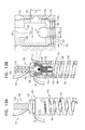
- FIGS. 5A-D are schematic illustrations of a tricuspid valve repair procedure using the tissue-anchor system of FIGS. 1A-F and 2 A-B in a right atrium, in accordance with an application of the present invention
- FIGS. 6A-E are schematic illustrations of a tricuspid-mitral valve repair procedure, in accordance with an application of the present invention.
- FIG. 7 is a schematic illustration of a heart upon conclusion of the tricuspid-mitral valve repair procedure of FIGS. 6A-E , in accordance with an application of the present invention
- FIG. 8 is a schematic illustration of a multiple tissue-anchor system, in accordance with an application of the present invention.
- FIG. 9 is a schematic illustration of the multiple tissue-anchor system of FIG. 8 applied to a tricuspid valve, in accordance with an application of the present invention.
- FIGS. 10A-B are schematic illustrations of the multiple tissue-anchor system of FIG. 8 applied to a right ventricle, in accordance with an application of the present invention
- FIGS. 11A-D are schematic illustrations of a cutting tool, in accordance with an application of the present invention.
- FIGS. 12A-C are schematic illustrations of a tissue anchor system in an engaged state, in accordance with an application of the present invention.
- FIGS. 13A-B and 14 A-B are schematic illustrations of the tissue anchor system of
- FIGS. 12A-C in a disengaged state, in accordance with an application of the present invention
- FIG. 15 is a schematic illustration of another configuration of the tissue anchor system of FIGS. 12A-C , in accordance with an application of the present invention.
- FIGS. 16A-C are schematic illustrations of two exemplary deployments of a tissue anchor of the tissue anchor system of FIGS. 12A-14B using a torque-delivery tool of the tissue anchor system of FIGS. 12A-14B , in accordance with respective applications of the present invention
- FIGS. 17A-19 are schematic illustrations of a flexible tether, in accordance with an application of the present invention.
- FIGS. 20A-C are schematic illustrations of cross sections of the flexible tether of FIGS. 17A-19 , in accordance with an application of the present invention.
- FIGS. 21A-C are schematic illustrations of another configuration of the flexible tether of FIGS. 17A-19 , in accordance with an application of the present invention.
- FIG. 22 is a schematic illustration of one use of the flexible tether of FIGS. 20A-C , in accordance with an application of the present invention.
- FIGS. 23A-B are schematic illustrations of one use of the flexible tether of FIGS. 21A-C , in accordance with an application of the present invention.
- FIGS. 24A-C are schematic illustrations of one use of the tether described hereinabove with reference to FIG. 21A-C , in accordance with an application of the present invention.
- FIGS. 1A-F are schematic illustrations of a tissue-anchor system 10 in an unlocked state, in accordance with an application of the present invention.
- FIGS. 2A-B are schematic illustrations of tissue-anchor system 10 in a locked state, in accordance with an application of the present invention.
- Tissue-anchor system 10 comprises a torque-delivery tool 20 , a tether 22 , and a tissue anchor 24 .
- Torque-delivery tool 20 is configured to implant tissue anchor 24 in cardiac tissue, and to thereafter lock tether 22 to tissue anchor 24 , such that sliding of tether 22 with respect to tissue anchor 24 is inhibited.
- tether 22 is tensioned after tissue anchor 24 has been implanted in the cardiac tissue, and after the tether has been tensioned, tether 22 is locked to tissue anchor 24 .
- Torque-delivery tool 20 comprises (a) a torque-delivery cable 28 , which comprises a distal torque-delivery head 30 , (h) a distal coupling element 32 that is fixed to a distal end 34 of distal torque-delivery head 30 , and (c) a distal spring depressor 36 .
- Tissue anchor 24 comprises (a) a tissue-coupling element 50 , and (b) a proximal anchor head 52 , which is attached to a proximal portion 54 of tissue-coupling element 50 .
- tissue-coupling element 50 comprises a helical tissue-coupling element, which punctures and screws into cardiac tissue.
- tissue-coupling element 50 implements features of one or more of the tissue-coupling elements described in PCT Application PCT/IL2014/050027, filed Jan. 9, 2014, which published as PCT Publication WO 2014/108903 and is incorporated herein by reference.
- Anchor head 52 comprises an axially-stationary shaft 56 and a tether-locking mechanism 68 .
- Axially-stationary shaft 56 (which can best be seen in FIGS. 1D-F ) has (a) a distal portion 58 that is axially fixed with respect to proximal portion 54 of tissue-coupling element 50 , and (b) a proximal end 60 that comprises a proximal coupling element 62 .
- Distal and proximal coupling elements 32 and 62 are shaped so as to define corresponding interlocking surfaces, which facilitate coupling of distal torque-delivery head 30 to axially-stationary shaft 56 .
- Tether-locking mechanism 68 comprises:
- At least a portion of spring 70 radially surrounds axially-stationary shaft 56 , such as shown in FIG. 1D .
- at least a portion of spring 70 is helical, such as shown in FIGS. 1D, 2A -B, and 3 A (e.g., the entire spring is helical, such as shown in FIGS. 1D and 2A -B), while for other applications, spring 70 is not helical, such as described hereinbelow with reference to FIGS. 3B-E .
- Tissue-anchor system 10 is configured to assume:
- tissue-anchor system 10 When tissue-anchor system 10 is in the unlocked state, tether-locking mechanism 68 is also in an unlocked state, in which state spring 70 does not inhibit sliding of tether 22 through lateral opening 82 .
- tether-locking mechanism 68 When tissue-anchor system 10 is in the locked state, tether-locking mechanism 68 is also in a locked state, in which state spring 70 inhibits the sliding of tether 22 through lateral opening 82 by pressing tether 22 against outer tether-securing element 80 , such as against perimeter 84 of lateral opening 82 , and/or an inner surface of outer tether-securing element 80 .
- Tissue-anchor system 10 is advanced into the heart in the unlocked state.
- Tissue anchor 24 is implanted in cardiac tissue, using torque-delivery cable 28 while tissue-anchor system 10 is in the unlocked state.
- tension is applied to tether 22 .
- torque-delivery cable 28 (including distal torque-delivery head 30 ) is decoupled from axially-stationary shaft 56 of tissue anchor 24 , thereby allowing spring 70 to expand and press tether 22 against outer tether-securing element 80 .
- This pressing locks tether 22 with respect to tissue anchor 24 , and maintains the distance and tension between tissue anchor 24 and one or more other implanted tissue anchors, such as described hereinbelow with reference to FIGS. 5C and 6E .
- tissue-anchor system 10 is used to implant tissue anchor 24 in non-cardiac tissue of a subject, in which case tissue-anchor system 10 is advanced into another location in the subject's body.
- Torque-delivery cable 28 (including distal torque-delivery head 30 ) thus serves two functions:
- anchor head 52 further comprises a hammer cap 100 , which is fixed to spring 70 , and covers at least a portion 102 of spring 70 , including a proximal end 104 of spring 70 . (For clarity of illustration of other elements, hammer cap 100 is not shown in FIGS.
- the hammer cap is optionally present.
- spring 70 presses tether 22 against outer tether-securing element 80 by pressing hammer cap 100 against outer tether-securing element 80 , such as perimeter 84 of lateral opening 82 , and/or an inner surface of outer tether-securing element 80 .
- Hammer cap 100 may prevent entanglement of tether 22 with spring 70 .
- providing hammer cap 100 may obviate the need to weld a distal end of spring 70 to anchor head 52 , because the hammer cap surrounds at least a portion of the spring and thereby couples the spring to the anchor head.
- tether 22 prevents hammer cap 100 from proximally exiting outer tether-securing element 80 .
- one or more small pins 108 are provided that extend radially inward from an inner surface of outer tether-securing element 80 ; the pins prevent the hammer cap from proximally exiting the outer tether-securing element.
- tissue-anchor system 10 further comprises a locking wire 110 .
- Torque-delivery cable 28 (including distal torque-delivery head 30 ), distal coupling element 32 , proximal coupling element 62 , and axially-stationary shaft 56 are shaped so as define respective channels 72 , 74 , 76 , and 78 therethrough, which are radially aligned with each other and coaxial with tissue anchor 24 .
- tissue-anchor system 10 is in the unlocked state, a portion of locking wire 110 is disposed in the channels, thereby preventing decoupling of distal and proximal coupling elements 32 and 62 from one another. Proximal withdrawal and removal of the portion of locking wire 110 from the channels allows the decoupling of distal and proximal coupling elements 32 and 62 from one another.
- locking wire 110 is shaped so as to define a sharp distal tip 727 .
- tissue-coupling element 50 typically is helical, and locking wire 110 is initially removably positioned within a channel defined by the helix. As tissue-coupling element 50 is screwed into tissue, locking wire 110 penetrates and advances into the tissue along with the anchor to a certain depth in the tissue. For some applications, when the locking wire penetrates to the certain depth, the locking wire is withdrawn slightly. Typically, after tissue-coupling element 50 has been fully implanted, locking wire 110 is withdrawn entirely from the tissue, and removed from the subject's body.
- sharp distal tip 727 of locking wire 110 is inserted into the tissue slightly, even before insertion of tissue-coupling element 50 , in order to inhibit sliding of the tissue-coupling element on the surface of the tissue before commencement of insertion of the tissue-coupling element into the tissue.
- outer tether-securing element 80 is rotatable with respect to tissue-coupling element 50 and axially-stationary shaft 56 , in order to provide rotational freedom of movement to tether 22 after implantation of tissue anchor 24 , particularly during tensioning of tether 22 .
- This rotational freedom of movement avoids twisting of the tether around the anchor head, and facilitates ideal orientation of the tether with another tissue anchor.
- outer tether-securing element 80 has an outer diameter of at least 1 mm, no more than 6 mm, and/or between 1 and 6 mm.
- tissue anchor 24 has an outer diameter of at least 2 mm, no more than 8 mm, and/or between 2 and 8 mm.
- FIG. 3A is a schematic illustration of a tissue anchor 124 , in accordance with an application of the present invention. Except as described below, tissue anchor 124 is generally similar to tissue anchor 24 , and may be used in tissue-anchor system 10 instead of tissue anchor 24 in any of the applications described herein.
- Tissue anchor 124 comprises a spring 126 , which is shaped to provide a proximal surface 128 that presses tether 22 against outer tether-securing element 80 , such as against perimeter 84 of lateral opening 82 , and/or an inner surface of outer tether-securing element 80 , when tissue-anchor system 10 is in the locked state, such as shown in FIG. 3A .
- proximal surface 128 typically, at least a portion of spring 126 that does not provide proximal surface 128 is helical.
- proximal surface 128 is circular.
- Proximal surface 128 may serve as a hammer head that presses tether 22 against outer tether-securing element 80 when tissue-anchor system 10 is in the locked state.
- FIGS. 3B-C are schematic illustrations of a tissue anchor 134 in unlocked and locked states, respectively, in accordance with an application of the present invention. Except as described below, tissue anchor 134 is generally similar to tissue anchor 24 , and may be used in tissue-anchor system 10 instead of tissue anchor 24 in any of the applications described herein.
- Tissue anchor 134 comprises (a) a spring 136 , which comprises an elastic band 138 , and (b) a hammer element 140 .
- Hammer element 140 is shaped to provide a proximal surface 142 that presses tether 22 against outer tether-securing element 80 , such as against perimeter 84 of lateral opening 82 , and/or an inner surface of outer tether-securing element 80 , when tissue-anchor system 10 is in the locked state, as shown in FIG. 3C .
- Elastic band 138 of spring 136 and hammer element 140 are arranged such that elastic band 138 applies a proximal force on a distal end of hammer element 140 .
- proximal surface 142 is circular.
- Proximal surface 142 may serve as a hammer head that presses tether 22 against outer tether-securing element 80 when tissue-anchor system 10 is in the locked state.
- tissue anchor 144 is generally similar to tissue anchor 24 , and may be used in tissue-anchor system 10 instead of tissue anchor 24 in any of the applications described herein.
- Tissue anchor 144 comprises (a) a spring 146 , which comprises an expandable material 148 , and (b) a hammer element 150 .
- expandable material 148 may comprise an expandable elastomeric material, a foam (e.g., foamed silicone), or a sponge, as is known in the materials arts.
- Hammer element 150 is shaped to provide a proximal surface 152 that presses tether 22 against outer tether-securing element 80 , such as against perimeter 84 of lateral opening 82 , and/or an inner surface of outer tether-securing element 80 , when tissue-anchor system 10 is in the locked state, as shown in FIG. 3E .
- Expandable material 148 of spring 146 and hammer element 150 are arranged such that expandable material 148 applies a proximal force on a distal end of hammer element 150 .
- proximal surface 142 is circular.
- Proximal surface 152 may serve as a hammer head that presses tether 22 against outer tether-securing element 80 when tissue-anchor system 10 is in the locked state.
- FIGS. 4A-E are schematic illustrations of friction-enhancing features of tether 22 , in accordance with respective applications of the present invention. These features may be used with tether 22 in any of the configurations described herein.
- the friction-enhancing features enhance friction between the tether and outer tether-securing element 80 , when tissue-anchor system 10 is in the locked state (and tether-locking mechanism 68 is in the locked state). For some applications, these friction-enhancing features enable one-way ratcheting of tether 22 through lateral opening 82 of outer tether-securing element 80 .
- tether 22 typically defines a plurality of securement protrusions 160 spaced at intervals (I) along tether 22 , which protrusions serve as the friction-enhancing features.
- an average interval of securement protrusions 160 along tether 22 is at least 1 mm, no more than 18 mm, and/or between 1 and 18 mm, e.g., at least 3 mm, no more than 18 mm, and/or between 3 and 18 mm.
- securement protrusions 160 have an outer diameter of at least 0.3 mm (e.g., at least 0.4 mm, such as at least 1 mm), no more than 6 mm (such as no more than 1.25 mm), and/or between 0.3 mm and 6 mm, such as between 0.4 mm and 1.25 mm.
- the outer diameter is typically less than the greatest dimension of lateral opening 82 .
- tether 22 comprises between 2 and 20 securement protrusions 160 .
- protrusions 160 comprise respective cylinders 168 on tether 22 , such as shown in FIG. 4A .
- protrusions 160 are defined by respective knots 170 in tether 22 , such as shown in FIG. 4B .
- protrusions 160 comprise respective cones 172 on tether 22 , such as shown in FIG. 4C ; this configuration may restrict retrograde movement of the tether through outer tether-securing element 80 , while allowing antegrade movement.
- protrusions 160 comprise respective scales 174 on tether 22 , such as shown in FIG. 4D .
- protrusions 160 comprise respective beads 176 on tether 22 , such as shown in FIG.
- protrusions 160 comprise a radiopaque material; which enhances fluoroscopy feedback to the user, particularly as the protrusions 160 are advanced through lateral opening 82 during application of tension to tether 22 .
- FIGS. 5A-D are schematic illustrations of a tricuspid valve repair procedure using tissue-anchor system 10 in aright atrium 200 , in accordance with an application of the present invention.
- the procedure is performed using a valve-tensioning implant system 202 .
- Valve-tensioning implant system 202 comprises tissue-anchor system 10 , including torque-delivery tool 20 , tether 22 , and tissue anchor 24 , as described hereinabove with reference to FIGS. 1A-4E .
- tissue anchor 24 serves as a second tissue anchor 24 .
- Valve-tensioning implant system 202 further comprises a first tissue anchor 204 , which typically comprises a helical tissue-coupling element, which punctures and screws into cardiac muscle tissue.
- first tissue anchor 204 implements techniques of one or more of the tissue anchors described in International Application PCT/IL2014/050027, filed Jan. 9, 2014, which published as PCT Publication WO 2014/108903 and is incorporated herein by reference.
- first tissue anchor 204 comprises a clip, jaws, or a clamp which grips and squeezes a portion of cardiac muscle tissue and does not puncture the cardiac muscle tissue.
- a head 208 of first tissue anchor 204 comprises an interface 210 that is configured to rotate with respect to a helical tissue-coupling element 212 of tissue anchor 204 , in order to provide rotational freedom of movement to tether 22 after implantation of the tissue anchor.
- Tether 22 is typically fixed to interface 210 , such that tether 22 cannot slide with respect to interface 210 .
- Valve-tensioning implant system 202 further comprises a catheter 206 and a tool for delivering first tissue anchor 204 .
- the tool implements techniques described with reference to FIGS. 21 and 22A -D of PCT Publication WO 2013/011502, which is incorporated herein by reference, mutatis mutandis.
- catheter 206 comprises a steering mechanism, as is known in the catheter art.
- Valve-tensioning implant system 202 is typically introduced transcatheterly and endovascularly (typically percutaneously), via catheter 206 , with the aid of a guidewire, through vasculature of the subject, such as (a) via the femoral vein, through inferior vena cava 274 , and into right atrium 200 , (b) via the basilic vein, through the subclavian vein through superior vena cava 276 , and into right atrium 200 , or (c) via the external jugular vein, through the subclavian vein through superior vena cava 276 , and into right atrium 200 .
- vasculature of the subject such as (a) via the femoral vein, through inferior vena cava 274 , and into right atrium 200 , (b) via the basilic vein, through the subclavian vein through superior vena cava 276 , and into right atrium 200 , or (c) via the external jugular vein, through the subclav
- the procedure is typically performed with the aid of imaging, such as fluoroscopy, transesophageal, transthoratic echocardiography, ICE, and/or echocardiography.
- imaging such as fluoroscopy, transesophageal, transthoratic echocardiography, ICE, and/or echocardiography.
- the procedure may be performed using techniques described in US Patent Application Publication 2012/0035712, which is assigned to the assignee of the present application and is incorporated herein by reference, with reference to FIGS. 1A-D thereof, mutatis mutandis.
- first tissue anchor 204 is implanted at a first atrial site 292 .
- first atrial site 292 is selected from the group of sites consisting of: an annulus 283 of a tricuspid valve 207 ; and a wall of right atrium 200 above annulus 283 of tricuspid valve 207 .
- first atrial site 292 is located within 1 cm of a site on annulus 283 that circumferentially corresponds to a location that is (a) at or counterclockwise to a point on the annulus that is 1 cm septal (i.e., clockwise) to a posteroseptal commissure 217 , and (b) at or clockwise to a point on the annulus that is 1 cm anterior (i.e., counterclockwise) to an anteroposterior commissure (APC) 324 , as viewed from the right atrium.
- APC anteroposterior commissure
- the location is (a) at posteroseptal commissure 217 , (b) at anteroposterior commissure 324 , or (c) along posterior leaflet 284 ; in other words, the location is (a) at or counterclockwise to posteroseptal commissure 217 , and (b) at or clockwise to anteroposterior commissure 324 , as viewed from the right atrium.
- the location may be at:
- the direction of the 1 cm from the described anatomical sites may be either circumferentially around the annulus, up the wall of right atrium 200 above annulus 283 , or a combination of circumferentially around the annulus and up the wall of the atrium.
- first tissue anchor 204 is implanted at a ventricular site below the level of the valve, typically up to 3 cm below the level of the valve.
- tether 22 may pass through tricuspid valve 207 , such as through a commissure of the valve.
- first tissue anchor 204 has been implanted at first atrial site 292 , the implantation tool is removed from the subject's body, typically leaving catheter 206 in situ.
- Tether 22 thus connects first and second tissue anchors 204 and 24 .
- Valve-tensioning implant system 202 enables this remote coupling of the anchors to one another via catheter 206 .
- second tissue anchor 24 is implanted at a second atrial site 293 using torque-delivery cable 28 of torque-delivery tool 20 .
- Tissue-anchor system 10 including second tissue anchor 24 and torque-delivery cable 28 , is introduced over tether 22 and through delivery tube 214 , which itself is advanced through catheter 206 .
- Tissue-anchor system 10 is introduced in the unlocked state (tether-locking mechanism 68 is also in the unlocked state), as described hereinabove with reference to FIGS. 1A-F .
- Second atrial site 293 is selected from the group of sites consisting of: annulus 283 , and a wall of right atrium 200 above annulus 283 .
- second atrial site 293 is located within 1 cm of a site on annulus 283 that circumferentially corresponds to a location that is (a) at or clockwise to a point on the annulus 1 cm septal (i.e., counterclockwise) to a septoanterior commissure (SAC) 290 , and (b) at or counterclockwise to a point on the annulus 1 cm posterior (i.e., clockwise) to anteroposterior commissure (APC) 324 , as viewed from the right atrium.
- SAC septoanterior commissure
- the location is (a) at septoanterior commissure (SAC) 290 , (b) at anteroposterior commissure (APC) 324 , or (c) along anterior leaflet 286 ; in other words, the location is (a) at or clockwise to septoanterior commissure (SAC) 290 , and (b) at or counterclockwise to anteroposterior commissure (APC) 324 , as viewed from the right atrium.
- the location may be at:
- the direction of the 1 cm from the described anatomical sites may be either circumferentially around the annulus, up the wall of right atrium 200 above annulus 283 , or a combination of circumferentially around the annulus and up the wall of the atrium.
- first and second atrial sites 292 and 293 may be inverted, such as when an approach from superior vena cava 276 is used.
- Second tissue anchor 24 is implanted at second atrial site 293 by rotating torque-delivery cable 28 (including distal torque-delivery head 30 ).
- the size of the tricuspid valve orifice is reduced by tensioning tether 22 , so as to reduce regurgitation.
- tensioning may be performed by proximally pulling on free end 213 tether 22 , such that a portion of tether 22 is pulled through lateral opening 82 of outer tether-securing element 80 of second tissue anchor 24 .
- Tissue-anchor system 10 enables this tension to be applied remotely, i.e., via catheter 206 .
- torque-delivery cable 28 (including distal torque-delivery head 30 ) is decoupled from axially-stationary shaft 56 of second tissue anchor 24 , such as by removing locking wire 110 .
- spring 70 expands and presses tether 22 against outer tether-securing element 80 .
- This pressing transitions tissue-anchor system 10 to the locked state (and tether-locking mechanism 68 to the locked state), by locking tether 22 with respect to tissue anchor 24 .
- Such locking maintains the distance and tension between second tissue anchor 24 and first tissue anchor 204 .
- excess portion 294 of tether 22 remains free in right atrium 200 . It is generally undesirable to leave this excess portion free to move around in the atrium.
- excess portion 294 of tether 22 is cut and removed from the atrium, using a cutting tool 498 , such as thoracoscopic scissors, as known in the art.
- the excess portion is cut using cutting tool 600 , described hereinbelow with reference to FIGS. 11A-D .
- excess portion 294 is secured in a desired disposition in the vasculature of right atrium 200 , such as in inferior vena cava 274 , superior vena cava 276 , or a coronary sinus.
- Valve-tensioning implant system 202 allows first and second anchors 204 and 24 to be delivered separately and connected afterwards in situ. This simplifies the procedure for the operator, and allows an approach from two or more different blood vessels such as transfemoral, transjugular, transradial or transapical approaches, which may provide simpler access to the anchoring point.
- valve-tensioning implant system 202 and tissue-anchor system 10 have been described hereinabove as being used to remodel the tricuspid valve, they may also be used to remodel the mitral valve, unions mutandis, such as using multiple tissue-anchor system 400 , described hereinbelow with reference to FIG. 8 (for example, with a plurality of tissue anchors implanted along the posterior annulus).
- FIGS. 6A-E are schematic illustrations of a tricuspid-mitral valve repair procedure, in accordance with an application of the present invention.
- both the tricuspid and the mitral valves are repaired by simultaneously applying tension across both valves using a tether that passes through the atrial septum.
- valve-tensioning implant system 202 For some applications, the procedure is performed using valve-tensioning implant system 202 , described hereinabove with reference to FIGS. 5A-D .
- tissue anchor 24 serves as a second tissue anchor 24
- valve-tensioning implant system 202 further comprises first tissue anchor 204 , as described hereinabove with reference to FIGS. 5A-D .
- tissue anchor 724 described hereinbelow with reference to FIGS. 12A-14B , or another tissue anchor, may be used as the first tissue anchor.
- Valve-tensioning implant system 202 is typically introduced transcatheterly and endovascularly (typically percutaneously), via catheter 206 , with the aid of a guidewire, through vasculature of the subject, such as (a) via the femoral vein, through the inferior vena cava, and into right atrium 200 , (b) via the basilic vein, through the subclavian vein through the superior vena cava, and into right atrium 200 , or (c) via the external jugular vein, through the subclavian vein through the superior vena cava, and into right atrium 200 .
- vasculature of the subject such as (a) via the femoral vein, through the inferior vena cava, and into right atrium 200 , (b) via the basilic vein, through the subclavian vein through the superior vena cava, and into right atrium 200 , or (c) via the external jugular vein, through the subclavian vein through the superior vena ca
- the procedure is typically performed with the aid of imaging, such as fluoroscopy, transesophageal, transthoratic echocardiography, ICE, and/or echocardiography.
- imaging such as fluoroscopy, transesophageal, transthoratic echocardiography, ICE, and/or echocardiography.
- the procedure may be performed using techniques described in above-mentioned US Patent Application Publication 2012/0035712, with reference to FIGS. 1A-D thereof, mutatis niutandis.
- an opening 300 is made through an atrial septum 302 at a septal site 304 , which is typically at least 5 mm from the fossa ovalis, such as at least 10 mm from the fossa ovalis (shown in FIG. 7 ).
- first tissue anchor 204 is endovascularly advanced to a left-atrial site 306 of a left atrium 308 , the site selected from the group of sites consisting of: a mitral annular site 307 on an annulus of a mitral valve 310 , and a wall of left atrium 308 above the mitral annular site.
- catheter 206 is advanced through opening 300 .
- An inner tube 305 may be advanced through catheter 206 , and a delivery tool may be advanced through inner tube 305 .
- first tissue anchor 204 is implanted at left-atrial site 306 .
- mitral annular site 307 circumferentially corresponds to a posterior leaflet 312 of the mitral valve.
- mitral annular site 307 may circumferentially correspond to an annular site of the mitral valve within 1 cm of a lateral scallop (P1) 313 and/or within 1 cm of a middle scallop (P2) 314 of posterior leaflet 312 .
- first tissue anchor 204 is implanted at any site on the lateral wall of the left side of the heart, atrium, annulus, papillary or any other structure of the left side of the heart or valve that can be used as an anchoring site to move the left lateral wall of the heart septally.
- Inner tube 305 is removed from catheter 206 , and catheter 206 is withdrawn to right atrium 200 .
- the physician threads free end 213 of tether 22 through lateral opening 82 of outer tether-securing element 80 of second tissue anchor 24 , and then through a lumen of a delivery tube 214 of tissue-anchor system 10 (shown in FIG. 5B ), as described hereinabove.
- Tether 22 thus connects first and second tissue anchors 204 and 24 .
- Valve-tensioning implant system 202 enables this remote coupling of the anchors to one another via catheter 206 .
- tissue-anchor system 10 including second tissue anchor 24 and torque-delivery cable 28 , is endovascularly introduced over tether 22 and through delivery tube 214 , which itself is advanced through catheter 206 .
- Tissue-anchor system 10 is introduced in the unlocked state (tether-locking mechanism 68 is also in the unlocked state), as described hereinabove with reference to FIGS. 1A-F .
- the distal end of delivery tube 214 , and second tissue anchor 24 are steered to a right-atrial site 320 of right atrium 200 selected from the group of sites consisting of: a tricuspid annular site 322 on an annulus of tricuspid valve 207 , and a wall of right atrium 200 above tricuspid annular site 322 .
- tricuspid annular site 322 circumferentially corresponds to an annular site of the tricuspid valve that is (a) at or clockwise to a point on the tricuspid annulus 2 cm anterior (i.e., counterclockwise) to anteroposterior commissure (APC) 324 of tricuspid valve 207 , and (b) at or 1 cm counterclockwise to posteroseptal commissure 217 of tricuspid valve 207 , as viewed from the right atrium.
- the annular site is (a) at or clockwise to septoanterior commissure (SAC) 290 , and (b) at or counterclockwise to posteroseptal commissure 217 .
- second tissue anchor 24 is implanted at any site on the lateral wall of the right side of the heart, atrium, annulus, papillary or any other structure of the right side of the heart or valve that can be used as an anchoring site to move the right lateral wall of the heart septally.
- second tissue anchor 24 is implanted at tricuspid annular site 322 by rotating torque-delivery cable 28 (including distal torque-delivery head 30 ).
- the size of the tricuspid valve orifice and the size of the mitral valve orifice are reduced by approximating left-atrial site 306 and right-atrial site 320 by tensioning tether 22 , so as to reduce regurgitation.
- tensioning may be performed by proximally pulling on free end 213 of tether 22 , such that a portion of tether 22 is pulled through lateral opening 82 of outer tether-securing element 80 of second tissue anchor 24 , as indicated by the arrow in FIG. 6D .
- Tissue-anchor system 10 enables this tension to be applied remotely, i.e., via catheter 206 .
- torque-delivery cable 28 (including distal torque-delivery head 30 ) is decoupled from axially-stationary shaft 56 of second tissue anchor 24 , such as by removing locking wire 110 .
- spring 70 expands and press tether 22 against outer tether-securing element 80 .
- This pressing transitions tissue-anchor system 10 to the locked state (and tether-locking mechanism 68 to the locked state), by locking tether 22 with respect to second tissue anchor 24 .
- Such locking maintains the distance and tension between second tissue anchor 24 and first tissue anchor 204 .
- an excess portion 294 of tether 22 remains free in right atrium 200 . It is generally undesirable to leave this excess portion free to move around in the atrium.
- excess portion 294 of tether 22 is cut and removed from the atrium, using a cutting tool 498 , such as thoracoscopic scissors, as known in the art.
- the excess portion is cut using cutting tool 600 , described hereinbelow with reference to FIGS. 11A-D .
- excess portion is secured in a desired disposition in the vasculature of right atrium 200 , such as in inferior vena cava 274 , superior vena cava 276 , or a coronary sinus.
- second tissue anchor 24 is endovascularly advanced to right-atrial site 320 after first tissue anchor 204 has been implanted.
- first tissue anchor 204 is endovascularly advanced to left-atrial site 306 after second tissue anchor 24 has been implanted.
- a multiple-anchor delivery tool may be used with tether 22 pre-threaded through second tissue anchor 24 .
- FIG. 7 is a schematic illustration of a heart upon conclusion of the tricuspid-mitral valve repair procedure of FIGS. 6A-E (after implantation of tether 22 across both atria), in accordance with an application of the present invention.
- tether 22 passes through opening 300 through atrial septum 302 at septal site 304 .
- septal site 304 is typically at least 5 mm from a fossa ovalis 330 , such as at least 10 mm from fossa ovalis 330 .
- septal site 304 is anterior to, and/or apical to, and/or toward the aorta from, fossa ovalis 330 as shown in FIG. 7 , such as near or at the septum secundum and/or septum primum.
- apical to means “in a direction towards the apex of the heart.”
- septal site 304 is at least 3 mm, no more than 20 mm, and/or between 3 and 20 mm (e.g., 10 mm) superior and anterior to a coronary sinus orifice, and/or at least 3 mm, no more than 15 mm, and/or between 3 and 15 mm (e.g., 5 mm) posterior to an aorta.
- 3 and 20 mm e.g. 10 mm
- 3 and 15 mm e.g., 5 mm
- opening 300 The location of opening 300 is selected such that, after the tissue anchors are implanted and tether 22 has been tensioned, an angle of tether 22 at opening 300 of atrial septum 302 is ideally as close as possible to 180 degrees.
- the angle should be at least 120 degrees to avoid excessive force on the atrial septum, such as at least 135 degrees, or at least 150 degrees, and/or less than 180 degrees (in other words, the tether is not straight as it passes through opening 300 ), such as less than 170 degrees, e.g., no more than 150 degrees, such as between 140 and 150 degrees.
- opening 300 should not be too superior and posterior on atrial septum 302 , for example, should not be at fossa ovalis 330 .
- a vertex 350 of the angle of tether 22 at opening 300 typically points at least partially in a posterior direction (as can be seen in FIG. 6E ), at least partially in a superior direction, and/or in at least partially an away-from-apical direction (as can be seen in FIG. 7 ).
- the angle as projected (labeled a (alpha) in FIGS. 6E and 7 ), would be at least 120 degrees, such as at least 135 degrees, or at least 140 degrees.
- the angle as projected is as close as possible to 180 degrees, but in practice the angle as projected is typically less than 180 degrees (i.e., tether 22 is not straight), such as no more than 170 degrees, generally between 140 and 150 degrees.
- the angle as projected (labeled (beta) in FIG. 7 ) would be at least 120 degrees, such as at least 135 degrees, e.g., at least 140 degrees.
- the angle as projected is as close as possible to 180 degrees, but in practice the angle as projected is typically less 180 degrees (i.e., tether 22 is not straight), such as no more than 170 degrees, generally between 150 and 170 degrees.
- a portion 342 of tensioned tether 22 in left atrium 308 between opening 300 of atrial septum 302 (apex 340 ) and first tissue anchor 204 and (b) a plane 344 defined by the annulus of mitral valve 310 form an angle ⁇ (gamma) of less than 30 degrees.
- the procedure described with reference to FIGS. 6A-E further comprises placing, in opening 300 of atrial septum 302 , an annular reinforcement element 360 that is shaped so as to define an opening therethrough.
- Reinforcement element 360 is typically delivered and placed after implanting first tissue anchor 204 , and before implanting second tissue anchor 24 .
- reinforcement element 360 may be delivered using a balloon-expandable device, or reinforcement element 360 may be self-expanding.
- Tether 22 passes through the opening of reinforcement element 360 .
- Reinforcement element 360 is typically annular.
- Reinforcement element 360 distributes the force of tether 22 against opening 300 of atrial septum 302 , which may prevent damage to the atrial septum, such as caused by cutting by the tether.
- reinforcement element 360 is stiffer in one direction, and is placed in opening 300 of atrial septum 302 with the stiffer direction facing away from vertex 350 , i.e., in the direction in which tether 22 applies the greatest force to opening 300 of atrial septum 302 .
- Reinforcement element 360 may optionally also be configured to close opening 300 of atrial septum 302 , and/or to reduce a size of opening 300 upon withdrawal of catheter 206 from the opening.
- a radially inner surface of reinforcement element 360 may comprise a material configured to promote tissue growth.
- annular reinforcement element 360 comprises a locking mechanism, which is configured to inhibit sliding of tether 22 through annular reinforcement element 360 when in a locked state.
- the locking mechanism is transitioned from an unlocked state to the locked state after tether 22 has been tensioned, as described above.
- This locking has the effect of fixing the respective distances between opening 300 of atrial septum 302 and the first and the second tissue anchors, and preventing dilation of the annulus of one of the atrioventricular valves and the corresponding reduction in size of the other atrioventricular valve.
- At least 75% of the load in tether 22 is borne by the first and the second tissue anchors, and no more than 25% of the load is borne by locked annular reinforcement element 360 , thereby reducing the likelihood that annular reinforcement element 360 might tear or otherwise damage atrial septum 302 .
- tissue-anchoring and/or tether tensioning techniques may be used.
- tissue anchors and/or tensioning techniques may be used that are described in one or more of the patent applications listed and incorporated by reference hereinbelow.
- FIG. 8 is a schematic illustration of a multiple tissue-anchor system 400 , in accordance with an application of the present invention.
- Multiple tissue-anchor system 400 comprises three or more tissue anchors, which are coupled together by tether 22 and cinched together in situ.
- multiple tissue-anchor system 400 may comprise first, second, and third tissue anchors 420 , 422 , and 424 , arranged such that second tissue anchor 422 is positioned along tether 22 between first and third tissue anchors 420 and 424 .
- first tissue anchor 420 may, for example, implement any of the features of (a) tissue anchor 204 , described hereinabove with reference to FIG. 5A-D (configuration not shown in FIG. 8 ), or (b) tissue anchor 724 , described hereinbelow with reference to FIGS. 12A-14B (configuration shown in FIG. 8 ).
- Second tissue anchor 422 comprises a tissue anchor 24 (including tether-locking mechanism 68 ), described hereinabove with reference to FIGS. 1A-F , 2 A-B, and 3 A-E
- third tissue anchor 424 comprises a tissue anchor 24 (including tether-locking mechanism 68 ), described hereinabove with reference to FIGS. 1A-F , 2 A-B, and 3 A-E.
- each of the tissue anchors is delivered using a separate, respective delivery tool.
- the tissue anchor(s) that comprise tether-locking mechanism 68 may be delivered using torque-delivery tool 20 , described hereinabove with reference to FIGS. 1A-F , 2 A-B, and 5 B-C, and the tissue anchor(s) that do not comprise tether-locking mechanism 68 may be delivered using a tool 440 , which implements the features of the tool described hereinabove with reference to FIG. 5A .
- first tissue anchor 420 is first implanted at a first atial site 450 , such as anteroposterior commissure (APC) 324 , or any of the other right-atrial sites described herein above.
- APC anteroposterior commissure
- second tissue anchor 422 is implanted at a second atrial site 452 , such as posteroseptal commissure 217 or any of the other right-atrial sites described hereinabove.
- Tether 22 is tensioned between first and second tissue anchors 420 and 422 , thereby pulling APC 324 and posteroseptal commissure 217 toward one another, resulting in at least partial bicuspidization.
- Tether-locking mechanism 68 of second tissue anchor 422 is locked, as described hereinabove.
- tether 22 comprises another set of friction-enhancing features along the portion of the tether than passes through the head of second tissue anchor 422 (not shown in FIG. 9 , but shown in FIG. 8 ).
- third tissue anchor 424 is implanted at a third atrial site 454 , such as septoanterior commissure (SAC) 290 , or any of the other right-atrial sites described hereinabove.
- SAC septoanterior commissure
- Tether 22 is tensioned between second and third tissue anchors 422 and 424 , thereby pulling SAC 290 and posteroseptal commissure 217 (and APC 324 to some extent) toward one another.
- Tether-locking mechanism 68 of third tissue anchor 424 is locked, as described hereinabove. Excess tether 22 is cut or secured, such as described above.
- second tissue anchor 422 does not comprise tether-locking mechanism 68 , and tension is applied between APC 324 and posteroseptal commissure 217 , and between SAC 290 and posteroseptal commissure 217 , after third tissue anchor 424 has been implanted, and then tether-locking mechanism 68 of third tissue anchor 424 is locked.
- third tissue anchor 424 may decide during the procedure not to implant third tissue anchor 424 , such as if a sufficient reduction in regurgitation is achieved using only the first two anchors. Not implanting third tissue anchor 424 is possible because the tissue anchors are threaded over tether 22 one at a time during the procedure.
- valve-tensioning implant system 202 is used to remodel a pathologically dilated ventricular chamber, or to reduce future ventricular dilation, by applying tension between first and second tissue anchors 204 and 24 implanted in a left or right ventricle, such as in a papillary muscle or wall of the ventricle.
- This technique may improve ventricular pumping efficiency and/or reduce tricuspid or mitral regurgitation.
- this technique might be considered as creating a second artificial moderator band.
- FIGS. 10A-B are schematic illustrations of multiple tissue-anchor system 400 applied to a right ventricle 500 , in accordance with an application of the present invention.
- multiple tissue-anchor system 400 is used to treat dilated right ventricle 500 , as shown in FIG. 10A .
- First tissue anchor 420 is first endovascularly (e.g., percutaneously) advanced to and implanted, from within right ventricle 500 , at a first ventricular wall site 510 , typically on a posterior or an anterior wall below the level of the papillary muscles.
- second tissue anchor 422 is endovascularly (e.g., percutaneously) advanced to and implanted, from within right ventricle 500 , at a second ventricular wall site 512 , typically on the anterior wall above the level of or at the junction of the natural moderator band and the anterior wall, typically no more than 2.5 cm from first ventricular wall site 510 , depending on the extent of dilation of the ventricle.
- Tether 22 is tensioned between first and second tissue anchors 420 and 422 , thereby approximating first and second ventricular wall sites 510 and 512 , and plicating the wall.
- Tether-locking mechanism 68 of second tissue anchor 422 is locked, as described hereinabove.
- third tissue anchor 424 is endovascularly (e.g., percutaneously) advanced to and implanted, from within right ventricle 500 , at a third ventricular wall site 514 on an interventricular septum 520 , typically between the right ventricular outflow tract (RVOT) and a junction of the natural moderator band and an interventricular septal wall.
- Tether 22 is tensioned between second and third tissue anchors 422 and 424 , thereby approximating (a) plicated (approximated) first and second ventricular wall sites 510 and 512 , collectively, and (b) third ventricular wall site 514 .
- Tether-locking mechanism 68 of third tissue anchor 424 is locked, as described hereinabove.
- tether 22 is cut or secured, such as described above.
- tether 22 functions as an artificial moderator band, reducing ventricular dilation, such as by resisting movement of the anterior wall as the ventricle fills during diastole.
- second tissue anchor 422 does not comprise tether-locking mechanism 68 , and tension is applied between first and second ventricular wall site 510 and 512 , and between these sites and third ventricular wall site 514 , after third tissue anchor 424 has been implanted, and then tether-locking mechanism 68 of third tissue anchor 424 is locked.
- tether 22 is electrically conductive, in order to facilitate conduction of natural cardiac electrical signals from the wall of interventricular septum 520 to the anterior wall of right ventricle 500 , mimicking one of the natural functions of the natural moderator band.
- tether 22 is elastic, in order to facilitate diastolic relaxation of the right ventricle.
- tether 22 may be sufficiently elastic to lengthen by at least 10%, no more than 100%, and/or between 10% and 100% under diastolic loading, compared to under systolic loading.
- tissue anchors other than those of multiple tissue-anchor system 400 are used. These other tissue anchors do not comprise tether-locking mechanism 68 . Typically, these other tissue anchors comprise respective helical tissue-coupling elements, as is known in the art. For some applications, tissue anchors are used that are described in International Application PCT/IL2014/050027, which published as PCT Publication WO 2014/108903, and/or in one or more of the other patent applications incorporated by reference hereinbelow.
- FIGS. 11A-D are schematic illustrations of a cutting tool 600 , in accordance with an application of the present invention.
- Cutting tool 600 is configured to cut an elongate member 610 , such as tether 22 described above, or any other elongate member, such as a suture; elongate member 610 is typically flexible.
- Cutting tool 600 is configured to be used in transcatheter procedures.
- Cutting tool 600 uses torsion to cut elongate member 610 , which places no tension on the implant, such as the implanted anchors described hereinabove, and provides a high degree of control of the cutting.
- Cutting tool 600 comprises an outer tube 620 and an inner tube 622 that is nested within outer tube 620 .
- both the inner and the outer tubes are cylindrical.
- outer tube 620 comprises a braided extruded material, such as a metal (such as stainless steel) and nylon
- inner tube 622 comprises a metal (such as stainless steel).
- a proximal end of inner tube 622 is fixed (e.g., welded) to a distal end of a torque cable, which typically comprises a metal (such as stainless steel).
- Inner tube 622 is shaped so as to define an inner-tube distal end (non-lateral) opening 624 through a distal end 626 of inner tube 622 .
- Inner tube 622 is also shaped so as to define an inner-tube lateral opening 628 , typically having a distal-most portion 629 that is within 5 mm of distal end 626 , such as within 3 mm of the distal end.
- inner-tube lateral opening 628 has an area of between 1 and 10 mm2.
- Elongate member 610 before being cut, passes through both inner-tube distal end opening 624 and inner-tube lateral opening 628 , such as shown in FIGS. 11A-C .
- Outer tube 620 is shaped so as to define an outer-tube distal end (non-lateral) opening 630 through a distal end 632 of outer tube 620 .
- Outer tube 620 is also shaped so as to define an outer-tube lateral opening 634 , which extends to distal end 632 .
- a proximal portion 640 of outer-tube lateral opening 634 has a first width W 1 that is greater than (e.g., at least 125% of) a second width W 2 of a distal portion 642 of outer-tube lateral opening 634 , which distal portion 642 extends to distal end 632 .
- First and second widths W 1 and W 2 are measured circumferentially around outer tube 620 .
- first width W 1 may be at least 1.5 mm, no more than 5 mm, and/or between 1.5 and 5 mm
- second width W 2 may be at least 0.5 mm, no more than 1.25 mm, and/or between 0.5 and 1.25.
- Second width W 2 is greater than (e.g., at least 125% of) a diameter D of elongate member 610 , in order to allow the elongate member to pass through distal portion 642 , as described hereinbelow with reference to FIG. 11B .
- proximal portion 640 of outer-tube lateral opening 634 has a first length L 1 of at least 0.5 mm, no more than 2 mm, and/or between 0.5 and 2 mm
- distal portion 642 of outer-tube lateral opening 634 has a second length L 2 of at least 0.5 mm, no more than 2 mm, and/or between 0.5 and 2 mm.
- First and second lengths L 1 and L 2 are measured parallel to a longitudinal axis 648 of outer tube 620 .
- Proximal portion 640 of outer-tube lateral opening 634 has first and second edges 650 A and 650 B, which extend axially along outer tube 620 .
- One or both of the edges are shaped so as to define a sharp cutting blade.
- Outer tube 620 typically has an inner diameter of at least 0.75 mm, no more than 4 mm, and/or between 0.75 and 4 mm, and inner tube 622 typically has an outer diameter that is as least 90%, no more than 99%, and/or between 90% and 99% of the inner diameter of outer tube 620 , and/or at least 0.65 mm, no more than 3.95 mm, and/or between 0.65 and 3.95 mm.
- Outer tube 620 typically has a length of at least 20 cm, no more than 200 cm, and/or between 20 and 200 cm.
- Inner tube 622 typically has a length of at least 1 cm, no more than 200 cm, and/or between 1 and 200 cm (for applications in which inner tube is fixed to the distal end of a torque cable, as described above, inner tube 622 typically has a length of at least 1 cm, no more than 5 cm, and/or between 1 and 5 cm; for applications in which inner tube 622 is not coupled to a torque cable, and thus extends out of the body, the length is typically at least 20 cm, no more than 200 cm, and/or between 20 and 200 cm.
- elongate member 610 is threaded through both inner-tube distal end opening 624 and inner-tube lateral opening 628 , as shown in FIG. 11A .
- This threading is performed by passing a free proximal end of the elongate member through the tool, while the free end and the tool are outside the subject's body.
- a proximal portion of the elongate member extends proximally generally alongside an outer surface of outer tube 620 , to outside the subject's body (typically through a catheter through which cutting tool 600 also passes).
- Distal end 626 of inner tube 622 is distal to distal end 632 of outer tube 620 , such that a distal portion of inner tube 622 extends out of outer-tube distal end opening 630 , typically by at least 1 mm, no more than 10 mm, and/or between 1 to 10 mm.
- This relative axial positioning of the inner and outer tubes allows free sliding of elongate member 610 as cutting tool 600 is advanced to a desired cutting location along the elongate member.
- At least a portion, such as all, of inner-tube lateral opening 628 is disposed distally to distal end 632 of outer tube 620 .
- inner tube 622 is moved proximally with respect to outer tube 620 , either by proximally withdrawing the inner tube and/or by distally advancing the outer tube.
- a portion of elongate member 610 passes through distal portion 642 of outer-tube lateral opening 634 during such relative movement.
- a distal edge 660 of inner-tube lateral opening 628 presses elongate member 610 against a proximal edge 662 of outer-tube lateral opening 634 (which edge is typically dull), causing a proximal portion of the elongate member to extend radially outward from cutting tool 600 , typically at an angle of between 60 and 90 degrees with respect to an outer surface of outer tube 620 . (Such a disposition of the elongate member no longer provides free sliding of the elongate member; for this reason the inner tube is initially disposed distal to the outer tube, to allow such free sliding.)
- inner tube 622 is rotated with respect to outer tube 620 , either by rotating the inner tube and/or by rotating the outer tube. Such rotation pushes elongate member 610 against one of sharp first and second edges 650 A and 650 B of proximal portion 640 of outer-tube lateral opening 634 .
- Inner and outer tubes 622 and 620 are torqued in opposite rotational directions to apply shear on elongate member 610 with the sharp blade edge, causing the sharp edge to cut elongate member 610 , as shown in FIG. 11D .
- cutting tool 600 performs the cutting with torsional force, rather than axial force.
- FIGS. 12A-149 are schematic illustrations of a tissue-anchor system 710 , in accordance with an application of the present invention.
- FIGS. 12A-C show tissue-anchor system 710 in an engaged state
- FIGS. 13A-B and 14 A-B show tissue-anchor system 710 in a disengaged state.
- Tissue-anchor system 710 comprises a torque-delivery tool 720 , a tissue anchor 724 , and a locking shaft 726 , which is typically shaped so as to define a sharp distal tip 727 .
- Locking shaft 726 is similar in many respects to locking wire 110 , described hereinabove with reference to FIGS. 1A-2A .
- Torque-delivery tool 720 is configured to implant tissue anchor 724 in cardiac tissue, and comprises a torque-delivery cable 728 , which comprises a distal torque-delivery head 730 , which is fixed to torque-delivery cable 728 .
- Distal torque-delivery head 730 is shaped so as to define a chamber 732 , which is shaped so as to define (a) a fenestration 734 through a lateral wall 736 of chamber 732 , and (b) proximal and distal chamber end openings 738 and 740 .
- Torque-delivery tool 720 further comprises a coupling element 741 , which is (a) not fixed to any elements of tissue-anchor system 710 , (b) too large to pass through fenestration 734 , (c) too large to pass through distal chamber end opening 740 , and, optionally, (d) too large to pass through proximal chamber end opening 738 .
- fenestration 734 has a greatest dimension (e.g., a greatest diameter) D F of at least 0.3 mm, no more than 3 mm, and/or between 0.3 mm and 3 mm, and/or distal chamber end opening 740 has a greatest dimension (e.g., a greatest diameter) D EO of at least 0.25 mm, no more than 2.9 mm, and/or between 0.25 and 2.9 mm.
- Tissue anchor 724 comprises:
- proximal anchor head 752 of tissue anchor 724 is typically shorter than proximal anchor head 52 of tissue anchor 24 , described hereinabove with reference to FIGS. 1A-3E .
- the shorter anchor head allows tissue anchor 724 to be drawn closer to another tissue anchor when tension is applied using a tether, than can be achieved with tissue anchor 24 .
- two tissue anchors 724 are used, they can be drawn even closer to one another when tension is applied using a tether, than can be achieved with two tissue anchors 24 .
- helical tissue-coupling element 750 implements features of one or more of the tissue-coupling elements described in PCT Application PCT/IL2014/050027, filed Jan. 9, 2014, which published as PCT Publication WO 2014/108903 and is incorporated herein by reference.
- tissue-anchor system further comprises tether 22 , which is coupled (optionally, fixed) to anchor head 752 , and which typically is tensioned after tissue anchor 724 has been implanted in cardiac tissue.
- Torque-delivery cable 728 and distal torque-delivery head 730 together are shaped so as to define a locking-wire-accepting channel 760 (labeled in FIGS. 13B and 14B ).
- Locking-wire-accepting channel 760 passes through (i) torque-delivery cable 728 , (ii) chamber 732 (and, typically, the entire distal torque-delivery head 730 ), and (iii) proximal and distal chamber end openings 738 and 740 .
- locking-wire-accepting channel 760 is typically coaxial with helical tissue-coupling element channel 751 .
- Tissue-anchor system 710 is configured to assume engaged and disengaged states, in which distal torque-delivery head 730 is engaged and not engaged to anchor head 752 , respectively.
- Tissue-anchor system 710 is in:
- FIGS. 13A-B and 14 A-B show tissue-anchor system 710 in the disengaged state.
- tissue-anchor system 710 is shown in the disengaged state, while distal torque-delivery head 730 is still in head-coupling channel 756 of anchor head 752 .
- coupling element 741 has fallen away from internal wall 758 of head-coupling channel 756 , such that coupling element 741 no longer axially locks distal torque-delivery head 730 with respect to head-coupling channel 756 . This allows the removal of distal torque-delivery head 730 from head-coupling channel 756 of anchor head 752 , as shown in FIGS. 14A-B .
- coupling element 741 is trapped in chamber 732 because the coupling element is too large to pass through fenestration 734 and too large to pass through distal chamber end opening 740 , and, typically, proximal chamber end opening 738 . Coupling element 741 thus cannot be released into the patient's body.
- coupling element 741 is spherical (as shown), and may, for example, have a diameter D CE of at least 0.3 mm, no more than 3 mm, and/or between 0.3 and 3 mm.
- coupling element 741 has a volume of at least 0.3 mm3, no more than 8 mm3, and/or between 0.3 and 8 mm3.
- coupling element 741 comprises a metal.
- coupling element 741 comprises a polymer, such as an elastomer.
- internal wall 758 of head-coupling channel 756 is shaped so as to define a coupling indentation 762 .
- Tissue-anchor system 710 is in the engaged state when locking shaft 726 is removably disposed in locking-wire-accepting channel 760 and at least partially within helical tissue-coupling element channel 751 , with locking shaft 726 constraining coupling element 741 to partially protrude through fenestration 734 out of chamber 732 and into coupling indentation 762 of the internal wall 758 of head-coupling channel 756 .
- torque-delivery tool 720 further comprises a depth-finding tool 764 , which comprises a radiopaque bead 766 shaped so as to define a hole 768 therethrough (labeled in FIGS. 139 and 149 ).
- Bead 766 is removably positioned within helical tissue-coupling element channel 751 .
- Locking shaft 726 passes through hole 768 of bead 766 , such that bead 766 is slidable along locking shaft 726 and along helical tissue-coupling element channel 751 , when locking shaft 726 is removably disposed at least partially within helical tissue-coupling element channel 751 when tissue-anchor system 710 is in the engaged state.
- depth-finding tool 764 further comprises a bead-coupling wire 770 , which is at least partially removably disposed within helical tissue-coupling element channel 751 , and which is fixed to bead 766 and a distal portion 772 of distal torque-delivery head 730 (labeled in FIGS. 13B and 14A ), thereby (a) preventing bead 766 from exiting a distal end 774 of helical tissue-coupling element channel 751 , and (b) facilitating removal of depth-finding tool 764 from tissue anchor 724 upon removal of distal torque-delivery head 730 from anchor head 752 .
- bead-coupling wire 770 is shaped as a helical spring 776 , such as shown.
- depth-finding tool 764 implements techniques described in PCT Publication WO 2014/108903, which is incorporated herein by reference.
- bead 766 serves as a marker that indicates a depth of penetration of helical tissue-coupling element 750 into soft tissue, such as cardiac tissue.
- helical tissue-coupling element 750 penetrates and is advanced into the tissue.
- Bead 766 does not penetrate the tissue, and thus remains at the surface of the tissue, in contact therewith.
- the bead remains stationary, and moves toward a proximal end of tissue anchor 724 (and toward anchor head 752 and distal torque-delivery head 730 ).
- the proximal end of tissue anchor 742 (and anchor head 752 and distal torque-delivery head 730 ) move closer to bead 766 , as measured along a central longitudinal axis of tissue anchor 742 .
- Both the bead and more proximal portions of the anchor are viewed using imaging (e.g., fluoroscopy, computed tomography, echocardiography, sonography, or MRI), and the distance between the bead and the proximal end of the tissue anchor (e.g., the anchor head) is estimated and monitored in real time as the anchor is advanced into the tissue.
- imaging e.g., fluoroscopy, computed tomography, echocardiography, sonography, or MRI
- the distance between the bead and the proximal end of the tissue anchor e.g., the anchor head
- the tissue-coupling element has been fully advanced, e.g., screwed, into and embedded in the tissue, and the physician thus ceases rotating the anchor.
- tissue anchor Without using a technique such as this for visualizing the advancement of the anchor into the tissue, it is often difficult to ascertain when the tissue anchor has been fully embedded into the tissue, because the tissue is difficult to see in some images, such as fluoroscopic images. As a result, the tissue anchor may inadvertently be insufficiently advanced into the tissue, resulting in poor anchoring in the tissue, or over-advanced into the tissue, possible tearing or otherwise damaging the tissue.
- Bead 766 may have any appropriate shape, such as a sphere (as shown) or a disc (not shown).
- An outer diameter of the bead is typically slightly greater than the inner diameter of an empty space within helical tissue-coupling element 750 , in order to provide some friction between the bead and helical tissue-coupling element 750 , and prevent the bead from being free-floating within the helix.
- the outer diameter of the bead may be at least 0.05 microns less than the inner diameter of the empty space.
- the bead comprises a coating which provides some friction between the bead and the helix; the coating may be sheared off as the bead moves proximally through the helix.
- the bead and shaft are configured to provide some friction therebetween.
- the outer diameter of the bead may be between 1 and 5 mm.
- FIGS. 13A-B show helical spring 776 axially compressed, with bead 766 as close as possible to anchor head 752 and distal torque-delivery head 730 .
- a state is reached when bead 766 pushes against tissue.
- FIGS. 13A-B nevertheless show helical spring 776 axially compressed, because the spring is typically in this state upon and after removal of locking shaft 726 , which removal is performed after the anchor has been implanted in the tissue and the tissue has pushed the bead up against the anchor head.
- anchor head 752 is shaped so as to define a tether-securing element 780 , which is typically shaped so as to define a lateral opening 782 through which tether 22 is disposed.
- tether-securing element 780 is rotatable with respect to helical tissue-coupling element 750 , in order to provide rotational freedom of movement to tether 22 after implantation of tissue anchor 724 , particularly during tensioning of tether 22 . This rotational freedom of movement avoids twisting of the tether around anchor head 752 , and facilitates ideal orientation of the tether with another tissue anchor.
- Tissue-anchor system 710 is advanced into the heart in the engaged state.
- Tissue anchor 724 is implanted in cardiac tissue, using torque-delivery cable 728 while tissue-anchor system 710 is in the engaged state.
- locking shaft 726 which is disposed within locking-wire-accepting channel 760 and helical tissue-coupling element channel 751 , penetrates and advances into the tissue along with the tissue anchor.
- the locking shaft is withdrawn slightly.
- sharp distal tip 727 of locking shaft 726 is inserted into the tissue slightly, even before insertion of tissue anchor 724 , in order to prevent sliding of the anchor on the surface of the tissue before commencement of insertion of the anchor into the tissue.
- locking shaft 726 is withdrawn entirely from the tissue, from helical tissue-coupling element channel 751 , and from locking-wire-accepting channel 760 , thereby allowing the disengagement of distal torque-delivery head 730 from anchor head 752 , as described hereinabove with reference to FIGS. 13A-B and 14 A-B. Because depth-finding tool 764 is fixed to distal torque-delivery head 730 , removal of distal torque-delivery head 730 from anchor head 752 removes depth-finding tool 764 , including radiopaque bead 766 , from tissue anchor 724 .
- Radiopaque bead 766 from the empty space within helical tissue-coupling element 750 allows for greater integration of the helical tissue-coupling element with cardiac tissue.
- bead-coupling wire 770 is shaped as helical spring 776 , as described above, removal of radiopaque bead 766 and helical spring 776 prevents the radiopaque bead and the spring from compressing the tissue in the space within the helical tissue-coupling element on a long-term basis.
- FIG. 15 is a schematic illustration of another configuration of tissue anchor system 710 , in accordance with an application of the present invention.
- locking shaft 726 is shaped so as to define one or more longitudinally-extending grooves 778 , such as exactly one groove 778 as shown in FIG. 15 .
- locking shaft 726 is shaped so as to define one or more longitudinally-extending flat surfaces, such as a plurality of longitudinally-extending flat surfaces facing in respective different directions (for example, locking shaft 726 may be polygonal in cross-section, such as hexagonal) (configurations not shown).
- the groove or flat surface helps better seat and secure coupling element 741 , by providing a greater contact surface area between the shaft and the coupling element.
- the groove or flat surface also allows for the use of a larger coupling element 741 , which may also increase the contact surface area between the shaft and the coupling element.
- the groove or flat surface may also prevent rotation of the shaft with respect to torque-delivery cable and anchor 724 .
- FIGS. 16A-C are schematic illustrations of three exemplary deployments of tissue anchor 724 using torque-delivery tool 720 , in accordance with respective applications of the present invention. These deployments may be performed using techniques described hereinabove with reference to FIGS. 5A-D mutatis mutandis, and/or described in the patent applications incorporated hereinbelow by reference, mutatis mutandis.
- tissue anchor 724 In the deployment illustrated in FIG. 16A , tissue anchor 724 , described hereinabove with reference to FIGS. 12A-149 , is shown deployed at a first atrial site 790 , and tissue anchor 724 , described hereinabove with reference to FIGS. 1A-F , 2 A-B, 3 A-E, and 5 A-D, is shown deployed at a second atrial site 792 .
- Tether 22 is tensed as described hereinabove regarding tissue anchor 724 .
- tissue anchors 724 are shown deployed at first and second atrial sites 790 and 792 , respectively.
- Respective tethers 22 are fixed to heads of tissue anchors 724 , and are coupled together in tension by a tether-securing device 794 .
- tether-securing device 794 may comprise (a) tether-securing device 330 , described with reference to FIGS. 6A-9 of U.S. application Ser. No. 14/525,668, filed Oct.
- tether-securing device 30 described with reference to FIGS. 1-3 of the '668 application.
- Techniques for deploying the tether-securing device may be used that are described in the '668 application.
- a single tissue anchor 724 is deployed, and a second tissue anchor comprises second tissue anchor 252 B fixed to tether-securing device 230 , both of which are described with reference to FIGS. 4A-5 of the '668 application.
- Tether 22 is provided with securement protrusions 160 , which are described hereinabove with reference to FIGS. 4A-E .
- Tether 22 is fixed to the head of the tissue anchor 724 at first atrial site 790 , and passes through lateral opening 782 of tether-securing element 780 of head 752 of the tissue anchor 724 at second atrial site 792 .
- a tether-locking element 796 is provided. Tether 22 passes through tether-locking element 796 .
- Tether-locking element 796 is configured to allow advancement of securement protrusions 160 through tether-locking element 96 in one direction, and inhibit (typically prevent) advancement of the tether through the tether-locking element in the opposite direction.
- tension is applied to tether 22 by pulling on the tether in a direction indicated by an arrow 798
- one or more of securement protrusions 160 pass through tether-locking element 796 in the direction indicated by arrow 798 , and are prevented from returning through the tether-locking element in the opposite direction, thereby maintaining the tension applied to the tether.
- securement protrusions 160 are shown in FIG. 16C comprising cylinders 168 , the securement protrusions may alternatively comprise the other configuration described hereinabove with reference to FIGS. 4B-E or other configurations.
- FIGS. 17A-19 are schematic illustrations of a flexible tether 822 , in accordance with an application of the present invention.
- FIG. 17C shows tether 822 straight-on from the side.
- FIGS. 18A-B are cross-sectional views of tether 822 taken along lines XVIIA-XVIIA and XVIIB-XVIIB, respectively, of FIG. 17A .
- FIG. 19 shows the cross-sectional views of FIGS. 18A-B superimposed on one another for illustrative purposes.
- Tether 822 may be used, for example, to apply tension between two or more tissue anchors, such as tissue anchors described herein, and/or in the patent applications incorporated by reference hereinbelow.
- tether 822 is sterile when provided, typically in protective packaging.
- Tether 822 at least when tensioned into a straight, non-twisted configuration, such as shown in FIGS. 17A-19 , has a central longitudinal axis 828 , and is shaped so as to define first and second blades 830 A and 830 B (and, typically, at least several more blades), which are disposed (a) at first and second longitudinal locations 832 A and 832 B, and (b) within 10 mm of one another along central longitudinal axis 828 .
- first and second blades 830 A and 830 B are disposed within 5 mm of one another along central longitudinal axis 828 , such as touching one another (as shown in FIGS. 17A-C ).
- First and second blades 830 A and 830 B have respective best-fit planes 834 A and 834 B, which intersect at an angle ⁇ (theta) of at least 30 degrees, such as at least 60 degrees, e.g., at least 85 degrees, for example 90 degrees (as shown).
- adjacent first and second blades 830 A and 830 B are rotationally offset by at least angle ⁇ (theta).
- angle ⁇ (theta) equals 90 degrees
- the blades may be considered to have two rotational phases
- angle ⁇ (theta) is less than 90 degrees
- the blades may be considered to have three or more rotational phases.
- each of the blades defines two opposing generally flat external surfaces that are generally parallel with the blade's best-fit plane.
- a “blade” of tether 822 is a generally flat thin part or section.
- a “blade” does not necessarily define a sharp cutting edge, and, in fact, blades 830 do not generally define any sharp cutting edges.
- a “best-fit plane” of a given blade is the plane that results in the minimum sum of squares of distances between the plane and all points of the volume of the blade.
- an angle between two lines or two planes is the smaller of the two supplementary angles between the two lines or two planes, or equals 90 degrees if the two lines or two planes are perpendicular.
- a “non-twisted configuration” means that the tether is not twisted, i.e., not altered in shape, as by turning the ends in opposite directions, so that parts previously in the same straight line and plane are located in a spiral curve, as might occur if the tether were twisted.
- a “central longitudinal axis” of an elongate structure is the set of all centroids of transverse cross-sectional sections of the structure along the structure.
- the cross-sectional sections are locally perpendicular to the central longitudinal axis, which runs along the structure. (If the structure is circular in cross-section, the centroids correspond with the centers of the circular cross-sectional sections.)
- central longitudinal axis 282 falls in first and second best-fit planes 834 A and 834 B (as shown). For some other applications, central longitudinal axis 282 is parallel to first and second best-fit planes 834 A and 834 B (configuration not shown).
- a plane defined by a longitudinal edge 836 of first blade 830 A forms an angle with central longitudinal axis 828 of at least 60 degrees, such as 90 degrees.
- the longitudinal edge includes a flat portion, or is entirely flat. Another edge of first blade 830 A, as well edges of the other blades 830 , may also have one or more of these properties.
- First and second blades 830 A and 830 B have respective first and second greatest dimensions D GA and D GB perpendicular to central longitudinal axis 828 .
- each of first and second greatest dimensions D GA and D GB is at least 0.25 mm (e.g., at least 0.5 mm), no more than 5 mm, and/or between 0.5 and 5 mm (e.g., between 0.25 and 5 mm).
- first and second greatest dimensions D GA and D GB are first and second greatest major dimensions D GA and D GB
- first and second blades 830 A and 830 B have respective first and second greatest minor dimensions D MA and D MB , which are measured perpendicular to (a) first and second greatest major dimensions D GA and D GB , respectively, and (b) central longitudinal axis 828 .
- First and second greatest minor dimensions D MA and D MB typically equal no less than 10% (e.g., no less than 25%), no more than 90% (e.g., no more than 50%), and/or between 10% and 90%, such as between 25% and 50% of first and second greatest major dimensions D GA and D GB , respectively.
- each of first and second greatest minor dimensions D MA and D MB is at least 0.05 mm, such as at least 0.1 mm, or no more than 3 mm, such as between 0.05 mm (e.g., 0.1 mm) and 3 mm.
- first and second blades 830 A and 830 B have first and second lengths L A and L B , respectively, which are measured along central longitudinal axis 828 .
- each of first and second lengths L A and L B is at least 0.25 mm (e.g., at least 0.5 mm), no more than 10 mm (e.g., no more than 5 mm), and/or between 0.25 and 10 mm, such as between 0.5 mm and 5 mm, typically between 1 and 5 mm.
- tether 822 is shaped so as to define at least two, no more than 50, and/or between two and 50 blades 830 , such as least 10, no more than 30, and/or between 10 and 30 blades 830 .
- These blades 830 include first and second blades 830 A and 830 B, and a third blade 830 C, which is disposed (a) at a third longitudinal location 832 C, and (b) within 10 mm of second blade 830 B along central longitudinal axis 828 .
- Second longitudinal location 832 B is longitudinally between first and third longitudinal locations 832 A and 832 C along central longitudinal axis 828 .
- Third blade 830 C has a third best-fit plane, which intersects second best-fit plane 834 B at an angle of at least 30 degrees, when tether 822 is tensioned into the straight, non-twisted configuration.
- first blade 830 A is shaped so as to define at least one flat planar surface portion 840 having a cross-sectional area of at least 025 mm2 (labeled in FIG. 18A ).
- first blade 830 A is shaped so as to define at least two non-coplanar flat planar surface portions 840 and 842 , each of which has the area of at least 0.25 mm2.
- the at least two flat planar surface portions 840 and 842 are parallel to one another (such as shown).
- second blade 830 B is shaped so as to define at least one flat planar surface portion 844 having a cross-sectional area of at least 0.25 mm2 (labeled in FIG. 18B ).
- first and second blades 830 A and 830 B have a same shape, which has different rotational orientations about central longitudinal axis 828 at first and second longitudinal locations 832 A and 832 B (such as shown).
- first and second blades 830 A and 830 B have different shapes (configuration not shown).
- tether 822 comprises a polymer.
- tether 822 comprises a polymer/metal composite material.
- the tether is radiopaque such that it is visible under fluoroscopy.
- the metal may comprise a precious metal or a heavy metal.
- the radiopaque material may be encapsulated in the tether or may be an independent layer embedded in the structure, such as a wire running along the central longitudinal axis of the tether.
- the metal component may also be configured to vary in diameter and/or material from the distal end to the proximal end of the tether.
- a proximal portion of the tether composite may be constructed to be stiff to allow effective torque delivery, and a distal portion of the tether may be constructed to be more flexible and allow for cutting of the tether in situ, for example using cutting tool 600 , described hereinabove with reference to FIGS. 11A-D or another cutting tool.
- first and second blades 830 A and 8309 have respective first and second greatest cross-sectional areas, measured perpendicular to central longitudinal axis 828 , each of which is at least 0.1 mm2, no more than 20 mm2, and/or between 0.1 and 20 mm2, such as at least 0.5 mm2, no more than 5 mm2, and/or between 0.5 and 5 mm2.
- first and the second greatest cross-sectional areas are equal.
- first and second blades 830 A and 830 B have respective first and second volumes, each of which is at least 0.05 mm3, no more than 150 mm3, and/or between 0.05 and 150 mm3, such as at least 0.25 mm3, no more than 15 mm3, and/or between 0.25 and 15 mm3.
- tether 822 is shaped so as to define at least three blades 830 , which include first and second blades 830 A and 830 B, and which are disposed along a longitudinal portion of tether 822 .
- an average cross-sectional area of tether 822 along the longitudinal portion is less than 20 mm2, such as less than 4 mm2, and/or a greatest cross-sectional area of tether 822 along the longitudinal portion is less than 20 mm2.
- a longitudinal portion of tether 822 includes (a) a bladed sub-portion, which is shaped so as to define blades 830 , and (b) a non-bladed sub-portion, which is not shaped so as to define any blades 830 .
- the longitudinal portion has a constant cross-sectional area, measured perpendicular to central longitudinal axis 828 .
- tether 822 is manufactured by taking a tether that initially has a circular cross-sectional shape, and shape-setting longitudinal portions of the circular tether so as to form blades 830 .
- the shape-setting includes flattening and twisting the circular tether, to produce the shape shown in FIGS. 17A-C , which includes short twisted portions at the interfaces between adjacent blades.
- the shape-setting includes flattening portions of the circular tether, to produce the shape shown in FIGS. 21A-C .
- blades 830 have a hardness of at least 40 Shore D.
- the one or more non-bladed sub-portions have the same hardness as blades 830 .
- FIGS. 20A-C are schematic illustrations of cross sections of tether 822 , in accordance with an application of the present invention.
- tether 822 when tether 822 is tensioned into a straight (typically non-twisted) configuration, tether 822 has central longitudinal axis 828 , and is shaped so as to define first and second cross sections 850 A and 850 B perpendicular to central longitudinal axis 828 , at first and second different longitudinal locations 832 A and 832 B that are within 10 mm of one another along central longitudinal axis 828 .
- First and second cross sections 850 A and 850 B have respective first and second greatest dimensions D GA and D GB , which define respective first and second lines 852 A and 852 B.
- first and second cross sections 850 A and 850 B were to be projected onto one another while preserving rotation about central longitudinal axis 828 , as shown in FIG. 20C , (a) first and second lines 852 A and 852 B would intersect at an angle ⁇ (epsilon) of at least 30 degrees, such as at least 60 degrees, e.g., at least 85 degrees, for example 90 degrees (as shown), and (b) first and second cross sections 850 A and 850 B would not coincide.
- ⁇ epsilon
- tether 822 when tensioned into the straight, non-twisted configuration, is shaped so as to define a third cross section perpendicular to central longitudinal axis 828 at third longitudinal location 832 C.
- the third second cross section has a third greatest dimension, which defines a third line. If second cross section 850 B and the third cross section were to be projected onto one another while preserving rotation about central longitudinal axis 828 , (a) the second and the third lines would intersect at an angle of at least 30 degrees, and (b) the second and the third cross sections would not coincide.
- a first perimeter 860 A of first cross section 850 A is shaped so as to define at least one straight line segment 862 having a length of at least 0.5 mm.
- first perimeter 860 A is shaped so as to define at least two non-coaxial straight line segments 862 and 864 , each of which has the length of at least 0.5 mm.
- the at least two non-coaxial straight line segments 862 and 864 are parallel to one another (such as shown).
- a second perimeter 860 B of second cross section 850 B is shaped so as to define at least one straight line segment 866 having a length of at least 0.5 mm.
- first and second cross sections 850 A and 850 B have a same shape, which has different rotational orientations about central longitudinal axis 828 at first and second longitudinal locations 832 A and 832 B.
- tether 822 when tensioned into the straight, non-twisted configuration, is shaped so as to define a first longitudinal segment 870 A (labeled in FIG. 17C ) that includes first longitudinal location 832 A and has a first length L A of at least 0.25 mm (e.g., at least 0.5 mm), no more than 10 mm (e.g., no more than 5 mm), and/or between 0.25 and 10 mm, such as between 0.5 mm and 5 mm, typically between 1 and 5 mm.
- First length L A is measured along central longitudinal axis 828 , and corresponds to first length L A described hereinabove regarding first blade 830 A.
- First longitudinal segment 870 A at every longitudinal location therealong, has first cross sections, which (a) include first cross section 850 A, and (b) have respective first greatest dimensions, which define respective first lines, which include the first line 852 A. If the first cross sections were to be projected onto second cross section 850 B while preserving rotation about central longitudinal axis 828 : (a) the first lines would intersect second line 852 B at respective angles, each of at least 30 degrees, and (b) the first cross sections would not coincide with second cross section 850 B.
- the first cross sections have a same shape.
- the shape has a same rotational orientation about central longitudinal axis 828 along first longitudinal segment 870 A.
- the shape has different rotational orientations about central longitudinal axis 828 at at least two longitudinal locations along first longitudinal segment 870 A.
- tether 822 when tensioned into the straight, non-twisted configuration, is shaped so as to define a second longitudinal segment 870 B (labeled in FIG. 17C ) that includes second longitudinal location 832 B and has a second length L B of at least 0.25 mm (e.g., at least 0.5 mm), no more than 10 mm (e.g., no more than 5 mm), and/or between 0.25 and 10 mm, such as between 0.5 mm and 5 mm, typically between 1 and 5 mm.
- Second length L B is measured along central longitudinal axis 828 , and corresponds to second length L B described hereinabove regarding second blade 830 B.
- Second longitudinal segment 870 B at every longitudinal location therealong, has second cross sections, which (a) include second cross section 850 B, and (b) have respective second greatest dimensions, which define respective second lines, which include second line 852 B. If the second cross sections were to be projected onto first cross section 850 A while preserving rotation about central longitudinal axis 828 : (a) the second lines would intersect first line 852 A at respective angles, each of at least 30 degrees, and (b) the second cross sections would not coincide with first cross section 850 A.
- first and second cross sections 850 A and 850 B have first and second areas, respectively, each of which is at least 0.05 mm2, no more than 15 mm2, and/or between 0.05 and 15 mm2.
- FIGS. 21A-C are schematic illustrations of another configuration of flexible tether 822 , in accordance with an application of the present invention.
- FIG. 21B shows tether 822 straight-on from the side.
- FIG. 21C is a cross-sectional view of tether 822 taken along line XXIC-XXIC of FIG. 21A .
- first and second blades 830 A and 830 B are separated by a blade-free longitudinal gap 874 , which has a length of at least 0.25 mm.
- Tether 822 is thus narrower along the gap, because no blades are disposed in the gap.
- tether 822 along gap 874 is circular in cross-section. Gaps 874 may be provided between all or a portion of longitudinally-adjacent blades 830 of tether 822 . This configuration may be particularly suitable for practicing the techniques described hereinbelow with reference to FIGS. 23A-B .
- FIG. 22 is a schematic illustration of one use of tether 822 , in accordance with an application of the present invention.
- tether 822 is shown passing through lateral opening 82 of tissue anchor 24 , while tissue anchor system 10 is in the locked state.
- Tissue anchor system 10 and tissue anchor 24 are described hereinabove with reference to FIGS. 1A-3E .
- spring 70 inhibits the sliding of tether 822 through lateral opening 82 by pressing tether 822 against outer tether-securing element 80 , such as against perimeter 84 of lateral opening 82 , and/or an inner surface of outer tether-securing element 80 .
- tether 822 When anchor system 10 transitions from the unlocked state to the locked state, tether 822 , at some longitudinal location therealong, is pressed between perimeter 84 of lateral opening 82 (or the inner surface of outer tether-securing element 80 ) and spring 70 (or hammer cap 100 ).
- Spring 70 (or hammer cap 100 ) impinges on tether 822 and causes the tether to rotate such that the opposing generally flat surfaces of the blade 830 at the longitudinal location (e.g., blade 830 A) respectively contact (a) perimeter 84 of lateral opening 82 (or the inner surface of outer tether-securing element 80 ) and (b) spring 70 (or hammer cap 100 ).
- the two adjacent blades 830 e.g., blades 830 A and 830 B
- ⁇ theta
- the adjacent blade 830 that is opposite the direction of tension (e.g., blade 830 B) is pulled against (a) perimeter 84 of lateral opening 82 (or the inner surface of outer tether-securing element 80 ) and (b) spring 70 (or hammer cap 100 ).
- the rotationally-offset orientation of this adjacent blade inhibits passage of this adjacent blade (e.g., blade 830 B) through the narrow space between perimeter 84 of lateral opening 82 (or the inner surface of outer tether-securing element 80 ) and spring 70 (or hammer cap 100 ).
- FIGS. 23A-B are schematic illustrations of another use of tether 822 , in accordance with an application of the present invention.
- tether 822 in the configuration described hereinabove with reference to FIG. 21A-C , is shown passing through lateral opening 782 of tissue anchor 724 .
- Lateral opening 782 is fairly narrow, such that the angled orientation of the adjacent blade 830 that is opposite the direction of tension (e.g., blade 830 B) inhibits passage of this adjacent blade (e.g., blade 830 B) through the opening.
- the blade-free longitudinal gap 874 between adjacent blades 830 allows for full passage of one blade 830 before the adjacent blade (e.g., blade 830 B) contacts the perimeter of the opening.
- FIG. 23B shows tether 822 after it has been advanced in the direction indicated by arrow 880 .
- the angled orientation of the next adjacent blade 830 that is opposite the direction of tension e.g., blade 830 C
- Tether 822 is sufficiently rigid to transmit torque, at least from a longitudinal location of a rotation tool to opening 782 .
- FIGS. 24A-C are schematic illustrations of one use of tether 822 in the configuration described hereinabove with reference to FIG. 21A-C , in accordance with an application of the present invention.
- FIGS. 24B-C are cross-sectional views taken along the line XXIVB-XXIVB of FIG. 24A .
- tether 822 is shown passing through lateral opening 82 of tissue anchor 24 .
- FIGS. 24A-B show tissue anchor system 10 is in the unlocked state
- FIG. 24C shows tissue anchor system in the locked state. Tissue anchor system 10 and tissue anchor 24 are described hereinabove with reference to FIGS.
- lateral opening 82 is oriented vertically, i.e., has a long axis that is parallel to the axis of the anchor. Lateral opening 82 is typically shaped as a vertical slot.
- lateral opening 82 is not obstructed by spring 70 (or hammer cap 100 ), and thus allows for passage of tether 822 .
- Tether 822 can only advance through lateral opening 82 when the blade 830 at the opening has the same orientation as the opening. Tether 822 is advanced through the opening to a desired level of tension, as described hereinabove with reference to FIGS. 23A-B .
- the blade-free longitudinal gap 874 between adjacent blades 830 allows for full passage of one blade 830 before the adjacent blade contacts the perimeter of lateral opening 82 .
- tether 822 When anchor system 10 transitions from the unlocked state to the locked state, tether 822 , at some longitudinal location therealong, is pressed between the perimeter of lateral opening 82 (or the inner surface of outer tether-securing element 80 ) and spring 70 (or hammer cap 100 ). Spring 70 (or hammer cap 100 ) impinges on tether 822 and causes the tether rotate such that both of the blades adjacent to opening 82 (e.g., blades 830 A and 830 B in FIG. 24C ) become substantially parallel to one another. Blade 830 B thus become oriented perpendicular to the long axis of opening 82 , and inhibits motion in the direction indicated by arrow 880 , when tension is applied to tether 822 in the direction indicated by arrow 880 .
Landscapes
- Health & Medical Sciences (AREA)
- Cardiology (AREA)
- Life Sciences & Earth Sciences (AREA)
- Surgery (AREA)
- Animal Behavior & Ethology (AREA)
- General Health & Medical Sciences (AREA)
- Biomedical Technology (AREA)
- Heart & Thoracic Surgery (AREA)
- Engineering & Computer Science (AREA)
- Veterinary Medicine (AREA)
- Public Health (AREA)
- Medical Informatics (AREA)
- Nuclear Medicine, Radiotherapy & Molecular Imaging (AREA)
- Molecular Biology (AREA)
- Oral & Maxillofacial Surgery (AREA)
- Transplantation (AREA)
- Vascular Medicine (AREA)
- Rheumatology (AREA)
- Prostheses (AREA)
- Surgical Instruments (AREA)
Abstract
Description
-
- an unlocked state, in which (a) the distal and proximal coupling elements are interlockedly coupled with one other, and (b) the distal spring depressor restrains the spring in an axially-compressed state, in which state the spring does not inhibit sliding of the tether through the lateral opening, and
- a locked state, in which (b) the distal and proximal coupling elements are not coupled with one another, (b) the distal spring depressor does not restrain the spring in the axially-compressed state, and (c) the spring is in an axially-expanded state, in which state the spring inhibits the sliding of the tether through the lateral opening by pressing the tether against the outer tether-securing element, such as against a perimeter of the lateral opening.
-
- implanting the tissue anchor in cardiac tissue, by applying a rotational force to the tissue anchor; and
- maintaining the tissue-anchor system in the unlocked state, in which state the tether can slide with respect to the tissue anchor, allowing tension to be applied to the tether (and adjusted as necessary).
-
- making an opening through an atrial septum at a septal site at least 5 mm from a fossa ovalis;
-
- an axially-stationary shaft, which (a) has a distal portion that is axially fixed with respect to the proximal portion of the tissue-coupling element, and (b) has a proximal end that includes a proximal coupling element, wherein the distal and the proximal coupling elements are shaped so as to define corresponding interlocking surfaces;
- a spring; and
- an outer tether-securing element, which (a) is shaped so as to define a lateral opening through which the tether is disposed, and (h) at least partially radially surrounds the axially-stationary shaft and the spring,
-
- an unlocked state, in which (a) the distal and the proximal coupling elements are interlockedly coupled with one other, and (b) the distal spring depressor restrains the spring in an axially-compressed state, in which state the spring does not inhibit sliding of the tether through the lateral opening, and
- a locked state, in which (b) the distal and the proximal coupling elements are not coupled with one another, (b) the distal spring depressor does not restrain the spring in the axially-compressed state, and (c) the spring is in an axially-expanded state, in which state the spring inhibits the sliding of the tether through the lateral opening by pressing the tether against the outer tether-securing element.
-
- a second axially-stationary shaft, which (a) has a second distal portion that is axially fixed with respect to the second proximal portion of the second tissue-coupling element, and (b) has a second proximal end that includes a second proximal coupling element, wherein the second distal and the second proximal coupling elements are shaped so as to define second corresponding interlocking surfaces;
- a second spring; and
- a second outer tether-securing element, which (a) is shaped so as to define a second lateral opening through which the tether is disposed, and (b) at least partially radially surrounds the second axially-stationary shaft and the second spring,
-
- an unlocked state, in which (a) the second distal and the second proximal coupling elements are interlockedly coupled with one other, and (b) the second distal spring depressor restrains the second spring in an axially-compressed state, in which state the second spring does not inhibit sliding of the tether through the second lateral opening, and
- a locked state, in which (b) the second distal and the second proximal coupling elements are not coupled with one another, (b) the second distal spring depressor does not restrain the second spring in the axially-compressed state, and (c) the second spring is in an axially-expanded state, in which state the second spring inhibits the sliding of the tether through the second lateral opening by pressing the tether against the second outer tether-securing element.
-
- (a) a torque-delivery cable;
- (b) a distal torque-delivery head, which:
- (i) is fixed to the torque-delivery cable, and
- (ii) is shaped so as to define a chamber, which is shaped so as to define:
- (A) a fenestration through a lateral wall of the chamber, and
- (B) proximal and distal chamber end openings; and
- (c) a coupling element, which is:
- (i) not fixed to any elements of the tissue-anchor system,
- (ii) too large to pass through the fenestration; and
- (iii) too large to pass through the distal chamber end opening,
-
- (a) passes through (i) the torque-delivery cable, (ii) the chamber, and (iii) the proximal and the distal chamber end openings, and
- (b) is coaxial with the helical tissue-coupling element channel,
-
- the engaged state when the locking shaft is removably disposed in the locking-wire-accepting channel and at least partially within the helical tissue-coupling element channel, with the locking shaft constraining the coupling element to partially protrude through the fenestration out of the chamber and against the internal wall of the head-coupling channel, thereby axially locking the distal torque-delivery head with respect to the head-coupling channel, and
- the disengaged state when the locking shaft is not disposed in the locking-wire-accepting channel and is not disposed in the helical tissue-coupling element channel, and does not constrain the coupling element.
-
- an axially-stationary shaft, which (a) has a distal portion that is axially fixed with respect to the proximal portion of the tissue-coupling element, and (b) has a proximal end that includes a proximal coupling element, wherein the distal and the proximal coupling elements are shaped so as to define corresponding interlocking surfaces;
- a spring; and
- an outer tether-securing element, which (a) is shaped so as to define a lateral opening through which the tether is disposed, and (b) at least partially radially surrounds the axially-stationary shaft and the spring,
-
- a spring 70 (which can best be seen in
FIG. 1D ) (for clarity of illustration of other elements,spring 70 is not shown inFIGS. 1E-F ; the spring is actually present); and - an outer tether-securing
element 80, which (a) is shaped so as to define alateral opening 82 through whichtether 22 is disposed, and (b) at least partially radially surrounds axially-stationary shaft 56 and spring 70 (andhammer cap 100, if provided, as described below). For some applications, as shown in the figures, outer tether-securingelement 80 is shaped as a partial cylinder.
- a spring 70 (which can best be seen in
-
- an unlocked state, as shown in
FIGS. 1A-F , in which (a) distal andproximal coupling elements distal spring depressor 36 restrainsspring 70 in an axially-compressed state, in whichstate spring 70 does not inhibit sliding oftether 22 throughlateral opening 82, and - a locked state, as shown in
FIGS. 2A-B , in which (a) distal andproximal coupling elements distal spring depressor 36 does not restrainspring 70 in the axially-compressed state, and (c)spring 70 is in an axially-expanded state, in whichstate spring 70 inhibits the sliding oftether 22 throughlateral opening 82 by pressingtether 22 against outer tether-securingelement 80, such as against aperimeter 84 oflateral opening 82, and/or an inner surface of outer tether-securingelement 80.
- an unlocked state, as shown in
-
- implanting
tissue anchor 24 in cardiac tissue, by applying a rotational force totissue anchor 24; and - maintaining tissue-
anchor system 10 in the unlocked state, in whichstate tether 22 can slide with respect totissue anchor 24, allowing tension to be applied to the tether (and adjusted as necessary).
- implanting
-
- a
circumferential middle 219 ofposterior leaflet 284 of atricuspid valve 207, as shown inFIG. 5A , - posteroseptal commissure 217 (configuration not shown), or
- anteroposterior commissure 324 (configuration not shown).
- a
-
- a
circumferential middle 221 ofanterior leaflet 286 shown inFIG. 5B , - septoanterior commissure 290 (configuration not shown), or
- anteroposterior commissure 324 (configuration not shown).
- a
-
- a helical tissue-
coupling element 750, which is shaped so as to define and surrounds a helical tissue-coupling element channel 751 that extends to adistal end 753 of helical tissue-coupling element 750; and - a
proximal anchor head 752, which (a) is attached to aproximal portion 754 of helical tissue-coupling element 750, and (b) is shaped so as to define a head-coupling channel 756, which has an internal wall 758 (labeled inFIG. 149 ). Helical tissue-coupling element 750 is configured to puncture and screw into cardiac tissue.
- a helical tissue-
-
- the engaged state when locking
shaft 726 is removably disposed in locking-wire-acceptingchannel 760 and at least partially within helical tissue-coupling element channel 751, with lockingshaft 726 constrainingcoupling element 741 to partially protrude throughfenestration 734 out ofchamber 732 and againstinternal wall 758 of head-coupling channel 756, thereby axially locking distal torque-delivery head 730 with respect to head-coupling channel 756, as shown inFIGS. 12A-C , and - the disengaged state when locking
shaft 726 is not disposed in locking-wire-acceptingchannel 760 and is not disposed in helical tissue-coupling element channel 751, and does not constraincoupling element 741, as shown inFIGS. 13A-B and 14A-B.
- the engaged state when locking
-
- U.S. application Ser. No. 12/692,061, filed Jan. 22, 2010, which issued as U.S. Pat. No. 8,475,525;
- U.S. application Ser. No. 13/188,175, filed Jul. 21, 2011, which issued as U.S. Pat. No. 8,961,596;
- U.S. application Ser. No. 13/485,145, filed May 31, 2012, which issued as U.S. Pat. No. 8,961,594;
- U.S. application Ser. No. 13/553,081, filed Jul. 19, 2012, which published as US Patent Application Publication 2013/0018459;
- U.S. application Ser. No. 13/574,088, filed Oct. 19, 2012, which published as US Patent Application Publication 2013/0046380;
- U.S. application Ser. No. 14/143,355, filed Dec. 30, 2013, which published as US Patent Application Publication 2014/0114390;
- U.S. application Ser. No. 14/525,668, filed Oct. 28, 2014, which published as US Patent Application Publication 2015/0119936;
- International Application PCT/IL2011/000064, flied Jan. 20, 2011, which published as PCT Publication WO 2011/089601;
- International Application PCT/IL2012/000282, filed Jul. 19, 2012, which published as PCT Publication WO 2013/011502;
- International Application PCT/IL2013/050470, filed May 30, 2013, which published as PCT Publication WO 2013/179295;
- International Application PCT/IL2014/050027, filed Jan. 9, 2014, which published as PCT Publication WO 2014/108903;
- International Application PCT/IL2014/050233, filed Mar. 9, 2014, which published as PCT Publication WO 2014/141239;
- International Application PCT/IL2014/002351, filed Oct. 28, 2014, which published as PCT Publication WO 2015/063580;
- U.S. Provisional Application 61/897,491, filed Oct. 30, 2013;
- U.S. Provisional Application 61/897,509, filed Oct. 30, 2013; and
-
U.S. Provisional Application 62/014,397, filed Jun. 19, 2014.
Claims (20)
Priority Applications (1)
| Application Number | Priority Date | Filing Date | Title |
|---|---|---|---|
| US15/123,157 US9801720B2 (en) | 2014-06-19 | 2015-06-14 | Cardiac tissue cinching |
Applications Claiming Priority (4)
| Application Number | Priority Date | Filing Date | Title |
|---|---|---|---|
| US201462014397P | 2014-06-19 | 2014-06-19 | |
| US201562131636P | 2015-03-11 | 2015-03-11 | |
| PCT/IB2015/001196 WO2015193728A2 (en) | 2014-06-19 | 2015-06-14 | Cardiac tissue cinching |
| US15/123,157 US9801720B2 (en) | 2014-06-19 | 2015-06-14 | Cardiac tissue cinching |
Related Parent Applications (1)
| Application Number | Title | Priority Date | Filing Date |
|---|---|---|---|
| PCT/IB2015/001196 A-371-Of-International WO2015193728A2 (en) | 2014-06-19 | 2015-06-14 | Cardiac tissue cinching |
Related Child Applications (1)
| Application Number | Title | Priority Date | Filing Date |
|---|---|---|---|
| US15/796,474 Continuation US10660755B2 (en) | 2014-06-19 | 2017-10-27 | Cardiac tissue cinching |
Publications (2)
| Publication Number | Publication Date |
|---|---|
| US20170086975A1 US20170086975A1 (en) | 2017-03-30 |
| US9801720B2 true US9801720B2 (en) | 2017-10-31 |
Family
ID=54936191
Family Applications (2)
| Application Number | Title | Priority Date | Filing Date |
|---|---|---|---|
| US15/123,157 Active US9801720B2 (en) | 2014-06-19 | 2015-06-14 | Cardiac tissue cinching |
| US15/796,474 Expired - Fee Related US10660755B2 (en) | 2014-06-19 | 2017-10-27 | Cardiac tissue cinching |
Family Applications After (1)
| Application Number | Title | Priority Date | Filing Date |
|---|---|---|---|
| US15/796,474 Expired - Fee Related US10660755B2 (en) | 2014-06-19 | 2017-10-27 | Cardiac tissue cinching |
Country Status (5)
| Country | Link |
|---|---|
| US (2) | US9801720B2 (en) |
| EP (1) | EP3157607B1 (en) |
| JP (1) | JP6559161B2 (en) |
| CN (1) | CN106573129B (en) |
| WO (1) | WO2015193728A2 (en) |
Cited By (69)
| Publication number | Priority date | Publication date | Assignee | Title |
|---|---|---|---|---|
| US10195030B2 (en) | 2014-10-14 | 2019-02-05 | Valtech Cardio, Ltd. | Leaflet-restraining techniques |
| US10226342B2 (en) | 2016-07-08 | 2019-03-12 | Valtech Cardio, Ltd. | Adjustable annuloplasty device with alternating peaks and troughs |
| US10357366B2 (en) | 2006-12-05 | 2019-07-23 | Valtech Cardio, Ltd. | Implantation of repair devices in the heart |
| US10363136B2 (en) | 2011-11-04 | 2019-07-30 | Valtech Cardio, Ltd. | Implant having multiple adjustment mechanisms |
| US10470882B2 (en) | 2008-12-22 | 2019-11-12 | Valtech Cardio, Ltd. | Closure element for use with annuloplasty structure |
| US10568738B2 (en) | 2011-11-08 | 2020-02-25 | Valtech Cardio, Ltd. | Controlled steering functionality for implant-delivery tool |
| US10610360B2 (en) | 2012-12-06 | 2020-04-07 | Valtech Cardio, Ltd. | Techniques for guide-wire based advancement of a tool |
| US10682232B2 (en) | 2013-03-15 | 2020-06-16 | Edwards Lifesciences Corporation | Translation catheters, systems, and methods of use thereof |
| US10695046B2 (en) | 2005-07-05 | 2020-06-30 | Edwards Lifesciences Corporation | Tissue anchor and anchoring system |
| US10702274B2 (en) | 2016-05-26 | 2020-07-07 | Edwards Lifesciences Corporation | Method and system for closing left atrial appendage |
| US10751184B2 (en) | 2009-10-29 | 2020-08-25 | Valtech Cardio, Ltd. | Apparatus and method for guide-wire based advancement of an adjustable implant |
| US10751182B2 (en) | 2015-12-30 | 2020-08-25 | Edwards Lifesciences Corporation | System and method for reshaping right heart |
| US10765514B2 (en) | 2015-04-30 | 2020-09-08 | Valtech Cardio, Ltd. | Annuloplasty technologies |
| US10792152B2 (en) | 2011-06-23 | 2020-10-06 | Valtech Cardio, Ltd. | Closed band for percutaneous annuloplasty |
| US10799675B2 (en) | 2016-03-21 | 2020-10-13 | Edwards Lifesciences Corporation | Cam controlled multi-direction steerable handles |
| US10828160B2 (en) | 2015-12-30 | 2020-11-10 | Edwards Lifesciences Corporation | System and method for reducing tricuspid regurgitation |
| US10835714B2 (en) | 2016-03-21 | 2020-11-17 | Edwards Lifesciences Corporation | Multi-direction steerable handles for steering catheters |
| US10835221B2 (en) | 2017-11-02 | 2020-11-17 | Valtech Cardio, Ltd. | Implant-cinching devices and systems |
| US10856987B2 (en) | 2009-05-07 | 2020-12-08 | Valtech Cardio, Ltd. | Multiple anchor delivery tool |
| US10856986B2 (en) | 2008-12-22 | 2020-12-08 | Valtech Cardio, Ltd. | Adjustable annuloplasty devices and adjustment mechanisms therefor |
| US10893939B2 (en) | 2012-10-23 | 2021-01-19 | Valtech Cardio, Ltd. | Controlled steering functionality for implant delivery tool |
| US10918373B2 (en) | 2013-08-31 | 2021-02-16 | Edwards Lifesciences Corporation | Devices and methods for locating and implanting tissue anchors at mitral valve commissure |
| US10918374B2 (en) | 2013-02-26 | 2021-02-16 | Edwards Lifesciences Corporation | Devices and methods for percutaneous tricuspid valve repair |
| US10925610B2 (en) | 2015-03-05 | 2021-02-23 | Edwards Lifesciences Corporation | Devices for treating paravalvular leakage and methods use thereof |
| US10925731B2 (en) | 2016-12-30 | 2021-02-23 | Pipeline Medical Technologies, Inc. | Method and apparatus for transvascular implantation of neo chordae tendinae |
| US10973662B2 (en) | 2016-05-16 | 2021-04-13 | Elixir Medical Corporation | Methods and devices for heart valve repair |
| US11045627B2 (en) | 2017-04-18 | 2021-06-29 | Edwards Lifesciences Corporation | Catheter system with linear actuation control mechanism |
| US11065001B2 (en) | 2013-10-23 | 2021-07-20 | Valtech Cardio, Ltd. | Anchor magazine |
| US11076958B2 (en) | 2009-05-04 | 2021-08-03 | Valtech Cardio, Ltd. | Annuloplasty ring delivery catheters |
| US11083580B2 (en) | 2016-12-30 | 2021-08-10 | Pipeline Medical Technologies, Inc. | Method of securing a leaflet anchor to a mitral valve leaflet |
| US11110251B2 (en) | 2017-09-19 | 2021-09-07 | Edwards Lifesciences Corporation | Multi-direction steerable handles for steering catheters |
| US11123191B2 (en) | 2018-07-12 | 2021-09-21 | Valtech Cardio Ltd. | Annuloplasty systems and locking tools therefor |
| US11135062B2 (en) | 2017-11-20 | 2021-10-05 | Valtech Cardio Ltd. | Cinching of dilated heart muscle |
| US11141271B2 (en) | 2009-10-29 | 2021-10-12 | Valtech Cardio Ltd. | Tissue anchor for annuloplasty device |
| US11202709B2 (en) | 2009-02-17 | 2021-12-21 | Valtech Cardio Ltd. | Actively-engageable movement-restriction mechanism for use with an annuloplasty structure |
| WO2021255533A1 (en) * | 2020-06-19 | 2021-12-23 | Valtech Cardio Ltd. | Self-stopping tissue anchors |
| US11219746B2 (en) | 2016-03-21 | 2022-01-11 | Edwards Lifesciences Corporation | Multi-direction steerable handles for steering catheters |
| US11259924B2 (en) | 2006-12-05 | 2022-03-01 | Valtech Cardio Ltd. | Implantation of repair devices in the heart |
| US11344310B2 (en) | 2012-10-23 | 2022-05-31 | Valtech Cardio Ltd. | Percutaneous tissue anchor techniques |
| US11395648B2 (en) | 2012-09-29 | 2022-07-26 | Edwards Lifesciences Corporation | Plication lock delivery system and method of use thereof |
| US11497605B2 (en) | 2005-03-17 | 2022-11-15 | Valtech Cardio Ltd. | Mitral valve treatment techniques |
| US11534583B2 (en) | 2013-03-14 | 2022-12-27 | Valtech Cardio Ltd. | Guidewire feeder |
| US11602434B2 (en) | 2009-12-02 | 2023-03-14 | Edwards Lifesciences Innovation (Israel) Ltd. | Systems and methods for tissue adjustment |
| US11660191B2 (en) | 2008-03-10 | 2023-05-30 | Edwards Lifesciences Corporation | Method to reduce mitral regurgitation |
| US11660190B2 (en) | 2007-03-13 | 2023-05-30 | Edwards Lifesciences Corporation | Tissue anchors, systems and methods, and devices |
| US11666442B2 (en) | 2018-01-26 | 2023-06-06 | Edwards Lifesciences Innovation (Israel) Ltd. | Techniques for facilitating heart valve tethering and chord replacement |
| US11684475B2 (en) | 2016-12-30 | 2023-06-27 | Pipeline Medical Technologies, Inc. | Method and apparatus for transvascular implantation of neo chordae tendinae |
| US11696828B2 (en) | 2016-12-30 | 2023-07-11 | Pipeline Medical Technologies, Inc. | Method and apparatus for mitral valve chord repair |
| US11766327B2 (en) | 2009-05-04 | 2023-09-26 | Edwards Lifesciences Innovation (Israel) Ltd. | Implantation of repair chords in the heart |
| US11779463B2 (en) | 2018-01-24 | 2023-10-10 | Edwards Lifesciences Innovation (Israel) Ltd. | Contraction of an annuloplasty structure |
| US11819411B2 (en) | 2019-10-29 | 2023-11-21 | Edwards Lifesciences Innovation (Israel) Ltd. | Annuloplasty and tissue anchor technologies |
| US11844665B2 (en) | 2009-05-04 | 2023-12-19 | Edwards Lifesciences Innovation (Israel) Ltd. | Deployment techniques for annuloplasty structure |
| US11969348B2 (en) | 2011-12-12 | 2024-04-30 | Edwards Lifesciences Corporation | Cardiac valve replacement |
| US12023247B2 (en) | 2020-05-20 | 2024-07-02 | Edwards Lifesciences Corporation | Reducing the diameter of a cardiac valve annulus with independent control over each of the anchors that are launched into the annulus |
| US12035898B2 (en) | 2005-04-22 | 2024-07-16 | Edwards Lifesciences Corporation | Catheter-based tissue remodeling devices and methods |
| US12109110B2 (en) | 2022-04-29 | 2024-10-08 | Tangent Cardiovascular, Inc. | Percutaneous tricuspid valve repair devices and methods |
| US12138165B2 (en) | 2011-06-23 | 2024-11-12 | Edwards Lifesciences Innovation (Israel) Ltd. | Annuloplasty implants |
| US12156644B2 (en) | 2022-09-08 | 2024-12-03 | The Global Heart Valve Innovation Center (Israel) Ltd. | Suture closure devices |
| US12208006B2 (en) | 2019-09-25 | 2025-01-28 | Edwards Lifesciences Corporation | Constricting a cardiac valve annulus using a cord that has a loop portion and a single second portion |
| US12226096B2 (en) | 2019-05-29 | 2025-02-18 | Edwards Lifesciences Innovation (Israel) Ltd. | Tissue anchor handling systems and methods |
| US12318296B2 (en) | 2015-12-30 | 2025-06-03 | Pipeline Medical Technologies, Inc. | Mitral leaflet tethering |
| US12350155B2 (en) | 2020-06-17 | 2025-07-08 | Pipeline Medical Technologies, Inc. | Method and apparatus for mitral valve chord repair |
| US12364606B2 (en) | 2019-07-23 | 2025-07-22 | Edwards Lifesciences Innovation (Israel) Ltd. | Fluoroscopic visualization of heart valve anatomy |
| US12419749B2 (en) | 2019-08-30 | 2025-09-23 | Edwards Lifesciences Innovation (Israel) Ltd. | Anchor channel tip |
| US12440648B2 (en) | 2019-08-28 | 2025-10-14 | Edwards Lifesciences Innovation (Israel) Ltd. | Low-profile steerable catheter |
| US12472062B2 (en) | 2016-12-30 | 2025-11-18 | Pipeline Medical Technologies, Inc. | Method and apparatus for mitral valve chord repair |
| US12485010B2 (en) | 2009-05-07 | 2025-12-02 | Edwards Lifesciences Innovation (Israel) Ltd. | Multiple anchor delivery tool |
| US12502167B2 (en) | 2019-07-16 | 2025-12-23 | Edwards Lifesciences Corporation | Tissue remodeling systems and methods |
| US12502277B2 (en) | 2019-07-23 | 2025-12-23 | Edwards Lifesciences Innovation (Israel) Ltd. | Contraction of an annuloplasty structure |
Families Citing this family (100)
| Publication number | Priority date | Publication date | Assignee | Title |
|---|---|---|---|---|
| US9307980B2 (en) | 2010-01-22 | 2016-04-12 | 4Tech Inc. | Tricuspid valve repair using tension |
| US10058323B2 (en) | 2010-01-22 | 2018-08-28 | 4 Tech Inc. | Tricuspid valve repair using tension |
| US8475525B2 (en) | 2010-01-22 | 2013-07-02 | 4Tech Inc. | Tricuspid valve repair using tension |
| US8579964B2 (en) | 2010-05-05 | 2013-11-12 | Neovasc Inc. | Transcatheter mitral valve prosthesis |
| US8845717B2 (en) | 2011-01-28 | 2014-09-30 | Middle Park Medical, Inc. | Coaptation enhancement implant, system, and method |
| US8888843B2 (en) | 2011-01-28 | 2014-11-18 | Middle Peak Medical, Inc. | Device, system, and method for transcatheter treatment of valve regurgitation |
| US9554897B2 (en) | 2011-04-28 | 2017-01-31 | Neovasc Tiara Inc. | Methods and apparatus for engaging a valve prosthesis with tissue |
| US9308087B2 (en) | 2011-04-28 | 2016-04-12 | Neovasc Tiara Inc. | Sequentially deployed transcatheter mitral valve prosthesis |
| US9345573B2 (en) | 2012-05-30 | 2016-05-24 | Neovasc Tiara Inc. | Methods and apparatus for loading a prosthesis onto a delivery system |
| US8961594B2 (en) | 2012-05-31 | 2015-02-24 | 4Tech Inc. | Heart valve repair system |
| EP2943132B1 (en) | 2013-01-09 | 2018-03-28 | 4Tech Inc. | Soft tissue anchors |
| WO2014141239A1 (en) | 2013-03-14 | 2014-09-18 | 4Tech Inc. | Stent with tether interface |
| US9572665B2 (en) | 2013-04-04 | 2017-02-21 | Neovasc Tiara Inc. | Methods and apparatus for delivering a prosthetic valve to a beating heart |
| US10166098B2 (en) | 2013-10-25 | 2019-01-01 | Middle Peak Medical, Inc. | Systems and methods for transcatheter treatment of valve regurgitation |
| US10039643B2 (en) | 2013-10-30 | 2018-08-07 | 4Tech Inc. | Multiple anchoring-point tension system |
| US10022114B2 (en) | 2013-10-30 | 2018-07-17 | 4Tech Inc. | Percutaneous tether locking |
| US10052095B2 (en) | 2013-10-30 | 2018-08-21 | 4Tech Inc. | Multiple anchoring-point tension system |
| US9610162B2 (en) | 2013-12-26 | 2017-04-04 | Valtech Cardio, Ltd. | Implantation of flexible implant |
| CA2958061A1 (en) | 2014-06-18 | 2015-12-23 | Middle Peak Medical, Inc. | Mitral valve implants for the treatment of valvular regurgitation |
| US9801720B2 (en) | 2014-06-19 | 2017-10-31 | 4Tech Inc. | Cardiac tissue cinching |
| US10251635B2 (en) | 2014-06-24 | 2019-04-09 | Middle Peak Medical, Inc. | Systems and methods for anchoring an implant |
| EP3284412A1 (en) | 2014-12-02 | 2018-02-21 | 4Tech Inc. | Off-center tissue anchors |
| US10201423B2 (en) | 2015-03-11 | 2019-02-12 | Mvrx, Inc. | Devices, systems, and methods for reshaping a heart valve annulus |
| EP3302297B1 (en) | 2015-05-28 | 2022-04-20 | 4Tech Inc. | Off-center tissue anchors with tension members |
| US9592121B1 (en) | 2015-11-06 | 2017-03-14 | Middle Peak Medical, Inc. | Device, system, and method for transcatheter treatment of valvular regurgitation |
| CN113069242A (en) | 2015-12-15 | 2021-07-06 | 内奥瓦斯克迪亚拉公司 | Transseptal delivery system |
| JP7006940B2 (en) | 2016-01-29 | 2022-01-24 | ニオバスク ティアラ インコーポレイテッド | Artificial valve to avoid blockage of outflow |
| EP3432806B1 (en) | 2016-08-18 | 2019-10-02 | 4Tech Inc. | Tissue anchors with flexible tips for insertion into the pericardial cavity |
| WO2018081233A1 (en) | 2016-10-25 | 2018-05-03 | Gittard Shaun Davis | Suture lock device |
| US20180140419A1 (en) | 2016-11-21 | 2018-05-24 | Neovasc Tiara Inc. | Methods and systems for rapid retraction of a transcatheter heart valve delivery system |
| US10675017B2 (en) | 2017-02-07 | 2020-06-09 | Edwards Lifesciences Corporation | Transcatheter heart valve leaflet plication |
| JP6718189B2 (en) | 2017-02-08 | 2020-07-08 | 4テック インコーポレイテッド | Tensioning after implantation in heart implantation |
| US20210275272A1 (en) | 2017-02-08 | 2021-09-09 | 4Tech Inc. | Implantable Force Gauges |
| US10441266B2 (en) | 2017-03-01 | 2019-10-15 | 4Tech Inc. | Post-implantation tension adjustment in cardiac implants |
| US10478303B2 (en) | 2017-03-13 | 2019-11-19 | Polares Medical Inc. | Device, system, and method for transcatheter treatment of valvular regurgitation |
| US10653524B2 (en) * | 2017-03-13 | 2020-05-19 | Polares Medical Inc. | Device, system, and method for transcatheter treatment of valvular regurgitation |
| JP7159230B2 (en) | 2017-03-13 | 2022-10-24 | ポラレス・メディカル・インコーポレイテッド | Devices, systems and methods for transcatheter treatment of valvular regurgitation |
| KR102339027B1 (en) * | 2017-04-05 | 2021-12-13 | 오푸스 메디칼 테라피스, 엘엘씨 | Atrial sealing skirt, anchor and tare via catheter and implantation method |
| US10820992B2 (en) | 2017-04-05 | 2020-11-03 | Opus Medical Therapies, LLC | Transcatheter atrial sealing skirt, anchor, and tether and methods of implantation |
| US20180318082A1 (en) * | 2017-05-05 | 2018-11-08 | Edwards Lifesciences Corporation | Papillary muscle binding |
| US20180353297A1 (en) | 2017-06-08 | 2018-12-13 | 4Tech Inc. | Tissue Anchor with Tether Stop |
| WO2019013994A1 (en) | 2017-07-10 | 2019-01-17 | 4Tech Inc. | Tissue anchors with load-bearing features |
| CA3073834A1 (en) | 2017-08-25 | 2019-02-28 | Neovasc Tiara Inc. | Sequentially deployed transcatheter mitral valve prosthesis |
| WO2019074815A1 (en) | 2017-10-10 | 2019-04-18 | 4Tech Inc. | Force-distributing anchor system |
| EP3661428B1 (en) | 2017-10-31 | 2021-07-21 | 4Tech Inc. | Tissue anchors with hemostasis features |
| US11376127B2 (en) | 2017-12-20 | 2022-07-05 | W. L. Gore & Associates, Inc. | Artificial chordae tendineae repair devices and delivery thereof |
| JP2020537563A (en) | 2018-02-09 | 2020-12-24 | 4テック インコーポレイテッド | Frustrated cone-shaped hemostatic seal element |
| EP4585188A3 (en) * | 2018-03-12 | 2025-10-08 | Pipeline Medical Technologies, Inc. | Apparatus for mitral valve chord repair |
| WO2019195860A2 (en) | 2018-04-04 | 2019-10-10 | Vdyne, Llc | Devices and methods for anchoring transcatheter heart valve |
| US11173030B2 (en) | 2018-05-09 | 2021-11-16 | Neochord, Inc. | Suture length adjustment for minimally invasive heart valve repair |
| WO2019217638A1 (en) | 2018-05-09 | 2019-11-14 | Neochord, Inc. | Systems and methods for transcatheter heart valve repair |
| EP3804631A4 (en) * | 2018-06-08 | 2021-07-07 | Hangzhou Valgen Medtech Co., Ltd. | ADJUSTABLE VALVE REPAIR SYSTEM |
| US20210145580A1 (en) | 2018-08-07 | 2021-05-20 | 4Tech Inc. | Post-implantation tensioning in cardiac implants |
| US10595994B1 (en) | 2018-09-20 | 2020-03-24 | Vdyne, Llc | Side-delivered transcatheter heart valve replacement |
| US11344413B2 (en) | 2018-09-20 | 2022-05-31 | Vdyne, Inc. | Transcatheter deliverable prosthetic heart valves and methods of delivery |
| US12186187B2 (en) | 2018-09-20 | 2025-01-07 | Vdyne, Inc. | Transcatheter deliverable prosthetic heart valves and methods of delivery |
| US11071627B2 (en) | 2018-10-18 | 2021-07-27 | Vdyne, Inc. | Orthogonally delivered transcatheter heart valve frame for valve in valve prosthesis |
| US10321995B1 (en) | 2018-09-20 | 2019-06-18 | Vdyne, Llc | Orthogonally delivered transcatheter heart valve replacement |
| US11278437B2 (en) | 2018-12-08 | 2022-03-22 | Vdyne, Inc. | Compression capable annular frames for side delivery of transcatheter heart valve replacement |
| US11109969B2 (en) | 2018-10-22 | 2021-09-07 | Vdyne, Inc. | Guidewire delivery of transcatheter heart valve |
| EP3876870B1 (en) | 2018-11-08 | 2023-12-20 | Neovasc Tiara Inc. | Ventricular deployment of a transcatheter mitral valve prosthesis |
| US11253359B2 (en) | 2018-12-20 | 2022-02-22 | Vdyne, Inc. | Proximal tab for side-delivered transcatheter heart valves and methods of delivery |
| US12245758B2 (en) | 2018-12-24 | 2025-03-11 | 4Tech Inc. | Self-locking tissue anchors |
| WO2020146842A1 (en) | 2019-01-10 | 2020-07-16 | Vdyne, Llc | Anchor hook for side-delivery transcatheter heart valve prosthesis |
| US11185409B2 (en) | 2019-01-26 | 2021-11-30 | Vdyne, Inc. | Collapsible inner flow control component for side-delivered transcatheter heart valve prosthesis |
| US11273032B2 (en) | 2019-01-26 | 2022-03-15 | Vdyne, Inc. | Collapsible inner flow control component for side-deliverable transcatheter heart valve prosthesis |
| WO2020181154A2 (en) | 2019-03-05 | 2020-09-10 | Vdyne, Inc. | Tricuspid regurgitation control devices for orthogonal transcatheter heart valve prosthesis |
| AU2020233892A1 (en) | 2019-03-08 | 2021-11-04 | Neovasc Tiara Inc. | Retrievable prosthesis delivery system |
| US11173027B2 (en) | 2019-03-14 | 2021-11-16 | Vdyne, Inc. | Side-deliverable transcatheter prosthetic valves and methods for delivering and anchoring the same |
| US11076956B2 (en) | 2019-03-14 | 2021-08-03 | Vdyne, Inc. | Proximal, distal, and anterior anchoring tabs for side-delivered transcatheter mitral valve prosthesis |
| AU2020256195B2 (en) | 2019-04-01 | 2022-10-13 | Neovasc Tiara Inc. | Controllably deployable prosthetic valve |
| CN113924065B (en) | 2019-04-10 | 2026-01-30 | 内奥瓦斯克迪亚拉公司 | Prosthetic valve with natural blood flow |
| AU2020267390B2 (en) | 2019-05-04 | 2025-12-04 | Vdyne, Inc. | Cinch device and method for deployment of a side-delivered prosthetic heart valve in a native annulus |
| US11779742B2 (en) | 2019-05-20 | 2023-10-10 | Neovasc Tiara Inc. | Introducer with hemostasis mechanism |
| JP7315708B2 (en) * | 2019-06-07 | 2023-07-26 | ボストン サイエンティフィック サイムド,インコーポレイテッド | Systems, devices and methods for reshaping valve annulus |
| US11311376B2 (en) | 2019-06-20 | 2022-04-26 | Neovase Tiara Inc. | Low profile prosthetic mitral valve |
| US20210045773A1 (en) * | 2019-08-14 | 2021-02-18 | Ethicon, Inc. | Transseptal sheath with anchoring coil for controlled left atrial access |
| EP4017442B1 (en) | 2019-08-20 | 2024-10-09 | Vdyne, Inc. | Delivery devices for side-deliverable transcatheter prosthetic valves |
| CA3152632A1 (en) | 2019-08-26 | 2021-03-04 | Vdyne, Inc. | Side-deliverable transcatheter prosthetic valves and methods for delivering and anchoring the same |
| WO2021135270A1 (en) * | 2019-12-31 | 2021-07-08 | 杭州德晋医疗科技有限公司 | Integrated anchor and anchoring system |
| CN113116429B (en) * | 2019-12-31 | 2024-08-16 | 杭州德晋医疗科技有限公司 | Integrated anchor |
| CN113116430B (en) * | 2019-12-31 | 2024-08-16 | 杭州德晋医疗科技有限公司 | Winding-preventing anchor and anchor conveyor |
| EP4065007A2 (en) * | 2020-01-10 | 2022-10-05 | Edwards Lifesciences Innovation (Israel) Ltd. | Catheter ultrasound devices and methods for assessing targeted tissue |
| US12208007B2 (en) * | 2020-01-16 | 2025-01-28 | Neochord, Inc. | Helical cardiac anchors for minimally invasive heart valve repair |
| US11234813B2 (en) | 2020-01-17 | 2022-02-01 | Vdyne, Inc. | Ventricular stability elements for side-deliverable prosthetic heart valves and methods of delivery |
| EP4117584A4 (en) * | 2020-03-11 | 2024-04-10 | Sutra Medical, Inc. | Transcatheter valve leaflet replacement device, delivery, guiding and fixation system and method for same |
| IT202000012562A1 (en) | 2020-05-27 | 2021-11-27 | Milano Politecnico | DEVICE AND ASSEMBLY FOR REPAIRING A HEART VALVE |
| EP4221600A1 (en) | 2020-09-30 | 2023-08-09 | Boston Scientific Scimed, Inc. | Devices, systems, and methods for adjustably tensioning artificial chordae tendineae in a heart |
| CN114795579B (en) * | 2021-01-27 | 2025-06-10 | 上海汇禾医疗科技有限公司 | Anchor instrument and anchor |
| CN113317910A (en) * | 2021-05-17 | 2021-08-31 | 上海汇禾医疗科技有限公司 | Mitral annuloplasty system and method of operation thereof |
| US20220409885A1 (en) * | 2021-06-23 | 2022-12-29 | Pacesetter, Inc. | Biostimulator delivery system having tether cable |
| CN114392011B (en) * | 2021-09-03 | 2025-08-12 | 杭州德晋医疗科技有限公司 | Wire-winding-preventing conveying device, transcatheter ring shrinking system and application thereof |
| CN114392010B (en) * | 2021-09-03 | 2024-04-30 | 杭州德晋医疗科技有限公司 | Transcatheter ring retraction system and use thereof |
| CN114767190A (en) * | 2022-04-22 | 2022-07-22 | 上海以心医疗器械有限公司 | Anchor device and anchor conveyor |
| WO2023228098A1 (en) * | 2022-05-27 | 2023-11-30 | Edwards Lifesciences Innovation (Israel) Ltd. | Variable tissue contraction |
| US20230404565A1 (en) * | 2022-06-21 | 2023-12-21 | Boston Scientific Scimed, Inc. | Devices, systems, and methods for delivering and deploying an implantable device |
| US12440204B2 (en) | 2022-12-06 | 2025-10-14 | Boston Scientific Scimed, Inc. | Medical device for cutting a suture during a minimally invasive procedure |
| US12478474B2 (en) | 2023-05-04 | 2025-11-25 | Polares Medical Inc. | Device, system, and method with an adaptive leaflet |
| CN116269941B (en) * | 2023-05-11 | 2023-08-08 | 科瑞迈吉(北京)医疗科技有限公司 | Valve annulus contraction operation system with adjustable annulus contraction force single point |
| US12171662B1 (en) | 2023-10-26 | 2024-12-24 | Approxima Srl | Heart chamber reshaping and valve repair system |
Citations (591)
| Publication number | Priority date | Publication date | Assignee | Title |
|---|---|---|---|---|
| US3874388A (en) * | 1973-02-12 | 1975-04-01 | Ochsner Med Found Alton | Shunt defect closure system |
| US4214349A (en) | 1978-11-30 | 1980-07-29 | Midland-Ross Corporation | Tie wrap |
| US4405313A (en) | 1982-01-29 | 1983-09-20 | Sisley James R | Figure-eight, dual-lumen catheter and method of using |
| US4423525A (en) | 1981-07-14 | 1984-01-03 | Sorin Biomedica S.P.A. | Heart valve prosthesis |
| US4444207A (en) | 1981-10-19 | 1984-04-24 | Cordis Corporation | Method of anchoring a temporary cardiac pacing lead |
| US4493329A (en) | 1982-08-19 | 1985-01-15 | Lynn Crawford | Implantable electrode having different stiffening and curvature maintaining characteristics along its length |
| US4532926A (en) | 1983-06-20 | 1985-08-06 | Ethicon, Inc. | Two-piece tissue fastener with ratchet leg staple and sealable latching receiver |
| US4548202A (en) | 1983-06-20 | 1985-10-22 | Ethicon, Inc. | Mesh tissue fasteners |
| US4602911A (en) | 1982-08-19 | 1986-07-29 | General Resorts S.A. | Adjustable ringprosthesis |
| US4625727A (en) | 1985-01-24 | 1986-12-02 | Leiboff Arnold R | Anastomosis device with excisable frame |
| US4712549A (en) | 1985-07-01 | 1987-12-15 | Edward Weck & Co. | Automatic hemostatic clip applier |
| US4741336A (en) | 1984-07-16 | 1988-05-03 | Ethicon, Inc. | Shaped staples and slotted receivers (case VII) |
| US4778468A (en) | 1980-09-25 | 1988-10-18 | South African Invention Development Corporation | Surgical implant |
| US4808157A (en) | 1987-07-13 | 1989-02-28 | Neuro Delivery Technology, Inc. | Multi-lumen epidural-spinal needle |
| US4853986A (en) | 1986-01-02 | 1989-08-08 | The Awareness Marketing Corporation | Water level control |
| WO1992005093A1 (en) | 1990-09-25 | 1992-04-02 | Allset Marine Lashing Ab | A twist lock for joining corner boxes when loading containers |
| US5108420A (en) | 1991-02-01 | 1992-04-28 | Temple University | Aperture occlusion device |
| US5330521A (en) | 1992-06-29 | 1994-07-19 | Cohen Donald M | Low resistance implantable electrical leads |
| US5336233A (en) | 1989-01-26 | 1994-08-09 | Chen Fusen H | Anastomotic device |
| US5350399A (en) | 1991-09-23 | 1994-09-27 | Jay Erlebacher | Percutaneous arterial puncture seal device and insertion tool therefore |
| US5450860A (en) | 1993-08-31 | 1995-09-19 | W. L. Gore & Associates, Inc. | Device for tissue repair and method for employing same |
| US5473812A (en) | 1993-03-31 | 1995-12-12 | Medtronic, Inc. | Method of manufacturing medical electrical lead having a torque indicator |
| US5474518A (en) | 1992-10-05 | 1995-12-12 | Farrer Velazquez; Francisco | Corrective device of urinary incontinence in women |
| WO1997041778A1 (en) | 1996-05-08 | 1997-11-13 | Salviac Limited | An occluder device |
| US5776178A (en) | 1996-02-21 | 1998-07-07 | Medtronic, Inc. | Medical electrical lead with surface treatment for enhanced fixation |
| US5792400A (en) | 1988-11-10 | 1998-08-11 | Biocon Oy | Method of manufacturing biodegradable surgical implants and devices |
| US5843120A (en) | 1994-03-17 | 1998-12-01 | Medinol Ltd. | Flexible-expandable stent |
| US5843164A (en) | 1994-11-15 | 1998-12-01 | Advanced Carrdiovascular Systems, Inc. | Intraluminal stent for attaching a graft |
| US5904697A (en) | 1995-02-24 | 1999-05-18 | Heartport, Inc. | Devices and methods for performing a vascular anastomosis |
| US5948000A (en) | 1996-10-03 | 1999-09-07 | United States Surgical Corporation | System for suture anchor placement |
| US5957953A (en) | 1996-02-16 | 1999-09-28 | Smith & Nephew, Inc. | Expandable suture anchor |
| US5961440A (en) | 1997-01-02 | 1999-10-05 | Myocor, Inc. | Heart wall tension reduction apparatus and method |
| US6010113A (en) | 1998-06-15 | 2000-01-04 | Honeywell, Inc. | Damper with fanning blades |
| US6024756A (en) * | 1996-03-22 | 2000-02-15 | Scimed Life Systems, Inc. | Method of reversibly closing a septal defect |
| US6027523A (en) | 1997-10-06 | 2000-02-22 | Arthrex, Inc. | Suture anchor with attached disk |
| US6045497A (en) | 1997-01-02 | 2000-04-04 | Myocor, Inc. | Heart wall tension reduction apparatus and method |
| US6050936A (en) | 1997-01-02 | 2000-04-18 | Myocor, Inc. | Heart wall tension reduction apparatus |
| WO2000028923A1 (en) | 1998-11-18 | 2000-05-25 | Revasc Llc | Endovascular prosthesis and method of making |
| US6077214A (en) * | 1998-07-29 | 2000-06-20 | Myocor, Inc. | Stress reduction apparatus and method |
| US6183512B1 (en) | 1999-04-16 | 2001-02-06 | Edwards Lifesciences Corporation | Flexible annuloplasty system |
| WO2001010306A1 (en) | 1999-08-09 | 2001-02-15 | Salviac Limited | An occluder with anchor |
| US6193734B1 (en) | 1998-01-23 | 2001-02-27 | Heartport, Inc. | System for performing vascular anastomoses |
| US6206913B1 (en) | 1998-08-12 | 2001-03-27 | Vascular Innovations, Inc. | Method and system for attaching a graft to a blood vessel |
| US6210432B1 (en) | 1999-06-29 | 2001-04-03 | Jan Otto Solem | Device and method for treatment of mitral insufficiency |
| US6231516B1 (en) | 1997-10-14 | 2001-05-15 | Vacusense, Inc. | Endoluminal implant with therapeutic and diagnostic capability |
| US20010018611A1 (en) * | 1999-06-30 | 2001-08-30 | Solem Jan Otto | Method and device for treatment of mitral insufficiency |
| US6298272B1 (en) | 1999-03-29 | 2001-10-02 | Cardiac Pacemakers, Inc. | High impedance electrode tip with internal drug delivery capability |
| US6299635B1 (en) | 1997-09-29 | 2001-10-09 | Cook Incorporated | Radially expandable non-axially contracting surgical stent |
| US6332893B1 (en) | 1997-12-17 | 2001-12-25 | Myocor, Inc. | Valve to myocardium tension members device and method |
| US6338738B1 (en) | 1999-08-31 | 2002-01-15 | Edwards Lifesciences Corp. | Device and method for stabilizing cardiac tissue |
| US20020013571A1 (en) | 1999-04-09 | 2002-01-31 | Evalve, Inc. | Methods and devices for capturing and fixing leaflets in valve repair |
| US20020032481A1 (en) | 2000-09-12 | 2002-03-14 | Shlomo Gabbay | Heart valve prosthesis and sutureless implantation of a heart valve prosthesis |
| US6402780B2 (en) | 1996-02-23 | 2002-06-11 | Cardiovascular Technologies, L.L.C. | Means and method of replacing a heart valve in a minimally invasive manner |
| US6402781B1 (en) | 2000-01-31 | 2002-06-11 | Mitralife | Percutaneous mitral annuloplasty and cardiac reinforcement |
| US6406420B1 (en) * | 1997-01-02 | 2002-06-18 | Myocor, Inc. | Methods and devices for improving cardiac function in hearts |
| US20020082625A1 (en) | 2000-12-27 | 2002-06-27 | Ethicon, Inc. | Expandable anastomotic device |
| US20020107564A1 (en) | 1999-04-22 | 2002-08-08 | Cox Daniel L. | Variable strength stent |
| US6461336B1 (en) | 2000-02-08 | 2002-10-08 | LARRé JORGE CASADO | Cardiological medical equipment |
| US20020151961A1 (en) | 2000-01-31 | 2002-10-17 | Lashinski Randall T. | Medical system and method for remodeling an extravascular tissue structure |
| US20020156517A1 (en) | 2001-03-23 | 2002-10-24 | Perouse Eric Paul | Tubular endoprosthesis comprising a deformable collar, and operating kit for its implantation |
| US20020177904A1 (en) | 1999-12-22 | 2002-11-28 | Huxel Shawn Thayer | Removable stent for body lumens |
| US20030033003A1 (en) | 2001-08-13 | 2003-02-13 | Harrison William James | Apparatus and method for decreasing stent gap size |
| US6533810B2 (en) | 1995-11-27 | 2003-03-18 | Schneider (Europe) Ag | Conical stent |
| US6537198B1 (en) | 2000-03-21 | 2003-03-25 | Myocor, Inc. | Splint assembly for improving cardiac function in hearts, and method for implanting the splint assembly |
| US20030057156A1 (en) | 2001-03-08 | 2003-03-27 | Dean Peterson | Atrial filter implants |
| US20030083742A1 (en) | 2000-02-02 | 2003-05-01 | Paul A. Spence | Heart valve repair apparatus and methods |
| US20030093096A1 (en) | 1999-09-13 | 2003-05-15 | Mcguckin James F. | Vascular closure |
| US6575976B2 (en) | 2000-06-12 | 2003-06-10 | Arthrex, Inc. | Expandable tissue anchor |
| US6585766B1 (en) | 1997-03-27 | 2003-07-01 | Edwards Lifesciences Corporation | Cloth-covered stents for tissue heart valves |
| US6602288B1 (en) | 2000-10-05 | 2003-08-05 | Edwards Lifesciences Corporation | Minimally-invasive annuloplasty repair segment delivery template, system and method of use |
| US6613078B1 (en) | 2000-08-02 | 2003-09-02 | Hector Daniel Barone | Multi-component endoluminal graft assembly, use thereof and method of implanting |
| US6613079B1 (en) | 1998-02-05 | 2003-09-02 | Medtronic, Inc. | Radially-expandable stent with controllable force profile |
| US20030167071A1 (en) | 2002-03-01 | 2003-09-04 | Evalve, Inc. | Suture fasteners and methods of use |
| US6616684B1 (en) * | 2000-10-06 | 2003-09-09 | Myocor, Inc. | Endovascular splinting devices and methods |
| US6619291B2 (en) | 2001-04-24 | 2003-09-16 | Edwin J. Hlavka | Method and apparatus for catheter-based annuloplasty |
| US6622730B2 (en) | 2001-03-30 | 2003-09-23 | Myocor, Inc. | Device for marking and aligning positions on the heart |
| US6626899B2 (en) | 1999-06-25 | 2003-09-30 | Nidus Medical, Llc | Apparatus and methods for treating tissue |
| US6626930B1 (en) | 1999-10-21 | 2003-09-30 | Edwards Lifesciences Corporation | Minimally invasive mitral valve repair method and apparatus |
| US6629534B1 (en) * | 1999-04-09 | 2003-10-07 | Evalve, Inc. | Methods and apparatus for cardiac valve repair |
| US6641597B2 (en) | 2001-05-25 | 2003-11-04 | Arthrex, Inc. | Interference fit knotless suture anchor fixation |
| EP1357843A1 (en) | 2001-02-06 | 2003-11-05 | Edwards Lifesciences Corporation | Method and system for tissue repair using dual catheters |
| US6645193B2 (en) | 1998-08-11 | 2003-11-11 | Edwards Lifesciences Llc | Slideable cannula and method of use |
| US20030229350A1 (en) | 1995-08-22 | 2003-12-11 | Kay David B. | Open helical organic tissue anchor having recessible head and method of making the organic tissue anchor |
| US20030236568A1 (en) | 2002-05-10 | 2003-12-25 | Hikmat Hojeibane | Multi-lobed frame based unidirectional flow prosthetic implant |
| US6702846B2 (en) | 1996-04-09 | 2004-03-09 | Endocare, Inc. | Urological stent therapy system and method |
| EP1397176A1 (en) | 2001-06-21 | 2004-03-17 | Jomed GmbH | Methods and apparatus for crossing a heart valve |
| US6719767B1 (en) | 2000-08-11 | 2004-04-13 | Edwards Lifesciences Corporation | Device and a method for treatment of atrioventricular regurgitation |
| US6723038B1 (en) * | 2000-10-06 | 2004-04-20 | Myocor, Inc. | Methods and devices for improving mitral valve function |
| US6730118B2 (en) | 2001-10-11 | 2004-05-04 | Percutaneous Valve Technologies, Inc. | Implantable prosthetic valve |
| US6743198B1 (en) | 1995-03-20 | 2004-06-01 | Conticare Medical, Inc. | Self-cleansing bladder drainage device |
| US6746472B2 (en) | 1999-09-20 | 2004-06-08 | Ev3 Sunnyvale, Inc. | Endoluminal anchor |
| US20040117009A1 (en) | 2002-09-23 | 2004-06-17 | Cali Douglas S. | Prosthetic mitral valve |
| US20040133274A1 (en) | 2002-11-15 | 2004-07-08 | Webler William E. | Cord locking mechanism for use in small systems |
| US6764510B2 (en) * | 2002-01-09 | 2004-07-20 | Myocor, Inc. | Devices and methods for heart valve treatment |
| US6776754B1 (en) * | 2000-10-04 | 2004-08-17 | Wilk Patent Development Corporation | Method for closing off lower portion of heart ventricle |
| WO2004069055A2 (en) | 2003-02-04 | 2004-08-19 | Ev3 Sunnyvale Inc. | Patent foramen ovale closure system |
| US20040172046A1 (en) | 2002-10-21 | 2004-09-02 | Hlavka Edwin J. | Method and apparatus for performing catheter-based annuloplasty using local plications |
| US20040181287A1 (en) | 2002-10-22 | 2004-09-16 | Scimed Life Systems | Male urethral stent device |
| US20040186566A1 (en) | 2003-03-18 | 2004-09-23 | Hindrichs Paul J. | Body tissue remodeling methods and apparatus |
| US6797001B2 (en) | 2002-03-11 | 2004-09-28 | Cardiac Dimensions, Inc. | Device, assembly and method for mitral valve repair |
| US20040193092A1 (en) | 2003-03-26 | 2004-09-30 | Scimed Life Systems, Inc. | Self-retaining stent |
| US6810882B2 (en) | 2001-01-30 | 2004-11-02 | Ev3 Santa Rosa, Inc. | Transluminal mitral annuloplasty |
| US20040236419A1 (en) | 2001-12-21 | 2004-11-25 | Simcha Milo | Implantation system for annuloplasty rings |
| US20040260389A1 (en) | 2003-04-24 | 2004-12-23 | Cook Incorporated | Artificial valve prosthesis with improved flow dynamics |
| US20050004668A1 (en) | 2003-07-02 | 2005-01-06 | Flexcor, Inc. | Annuloplasty rings and methods for repairing cardiac valves |
| US20050016560A1 (en) | 2003-07-21 | 2005-01-27 | Dee Voughlohn | Unique hair-styling system and method |
| US20050021085A1 (en) | 1998-05-11 | 2005-01-27 | Surgical Connections, Inc. | Surgical stabilizer devices and methods |
| US20050055089A1 (en) | 2000-09-20 | 2005-03-10 | Ample Medical, Inc. | Devices, systems, and methods for reshaping a heart valve annulus |
| WO2005021063A2 (en) | 2003-09-02 | 2005-03-10 | 3F Therapeutics, Inc. | Medical device for reduction of pressure effects of cardiac tricuspid valve regurgitation |
| US20050059984A1 (en) * | 2003-09-11 | 2005-03-17 | Andrzej Chanduszko | Devices, systems, and methods for suturing tissue |
| US20050059997A1 (en) | 2003-09-17 | 2005-03-17 | Bauman Ann M. | Circular stapler buttress |
| US20050080483A1 (en) | 2001-12-28 | 2005-04-14 | Solem Jan Otto | Delayed memory device |
| US6884250B2 (en) | 2002-07-22 | 2005-04-26 | Niti Medical Technologies Ltd. | Intratubular anastomosis apparatus |
| US20050090827A1 (en) | 2003-10-28 | 2005-04-28 | Tewodros Gedebou | Comprehensive tissue attachment system |
| US20050096666A1 (en) | 2002-12-05 | 2005-05-05 | Gordon Lucas S. | Percutaneous mitral valve annuloplasty delivery system |
| US6893459B1 (en) | 2000-09-20 | 2005-05-17 | Ample Medical, Inc. | Heart valve annulus device and method of using same |
| US20050107871A1 (en) | 2003-03-30 | 2005-05-19 | Fidel Realyvasquez | Apparatus and methods for valve repair |
| US20050107812A1 (en) | 2002-06-13 | 2005-05-19 | Guided Delivery Systems, Inc. | Delivery devices and methods for heart valve repair |
| US20050113900A1 (en) | 2003-10-24 | 2005-05-26 | Cardiac Pacemakers, Inc. | Myocardial lead with fixation mechanism |
| US20050125077A1 (en) | 2003-12-05 | 2005-06-09 | Harmon Alexander M. | Viable tissue repair implants and methods of use |
| US6908478B2 (en) | 2001-12-05 | 2005-06-21 | Cardiac Dimensions, Inc. | Anchor and pull mitral valve device and method |
| US20050137688A1 (en) | 2003-12-23 | 2005-06-23 | Sadra Medical, A Delaware Corporation | Repositionable heart valve and method |
| US20050137695A1 (en) | 2003-12-23 | 2005-06-23 | Sadra Medical | Replacement valve and anchor |
| WO2005058206A1 (en) | 2003-12-16 | 2005-06-30 | Edwards Lifesciences Ag | Device for changing the shape of the mitral annulus |
| US20050154448A1 (en) | 1999-01-22 | 2005-07-14 | Gore Enterprise Holdings, Inc. | Biliary stent-graft |
| US20050177180A1 (en) | 2001-11-28 | 2005-08-11 | Aptus Endosystems, Inc. | Devices, systems, and methods for supporting tissue and/or structures within a hollow body organ |
| US20050177228A1 (en) | 2003-12-16 | 2005-08-11 | Solem Jan O. | Device for changing the shape of the mitral annulus |
| US6929660B1 (en) | 2000-12-22 | 2005-08-16 | Advanced Cardiovascular Systems, Inc. | Intravascular stent |
| EP1562522A2 (en) | 2002-10-01 | 2005-08-17 | Ample Medical, Inc. | Devices, systems, and methods for reshaping a heart valve annulus |
| EP1568326A1 (en) | 2004-02-24 | 2005-08-31 | DePuy Mitek, Inc. | Methods and devices for repairing tissue |
| US20050203606A1 (en) | 2004-03-09 | 2005-09-15 | Vancamp Daniel H. | Stent system for preventing restenosis |
| US20050216039A1 (en) | 2002-11-15 | 2005-09-29 | Lederman Robert J | Method and device for catheter based repair of cardiac valves |
| US20050222665A1 (en) | 1999-04-23 | 2005-10-06 | Ernest Aranyi | Endovascular fastener applicator |
| US20050222488A1 (en) * | 2003-10-01 | 2005-10-06 | Ample Medical, Inc. | Devices, systems, and methods for reshaping a heart valve annulus |
| US20050228422A1 (en) * | 2002-11-26 | 2005-10-13 | Ample Medical, Inc. | Devices, systems, and methods for reshaping a heart valve annulus, including the use of magnetic tools |
| WO2005102194A2 (en) | 2004-03-30 | 2005-11-03 | Depuy Spine Sarl | Double lead bone screw |
| US20050251208A1 (en) | 2004-05-07 | 2005-11-10 | Usgi Medical Inc. | Linear anchors for anchoring to tissue |
| US20050256532A1 (en) | 2004-05-12 | 2005-11-17 | Asha Nayak | Cardiovascular defect patch device and method |
| US20050273138A1 (en) | 2003-12-19 | 2005-12-08 | Guided Delivery Systems, Inc. | Devices and methods for anchoring tissue |
| US20050283246A1 (en) | 1999-08-13 | 2005-12-22 | Cauthen Joseph C Iii | Method and apparatus for the treatment of the intervertebral disc annulus |
| US20060004442A1 (en) | 2004-06-30 | 2006-01-05 | Benjamin Spenser | Paravalvular leak detection, sealing, and prevention |
| US20060020327A1 (en) | 2004-05-05 | 2006-01-26 | Lashinski Randall T | Nonstented heart valves with formed in situ support |
| US20060020326A9 (en) | 2001-11-28 | 2006-01-26 | Aptus Endosystems, Inc. | Systems and methods for attaching a prosthesis within a body lumen or hollow organ |
| US6997951B2 (en) | 1999-06-30 | 2006-02-14 | Edwards Lifesciences Ag | Method and device for treatment of mitral insufficiency |
| US20060052821A1 (en) | 2001-09-06 | 2006-03-09 | Ovalis, Inc. | Systems and methods for treating septal defects |
| US7011682B2 (en) | 2000-01-31 | 2006-03-14 | Edwards Lifesciences Ag | Methods and apparatus for remodeling an extravascular tissue structure |
| US7018406B2 (en) | 1999-11-17 | 2006-03-28 | Corevalve Sa | Prosthetic valve for transluminal delivery |
| US7018408B2 (en) | 1999-12-31 | 2006-03-28 | Abps Venture One, Ltd. | Endoluminal cardiac and venous valve prostheses and methods of manufacture and delivery thereof |
| US20060079736A1 (en) * | 2004-10-13 | 2006-04-13 | Sing-Fatt Chin | Method and device for percutaneous left ventricular reconstruction |
| EP1646332A2 (en) | 2003-07-18 | 2006-04-19 | Edwards Lifesciences AG | Remotely activated mitral annuloplasty system and methods |
| US7037290B2 (en) | 2002-12-16 | 2006-05-02 | Medtronic, Inc. | Multi-lumen steerable catheter |
| US7041097B1 (en) | 2000-12-21 | 2006-05-09 | Cardiac Pacemakers, Inc. | System and method for accessing the coronary sinus |
| US20060106420A1 (en) | 2004-11-12 | 2006-05-18 | Medtronic Vascular, Inc. | Patch for treating a septal defect |
| US20060106279A1 (en) * | 2004-05-14 | 2006-05-18 | Ample Medical, Inc. | Devices, systems, and methods for reshaping a heart valve annulus, including the use of a bridge implant having an adjustable bridge stop |
| US20060106423A1 (en) | 2004-09-28 | 2006-05-18 | Thomas Weisel | Suture anchor |
| US20060106278A1 (en) * | 2004-05-14 | 2006-05-18 | Ample Medical, Inc. | Devices, systems, and methods for reshaping a heart valve annulus, including the use of an adjustable bridge implant system |
| US7060021B1 (en) * | 1998-07-23 | 2006-06-13 | Wilk Patent Development Corporation | Method and device for improving cardiac function |
| US20060129166A1 (en) | 2004-12-15 | 2006-06-15 | Vance Products Incorporated, D/B/A Cook Urological Incorporated | Radiopaque manipulation devices |
| US7063711B1 (en) | 1998-05-29 | 2006-06-20 | By-Pass, Inc. | Vascular surgery |
| US7077861B2 (en) | 2000-07-06 | 2006-07-18 | Medtentia Ab | Annuloplasty instrument |
| US20060161265A1 (en) | 2002-12-02 | 2006-07-20 | Levine Andy H | Bariatric sleeve |
| US7083628B2 (en) | 2002-09-03 | 2006-08-01 | Edwards Lifesciences Corporation | Single catheter mitral valve repair device and method for use |
| US20060173524A1 (en) | 2003-12-23 | 2006-08-03 | Amr Salahieh | Medical Implant Delivery And Deployment Tool |
| US7087064B1 (en) | 2002-10-15 | 2006-08-08 | Advanced Cardiovascular Systems, Inc. | Apparatuses and methods for heart valve repair |
| US20060178700A1 (en) | 2004-12-15 | 2006-08-10 | Martin Quinn | Medical device suitable for use in treatment of a valve |
| US7094244B2 (en) | 2002-03-26 | 2006-08-22 | Edwards Lifesciences Corporation | Sequential heart valve leaflet repair device and method of use |
| US7101395B2 (en) | 2002-06-12 | 2006-09-05 | Mitral Interventions, Inc. | Method and apparatus for tissue connection |
| US7101396B2 (en) | 2003-10-06 | 2006-09-05 | 3F Therapeutics, Inc. | Minimally invasive valve replacement system |
| US20060200199A1 (en) | 2005-02-22 | 2006-09-07 | Bonutti Peter M | Device and method for securing body tissue |
| US20060206201A1 (en) | 2004-05-25 | 2006-09-14 | Chestnut Medical Technologies, Inc. | Flexible vascular occluding device |
| WO2006097931A2 (en) | 2005-03-17 | 2006-09-21 | Valtech Cardio, Ltd. | Mitral valve treatment techniques |
| US7112219B2 (en) | 2002-11-12 | 2006-09-26 | Myocor, Inc. | Devices and methods for heart valve treatment |
| WO2006105009A1 (en) | 2005-03-25 | 2006-10-05 | Ample Medical, Inc. | Devices, systems, and methods for reshaping a heart valve annulus |
| US20060229708A1 (en) | 2005-02-07 | 2006-10-12 | Powell Ferolyn T | Methods, systems and devices for cardiac valve repair |
| US7125421B2 (en) | 2001-08-31 | 2006-10-24 | Mitral Interventions, Inc. | Method and apparatus for valve repair |
| US20060241745A1 (en) | 2005-04-21 | 2006-10-26 | Solem Jan O | Blood flow controlling apparatus |
| US20060241748A1 (en) | 2005-03-25 | 2006-10-26 | Lee Leonard Y | Methods and apparatus for controlling the internal circumference of an anatomic orifice or lumen |
| EP1718249A1 (en) | 2004-02-25 | 2006-11-08 | Edwards Lifesciences Corporation | Methods and devices for endovascular mitral valve correction from the left coronary sinus |
| US20060259137A1 (en) | 2003-10-06 | 2006-11-16 | Jason Artof | Minimally invasive valve replacement system |
| US20060259135A1 (en) | 2005-04-20 | 2006-11-16 | The Cleveland Clinic Foundation | Apparatus and method for replacing a cardiac valve |
| US20060265042A1 (en) * | 2005-05-20 | 2006-11-23 | Exploramed Nc2, Inc. | Devices, systems and methods for retracting, lifting, compressing, supporting or repositioning tissues or anatomical structures |
| US7144363B2 (en) | 2001-10-16 | 2006-12-05 | Extensia Medical, Inc. | Systems for heart treatment |
| US20060276871A1 (en) | 2005-05-20 | 2006-12-07 | Exploramed Nc2, Inc. | Devices, systems and methods for treating benign prostatic hyperplasia and other conditions |
| US20060282161A1 (en) | 2003-06-20 | 2006-12-14 | Medtronic Vascular, Inc. | Valve annulus reduction system |
| US7159593B2 (en) | 2003-04-17 | 2007-01-09 | 3F Therapeutics, Inc. | Methods for reduction of pressure effects of cardiac tricuspid valve regurgitation |
| US20070016287A1 (en) | 2005-03-25 | 2007-01-18 | Cartledge Richard G | Methods and apparatus for controlling the internal circumference of an anatomic orifice or lumen |
| US20070016288A1 (en) | 2005-07-13 | 2007-01-18 | Gurskis Donnell W | Two-piece percutaneous prosthetic heart valves and methods for making and using them |
| US7166127B2 (en) | 2003-12-23 | 2007-01-23 | Mitralign, Inc. | Tissue fastening systems and methods utilizing magnetic guidance |
| US20070021781A1 (en) | 2005-07-22 | 2007-01-25 | Jervis James E | Wedge Operated Retainer Device And Methods |
| US7169187B2 (en) | 1999-12-22 | 2007-01-30 | Ethicon, Inc. | Biodegradable stent |
| US20070032820A1 (en) * | 2005-06-02 | 2007-02-08 | Chen Chao-Chin | Patent foramen ovale closure device |
| US20070032787A1 (en) * | 1997-06-27 | 2007-02-08 | Hassett James A | Process and device for the treatment of atrial arrhythmia |
| US20070032796A1 (en) * | 2005-07-07 | 2007-02-08 | Chao Chin-Chen | Patent foramen ovale closure device with steerable delivery system |
| US7175625B2 (en) | 2002-11-25 | 2007-02-13 | Triage Medical | Soft tissue anchor and method of using same |
| US20070038296A1 (en) | 2005-07-15 | 2007-02-15 | Cleveland Clinic | Apparatus and method for remodeling a cardiac valve annulus |
| US20070038221A1 (en) | 1999-10-26 | 2007-02-15 | Stephen Fine | Orthopaedic ligament fixation system |
| US7179282B2 (en) | 2001-12-05 | 2007-02-20 | Cardiac Dimensions, Inc. | Device and method for modifying the shape of a body organ |
| US20070049970A1 (en) | 2005-09-01 | 2007-03-01 | Ovalis Inc. | Suture-based systems and methods for treating septal defects |
| US20070049942A1 (en) | 2005-08-30 | 2007-03-01 | Hindrichs Paul J | Soft body tissue remodeling methods and apparatus |
| US20070049971A1 (en) * | 2005-06-09 | 2007-03-01 | Sing-Fatt Chin | Method and apparatus for closing off a portion of a heart ventricle |
| US20070055340A1 (en) | 2005-09-02 | 2007-03-08 | Medtronic Vascular, Inc., A Delaware Corporation | Stent delivery system with multiple evenly spaced pullwires |
| US20070051377A1 (en) | 2003-11-12 | 2007-03-08 | Medtronic Vascular, Inc. | Cardiac valve annulus reduction system |
| US20070060989A1 (en) | 2005-09-07 | 2007-03-15 | Deem Mark E | Apparatus and method for disrupting subcutaneous structures |
| US20070061010A1 (en) | 2005-09-09 | 2007-03-15 | Hauser David L | Device and method for reshaping mitral valve annulus |
| US20070060895A1 (en) | 2005-08-24 | 2007-03-15 | Sibbitt Wilmer L Jr | Vascular closure methods and apparatuses |
| US7192443B2 (en) | 2002-01-11 | 2007-03-20 | Edwards Lifesciences Ag | Delayed memory device |
| US20070066863A1 (en) | 2005-08-31 | 2007-03-22 | Medtronic Vascular, Inc. | Device for treating mitral valve regurgitation |
| US7198646B2 (en) | 2000-02-28 | 2007-04-03 | Fraunhofer-Gesellschaft Zur Forderung Der Angewandten Forschung E.V. | Device for fastening and anchoring cardiac valve prostheses |
| US7201772B2 (en) | 2003-07-08 | 2007-04-10 | Ventor Technologies, Ltd. | Fluid flow prosthetic device |
| US20070083168A1 (en) | 2004-09-30 | 2007-04-12 | Whiting James S | Transmembrane access systems and methods |
| US20070093869A1 (en) | 2003-06-20 | 2007-04-26 | Medtronic Vascular, Inc. | Device, system, and method for contracting tissue in a mammalian body |
| US7211107B2 (en) | 2001-05-07 | 2007-05-01 | Rafael Medical Technologies, Inc. | Intravascular platforms and associated devices |
| US7211110B2 (en) | 2004-12-09 | 2007-05-01 | Edwards Lifesciences Corporation | Diagnostic kit to assist with heart valve annulus adjustment |
| US20070100427A1 (en) | 2005-11-02 | 2007-05-03 | Eric Perouse | Device for treating a blood vessel and associated treatment kit |
| US20070112425A1 (en) | 2005-04-22 | 2007-05-17 | Laurent Schaller | Catheter-based tissue remodeling devices and methods |
| US20070118151A1 (en) | 2005-11-21 | 2007-05-24 | The Brigham And Women's Hospital, Inc. | Percutaneous cardiac valve repair with adjustable artificial chordae |
| US20070123936A1 (en) | 2005-11-15 | 2007-05-31 | Aoi Medical, Inc. | Arterial Closure Button |
| US7241257B1 (en) | 2002-06-28 | 2007-07-10 | Abbott Cardiovascular Systems, Inc. | Devices and methods to perform minimally invasive surgeries |
| US20070162107A1 (en) | 2003-12-23 | 2007-07-12 | Sadra Medical, Inc. | Methods and apparatus for endovascularly replacing a patient's heart valve |
| US20070168013A1 (en) | 2006-01-19 | 2007-07-19 | Myles Douglas | Vascular graft and deployment system |
| WO2007080595A2 (en) | 2006-01-12 | 2007-07-19 | Metacure N.V. | Electrode assemblies, tools, and methods for gastric wall implantation |
| US7247134B2 (en) | 2002-11-12 | 2007-07-24 | Myocor, Inc. | Devices and methods for heart valve treatment |
| US20070185532A1 (en) | 2006-02-03 | 2007-08-09 | Arthrotek, Inc. | Soft tissue repair assembly and associated method |
| US7258697B1 (en) | 2003-12-22 | 2007-08-21 | Advanced Cardiovascular Systems, Inc. | Stent with anchors to prevent vulnerable plaque rupture during deployment |
| US20070198082A1 (en) | 2005-12-15 | 2007-08-23 | The Cleveland Clinic Foundation | Apparatus and method for treating a regurgitant valve |
| US20070203391A1 (en) | 2006-02-24 | 2007-08-30 | Medtronic Vascular, Inc. | System for Treating Mitral Valve Regurgitation |
| US20070208389A1 (en) | 2004-02-25 | 2007-09-06 | Amundson David C | Coronary Sinus Locater Method and Apparatus for Biventricular Pacing |
| US20070219558A1 (en) | 2006-03-15 | 2007-09-20 | Allen Deutsch | Method and apparatus for arthroscopic surgery using suture anchors |
| EP1836971A2 (en) | 2006-03-21 | 2007-09-26 | Ethicon Endo-Surgery, Inc. | surgical fastener and instrument |
| US20070250160A1 (en) | 2006-04-21 | 2007-10-25 | Medtronic Vascular, Inc. | Device, system, and method for treating cardiac valve regurgitation |
| US7291168B2 (en) | 2001-10-01 | 2007-11-06 | Ample Medical, Inc. | Methods and devices for heart valve treatments |
| US20070265658A1 (en) * | 2006-05-12 | 2007-11-15 | Aga Medical Corporation | Anchoring and tethering system |
| US20070265700A1 (en) | 2005-10-26 | 2007-11-15 | Eliasen Kenneth A | Safety for Mitral Valve Plug |
| US20070270943A1 (en) | 2006-05-18 | 2007-11-22 | Jan Otto Solem | Device and method for improving heart valve function |
| US20070276437A1 (en) | 2006-05-25 | 2007-11-29 | Mitralign, Inc. | Lockers for surgical tensioning members and methods of using the same to secure surgical tensioning members |
| US20070282375A1 (en) | 2006-05-03 | 2007-12-06 | St. Jude Medical, Inc. | Soft body tissue remodeling methods and apparatus |
| US20070282429A1 (en) | 2006-06-01 | 2007-12-06 | Hauser David L | Prosthetic insert for improving heart valve function |
| US20070288089A1 (en) | 2006-04-29 | 2007-12-13 | Gurskis Donnell W | Multiple component prosthetic heart valve assemblies and methods for delivering them |
| US20070288086A1 (en) | 2006-05-25 | 2007-12-13 | Menno Kalmann | Device for regulating blood flow |
| US7311697B2 (en) | 2003-07-02 | 2007-12-25 | Cook Critical Care Incorporated | Central venous catheter |
| US20080003539A1 (en) | 2004-03-05 | 2008-01-03 | Dan Lundgren | Tubular Bone Anchoring Element |
| US7316710B1 (en) | 2002-12-30 | 2008-01-08 | Advanced Cardiovascular Systems, Inc. | Flexible stent |
| US7316706B2 (en) | 2003-06-20 | 2008-01-08 | Medtronic Vascular, Inc. | Tensioning device, system, and method for treating mitral valve regurgitation |
| US20080015617A1 (en) | 2006-07-12 | 2008-01-17 | Boaz Harari | Compression anastomosis ring assembly and applicator for use therewith |
| US20080027446A1 (en) | 2006-02-03 | 2008-01-31 | Biomet Sports Medicine, Inc. | Soft Tissue Repair and Conduit Device |
| US20080027268A1 (en) | 2004-04-05 | 2008-01-31 | Genesee Biomedical, Inc. | Method and Apparaus for the Surgical Treatment of Congestive Heart Failure |
| US20080027483A1 (en) | 2002-08-29 | 2008-01-31 | Mitralsoluations, Inc. | Implantable devices for controlling the size and shape of an anatomical structure or lumen |
| US20080033475A1 (en) * | 2006-04-03 | 2008-02-07 | Jian Meng | Occlusion device with patch |
| US7329279B2 (en) | 2003-12-23 | 2008-02-12 | Sadra Medical, Inc. | Methods and apparatus for endovascularly replacing a patient's heart valve |
| US20080035160A1 (en) | 2006-06-21 | 2008-02-14 | Woodson Beverly T | System and method for temporary tongue suspension |
| US7331972B1 (en) | 2002-11-15 | 2008-02-19 | Abbott Cardiovascular Systems Inc. | Heart valve chord cutter |
| US7335213B1 (en) | 2002-11-15 | 2008-02-26 | Abbott Cardiovascular Systems Inc. | Apparatus and methods for heart valve repair |
| US7338506B2 (en) | 2001-09-05 | 2008-03-04 | Caro Nicholas C | Scleral clip and procedures for using same |
| US20080058866A1 (en) | 2001-08-01 | 2008-03-06 | Young Michelle M | Tissue opening occluder |
| US20080077231A1 (en) | 2006-07-06 | 2008-03-27 | Prescient Medical, Inc. | Expandable vascular endoluminal prostheses |
| US7351256B2 (en) | 2002-05-10 | 2008-04-01 | Cordis Corporation | Frame based unidirectional flow prosthetic implant |
| US20080091264A1 (en) * | 2002-11-26 | 2008-04-17 | Ample Medical, Inc. | Devices, systems, and methods for reshaping a heart valve annulus, including the use of magnetic tools |
| US20080097595A1 (en) | 2006-08-22 | 2008-04-24 | Shlomo Gabbay | Intraventricular cardiac prosthesis |
| US7371244B2 (en) | 2003-08-25 | 2008-05-13 | Ethicon, Inc. | Deployment apparatus for suture anchoring device |
| US7374573B2 (en) | 2004-05-03 | 2008-05-20 | Shlomo Gabbay | System and method for improving ventricular function |
| US20080125861A1 (en) | 2002-11-15 | 2008-05-29 | Webler William E | Valve aptation assist device |
| US7381210B2 (en) | 2003-03-14 | 2008-06-03 | Edwards Lifesciences Corporation | Mitral valve repair system and method for use |
| US7381220B2 (en) | 2000-09-20 | 2008-06-03 | Ample Medical, Inc. | Devices, systems, and methods for supplementing, repairing, or replacing a native heart valve leaflet |
| WO2008065044A1 (en) | 2006-11-27 | 2008-06-05 | Cardiosolutions Limited | Use of phosphoenolpyruvate derivatives for treating necrosis of cardiac muscle tissue |
| EP1928357A1 (en) | 2005-09-28 | 2008-06-11 | Edwards Lifesciences Corporation | System and method for delivering a mitral valve repair device |
| US20080140116A1 (en) | 1999-08-09 | 2008-06-12 | Bonutti Peter M | Method and apparatus for securing tissue |
| WO2008068756A2 (en) | 2006-12-05 | 2008-06-12 | Valtech Cardio, Ltd. | Segmented ring placement |
| US20080140188A1 (en) | 2001-10-01 | 2008-06-12 | Ample Medical, Inc. | Devices, systems, and methods for reshaping a heart valve annulus |
| US7390329B2 (en) | 2004-05-07 | 2008-06-24 | Usgi Medical, Inc. | Methods for grasping and cinching tissue anchors |
| US20080190989A1 (en) | 2005-10-03 | 2008-08-14 | Crews Samuel T | Endoscopic plication device and method |
| EP1968491A2 (en) | 2005-12-22 | 2008-09-17 | Symetis SA | Stent-valves for valve replacement and associated methods and systems for surgery |
| US7431692B2 (en) | 2006-03-09 | 2008-10-07 | Edwards Lifesciences Corporation | Apparatus, system, and method for applying and adjusting a tensioning element to a hollow body organ |
| US20080262598A1 (en) | 2007-04-18 | 2008-10-23 | David Elmaleh | Intravascular device with netting system |
| US20080275469A1 (en) | 2007-03-05 | 2008-11-06 | Fanton Gary S | Tack anchor systems, bone anchor systems, and methods of use |
| US20080281411A1 (en) | 2004-03-26 | 2008-11-13 | Eric Berreklouw | Assembly Comprising A Ring For Attachment In A Passage Surrounded By Body Tissue As Well As An Applicator For Fitting The Ring In The Passage |
| US20080288044A1 (en) | 2005-10-31 | 2008-11-20 | Osborne Thomas A | Composite Stent Graft |
| US20080288062A1 (en) | 2000-05-25 | 2008-11-20 | Bioring Sa | Device for shrinking or reinforcing the valvular orifices of the heart |
| US20080300629A1 (en) | 2007-05-31 | 2008-12-04 | Wilson-Cook Medical Inc. | Suture lock |
| US20090005863A1 (en) | 2006-02-16 | 2009-01-01 | Goetz Wolfgang | Minimally invasive heart valve replacement |
| US20090043382A1 (en) | 2005-10-26 | 2009-02-12 | Cardiosolutions, Inc. | Mitral Spacer |
| US20090048668A1 (en) | 2008-06-13 | 2009-02-19 | Cardiosolutions, Inc. | System and Method for Implanting a Heart Implant |
| US7500989B2 (en) | 2005-06-03 | 2009-03-10 | Edwards Lifesciences Corp. | Devices and methods for percutaneous repair of the mitral valve via the coronary sinus |
| US7503931B2 (en) | 2002-12-26 | 2009-03-17 | Cardiac Dimensions, Inc. | System and method to effect the mitral valve annulus of a heart |
| WO2009039400A1 (en) | 2007-09-20 | 2009-03-26 | Nanostim, Inc. | Leadless cardiac pacemaker with secondary fixation capability |
| US20090082847A1 (en) | 2007-09-26 | 2009-03-26 | Boston Scientific Corporation | System and method of securing stent barbs |
| US20090084386A1 (en) | 2007-10-01 | 2009-04-02 | Mcclellan Annette M L | Tubal ligation |
| DE102007043830A1 (en) | 2007-09-13 | 2009-04-02 | Lozonschi, Lucian, Madison | Heart valve stent |
| US20090099649A1 (en) | 2007-10-04 | 2009-04-16 | Chobotov Michael V | Modular vascular graft for low profile percutaneous delivery |
| US20090099647A1 (en) | 2007-10-12 | 2009-04-16 | Aga Medical Corporation | Multi-component vascular device |
| US20090112052A1 (en) | 2002-03-25 | 2009-04-30 | Ams Research Corporation | Implant Inserted Without Bone Anchors For Treatment of Urge Incontinence |
| US7527646B2 (en) | 2000-09-20 | 2009-05-05 | Ample Medical, Inc. | Devices, systems, and methods for retaining a native heart valve leaflet |
| US20090118776A1 (en) | 2004-09-24 | 2009-05-07 | Biomec, Inc. | Tissue anchors |
| US7530995B2 (en) | 2003-04-17 | 2009-05-12 | 3F Therapeutics, Inc. | Device for reduction of pressure effects of cardiac tricuspid valve regurgitation |
| US20090131849A1 (en) | 2007-11-15 | 2009-05-21 | Cardiosolutions, Inc. | Heart regurgitation method and apparatus |
| US20090132033A1 (en) | 2007-11-15 | 2009-05-21 | Cardiosolutions, Inc. | Implant Delivery System and Method |
| US20090143808A1 (en) | 2001-04-24 | 2009-06-04 | Houser Russell A | Guided Tissue Cutting Device, Method of Use and Kits Therefor |
| US7547321B2 (en) | 2001-07-26 | 2009-06-16 | Alveolus Inc. | Removable stent and method of using the same |
| US20090171439A1 (en) | 2005-07-14 | 2009-07-02 | Thomas Nissl | Temporary Stent |
| WO2009101617A2 (en) | 2008-02-11 | 2009-08-20 | Corassist Cardiovascular Ltd. | Ventricular function assisting devices and methods of use thereof |
| US20090216265A1 (en) | 2002-08-29 | 2009-08-27 | Scimed Life Systems, Inc. | Tissue fasteners and related deployment systems and methods |
| US20090240326A1 (en) | 2005-10-26 | 2009-09-24 | Cardiosolutions | Implant Delivery and Deployment System and Method |
| US7597703B2 (en) | 2004-09-07 | 2009-10-06 | Medtronic Vascular, Inc. | Mechanically expandable occluder |
| US20090254103A1 (en) | 2006-03-29 | 2009-10-08 | Deutsch Harvey L | Method and device for cavity obliteration |
| US20090264991A1 (en) | 2008-04-18 | 2009-10-22 | Cook Incorporated | Branched vessel prosthesis |
| US20090264995A1 (en) | 2008-04-16 | 2009-10-22 | Subramanian Valavanur A | Transvalvular intraannular band for valve repair |
| US7608102B2 (en) | 2001-11-01 | 2009-10-27 | Cardiac Dimensions, Inc. | Focused compression mitral valve device and method |
| US20090276040A1 (en) | 2008-05-01 | 2009-11-05 | Edwards Lifesciences Corporation | Device and method for replacing mitral valve |
| US20090287304A1 (en) | 2008-05-13 | 2009-11-19 | Kardium Inc. | Medical Device for Constricting Tissue or a Bodily Orifice, for example a mitral valve |
| US7628797B2 (en) | 2006-01-31 | 2009-12-08 | Edwards Lifesciences Corporation | System, apparatus, and method for fastening tissue |
| US7632303B1 (en) | 2000-06-07 | 2009-12-15 | Advanced Cardiovascular Systems, Inc. | Variable stiffness medical devices |
| US7637946B2 (en) | 2006-02-09 | 2009-12-29 | Edwards Lifesciences Corporation | Coiled implant for mitral valve repair |
| WO2010004546A1 (en) | 2008-06-16 | 2010-01-14 | Valtech Cardio, Ltd. | Annuloplasty devices and methods of delivery therefor |
| WO2010008549A1 (en) | 2008-07-15 | 2010-01-21 | St. Jude Medical, Inc. | Axially anchoring collapsible and re-expandable prosthetic heart valves for various disease states |
| US20100022948A1 (en) | 2008-06-13 | 2010-01-28 | Cardiosolutions | Steerable Catheter and Dilator and System and Method for Implanting a Heart Implant |
| US20100023117A1 (en) | 2005-12-15 | 2010-01-28 | Georgia Tech Research Corporation | Papillary muscle position control devices, systems, & methods |
| US20100023118A1 (en) | 2008-07-24 | 2010-01-28 | Edwards Lifesciences Corporation | Method and apparatus for repairing or replacing chordae tendinae |
| US20100029071A1 (en) | 2008-07-30 | 2010-02-04 | Tel Epion Inc. | Method of forming semiconductor devices containing metal cap layers |
| US20100030329A1 (en) | 2005-12-19 | 2010-02-04 | Robert William Mayo Frater | Annuloplasty Prosthesis |
| US7666204B2 (en) | 1999-04-09 | 2010-02-23 | Evalve, Inc. | Multi-catheter steerable guiding system and methods of use |
| US20100049293A1 (en) | 2008-06-04 | 2010-02-25 | Zukowski Stanislaw L | Controlled deployable medical device and method of making the same |
| US20100063520A1 (en) | 2006-03-07 | 2010-03-11 | Federico Bilotti | Anastomotic device |
| US20100063542A1 (en) | 2008-09-08 | 2010-03-11 | Van Der Burg Erik | Knotless suture anchor for soft tissue repair and method of use |
| US20100063586A1 (en) | 2006-05-15 | 2010-03-11 | John Michael Hasenkam | System and a method for altering the geometry of the heart |
| US7704277B2 (en) | 2004-09-14 | 2010-04-27 | Edwards Lifesciences Ag | Device and method for treatment of heart valve regurgitation |
| US20100121435A1 (en) | 2008-04-16 | 2010-05-13 | Cardiovascular Technologies, Llc | Percutaneous transvalvular intrannular band for mitral valve repair |
| US20100121349A1 (en) | 2008-10-10 | 2010-05-13 | Meier Stephen C | Termination devices and related methods |
| US20100121434A1 (en) | 2004-11-05 | 2010-05-13 | David Paul | Medical Devices and Delivery Systems for Delivering Medical Devices |
| US7722523B2 (en) | 1998-07-29 | 2010-05-25 | Edwards Lifesciences Llc | Transventricular implant tools and devices |
| US20100161041A1 (en) | 2008-12-22 | 2010-06-24 | Valtech Caridio, Ltd. | Adjustable repair chords and spool mechanism therefor |
| US20100161047A1 (en) | 2008-12-22 | 2010-06-24 | Valtech Cardio, Ltd. | Adjustable partial annuloplasty ring and mechanism therefor |
| WO2010071494A1 (en) | 2008-12-19 | 2010-06-24 | St.Jude Medical Ab | A medical implantable lead and a method for ensuring proper and safe attachment of such a lead to an organ |
| US20100161042A1 (en) | 2008-12-22 | 2010-06-24 | Valtech Cardio,Ltd. | Implantation of repair chords in the heart |
| WO2010073246A2 (en) | 2008-12-22 | 2010-07-01 | Valtech Cardio, Ltd. | Adjustable annuloplasty devices and adjustment mechanisms therefor |
| US20100168791A1 (en) | 2006-06-30 | 2010-07-01 | Cvdevices, Llc (A California Limited Liability Company) | Systems and methods for closing a hole in cardiac tissue |
| US20100174358A1 (en) | 2001-12-03 | 2010-07-08 | Rabkin Dmitry J | Multi-Segment Modular Stent And Methods For Manufacturing Stents |
| US20100185278A1 (en) * | 2009-01-21 | 2010-07-22 | Tendyne Medical | Apical Papillary Msucle Attachment for Left Ventricular Reduction |
| US7771467B2 (en) | 2006-11-03 | 2010-08-10 | The Cleveland Clinic Foundation | Apparatus for repairing the function of a native aortic valve |
| US20100204662A1 (en) | 2007-06-04 | 2010-08-12 | Mor Research Applications Ltd. | Cardiac valve leaflet augmentation |
| US20100211166A1 (en) | 2009-02-17 | 2010-08-19 | Eran Miller | Actively-engageable movement-restriction mechanism for use with an annuloplasty structure |
| US7780726B2 (en) | 2001-07-04 | 2010-08-24 | Medtronic, Inc. | Assembly for placing a prosthetic valve in a duct in the body |
| US20100217382A1 (en) | 2009-02-25 | 2010-08-26 | Edwards Lifesciences | Mitral valve replacement with atrial anchoring |
| US20100228269A1 (en) | 2009-02-27 | 2010-09-09 | Garrison Michi E | Vessel closure clip device |
| US20100234935A1 (en) | 2003-04-02 | 2010-09-16 | Boston Scientific Scimed, Inc. | Detachable And Retrievable Stent Assembly |
| WO2010108079A1 (en) | 2009-03-19 | 2010-09-23 | Millipede Llc | Reconfiguring heart features |
| US20100249908A1 (en) | 2009-03-31 | 2010-09-30 | Edwards Lifesciences Corporation | Prosthetic heart valve system with positioning markers |
| US20100249920A1 (en) | 2007-01-08 | 2010-09-30 | Millipede Llc | Reconfiguring heart features |
| US7806910B2 (en) | 2002-11-26 | 2010-10-05 | Abbott Laboratories | Multi-element biased suture clip |
| US20100268204A1 (en) | 2009-04-15 | 2010-10-21 | Microvention, Inc. | Implant Delivery System |
| US20100264192A1 (en) | 2009-04-16 | 2010-10-21 | Tyco Healthcare Group Lp | Surgical Apparatus for Applying Tissue Fasteners |
| US20100280605A1 (en) | 2009-05-04 | 2010-11-04 | Valtech Cardio, Ltd. | Deployment techniques for annuloplasty ring |
| US20100286628A1 (en) | 2009-05-07 | 2010-11-11 | Rainbow Medical Ltd | Gastric anchor |
| US20100286767A1 (en) | 2009-05-07 | 2010-11-11 | Valtech Cardio, Ltd. | Annuloplasty ring with intra-ring anchoring |
| US20100298930A1 (en) | 2007-12-02 | 2010-11-25 | Boris Orlov | Access to the left atrium and reduction of mitral valve leaflet mobility |
| US7841502B2 (en) | 2007-12-18 | 2010-11-30 | Abbott Laboratories | Modular clip applier |
| US7857846B2 (en) | 2001-12-05 | 2010-12-28 | Cardiac Dimensions, Inc. | Device and method for modifying the shape of a body organ |
| US20110009818A1 (en) | 2009-07-07 | 2011-01-13 | Goff Thomas G | Device and methods for delivery and transfer of temporary radiopaque element |
| US7871433B2 (en) | 2001-12-08 | 2011-01-18 | Lattouf Omar M | Treatments for a patient with congestive heart failure |
| US20110011917A1 (en) | 2008-12-31 | 2011-01-20 | Hansen Medical, Inc. | Methods, devices, and kits for treating valve prolapse |
| US20110022164A1 (en) | 2004-12-15 | 2011-01-27 | Mednua Limited | Medical device for use in treatment of a valve |
| US20110029066A1 (en) | 2004-05-10 | 2011-02-03 | Ran Gilad | Stent valve and method of using same |
| US20110029071A1 (en) | 2007-12-20 | 2011-02-03 | Amnon Zlotnick | Elongated body for deployment in a coronary sinus |
| US7883539B2 (en) | 1997-01-02 | 2011-02-08 | Edwards Lifesciences Llc | Heart wall tension reduction apparatus and method |
| US20110035000A1 (en) | 2002-01-30 | 2011-02-10 | Cardiac Dimensions, Inc. | Tissue Shaping Device |
| US20110040366A1 (en) | 2008-03-02 | 2011-02-17 | Transcatheter Technologies Gmbh | Stent which is reduceable again in its diameter from an expanded state in a controlled manner |
| US20110071626A1 (en) | 2008-05-12 | 2011-03-24 | Wright John T M | Device and Method for the Surgical Treatment of Ischemic Mitral Regurgitation |
| WO2011037891A2 (en) | 2009-09-25 | 2011-03-31 | Edwards Lifesciences Corporation | Leaflet contacting apparatus and method |
| US20110082538A1 (en) | 2009-10-01 | 2011-04-07 | Jonathan Dahlgren | Medical device, kit and method for constricting tissue or a bodily orifice, for example, a mitral valve |
| US20110087146A1 (en) | 2009-10-09 | 2011-04-14 | Boston Scientific Scimed, Inc. | Stomach bypass for the treatment of obesity |
| US7930016B1 (en) * | 2005-02-02 | 2011-04-19 | Voyage Medical, Inc. | Tissue closure system |
| US20110093002A1 (en) | 2009-10-20 | 2011-04-21 | Wilson-Cook Medical Inc. | Stent-within-stent arrangements |
| US20110092993A1 (en) | 2009-10-20 | 2011-04-21 | Moises Jacobs | Tissue approximating device |
| US20110098732A1 (en) | 2009-10-27 | 2011-04-28 | Moises Jacobs | Visceral tissue approximating method and device |
| US20110106245A1 (en) | 2009-10-29 | 2011-05-05 | Valtech Cardio, Ltd. | Apparatus for guide-wire based advancement of a rotation assembly |
| WO2011051942A1 (en) | 2009-10-29 | 2011-05-05 | Valtech Cardio, Ltd. | Tissue anchor for annuloplasty device |
| US20110112619A1 (en) | 2009-11-12 | 2011-05-12 | Foster Arthur J | Helix fixation mechanism |
| US7942927B2 (en) | 2004-03-15 | 2011-05-17 | Baker Medical Research Institute | Treating valve failure |
| US7947207B2 (en) | 2005-04-12 | 2011-05-24 | Abbott Cardiovascular Systems Inc. | Method for retaining a vascular stent on a catheter |
| US20110137397A1 (en) | 2009-12-04 | 2011-06-09 | Edwards Lifesciences Corporation | Prosthetic valve for replacing mitral valve |
| US20110152998A1 (en) | 2009-12-21 | 2011-06-23 | Chestnut Medical Technologies, Inc. | Procedures for vascular occlusion |
| US7972378B2 (en) | 2008-01-24 | 2011-07-05 | Medtronic, Inc. | Stents for prosthetic heart valves |
| US20110166636A1 (en) | 2007-02-27 | 2011-07-07 | Edwards Lifesciences Corporation | Method and Apparatus for Replacing a Prosthetic Valve |
| US20110184510A1 (en) * | 2010-01-22 | 2011-07-28 | 4Tech, Sarl | Tricuspid valve repair using tension |
| US7991484B1 (en) | 2007-05-15 | 2011-08-02 | Pacesetter, Inc. | Active fixation medical lead and related method and system |
| US20110190879A1 (en) | 2010-02-03 | 2011-08-04 | Edwards Lifesciences Corporation | Devices and Methods for Treating a Heart |
| US7993368B2 (en) | 2003-03-13 | 2011-08-09 | C.R. Bard, Inc. | Suture clips, delivery devices and methods |
| US7993397B2 (en) | 2004-04-05 | 2011-08-09 | Edwards Lifesciences Ag | Remotely adjustable coronary sinus implant |
| US7992567B2 (en) | 2005-02-08 | 2011-08-09 | Koninklijke Philips Electronics N.V. | System and method for percutaneous glossoplasty |
| US20110208283A1 (en) | 2010-02-24 | 2011-08-25 | Rust Matthew J | Transcatheter valve structure and methods for valve delivery |
| US8010207B2 (en) | 2002-10-31 | 2011-08-30 | Medtronic, Inc. | Implantable medical lead designs |
| US20110224785A1 (en) | 2010-03-10 | 2011-09-15 | Hacohen Gil | Prosthetic mitral valve with tissue anchors |
| US8025495B2 (en) | 2007-08-27 | 2011-09-27 | Cook Medical Technologies Llc | Apparatus and method for making a spider occlusion device |
| US20110238112A1 (en) | 2009-05-29 | 2011-09-29 | Kim Andrew C | Suture anchor |
| US20110251678A1 (en) | 2007-02-05 | 2011-10-13 | Boston Scientific Scimed, Inc. | Percutaneous Valve, System, and Method |
| US20110264208A1 (en) | 2010-04-27 | 2011-10-27 | Medtronic, Inc. | Prosthetic Heart Valve Devices and Methods of Valve Repair |
| US8052592B2 (en) | 2005-09-27 | 2011-11-08 | Evalve, Inc. | Methods and devices for tissue grasping and assessment |
| WO2011143263A2 (en) | 2010-05-10 | 2011-11-17 | Heart Leaflet Technologies, Inc. | Stentless support structure |
| US8092520B2 (en) | 2005-11-10 | 2012-01-10 | CardiAQ Technologies, Inc. | Vascular prosthesis connecting stent |
| US8092525B2 (en) | 2005-10-26 | 2012-01-10 | Cardiosolutions, Inc. | Heart valve implant |
| US20120016343A1 (en) | 2010-07-19 | 2012-01-19 | Sukhjit Gill | Guiding catheter stabilization system |
| US8100820B2 (en) | 2007-08-22 | 2012-01-24 | Edwards Lifesciences Corporation | Implantable device for treatment of ventricular dilation |
| US20120022639A1 (en) | 2010-07-21 | 2012-01-26 | Hacohen Gil | Guide wires with commissural anchors to advance a prosthetic valve |
| US20120022633A1 (en) | 2010-07-23 | 2012-01-26 | Christopher Olson | Retaining mechanisms for prosthetic valves |
| US20120022640A1 (en) | 2010-07-21 | 2012-01-26 | Yossi Gross | Techniques for percutaneous mitral valve replacement and sealing |
| US8108054B2 (en) | 2009-02-04 | 2012-01-31 | Pacesetter, Inc. | Active fixation implantable medical lead configured to indicate via fluoroscopy embedment of helical anchor in cardiac tissue |
| EP2410948A2 (en) | 2005-02-07 | 2012-02-01 | Abbott Vascular | Methods, systems and devices for cardiac valve repair |
| US8109996B2 (en) | 2004-03-03 | 2012-02-07 | Sorin Biomedica Cardio, S.R.L. | Minimally-invasive cardiac-valve prosthesis |
| US20120035712A1 (en) | 2010-01-22 | 2012-02-09 | Francesco Maisano | Method and apparatus for tricuspid valve repair using tension |
| US8137381B2 (en) | 2007-04-25 | 2012-03-20 | Arthrocare Corporation | Knotless suture anchor having discrete polymer components and related methods |
| US20120083806A1 (en) | 2010-09-30 | 2012-04-05 | Douglas Goertzen | Tissue anchor system |
| US8157810B2 (en) | 2003-02-26 | 2012-04-17 | Cook Medical Technologies Llc | Prosthesis adapted for placement under external imaging |
| US20120123531A1 (en) | 2010-08-04 | 2012-05-17 | Micardia Corporation | Percutaneous transcatheter repair of heart valves |
| US20120130374A1 (en) | 2010-11-23 | 2012-05-24 | Nicolas Bouduban | Surgical implant |
| US20120130421A1 (en) | 2010-06-18 | 2012-05-24 | The Curators Of The University Of Missouri | Ratcheting staple for surgical applications |
| US8197441B2 (en) | 2005-12-06 | 2012-06-12 | Abbott Cardiovascular Systems Inc. | Catheter mounted automatic vessel occlusion and fluid dispersion devices |
| US8202315B2 (en) | 2001-04-24 | 2012-06-19 | Mitralign, Inc. | Catheter-based annuloplasty using ventricularly positioned catheter |
| US8202281B2 (en) | 2002-12-31 | 2012-06-19 | Abbott Laboratories | Systems for anchoring a medical device in a body lumen |
| EP2465568A1 (en) | 2010-12-19 | 2012-06-20 | Mitralign, Inc. | Steerable guide catheter having preformed curved shape |
| US20120158053A1 (en) | 2008-04-01 | 2012-06-21 | Paulos Lonnie E | Suture anchoring assemblies and methods of use |
| US20120179244A1 (en) | 2009-12-08 | 2012-07-12 | Avalon Medical, Ltd. | Device and System for Transcatheter Mitral Valve Replacement |
| US8226707B2 (en) | 2008-07-21 | 2012-07-24 | Jenesis Surgical, Llc | Repositionable endoluminal support structure and its applications |
| US8236049B2 (en) | 2008-06-20 | 2012-08-07 | Edwards Lifesciences Corporation | Multipiece prosthetic mitral valve and method |
| US8236013B2 (en) | 2007-10-19 | 2012-08-07 | Boston Scientific Scimed, Inc. | Apparatus for placing medical implants |
| US20120215236A1 (en) | 2010-06-22 | 2012-08-23 | Olympus Medical Systems Corp. | Tissue fastner production method and tissue fastener |
| US8252005B2 (en) | 2005-06-30 | 2012-08-28 | Edwards Lifesciences Corporation | System, apparatus, and method for fastening tissue |
| US20120226349A1 (en) | 2011-03-01 | 2012-09-06 | Medtronic Ventor Technologies Ltd. | Mitral Valve Repair |
| US20120222969A1 (en) | 2002-05-16 | 2012-09-06 | Cook Incorporated | Stent and method of forming a stent with integral barbs |
| US8262724B2 (en) | 2008-04-18 | 2012-09-11 | Medtronic Corevalve, Inc. | Apparatus for treating a heart valve, in particular a mitral valve |
| US8262567B2 (en) | 2006-03-31 | 2012-09-11 | Insightra Medical, Inc. | Tissue retractor, tissue retractor kit and method of use thereof |
| US20120232373A1 (en) | 2009-11-30 | 2012-09-13 | St. Jude Medical Ab | Medical implanatble lead with fixation detection |
| US8267981B2 (en) | 2003-06-10 | 2012-09-18 | Depuy Mitek, Inc. | Suture anchor with improved drive head |
| US20120245604A1 (en) | 2011-03-25 | 2012-09-27 | Kardium Inc. | Medical kit for constricting tissue or a bodily orifice, for example, a mitral valve |
| WO2012127309A1 (en) | 2011-03-21 | 2012-09-27 | Ontorfano Matteo | Disk-based valve apparatus and method for the treatment of valve dysfunction |
| US20120283757A1 (en) | 2009-10-29 | 2012-11-08 | Valtech Cardio, Ltd. | Tissue anchor for annuloplasty device |
| US8313497B2 (en) | 2005-07-01 | 2012-11-20 | Abbott Laboratories | Clip applier and methods of use |
| US8313498B2 (en) | 2005-08-08 | 2012-11-20 | Abbott Laboratories | Vascular suturing device |
| US20120296349A1 (en) | 2011-05-17 | 2012-11-22 | Boston Scientific Scimed, Inc. | Percutaneous Mitral Annulus Mini-Plication |
| US8323312B2 (en) | 2008-12-22 | 2012-12-04 | Abbott Laboratories | Closure device |
| US20120310328A1 (en) | 2011-05-31 | 2012-12-06 | Edwards Lifesciences Corporation | System and method for treating valve insufficiency or vessel dilatation |
| US8332051B2 (en) | 2004-12-03 | 2012-12-11 | Medtronic, Inc. | High impedance active fixation electrode of an electrical medical lead |
| WO2013003228A1 (en) | 2011-06-27 | 2013-01-03 | University Of Maryland, Baltimore | Transapical mitral valve repair device |
| WO2013011502A2 (en) | 2011-07-21 | 2013-01-24 | 4Tech Inc. | Method and apparatus for tricuspid valve repair using tension |
| US8361088B2 (en) | 2003-09-26 | 2013-01-29 | Abbott Laboratories | Device and method for suturing intracardiac defects |
| US20130030522A1 (en) * | 2010-06-16 | 2013-01-31 | Rowe Stanton J | Devices and methods for heart treatments |
| US8382829B1 (en) | 2008-03-10 | 2013-02-26 | Mitralign, Inc. | Method to reduce mitral regurgitation by cinching the commissure of the mitral valve |
| WO2013028145A1 (en) | 2011-08-25 | 2013-02-28 | Scott Stephen J | Apparatus and method for intra-abdominally moving a first internal organ to a position away from a second internal organ and then holding the first internal organ in the position without manual input |
| US20130053951A1 (en) | 2010-03-19 | 2013-02-28 | Xavier Ruyra Baliarda | Prosthetic band, in particular for repairing a mitral valve |
| US8394008B2 (en) * | 2005-08-19 | 2013-03-12 | Bioventrix, Inc. | Steerable lesion excluding heart implants for congestive heart failure |
| US8398672B2 (en) | 2003-11-12 | 2013-03-19 | Nitinol Devices And Components, Inc. | Method for anchoring a medical device |
| US20130085529A1 (en) | 2011-10-03 | 2013-04-04 | Mark Edwin Housman | Knotless suture anchor |
| US8419753B2 (en) | 2003-12-23 | 2013-04-16 | Abbott Laboratories | Suturing device with split arm and method of suturing tissue |
| US20130096664A1 (en) | 2010-02-17 | 2013-04-18 | Transcatheter Technologies Gmbh | Medical Implant Maintaining Gaps upon Crimping, Method and Delivery Device |
| US20130096672A1 (en) | 2009-10-29 | 2013-04-18 | Valtech Cardio, Ltd. | Apparatus and method for guide-wire based advancement of a rotation assembly |
| US8430893B2 (en) | 2006-08-18 | 2013-04-30 | Abbott Laboratories | Articulating suturing device and method |
| US20130110230A1 (en) * | 2007-02-14 | 2013-05-02 | Edwards Lifesciences Corporation | Suture and method for repairing a heart |
| US8449606B2 (en) | 2005-10-26 | 2013-05-28 | Cardiosolutions, Inc. | Balloon mitral spacer |
| WO2013078497A1 (en) | 2011-12-01 | 2013-06-06 | Milijasevic, Zoran | Endoluminal prosthesis |
| US8460368B2 (en) | 2008-02-29 | 2013-06-11 | Edwards Lifesciences Corporation | Expandable member for deploying a prosthetic device |
| US20130166017A1 (en) | 2007-07-31 | 2013-06-27 | Syntheon Cardiology, Llc | Actively Controllable Stent, Stent Graft, Heart Valve and Method of Controlling Same |
| US20130166022A1 (en) | 2011-12-21 | 2013-06-27 | Edwards Lifesciences Corporation | Anchoring device and method for replacing or repairing a heart valve |
| US20130172978A1 (en) | 2011-12-16 | 2013-07-04 | Tendyne Holdings Inc. | Tethers for Prosthetic Mitral Valve |
| US8480691B2 (en) | 2001-12-07 | 2013-07-09 | Abbott Laboratories | Snared suture trimmer |
| US8480730B2 (en) | 2007-05-14 | 2013-07-09 | Cardiosolutions, Inc. | Solid construct mitral spacer |
| US8523881B2 (en) | 2010-07-26 | 2013-09-03 | Valtech Cardio, Ltd. | Multiple anchor delivery tool |
| US8524132B2 (en) | 2010-04-14 | 2013-09-03 | Abbott Cardiovascular Systems Inc. | Method of fabricating an intraluminal scaffold with an enlarged portion |
| US8529621B2 (en) | 2001-05-17 | 2013-09-10 | Edwards Lifesciences Corporation | Methods of repairing an abnormal mitral valve |
| US20130281760A1 (en) * | 2007-10-24 | 2013-10-24 | Circulite, Inc. | Transseptal cannula, tip, delivery system, and method |
| US8568476B2 (en) | 2008-05-09 | 2013-10-29 | Edwards Lifesciences Corporation | Methods of assembling and delivering a cardiac implant |
| US8568475B2 (en) | 2010-10-05 | 2013-10-29 | Edwards Lifesciences Corporation | Spiraled commissure attachment for prosthetic valve |
| US20130296925A1 (en) | 2003-07-14 | 2013-11-07 | W.L. Gore & Associates, Inc. | Tubular Patent Foramen Ovale (PFO) Closure Device with Catch System |
| US20130325110A1 (en) | 2012-05-16 | 2013-12-05 | Edwards Lifesciences Corporation | Systems and methods for placing a coapting member between valvular leaflets |
| US20130331930A1 (en) | 2012-06-07 | 2013-12-12 | Edwards Lifesciences Corporation | Systems for implanting annuloplasty rings with microanchors |
| US20140005778A1 (en) | 2010-09-01 | 2014-01-02 | Mvalve Technologies Ltd. | Cardiac valve support structure |
| US8628571B1 (en) | 2012-11-13 | 2014-01-14 | Mitraltech Ltd. | Percutaneously-deliverable mechanical valve |
| US8628569B2 (en) | 2006-12-22 | 2014-01-14 | Edwards Lifesciences Corporation | Implantable prosthetic valve assembly and method for making the same |
| US20140018911A1 (en) | 2012-07-12 | 2014-01-16 | Boston Scientific Scimed, Inc. | Low Profile Heart Valve Delivery System and Method |
| US20140031864A1 (en) | 2012-07-10 | 2014-01-30 | Edwards Lifesciences Corporation | Suture securement devices |
| US20140031928A1 (en) | 2011-01-25 | 2014-01-30 | National University Of Ireland, Galway | Implant Device |
| US20140058405A1 (en) | 2012-08-27 | 2014-02-27 | Cardiac Pacemakers, Inc. | Compound-shaped stylet for torque transmission |
| US8663248B2 (en) | 1999-03-04 | 2014-03-04 | Abbott Laboratories | Articulating suturing device and method |
| US20140067054A1 (en) | 2012-09-06 | 2014-03-06 | Edwards Lifesciences Corporation | Heart Valve Sealing Devices |
| WO2014043527A2 (en) | 2012-09-14 | 2014-03-20 | Millepede, Llc. | Mitral valve inversion prostheses |
| US8685083B2 (en) | 2005-06-27 | 2014-04-01 | Edwards Lifesciences Corporation | Apparatus, system, and method for treatment of posterior leaflet prolapse |
| US20140114390A1 (en) | 2010-01-22 | 2014-04-24 | 4Tech Inc. | Tricuspid valve repair using tension |
| WO2014064694A2 (en) | 2012-10-23 | 2014-05-01 | Valtech Cardio, Ltd. | Controlled steering functionality for implant-delivery tool |
| US20140121763A1 (en) | 2012-10-31 | 2014-05-01 | Medtronic Vascular Galway Limited | Prosthetic Mitral Valve and Delivery Method |
| US8721588B2 (en) | 2011-04-15 | 2014-05-13 | DePuy Synthes Products, LLC | Noncircular inner lumen guiding catheter with assisted variable support |
| US8728097B1 (en) | 2008-02-26 | 2014-05-20 | Mitralign, Inc. | Tissue plication devices and methods for their use |
| US20140142689A1 (en) | 2012-11-21 | 2014-05-22 | Didier De Canniere | Device and method of treating heart valve malfunction |
| US8747463B2 (en) | 2003-08-22 | 2014-06-10 | Medtronic, Inc. | Methods of using a prosthesis fixturing device |
| WO2014087402A1 (en) | 2012-12-06 | 2014-06-12 | Valtech Cardio, Ltd. | Techniques for guide-wire based advancement of a tool |
| US8753357B2 (en) | 2011-05-19 | 2014-06-17 | Abbott Cardiovascular Systems, Inc. | Devices and methods for suturing tissue |
| US8753373B2 (en) | 2007-05-08 | 2014-06-17 | Edwards Lifesciences Corporation | Suture-fastening clip |
| WO2014108903A1 (en) | 2013-01-09 | 2014-07-17 | 4Tech Inc. | Soft tissue anchors |
| US8784481B2 (en) | 2007-09-28 | 2014-07-22 | St. Jude Medical, Inc. | Collapsible/expandable prosthetic heart valves with native calcified leaflet retention features |
| US20140207231A1 (en) | 2013-01-24 | 2014-07-24 | Mitraltech Ltd. | Anchoring of prosthetic valve supports |
| US8790394B2 (en) | 2010-05-24 | 2014-07-29 | Valtech Cardio, Ltd. | Adjustable artificial chordeae tendineae with suture loops |
| US20140214159A1 (en) | 2011-08-11 | 2014-07-31 | Tendyne Holdings, Inc. | Prosthetic valves and related inventions |
| US8795356B2 (en) | 2009-04-15 | 2014-08-05 | Cardiaq Valve Technologies, Inc. | Vascular implant |
| US8808366B2 (en) | 2009-02-27 | 2014-08-19 | St. Jude Medical, Inc. | Stent features for collapsible prosthetic heart valves |
| US20140243894A1 (en) | 2013-02-26 | 2014-08-28 | Mitralign, Inc. | Devices and Methods for Percutaneous Tricuspid Valve Repair |
| US20140257475A1 (en) | 2011-08-05 | 2014-09-11 | Mitraltech Ltd. | Percutaneous mitral valve replacement and sealing |
| US20140277427A1 (en) | 2013-03-14 | 2014-09-18 | Cardiaq Valve Technologies, Inc. | Prosthesis for atraumatically grasping intralumenal tissue and methods of delivery |
| US20140277390A1 (en) | 2013-03-14 | 2014-09-18 | CardiAQ Value Technologies, Inc. | Prosthesis for atraumatically grasping intralumenal tissue and methods of delivery |
| WO2014141239A1 (en) | 2013-03-14 | 2014-09-18 | 4Tech Inc. | Stent with tether interface |
| US20140275757A1 (en) | 2013-03-15 | 2014-09-18 | Mitralign, Inc. | Translation Catheters, Systems, and Methods of Use Thereof |
| US20140288639A1 (en) | 2013-03-15 | 2014-09-25 | Hlt, Inc. | Low-Profile Prosthetic Valve Structure |
| US8845723B2 (en) | 2007-03-13 | 2014-09-30 | Mitralign, Inc. | Systems and methods for introducing elements into tissue |
| US20140296962A1 (en) | 2011-10-21 | 2014-10-02 | Syntheon Cardiology, Llc | Actively Controllable Stent, Stent Graft, Heart Valve and Method of Controlling Same |
| US8858594B2 (en) | 2008-12-22 | 2014-10-14 | Abbott Laboratories | Curved closure device |
| US8858623B2 (en) | 2011-11-04 | 2014-10-14 | Valtech Cardio, Ltd. | Implant having multiple rotational assemblies |
| US20140309730A1 (en) | 2011-12-12 | 2014-10-16 | David Alon | Heart Valve Repair Device |
| US8864822B2 (en) | 2003-12-23 | 2014-10-21 | Mitralign, Inc. | Devices and methods for introducing elements into tissue |
| US8870950B2 (en) | 2009-12-08 | 2014-10-28 | Mitral Tech Ltd. | Rotation-based anchoring of an implant |
| US8870949B2 (en) | 2007-10-15 | 2014-10-28 | Edwards Lifesciences Corporation | Transcatheter heart valve with micro-anchors |
| US20140324164A1 (en) | 2011-08-05 | 2014-10-30 | Mitraltech Ltd. | Techniques for percutaneous mitral valve replacement and sealing |
| US8893947B2 (en) | 2007-12-17 | 2014-11-25 | Abbott Laboratories | Clip applier and methods of use |
| US20140358224A1 (en) | 2013-05-30 | 2014-12-04 | Tendyne Holdlings, Inc. | Six cell inner stent device for prosthetic mitral valves |
| US8911461B2 (en) | 2007-03-13 | 2014-12-16 | Mitralign, Inc. | Suture cutter and method of cutting suture |
| US20140371843A1 (en) | 2013-06-14 | 2014-12-18 | Cardiosolutions, Inc. | Mitral valve spacer and system and method for implanting the same |
| US20140379006A1 (en) | 2013-06-25 | 2014-12-25 | Mitralign, Inc. | Percutaneous Valve Repair by Reshaping and Resizing Right Ventricle |
| US20140379076A1 (en) | 2013-06-25 | 2014-12-25 | Tendyne Holdings, Inc. | Halo Wire Fluid Seal Device for Prosthetic Mitral Valves |
| US20140379074A1 (en) | 2012-01-31 | 2014-12-25 | Mitral Valve Technologies Sa | Mitral valve docking devices, systems and methods |
| US20150018940A1 (en) | 2013-07-10 | 2015-01-15 | Medtronic, Inc. | Helical coil mitral valve annuloplasty systems and methods |
| US8945177B2 (en) | 2011-09-13 | 2015-02-03 | Abbott Cardiovascular Systems Inc. | Gripper pusher mechanism for tissue apposition systems |
| US8945211B2 (en) | 2008-09-12 | 2015-02-03 | Mitralign, Inc. | Tissue plication device and method for its use |
| WO2015015497A1 (en) | 2013-07-30 | 2015-02-05 | Arcuro Medical Ltd. | Joining devices, kits and methods |
| US8951285B2 (en) | 2005-07-05 | 2015-02-10 | Mitralign, Inc. | Tissue anchor, anchoring system and methods of using the same |
| US20150045879A1 (en) | 2013-08-06 | 2015-02-12 | Lc Therapeutics, Inc. | Synthetic chord for cardiac valve repair applications |
| US20150051698A1 (en) | 2013-08-14 | 2015-02-19 | Sorin Group Italia S.r.I. | Apparatus and method for chordal replacement |
| US8961594B2 (en) | 2012-05-31 | 2015-02-24 | 4Tech Inc. | Heart valve repair system |
| US8961595B2 (en) | 2007-09-28 | 2015-02-24 | St. Jude Medical, Inc. | Two-stage collapsible/expandable prosthetic heart valves and anchoring systems |
| US8968336B2 (en) | 2011-12-07 | 2015-03-03 | Edwards Lifesciences Corporation | Self-cinching surgical clips and delivery system |
| US8968335B2 (en) | 2010-10-27 | 2015-03-03 | Mitralign, Inc. | Hand operated device for controlled deployment of a tissue anchor and method of using the same |
| US20150066138A1 (en) | 2013-08-31 | 2015-03-05 | Mitralign, Inc. | Devices and Methods for Locating and Implanting Tissue Anchors at Mitral Valve Commissure |
| US20150066082A1 (en) * | 2013-08-30 | 2015-03-05 | Bioventrix, Inc. | Cardiac tissue anchoring devices, methods, and systems for treatment of congestive heart failure and other conditions |
| US20150073545A1 (en) | 2013-09-12 | 2015-03-12 | St. Jude Medical, Cardiology Division, Inc. | Stent designs for prosthetic heart valves |
| US8979750B2 (en) * | 2011-09-30 | 2015-03-17 | Bioventrix, Inc. | Trans-catheter ventricular reconstruction structures, methods, and systems for treatment of congestive heart failure and other conditions |
| US8979923B2 (en) | 2002-10-21 | 2015-03-17 | Mitralign, Inc. | Tissue fastening systems and methods utilizing magnetic guidance |
| US8979922B2 (en) | 2004-03-11 | 2015-03-17 | Percutaneous Cardiovascular Solutions Pty Limited | Percutaneous heart valve prosthesis |
| US20150094802A1 (en) | 2012-02-28 | 2015-04-02 | Mvalve Technologies Ltd. | Single-ring cardiac valve support |
| US20150094800A1 (en) | 2013-09-27 | 2015-04-02 | Surendra K. Chawla | Valve repair device |
| US20150100116A1 (en) | 2013-10-07 | 2015-04-09 | Medizinische Universitat Wien | Implant and method for improving coaptation of an atrioventricular valve |
| US9005273B2 (en) | 2003-12-23 | 2015-04-14 | Sadra Medical, Inc. | Assessing the location and performance of replacement heart valves |
| US9011468B2 (en) | 2011-09-13 | 2015-04-21 | Abbott Cardiovascular Systems Inc. | Independent gripper |
| US9017347B2 (en) | 2011-12-22 | 2015-04-28 | Edwards Lifesciences Corporation | Suture clip deployment devices |
| US20150119936A1 (en) | 2013-10-30 | 2015-04-30 | 4 Tech Inc. | Percutaneous tether locking |
| WO2015063580A2 (en) | 2013-10-30 | 2015-05-07 | 4Tech Inc. | Multiple anchoring-point tension system |
| US20150127097A1 (en) | 2012-06-01 | 2015-05-07 | Universität Duisburg-Essen | Implantable device for improving or rectifying a heart valve insufficiency |
| US9034032B2 (en) | 2011-10-19 | 2015-05-19 | Twelve, Inc. | Prosthetic heart valve devices, prosthetic mitral valves and associated systems and methods |
| US20150142049A1 (en) | 2013-11-21 | 2015-05-21 | Edwards Lifesciences Corporation | Sealing devices, related delivery apparatuses, and uses thereof |
| US20150142103A1 (en) | 2012-07-28 | 2015-05-21 | Tendyne Holdings, Inc. | Multi-component designs for heart valve retrieval device, sealing structures and stent assembly |
| US20150142105A1 (en) | 2010-08-24 | 2015-05-21 | Millipede, Inc. | Reconfiguring tissue features of a heart annulus |
| US20150182336A1 (en) | 2013-12-26 | 2015-07-02 | Valtech Cardio, Ltd. | Implantation of flexible implant |
| US9078652B2 (en) | 2011-12-19 | 2015-07-14 | Edwards Lifesciences Corporation | Side-entry knotless suture anchoring clamps and deployment tools |
| US20150196693A1 (en) | 2012-07-13 | 2015-07-16 | Abbott Cardiovascular Systems, Inc. | Passivated metallic implantable medical devices including radiopaque markers |
| US20150223934A1 (en) | 2014-02-11 | 2015-08-13 | Tendyne Holdings, Inc. | Adjustable tether and epicardial pad system for prosthetic heart valve |
| US20150250590A1 (en) | 2014-03-10 | 2015-09-10 | St. Jude Medical, Cardiology Division, Inc. | Transapical mitral chordae replacement |
| US9131939B1 (en) | 2008-02-27 | 2015-09-15 | Mitralign, Inc. | Device for percutaneously delivering a cardiac implant through the application of direct actuation forces external to the body |
| US9138335B2 (en) | 2006-07-31 | 2015-09-22 | Syntheon Cardiology, Llc | Surgical implant devices and methods for their manufacture and use |
| US20150272730A1 (en) | 2014-02-11 | 2015-10-01 | Gilberto Melnick | Modular transcatheter heart valve and implantation method |
| US9180005B1 (en) | 2014-07-17 | 2015-11-10 | Millipede, Inc. | Adjustable endolumenal mitral valve ring |
| US20150320414A1 (en) | 2011-12-19 | 2015-11-12 | Edwards Lifesciences Corporation | Methods of anchoring cardiac implants using knotless suture fasteners |
| US9192471B2 (en) | 2007-01-08 | 2015-11-24 | Millipede, Inc. | Device for translumenal reshaping of a mitral valve annulus |
| US9211203B2 (en) | 2012-12-20 | 2015-12-15 | Abbott Cardiovascular Systems, Inc. | Hinge for medical device |
| US9211115B2 (en) * | 2006-09-28 | 2015-12-15 | Bioventrix, Inc. | Location, time, and/or pressure determining devices, systems, and methods for deployment of lesion-excluding heart implants for treatment of cardiac heart failure and other disease states |
| WO2015193728A2 (en) | 2014-06-19 | 2015-12-23 | 4Tech Inc. | Cardiac tissue cinching |
| WO2016011275A2 (en) | 2014-07-16 | 2016-01-21 | Edwards Lifesciences Corporation | Devices and methods for suturing a cardiac implant |
| US9241706B2 (en) | 2003-09-15 | 2016-01-26 | Abbott Laboratories | Suture locking device and methods |
| US20160022417A1 (en) | 2014-07-22 | 2016-01-28 | Edwards Lifesciences Corporation | Mitral valve anchoring |
| US20160038285A1 (en) | 2013-03-14 | 2016-02-11 | Millepede, Inc. | Systems and methods for reshaping a heart valve |
| US9282965B2 (en) | 2008-05-16 | 2016-03-15 | Abbott Laboratories | Apparatus and methods for engaging tissue |
| US9289297B2 (en) | 2013-03-15 | 2016-03-22 | Cardiosolutions, Inc. | Mitral valve spacer and system and method for implanting the same |
| US20160081829A1 (en) | 2014-09-22 | 2016-03-24 | Edwards Lifesciences Corporation | Aortic insufficiency repair device and method |
| US9301749B2 (en) | 2006-09-08 | 2016-04-05 | Edwards Lifesciences Corporation | Expandable clip for tissue repair |
| US9326870B2 (en) | 2010-04-23 | 2016-05-03 | Medtronic Vascular, Inc. | Biodegradable stent having non-biodegradable end portions and mechanisms for increased stent hoop strength |
| US20160120672A1 (en) | 2014-11-04 | 2016-05-05 | Abbott Cardiovascular Systems, Inc. | One-way actuator knob |
| US20160128689A1 (en) | 2012-09-29 | 2016-05-12 | Mitralign, Inc. | Plication Lock Delivery System and Method of Use Thereof |
| US20160157862A1 (en) | 2014-12-04 | 2016-06-09 | Edwards Lifesciences Corporation | Percutaneous clip for repairing a heart valve |
| WO2016087934A1 (en) | 2014-12-02 | 2016-06-09 | 4Tech Inc. | Off-center tissue anchors |
| US20160174979A1 (en) | 2014-12-19 | 2016-06-23 | Abbott Cardiovascular Systems, Inc. | Grasping for tissue repair |
| US9408607B2 (en) | 2009-07-02 | 2016-08-09 | Edwards Lifesciences Cardiaq Llc | Surgical implant devices and methods for their manufacture and use |
| US20160228246A1 (en) | 2015-02-10 | 2016-08-11 | Edwards Lifesciences Corporation | Offset cardiac leaflet coaptation element |
| US20160228252A1 (en) | 2015-02-09 | 2016-08-11 | Edwards Lifesciences Corporation | Low profile transseptal catheter and implant system for minimally invasive valve procedure |
| US20160235526A1 (en) | 2015-02-13 | 2016-08-18 | Millipede, Inc. | Valve replacement using rotational anchors |
| US20160242762A1 (en) | 2013-10-30 | 2016-08-25 | 4Tech Inc. | Multiple anchoring-point tension system |
| US20160256269A1 (en) | 2015-03-05 | 2016-09-08 | Mitralign, Inc. | Devices for treating paravalvular leakage and methods use thereof |
| US20160270916A1 (en) | 2015-03-18 | 2016-09-22 | Mitralign, Inc. | Tissue Anchors and Percutaneous Tricuspid Valve Repair Using A Tissue Anchor |
| US20160270776A1 (en) | 2015-03-16 | 2016-09-22 | Edwards Lifesciences Corporation | Suture securement devices |
| US20160287387A1 (en) | 2015-04-02 | 2016-10-06 | Abbott Cardiovascular Systems, Inc. | Tissue fixation devices and methods |
| US20160287383A1 (en) | 2015-04-01 | 2016-10-06 | Edwards Lifesciences Corporation | Heart valve repair devices |
| US9474605B2 (en) | 2012-05-16 | 2016-10-25 | Edwards Lifesciences Corporation | Devices and methods for reducing cardiac valve regurgitation |
Family Cites Families (14)
| Publication number | Priority date | Publication date | Assignee | Title |
|---|---|---|---|---|
| US6997189B2 (en) * | 1998-06-05 | 2006-02-14 | Broncus Technologies, Inc. | Method for lung volume reduction |
| US7338514B2 (en) * | 2001-06-01 | 2008-03-04 | St. Jude Medical, Cardiology Division, Inc. | Closure devices, related delivery methods and tools, and related methods of use |
| US20060282081A1 (en) * | 2004-04-16 | 2006-12-14 | Fanton Gary S | Apparatus and method for securing tissue to bone with a suture |
| US8257394B2 (en) * | 2004-05-07 | 2012-09-04 | Usgi Medical, Inc. | Apparatus and methods for positioning and securing anchors |
| WO2005110241A1 (en) * | 2004-05-14 | 2005-11-24 | Ethicon Endo-Surgery, Inc. | Devices for locking and/or cutting a suture |
| JP2008534084A (en) * | 2005-03-25 | 2008-08-28 | アンプル メディカル, インコーポレイテッド | Apparatus, system, and method for reshaping a heart valve annulus |
| US7823258B2 (en) * | 2006-12-29 | 2010-11-02 | St. Jude Medical, Atrial Fibrillation Division, Inc. | Self-locking wire lock |
| US7819844B2 (en) * | 2007-10-17 | 2010-10-26 | Gardia Medical Ltd. | Guidewire stop |
| US10517719B2 (en) | 2008-12-22 | 2019-12-31 | Valtech Cardio, Ltd. | Implantation of repair devices in the heart |
| JP5641546B2 (en) * | 2009-05-18 | 2014-12-17 | カーディオブリッジ ゲーエムベーハー | Catheter pump |
| WO2012045092A2 (en) * | 2010-10-01 | 2012-04-05 | Calypso Medical Technologies, Inc. | Delivery catheter for and method of delivering an implant, for example, bronchoscopically implanting a marker in a lung |
| US9155542B2 (en) * | 2012-01-23 | 2015-10-13 | Gregory Markarian | Arthroscopic method and apparatus for rotator cuff repair |
| WO2014138146A2 (en) | 2013-03-07 | 2014-09-12 | Circulite, Inc. | Transseptal cannula, tip, delivery system, and method |
| US9592121B1 (en) | 2015-11-06 | 2017-03-14 | Middle Peak Medical, Inc. | Device, system, and method for transcatheter treatment of valvular regurgitation |
-
2015
- 2015-06-14 US US15/123,157 patent/US9801720B2/en active Active
- 2015-06-14 WO PCT/IB2015/001196 patent/WO2015193728A2/en not_active Ceased
- 2015-06-14 CN CN201580044792.5A patent/CN106573129B/en not_active Expired - Fee Related
- 2015-06-14 EP EP15810418.2A patent/EP3157607B1/en active Active
- 2015-06-14 JP JP2016574042A patent/JP6559161B2/en not_active Expired - Fee Related
-
2017
- 2017-10-27 US US15/796,474 patent/US10660755B2/en not_active Expired - Fee Related
Patent Citations (691)
| Publication number | Priority date | Publication date | Assignee | Title |
|---|---|---|---|---|
| US3874388A (en) * | 1973-02-12 | 1975-04-01 | Ochsner Med Found Alton | Shunt defect closure system |
| US4214349A (en) | 1978-11-30 | 1980-07-29 | Midland-Ross Corporation | Tie wrap |
| US4778468A (en) | 1980-09-25 | 1988-10-18 | South African Invention Development Corporation | Surgical implant |
| US4423525A (en) | 1981-07-14 | 1984-01-03 | Sorin Biomedica S.P.A. | Heart valve prosthesis |
| US4444207A (en) | 1981-10-19 | 1984-04-24 | Cordis Corporation | Method of anchoring a temporary cardiac pacing lead |
| US4405313A (en) | 1982-01-29 | 1983-09-20 | Sisley James R | Figure-eight, dual-lumen catheter and method of using |
| US4493329A (en) | 1982-08-19 | 1985-01-15 | Lynn Crawford | Implantable electrode having different stiffening and curvature maintaining characteristics along its length |
| US4602911A (en) | 1982-08-19 | 1986-07-29 | General Resorts S.A. | Adjustable ringprosthesis |
| US4532926A (en) | 1983-06-20 | 1985-08-06 | Ethicon, Inc. | Two-piece tissue fastener with ratchet leg staple and sealable latching receiver |
| US4548202A (en) | 1983-06-20 | 1985-10-22 | Ethicon, Inc. | Mesh tissue fasteners |
| US4741336A (en) | 1984-07-16 | 1988-05-03 | Ethicon, Inc. | Shaped staples and slotted receivers (case VII) |
| US4625727A (en) | 1985-01-24 | 1986-12-02 | Leiboff Arnold R | Anastomosis device with excisable frame |
| US4712549A (en) | 1985-07-01 | 1987-12-15 | Edward Weck & Co. | Automatic hemostatic clip applier |
| US4853986A (en) | 1986-01-02 | 1989-08-08 | The Awareness Marketing Corporation | Water level control |
| US4808157A (en) | 1987-07-13 | 1989-02-28 | Neuro Delivery Technology, Inc. | Multi-lumen epidural-spinal needle |
| US5792400A (en) | 1988-11-10 | 1998-08-11 | Biocon Oy | Method of manufacturing biodegradable surgical implants and devices |
| US5336233A (en) | 1989-01-26 | 1994-08-09 | Chen Fusen H | Anastomotic device |
| WO1992005093A1 (en) | 1990-09-25 | 1992-04-02 | Allset Marine Lashing Ab | A twist lock for joining corner boxes when loading containers |
| US5108420A (en) | 1991-02-01 | 1992-04-28 | Temple University | Aperture occlusion device |
| US5350399A (en) | 1991-09-23 | 1994-09-27 | Jay Erlebacher | Percutaneous arterial puncture seal device and insertion tool therefore |
| US5330521A (en) | 1992-06-29 | 1994-07-19 | Cohen Donald M | Low resistance implantable electrical leads |
| US5474518A (en) | 1992-10-05 | 1995-12-12 | Farrer Velazquez; Francisco | Corrective device of urinary incontinence in women |
| US5473812A (en) | 1993-03-31 | 1995-12-12 | Medtronic, Inc. | Method of manufacturing medical electrical lead having a torque indicator |
| US5450860A (en) | 1993-08-31 | 1995-09-19 | W. L. Gore & Associates, Inc. | Device for tissue repair and method for employing same |
| US5843120A (en) | 1994-03-17 | 1998-12-01 | Medinol Ltd. | Flexible-expandable stent |
| US5843164A (en) | 1994-11-15 | 1998-12-01 | Advanced Carrdiovascular Systems, Inc. | Intraluminal stent for attaching a graft |
| US5904697A (en) | 1995-02-24 | 1999-05-18 | Heartport, Inc. | Devices and methods for performing a vascular anastomosis |
| US6743198B1 (en) | 1995-03-20 | 2004-06-01 | Conticare Medical, Inc. | Self-cleansing bladder drainage device |
| US20030229350A1 (en) | 1995-08-22 | 2003-12-11 | Kay David B. | Open helical organic tissue anchor having recessible head and method of making the organic tissue anchor |
| US6533810B2 (en) | 1995-11-27 | 2003-03-18 | Schneider (Europe) Ag | Conical stent |
| US5957953A (en) | 1996-02-16 | 1999-09-28 | Smith & Nephew, Inc. | Expandable suture anchor |
| US5776178A (en) | 1996-02-21 | 1998-07-07 | Medtronic, Inc. | Medical electrical lead with surface treatment for enhanced fixation |
| US6402780B2 (en) | 1996-02-23 | 2002-06-11 | Cardiovascular Technologies, L.L.C. | Means and method of replacing a heart valve in a minimally invasive manner |
| US6024756A (en) * | 1996-03-22 | 2000-02-15 | Scimed Life Systems, Inc. | Method of reversibly closing a septal defect |
| US6702846B2 (en) | 1996-04-09 | 2004-03-09 | Endocare, Inc. | Urological stent therapy system and method |
| WO1997041778A1 (en) | 1996-05-08 | 1997-11-13 | Salviac Limited | An occluder device |
| US5948000A (en) | 1996-10-03 | 1999-09-07 | United States Surgical Corporation | System for suture anchor placement |
| US6050936A (en) | 1997-01-02 | 2000-04-18 | Myocor, Inc. | Heart wall tension reduction apparatus |
| US6045497A (en) | 1997-01-02 | 2000-04-04 | Myocor, Inc. | Heart wall tension reduction apparatus and method |
| US5961440A (en) | 1997-01-02 | 1999-10-05 | Myocor, Inc. | Heart wall tension reduction apparatus and method |
| US7189199B2 (en) | 1997-01-02 | 2007-03-13 | Myocor, Inc. | Methods and devices for improving cardiac function in hearts |
| US7883539B2 (en) | 1997-01-02 | 2011-02-08 | Edwards Lifesciences Llc | Heart wall tension reduction apparatus and method |
| US6406420B1 (en) * | 1997-01-02 | 2002-06-18 | Myocor, Inc. | Methods and devices for improving cardiac function in hearts |
| US6629921B1 (en) | 1997-01-02 | 2003-10-07 | Myocor, Inc. | Heart wall tension reduction apparatus and method |
| US6585766B1 (en) | 1997-03-27 | 2003-07-01 | Edwards Lifesciences Corporation | Cloth-covered stents for tissue heart valves |
| US20070032787A1 (en) * | 1997-06-27 | 2007-02-08 | Hassett James A | Process and device for the treatment of atrial arrhythmia |
| US6299635B1 (en) | 1997-09-29 | 2001-10-09 | Cook Incorporated | Radially expandable non-axially contracting surgical stent |
| US6027523A (en) | 1997-10-06 | 2000-02-22 | Arthrex, Inc. | Suture anchor with attached disk |
| US6231516B1 (en) | 1997-10-14 | 2001-05-15 | Vacusense, Inc. | Endoluminal implant with therapeutic and diagnostic capability |
| US6332893B1 (en) | 1997-12-17 | 2001-12-25 | Myocor, Inc. | Valve to myocardium tension members device and method |
| US6193734B1 (en) | 1998-01-23 | 2001-02-27 | Heartport, Inc. | System for performing vascular anastomoses |
| US6613079B1 (en) | 1998-02-05 | 2003-09-02 | Medtronic, Inc. | Radially-expandable stent with controllable force profile |
| US20050021085A1 (en) | 1998-05-11 | 2005-01-27 | Surgical Connections, Inc. | Surgical stabilizer devices and methods |
| US7063711B1 (en) | 1998-05-29 | 2006-06-20 | By-Pass, Inc. | Vascular surgery |
| US6010113A (en) | 1998-06-15 | 2000-01-04 | Honeywell, Inc. | Damper with fanning blades |
| US7060021B1 (en) * | 1998-07-23 | 2006-06-13 | Wilk Patent Development Corporation | Method and device for improving cardiac function |
| US7722523B2 (en) | 1998-07-29 | 2010-05-25 | Edwards Lifesciences Llc | Transventricular implant tools and devices |
| US6077214A (en) * | 1998-07-29 | 2000-06-20 | Myocor, Inc. | Stress reduction apparatus and method |
| US6645193B2 (en) | 1998-08-11 | 2003-11-11 | Edwards Lifesciences Llc | Slideable cannula and method of use |
| US6206913B1 (en) | 1998-08-12 | 2001-03-27 | Vascular Innovations, Inc. | Method and system for attaching a graft to a blood vessel |
| WO2000028923A1 (en) | 1998-11-18 | 2000-05-25 | Revasc Llc | Endovascular prosthesis and method of making |
| US20050154448A1 (en) | 1999-01-22 | 2005-07-14 | Gore Enterprise Holdings, Inc. | Biliary stent-graft |
| US8663248B2 (en) | 1999-03-04 | 2014-03-04 | Abbott Laboratories | Articulating suturing device and method |
| US6298272B1 (en) | 1999-03-29 | 2001-10-02 | Cardiac Pacemakers, Inc. | High impedance electrode tip with internal drug delivery capability |
| US8029518B2 (en) | 1999-04-09 | 2011-10-04 | Evalve, Inc. | Methods and devices for capturing and fixing leaflets in valve repair |
| US20080167714A1 (en) | 1999-04-09 | 2008-07-10 | Evalve, Inc. | Methods and apparatus for cardiac valve repair |
| US7666204B2 (en) | 1999-04-09 | 2010-02-23 | Evalve, Inc. | Multi-catheter steerable guiding system and methods of use |
| US20020013571A1 (en) | 1999-04-09 | 2002-01-31 | Evalve, Inc. | Methods and devices for capturing and fixing leaflets in valve repair |
| US6629534B1 (en) * | 1999-04-09 | 2003-10-07 | Evalve, Inc. | Methods and apparatus for cardiac valve repair |
| US8409273B2 (en) | 1999-04-09 | 2013-04-02 | Abbott Vascular Inc | Multi-catheter steerable guiding system and methods of use |
| US6183512B1 (en) | 1999-04-16 | 2001-02-06 | Edwards Lifesciences Corporation | Flexible annuloplasty system |
| US20020107564A1 (en) | 1999-04-22 | 2002-08-08 | Cox Daniel L. | Variable strength stent |
| US20050222665A1 (en) | 1999-04-23 | 2005-10-06 | Ernest Aranyi | Endovascular fastener applicator |
| US6626899B2 (en) | 1999-06-25 | 2003-09-30 | Nidus Medical, Llc | Apparatus and methods for treating tissue |
| US7186262B2 (en) | 1999-06-25 | 2007-03-06 | Vahid Saadat | Apparatus and methods for treating tissue |
| US7311728B2 (en) | 1999-06-29 | 2007-12-25 | Edwards Lifesciences Ag | Device and method for treatment of mitral insufficiency |
| US6210432B1 (en) | 1999-06-29 | 2001-04-03 | Jan Otto Solem | Device and method for treatment of mitral insufficiency |
| US7044967B1 (en) | 1999-06-29 | 2006-05-16 | Edwards Lifesciences Ag | Device and method for treatment of mitral insufficiency |
| US20010018611A1 (en) * | 1999-06-30 | 2001-08-30 | Solem Jan Otto | Method and device for treatment of mitral insufficiency |
| US6997951B2 (en) | 1999-06-30 | 2006-02-14 | Edwards Lifesciences Ag | Method and device for treatment of mitral insufficiency |
| US7192442B2 (en) | 1999-06-30 | 2007-03-20 | Edwards Lifesciences Ag | Method and device for treatment of mitral insufficiency |
| US20080140116A1 (en) | 1999-08-09 | 2008-06-12 | Bonutti Peter M | Method and apparatus for securing tissue |
| WO2001010306A1 (en) | 1999-08-09 | 2001-02-15 | Salviac Limited | An occluder with anchor |
| US20050283246A1 (en) | 1999-08-13 | 2005-12-22 | Cauthen Joseph C Iii | Method and apparatus for the treatment of the intervertebral disc annulus |
| US6338738B1 (en) | 1999-08-31 | 2002-01-15 | Edwards Lifesciences Corp. | Device and method for stabilizing cardiac tissue |
| US20030093096A1 (en) | 1999-09-13 | 2003-05-15 | Mcguckin James F. | Vascular closure |
| US6746472B2 (en) | 1999-09-20 | 2004-06-08 | Ev3 Sunnyvale, Inc. | Endoluminal anchor |
| US7549983B2 (en) | 1999-09-20 | 2009-06-23 | Atritech, Inc. | Method of closing an opening in a wall of the heart |
| US6626930B1 (en) | 1999-10-21 | 2003-09-30 | Edwards Lifesciences Corporation | Minimally invasive mitral valve repair method and apparatus |
| US20070038221A1 (en) | 1999-10-26 | 2007-02-15 | Stephen Fine | Orthopaedic ligament fixation system |
| US7018406B2 (en) | 1999-11-17 | 2006-03-28 | Corevalve Sa | Prosthetic valve for transluminal delivery |
| US20020177904A1 (en) | 1999-12-22 | 2002-11-28 | Huxel Shawn Thayer | Removable stent for body lumens |
| US7169187B2 (en) | 1999-12-22 | 2007-01-30 | Ethicon, Inc. | Biodegradable stent |
| US7018408B2 (en) | 1999-12-31 | 2006-03-28 | Abps Venture One, Ltd. | Endoluminal cardiac and venous valve prostheses and methods of manufacture and delivery thereof |
| US6989028B2 (en) | 2000-01-31 | 2006-01-24 | Edwards Lifesciences Ag | Medical system and method for remodeling an extravascular tissue structure |
| US6402781B1 (en) | 2000-01-31 | 2002-06-11 | Mitralife | Percutaneous mitral annuloplasty and cardiac reinforcement |
| US7011682B2 (en) | 2000-01-31 | 2006-03-14 | Edwards Lifesciences Ag | Methods and apparatus for remodeling an extravascular tissue structure |
| US6709456B2 (en) | 2000-01-31 | 2004-03-23 | Ev3 Santa Rosa, Inc. | Percutaneous mitral annuloplasty with hemodynamic monitoring |
| US7695512B2 (en) | 2000-01-31 | 2010-04-13 | Edwards Lifesciences Ag | Remotely activated mitral annuloplasty system and methods |
| US6537314B2 (en) | 2000-01-31 | 2003-03-25 | Ev3 Santa Rosa, Inc. | Percutaneous mitral annuloplasty and cardiac reinforcement |
| US20020151961A1 (en) | 2000-01-31 | 2002-10-17 | Lashinski Randall T. | Medical system and method for remodeling an extravascular tissue structure |
| US20030083742A1 (en) | 2000-02-02 | 2003-05-01 | Paul A. Spence | Heart valve repair apparatus and methods |
| US6461336B1 (en) | 2000-02-08 | 2002-10-08 | LARRé JORGE CASADO | Cardiological medical equipment |
| US7198646B2 (en) | 2000-02-28 | 2007-04-03 | Fraunhofer-Gesellschaft Zur Forderung Der Angewandten Forschung E.V. | Device for fastening and anchoring cardiac valve prostheses |
| US6537198B1 (en) | 2000-03-21 | 2003-03-25 | Myocor, Inc. | Splint assembly for improving cardiac function in hearts, and method for implanting the splint assembly |
| US9314242B2 (en) | 2000-05-01 | 2016-04-19 | Edwards Lifesciences Corporation | Single catheter heart repair device and method for use |
| US20080288062A1 (en) | 2000-05-25 | 2008-11-20 | Bioring Sa | Device for shrinking or reinforcing the valvular orifices of the heart |
| US7632303B1 (en) | 2000-06-07 | 2009-12-15 | Advanced Cardiovascular Systems, Inc. | Variable stiffness medical devices |
| US6575976B2 (en) | 2000-06-12 | 2003-06-10 | Arthrex, Inc. | Expandable tissue anchor |
| US7077861B2 (en) | 2000-07-06 | 2006-07-18 | Medtentia Ab | Annuloplasty instrument |
| US6613078B1 (en) | 2000-08-02 | 2003-09-02 | Hector Daniel Barone | Multi-component endoluminal graft assembly, use thereof and method of implanting |
| US6719767B1 (en) | 2000-08-11 | 2004-04-13 | Edwards Lifesciences Corporation | Device and a method for treatment of atrioventricular regurgitation |
| US20020032481A1 (en) | 2000-09-12 | 2002-03-14 | Shlomo Gabbay | Heart valve prosthesis and sutureless implantation of a heart valve prosthesis |
| US7381220B2 (en) | 2000-09-20 | 2008-06-03 | Ample Medical, Inc. | Devices, systems, and methods for supplementing, repairing, or replacing a native heart valve leaflet |
| US20050216079A1 (en) | 2000-09-20 | 2005-09-29 | Ample Medical, Inc. | Heart valve annulus device and method of using same |
| US7527646B2 (en) | 2000-09-20 | 2009-05-05 | Ample Medical, Inc. | Devices, systems, and methods for retaining a native heart valve leaflet |
| US20060252984A1 (en) * | 2000-09-20 | 2006-11-09 | Ample Medical, Inc. | Devices, systems, and methods for reshaping a heart valve annulus |
| US20050055089A1 (en) | 2000-09-20 | 2005-03-10 | Ample Medical, Inc. | Devices, systems, and methods for reshaping a heart valve annulus |
| US20090306622A1 (en) | 2000-09-20 | 2009-12-10 | Ample Medical, Inc. | Devices, systems, and methods for reshaping a heat valve annulus |
| US6893459B1 (en) | 2000-09-20 | 2005-05-17 | Ample Medical, Inc. | Heart valve annulus device and method of using same |
| US6776754B1 (en) * | 2000-10-04 | 2004-08-17 | Wilk Patent Development Corporation | Method for closing off lower portion of heart ventricle |
| US6602288B1 (en) | 2000-10-05 | 2003-08-05 | Edwards Lifesciences Corporation | Minimally-invasive annuloplasty repair segment delivery template, system and method of use |
| US6723038B1 (en) * | 2000-10-06 | 2004-04-20 | Myocor, Inc. | Methods and devices for improving mitral valve function |
| US6616684B1 (en) * | 2000-10-06 | 2003-09-09 | Myocor, Inc. | Endovascular splinting devices and methods |
| US20050075723A1 (en) | 2000-10-06 | 2005-04-07 | Myocor, Inc. | Methods and devices for improving mitral valve function |
| US7041097B1 (en) | 2000-12-21 | 2006-05-09 | Cardiac Pacemakers, Inc. | System and method for accessing the coronary sinus |
| US6929660B1 (en) | 2000-12-22 | 2005-08-16 | Advanced Cardiovascular Systems, Inc. | Intravascular stent |
| US20020082625A1 (en) | 2000-12-27 | 2002-06-27 | Ethicon, Inc. | Expandable anastomotic device |
| US6810882B2 (en) | 2001-01-30 | 2004-11-02 | Ev3 Santa Rosa, Inc. | Transluminal mitral annuloplasty |
| EP1357843A1 (en) | 2001-02-06 | 2003-11-05 | Edwards Lifesciences Corporation | Method and system for tissue repair using dual catheters |
| US20030057156A1 (en) | 2001-03-08 | 2003-03-27 | Dean Peterson | Atrial filter implants |
| US20020156517A1 (en) | 2001-03-23 | 2002-10-24 | Perouse Eric Paul | Tubular endoprosthesis comprising a deformable collar, and operating kit for its implantation |
| US6622730B2 (en) | 2001-03-30 | 2003-09-23 | Myocor, Inc. | Device for marking and aligning positions on the heart |
| US20090143808A1 (en) | 2001-04-24 | 2009-06-04 | Houser Russell A | Guided Tissue Cutting Device, Method of Use and Kits Therefor |
| US6619291B2 (en) | 2001-04-24 | 2003-09-16 | Edwin J. Hlavka | Method and apparatus for catheter-based annuloplasty |
| US6718985B2 (en) | 2001-04-24 | 2004-04-13 | Edwin J. Hlavka | Method and apparatus for catheter-based annuloplasty using local plications |
| US8202315B2 (en) | 2001-04-24 | 2012-06-19 | Mitralign, Inc. | Catheter-based annuloplasty using ventricularly positioned catheter |
| US7211107B2 (en) | 2001-05-07 | 2007-05-01 | Rafael Medical Technologies, Inc. | Intravascular platforms and associated devices |
| US8529621B2 (en) | 2001-05-17 | 2013-09-10 | Edwards Lifesciences Corporation | Methods of repairing an abnormal mitral valve |
| US6641597B2 (en) | 2001-05-25 | 2003-11-04 | Arthrex, Inc. | Interference fit knotless suture anchor fixation |
| EP1397176A1 (en) | 2001-06-21 | 2004-03-17 | Jomed GmbH | Methods and apparatus for crossing a heart valve |
| US7780726B2 (en) | 2001-07-04 | 2010-08-24 | Medtronic, Inc. | Assembly for placing a prosthetic valve in a duct in the body |
| US7547321B2 (en) | 2001-07-26 | 2009-06-16 | Alveolus Inc. | Removable stent and method of using the same |
| US20080058866A1 (en) | 2001-08-01 | 2008-03-06 | Young Michelle M | Tissue opening occluder |
| US20030033003A1 (en) | 2001-08-13 | 2003-02-13 | Harrison William James | Apparatus and method for decreasing stent gap size |
| US7125421B2 (en) | 2001-08-31 | 2006-10-24 | Mitral Interventions, Inc. | Method and apparatus for valve repair |
| US7338506B2 (en) | 2001-09-05 | 2008-03-04 | Caro Nicholas C | Scleral clip and procedures for using same |
| US20060052821A1 (en) | 2001-09-06 | 2006-03-09 | Ovalis, Inc. | Systems and methods for treating septal defects |
| US20080140188A1 (en) | 2001-10-01 | 2008-06-12 | Ample Medical, Inc. | Devices, systems, and methods for reshaping a heart valve annulus |
| US7291168B2 (en) | 2001-10-01 | 2007-11-06 | Ample Medical, Inc. | Methods and devices for heart valve treatments |
| US7510575B2 (en) | 2001-10-11 | 2009-03-31 | Edwards Lifesciences Corporation | Implantable prosthetic valve |
| EP2399549A1 (en) | 2001-10-11 | 2011-12-28 | Edwards Lifesciences PVT, Inc. | Implantable prosthetic device |
| US6730118B2 (en) | 2001-10-11 | 2004-05-04 | Percutaneous Valve Technologies, Inc. | Implantable prosthetic valve |
| US7144363B2 (en) | 2001-10-16 | 2006-12-05 | Extensia Medical, Inc. | Systems for heart treatment |
| US7608102B2 (en) | 2001-11-01 | 2009-10-27 | Cardiac Dimensions, Inc. | Focused compression mitral valve device and method |
| US20060020326A9 (en) | 2001-11-28 | 2006-01-26 | Aptus Endosystems, Inc. | Systems and methods for attaching a prosthesis within a body lumen or hollow organ |
| US20110238088A1 (en) | 2001-11-28 | 2011-09-29 | Aptus Endosystems, Inc. | Devices, systems, and methods for supporting tissue and/or structures within a hollow body organ |
| US20050177180A1 (en) | 2001-11-28 | 2005-08-11 | Aptus Endosystems, Inc. | Devices, systems, and methods for supporting tissue and/or structures within a hollow body organ |
| US20100174358A1 (en) | 2001-12-03 | 2010-07-08 | Rabkin Dmitry J | Multi-Segment Modular Stent And Methods For Manufacturing Stents |
| US7857846B2 (en) | 2001-12-05 | 2010-12-28 | Cardiac Dimensions, Inc. | Device and method for modifying the shape of a body organ |
| US6908478B2 (en) | 2001-12-05 | 2005-06-21 | Cardiac Dimensions, Inc. | Anchor and pull mitral valve device and method |
| US7179282B2 (en) | 2001-12-05 | 2007-02-20 | Cardiac Dimensions, Inc. | Device and method for modifying the shape of a body organ |
| US8172898B2 (en) | 2001-12-05 | 2012-05-08 | Cardiac Dimensions, Inc. | Device and method for modifying the shape of a body organ |
| US20050149182A1 (en) * | 2001-12-05 | 2005-07-07 | Alferness Clifton A. | Anchor and pull mitral valve device and method |
| US8480691B2 (en) | 2001-12-07 | 2013-07-09 | Abbott Laboratories | Snared suture trimmer |
| US7871433B2 (en) | 2001-12-08 | 2011-01-18 | Lattouf Omar M | Treatments for a patient with congestive heart failure |
| US20040236419A1 (en) | 2001-12-21 | 2004-11-25 | Simcha Milo | Implantation system for annuloplasty rings |
| US8075616B2 (en) | 2001-12-28 | 2011-12-13 | Edwards Lifesciences Ag | Apparatus for applying a compressive load on body tissue |
| US20050080483A1 (en) | 2001-12-28 | 2005-04-14 | Solem Jan Otto | Delayed memory device |
| US6764510B2 (en) * | 2002-01-09 | 2004-07-20 | Myocor, Inc. | Devices and methods for heart valve treatment |
| US7192443B2 (en) | 2002-01-11 | 2007-03-20 | Edwards Lifesciences Ag | Delayed memory device |
| US20110035000A1 (en) | 2002-01-30 | 2011-02-10 | Cardiac Dimensions, Inc. | Tissue Shaping Device |
| US20030167071A1 (en) | 2002-03-01 | 2003-09-04 | Evalve, Inc. | Suture fasteners and methods of use |
| US6797001B2 (en) | 2002-03-11 | 2004-09-28 | Cardiac Dimensions, Inc. | Device, assembly and method for mitral valve repair |
| US20090112052A1 (en) | 2002-03-25 | 2009-04-30 | Ams Research Corporation | Implant Inserted Without Bone Anchors For Treatment of Urge Incontinence |
| US7094244B2 (en) | 2002-03-26 | 2006-08-22 | Edwards Lifesciences Corporation | Sequential heart valve leaflet repair device and method of use |
| US20030236568A1 (en) | 2002-05-10 | 2003-12-25 | Hikmat Hojeibane | Multi-lobed frame based unidirectional flow prosthetic implant |
| US7758632B2 (en) | 2002-05-10 | 2010-07-20 | Cordis Corporation | Frame based unidirectional flow prosthetic implant |
| US7351256B2 (en) | 2002-05-10 | 2008-04-01 | Cordis Corporation | Frame based unidirectional flow prosthetic implant |
| US20120222969A1 (en) | 2002-05-16 | 2012-09-06 | Cook Incorporated | Stent and method of forming a stent with integral barbs |
| US7101395B2 (en) | 2002-06-12 | 2006-09-05 | Mitral Interventions, Inc. | Method and apparatus for tissue connection |
| US7618449B2 (en) | 2002-06-12 | 2009-11-17 | Mitral Interventions | Method and apparatus for tissue connection |
| US20050107812A1 (en) | 2002-06-13 | 2005-05-19 | Guided Delivery Systems, Inc. | Delivery devices and methods for heart valve repair |
| US7241257B1 (en) | 2002-06-28 | 2007-07-10 | Abbott Cardiovascular Systems, Inc. | Devices and methods to perform minimally invasive surgeries |
| US6884250B2 (en) | 2002-07-22 | 2005-04-26 | Niti Medical Technologies Ltd. | Intratubular anastomosis apparatus |
| US20080027483A1 (en) | 2002-08-29 | 2008-01-31 | Mitralsoluations, Inc. | Implantable devices for controlling the size and shape of an anatomical structure or lumen |
| US20090216265A1 (en) | 2002-08-29 | 2009-08-27 | Scimed Life Systems, Inc. | Tissue fasteners and related deployment systems and methods |
| US7083628B2 (en) | 2002-09-03 | 2006-08-01 | Edwards Lifesciences Corporation | Single catheter mitral valve repair device and method for use |
| US20040117009A1 (en) | 2002-09-23 | 2004-06-17 | Cali Douglas S. | Prosthetic mitral valve |
| EP1562522A2 (en) | 2002-10-01 | 2005-08-17 | Ample Medical, Inc. | Devices, systems, and methods for reshaping a heart valve annulus |
| US7087064B1 (en) | 2002-10-15 | 2006-08-08 | Advanced Cardiovascular Systems, Inc. | Apparatuses and methods for heart valve repair |
| US20040172046A1 (en) | 2002-10-21 | 2004-09-02 | Hlavka Edwin J. | Method and apparatus for performing catheter-based annuloplasty using local plications |
| US8460371B2 (en) | 2002-10-21 | 2013-06-11 | Mitralign, Inc. | Method and apparatus for performing catheter-based annuloplasty using local plications |
| US8979923B2 (en) | 2002-10-21 | 2015-03-17 | Mitralign, Inc. | Tissue fastening systems and methods utilizing magnetic guidance |
| US20040181287A1 (en) | 2002-10-22 | 2004-09-16 | Scimed Life Systems | Male urethral stent device |
| US8010207B2 (en) | 2002-10-31 | 2011-08-30 | Medtronic, Inc. | Implantable medical lead designs |
| US7112219B2 (en) | 2002-11-12 | 2006-09-26 | Myocor, Inc. | Devices and methods for heart valve treatment |
| US7247134B2 (en) | 2002-11-12 | 2007-07-24 | Myocor, Inc. | Devices and methods for heart valve treatment |
| US20080125861A1 (en) | 2002-11-15 | 2008-05-29 | Webler William E | Valve aptation assist device |
| US7335213B1 (en) | 2002-11-15 | 2008-02-26 | Abbott Cardiovascular Systems Inc. | Apparatus and methods for heart valve repair |
| US20040133274A1 (en) | 2002-11-15 | 2004-07-08 | Webler William E. | Cord locking mechanism for use in small systems |
| US7485143B2 (en) | 2002-11-15 | 2009-02-03 | Abbott Cardiovascular Systems Inc. | Apparatuses and methods for heart valve repair |
| US20050216039A1 (en) | 2002-11-15 | 2005-09-29 | Lederman Robert J | Method and device for catheter based repair of cardiac valves |
| US7331972B1 (en) | 2002-11-15 | 2008-02-19 | Abbott Cardiovascular Systems Inc. | Heart valve chord cutter |
| US7175625B2 (en) | 2002-11-25 | 2007-02-13 | Triage Medical | Soft tissue anchor and method of using same |
| US20050228422A1 (en) * | 2002-11-26 | 2005-10-13 | Ample Medical, Inc. | Devices, systems, and methods for reshaping a heart valve annulus, including the use of magnetic tools |
| US7806910B2 (en) | 2002-11-26 | 2010-10-05 | Abbott Laboratories | Multi-element biased suture clip |
| US20100324598A1 (en) | 2002-11-26 | 2010-12-23 | Abbott Laboratories | Multi element biased suture clip |
| US20080091264A1 (en) * | 2002-11-26 | 2008-04-17 | Ample Medical, Inc. | Devices, systems, and methods for reshaping a heart valve annulus, including the use of magnetic tools |
| US20060161265A1 (en) | 2002-12-02 | 2006-07-20 | Levine Andy H | Bariatric sleeve |
| US20050096666A1 (en) | 2002-12-05 | 2005-05-05 | Gordon Lucas S. | Percutaneous mitral valve annuloplasty delivery system |
| US7037290B2 (en) | 2002-12-16 | 2006-05-02 | Medtronic, Inc. | Multi-lumen steerable catheter |
| US7503931B2 (en) | 2002-12-26 | 2009-03-17 | Cardiac Dimensions, Inc. | System and method to effect the mitral valve annulus of a heart |
| US7316710B1 (en) | 2002-12-30 | 2008-01-08 | Advanced Cardiovascular Systems, Inc. | Flexible stent |
| US8202281B2 (en) | 2002-12-31 | 2012-06-19 | Abbott Laboratories | Systems for anchoring a medical device in a body lumen |
| WO2004069055A2 (en) | 2003-02-04 | 2004-08-19 | Ev3 Sunnyvale Inc. | Patent foramen ovale closure system |
| US8157810B2 (en) | 2003-02-26 | 2012-04-17 | Cook Medical Technologies Llc | Prosthesis adapted for placement under external imaging |
| US7993368B2 (en) | 2003-03-13 | 2011-08-09 | C.R. Bard, Inc. | Suture clips, delivery devices and methods |
| US7381210B2 (en) | 2003-03-14 | 2008-06-03 | Edwards Lifesciences Corporation | Mitral valve repair system and method for use |
| WO2004082538A2 (en) | 2003-03-18 | 2004-09-30 | St. Jude Medical, Inc. | Body tissue remodeling apparatus |
| US20040186566A1 (en) | 2003-03-18 | 2004-09-23 | Hindrichs Paul J. | Body tissue remodeling methods and apparatus |
| US20040193092A1 (en) | 2003-03-26 | 2004-09-30 | Scimed Life Systems, Inc. | Self-retaining stent |
| US20050107871A1 (en) | 2003-03-30 | 2005-05-19 | Fidel Realyvasquez | Apparatus and methods for valve repair |
| US20100234935A1 (en) | 2003-04-02 | 2010-09-16 | Boston Scientific Scimed, Inc. | Detachable And Retrievable Stent Assembly |
| US7159593B2 (en) | 2003-04-17 | 2007-01-09 | 3F Therapeutics, Inc. | Methods for reduction of pressure effects of cardiac tricuspid valve regurgitation |
| US7530995B2 (en) | 2003-04-17 | 2009-05-12 | 3F Therapeutics, Inc. | Device for reduction of pressure effects of cardiac tricuspid valve regurgitation |
| US20040260389A1 (en) | 2003-04-24 | 2004-12-23 | Cook Incorporated | Artificial valve prosthesis with improved flow dynamics |
| US8267981B2 (en) | 2003-06-10 | 2012-09-18 | Depuy Mitek, Inc. | Suture anchor with improved drive head |
| US20070093869A1 (en) | 2003-06-20 | 2007-04-26 | Medtronic Vascular, Inc. | Device, system, and method for contracting tissue in a mammalian body |
| US7316706B2 (en) | 2003-06-20 | 2008-01-08 | Medtronic Vascular, Inc. | Tensioning device, system, and method for treating mitral valve regurgitation |
| US20060282161A1 (en) | 2003-06-20 | 2006-12-14 | Medtronic Vascular, Inc. | Valve annulus reduction system |
| US7311697B2 (en) | 2003-07-02 | 2007-12-25 | Cook Critical Care Incorporated | Central venous catheter |
| US20050004668A1 (en) | 2003-07-02 | 2005-01-06 | Flexcor, Inc. | Annuloplasty rings and methods for repairing cardiac valves |
| US7201772B2 (en) | 2003-07-08 | 2007-04-10 | Ventor Technologies, Ltd. | Fluid flow prosthetic device |
| US20130296925A1 (en) | 2003-07-14 | 2013-11-07 | W.L. Gore & Associates, Inc. | Tubular Patent Foramen Ovale (PFO) Closure Device with Catch System |
| EP1646332A2 (en) | 2003-07-18 | 2006-04-19 | Edwards Lifesciences AG | Remotely activated mitral annuloplasty system and methods |
| US20050016560A1 (en) | 2003-07-21 | 2005-01-27 | Dee Voughlohn | Unique hair-styling system and method |
| US8747463B2 (en) | 2003-08-22 | 2014-06-10 | Medtronic, Inc. | Methods of using a prosthesis fixturing device |
| US7371244B2 (en) | 2003-08-25 | 2008-05-13 | Ethicon, Inc. | Deployment apparatus for suture anchoring device |
| WO2005021063A2 (en) | 2003-09-02 | 2005-03-10 | 3F Therapeutics, Inc. | Medical device for reduction of pressure effects of cardiac tricuspid valve regurgitation |
| US20050059984A1 (en) * | 2003-09-11 | 2005-03-17 | Andrzej Chanduszko | Devices, systems, and methods for suturing tissue |
| US9241706B2 (en) | 2003-09-15 | 2016-01-26 | Abbott Laboratories | Suture locking device and methods |
| US20050059997A1 (en) | 2003-09-17 | 2005-03-17 | Bauman Ann M. | Circular stapler buttress |
| US8361088B2 (en) | 2003-09-26 | 2013-01-29 | Abbott Laboratories | Device and method for suturing intracardiac defects |
| US20100130992A1 (en) | 2003-10-01 | 2010-05-27 | Ample Medical, Inc. | Devices, systems, and methods for reshaping a heart valve annulus, including the use of magnetic tools |
| US20050222488A1 (en) * | 2003-10-01 | 2005-10-06 | Ample Medical, Inc. | Devices, systems, and methods for reshaping a heart valve annulus |
| US20060259137A1 (en) | 2003-10-06 | 2006-11-16 | Jason Artof | Minimally invasive valve replacement system |
| US7101396B2 (en) | 2003-10-06 | 2006-09-05 | 3F Therapeutics, Inc. | Minimally invasive valve replacement system |
| US20050113900A1 (en) | 2003-10-24 | 2005-05-26 | Cardiac Pacemakers, Inc. | Myocardial lead with fixation mechanism |
| US20050090827A1 (en) | 2003-10-28 | 2005-04-28 | Tewodros Gedebou | Comprehensive tissue attachment system |
| US8398672B2 (en) | 2003-11-12 | 2013-03-19 | Nitinol Devices And Components, Inc. | Method for anchoring a medical device |
| US20070051377A1 (en) | 2003-11-12 | 2007-03-08 | Medtronic Vascular, Inc. | Cardiac valve annulus reduction system |
| US20050125077A1 (en) | 2003-12-05 | 2005-06-09 | Harmon Alexander M. | Viable tissue repair implants and methods of use |
| US20050177228A1 (en) | 2003-12-16 | 2005-08-11 | Solem Jan O. | Device for changing the shape of the mitral annulus |
| WO2005058206A1 (en) | 2003-12-16 | 2005-06-30 | Edwards Lifesciences Ag | Device for changing the shape of the mitral annulus |
| US20050273138A1 (en) | 2003-12-19 | 2005-12-08 | Guided Delivery Systems, Inc. | Devices and methods for anchoring tissue |
| US7258697B1 (en) | 2003-12-22 | 2007-08-21 | Advanced Cardiovascular Systems, Inc. | Stent with anchors to prevent vulnerable plaque rupture during deployment |
| US8864822B2 (en) | 2003-12-23 | 2014-10-21 | Mitralign, Inc. | Devices and methods for introducing elements into tissue |
| US20050137688A1 (en) | 2003-12-23 | 2005-06-23 | Sadra Medical, A Delaware Corporation | Repositionable heart valve and method |
| US20050137695A1 (en) | 2003-12-23 | 2005-06-23 | Sadra Medical | Replacement valve and anchor |
| US8142493B2 (en) | 2003-12-23 | 2012-03-27 | Mitralign, Inc. | Method of heart valve repair |
| US20070162107A1 (en) | 2003-12-23 | 2007-07-12 | Sadra Medical, Inc. | Methods and apparatus for endovascularly replacing a patient's heart valve |
| US9005273B2 (en) | 2003-12-23 | 2015-04-14 | Sadra Medical, Inc. | Assessing the location and performance of replacement heart valves |
| US7166127B2 (en) | 2003-12-23 | 2007-01-23 | Mitralign, Inc. | Tissue fastening systems and methods utilizing magnetic guidance |
| US20060173524A1 (en) | 2003-12-23 | 2006-08-03 | Amr Salahieh | Medical Implant Delivery And Deployment Tool |
| US7431726B2 (en) | 2003-12-23 | 2008-10-07 | Mitralign, Inc. | Tissue fastening systems and methods utilizing magnetic guidance |
| US8419753B2 (en) | 2003-12-23 | 2013-04-16 | Abbott Laboratories | Suturing device with split arm and method of suturing tissue |
| US7329279B2 (en) | 2003-12-23 | 2008-02-12 | Sadra Medical, Inc. | Methods and apparatus for endovascularly replacing a patient's heart valve |
| EP1568326A1 (en) | 2004-02-24 | 2005-08-31 | DePuy Mitek, Inc. | Methods and devices for repairing tissue |
| US20070208389A1 (en) | 2004-02-25 | 2007-09-06 | Amundson David C | Coronary Sinus Locater Method and Apparatus for Biventricular Pacing |
| EP1718249A1 (en) | 2004-02-25 | 2006-11-08 | Edwards Lifesciences Corporation | Methods and devices for endovascular mitral valve correction from the left coronary sinus |
| US8109996B2 (en) | 2004-03-03 | 2012-02-07 | Sorin Biomedica Cardio, S.R.L. | Minimally-invasive cardiac-valve prosthesis |
| US20080003539A1 (en) | 2004-03-05 | 2008-01-03 | Dan Lundgren | Tubular Bone Anchoring Element |
| US20050203606A1 (en) | 2004-03-09 | 2005-09-15 | Vancamp Daniel H. | Stent system for preventing restenosis |
| US8979922B2 (en) | 2004-03-11 | 2015-03-17 | Percutaneous Cardiovascular Solutions Pty Limited | Percutaneous heart valve prosthesis |
| US7942927B2 (en) | 2004-03-15 | 2011-05-17 | Baker Medical Research Institute | Treating valve failure |
| US20080281411A1 (en) | 2004-03-26 | 2008-11-13 | Eric Berreklouw | Assembly Comprising A Ring For Attachment In A Passage Surrounded By Body Tissue As Well As An Applicator For Fitting The Ring In The Passage |
| WO2005102194A2 (en) | 2004-03-30 | 2005-11-03 | Depuy Spine Sarl | Double lead bone screw |
| US7993397B2 (en) | 2004-04-05 | 2011-08-09 | Edwards Lifesciences Ag | Remotely adjustable coronary sinus implant |
| US20080027268A1 (en) | 2004-04-05 | 2008-01-31 | Genesee Biomedical, Inc. | Method and Apparaus for the Surgical Treatment of Congestive Heart Failure |
| US7374573B2 (en) | 2004-05-03 | 2008-05-20 | Shlomo Gabbay | System and method for improving ventricular function |
| US20060020327A1 (en) | 2004-05-05 | 2006-01-26 | Lashinski Randall T | Nonstented heart valves with formed in situ support |
| US20050251208A1 (en) | 2004-05-07 | 2005-11-10 | Usgi Medical Inc. | Linear anchors for anchoring to tissue |
| US7390329B2 (en) | 2004-05-07 | 2008-06-24 | Usgi Medical, Inc. | Methods for grasping and cinching tissue anchors |
| US20110029066A1 (en) | 2004-05-10 | 2011-02-03 | Ran Gilad | Stent valve and method of using same |
| US20050256532A1 (en) | 2004-05-12 | 2005-11-17 | Asha Nayak | Cardiovascular defect patch device and method |
| US20060106278A1 (en) * | 2004-05-14 | 2006-05-18 | Ample Medical, Inc. | Devices, systems, and methods for reshaping a heart valve annulus, including the use of an adjustable bridge implant system |
| US20060106279A1 (en) * | 2004-05-14 | 2006-05-18 | Ample Medical, Inc. | Devices, systems, and methods for reshaping a heart valve annulus, including the use of a bridge implant having an adjustable bridge stop |
| US20090326648A1 (en) | 2004-05-14 | 2009-12-31 | Ample Medical, Inc. | Devices, systems, and methods for reshaping a heart valve annulus, including the use of an adjustable bridge implant system |
| US20060206201A1 (en) | 2004-05-25 | 2006-09-14 | Chestnut Medical Technologies, Inc. | Flexible vascular occluding device |
| US20060004442A1 (en) | 2004-06-30 | 2006-01-05 | Benjamin Spenser | Paravalvular leak detection, sealing, and prevention |
| WO2006019498A2 (en) | 2004-07-19 | 2006-02-23 | Ample Medical, Inc. | Devices, systems, and methods for reshaping a heart valve annulus |
| US7597703B2 (en) | 2004-09-07 | 2009-10-06 | Medtronic Vascular, Inc. | Mechanically expandable occluder |
| US7704277B2 (en) | 2004-09-14 | 2010-04-27 | Edwards Lifesciences Ag | Device and method for treatment of heart valve regurgitation |
| US20090118776A1 (en) | 2004-09-24 | 2009-05-07 | Biomec, Inc. | Tissue anchors |
| US20140066693A1 (en) | 2004-09-27 | 2014-03-06 | Abbott Vascular Inc. | Methods and devices for tissue grasping and assessment |
| US20060106423A1 (en) | 2004-09-28 | 2006-05-18 | Thomas Weisel | Suture anchor |
| US20070083168A1 (en) | 2004-09-30 | 2007-04-12 | Whiting James S | Transmembrane access systems and methods |
| US20060079736A1 (en) * | 2004-10-13 | 2006-04-13 | Sing-Fatt Chin | Method and device for percutaneous left ventricular reconstruction |
| US20100121434A1 (en) | 2004-11-05 | 2010-05-13 | David Paul | Medical Devices and Delivery Systems for Delivering Medical Devices |
| US20060106420A1 (en) | 2004-11-12 | 2006-05-18 | Medtronic Vascular, Inc. | Patch for treating a septal defect |
| US8332051B2 (en) | 2004-12-03 | 2012-12-11 | Medtronic, Inc. | High impedance active fixation electrode of an electrical medical lead |
| US7211110B2 (en) | 2004-12-09 | 2007-05-01 | Edwards Lifesciences Corporation | Diagnostic kit to assist with heart valve annulus adjustment |
| US20060129166A1 (en) | 2004-12-15 | 2006-06-15 | Vance Products Incorporated, D/B/A Cook Urological Incorporated | Radiopaque manipulation devices |
| US20110022164A1 (en) | 2004-12-15 | 2011-01-27 | Mednua Limited | Medical device for use in treatment of a valve |
| US20060178700A1 (en) | 2004-12-15 | 2006-08-10 | Martin Quinn | Medical device suitable for use in treatment of a valve |
| US7930016B1 (en) * | 2005-02-02 | 2011-04-19 | Voyage Medical, Inc. | Tissue closure system |
| US20060229708A1 (en) | 2005-02-07 | 2006-10-12 | Powell Ferolyn T | Methods, systems and devices for cardiac valve repair |
| EP2410948A2 (en) | 2005-02-07 | 2012-02-01 | Abbott Vascular | Methods, systems and devices for cardiac valve repair |
| US7992567B2 (en) | 2005-02-08 | 2011-08-09 | Koninklijke Philips Electronics N.V. | System and method for percutaneous glossoplasty |
| US20060200199A1 (en) | 2005-02-22 | 2006-09-07 | Bonutti Peter M | Device and method for securing body tissue |
| WO2006097931A2 (en) | 2005-03-17 | 2006-09-21 | Valtech Cardio, Ltd. | Mitral valve treatment techniques |
| US20090149872A1 (en) | 2005-03-17 | 2009-06-11 | Amir Gross | Mitral valve treatment techniques |
| WO2006105009A1 (en) | 2005-03-25 | 2006-10-05 | Ample Medical, Inc. | Devices, systems, and methods for reshaping a heart valve annulus |
| US20060241748A1 (en) | 2005-03-25 | 2006-10-26 | Lee Leonard Y | Methods and apparatus for controlling the internal circumference of an anatomic orifice or lumen |
| WO2006105008A1 (en) | 2005-03-25 | 2006-10-05 | Ample Medical, Inc. | Device, systems, and methods for reshaping a heart valve annulus |
| US20070016287A1 (en) | 2005-03-25 | 2007-01-18 | Cartledge Richard G | Methods and apparatus for controlling the internal circumference of an anatomic orifice or lumen |
| US7947207B2 (en) | 2005-04-12 | 2011-05-24 | Abbott Cardiovascular Systems Inc. | Method for retaining a vascular stent on a catheter |
| US20060259135A1 (en) | 2005-04-20 | 2006-11-16 | The Cleveland Clinic Foundation | Apparatus and method for replacing a cardiac valve |
| US20060241745A1 (en) | 2005-04-21 | 2006-10-26 | Solem Jan O | Blood flow controlling apparatus |
| US20070112425A1 (en) | 2005-04-22 | 2007-05-17 | Laurent Schaller | Catheter-based tissue remodeling devices and methods |
| US20060276871A1 (en) | 2005-05-20 | 2006-12-07 | Exploramed Nc2, Inc. | Devices, systems and methods for treating benign prostatic hyperplasia and other conditions |
| US20060265042A1 (en) * | 2005-05-20 | 2006-11-23 | Exploramed Nc2, Inc. | Devices, systems and methods for retracting, lifting, compressing, supporting or repositioning tissues or anatomical structures |
| US20070032820A1 (en) * | 2005-06-02 | 2007-02-08 | Chen Chao-Chin | Patent foramen ovale closure device |
| US7500989B2 (en) | 2005-06-03 | 2009-03-10 | Edwards Lifesciences Corp. | Devices and methods for percutaneous repair of the mitral valve via the coronary sinus |
| US20070049971A1 (en) * | 2005-06-09 | 2007-03-01 | Sing-Fatt Chin | Method and apparatus for closing off a portion of a heart ventricle |
| US7766816B2 (en) * | 2005-06-09 | 2010-08-03 | Chf Technologies, Inc. | Method and apparatus for closing off a portion of a heart ventricle |
| US8685083B2 (en) | 2005-06-27 | 2014-04-01 | Edwards Lifesciences Corporation | Apparatus, system, and method for treatment of posterior leaflet prolapse |
| US8252005B2 (en) | 2005-06-30 | 2012-08-28 | Edwards Lifesciences Corporation | System, apparatus, and method for fastening tissue |
| US8313497B2 (en) | 2005-07-01 | 2012-11-20 | Abbott Laboratories | Clip applier and methods of use |
| US9259218B2 (en) | 2005-07-05 | 2016-02-16 | Mitralign, Inc. | Tissue anchor and anchoring system |
| US8951285B2 (en) | 2005-07-05 | 2015-02-10 | Mitralign, Inc. | Tissue anchor, anchoring system and methods of using the same |
| US20070032796A1 (en) * | 2005-07-07 | 2007-02-08 | Chao Chin-Chen | Patent foramen ovale closure device with steerable delivery system |
| US20070016288A1 (en) | 2005-07-13 | 2007-01-18 | Gurskis Donnell W | Two-piece percutaneous prosthetic heart valves and methods for making and using them |
| US20090171439A1 (en) | 2005-07-14 | 2009-07-02 | Thomas Nissl | Temporary Stent |
| US20070038296A1 (en) | 2005-07-15 | 2007-02-15 | Cleveland Clinic | Apparatus and method for remodeling a cardiac valve annulus |
| US20070021781A1 (en) | 2005-07-22 | 2007-01-25 | Jervis James E | Wedge Operated Retainer Device And Methods |
| US8313498B2 (en) | 2005-08-08 | 2012-11-20 | Abbott Laboratories | Vascular suturing device |
| US8394008B2 (en) * | 2005-08-19 | 2013-03-12 | Bioventrix, Inc. | Steerable lesion excluding heart implants for congestive heart failure |
| US20160022422A1 (en) * | 2005-08-19 | 2016-01-28 | Bioventrix, Inc. | Steerable lesion excluding heart implants for congestive heart failure |
| US20070060895A1 (en) | 2005-08-24 | 2007-03-15 | Sibbitt Wilmer L Jr | Vascular closure methods and apparatuses |
| US20070049942A1 (en) | 2005-08-30 | 2007-03-01 | Hindrichs Paul J | Soft body tissue remodeling methods and apparatus |
| EP1759663A2 (en) | 2005-08-30 | 2007-03-07 | St. Jude Medical, Inc. | Soft body tissue remodeling methods and apparatus |
| US20070066863A1 (en) | 2005-08-31 | 2007-03-22 | Medtronic Vascular, Inc. | Device for treating mitral valve regurgitation |
| US20070049970A1 (en) | 2005-09-01 | 2007-03-01 | Ovalis Inc. | Suture-based systems and methods for treating septal defects |
| US20070055340A1 (en) | 2005-09-02 | 2007-03-08 | Medtronic Vascular, Inc., A Delaware Corporation | Stent delivery system with multiple evenly spaced pullwires |
| US20070060989A1 (en) | 2005-09-07 | 2007-03-15 | Deem Mark E | Apparatus and method for disrupting subcutaneous structures |
| US20070061010A1 (en) | 2005-09-09 | 2007-03-15 | Hauser David L | Device and method for reshaping mitral valve annulus |
| US7803187B2 (en) | 2005-09-09 | 2010-09-28 | Edwards Lifesciences Corporation | Device and method for reshaping mitral valve annulus |
| US8052592B2 (en) | 2005-09-27 | 2011-11-08 | Evalve, Inc. | Methods and devices for tissue grasping and assessment |
| EP1928357A1 (en) | 2005-09-28 | 2008-06-11 | Edwards Lifesciences Corporation | System and method for delivering a mitral valve repair device |
| US20080190989A1 (en) | 2005-10-03 | 2008-08-14 | Crews Samuel T | Endoscopic plication device and method |
| US20070265700A1 (en) | 2005-10-26 | 2007-11-15 | Eliasen Kenneth A | Safety for Mitral Valve Plug |
| US8216302B2 (en) | 2005-10-26 | 2012-07-10 | Cardiosolutions, Inc. | Implant delivery and deployment system and method |
| US8092525B2 (en) | 2005-10-26 | 2012-01-10 | Cardiosolutions, Inc. | Heart valve implant |
| US7785366B2 (en) | 2005-10-26 | 2010-08-31 | Maurer Christopher W | Mitral spacer |
| US20090240326A1 (en) | 2005-10-26 | 2009-09-24 | Cardiosolutions | Implant Delivery and Deployment System and Method |
| US8449606B2 (en) | 2005-10-26 | 2013-05-28 | Cardiosolutions, Inc. | Balloon mitral spacer |
| US20140200657A1 (en) | 2005-10-26 | 2014-07-17 | Cardiosolutions, Inc. | Mitral Spacer |
| US20100324668A1 (en) | 2005-10-26 | 2010-12-23 | Cardiosolutions, Inc. | Mitral Spacer |
| US20120143320A1 (en) | 2005-10-26 | 2012-06-07 | Cardiosolutions, Inc. | Heart Valve Implant |
| US20090043382A1 (en) | 2005-10-26 | 2009-02-12 | Cardiosolutions, Inc. | Mitral Spacer |
| US20130041459A1 (en) | 2005-10-26 | 2013-02-14 | Cardiosolutions | Implant Delivery and Deployment System and Method |
| US8778017B2 (en) | 2005-10-26 | 2014-07-15 | Cardiosolutions, Inc. | Safety for mitral valve implant |
| US20080288044A1 (en) | 2005-10-31 | 2008-11-20 | Osborne Thomas A | Composite Stent Graft |
| US20070100427A1 (en) | 2005-11-02 | 2007-05-03 | Eric Perouse | Device for treating a blood vessel and associated treatment kit |
| US8092520B2 (en) | 2005-11-10 | 2012-01-10 | CardiAQ Technologies, Inc. | Vascular prosthesis connecting stent |
| US20070123936A1 (en) | 2005-11-15 | 2007-05-31 | Aoi Medical, Inc. | Arterial Closure Button |
| US20070118151A1 (en) | 2005-11-21 | 2007-05-24 | The Brigham And Women's Hospital, Inc. | Percutaneous cardiac valve repair with adjustable artificial chordae |
| US8197441B2 (en) | 2005-12-06 | 2012-06-12 | Abbott Cardiovascular Systems Inc. | Catheter mounted automatic vessel occlusion and fluid dispersion devices |
| US20070198082A1 (en) | 2005-12-15 | 2007-08-23 | The Cleveland Clinic Foundation | Apparatus and method for treating a regurgitant valve |
| US20100023117A1 (en) | 2005-12-15 | 2010-01-28 | Georgia Tech Research Corporation | Papillary muscle position control devices, systems, & methods |
| US20100030329A1 (en) | 2005-12-19 | 2010-02-04 | Robert William Mayo Frater | Annuloplasty Prosthesis |
| EP1968491A2 (en) | 2005-12-22 | 2008-09-17 | Symetis SA | Stent-valves for valve replacement and associated methods and systems for surgery |
| WO2007080595A2 (en) | 2006-01-12 | 2007-07-19 | Metacure N.V. | Electrode assemblies, tools, and methods for gastric wall implantation |
| US20070168013A1 (en) | 2006-01-19 | 2007-07-19 | Myles Douglas | Vascular graft and deployment system |
| US7628797B2 (en) | 2006-01-31 | 2009-12-08 | Edwards Lifesciences Corporation | System, apparatus, and method for fastening tissue |
| US20080027446A1 (en) | 2006-02-03 | 2008-01-31 | Biomet Sports Medicine, Inc. | Soft Tissue Repair and Conduit Device |
| US20070185532A1 (en) | 2006-02-03 | 2007-08-09 | Arthrotek, Inc. | Soft tissue repair assembly and associated method |
| US7637946B2 (en) | 2006-02-09 | 2009-12-29 | Edwards Lifesciences Corporation | Coiled implant for mitral valve repair |
| US20090005863A1 (en) | 2006-02-16 | 2009-01-01 | Goetz Wolfgang | Minimally invasive heart valve replacement |
| US7837727B2 (en) | 2006-02-16 | 2010-11-23 | Transcatheter Technologies Gmbh | Minimally invasive heart valve replacement |
| US20070203391A1 (en) | 2006-02-24 | 2007-08-30 | Medtronic Vascular, Inc. | System for Treating Mitral Valve Regurgitation |
| US20100063520A1 (en) | 2006-03-07 | 2010-03-11 | Federico Bilotti | Anastomotic device |
| US7431692B2 (en) | 2006-03-09 | 2008-10-07 | Edwards Lifesciences Corporation | Apparatus, system, and method for applying and adjusting a tensioning element to a hollow body organ |
| US20070219558A1 (en) | 2006-03-15 | 2007-09-20 | Allen Deutsch | Method and apparatus for arthroscopic surgery using suture anchors |
| EP1836971A2 (en) | 2006-03-21 | 2007-09-26 | Ethicon Endo-Surgery, Inc. | surgical fastener and instrument |
| US20090254103A1 (en) | 2006-03-29 | 2009-10-08 | Deutsch Harvey L | Method and device for cavity obliteration |
| US8262567B2 (en) | 2006-03-31 | 2012-09-11 | Insightra Medical, Inc. | Tissue retractor, tissue retractor kit and method of use thereof |
| US20080033475A1 (en) * | 2006-04-03 | 2008-02-07 | Jian Meng | Occlusion device with patch |
| US20070250160A1 (en) | 2006-04-21 | 2007-10-25 | Medtronic Vascular, Inc. | Device, system, and method for treating cardiac valve regurgitation |
| US20070288089A1 (en) | 2006-04-29 | 2007-12-13 | Gurskis Donnell W | Multiple component prosthetic heart valve assemblies and methods for delivering them |
| US20070282375A1 (en) | 2006-05-03 | 2007-12-06 | St. Jude Medical, Inc. | Soft body tissue remodeling methods and apparatus |
| US20070265658A1 (en) * | 2006-05-12 | 2007-11-15 | Aga Medical Corporation | Anchoring and tethering system |
| US8142495B2 (en) | 2006-05-15 | 2012-03-27 | Edwards Lifesciences Ag | System and a method for altering the geometry of the heart |
| US20100063586A1 (en) | 2006-05-15 | 2010-03-11 | John Michael Hasenkam | System and a method for altering the geometry of the heart |
| US20070270943A1 (en) | 2006-05-18 | 2007-11-22 | Jan Otto Solem | Device and method for improving heart valve function |
| EP2023858A1 (en) | 2006-05-18 | 2009-02-18 | Edwards Lifesciences AG | Device and method for improving heart valve function |
| WO2007140309A2 (en) | 2006-05-25 | 2007-12-06 | Mitralign, Inc. | Lockers for surgical tensioning members and methods of using the same to secure surgical tensioning members |
| US20070288086A1 (en) | 2006-05-25 | 2007-12-13 | Menno Kalmann | Device for regulating blood flow |
| US20070276437A1 (en) | 2006-05-25 | 2007-11-29 | Mitralign, Inc. | Lockers for surgical tensioning members and methods of using the same to secure surgical tensioning members |
| US20070282429A1 (en) | 2006-06-01 | 2007-12-06 | Hauser David L | Prosthetic insert for improving heart valve function |
| US8968395B2 (en) | 2006-06-01 | 2015-03-03 | Edwards Lifesciences Corporation | Prosthetic insert for treating a mitral valve |
| US20080035160A1 (en) | 2006-06-21 | 2008-02-14 | Woodson Beverly T | System and method for temporary tongue suspension |
| US20100168791A1 (en) | 2006-06-30 | 2010-07-01 | Cvdevices, Llc (A California Limited Liability Company) | Systems and methods for closing a hole in cardiac tissue |
| US20080077231A1 (en) | 2006-07-06 | 2008-03-27 | Prescient Medical, Inc. | Expandable vascular endoluminal prostheses |
| US20080015617A1 (en) | 2006-07-12 | 2008-01-17 | Boaz Harari | Compression anastomosis ring assembly and applicator for use therewith |
| US9138335B2 (en) | 2006-07-31 | 2015-09-22 | Syntheon Cardiology, Llc | Surgical implant devices and methods for their manufacture and use |
| US8430893B2 (en) | 2006-08-18 | 2013-04-30 | Abbott Laboratories | Articulating suturing device and method |
| US20080097595A1 (en) | 2006-08-22 | 2008-04-24 | Shlomo Gabbay | Intraventricular cardiac prosthesis |
| US9301749B2 (en) | 2006-09-08 | 2016-04-05 | Edwards Lifesciences Corporation | Expandable clip for tissue repair |
| US9211115B2 (en) * | 2006-09-28 | 2015-12-15 | Bioventrix, Inc. | Location, time, and/or pressure determining devices, systems, and methods for deployment of lesion-excluding heart implants for treatment of cardiac heart failure and other disease states |
| US7771467B2 (en) | 2006-11-03 | 2010-08-10 | The Cleveland Clinic Foundation | Apparatus for repairing the function of a native aortic valve |
| WO2008065044A1 (en) | 2006-11-27 | 2008-06-05 | Cardiosolutions Limited | Use of phosphoenolpyruvate derivatives for treating necrosis of cardiac muscle tissue |
| WO2008068756A2 (en) | 2006-12-05 | 2008-06-12 | Valtech Cardio, Ltd. | Segmented ring placement |
| US20080262609A1 (en) | 2006-12-05 | 2008-10-23 | Valtech Cardio, Ltd. | Segmented ring placement |
| US20090259307A1 (en) | 2006-12-05 | 2009-10-15 | Valtech Cardio, Ltd. | Segmented ring placement |
| US8628569B2 (en) | 2006-12-22 | 2014-01-14 | Edwards Lifesciences Corporation | Implantable prosthetic valve assembly and method for making the same |
| US9192471B2 (en) | 2007-01-08 | 2015-11-24 | Millipede, Inc. | Device for translumenal reshaping of a mitral valve annulus |
| US20100249920A1 (en) | 2007-01-08 | 2010-09-30 | Millipede Llc | Reconfiguring heart features |
| US20110251678A1 (en) | 2007-02-05 | 2011-10-13 | Boston Scientific Scimed, Inc. | Percutaneous Valve, System, and Method |
| US20130110230A1 (en) * | 2007-02-14 | 2013-05-02 | Edwards Lifesciences Corporation | Suture and method for repairing a heart |
| US20110166636A1 (en) | 2007-02-27 | 2011-07-07 | Edwards Lifesciences Corporation | Method and Apparatus for Replacing a Prosthetic Valve |
| US20080275469A1 (en) | 2007-03-05 | 2008-11-06 | Fanton Gary S | Tack anchor systems, bone anchor systems, and methods of use |
| US8845723B2 (en) | 2007-03-13 | 2014-09-30 | Mitralign, Inc. | Systems and methods for introducing elements into tissue |
| US9358111B2 (en) | 2007-03-13 | 2016-06-07 | Mitralign, Inc. | Tissue anchors, systems and methods, and devices |
| US8911461B2 (en) | 2007-03-13 | 2014-12-16 | Mitralign, Inc. | Suture cutter and method of cutting suture |
| US20080262598A1 (en) | 2007-04-18 | 2008-10-23 | David Elmaleh | Intravascular device with netting system |
| US8137381B2 (en) | 2007-04-25 | 2012-03-20 | Arthrocare Corporation | Knotless suture anchor having discrete polymer components and related methods |
| US8753373B2 (en) | 2007-05-08 | 2014-06-17 | Edwards Lifesciences Corporation | Suture-fastening clip |
| US8480730B2 (en) | 2007-05-14 | 2013-07-09 | Cardiosolutions, Inc. | Solid construct mitral spacer |
| US7991484B1 (en) | 2007-05-15 | 2011-08-02 | Pacesetter, Inc. | Active fixation medical lead and related method and system |
| US20080300629A1 (en) | 2007-05-31 | 2008-12-04 | Wilson-Cook Medical Inc. | Suture lock |
| US20100204662A1 (en) | 2007-06-04 | 2010-08-12 | Mor Research Applications Ltd. | Cardiac valve leaflet augmentation |
| US20130166017A1 (en) | 2007-07-31 | 2013-06-27 | Syntheon Cardiology, Llc | Actively Controllable Stent, Stent Graft, Heart Valve and Method of Controlling Same |
| US8100820B2 (en) | 2007-08-22 | 2012-01-24 | Edwards Lifesciences Corporation | Implantable device for treatment of ventricular dilation |
| US8025495B2 (en) | 2007-08-27 | 2011-09-27 | Cook Medical Technologies Llc | Apparatus and method for making a spider occlusion device |
| DE102007043830A1 (en) | 2007-09-13 | 2009-04-02 | Lozonschi, Lucian, Madison | Heart valve stent |
| US20110004296A1 (en) | 2007-09-13 | 2011-01-06 | Georg Lutter | Heart Valve Stent |
| WO2009039400A1 (en) | 2007-09-20 | 2009-03-26 | Nanostim, Inc. | Leadless cardiac pacemaker with secondary fixation capability |
| US20090082828A1 (en) | 2007-09-20 | 2009-03-26 | Alan Ostroff | Leadless Cardiac Pacemaker with Secondary Fixation Capability |
| US20090082847A1 (en) | 2007-09-26 | 2009-03-26 | Boston Scientific Corporation | System and method of securing stent barbs |
| US8784481B2 (en) | 2007-09-28 | 2014-07-22 | St. Jude Medical, Inc. | Collapsible/expandable prosthetic heart valves with native calcified leaflet retention features |
| US8961595B2 (en) | 2007-09-28 | 2015-02-24 | St. Jude Medical, Inc. | Two-stage collapsible/expandable prosthetic heart valves and anchoring systems |
| US20090084386A1 (en) | 2007-10-01 | 2009-04-02 | Mcclellan Annette M L | Tubal ligation |
| US20090099649A1 (en) | 2007-10-04 | 2009-04-16 | Chobotov Michael V | Modular vascular graft for low profile percutaneous delivery |
| US20090099647A1 (en) | 2007-10-12 | 2009-04-16 | Aga Medical Corporation | Multi-component vascular device |
| US8870949B2 (en) | 2007-10-15 | 2014-10-28 | Edwards Lifesciences Corporation | Transcatheter heart valve with micro-anchors |
| US8236013B2 (en) | 2007-10-19 | 2012-08-07 | Boston Scientific Scimed, Inc. | Apparatus for placing medical implants |
| US20130281760A1 (en) * | 2007-10-24 | 2013-10-24 | Circulite, Inc. | Transseptal cannula, tip, delivery system, and method |
| US20090131849A1 (en) | 2007-11-15 | 2009-05-21 | Cardiosolutions, Inc. | Heart regurgitation method and apparatus |
| US8852270B2 (en) | 2007-11-15 | 2014-10-07 | Cardiosolutions, Inc. | Implant delivery system and method |
| US8597347B2 (en) | 2007-11-15 | 2013-12-03 | Cardiosolutions, Inc. | Heart regurgitation method and apparatus |
| US20090132033A1 (en) | 2007-11-15 | 2009-05-21 | Cardiosolutions, Inc. | Implant Delivery System and Method |
| US20100298930A1 (en) | 2007-12-02 | 2010-11-25 | Boris Orlov | Access to the left atrium and reduction of mitral valve leaflet mobility |
| US8893947B2 (en) | 2007-12-17 | 2014-11-25 | Abbott Laboratories | Clip applier and methods of use |
| US7841502B2 (en) | 2007-12-18 | 2010-11-30 | Abbott Laboratories | Modular clip applier |
| US20110029071A1 (en) | 2007-12-20 | 2011-02-03 | Amnon Zlotnick | Elongated body for deployment in a coronary sinus |
| US7972378B2 (en) | 2008-01-24 | 2011-07-05 | Medtronic, Inc. | Stents for prosthetic heart valves |
| WO2009101617A2 (en) | 2008-02-11 | 2009-08-20 | Corassist Cardiovascular Ltd. | Ventricular function assisting devices and methods of use thereof |
| US8728097B1 (en) | 2008-02-26 | 2014-05-20 | Mitralign, Inc. | Tissue plication devices and methods for their use |
| US9131939B1 (en) | 2008-02-27 | 2015-09-15 | Mitralign, Inc. | Device for percutaneously delivering a cardiac implant through the application of direct actuation forces external to the body |
| US8460368B2 (en) | 2008-02-29 | 2013-06-11 | Edwards Lifesciences Corporation | Expandable member for deploying a prosthetic device |
| US20110040366A1 (en) | 2008-03-02 | 2011-02-17 | Transcatheter Technologies Gmbh | Stent which is reduceable again in its diameter from an expanded state in a controlled manner |
| US20130190863A1 (en) * | 2008-03-10 | 2013-07-25 | Mitralign, Inc. | Method to reduce mitral regurgitation by cinching the commissure of the mitral valve |
| US8382829B1 (en) | 2008-03-10 | 2013-02-26 | Mitralign, Inc. | Method to reduce mitral regurgitation by cinching the commissure of the mitral valve |
| US20120158053A1 (en) | 2008-04-01 | 2012-06-21 | Paulos Lonnie E | Suture anchoring assemblies and methods of use |
| US20090264995A1 (en) | 2008-04-16 | 2009-10-22 | Subramanian Valavanur A | Transvalvular intraannular band for valve repair |
| US20100121435A1 (en) | 2008-04-16 | 2010-05-13 | Cardiovascular Technologies, Llc | Percutaneous transvalvular intrannular band for mitral valve repair |
| US8262725B2 (en) | 2008-04-16 | 2012-09-11 | Cardiovascular Technologies, Llc | Transvalvular intraannular band for valve repair |
| US20090264991A1 (en) | 2008-04-18 | 2009-10-22 | Cook Incorporated | Branched vessel prosthesis |
| US8262724B2 (en) | 2008-04-18 | 2012-09-11 | Medtronic Corevalve, Inc. | Apparatus for treating a heart valve, in particular a mitral valve |
| US20090276040A1 (en) | 2008-05-01 | 2009-11-05 | Edwards Lifesciences Corporation | Device and method for replacing mitral valve |
| US8568476B2 (en) | 2008-05-09 | 2013-10-29 | Edwards Lifesciences Corporation | Methods of assembling and delivering a cardiac implant |
| US20110071626A1 (en) | 2008-05-12 | 2011-03-24 | Wright John T M | Device and Method for the Surgical Treatment of Ischemic Mitral Regurgitation |
| US20090287304A1 (en) | 2008-05-13 | 2009-11-19 | Kardium Inc. | Medical Device for Constricting Tissue or a Bodily Orifice, for example a mitral valve |
| US9282965B2 (en) | 2008-05-16 | 2016-03-15 | Abbott Laboratories | Apparatus and methods for engaging tissue |
| US20100049293A1 (en) | 2008-06-04 | 2010-02-25 | Zukowski Stanislaw L | Controlled deployable medical device and method of making the same |
| US20100022948A1 (en) | 2008-06-13 | 2010-01-28 | Cardiosolutions | Steerable Catheter and Dilator and System and Method for Implanting a Heart Implant |
| US20090048668A1 (en) | 2008-06-13 | 2009-02-19 | Cardiosolutions, Inc. | System and Method for Implanting a Heart Implant |
| US9259317B2 (en) | 2008-06-13 | 2016-02-16 | Cardiosolutions, Inc. | System and method for implanting a heart implant |
| US8591460B2 (en) | 2008-06-13 | 2013-11-26 | Cardiosolutions, Inc. | Steerable catheter and dilator and system and method for implanting a heart implant |
| WO2010004546A1 (en) | 2008-06-16 | 2010-01-14 | Valtech Cardio, Ltd. | Annuloplasty devices and methods of delivery therefor |
| US8323335B2 (en) | 2008-06-20 | 2012-12-04 | Edwards Lifesciences Corporation | Retaining mechanisms for prosthetic valves and methods for using |
| US8236049B2 (en) | 2008-06-20 | 2012-08-07 | Edwards Lifesciences Corporation | Multipiece prosthetic mitral valve and method |
| WO2010008549A1 (en) | 2008-07-15 | 2010-01-21 | St. Jude Medical, Inc. | Axially anchoring collapsible and re-expandable prosthetic heart valves for various disease states |
| US20140163690A1 (en) | 2008-07-21 | 2014-06-12 | Jenesis Surgical, Llc | Repositionable endoluminal support structure and its applications |
| US8226707B2 (en) | 2008-07-21 | 2012-07-24 | Jenesis Surgical, Llc | Repositionable endoluminal support structure and its applications |
| US8685080B2 (en) | 2008-07-21 | 2014-04-01 | Jenesis Surgical, Llc | Repositionable endoluminal support structure and its applications |
| US20100023118A1 (en) | 2008-07-24 | 2010-01-28 | Edwards Lifesciences Corporation | Method and apparatus for repairing or replacing chordae tendinae |
| US20100029071A1 (en) | 2008-07-30 | 2010-02-04 | Tel Epion Inc. | Method of forming semiconductor devices containing metal cap layers |
| US20100063542A1 (en) | 2008-09-08 | 2010-03-11 | Van Der Burg Erik | Knotless suture anchor for soft tissue repair and method of use |
| US8945211B2 (en) | 2008-09-12 | 2015-02-03 | Mitralign, Inc. | Tissue plication device and method for its use |
| US20100121349A1 (en) | 2008-10-10 | 2010-05-13 | Meier Stephen C | Termination devices and related methods |
| WO2010071494A1 (en) | 2008-12-19 | 2010-06-24 | St.Jude Medical Ab | A medical implantable lead and a method for ensuring proper and safe attachment of such a lead to an organ |
| US8147542B2 (en) | 2008-12-22 | 2012-04-03 | Valtech Cardio, Ltd. | Adjustable repair chords and spool mechanism therefor |
| US20100161043A1 (en) | 2008-12-22 | 2010-06-24 | Valtech Cardio, Ltd. | Implantation of repair chords in the heart |
| WO2010073246A2 (en) | 2008-12-22 | 2010-07-01 | Valtech Cardio, Ltd. | Adjustable annuloplasty devices and adjustment mechanisms therefor |
| US20100161041A1 (en) | 2008-12-22 | 2010-06-24 | Valtech Caridio, Ltd. | Adjustable repair chords and spool mechanism therefor |
| US8808368B2 (en) | 2008-12-22 | 2014-08-19 | Valtech Cardio, Ltd. | Implantation of repair chords in the heart |
| US20100161047A1 (en) | 2008-12-22 | 2010-06-24 | Valtech Cardio, Ltd. | Adjustable partial annuloplasty ring and mechanism therefor |
| US20100161042A1 (en) | 2008-12-22 | 2010-06-24 | Valtech Cardio,Ltd. | Implantation of repair chords in the heart |
| US8858594B2 (en) | 2008-12-22 | 2014-10-14 | Abbott Laboratories | Curved closure device |
| US8323312B2 (en) | 2008-12-22 | 2012-12-04 | Abbott Laboratories | Closure device |
| US20110011917A1 (en) | 2008-12-31 | 2011-01-20 | Hansen Medical, Inc. | Methods, devices, and kits for treating valve prolapse |
| US20100185278A1 (en) * | 2009-01-21 | 2010-07-22 | Tendyne Medical | Apical Papillary Msucle Attachment for Left Ventricular Reduction |
| US8108054B2 (en) | 2009-02-04 | 2012-01-31 | Pacesetter, Inc. | Active fixation implantable medical lead configured to indicate via fluoroscopy embedment of helical anchor in cardiac tissue |
| US20100211166A1 (en) | 2009-02-17 | 2010-08-19 | Eran Miller | Actively-engageable movement-restriction mechanism for use with an annuloplasty structure |
| US20110112632A1 (en) | 2009-02-25 | 2011-05-12 | Edwards Lifesciences Corporation | Method of implanting a prosthetic valve in a mitral valve with pulmonary vein anchoring |
| US20100217382A1 (en) | 2009-02-25 | 2010-08-26 | Edwards Lifesciences | Mitral valve replacement with atrial anchoring |
| WO2010099032A2 (en) | 2009-02-25 | 2010-09-02 | Edwards Lifesciences Corporation | Mitral valve replacement with atrial anchoring |
| US8808366B2 (en) | 2009-02-27 | 2014-08-19 | St. Jude Medical, Inc. | Stent features for collapsible prosthetic heart valves |
| US20100228269A1 (en) | 2009-02-27 | 2010-09-09 | Garrison Michi E | Vessel closure clip device |
| WO2010108079A1 (en) | 2009-03-19 | 2010-09-23 | Millipede Llc | Reconfiguring heart features |
| US20100249908A1 (en) | 2009-03-31 | 2010-09-30 | Edwards Lifesciences Corporation | Prosthetic heart valve system with positioning markers |
| US8795356B2 (en) | 2009-04-15 | 2014-08-05 | Cardiaq Valve Technologies, Inc. | Vascular implant |
| US20100268204A1 (en) | 2009-04-15 | 2010-10-21 | Microvention, Inc. | Implant Delivery System |
| US20100264192A1 (en) | 2009-04-16 | 2010-10-21 | Tyco Healthcare Group Lp | Surgical Apparatus for Applying Tissue Fasteners |
| WO2010128502A1 (en) | 2009-05-04 | 2010-11-11 | Valtech Cardio, Ltd. | Implantation of repair chords in the heart |
| US20100280603A1 (en) | 2009-05-04 | 2010-11-04 | Valtech Cardio, Ltd. | Implantation of repair chords in the heart |
| US20100280605A1 (en) | 2009-05-04 | 2010-11-04 | Valtech Cardio, Ltd. | Deployment techniques for annuloplasty ring |
| US8545553B2 (en) | 2009-05-04 | 2013-10-01 | Valtech Cardio, Ltd. | Over-wire rotation tool |
| WO2010128503A2 (en) | 2009-05-04 | 2010-11-11 | Valtech Cardio, Ltd. | Deployment techniques for annuloplasty ring and over-wire rotation tool |
| US20100280604A1 (en) | 2009-05-04 | 2010-11-04 | Valtech Cardio, Ltd. | Over-wire rotation tool |
| US20100286628A1 (en) | 2009-05-07 | 2010-11-11 | Rainbow Medical Ltd | Gastric anchor |
| US20100286767A1 (en) | 2009-05-07 | 2010-11-11 | Valtech Cardio, Ltd. | Annuloplasty ring with intra-ring anchoring |
| US20110238112A1 (en) | 2009-05-29 | 2011-09-29 | Kim Andrew C | Suture anchor |
| US9408607B2 (en) | 2009-07-02 | 2016-08-09 | Edwards Lifesciences Cardiaq Llc | Surgical implant devices and methods for their manufacture and use |
| US20110009818A1 (en) | 2009-07-07 | 2011-01-13 | Goff Thomas G | Device and methods for delivery and transfer of temporary radiopaque element |
| WO2011014496A1 (en) | 2009-07-28 | 2011-02-03 | Cardiosolutions, Inc. | Steerable catheter and dilator and system and method for implanting a heart implant |
| WO2011037891A2 (en) | 2009-09-25 | 2011-03-31 | Edwards Lifesciences Corporation | Leaflet contacting apparatus and method |
| US20110077733A1 (en) | 2009-09-25 | 2011-03-31 | Edwards Lifesciences Corporation | Leaflet contacting apparatus and method |
| US20110082538A1 (en) | 2009-10-01 | 2011-04-07 | Jonathan Dahlgren | Medical device, kit and method for constricting tissue or a bodily orifice, for example, a mitral valve |
| US20110087146A1 (en) | 2009-10-09 | 2011-04-14 | Boston Scientific Scimed, Inc. | Stomach bypass for the treatment of obesity |
| US20110093002A1 (en) | 2009-10-20 | 2011-04-21 | Wilson-Cook Medical Inc. | Stent-within-stent arrangements |
| US20110092993A1 (en) | 2009-10-20 | 2011-04-21 | Moises Jacobs | Tissue approximating device |
| US20110098732A1 (en) | 2009-10-27 | 2011-04-28 | Moises Jacobs | Visceral tissue approximating method and device |
| US20130096672A1 (en) | 2009-10-29 | 2013-04-18 | Valtech Cardio, Ltd. | Apparatus and method for guide-wire based advancement of a rotation assembly |
| US20110106247A1 (en) | 2009-10-29 | 2011-05-05 | Valtech Cardio, Ltd. | Tissue anchor for annuloplasty device |
| US20120283757A1 (en) | 2009-10-29 | 2012-11-08 | Valtech Cardio, Ltd. | Tissue anchor for annuloplasty device |
| US20110301698A1 (en) | 2009-10-29 | 2011-12-08 | Valtech Cardio, Ltd. | Method for guide-wire based advancement of a rotation assembly |
| US20110106245A1 (en) | 2009-10-29 | 2011-05-05 | Valtech Cardio, Ltd. | Apparatus for guide-wire based advancement of a rotation assembly |
| WO2011051942A1 (en) | 2009-10-29 | 2011-05-05 | Valtech Cardio, Ltd. | Tissue anchor for annuloplasty device |
| US20110112619A1 (en) | 2009-11-12 | 2011-05-12 | Foster Arthur J | Helix fixation mechanism |
| US20120232373A1 (en) | 2009-11-30 | 2012-09-13 | St. Jude Medical Ab | Medical implanatble lead with fixation detection |
| US9084676B2 (en) | 2009-12-04 | 2015-07-21 | Edwards Lifesciences Corporation | Apparatus for treating a mitral valve |
| US20110137397A1 (en) | 2009-12-04 | 2011-06-09 | Edwards Lifesciences Corporation | Prosthetic valve for replacing mitral valve |
| US8926691B2 (en) | 2009-12-04 | 2015-01-06 | Edwards Lifesciences Corporation | Apparatus for treating a mitral valve |
| US8870950B2 (en) | 2009-12-08 | 2014-10-28 | Mitral Tech Ltd. | Rotation-based anchoring of an implant |
| US20120179244A1 (en) | 2009-12-08 | 2012-07-12 | Avalon Medical, Ltd. | Device and System for Transcatheter Mitral Valve Replacement |
| US20110152998A1 (en) | 2009-12-21 | 2011-06-23 | Chestnut Medical Technologies, Inc. | Procedures for vascular occlusion |
| US20110184510A1 (en) * | 2010-01-22 | 2011-07-28 | 4Tech, Sarl | Tricuspid valve repair using tension |
| US9241702B2 (en) | 2010-01-22 | 2016-01-26 | 4Tech Inc. | Method and apparatus for tricuspid valve repair using tension |
| US20120035712A1 (en) | 2010-01-22 | 2012-02-09 | Francesco Maisano | Method and apparatus for tricuspid valve repair using tension |
| WO2011089601A1 (en) | 2010-01-22 | 2011-07-28 | 4Tech Sa | Tricuspid valve repair using tension |
| US8475525B2 (en) | 2010-01-22 | 2013-07-02 | 4Tech Inc. | Tricuspid valve repair using tension |
| US20140114390A1 (en) | 2010-01-22 | 2014-04-24 | 4Tech Inc. | Tricuspid valve repair using tension |
| US8961596B2 (en) | 2010-01-22 | 2015-02-24 | 4Tech Inc. | Method and apparatus for tricuspid valve repair using tension |
| WO2011097355A2 (en) | 2010-02-03 | 2011-08-11 | Edwards Lifesciences Corporation | Devices and methods for treating a heart |
| US20110190879A1 (en) | 2010-02-03 | 2011-08-04 | Edwards Lifesciences Corporation | Devices and Methods for Treating a Heart |
| US9107749B2 (en) | 2010-02-03 | 2015-08-18 | Edwards Lifesciences Corporation | Methods for treating a heart |
| US20150351909A1 (en) | 2010-02-03 | 2015-12-10 | Edwards Lifesciences Corporation | Devices for remodeling a valve annulus and ventricle |
| US20130096664A1 (en) | 2010-02-17 | 2013-04-18 | Transcatheter Technologies Gmbh | Medical Implant Maintaining Gaps upon Crimping, Method and Delivery Device |
| US20110208283A1 (en) | 2010-02-24 | 2011-08-25 | Rust Matthew J | Transcatheter valve structure and methods for valve delivery |
| US20110224785A1 (en) | 2010-03-10 | 2011-09-15 | Hacohen Gil | Prosthetic mitral valve with tissue anchors |
| US20130053951A1 (en) | 2010-03-19 | 2013-02-28 | Xavier Ruyra Baliarda | Prosthetic band, in particular for repairing a mitral valve |
| US8524132B2 (en) | 2010-04-14 | 2013-09-03 | Abbott Cardiovascular Systems Inc. | Method of fabricating an intraluminal scaffold with an enlarged portion |
| US9326870B2 (en) | 2010-04-23 | 2016-05-03 | Medtronic Vascular, Inc. | Biodegradable stent having non-biodegradable end portions and mechanisms for increased stent hoop strength |
| US20110264208A1 (en) | 2010-04-27 | 2011-10-27 | Medtronic, Inc. | Prosthetic Heart Valve Devices and Methods of Valve Repair |
| WO2011143263A2 (en) | 2010-05-10 | 2011-11-17 | Heart Leaflet Technologies, Inc. | Stentless support structure |
| US8790394B2 (en) | 2010-05-24 | 2014-07-29 | Valtech Cardio, Ltd. | Adjustable artificial chordeae tendineae with suture loops |
| WO2011153408A1 (en) | 2010-06-04 | 2011-12-08 | Millipede Llc | Reconfiguring heart features |
| US20130030522A1 (en) * | 2010-06-16 | 2013-01-31 | Rowe Stanton J | Devices and methods for heart treatments |
| US20120130421A1 (en) | 2010-06-18 | 2012-05-24 | The Curators Of The University Of Missouri | Ratcheting staple for surgical applications |
| US20120215236A1 (en) | 2010-06-22 | 2012-08-23 | Olympus Medical Systems Corp. | Tissue fastner production method and tissue fastener |
| US20120016343A1 (en) | 2010-07-19 | 2012-01-19 | Sukhjit Gill | Guiding catheter stabilization system |
| US20120022639A1 (en) | 2010-07-21 | 2012-01-26 | Hacohen Gil | Guide wires with commissural anchors to advance a prosthetic valve |
| US20120022640A1 (en) | 2010-07-21 | 2012-01-26 | Yossi Gross | Techniques for percutaneous mitral valve replacement and sealing |
| US20120022633A1 (en) | 2010-07-23 | 2012-01-26 | Christopher Olson | Retaining mechanisms for prosthetic valves |
| US8523881B2 (en) | 2010-07-26 | 2013-09-03 | Valtech Cardio, Ltd. | Multiple anchor delivery tool |
| US20120123531A1 (en) | 2010-08-04 | 2012-05-17 | Micardia Corporation | Percutaneous transcatheter repair of heart valves |
| US20150142105A1 (en) | 2010-08-24 | 2015-05-21 | Millipede, Inc. | Reconfiguring tissue features of a heart annulus |
| US20140005778A1 (en) | 2010-09-01 | 2014-01-02 | Mvalve Technologies Ltd. | Cardiac valve support structure |
| US20120083806A1 (en) | 2010-09-30 | 2012-04-05 | Douglas Goertzen | Tissue anchor system |
| US8568475B2 (en) | 2010-10-05 | 2013-10-29 | Edwards Lifesciences Corporation | Spiraled commissure attachment for prosthetic valve |
| US8968335B2 (en) | 2010-10-27 | 2015-03-03 | Mitralign, Inc. | Hand operated device for controlled deployment of a tissue anchor and method of using the same |
| US20120130374A1 (en) | 2010-11-23 | 2012-05-24 | Nicolas Bouduban | Surgical implant |
| EP2465568A1 (en) | 2010-12-19 | 2012-06-20 | Mitralign, Inc. | Steerable guide catheter having preformed curved shape |
| US20140031928A1 (en) | 2011-01-25 | 2014-01-30 | National University Of Ireland, Galway | Implant Device |
| US20120226349A1 (en) | 2011-03-01 | 2012-09-06 | Medtronic Ventor Technologies Ltd. | Mitral Valve Repair |
| WO2012127309A1 (en) | 2011-03-21 | 2012-09-27 | Ontorfano Matteo | Disk-based valve apparatus and method for the treatment of valve dysfunction |
| US20120245604A1 (en) | 2011-03-25 | 2012-09-27 | Kardium Inc. | Medical kit for constricting tissue or a bodily orifice, for example, a mitral valve |
| US8721588B2 (en) | 2011-04-15 | 2014-05-13 | DePuy Synthes Products, LLC | Noncircular inner lumen guiding catheter with assisted variable support |
| US20120296349A1 (en) | 2011-05-17 | 2012-11-22 | Boston Scientific Scimed, Inc. | Percutaneous Mitral Annulus Mini-Plication |
| US8753357B2 (en) | 2011-05-19 | 2014-06-17 | Abbott Cardiovascular Systems, Inc. | Devices and methods for suturing tissue |
| US9289282B2 (en) | 2011-05-31 | 2016-03-22 | Edwards Lifesciences Corporation | System and method for treating valve insufficiency or vessel dilatation |
| US20120310328A1 (en) | 2011-05-31 | 2012-12-06 | Edwards Lifesciences Corporation | System and method for treating valve insufficiency or vessel dilatation |
| WO2013003228A1 (en) | 2011-06-27 | 2013-01-03 | University Of Maryland, Baltimore | Transapical mitral valve repair device |
| WO2013011502A2 (en) | 2011-07-21 | 2013-01-24 | 4Tech Inc. | Method and apparatus for tricuspid valve repair using tension |
| US8852272B2 (en) | 2011-08-05 | 2014-10-07 | Mitraltech Ltd. | Techniques for percutaneous mitral valve replacement and sealing |
| US20140324164A1 (en) | 2011-08-05 | 2014-10-30 | Mitraltech Ltd. | Techniques for percutaneous mitral valve replacement and sealing |
| US20140257475A1 (en) | 2011-08-05 | 2014-09-11 | Mitraltech Ltd. | Percutaneous mitral valve replacement and sealing |
| US20140214159A1 (en) | 2011-08-11 | 2014-07-31 | Tendyne Holdings, Inc. | Prosthetic valves and related inventions |
| WO2013028145A1 (en) | 2011-08-25 | 2013-02-28 | Scott Stephen J | Apparatus and method for intra-abdominally moving a first internal organ to a position away from a second internal organ and then holding the first internal organ in the position without manual input |
| US8945177B2 (en) | 2011-09-13 | 2015-02-03 | Abbott Cardiovascular Systems Inc. | Gripper pusher mechanism for tissue apposition systems |
| US9011468B2 (en) | 2011-09-13 | 2015-04-21 | Abbott Cardiovascular Systems Inc. | Independent gripper |
| US9662212B2 (en) * | 2011-09-30 | 2017-05-30 | Bioventrix, Inc. | Trans-catheter ventricular reconstruction structures, methods, and systems for treatment of congestive heart failure and other conditions |
| US8979750B2 (en) * | 2011-09-30 | 2015-03-17 | Bioventrix, Inc. | Trans-catheter ventricular reconstruction structures, methods, and systems for treatment of congestive heart failure and other conditions |
| US20130085529A1 (en) | 2011-10-03 | 2013-04-04 | Mark Edwin Housman | Knotless suture anchor |
| US9034033B2 (en) | 2011-10-19 | 2015-05-19 | Twelve, Inc. | Prosthetic heart valve devices, prosthetic mitral valves and associated systems and methods |
| US9034032B2 (en) | 2011-10-19 | 2015-05-19 | Twelve, Inc. | Prosthetic heart valve devices, prosthetic mitral valves and associated systems and methods |
| US20140296962A1 (en) | 2011-10-21 | 2014-10-02 | Syntheon Cardiology, Llc | Actively Controllable Stent, Stent Graft, Heart Valve and Method of Controlling Same |
| US8858623B2 (en) | 2011-11-04 | 2014-10-14 | Valtech Cardio, Ltd. | Implant having multiple rotational assemblies |
| WO2013078497A1 (en) | 2011-12-01 | 2013-06-06 | Milijasevic, Zoran | Endoluminal prosthesis |
| US8968336B2 (en) | 2011-12-07 | 2015-03-03 | Edwards Lifesciences Corporation | Self-cinching surgical clips and delivery system |
| US20140309730A1 (en) | 2011-12-12 | 2014-10-16 | David Alon | Heart Valve Repair Device |
| US20130172978A1 (en) | 2011-12-16 | 2013-07-04 | Tendyne Holdings Inc. | Tethers for Prosthetic Mitral Valve |
| US9078652B2 (en) | 2011-12-19 | 2015-07-14 | Edwards Lifesciences Corporation | Side-entry knotless suture anchoring clamps and deployment tools |
| US20150320414A1 (en) | 2011-12-19 | 2015-11-12 | Edwards Lifesciences Corporation | Methods of anchoring cardiac implants using knotless suture fasteners |
| US20130166022A1 (en) | 2011-12-21 | 2013-06-27 | Edwards Lifesciences Corporation | Anchoring device and method for replacing or repairing a heart valve |
| US9017347B2 (en) | 2011-12-22 | 2015-04-28 | Edwards Lifesciences Corporation | Suture clip deployment devices |
| US20140379074A1 (en) | 2012-01-31 | 2014-12-25 | Mitral Valve Technologies Sa | Mitral valve docking devices, systems and methods |
| US20150094802A1 (en) | 2012-02-28 | 2015-04-02 | Mvalve Technologies Ltd. | Single-ring cardiac valve support |
| US9474605B2 (en) | 2012-05-16 | 2016-10-25 | Edwards Lifesciences Corporation | Devices and methods for reducing cardiac valve regurgitation |
| US20130325110A1 (en) | 2012-05-16 | 2013-12-05 | Edwards Lifesciences Corporation | Systems and methods for placing a coapting member between valvular leaflets |
| US8961594B2 (en) | 2012-05-31 | 2015-02-24 | 4Tech Inc. | Heart valve repair system |
| US20150127097A1 (en) | 2012-06-01 | 2015-05-07 | Universität Duisburg-Essen | Implantable device for improving or rectifying a heart valve insufficiency |
| US20130331930A1 (en) | 2012-06-07 | 2013-12-12 | Edwards Lifesciences Corporation | Systems for implanting annuloplasty rings with microanchors |
| US20140031864A1 (en) | 2012-07-10 | 2014-01-30 | Edwards Lifesciences Corporation | Suture securement devices |
| US20140018911A1 (en) | 2012-07-12 | 2014-01-16 | Boston Scientific Scimed, Inc. | Low Profile Heart Valve Delivery System and Method |
| US20150196693A1 (en) | 2012-07-13 | 2015-07-16 | Abbott Cardiovascular Systems, Inc. | Passivated metallic implantable medical devices including radiopaque markers |
| US20150142103A1 (en) | 2012-07-28 | 2015-05-21 | Tendyne Holdings, Inc. | Multi-component designs for heart valve retrieval device, sealing structures and stent assembly |
| US20140058405A1 (en) | 2012-08-27 | 2014-02-27 | Cardiac Pacemakers, Inc. | Compound-shaped stylet for torque transmission |
| US20140067054A1 (en) | 2012-09-06 | 2014-03-06 | Edwards Lifesciences Corporation | Heart Valve Sealing Devices |
| WO2014043527A2 (en) | 2012-09-14 | 2014-03-20 | Millepede, Llc. | Mitral valve inversion prostheses |
| US20160128689A1 (en) | 2012-09-29 | 2016-05-12 | Mitralign, Inc. | Plication Lock Delivery System and Method of Use Thereof |
| WO2014064694A2 (en) | 2012-10-23 | 2014-05-01 | Valtech Cardio, Ltd. | Controlled steering functionality for implant-delivery tool |
| US20140121763A1 (en) | 2012-10-31 | 2014-05-01 | Medtronic Vascular Galway Limited | Prosthetic Mitral Valve and Delivery Method |
| US8628571B1 (en) | 2012-11-13 | 2014-01-14 | Mitraltech Ltd. | Percutaneously-deliverable mechanical valve |
| US20140142689A1 (en) | 2012-11-21 | 2014-05-22 | Didier De Canniere | Device and method of treating heart valve malfunction |
| WO2014087402A1 (en) | 2012-12-06 | 2014-06-12 | Valtech Cardio, Ltd. | Techniques for guide-wire based advancement of a tool |
| US9211203B2 (en) | 2012-12-20 | 2015-12-15 | Abbott Cardiovascular Systems, Inc. | Hinge for medical device |
| WO2014108903A1 (en) | 2013-01-09 | 2014-07-17 | 4Tech Inc. | Soft tissue anchors |
| US20140207231A1 (en) | 2013-01-24 | 2014-07-24 | Mitraltech Ltd. | Anchoring of prosthetic valve supports |
| US20140243894A1 (en) | 2013-02-26 | 2014-08-28 | Mitralign, Inc. | Devices and Methods for Percutaneous Tricuspid Valve Repair |
| US20140277390A1 (en) | 2013-03-14 | 2014-09-18 | CardiAQ Value Technologies, Inc. | Prosthesis for atraumatically grasping intralumenal tissue and methods of delivery |
| WO2014141239A1 (en) | 2013-03-14 | 2014-09-18 | 4Tech Inc. | Stent with tether interface |
| US20140277427A1 (en) | 2013-03-14 | 2014-09-18 | Cardiaq Valve Technologies, Inc. | Prosthesis for atraumatically grasping intralumenal tissue and methods of delivery |
| US20160038285A1 (en) | 2013-03-14 | 2016-02-11 | Millepede, Inc. | Systems and methods for reshaping a heart valve |
| US20140275757A1 (en) | 2013-03-15 | 2014-09-18 | Mitralign, Inc. | Translation Catheters, Systems, and Methods of Use Thereof |
| US9289297B2 (en) | 2013-03-15 | 2016-03-22 | Cardiosolutions, Inc. | Mitral valve spacer and system and method for implanting the same |
| US20140288639A1 (en) | 2013-03-15 | 2014-09-25 | Hlt, Inc. | Low-Profile Prosthetic Valve Structure |
| US20140358224A1 (en) | 2013-05-30 | 2014-12-04 | Tendyne Holdlings, Inc. | Six cell inner stent device for prosthetic mitral valves |
| US20140371843A1 (en) | 2013-06-14 | 2014-12-18 | Cardiosolutions, Inc. | Mitral valve spacer and system and method for implanting the same |
| US20140379006A1 (en) | 2013-06-25 | 2014-12-25 | Mitralign, Inc. | Percutaneous Valve Repair by Reshaping and Resizing Right Ventricle |
| US20140379076A1 (en) | 2013-06-25 | 2014-12-25 | Tendyne Holdings, Inc. | Halo Wire Fluid Seal Device for Prosthetic Mitral Valves |
| US20150018940A1 (en) | 2013-07-10 | 2015-01-15 | Medtronic, Inc. | Helical coil mitral valve annuloplasty systems and methods |
| WO2015015497A1 (en) | 2013-07-30 | 2015-02-05 | Arcuro Medical Ltd. | Joining devices, kits and methods |
| US20150045879A1 (en) | 2013-08-06 | 2015-02-12 | Lc Therapeutics, Inc. | Synthetic chord for cardiac valve repair applications |
| US20150051698A1 (en) | 2013-08-14 | 2015-02-19 | Sorin Group Italia S.r.I. | Apparatus and method for chordal replacement |
| US20150066082A1 (en) * | 2013-08-30 | 2015-03-05 | Bioventrix, Inc. | Cardiac tissue anchoring devices, methods, and systems for treatment of congestive heart failure and other conditions |
| US20150066138A1 (en) | 2013-08-31 | 2015-03-05 | Mitralign, Inc. | Devices and Methods for Locating and Implanting Tissue Anchors at Mitral Valve Commissure |
| US20150073545A1 (en) | 2013-09-12 | 2015-03-12 | St. Jude Medical, Cardiology Division, Inc. | Stent designs for prosthetic heart valves |
| US20150094800A1 (en) | 2013-09-27 | 2015-04-02 | Surendra K. Chawla | Valve repair device |
| US20150100116A1 (en) | 2013-10-07 | 2015-04-09 | Medizinische Universitat Wien | Implant and method for improving coaptation of an atrioventricular valve |
| WO2015063580A2 (en) | 2013-10-30 | 2015-05-07 | 4Tech Inc. | Multiple anchoring-point tension system |
| US20160242762A1 (en) | 2013-10-30 | 2016-08-25 | 4Tech Inc. | Multiple anchoring-point tension system |
| US20150119936A1 (en) | 2013-10-30 | 2015-04-30 | 4 Tech Inc. | Percutaneous tether locking |
| US20150142049A1 (en) | 2013-11-21 | 2015-05-21 | Edwards Lifesciences Corporation | Sealing devices, related delivery apparatuses, and uses thereof |
| US20150182336A1 (en) | 2013-12-26 | 2015-07-02 | Valtech Cardio, Ltd. | Implantation of flexible implant |
| US20150223934A1 (en) | 2014-02-11 | 2015-08-13 | Tendyne Holdings, Inc. | Adjustable tether and epicardial pad system for prosthetic heart valve |
| US20150272730A1 (en) | 2014-02-11 | 2015-10-01 | Gilberto Melnick | Modular transcatheter heart valve and implantation method |
| US20150250590A1 (en) | 2014-03-10 | 2015-09-10 | St. Jude Medical, Cardiology Division, Inc. | Transapical mitral chordae replacement |
| WO2015193728A2 (en) | 2014-06-19 | 2015-12-23 | 4Tech Inc. | Cardiac tissue cinching |
| WO2016011275A2 (en) | 2014-07-16 | 2016-01-21 | Edwards Lifesciences Corporation | Devices and methods for suturing a cardiac implant |
| US9180005B1 (en) | 2014-07-17 | 2015-11-10 | Millipede, Inc. | Adjustable endolumenal mitral valve ring |
| US20160022417A1 (en) | 2014-07-22 | 2016-01-28 | Edwards Lifesciences Corporation | Mitral valve anchoring |
| US20160081829A1 (en) | 2014-09-22 | 2016-03-24 | Edwards Lifesciences Corporation | Aortic insufficiency repair device and method |
| US20160120672A1 (en) | 2014-11-04 | 2016-05-05 | Abbott Cardiovascular Systems, Inc. | One-way actuator knob |
| WO2016087934A1 (en) | 2014-12-02 | 2016-06-09 | 4Tech Inc. | Off-center tissue anchors |
| US20160262741A1 (en) | 2014-12-02 | 2016-09-15 | 4Tech Inc. | Off-center tissue anchors with tension members |
| US20160157862A1 (en) | 2014-12-04 | 2016-06-09 | Edwards Lifesciences Corporation | Percutaneous clip for repairing a heart valve |
| US20160174979A1 (en) | 2014-12-19 | 2016-06-23 | Abbott Cardiovascular Systems, Inc. | Grasping for tissue repair |
| US20160228252A1 (en) | 2015-02-09 | 2016-08-11 | Edwards Lifesciences Corporation | Low profile transseptal catheter and implant system for minimally invasive valve procedure |
| US20160228246A1 (en) | 2015-02-10 | 2016-08-11 | Edwards Lifesciences Corporation | Offset cardiac leaflet coaptation element |
| US20160235526A1 (en) | 2015-02-13 | 2016-08-18 | Millipede, Inc. | Valve replacement using rotational anchors |
| US20160256269A1 (en) | 2015-03-05 | 2016-09-08 | Mitralign, Inc. | Devices for treating paravalvular leakage and methods use thereof |
| US20160270776A1 (en) | 2015-03-16 | 2016-09-22 | Edwards Lifesciences Corporation | Suture securement devices |
| US20160270916A1 (en) | 2015-03-18 | 2016-09-22 | Mitralign, Inc. | Tissue Anchors and Percutaneous Tricuspid Valve Repair Using A Tissue Anchor |
| US20160287383A1 (en) | 2015-04-01 | 2016-10-06 | Edwards Lifesciences Corporation | Heart valve repair devices |
| US20160287387A1 (en) | 2015-04-02 | 2016-10-06 | Abbott Cardiovascular Systems, Inc. | Tissue fixation devices and methods |
Non-Patent Citations (59)
| Title |
|---|
| A Notice of Allowance dated Mar. 6, 2013, which issued during the prosecution of U.S. Appl. No. 12/692,061. |
| Alfieri et al., "An effective technique to correct anterior mitral leaflet prolapse," J Card Surg 14(6):468-470 (1999). |
| Alfieri et al., "Novel suture device for beating heart mitral leaflet approximation," Annals of Thoracic Surgery 74:1488 1493 (2002). |
| Alfieri et al., "The double orifice technique in mitral valve repair: a simple solution for complex problems," Journal of Thoracic Cardiovascular Surgery 122:674-681 (2001). |
| Amplatzer Cardiac Plug Brochure (English Pages), AGA Medical Corporation, Plymouth, MN Copyright 2008-2011, downloaded Jan. 11, 2011. |
| An English Translation of an Office Action dated Feb. 10, 2015 which issued during the prosecution of Chinese Patent Application No. 201180015301.6. |
| An English Translation of an Office Action dated Jul. 7, 2015 which issued during the prosecution of Japanese Patent Application No. 2012-549463. |
| An English Translation of an Office Action dated Jun. 23, 2016 which issued during the prosecution of Chinese Patent Application No. 201480028044.3. (the relevant part only). |
| An English Translation of an Office Action dated Jun. 30, 2014 which issued during the prosecution of Chinese Patent Application No. 201180015301.6. |
| An English Translation of an Office Action dated Jun. 30, 2015 which issued during the prosecution of Chinese Patent Application No. 201180015301.6. |
| An English Translation of an Office Action dated Oct. 28, 2014,which issued Japanese Patent Application No. 2012-549463. |
| An International Search Report 2013, which issued during and a Written Opinion both dated Dec. 6, 2013, which issued during the prosecution of Applicant's PCT/IL2013/050470. |
| An International Search Report and a Written Opinion both dated Apr. 15, 2016, 2014, which issued during the prosecution of Applicant's PCT/IB2015/002354. |
| An International Search Report and a Written Opinion both dated Jan. 22, 2013, which issued during the prosecution of Applicant's PCT/IL2012/000282. |
| An International Search Report and a Written Opinion both dated Jan. 8 2016, 2014, which issued during the prosecution of Applicant's PCT/IB2015/001196. |
| An International Search Report and a Written Opinion both dated Jun. 10, 2015, which issued during the prosecution of Applicant's PCT/IB2014/002351. |
| An International Search Report and a Written Opinion both dated Jun. 30, 2014, which issued during the prosecution of Applicant's PCT/IL2014/050233. |
| An International Search Report and a Written Opinion both dated Mar. 17, 2014, which issued during the prosecution of Applicant's PCT/IL2013/050937. |
| An International Search Report and a Written Opinion both dated May 19, 2011, which issued during the prosecution of Applicant's PCT/IL11/00064. |
| An International Search Report which issued during the prosecution and a Written Opinion both dated May 28, 2014, which issued during the prosecution of Applicant's PCT/IL2014/050027. |
| An Interview Summary dated Dec. 5, 2016, which issued during the prosecution of U.S. Appl. No. 13/574,088. |
| An Interview Summary dated Oct. 24, 2012, which issued during the prosecution of U.S. Appl. No. 12/692,061. |
| An Office Action dated Apr. 18, 2016, which issued during the prosecution of U.S. Appl. No. 14/584,286. |
| An Office Action dated Dec. 5, 2013, which issued during the prosecution of U.S. Appl. No. 13/485,145. |
| An Office Action dated Feb. 2, 2015, which issued during the prosecution of U.S. Appl. No. 14/143,355. |
| An Office Action dated Feb. 25, 2015, which issued during the prosecution of U.S. Appl. No. 13/574,088. |
| An Office Action dated Jul. 6, 2012, which issued during the prosecution of U.S. Appl. No. 12/692,061. |
| An Office Action dated Jul. 7, 2014, which issued during the prosecution of U.S. Appl. No. 13/485,145. |
| An Office Action dated May 11, 2016, which issued during the prosecution of U.S. Appl. No. 13/574,088. |
| An Office Action dated Nov. 25, 2014, which issued during the prosecution of U.S. Appl. No. 13/553,081. |
| An Office Action dated Oct. 7, 2015, which issued during the prosecution of U.S. Appl. No. 13/574,088. |
| An Office Action dated Sep. 14, 2015, which issued during the prosecution of U.S. Appl. No. 13/553,081. |
| An Office Action dated Sep. 14, 2016, which issued during the prosecution of U.S. Appl. No. 13/574,088. |
| An Office Action dated Sep. 25, 2014, which issued during the prosecution of U.S. Appl. No. 13/485,145. |
| Beale BS, "Surgical Repair of Collateral Ligament Injuries," presented at 63rd CVMA Convention, Halifax, Nova Scotia, Canada, Jul. 6-9, 2011. |
| Dentistry Today, "Implant Direct" product information page, Jun. 1, 2011, downloaded Dec. 10, 2012 from http://dentistrytoday.com/top25implant-i/5558-implant-direct. |
| European Search Report dated Apr. 10, 2015, which issued during the prosecution of Applicant's European App No. 11734451.5. |
| European Search Report dated May 15, 2015, which issued during the prosecution of Applicant's European App No. 12814417.7. |
| Invitation to Pay Additional Fees dated Apr. 20, 2015, which issued during the prosecution of Applicant's PCT/IB2014/002351. |
| Invitation to pay additional fees in PCT/IB2015/001196 dated Oct. 26, 2015. |
| Invitation to pay additional fees in PCT/IB2016/000840 dated Oct. 13, 2016. |
| Invitation to pay additional fees in PCT/IL2014/050027 dated Apr. 4 2014. |
| Maisano et al., "The double-orifice technique as a standardized approach to treat mitral regurgitation due to severe myxomatous disease: surgical technique," European Journal of Cardio-thoracic Surgery 17 (2000) 201-205. |
| Notice of Allowance dated Dec. 4, 2014, which issued during the prosecution of U.S. Appl. No. 13/ 188,175. |
| Notice of Allowance dated Dec. 4, 2015, which issued during the prosecution of U.S. Appl. No. 14/143,355. |
| Notice of Allowance dated Dec. 9, 2014, which issued during the prosecution U.S. Appl. No. 13/485,145. |
| Notice of Allowance dated Sep. 24, 2015, which issued during the prosecution of U.S. Appl. No. 14/143,355. |
| Notice of Allowance dated Sep. 5, 2016, which issued during the prosecution of Chinese Patent Application No. 2014800280443. |
| Second Notice of Allowance dated May 10, 2013, which issued during the prosecution of U.S. Appl. No. 12/692,061. |
| Shikhar Agarwal et al., "Interventional Cardiology Perspective of Functional Tricuspid Regurgitation," Circulatoin: Cardiovascular Interventions, pp. 565-573; Dec. 2009; vol. 2, Issue 6. |
| Smith & Nephew MINITAC™ TI 2.0 Suture Anchor Product Description, downloaded on Dec. 9, 2012 from http://global.smith-nephew.com/us/MINITAC-TI-2-SUTURE-ANCHR-3127.htm. |
| Smith & Nephew MINITAC™ TI 2.0 Suture Anchor Product Description, downloaded on Dec. 9, 2012 from http://global.smith-nephew.com/us/MINITAC—TI—2—SUTURE—ANCHR—3127.htm. |
| Spinal & Epidural Needles-downloaded on Feb. 18, 2016 from http://www.cothon.net/Anestesia-Obstetrica/Neuroaxial-needles.html. |
| Spinal & Epidural Needles—downloaded on Feb. 18, 2016 from http://www.cothon.net/Anestesia—Obstetrica/Neuroaxial—needles.html. |
| U.S. Appl. No. 60/902,146, filed Feb. 16, 2007. |
| U.S. Appl. No. 62/014,397, filed Jun. 19, 2014. |
| U.S. Appl. No. 62/086,269, filed Dec. 2, 2014. |
| U.S. Appl. No. 62/131,636, filed Mar. 11, 2015. |
| U.S. Appl. No. 62/167,660, filed May 28, 2015. |
Cited By (116)
| Publication number | Priority date | Publication date | Assignee | Title |
|---|---|---|---|---|
| US11497605B2 (en) | 2005-03-17 | 2022-11-15 | Valtech Cardio Ltd. | Mitral valve treatment techniques |
| US12035898B2 (en) | 2005-04-22 | 2024-07-16 | Edwards Lifesciences Corporation | Catheter-based tissue remodeling devices and methods |
| US10695046B2 (en) | 2005-07-05 | 2020-06-30 | Edwards Lifesciences Corporation | Tissue anchor and anchoring system |
| US10363137B2 (en) | 2006-12-05 | 2019-07-30 | Valtech Cardio, Ltd. | Implantation of repair devices in the heart |
| US11344414B2 (en) | 2006-12-05 | 2022-05-31 | Valtech Cardio Ltd. | Implantation of repair devices in the heart |
| US10357366B2 (en) | 2006-12-05 | 2019-07-23 | Valtech Cardio, Ltd. | Implantation of repair devices in the heart |
| US11259924B2 (en) | 2006-12-05 | 2022-03-01 | Valtech Cardio Ltd. | Implantation of repair devices in the heart |
| US11660190B2 (en) | 2007-03-13 | 2023-05-30 | Edwards Lifesciences Corporation | Tissue anchors, systems and methods, and devices |
| US11660191B2 (en) | 2008-03-10 | 2023-05-30 | Edwards Lifesciences Corporation | Method to reduce mitral regurgitation |
| US11116634B2 (en) | 2008-12-22 | 2021-09-14 | Valtech Cardio Ltd. | Annuloplasty implants |
| US10470882B2 (en) | 2008-12-22 | 2019-11-12 | Valtech Cardio, Ltd. | Closure element for use with annuloplasty structure |
| US10856986B2 (en) | 2008-12-22 | 2020-12-08 | Valtech Cardio, Ltd. | Adjustable annuloplasty devices and adjustment mechanisms therefor |
| US12138168B2 (en) | 2008-12-22 | 2024-11-12 | Edwards Lifesciences Innovation (Israel) Ltd. | Adjustable annuloplasty devices and adjustment mechanisms therefor |
| US11202709B2 (en) | 2009-02-17 | 2021-12-21 | Valtech Cardio Ltd. | Actively-engageable movement-restriction mechanism for use with an annuloplasty structure |
| US12350149B2 (en) | 2009-05-04 | 2025-07-08 | Edwards Lifesciences Innovation (Israel) Ltd. | Method and apparatus for repairing a heart valve |
| US11076958B2 (en) | 2009-05-04 | 2021-08-03 | Valtech Cardio, Ltd. | Annuloplasty ring delivery catheters |
| US11844665B2 (en) | 2009-05-04 | 2023-12-19 | Edwards Lifesciences Innovation (Israel) Ltd. | Deployment techniques for annuloplasty structure |
| US12350158B2 (en) | 2009-05-04 | 2025-07-08 | Edwards Lifesciences Innovation (Israel) Ltd. | Annuloplasty ring delivery catheters |
| US11766327B2 (en) | 2009-05-04 | 2023-09-26 | Edwards Lifesciences Innovation (Israel) Ltd. | Implantation of repair chords in the heart |
| US11723774B2 (en) | 2009-05-07 | 2023-08-15 | Edwards Lifesciences Innovation (Israel) Ltd. | Multiple anchor delivery tool |
| US10856987B2 (en) | 2009-05-07 | 2020-12-08 | Valtech Cardio, Ltd. | Multiple anchor delivery tool |
| US12485010B2 (en) | 2009-05-07 | 2025-12-02 | Edwards Lifesciences Innovation (Israel) Ltd. | Multiple anchor delivery tool |
| US10751184B2 (en) | 2009-10-29 | 2020-08-25 | Valtech Cardio, Ltd. | Apparatus and method for guide-wire based advancement of an adjustable implant |
| US11617652B2 (en) | 2009-10-29 | 2023-04-04 | Edwards Lifesciences Innovation (Israel) Ltd. | Apparatus and method for guide-wire based advancement of an adjustable implant |
| US11141271B2 (en) | 2009-10-29 | 2021-10-12 | Valtech Cardio Ltd. | Tissue anchor for annuloplasty device |
| US12097118B2 (en) | 2009-10-29 | 2024-09-24 | Edwards Lifesciences Innovation (Israel) Ltd. | Tissue anchor for heart implant |
| US11602434B2 (en) | 2009-12-02 | 2023-03-14 | Edwards Lifesciences Innovation (Israel) Ltd. | Systems and methods for tissue adjustment |
| US12409032B2 (en) | 2011-06-23 | 2025-09-09 | Edwards Lifesciences Innovation (Israel) Ltd. | Percutaneous implantation of an annuloplasty structure |
| US10792152B2 (en) | 2011-06-23 | 2020-10-06 | Valtech Cardio, Ltd. | Closed band for percutaneous annuloplasty |
| US12138165B2 (en) | 2011-06-23 | 2024-11-12 | Edwards Lifesciences Innovation (Israel) Ltd. | Annuloplasty implants |
| US12274620B2 (en) | 2011-11-04 | 2025-04-15 | Edwards Lifesciences Innovation (Israel) Ltd. | Implant having multiple adjusting mechanisms |
| US11197759B2 (en) | 2011-11-04 | 2021-12-14 | Valtech Cardio Ltd. | Implant having multiple adjusting mechanisms |
| US10363136B2 (en) | 2011-11-04 | 2019-07-30 | Valtech Cardio, Ltd. | Implant having multiple adjustment mechanisms |
| US11857415B2 (en) | 2011-11-08 | 2024-01-02 | Edwards Lifesciences Innovation (Israel) Ltd. | Controlled steering functionality for implant-delivery tool |
| US10568738B2 (en) | 2011-11-08 | 2020-02-25 | Valtech Cardio, Ltd. | Controlled steering functionality for implant-delivery tool |
| US12508129B2 (en) | 2011-12-12 | 2025-12-30 | Edwards Lifesciences Corporation | Cardiac valve replacement |
| US11969348B2 (en) | 2011-12-12 | 2024-04-30 | Edwards Lifesciences Corporation | Cardiac valve replacement |
| US11395648B2 (en) | 2012-09-29 | 2022-07-26 | Edwards Lifesciences Corporation | Plication lock delivery system and method of use thereof |
| US12274618B2 (en) | 2012-10-23 | 2025-04-15 | Edwards Lifesciences Innovation (Israel) Ltd. | Location indication system for implant-delivery tool |
| US10893939B2 (en) | 2012-10-23 | 2021-01-19 | Valtech Cardio, Ltd. | Controlled steering functionality for implant delivery tool |
| US11890190B2 (en) | 2012-10-23 | 2024-02-06 | Edwards Lifesciences Innovation (Israel) Ltd. | Location indication system for implant-delivery tool |
| US12414772B2 (en) | 2012-10-23 | 2025-09-16 | Edwards Lifesciences Innovation (Israel) Ltd. | Percutaneous tissue anchor techniques |
| US11344310B2 (en) | 2012-10-23 | 2022-05-31 | Valtech Cardio Ltd. | Percutaneous tissue anchor techniques |
| US11583400B2 (en) | 2012-12-06 | 2023-02-21 | Edwards Lifesciences Innovation (Israel) Ltd. | Techniques for guided advancement of a tool |
| US10610360B2 (en) | 2012-12-06 | 2020-04-07 | Valtech Cardio, Ltd. | Techniques for guide-wire based advancement of a tool |
| US12251307B2 (en) | 2012-12-06 | 2025-03-18 | Edwards Lifesciences Innovation (Israel) Ltd. | Techniques for guide-wire based advancement of a tool |
| US12419633B2 (en) | 2013-02-26 | 2025-09-23 | Edwards Lifesciences Corporation | Devices and methods for percutaneous tricuspid valve repair |
| US10918374B2 (en) | 2013-02-26 | 2021-02-16 | Edwards Lifesciences Corporation | Devices and methods for percutaneous tricuspid valve repair |
| US11793505B2 (en) | 2013-02-26 | 2023-10-24 | Edwards Lifesciences Corporation | Devices and methods for percutaneous tricuspid valve repair |
| US11534583B2 (en) | 2013-03-14 | 2022-12-27 | Valtech Cardio Ltd. | Guidewire feeder |
| US12156981B2 (en) | 2013-03-14 | 2024-12-03 | Edwards Lifesciences Innovation (Israel) Ltd. | Guidewire feeder |
| US10682232B2 (en) | 2013-03-15 | 2020-06-16 | Edwards Lifesciences Corporation | Translation catheters, systems, and methods of use thereof |
| US11890194B2 (en) | 2013-03-15 | 2024-02-06 | Edwards Lifesciences Corporation | Translation catheters, systems, and methods of use thereof |
| US10918373B2 (en) | 2013-08-31 | 2021-02-16 | Edwards Lifesciences Corporation | Devices and methods for locating and implanting tissue anchors at mitral valve commissure |
| US12396720B2 (en) | 2013-08-31 | 2025-08-26 | Edwards Lifesciences Corporation | Devices and methods for locating and implanting tissue anchors at mitral valve commissure |
| US11744573B2 (en) | 2013-08-31 | 2023-09-05 | Edwards Lifesciences Corporation | Devices and methods for locating and implanting tissue anchors at mitral valve commissure |
| US12408918B2 (en) | 2013-10-23 | 2025-09-09 | Edwards Lifesciences Innovation (Israel) Ltd. | Anchor magazine |
| US11065001B2 (en) | 2013-10-23 | 2021-07-20 | Valtech Cardio, Ltd. | Anchor magazine |
| US11766263B2 (en) | 2013-10-23 | 2023-09-26 | Edwards Lifesciences Innovation (Israel) Ltd. | Anchor magazine |
| US10195030B2 (en) | 2014-10-14 | 2019-02-05 | Valtech Cardio, Ltd. | Leaflet-restraining techniques |
| US11071628B2 (en) | 2014-10-14 | 2021-07-27 | Valtech Cardio, Ltd. | Leaflet-restraining techniques |
| US10925610B2 (en) | 2015-03-05 | 2021-02-23 | Edwards Lifesciences Corporation | Devices for treating paravalvular leakage and methods use thereof |
| US11020227B2 (en) | 2015-04-30 | 2021-06-01 | Valtech Cardio, Ltd. | Annuloplasty technologies |
| US10765514B2 (en) | 2015-04-30 | 2020-09-08 | Valtech Cardio, Ltd. | Annuloplasty technologies |
| US12138164B2 (en) | 2015-04-30 | 2024-11-12 | Edwards Lifesciences Innovation (Israel) Ltd. | Annuloplasty technologies |
| US11660192B2 (en) | 2015-12-30 | 2023-05-30 | Edwards Lifesciences Corporation | System and method for reshaping heart |
| US12318296B2 (en) | 2015-12-30 | 2025-06-03 | Pipeline Medical Technologies, Inc. | Mitral leaflet tethering |
| US11890193B2 (en) | 2015-12-30 | 2024-02-06 | Edwards Lifesciences Corporation | System and method for reducing tricuspid regurgitation |
| US10751182B2 (en) | 2015-12-30 | 2020-08-25 | Edwards Lifesciences Corporation | System and method for reshaping right heart |
| US10828160B2 (en) | 2015-12-30 | 2020-11-10 | Edwards Lifesciences Corporation | System and method for reducing tricuspid regurgitation |
| US10835714B2 (en) | 2016-03-21 | 2020-11-17 | Edwards Lifesciences Corporation | Multi-direction steerable handles for steering catheters |
| US10799675B2 (en) | 2016-03-21 | 2020-10-13 | Edwards Lifesciences Corporation | Cam controlled multi-direction steerable handles |
| US11219746B2 (en) | 2016-03-21 | 2022-01-11 | Edwards Lifesciences Corporation | Multi-direction steerable handles for steering catheters |
| US11191656B2 (en) | 2016-05-16 | 2021-12-07 | Elixir Medical Corporation | Methods and devices for heart valve repair |
| US10973662B2 (en) | 2016-05-16 | 2021-04-13 | Elixir Medical Corporation | Methods and devices for heart valve repair |
| US10702274B2 (en) | 2016-05-26 | 2020-07-07 | Edwards Lifesciences Corporation | Method and system for closing left atrial appendage |
| US11540835B2 (en) | 2016-05-26 | 2023-01-03 | Edwards Lifesciences Corporation | Method and system for closing left atrial appendage |
| US10959845B2 (en) | 2016-07-08 | 2021-03-30 | Valtech Cardio, Ltd. | Adjustable annuloplasty device with alternating peaks and troughs |
| US10226342B2 (en) | 2016-07-08 | 2019-03-12 | Valtech Cardio, Ltd. | Adjustable annuloplasty device with alternating peaks and troughs |
| US12102533B2 (en) | 2016-07-08 | 2024-10-01 | Edwards Lifesciences Innovation (Israel) Ltd. | Adjustable annuloplasty device with alternating peaks and troughs |
| US12213883B2 (en) | 2016-12-30 | 2025-02-04 | Pipeline Medical Technologies, Inc. | Method and apparatus for transvascular implantation of neo chordae tendinae |
| US12357462B2 (en) | 2016-12-30 | 2025-07-15 | Pipeline Medical Technologies, Inc. | Method and apparatus for transvascular implantation of neo chordae tendinae |
| US12472062B2 (en) | 2016-12-30 | 2025-11-18 | Pipeline Medical Technologies, Inc. | Method and apparatus for mitral valve chord repair |
| US11690719B2 (en) | 2016-12-30 | 2023-07-04 | Pipeline Medical Technologies, Inc. | Leaflet capture and anchor deployment system |
| US11666441B2 (en) | 2016-12-30 | 2023-06-06 | Pipeline Medical Technologies, Inc. | Endovascular suture lock |
| US11684475B2 (en) | 2016-12-30 | 2023-06-27 | Pipeline Medical Technologies, Inc. | Method and apparatus for transvascular implantation of neo chordae tendinae |
| US10925731B2 (en) | 2016-12-30 | 2021-02-23 | Pipeline Medical Technologies, Inc. | Method and apparatus for transvascular implantation of neo chordae tendinae |
| US11931262B2 (en) | 2016-12-30 | 2024-03-19 | Pipeline Medical Technologies, Inc. | Method and apparatus for transvascular implantation of neo chordae tendinae |
| US11083580B2 (en) | 2016-12-30 | 2021-08-10 | Pipeline Medical Technologies, Inc. | Method of securing a leaflet anchor to a mitral valve leaflet |
| US11696828B2 (en) | 2016-12-30 | 2023-07-11 | Pipeline Medical Technologies, Inc. | Method and apparatus for mitral valve chord repair |
| US11045627B2 (en) | 2017-04-18 | 2021-06-29 | Edwards Lifesciences Corporation | Catheter system with linear actuation control mechanism |
| US11883611B2 (en) | 2017-04-18 | 2024-01-30 | Edwards Lifesciences Corporation | Catheter system with linear actuation control mechanism |
| US11110251B2 (en) | 2017-09-19 | 2021-09-07 | Edwards Lifesciences Corporation | Multi-direction steerable handles for steering catheters |
| US11832784B2 (en) | 2017-11-02 | 2023-12-05 | Edwards Lifesciences Innovation (Israel) Ltd. | Implant-cinching devices and systems |
| US10835221B2 (en) | 2017-11-02 | 2020-11-17 | Valtech Cardio, Ltd. | Implant-cinching devices and systems |
| US12364605B2 (en) | 2017-11-20 | 2025-07-22 | Edwards Lifesciences Innovation (Israel) Ltd. | Cinching of dilated heart muscle |
| US11135062B2 (en) | 2017-11-20 | 2021-10-05 | Valtech Cardio Ltd. | Cinching of dilated heart muscle |
| US11779463B2 (en) | 2018-01-24 | 2023-10-10 | Edwards Lifesciences Innovation (Israel) Ltd. | Contraction of an annuloplasty structure |
| US11666442B2 (en) | 2018-01-26 | 2023-06-06 | Edwards Lifesciences Innovation (Israel) Ltd. | Techniques for facilitating heart valve tethering and chord replacement |
| US12551343B2 (en) | 2018-01-26 | 2026-02-17 | Edwards Lifesciences Innovation (Israel) Ltd. | Techniques for fluoroscopic cardiac measurement |
| US11123191B2 (en) | 2018-07-12 | 2021-09-21 | Valtech Cardio Ltd. | Annuloplasty systems and locking tools therefor |
| US11890191B2 (en) | 2018-07-12 | 2024-02-06 | Edwards Lifesciences Innovation (Israel) Ltd. | Fastener and techniques therefor |
| US12226096B2 (en) | 2019-05-29 | 2025-02-18 | Edwards Lifesciences Innovation (Israel) Ltd. | Tissue anchor handling systems and methods |
| US12502167B2 (en) | 2019-07-16 | 2025-12-23 | Edwards Lifesciences Corporation | Tissue remodeling systems and methods |
| US12364606B2 (en) | 2019-07-23 | 2025-07-22 | Edwards Lifesciences Innovation (Israel) Ltd. | Fluoroscopic visualization of heart valve anatomy |
| US12502277B2 (en) | 2019-07-23 | 2025-12-23 | Edwards Lifesciences Innovation (Israel) Ltd. | Contraction of an annuloplasty structure |
| US12440648B2 (en) | 2019-08-28 | 2025-10-14 | Edwards Lifesciences Innovation (Israel) Ltd. | Low-profile steerable catheter |
| US12419749B2 (en) | 2019-08-30 | 2025-09-23 | Edwards Lifesciences Innovation (Israel) Ltd. | Anchor channel tip |
| US12208006B2 (en) | 2019-09-25 | 2025-01-28 | Edwards Lifesciences Corporation | Constricting a cardiac valve annulus using a cord that has a loop portion and a single second portion |
| US11819411B2 (en) | 2019-10-29 | 2023-11-21 | Edwards Lifesciences Innovation (Israel) Ltd. | Annuloplasty and tissue anchor technologies |
| US12023247B2 (en) | 2020-05-20 | 2024-07-02 | Edwards Lifesciences Corporation | Reducing the diameter of a cardiac valve annulus with independent control over each of the anchors that are launched into the annulus |
| US12350155B2 (en) | 2020-06-17 | 2025-07-08 | Pipeline Medical Technologies, Inc. | Method and apparatus for mitral valve chord repair |
| US12396718B2 (en) | 2020-06-19 | 2025-08-26 | Edwards Lifesciences Corporation | Self-stopping tissue anchors |
| WO2021255533A1 (en) * | 2020-06-19 | 2021-12-23 | Valtech Cardio Ltd. | Self-stopping tissue anchors |
| US12109110B2 (en) | 2022-04-29 | 2024-10-08 | Tangent Cardiovascular, Inc. | Percutaneous tricuspid valve repair devices and methods |
| US12156644B2 (en) | 2022-09-08 | 2024-12-03 | The Global Heart Valve Innovation Center (Israel) Ltd. | Suture closure devices |
Also Published As
| Publication number | Publication date |
|---|---|
| JP6559161B2 (en) | 2019-08-14 |
| EP3157607B1 (en) | 2019-08-07 |
| US20170086975A1 (en) | 2017-03-30 |
| WO2015193728A3 (en) | 2016-04-14 |
| WO2015193728A2 (en) | 2015-12-23 |
| CN106573129B (en) | 2019-09-24 |
| EP3157607A4 (en) | 2018-02-21 |
| CN106573129A (en) | 2017-04-19 |
| EP3157607A2 (en) | 2017-04-26 |
| US10660755B2 (en) | 2020-05-26 |
| JP2017520313A (en) | 2017-07-27 |
| US20180064535A1 (en) | 2018-03-08 |
| WO2015193728A8 (en) | 2016-02-25 |
Similar Documents
| Publication | Publication Date | Title |
|---|---|---|
| US10660755B2 (en) | Cardiac tissue cinching | |
| US12226093B2 (en) | Off-center tissue anchors | |
| US10449050B2 (en) | Soft tissue depth-finding tool | |
| US10022114B2 (en) | Percutaneous tether locking | |
| US20070265658A1 (en) | Anchoring and tethering system | |
| EP3370650A1 (en) | Device, system, and method for transcatheter treatment of valvular regurgitation |
Legal Events
| Date | Code | Title | Description |
|---|---|---|---|
| AS | Assignment |
Owner name: 4TECH INC., MASSACHUSETTS Free format text: ASSIGNMENT OF ASSIGNORS INTEREST;ASSIGNORS:GILMORE, MICHAEL;DENTI, PAOLO;GUIDOTTI, ANDREA;AND OTHERS;SIGNING DATES FROM 20160928 TO 20161115;REEL/FRAME:040989/0669 |
|
| AS | Assignment |
Owner name: 4TECH INC. C/O OXO CAPITAL, LLC, MASSACHUSETTS Free format text: ASSIGNEE ADDRESS CHANGE;ASSIGNOR:4TECH INC. C/O OXO CAPITAL, LLC;REEL/FRAME:041867/0785 Effective date: 20170202 |
|
| STCF | Information on status: patent grant |
Free format text: PATENTED CASE |
|
| FEPP | Fee payment procedure |
Free format text: MAINTENANCE FEE REMINDER MAILED (ORIGINAL EVENT CODE: REM.); ENTITY STATUS OF PATENT OWNER: SMALL ENTITY |
|
| FEPP | Fee payment procedure |
Free format text: SURCHARGE FOR LATE PAYMENT, SMALL ENTITY (ORIGINAL EVENT CODE: M2554); ENTITY STATUS OF PATENT OWNER: SMALL ENTITY |
|
| MAFP | Maintenance fee payment |
Free format text: PAYMENT OF MAINTENANCE FEE, 4TH YR, SMALL ENTITY (ORIGINAL EVENT CODE: M2551); ENTITY STATUS OF PATENT OWNER: SMALL ENTITY Year of fee payment: 4 |
|
| FEPP | Fee payment procedure |
Free format text: MAINTENANCE FEE REMINDER MAILED (ORIGINAL EVENT CODE: REM.); ENTITY STATUS OF PATENT OWNER: SMALL ENTITY |
|
| FEPP | Fee payment procedure |
Free format text: 7.5 YR SURCHARGE - LATE PMT W/IN 6 MO, SMALL ENTITY (ORIGINAL EVENT CODE: M2555); ENTITY STATUS OF PATENT OWNER: SMALL ENTITY |
|
| MAFP | Maintenance fee payment |
Free format text: PAYMENT OF MAINTENANCE FEE, 8TH YR, SMALL ENTITY (ORIGINAL EVENT CODE: M2552); ENTITY STATUS OF PATENT OWNER: SMALL ENTITY Year of fee payment: 8 |