US11684475B2 - Method and apparatus for transvascular implantation of neo chordae tendinae - Google Patents
Method and apparatus for transvascular implantation of neo chordae tendinae Download PDFInfo
- Publication number
- US11684475B2 US11684475B2 US16/881,935 US202016881935A US11684475B2 US 11684475 B2 US11684475 B2 US 11684475B2 US 202016881935 A US202016881935 A US 202016881935A US 11684475 B2 US11684475 B2 US 11684475B2
- Authority
- US
- United States
- Prior art keywords
- leaflet
- suture
- ventricular
- anchor
- catheter
- Prior art date
- Legal status (The legal status is an assumption and is not a legal conclusion. Google has not performed a legal analysis and makes no representation as to the accuracy of the status listed.)
- Active, expires
Links
- 238000000034 method Methods 0.000 title claims abstract description 86
- 238000002513 implantation Methods 0.000 title claims abstract description 12
- 230000002861 ventricular Effects 0.000 claims abstract description 102
- 210000004115 mitral valve Anatomy 0.000 claims abstract description 57
- 210000005240 left ventricle Anatomy 0.000 claims abstract description 50
- 210000005246 left atrium Anatomy 0.000 claims abstract description 15
- 230000008439 repair process Effects 0.000 claims description 25
- 206010027727 Mitral valve incompetence Diseases 0.000 claims description 17
- 230000000747 cardiac effect Effects 0.000 claims description 8
- 208000012287 Prolapse Diseases 0.000 claims description 7
- 239000008280 blood Substances 0.000 claims description 7
- 210000004369 blood Anatomy 0.000 claims description 7
- 230000003412 degenerative effect Effects 0.000 claims description 5
- 238000001356 surgical procedure Methods 0.000 claims description 5
- 210000000596 ventricular septum Anatomy 0.000 claims description 3
- 229920000295 expanded polytetrafluoroethylene Polymers 0.000 claims description 2
- 210000003540 papillary muscle Anatomy 0.000 abstract description 39
- 238000011065 in-situ storage Methods 0.000 abstract description 2
- 210000001519 tissue Anatomy 0.000 description 25
- 230000001746 atrial effect Effects 0.000 description 21
- 230000033001 locomotion Effects 0.000 description 15
- 239000000463 material Substances 0.000 description 12
- 210000002837 heart atrium Anatomy 0.000 description 9
- 239000007943 implant Substances 0.000 description 8
- 238000004873 anchoring Methods 0.000 description 7
- 230000008901 benefit Effects 0.000 description 7
- 230000006870 function Effects 0.000 description 7
- 238000003384 imaging method Methods 0.000 description 7
- 208000005907 mitral valve insufficiency Diseases 0.000 description 7
- 229910001000 nickel titanium Inorganic materials 0.000 description 6
- 230000000149 penetrating effect Effects 0.000 description 6
- 210000005241 right ventricle Anatomy 0.000 description 6
- 238000013459 approach Methods 0.000 description 5
- 238000002592 echocardiography Methods 0.000 description 5
- 230000007246 mechanism Effects 0.000 description 5
- 238000012544 monitoring process Methods 0.000 description 5
- HLXZNVUGXRDIFK-UHFFFAOYSA-N nickel titanium Chemical compound [Ti].[Ti].[Ti].[Ti].[Ti].[Ti].[Ti].[Ti].[Ti].[Ti].[Ti].[Ni].[Ni].[Ni].[Ni].[Ni].[Ni].[Ni].[Ni].[Ni].[Ni].[Ni].[Ni].[Ni].[Ni] HLXZNVUGXRDIFK-UHFFFAOYSA-N 0.000 description 5
- 238000004804 winding Methods 0.000 description 5
- 230000037361 pathway Effects 0.000 description 4
- 239000000523 sample Substances 0.000 description 4
- 230000002792 vascular Effects 0.000 description 4
- 210000003484 anatomy Anatomy 0.000 description 3
- 150000001875 compounds Chemical class 0.000 description 3
- 238000010276 construction Methods 0.000 description 3
- 239000007799 cork Substances 0.000 description 3
- 230000000694 effects Effects 0.000 description 3
- 239000004744 fabric Substances 0.000 description 3
- 238000002594 fluoroscopy Methods 0.000 description 3
- 238000003780 insertion Methods 0.000 description 3
- 230000037431 insertion Effects 0.000 description 3
- 238000005259 measurement Methods 0.000 description 3
- 238000012986 modification Methods 0.000 description 3
- 230000004048 modification Effects 0.000 description 3
- 229920001296 polysiloxane Polymers 0.000 description 3
- 238000004904 shortening Methods 0.000 description 3
- 239000010935 stainless steel Substances 0.000 description 3
- 229910001220 stainless steel Inorganic materials 0.000 description 3
- XKRFYHLGVUSROY-UHFFFAOYSA-N Argon Chemical compound [Ar] XKRFYHLGVUSROY-UHFFFAOYSA-N 0.000 description 2
- 206010061216 Infarction Diseases 0.000 description 2
- 206010039897 Sedation Diseases 0.000 description 2
- 230000006978 adaptation Effects 0.000 description 2
- 210000001765 aortic valve Anatomy 0.000 description 2
- 230000004872 arterial blood pressure Effects 0.000 description 2
- 238000010009 beating Methods 0.000 description 2
- 230000008859 change Effects 0.000 description 2
- 238000007796 conventional method Methods 0.000 description 2
- 210000004351 coronary vessel Anatomy 0.000 description 2
- 230000008878 coupling Effects 0.000 description 2
- 238000010168 coupling process Methods 0.000 description 2
- 238000005859 coupling reaction Methods 0.000 description 2
- 210000003191 femoral vein Anatomy 0.000 description 2
- 230000004217 heart function Effects 0.000 description 2
- 230000000004 hemodynamic effect Effects 0.000 description 2
- 230000007574 infarction Effects 0.000 description 2
- 239000002184 metal Substances 0.000 description 2
- 229910052751 metal Inorganic materials 0.000 description 2
- RVTZCBVAJQQJTK-UHFFFAOYSA-N oxygen(2-);zirconium(4+) Chemical compound [O-2].[O-2].[Zr+4] RVTZCBVAJQQJTK-UHFFFAOYSA-N 0.000 description 2
- 229920000642 polymer Polymers 0.000 description 2
- 239000004810 polytetrafluoroethylene Substances 0.000 description 2
- 229920001343 polytetrafluoroethylene Polymers 0.000 description 2
- 230000004044 response Effects 0.000 description 2
- 230000000452 restraining effect Effects 0.000 description 2
- 210000005245 right atrium Anatomy 0.000 description 2
- 230000036280 sedation Effects 0.000 description 2
- 238000000926 separation method Methods 0.000 description 2
- 206010002091 Anaesthesia Diseases 0.000 description 1
- 206010003658 Atrial Fibrillation Diseases 0.000 description 1
- 241000723353 Chrysanthemum Species 0.000 description 1
- 235000005633 Chrysanthemum balsamita Nutrition 0.000 description 1
- 206010053567 Coagulopathies Diseases 0.000 description 1
- 229910000684 Cobalt-chrome Inorganic materials 0.000 description 1
- 208000027932 Collagen disease Diseases 0.000 description 1
- 102000004190 Enzymes Human genes 0.000 description 1
- 108090000790 Enzymes Proteins 0.000 description 1
- 206010020751 Hypersensitivity Diseases 0.000 description 1
- 208000001826 Marfan syndrome Diseases 0.000 description 1
- 208000012266 Needlestick injury Diseases 0.000 description 1
- 239000004677 Nylon Substances 0.000 description 1
- 239000004696 Poly ether ether ketone Substances 0.000 description 1
- 239000004698 Polyethylene Substances 0.000 description 1
- FAPWRFPIFSIZLT-UHFFFAOYSA-M Sodium chloride Chemical compound [Na+].[Cl-] FAPWRFPIFSIZLT-UHFFFAOYSA-M 0.000 description 1
- RTAQQCXQSZGOHL-UHFFFAOYSA-N Titanium Chemical compound [Ti] RTAQQCXQSZGOHL-UHFFFAOYSA-N 0.000 description 1
- 208000001910 Ventricular Heart Septal Defects Diseases 0.000 description 1
- 206010052428 Wound Diseases 0.000 description 1
- 208000027418 Wounds and injury Diseases 0.000 description 1
- 238000002679 ablation Methods 0.000 description 1
- 230000009471 action Effects 0.000 description 1
- 230000002411 adverse Effects 0.000 description 1
- 208000026935 allergic disease Diseases 0.000 description 1
- 230000007815 allergy Effects 0.000 description 1
- 229910045601 alloy Inorganic materials 0.000 description 1
- 239000000956 alloy Substances 0.000 description 1
- 230000037005 anaesthesia Effects 0.000 description 1
- 229910052786 argon Inorganic materials 0.000 description 1
- QVGXLLKOCUKJST-UHFFFAOYSA-N atomic oxygen Chemical compound [O] QVGXLLKOCUKJST-UHFFFAOYSA-N 0.000 description 1
- 210000001008 atrial appendage Anatomy 0.000 description 1
- 230000003190 augmentative effect Effects 0.000 description 1
- 238000005452 bending Methods 0.000 description 1
- JUPQTSLXMOCDHR-UHFFFAOYSA-N benzene-1,4-diol;bis(4-fluorophenyl)methanone Chemical compound OC1=CC=C(O)C=C1.C1=CC(F)=CC=C1C(=O)C1=CC=C(F)C=C1 JUPQTSLXMOCDHR-UHFFFAOYSA-N 0.000 description 1
- 230000036772 blood pressure Effects 0.000 description 1
- 210000004204 blood vessel Anatomy 0.000 description 1
- 238000007675 cardiac surgery Methods 0.000 description 1
- 230000035602 clotting Effects 0.000 description 1
- 239000010952 cobalt-chrome Substances 0.000 description 1
- 238000013170 computed tomography imaging Methods 0.000 description 1
- 229940039231 contrast media Drugs 0.000 description 1
- 239000002872 contrast media Substances 0.000 description 1
- 210000003748 coronary sinus Anatomy 0.000 description 1
- 230000003247 decreasing effect Effects 0.000 description 1
- 230000007547 defect Effects 0.000 description 1
- 238000013461 design Methods 0.000 description 1
- 208000037265 diseases, disorders, signs and symptoms Diseases 0.000 description 1
- 208000035475 disorder Diseases 0.000 description 1
- 239000003814 drug Substances 0.000 description 1
- 229940079593 drug Drugs 0.000 description 1
- 230000009977 dual effect Effects 0.000 description 1
- 230000005489 elastic deformation Effects 0.000 description 1
- 210000003238 esophagus Anatomy 0.000 description 1
- 238000011156 evaluation Methods 0.000 description 1
- 125000001153 fluoro group Chemical group F* 0.000 description 1
- PTCGDEVVHUXTMP-UHFFFAOYSA-N flutolanil Chemical compound CC(C)OC1=CC=CC(NC(=O)C=2C(=CC=CC=2)C(F)(F)F)=C1 PTCGDEVVHUXTMP-UHFFFAOYSA-N 0.000 description 1
- 238000002695 general anesthesia Methods 0.000 description 1
- 210000003709 heart valve Anatomy 0.000 description 1
- 230000006872 improvement Effects 0.000 description 1
- 238000010348 incorporation Methods 0.000 description 1
- 238000009434 installation Methods 0.000 description 1
- 238000002955 isolation Methods 0.000 description 1
- 210000005244 lower chamber Anatomy 0.000 description 1
- 239000003550 marker Substances 0.000 description 1
- 239000007769 metal material Substances 0.000 description 1
- 210000003205 muscle Anatomy 0.000 description 1
- 230000003387 muscular Effects 0.000 description 1
- 229920001778 nylon Polymers 0.000 description 1
- 239000001301 oxygen Substances 0.000 description 1
- 229910052760 oxygen Inorganic materials 0.000 description 1
- 229920002530 polyetherether ketone Polymers 0.000 description 1
- 230000002685 pulmonary effect Effects 0.000 description 1
- 210000003102 pulmonary valve Anatomy 0.000 description 1
- 210000003492 pulmonary vein Anatomy 0.000 description 1
- 230000000541 pulsatile effect Effects 0.000 description 1
- 238000005086 pumping Methods 0.000 description 1
- 230000009467 reduction Effects 0.000 description 1
- 230000002787 reinforcement Effects 0.000 description 1
- 238000007634 remodeling Methods 0.000 description 1
- KZVVGZKAVZUACK-BJILWQEISA-N rilpivirine hydrochloride Chemical compound Cl.CC1=CC(\C=C\C#N)=CC(C)=C1NC1=CC=NC(NC=2C=CC(=CC=2)C#N)=N1 KZVVGZKAVZUACK-BJILWQEISA-N 0.000 description 1
- 239000000779 smoke Substances 0.000 description 1
- 239000011780 sodium chloride Substances 0.000 description 1
- 210000001321 subclavian vein Anatomy 0.000 description 1
- 230000009885 systemic effect Effects 0.000 description 1
- 238000012360 testing method Methods 0.000 description 1
- 239000010936 titanium Substances 0.000 description 1
- 229910052719 titanium Inorganic materials 0.000 description 1
- 238000013175 transesophageal echocardiography Methods 0.000 description 1
- 210000000591 tricuspid valve Anatomy 0.000 description 1
- 238000009966 trimming Methods 0.000 description 1
- 210000005243 upper chamber Anatomy 0.000 description 1
- 210000003462 vein Anatomy 0.000 description 1
- 201000003130 ventricular septal defect Diseases 0.000 description 1
- 238000012800 visualization Methods 0.000 description 1
Images


Classifications
-
- A—HUMAN NECESSITIES
- A61—MEDICAL OR VETERINARY SCIENCE; HYGIENE
- A61F—FILTERS IMPLANTABLE INTO BLOOD VESSELS; PROSTHESES; DEVICES PROVIDING PATENCY TO, OR PREVENTING COLLAPSING OF, TUBULAR STRUCTURES OF THE BODY, e.g. STENTS; ORTHOPAEDIC, NURSING OR CONTRACEPTIVE DEVICES; FOMENTATION; TREATMENT OR PROTECTION OF EYES OR EARS; BANDAGES, DRESSINGS OR ABSORBENT PADS; FIRST-AID KITS
- A61F2/00—Filters implantable into blood vessels; Prostheses, i.e. artificial substitutes or replacements for parts of the body; Appliances for connecting them with the body; Devices providing patency to, or preventing collapsing of, tubular structures of the body, e.g. stents
- A61F2/02—Prostheses implantable into the body
- A61F2/24—Heart valves ; Vascular valves, e.g. venous valves; Heart implants, e.g. passive devices for improving the function of the native valve or the heart muscle; Transmyocardial revascularisation [TMR] devices; Valves implantable in the body
- A61F2/2442—Annuloplasty rings or inserts for correcting the valve shape; Implants for improving the function of a native heart valve
- A61F2/2454—Means for preventing inversion of the valve leaflets, e.g. chordae tendineae prostheses
- A61F2/2457—Chordae tendineae prostheses
-
- A—HUMAN NECESSITIES
- A61—MEDICAL OR VETERINARY SCIENCE; HYGIENE
- A61B—DIAGNOSIS; SURGERY; IDENTIFICATION
- A61B17/00—Surgical instruments, devices or methods, e.g. tourniquets
- A61B17/04—Surgical instruments, devices or methods, e.g. tourniquets for suturing wounds; Holders or packages for needles or suture materials
- A61B17/0401—Suture anchors, buttons or pledgets, i.e. means for attaching sutures to bone, cartilage or soft tissue; Instruments for applying or removing suture anchors
-
- A—HUMAN NECESSITIES
- A61—MEDICAL OR VETERINARY SCIENCE; HYGIENE
- A61B—DIAGNOSIS; SURGERY; IDENTIFICATION
- A61B17/00—Surgical instruments, devices or methods, e.g. tourniquets
- A61B17/04—Surgical instruments, devices or methods, e.g. tourniquets for suturing wounds; Holders or packages for needles or suture materials
- A61B17/0469—Suturing instruments for use in minimally invasive surgery, e.g. endoscopic surgery
-
- A—HUMAN NECESSITIES
- A61—MEDICAL OR VETERINARY SCIENCE; HYGIENE
- A61B—DIAGNOSIS; SURGERY; IDENTIFICATION
- A61B17/00—Surgical instruments, devices or methods, e.g. tourniquets
- A61B17/04—Surgical instruments, devices or methods, e.g. tourniquets for suturing wounds; Holders or packages for needles or suture materials
- A61B17/06—Needles ; Sutures; Needle-suture combinations; Holders or packages for needles or suture materials
- A61B17/06004—Means for attaching suture to needle
-
- A—HUMAN NECESSITIES
- A61—MEDICAL OR VETERINARY SCIENCE; HYGIENE
- A61B—DIAGNOSIS; SURGERY; IDENTIFICATION
- A61B17/00—Surgical instruments, devices or methods, e.g. tourniquets
- A61B17/08—Wound clamps or clips, i.e. not or only partly penetrating the tissue ; Devices for bringing together the edges of a wound
-
- A—HUMAN NECESSITIES
- A61—MEDICAL OR VETERINARY SCIENCE; HYGIENE
- A61F—FILTERS IMPLANTABLE INTO BLOOD VESSELS; PROSTHESES; DEVICES PROVIDING PATENCY TO, OR PREVENTING COLLAPSING OF, TUBULAR STRUCTURES OF THE BODY, e.g. STENTS; ORTHOPAEDIC, NURSING OR CONTRACEPTIVE DEVICES; FOMENTATION; TREATMENT OR PROTECTION OF EYES OR EARS; BANDAGES, DRESSINGS OR ABSORBENT PADS; FIRST-AID KITS
- A61F2/00—Filters implantable into blood vessels; Prostheses, i.e. artificial substitutes or replacements for parts of the body; Appliances for connecting them with the body; Devices providing patency to, or preventing collapsing of, tubular structures of the body, e.g. stents
- A61F2/02—Prostheses implantable into the body
- A61F2/24—Heart valves ; Vascular valves, e.g. venous valves; Heart implants, e.g. passive devices for improving the function of the native valve or the heart muscle; Transmyocardial revascularisation [TMR] devices; Valves implantable in the body
- A61F2/2409—Support rings therefor, e.g. for connecting valves to tissue
-
- A—HUMAN NECESSITIES
- A61—MEDICAL OR VETERINARY SCIENCE; HYGIENE
- A61F—FILTERS IMPLANTABLE INTO BLOOD VESSELS; PROSTHESES; DEVICES PROVIDING PATENCY TO, OR PREVENTING COLLAPSING OF, TUBULAR STRUCTURES OF THE BODY, e.g. STENTS; ORTHOPAEDIC, NURSING OR CONTRACEPTIVE DEVICES; FOMENTATION; TREATMENT OR PROTECTION OF EYES OR EARS; BANDAGES, DRESSINGS OR ABSORBENT PADS; FIRST-AID KITS
- A61F2/00—Filters implantable into blood vessels; Prostheses, i.e. artificial substitutes or replacements for parts of the body; Appliances for connecting them with the body; Devices providing patency to, or preventing collapsing of, tubular structures of the body, e.g. stents
- A61F2/02—Prostheses implantable into the body
- A61F2/24—Heart valves ; Vascular valves, e.g. venous valves; Heart implants, e.g. passive devices for improving the function of the native valve or the heart muscle; Transmyocardial revascularisation [TMR] devices; Valves implantable in the body
- A61F2/2442—Annuloplasty rings or inserts for correcting the valve shape; Implants for improving the function of a native heart valve
- A61F2/2466—Delivery devices therefor
-
- A—HUMAN NECESSITIES
- A61—MEDICAL OR VETERINARY SCIENCE; HYGIENE
- A61B—DIAGNOSIS; SURGERY; IDENTIFICATION
- A61B17/00—Surgical instruments, devices or methods, e.g. tourniquets
- A61B17/04—Surgical instruments, devices or methods, e.g. tourniquets for suturing wounds; Holders or packages for needles or suture materials
- A61B17/0485—Devices or means, e.g. loops, for capturing the suture thread and threading it through an opening of a suturing instrument or needle eyelet
-
- A—HUMAN NECESSITIES
- A61—MEDICAL OR VETERINARY SCIENCE; HYGIENE
- A61B—DIAGNOSIS; SURGERY; IDENTIFICATION
- A61B17/00—Surgical instruments, devices or methods, e.g. tourniquets
- A61B17/04—Surgical instruments, devices or methods, e.g. tourniquets for suturing wounds; Holders or packages for needles or suture materials
- A61B17/0487—Suture clamps, clips or locks, e.g. for replacing suture knots; Instruments for applying or removing suture clamps, clips or locks
-
- A—HUMAN NECESSITIES
- A61—MEDICAL OR VETERINARY SCIENCE; HYGIENE
- A61B—DIAGNOSIS; SURGERY; IDENTIFICATION
- A61B17/00—Surgical instruments, devices or methods, e.g. tourniquets
- A61B17/32—Surgical cutting instruments
- A61B17/3205—Excision instruments
- A61B17/32053—Punch like cutting instruments, e.g. using a cylindrical or oval knife
-
- A—HUMAN NECESSITIES
- A61—MEDICAL OR VETERINARY SCIENCE; HYGIENE
- A61B—DIAGNOSIS; SURGERY; IDENTIFICATION
- A61B17/00—Surgical instruments, devices or methods, e.g. tourniquets
- A61B17/00234—Surgical instruments, devices or methods, e.g. tourniquets for minimally invasive surgery
- A61B2017/00238—Type of minimally invasive operation
- A61B2017/00243—Type of minimally invasive operation cardiac
-
- A—HUMAN NECESSITIES
- A61—MEDICAL OR VETERINARY SCIENCE; HYGIENE
- A61B—DIAGNOSIS; SURGERY; IDENTIFICATION
- A61B17/00—Surgical instruments, devices or methods, e.g. tourniquets
- A61B17/00234—Surgical instruments, devices or methods, e.g. tourniquets for minimally invasive surgery
- A61B2017/00292—Surgical instruments, devices or methods, e.g. tourniquets for minimally invasive surgery mounted on or guided by flexible, e.g. catheter-like, means
- A61B2017/003—Steerable
- A61B2017/00305—Constructional details of the flexible means
- A61B2017/00309—Cut-outs or slits
-
- A—HUMAN NECESSITIES
- A61—MEDICAL OR VETERINARY SCIENCE; HYGIENE
- A61B—DIAGNOSIS; SURGERY; IDENTIFICATION
- A61B17/00—Surgical instruments, devices or methods, e.g. tourniquets
- A61B17/00234—Surgical instruments, devices or methods, e.g. tourniquets for minimally invasive surgery
- A61B2017/00358—Snares for grasping
-
- A—HUMAN NECESSITIES
- A61—MEDICAL OR VETERINARY SCIENCE; HYGIENE
- A61B—DIAGNOSIS; SURGERY; IDENTIFICATION
- A61B17/00—Surgical instruments, devices or methods, e.g. tourniquets
- A61B17/04—Surgical instruments, devices or methods, e.g. tourniquets for suturing wounds; Holders or packages for needles or suture materials
- A61B17/0401—Suture anchors, buttons or pledgets, i.e. means for attaching sutures to bone, cartilage or soft tissue; Instruments for applying or removing suture anchors
- A61B2017/0406—Pledgets
-
- A—HUMAN NECESSITIES
- A61—MEDICAL OR VETERINARY SCIENCE; HYGIENE
- A61B—DIAGNOSIS; SURGERY; IDENTIFICATION
- A61B17/00—Surgical instruments, devices or methods, e.g. tourniquets
- A61B17/04—Surgical instruments, devices or methods, e.g. tourniquets for suturing wounds; Holders or packages for needles or suture materials
- A61B17/0401—Suture anchors, buttons or pledgets, i.e. means for attaching sutures to bone, cartilage or soft tissue; Instruments for applying or removing suture anchors
- A61B2017/0409—Instruments for applying suture anchors
-
- A—HUMAN NECESSITIES
- A61—MEDICAL OR VETERINARY SCIENCE; HYGIENE
- A61B—DIAGNOSIS; SURGERY; IDENTIFICATION
- A61B17/00—Surgical instruments, devices or methods, e.g. tourniquets
- A61B17/04—Surgical instruments, devices or methods, e.g. tourniquets for suturing wounds; Holders or packages for needles or suture materials
- A61B17/0401—Suture anchors, buttons or pledgets, i.e. means for attaching sutures to bone, cartilage or soft tissue; Instruments for applying or removing suture anchors
- A61B2017/0414—Suture anchors, buttons or pledgets, i.e. means for attaching sutures to bone, cartilage or soft tissue; Instruments for applying or removing suture anchors having a suture-receiving opening, e.g. lateral opening
-
- A—HUMAN NECESSITIES
- A61—MEDICAL OR VETERINARY SCIENCE; HYGIENE
- A61B—DIAGNOSIS; SURGERY; IDENTIFICATION
- A61B17/00—Surgical instruments, devices or methods, e.g. tourniquets
- A61B17/04—Surgical instruments, devices or methods, e.g. tourniquets for suturing wounds; Holders or packages for needles or suture materials
- A61B17/0401—Suture anchors, buttons or pledgets, i.e. means for attaching sutures to bone, cartilage or soft tissue; Instruments for applying or removing suture anchors
- A61B2017/0417—T-fasteners
-
- A—HUMAN NECESSITIES
- A61—MEDICAL OR VETERINARY SCIENCE; HYGIENE
- A61B—DIAGNOSIS; SURGERY; IDENTIFICATION
- A61B17/00—Surgical instruments, devices or methods, e.g. tourniquets
- A61B17/04—Surgical instruments, devices or methods, e.g. tourniquets for suturing wounds; Holders or packages for needles or suture materials
- A61B17/0401—Suture anchors, buttons or pledgets, i.e. means for attaching sutures to bone, cartilage or soft tissue; Instruments for applying or removing suture anchors
- A61B2017/0419—H-fasteners
-
- A—HUMAN NECESSITIES
- A61—MEDICAL OR VETERINARY SCIENCE; HYGIENE
- A61B—DIAGNOSIS; SURGERY; IDENTIFICATION
- A61B17/00—Surgical instruments, devices or methods, e.g. tourniquets
- A61B17/04—Surgical instruments, devices or methods, e.g. tourniquets for suturing wounds; Holders or packages for needles or suture materials
- A61B17/0401—Suture anchors, buttons or pledgets, i.e. means for attaching sutures to bone, cartilage or soft tissue; Instruments for applying or removing suture anchors
- A61B2017/044—Suture anchors, buttons or pledgets, i.e. means for attaching sutures to bone, cartilage or soft tissue; Instruments for applying or removing suture anchors with a threaded shaft, e.g. screws
- A61B2017/0441—Suture anchors, buttons or pledgets, i.e. means for attaching sutures to bone, cartilage or soft tissue; Instruments for applying or removing suture anchors with a threaded shaft, e.g. screws the shaft being a rigid coil or spiral
-
- A—HUMAN NECESSITIES
- A61—MEDICAL OR VETERINARY SCIENCE; HYGIENE
- A61B—DIAGNOSIS; SURGERY; IDENTIFICATION
- A61B17/00—Surgical instruments, devices or methods, e.g. tourniquets
- A61B17/04—Surgical instruments, devices or methods, e.g. tourniquets for suturing wounds; Holders or packages for needles or suture materials
- A61B17/0401—Suture anchors, buttons or pledgets, i.e. means for attaching sutures to bone, cartilage or soft tissue; Instruments for applying or removing suture anchors
- A61B2017/0464—Suture anchors, buttons or pledgets, i.e. means for attaching sutures to bone, cartilage or soft tissue; Instruments for applying or removing suture anchors for soft tissue
-
- A—HUMAN NECESSITIES
- A61—MEDICAL OR VETERINARY SCIENCE; HYGIENE
- A61B—DIAGNOSIS; SURGERY; IDENTIFICATION
- A61B17/00—Surgical instruments, devices or methods, e.g. tourniquets
- A61B17/04—Surgical instruments, devices or methods, e.g. tourniquets for suturing wounds; Holders or packages for needles or suture materials
- A61B17/0487—Suture clamps, clips or locks, e.g. for replacing suture knots; Instruments for applying or removing suture clamps, clips or locks
- A61B2017/0488—Instruments for applying suture clamps, clips or locks
-
- A—HUMAN NECESSITIES
- A61—MEDICAL OR VETERINARY SCIENCE; HYGIENE
- A61B—DIAGNOSIS; SURGERY; IDENTIFICATION
- A61B17/00—Surgical instruments, devices or methods, e.g. tourniquets
- A61B17/04—Surgical instruments, devices or methods, e.g. tourniquets for suturing wounds; Holders or packages for needles or suture materials
- A61B2017/0496—Surgical instruments, devices or methods, e.g. tourniquets for suturing wounds; Holders or packages for needles or suture materials for tensioning sutures
-
- A—HUMAN NECESSITIES
- A61—MEDICAL OR VETERINARY SCIENCE; HYGIENE
- A61B—DIAGNOSIS; SURGERY; IDENTIFICATION
- A61B17/00—Surgical instruments, devices or methods, e.g. tourniquets
- A61B17/04—Surgical instruments, devices or methods, e.g. tourniquets for suturing wounds; Holders or packages for needles or suture materials
- A61B17/06—Needles ; Sutures; Needle-suture combinations; Holders or packages for needles or suture materials
- A61B2017/06052—Needle-suture combinations in which a suture is extending inside a hollow tubular needle, e.g. over the entire length of the needle
-
- A—HUMAN NECESSITIES
- A61—MEDICAL OR VETERINARY SCIENCE; HYGIENE
- A61B—DIAGNOSIS; SURGERY; IDENTIFICATION
- A61B18/00—Surgical instruments, devices or methods for transferring non-mechanical forms of energy to or from the body
- A61B2018/00315—Surgical instruments, devices or methods for transferring non-mechanical forms of energy to or from the body for treatment of particular body parts
- A61B2018/00345—Vascular system
- A61B2018/00351—Heart
- A61B2018/00369—Heart valves
-
- A—HUMAN NECESSITIES
- A61—MEDICAL OR VETERINARY SCIENCE; HYGIENE
- A61B—DIAGNOSIS; SURGERY; IDENTIFICATION
- A61B18/00—Surgical instruments, devices or methods for transferring non-mechanical forms of energy to or from the body
- A61B18/02—Surgical instruments, devices or methods for transferring non-mechanical forms of energy to or from the body by cooling, e.g. cryogenic techniques
- A61B2018/0212—Surgical instruments, devices or methods for transferring non-mechanical forms of energy to or from the body by cooling, e.g. cryogenic techniques using an instrument inserted into a body lumen, e.g. catheter
-
- A—HUMAN NECESSITIES
- A61—MEDICAL OR VETERINARY SCIENCE; HYGIENE
- A61F—FILTERS IMPLANTABLE INTO BLOOD VESSELS; PROSTHESES; DEVICES PROVIDING PATENCY TO, OR PREVENTING COLLAPSING OF, TUBULAR STRUCTURES OF THE BODY, e.g. STENTS; ORTHOPAEDIC, NURSING OR CONTRACEPTIVE DEVICES; FOMENTATION; TREATMENT OR PROTECTION OF EYES OR EARS; BANDAGES, DRESSINGS OR ABSORBENT PADS; FIRST-AID KITS
- A61F2220/00—Fixations or connections for prostheses classified in groups A61F2/00 - A61F2/26 or A61F2/82 or A61F9/00 or A61F11/00 or subgroups thereof
- A61F2220/0008—Fixation appliances for connecting prostheses to the body
- A61F2220/0016—Fixation appliances for connecting prostheses to the body with sharp anchoring protrusions, e.g. barbs, pins, spikes
Definitions
- the disclosure relates generally to mitral valve repair devices and techniques, and in particular, to transvascular methods and devices for chordae tendinae replacement to reduce mitral regurgitation.
- the heart includes four heart valves, which allow blood to pass through the four chambers of the heart in one direction.
- the four valves are the tricuspid, mitral, pulmonary and aortic valves.
- the four chambers are the right and left atria (upper chambers) and right and left ventricle (lower chambers).
- the mitral valve is formed by two leaflets, which are known as the anterior leaflet and the posterior leaflet, which open and close in response to pressure placed on the leaflets by the pumping of the heart.
- MR mitral valve regurgitation
- problems include mitral valve regurgitation (MR), in which the mitral valve leaflets do not close properly, which can cause leakage of the mitral valve. Severe mitral regurgitation can adversely affect cardiac function and compromise a patient's quality of life and life-span.
- mitral valve regurgitation Several techniques have been developed, for correcting mitral valve regurgitation. These include heart transplant, valve replacement or repair, chordae tendinea shortening or replacement and mitral annular repair also known as annuloplasty, depending upon the stage and underlying etiology.
- chordae tendinea replacement or repair As it relates to chordae tendinea replacement or repair, certain surgical and trans apical approaches have been proposed. Despite those efforts, however, there remains a need for a transvascular approach for chordae tendinea replacement or repair, to reduce or eliminate MR.
- FIG. 1 illustrates the mitral valve annulus with a suture attached as delivered via catheter.
- FIG. 2 illustrates the distal anchor being delivered via catheter and attached to a suture further connected to the mitral annulus.
- FIG. 3 illustrates the distal anchor being rotated into the apex of the heart with suture lines attached for later attachment to the mitral leaflet or the mitral annulus.
- FIG. 4 illustrates the distal anchor rotated into the apex of the heart with suture lines attached to the mitral leaflet or the mitral annulus.
- FIG. 5 illustrates the distal anchor attached and projected above the apex of the heart approximately the same height as the top of the papillary muscles.
- FIG. 6 illustrates the distal anchor attached and projected above the apex of the heart approximately the same height as the top of the papillary muscles and attached to the mitral annulus and or mitral leaflet.
- FIG. 7 illustrates the distal anchor attached and projected above the apex of the heart approximately the same height as the top of the papillary muscles and attached to a loop suture traversing through the catheter.
- FIG. 8 illustrates a catheter delivered suture loop pierced through the mitral leaflet with a strain relief on the ventricular side of the mitral leaflet and a distal anchor in the bottom of the left ventricle with the final suture tension adjustment being held with a suture lock advanced over the suture tails.
- FIG. 9 illustrates a catheter delivered suture line pierced through the mitral leaflet with a strain relief on the ventricular side of the mitral leaflet and a suture lock being advanced to the atrial side of the mitral leaflet to secure the suture tail before cutting of the suture.
- FIG. 10 illustrates a catheter delivered suture line pierced through the mitral leaflet with a strain relief on the ventricular side of the mitral leaflet and a suture lock advanced to the atrial side of the mitral leaflet to secure the suture tail.
- the other end of the suture tail extends from the catheter handle through the catheter traversing about the distal anchor located in the bottom of the left ventricle for tensioning of the suture.
- a second suture lock is advanced over the final suture tail once the suture tension is adjusted by the user.
- FIG. 11 illustrates a catheter delivered suture loop pierced through the mitral leaflet with a strain relief on the ventricular side of the mitral leaflet in a looped configuration about the strain relief and a distal anchor in the bottom of the left ventricle with the final suture tension adjustment being held with a suture lock advanced over the suture tails. Holding the leaflet steady and counteracting the piercing force of the strain relief is illustrated a cryo-catheter sticking to the mitral leaflet.
- FIG. 12 illustrates a catheter delivered suture loop pierced through the mitral leaflet with a strain relief to be delivered on the ventricular side of the mitral leaflet in a looped configuration about the strain relief and a distal anchor in the bottom of the left ventricle with the final suture tension adjustment being held with a suture lock advanced over the suture tails. Holding the leaflet steady and counteracting the piercing force of the strain relief is illustrated a cryo-catheter sticking to the mitral leaflet.
- FIG. 13 illustrates a view from the atrial side showing where the mitral annulus is pierced and where the distal anchor is located with respect to the native papillary muscles.
- FIG. 14 illustrates a view from the atrial side showing where the mitral annulus is pierced and where the distal anchor is located with respect to the native papillary muscles.
- FIG. 15 illustrates a variety of anchors for attachment into the apex of the left ventricle including coiled round wire and laser cut hypo-tube with vertical risers adjusting the connection point closer to the height of the papillary muscles to better simulate the correct angle and match the new chordal connections.
- FIG. 16 illustrates a trans-septal catheter delivering an anchor in the apex of the left ventricle with a plurality of replacement chords attached and extending out the handle of the catheter.
- FIG. 17 illustrates a trans-septal catheter delivering a piercing tool through the mitral leaflet to deliver a strain relief anchor connected to a suture loop.
- FIG. 18 illustrates a trans-septal catheter delivering a suture loop through the mitral leaflet piercing through the leaflet with the suture loop.
- FIG. 19 illustrates a trans-septal catheter delivering the strain relief to the ventricle side of the mitral leaflet exposing it for delivery through or with the piercing tool
- FIG. 20 illustrates a trans-septal catheter delivering the strain relief and the piercing tool being withdrawn for the mitral leaflet.
- FIG. 21 illustrates a trans-septal catheter delivering the strain relief with the connection to the distal anchor and the suture loop extending back out the catheter handle.
- FIG. 22 illustrates a trans-septal catheter delivering a suture lock to the distal anchor being advanced over the suture tail while tension is applied from the proximal end of the suture back our the catheter handle to adjust the position and tension of the final implant suture connected now to the mitral leaflet and the distal apex anchor.
- FIG. 23 illustrates a final suture loop anchoring the distal apex anchor to the mitral leaflet noting the mitral anchor can be single sided flange or a single side as shown in the unexploded view.
- FIG. 24 illustrates a continuous loop anchor delivered in its final position with a distal apex anchor and a strain relief element on the mitral leaflet.
- FIG. 25 illustrates an example of a distal apex anchor constructed of a stainless tube and a silicone anchor plug //to limit the suture movement before delivery of the suture lock for final positioning.
- the materials can be varied and changed to accommodate size and material enhancements.
- FIG. 26 illustrates a catheter penetrating the septum from the right atrial and the left atrium.
- FIG. 27 illustrates an anchor being rotated into the left ventricle.
- FIG. 28 illustrates the distal apical anchor in place with the suture lines attached and extending back through the catheter and an extension arm exposed to capture the mitral leaflet with a needle to be fired when properly positioned on the leaflet.
- FIG. 29 illustrates the extension arm in contact with the mitral leaflet and the needle connected to a suture loop penetrating the leaflet to expose a suture loop on the atrial side of the mitral leaflet.
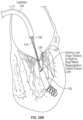
- FIG. 30 illustrates the suture loop exposed on the atrial side of the leaflet penetrating through the mitral leaflet to accept a loop-snare for capture of the suture loop and retrieval back through the catheter.
- FIG. 31 illustrates the suture loop closed around the suture loop and the suture being withdrawn proximally through the catheter.
- FIG. 32 illustrates the catheter to deliver a suture lock to the backside of the mitral leaflet as the suture is looped around the pathway including the distal apical anchor
- FIG. 33 illustrates a second catheter to contain the suture ends to deliver a suture lock over both leaflets locking the suture together after proper tensioning of the two ends.
- FIG. 34 illustrates the final position of the suture locks in position above and below the mitral leaflet and the suture ends cut to leave a final implant of a distal apical anchor connected to the mitral leaflet.
- FIG. 35 A illustrates attachment of a neo papillary muscle within the left ventricle.
- FIG. 35 B illustrates a steerable leaflet puncture catheter advancing through the mitral valve.
- FIG. 35 C illustrates the steerable leaflet puncture catheter deflected through an angle of at least about 180°.
- FIGS. 35 D through 35 G illustrate puncturing the leaflet and deployment of a collapsible pledget type leaflet anchor.
- FIG. 35 H illustrates a ventricle suture and a leaflet suture extending proximally through the deployment catheter.
- FIGS. 35 I- 1 through 35 I- 4 illustrate deployment of a T tag type leaflet anchor.
- FIGS. 35 J- 1 through 35 J- 3 illustrate deployment of a radially expandable tissue anchor.
- FIG. 35 K schematically illustrates a fulcrum positioned at about the proximal end of the neo papillary muscle.
- FIG. 35 L illustrates verifying mitral valve function prior to removal of the deployment system.
- FIG. 35 M illustrates the attachment of the leaflet suture to the ventricle suture following desired tensioning.
- FIG. 35 N illustrates severing of the leaflet suture and ventricle sutures, leaving the neo cord construct in place.
- FIG. 35 O illustrates a distal, steerable portion of a leaflet puncture catheter, having a compound deflected configuration.
- FIG. 36 A is a picture of a looped papillary muscle in a configuration it is first captured in.
- FIG. 36 B shows the looped papillary pulled up onto the chords in an area where a cutting step is preferably performed.
- FIG. 37 illustrates one embodiment of a chordae cutting tool.
- a method of transvascular prosthetic chordae tendinea implantation can comprise the steps of advancing a catheter into the left atrium, through the mitral valve, and into the left ventricle, and deploying a ventricular anchor from the catheter and into a wall of the left ventricle, leaving a ventricular suture attached to the ventricular anchor and extending proximally through the catheter.
- a leaflet anchor is deployed to secure a mitral valve leaflet to a leaflet suture, with the leaflet suture extending proximally through the catheter.
- the leaflet suture is secured to the ventricular suture to limit a range of travel of the leaflet in the direction of the left atrium.
- the deploying a leaflet anchor step may comprise securing the leaflet anchor to the leaflet within the range of from about 3 mm to about 10 mm from a leaflet coaptive edge.
- the deploying a ventricular anchor step may comprise attaching the anchor to the ventricular septum or the ventricle wall, preferably spaced apart from the apex.
- the deploying a ventricular anchor step may comprise advancing an anchor driver through the mitral valve, rotating the driver to secure the ventricular anchor, and proximally retracting the anchor driver to expose the ventricular suture carried by the ventricular anchor.
- the deploying a leaflet anchor step may comprise positioning a needle guide in contact with the leaflet and advancing a needle from the needle guide and through the leaflet.
- the method may further comprise deflecting a distal portion of the needle guide through an angle of at least about 160 degrees to position a distal end of the needle guide against the ventricle side of the leaflet.
- the needle guide may comprise a slotted tube and deflecting the needle guide may be accomplished by proximally retracting a pull wire.
- the securing step may comprise applying a suture lock to the ventricular suture and the leaflet suture.
- the method may further comprise applying tension to the leaflet suture prior to the securing step, to improve leaflet function.
- the method may further comprise applying sufficient tension to the leaflet suture to pull the limit of leaflet travel during systole to approximately to the level of the annulus.
- the securing step may comprise engaging a knot to secure the leaflet suture and the ventricular suture.
- the method may additionally comprise the step of cutting the leaflet suture and the ventricular suture proximally of the suture lock or knot, leaving the leaflet suture and the ventricular suture to function as a native chordae.
- the method may additionally comprise the initial step of identifying a patient including at least three characteristics selected from the group consisting of: the patient has been diagnosed with primary or degenerative mitral regurgitation; the patient has been diagnosed with secondary or functional Mitral Regurgitation; the patient has been diagnosed with Mixomotous Mitral Regurgitation; the patient has been diagnosed with a flail leaflet, ruptured chordae, or leaflet prolapse; the patient has Mitral regurgitation grade 1 or more; the patient has annular diameter from A2 leaflet to P2 leaflet at least 5 mm less than sum of length of P2+A2 leaflet; the patient has annular diameter from A2 to P2 leaflet of at least 10 mm; and the patient has an access vessel diameter of at least 2 mm.
- the patient may additionally have at least one characteristic selected from the group consisting of: the patient has been evaluated by a heart team including at least one cardiac surgeon and determined not to be an appropriate candidate for conventional open surgical repair; the patient has STS predicted operative mortality (STS Score) of 2 or greater; the patient was offered and refused open surgical repair; the patient is age between 18 and 90; the patient will not accept blood transfusion; the patient has had prior open chest surgery; and the patient has an ejection fraction of at least 10 percent.
- STS Score STS predicted operative mortality
- a method of increasing mitral valve leaflet coaptive area during systole comprises the steps of securing at least a first ventricular tension element to a wall of the ventricle and securing at least a first leaflet tension element to a mitral valve leaflet.
- the leaflet tension element is proximally retracted to move the limit of travel of the leaflet during systole in the direction of the ventricle, thereby increasing mitral valve leaflet coaptive area during systole.
- the leaflet tension element is thereafter secured to the ventricular tension element.
- the ventricular tension element may comprise a neo papillary muscle having a distal end facing the ventricular anchor, and a proximal end approximately at the height of the top of the native papillary muscle, and the securing step may comprise securing the leaflet tension element to the ventricular tension element at the proximal end of the neo papillary muscle.
- the neo papillary muscle may comprise an elongate, atraumatic body, and may comprise ePTFE.
- the securing a leaflet tension element step may comprise advancing a needle guide having a distal end through the mitral valve and into the left ventricle, and deflecting the needle guide through an angle of at least 160 degrees to place the distal end into contact with the leaflet during diastole.
- the method may further comprise advancing a leaflet anchor deployment needle out of the distal end of the needle guide and through the leaflet, and deploying an anchor from the needle.
- the deploying an anchor step may comprise deploying an anchor from a first, reduced cross section within the deployment needle, to a second, enlarged cross section for seating against the atrial side of the leaflet.
- the deploying an anchor step may comprise deploying a pledget.
- the proximally retracting the leaflet tension element step may comprise positioning an aperture in the left ventricle, with at least the leaflet tension element extending through the aperture, and proximally retracting the leaflet tension element with the aperture functioning as a fulcrum so that the tension element draws the leaflet in the direction of the ventricle.
- the fulcrum may comprise a distal opening of a catheter and the proximally retracting step may comprise proximally retracting the leaflet tension element through the catheter.
- the method may further comprise securing a second leaflet tension element to the leaflet and to the ventricular tension element.
- an assembled in situ mitral valve leaflet restraint comprising an elongate, flexible neo papillary muscle, having a proximal end and a distal end, and a helical tissue anchor attached to the distal end of the neo papillary muscle.
- An elongate, flexible neo chordae extends proximally from the neo papillary muscle, and a leaflet anchor is attached to a proximal end of the neo chordae.
- the leaflet anchor is enlargeable from a first reduced cross section for advancing through the leaflet, to a second, enlarged cross section for contacting an atrial side of the leaflet.
- the neo chordae may be attached to a suture extending distally through the neo papillary muscle to the helical tissue anchor.
- An embodiment to attach a ruptured or flail chord could include a catheter delivered through the femoral vein and traversed up into the IVC and trans-septal to the left atrium where an attachment is made to the mitral annulus.
- This attachment could be a single suture loop through the mitral annular tissue or an anchor inserted into the annulus either rotated, pierced into or threaded to the local tissue where the mitral leaflet meets the atrial tissue at or near the mitral annulus.
- the anchor could be constructed of a coiled-wire anchor which would be rotated into the tissue with a suture receiver for chordal replacement or a pre-attached chordal affixed to the anchor.
- a connection to the mitral annulus can provide a secure and positive attachment point as a stable anchor through a piercing, hook or corkscrew anchoring device.
- a chord can be connected to drape over the mitral valve leaflet and further attached or anchor into the apex of the left ventricle. It could also be pierced through the anterior or posterior mitral leaflets at any position.
- the chord can be made of round, flat PTFE, PE or nylon as conventionally used in surgery for chordal repair.
- Anchoring to the annulus can provide an attachment point which is positive and immobile with respect to the mitral leaflets which are difficult to capture with a ruptured chord due to the movement at each heartbeat. This movement can be halted with a grasping of the flail leaflet by a mechanical gripper tool, suction tube or a cryo-catheter to freeze-grab the leaflet.
- the upper anchor As the upper anchor is positively attached to the mitral annulus it can be draped over the mitral leaflet and between the existing chords to limit the location laterally with respect to the leaflet. Locating the leaflet between existing chords provides the artificial chord a positive anchor at the upper anchor point, a secured angular location passing through the existing chords and another positive location at the apex of the left ventricle.
- the replacement chord can be a single suture strand or a plurality of chords traversing up and down the pathway as described above allowing the load to be carried by a plurality of chords.
- the lower apical anchor located in the left ventricle can be secured via rotational screw or plug to hold positively.
- the anchor could be short in height and close to the base of the apex or have an extended length to better match the native papillary muscles of about 20-22 millimeters above the apex of the left ventricle.
- a single or plurality chord could be attached to one or more anchors at the base of the left ventricle.
- the anchor could be constructed of an implantable grade of stainless steel, Nitinol or other metallic material that would be visible on fluoroscopy or a polymeric material such as PEEK, PTFE or other implantable materials. These polymers could be doped with a radiopaque marker for visibility if needed.
- An embodiment for the anchoring system could comprise of the apical tissue anchor which couples or attaches to the left ventricle, a riser which projects the attachment from the apical tissue anchor and could be constructed from a monolithic material or a combination of materials including polymers and metallic components.
- the construction could be rigid throughout or have flexible joints to allow movement or an elastic zone or zones for controlled motion and flexibility. It could be constructed of a round crossing profile or any other profile including a varying shape longitudinally.
- the diameter could be about 6 to 24 French (2 to 8 millimeters) and length about 20 to 40 millimeters and delivered via steerable catheter with or without a guidewire generally along the central axis.
- a tension force would allow for an adjustment under live echo while monitoring the leaflet motions and regurigtent flow reduction.
- the final step could be to tension, lock and disconnect the chord from the delivery system.
- a tension of the chord would apply tension to the connected mitral valve leaflet strain relief and a locking device such as a Cor-Knot from LSI Solutions could be advanced down the chord and lastly the suture tail could be cut.
- the steps of the replacement chord delivery could include:
- the delivery could be in a somewhat opposite order:
- FIG. 1 illustrates the mitral valve annulus 16 with the suture 22 attached as delivered via the catheter 100 .
- FIG. 2 illustrates the distal anchor 32 being delivered via the catheter 100 and attached to the suture 22 further connected to the mitral annulus 16 .
- FIG. 3 illustrates the distal anchor 32 being rotated into the apex 20 of the heart with suture lines 22 attached for later attachment to the mitral leaflet 24 or the mitral annulus 16 .
- FIG. 4 illustrates the distal anchor 32 rotated into the apex 20 of the heart with suture lines 22 attached to the mitral leaflet 24 or the mitral annulus 17 .
- FIG. 1 illustrates the mitral valve annulus 16 with the suture 22 attached as delivered via the catheter 100 .
- FIG. 2 illustrates the distal anchor 32 being delivered via the catheter 100 and attached to the suture 22 further connected to the mitral annulus 16 .
- FIG. 3 illustrates the distal anchor 32 being rotated into the apex 20 of the heart with suture lines 22 attached for
- FIG. 5 illustrates the distal anchor 32 attached and projected above the apex 20 of the heart approximately the same height as the top of the papillary muscles.
- the anchor 32 can include a riser 70 connected to a connection point 72 having a length of about 20-40 mm in certain embodiments.
- FIG. 6 illustrates the distal anchor 32 attached and projected above the apex 20 of the heart approximately the same height as the top of the papillary muscles and attached to the mitral annulus 16 and or mitral leaflet 24 .
- FIG. 7 illustrates the distal anchor 32 attached and projected above the apex 20 of the heart approximately the same height as the top of the papillary muscles and attached to a suture 33 in a form of a loop traversing through the catheter 100 .
- FIG. 8 illustrates an embodiment in which a catheter delivered suture 50 in a form of a loop can be pierced through the mitral leaflet 24 with a strain relief 52 on the ventricular side of the mitral leaflet 24 and a distal anchor 32 in the bottom of the left ventricle with the final suture tension adjustment being held with a suture lock 54 advanced over the suture tails 56 .
- FIG. 9 illustrates an embodiment in which a catheter delivered suture line or loop 60 can be pierced through the mitral leaflet 24 with a strain relief 52 on the ventricular side of the mitral leaflet 24 .
- a suture lock 62 can be advanced to the atrial side of the mitral leaflet 24 to secure the suture tail before cutting of the suture 60
- FIG. 10 illustrates an embodiment in which a catheter delivered suture line 60 can be pierced through the mitral leaflet 25 with a strain relief 52 on the ventricular side of the mitral leaflet 25 and a suture lock 62 advanced to the atrial side of the mitral leaflet to secure the suture tail.
- the other end of the suture tail extends from the catheter handle through the catheter 100 traversing about the distal anchor 32 located in the bottom of the left ventricle for tensioning of the suture.
- a second suture lock 63 can be advanced over the final suture tail once the suture tension is adjusted by the user.
- FIG. 11 illustrates an embodiment in which a catheter delivered suture loop 60 can be pierced with a piercing element 27 (e.g., a needle) through the mitral leaflet with a strain relief on the ventricular side of the mitral leaflet 24 in a looped configuration about the strain relief 52 and a distal anchor 32 in the bottom of the left ventricle with the final suture tension adjustment being held with a suture lock advanced over the suture tails. Holding the leaflet steady and counteracting the piercing force of the strain relief can be accomplished using a cryo-catheter 70 sticking to the mitral leaflet 24 .
- a piercing element 27 e.g., a needle
- FIG. 12 illustrates a catheter delivered suture loop 60 pierced through the mitral leaflet 24 with a strain relief to be delivered on the ventricular side of the mitral leaflet in a looped configuration about the strain relief and a distal anchor 32 in the bottom of the left ventricle with the final suture tension adjustment being held with a suture lock advanced over the suture tails. Holding the leaflet steady and counteracting the piercing force of the strain relief is illustrated a cryo-catheter 70 sticking to the mitral leaflet.
- FIGS. 13 and 14 illustrates a views from the atrial side showing where according to certain embodiments the mitral annulus 16 is pierced and where the distal anchor 32 is located with respect to the native papillary muscles
- FIG. 15 illustrates a variety of anchors embodiments 32 a , 32 b , 32 c , 32 d , for attachment into the apex of the left ventricle including coiled round wire 32 a , 32 b , 32 c and laser cut hypo-tube 32 b with vertical risers 70 adjusting the connection point 72 closer to the height of the papillary muscles to better simulate the correct angle and match the new chordal connections.
- the anchor 32 c includes a riser 70 in th form of a strut and the connection point 72 that can receive the suture 60 , which can be secured within the connection point 72 by a silicone plug 74 .
- FIGS. 16 - 22 illustrate another method according to certain embodiments.
- FIG. 16 illustrates a trans-septal catheter delivering an anchor 32 in the apex 20 of the left ventricle with a plurality of replacement chords 22 attached and extending out the handle of the catheter 100 .
- FIG. 17 illustrates the trans-septal catheter 100 o of FIG. 16 delivering a piercing tool 80 through the mitral leaflet 24 to deliver a strain relief anchor connected to a suture loop 60 .
- FIG. 18 illustrates the trans-septal catheter 100 delivering a suture loop 60 through the mitral leaflet 24 piercing through the leaflet 24 with the suture loop 24 .
- FIG. 16 illustrates a trans-septal catheter delivering an anchor 32 in the apex 20 of the left ventricle with a plurality of replacement chords 22 attached and extending out the handle of the catheter 100 .
- FIG. 17 illustrates the trans-septal catheter 100 o of FIG. 16 delivering
- FIG. 19 illustrates the trans-septal catheter 100 delivering the strain relief to the ventricle side of the mitral leaflet 24 exposing it for delivery through or with the piercing tool 80 .
- FIG. 20 illustrates the trans-septal catheter delivering the strain relief 52 and the piercing tool 80 being withdrawn from the mitral leaflet 24 .
- FIG. 21 illustrates the trans-septal catheter 100 delivering the strain relief 52 with the connection to the distal anchor 32 and the suture loop 60 extending back out the catheter handle FIG.
- FIG. 22 illustrates the trans-septal catheter delivering a suture lock 62 to the distal anchor 32 being advanced over the suture tail while tension is applied from the proximal end of the suture back our the catheter handle to adjust the position and tension of the final implant suture connected now to the mitral leaflet and the distal apex anchor.
- FIG. 23 illustrates an embodiment in which a final suture loop anchoring embodiment in which the distal apex anchor 32 to the mitral leaflet 24 noting the mitral anchor or strain relieve element 52 can be double sided flange 52 b or a single side flange 52 a as shown in the unexploded view
- FIG. 24 illustrates an embodiment in which a continuous loop anchor 90 delivered in its final position with a distal apex anchor 32 and a strain relief element 52 on the mitral leaflet 24 .
- FIG. 25 illustrates an example of a distal apex anchor 32 constructed of a stainless tube 73 and a silicone anchor plug 72 //to limit the suture movement before delivery of the suture lock 62 for final positioning.
- the materials can be varied and changed to accommodate size and material enhancements
- FIGS. 26 - 34 illustrate an embodiment in which order of the placement distal apex anchor 32 can be modified.
- FIG. 26 shows a catheter 100 penetrating the septum 12 from the right atrial and the left atrium 14 .
- FIG. 27 illustrates an anchor 32 being rotated into the left ventricle.
- FIG. 28 illustrates the distal apical anchor 32 in place with the suture lines 22 attached and extending back through the catheter 100 and an extension arm 94 exposed to capture the mitral leaflet 24 with a needle to be fired when properly positioned on the leaflet 24 .
- FIG. 26 shows a catheter 100 penetrating the septum 12 from the right atrial and the left atrium 14 .
- FIG. 27 illustrates an anchor 32 being rotated into the left ventricle.
- FIG. 28 illustrates the distal apical anchor 32 in place with the suture lines 22 attached and extending back through the catheter 100 and an extension arm 94 exposed to capture the mitral leaflet 24 with a needle to be fired when properly
- FIG. 29 illustrates the extension arm 94 in contact with the mitral leaflet 24 and the needle 96 connected to a suture loop 60 penetrating the leaflet 24 to expose a suture loop 60 on the atrial side of the mitral leaflet 24 .
- FIG. 30 illustrates the suture loop 60 exposed on the atrial side of the leaflet penetrating through the mitral leaflet to accept a loop-snare 99 for capture of the suture loop 60 and retrieval back through the catheter 100 .
- FIG. 31 illustrates the suture loop snare 99 closed around the suture loop 60 and the suture being withdrawn proximally through the catheter 100 .
- FIG. 32 illustrates the catheter 100 delivering a suture lock 62 to the backside of the mitral leaflet as the suture is looped around the pathway including the distal apical anchor 32 .
- FIG. 33 illustrates a second catheter 101 to contain the suture ends to deliver a suture lock over both leaflets locking the suture together after proper tensioning of the two ends.
- FIG. 34 illustrates the final position of the suture locks 62 in position above and below the mitral leaflet 35 and the suture ends cut to leave a final implant of a distal apical anchor connected to the mitral leaflet 24 .
- Chordal end termination and suture locking configurations and devices can include a one or more of knots, pledgets or other termination techniques to reduce the focal stress at the attachment points.
- Piercing through annular tissue and leaflets can be achieved via sharpened needle insertion and driven via steerable catheter and core shaft to push, locate and drive the needle through the mitral leaflet as guided under fluoroscopy or echo guidance.
- Leaflet location and isolation can be achieved by a mechanical technique of grasping or pinching the leaflet or by suction or freeze-grabbing with a cryo-catheter. These techniques would include a cryo-catheter used in ablation procedures to freeze the focal tissue as described, for example, with reference to FIG. 12 .
- cryoablation-catheters used for atrial fibrillation often attach themselves to the mitral leaflets accidentally and need to be deactivated to release the attached leaflets. This same cryo attachment could be used to locate and isolate the leaflet in question for a reinstallation of the repair.
- the cryo catheter uses a gaseous exchange (NO or Argon) to drop the temperature of the tip of the catheter to as low as minus 75 degrees Celsius.
- the lower apical anchor construction could consist of a coiled distal section to rotate into the apex of the left ventricle with a round or flat wire construction or a laser cut tube emulating a cork screw similar to a wine cork as described for example in FIG. 6 and FIG. 15 .
- a variable pitch in the screw will allow for a more secure attachment into the surrounding tissue.
- Another device for tissue securement could include a swaging or ovalization of the screw anchor to achieve the same securement.
- the attachment to the anchor riser could be pinned, welded, or joined though other mechanical devices. Alternatively it could be constructed of the same material and laser cut from the same tube of stainless steel, Nitinol or other implantable material.
- At the proximal most end could be a loop or tube to receive the replacement chord such as illustrated in the connection 72 of FIG. 15 or a plurality replacement chords could be preloaded ready for delivery and extending out the handle of the catheter.
- the distal anchor could be delivered to the apex of the left ventricle with a plurality of replacement chords looped to the anchor and the extending back to most proximal handle section of the catheter.
- a delivery piercing element or tube can be advanced to the mitral leaflet to pierce through and deliver a pledget or restraining element through and to the back side (ventricular side) of the leaflet.
- a locking element to hold the position of the chord and pledget securely to the leaflet position. Once delivered this free end can be cut. Finding and holding the leaflet can be achieved by the cryo-catheter to hold the leaflet from the atrial side or a gripping tool to grasp the leaflet from the free edge could also be used.
- the first piercing and pledget is delivered the other free end now can be tensioned around the distal apex anchor and a second locking element can be delivered to hold position relative to the end of the apex anchor.
- chord or suture anchor can be secured by an interference fit to the distal apex anchor and or to the other chord line running up to the mitral leaflet. Its important to note the drawings illustrate the delivery and installation of the mitral leaflet anchor to the posterior leaflet but anchors and replacement chords could also be to delivered to the anterior leaflet or any position on the mitral leaflet including the free margin, coaptation zone, or annulus.
- Another method would be to place the distal rotational anchor in the left ventricle that is connected to a continuous loop of suture similar to a rubber band.
- One end would be secured to the distal anchor and the other end would pierce the mitral valve leaflet and connected to a strain relief element to distribute the force on the ventricular side of the mitral leaflet from pulling the replacement chord through or tearing the leaflet.
- the strain relief element could be a laser cut tube that expands from a small configuration to a larger configuration once passed through the leaflet either through a compressive axial force or be constructed of a memory metal like Nitinol where it is pre-set to a shape where the delivery diameter is small and the delivered diameter expands to a larger state.
- the delivered diameter could be about 0.5 millimeters expanding into about 2-3 millimeters in diameter and have a length of about 2 to 5 millimeters at delivery shortening to about 1-2 millimeters. It could also be constructed of memory metal and set to a round shape similar to an Amplatz device or a simple or complex suture knot located on the ventricular side of the leaflet. Another configuration could be a wound looped Nitinol wire that would look like a daisy with Nitinol wire peddles. This device could also be used to adjust the final length of the loop chord by winding or coiling the loop end passed through the leaflet. This winding mechanism could also be located at the distal coil anchor located in the left ventricle.
- the adjustment could be actuated during delivery to adjust the chord length and or post procedure where the adjustment is accessed and either shortened or lengthened.
- a rotational ratcheted drive coupled to a drive shaft or wire could be rotated external to the body by coupling and decoupling when adjustment is needed.
- the drive shaft could be a round wire constructed of stainless or Nitinol where a hex coupling interface between the drive shaft and winding mechanism could be used to engage and disengage the two elements.
- the two could be delivered mated to one another for actuation and could later couple by using a loop snare to grasp the winding mechanism and couple the drive shaft engaging the hex drive device.
- the winding mechanism could utilize a simple rotational spool with a cog-style stop for anti-rotation or a friction resistance to hold the tensioned position.
- designing the distal coil anchor to accept an inner matching pitch adjustment screw, which would be coupled to the chord and allow for the outer body of the distal anchor to be driven into the apical tissue and secondarily a rotation of the inner matching pitch screw would allow for a tensioning of the chord by shortening the relative distance between the two screw elements.
- the simplest configuration would be a coil inside another coil where they both have right or left-hand threading and would couple with one another to provide a rotational motion into a translational or axial motion. Locking the two coils together post adjustment would provide for a positive location of the chord length between the leaflet and the distal anchor system.
- the method of treating a patient begins with selecting an appropriate patient.
- the patient includes at least one three or five of the following characteristics from a first group:
- Annular diameter from A2 leaflet to P2 leaflet at least 5, 10, 15, 20, 30, 50 mm less than sum of length of P2+A2 leaflet. Or similar mathematical relationships that ensure adequate redundant coaptation after repair, so as to create a durable repair.
- Access vessel diameter at least 2-10 mm diameter
- the patient has at least 1, 3, 5 of the following characteristics from a second group:
- a heart team including at least one and preferably two cardiac surgeons and determined not to be an appropriate candidate for conventional open surgical repair.
- STS predicted operative mortality (STS Score) of 2-20 or greater
- Age between 18 and 90, or preferably between 35 and 85 more preferably between 40 and 85.
- the patient selected meets at least 1, 2 or 3 criteria from group and at least 1, 2 or 3 from the second group. In one embodiment the patient selected meets at least 1, 2 or 3 criteria from group and at least 1, 2 or 3 from the second group and does not meet at least 1, 2 or 3 from the third group.
- Patients can be screened using echocardiographic imaging and or CT imaging.
- MRI imaging is also possible.
- a contrast gated cardiac CT with at least 32, 64, 128 slices is obtained prior to the procedure and used for patient selection and or case planning.
- imaging software the annular diameter is measured from the hinge point of A2 to hinge point of P2 leaflet, and the free length of the leaflet is measured. These measurements are compared to ensure that after the procedure is completed sufficient redundant coaptation will be present to produce a durable repair.
- the annular dimension is reduced using another device or method such as a trans-catheter annuloplasty device, to create a small enough annular diameter.
- the present disclosure has the potential to allow excellent real time assessment and adjustment of suture placement and tension during the procedure.
- Some embodiments of the imaging method offer significant advantages in visualization even compared to what is available during open cardiac surgery.
- the surgeon's initial assessment step involves filling the ventricle with saline to push the mitral leaflets closed and visually asses areas of leakage, prolapse or inadequate coaptation.
- This assessment is limited because it is not performed on a beating heart, but the sutures are tied off and secured based on this assessment, then the atrium is closed the heart is reanimated, and the final echo assessment on the beating heart is performed. If an issue is identified, the surgeon needs to stop the heart again, reopen the atrium and modify the previously completed repair. Because the sutures are knotted and trimmed they cannot simply be re-tensioned and so are typically replaced or additional artificial chords added. In some embodiments of the present disclosure real time echocardiographic assessment is possible as the suture tensions are being adjusted individually.
- the method for implanting the artificial chords includes the following steps; first securing one end of a plurality of artificial chord to a leaflet of the mitral valve or annulus of the surrounding tissue and the other end to an anchor point mechanically connected to the left ventricle; Second adjusting the tension of the artificial chords while viewing an echocardiographic image of the mitral valve.
- the echocardiographic image includes color Doppler assessment of velocity and or flow.
- the echocardiographic image includes real time 3d or 4D echo.
- the color flow Doppler and 3D images are fused or combined.
- the Echo probe is placed through the patient's esophagus in some embodiments the echo probe is a surface probe on the patient's chest, and in some embodiments the echo probe is within the patient's vascular system.
- At least 1, 2, 3, 4, 5 of the functions below are confirmed under echocardiography as the artificial chords are being tensioned, in another embodiment after the artificial chords are tensioned but before the chords are permanently disconnected from the delivery system, where this may allow simplified re-tensioning if necessary.
- a minimum leaflet coaptation distance of at least 3, 5, 9, 12, 15 mm is achieved throughout the line of coaptation
- the physician or team decides to make the results permanent or to readjust the tension, add additional repair components or abort the procedure.
- the physician also has the option to remove the entire implant, in other embodiments the physician has the option to remove the artificial chord portion of the implant but the ventricular anchor remains implanted.
- the assessment step is further augmented by including a stress echo component where drugs such as pressures are given to the patient to adjust the heart rate, cardiac output and ventricular pressure to further assess how the repair functions in different hemodynamic conditions.
- the patient is preferably under conscious sedation. This makes Trans Esophageal Echocardiography more challenging, but minimizes anesthesia risk and allows patients to go home more quickly.
- standard cath lab monitoring procedures should be performed including arterial pressure, EkG ACT blood gasses etc. Additionally wedge pressure or Left atrial pressure may be useful for this procedure.
- careful monitoring of arterial pressure provides an early indicator of damage to the mitral valve apparatus, entanglement of the device in Chordae, or damage to the septal wall. Measuring left atrial pressure may provide a simple quantifiable measure of improvement in mitral function without the challenges associated with getting the appropriate echocardiographic view.
- a blood vessel is accessed through conventional methods standard in interventional cardiology, preferably the vessel is a vein.
- the vessel is the femoral vein, in another embodiment the vessel is the radial brachial or subclavian vein. Access may be by cut-down or percutaneous needle stick.
- the vessel is prepared for closure by pre-insertion of a vascular closure device such as Percolse or Prostar (Abbot Vascular)
- a guidewire is advanced, optionally using a guide catheter, through a valve into the right ventricle.
- the device of the present disclosure can be advanced over the guidewire to a position near the apex of the ventricle.
- a sharp curve is created at the tip of the device.
- the curve is oriented so that the exit lumen points towards the septal wall of the heart.
- the radius of curvature of the fully curved system is preferably less than 3-30 mm, and the curvature is preferably positioned less than 5-50 mm from the tip of the system.
- this curve is created using a steerable catheter.
- the preferred embodiment of a steerable catheter incorporates a pull wire that when pulled creates the inner radius of the catheter.
- Some embodiments also include a coil a braid and or an axial reinforcement.
- the curve is created using coaxial sheaths with different shapes. For example an outer sheath substantially straight or with a large radius of curvature near its tip combined with an inner sheath with a small radius of curvature at its distal tip. By advancing the inner sheath out of the outer sheath the tip of the catheter creates the desired curve. By advancing the more curved sheath further a greater curved angle is obtained.
- the sheaths have different relative stiffness' s at different points in their length.
- the outer sheath is curved to access the apex of the ventricle and stabilize through the vena cava, the shape that enables this is 7 to 50 cm back from the distal tip of the sheath.
- the inner sheath is substantially more flexible (less than 30, 50, 70, 90% the bending stiffness by ASTM three point bend test) than the outer sheath in the range 7 to 55 cm from its distal tip, this enables the inner sheath to move relative to the outer sheath without substantially changing the orientation of the outer sheath in the heart and vena cava.
- the distal portion of the inner sheath is preferably stiffer than the previously described section, and stiff enough that as it is extended out of the outer sheath it assumes its approximate shape despite contact with the structures of the heart.
- the device is oriented so that the exit of the catheter is near the Right ventricular apex, pointing into the septal wall and preferably upwards towards the mitral valve.
- the position of the sheath is confirmed by imaging.
- a four chamber echocardiaographic view is used in some embodiments, a short axis mitral view is used in other embodiments. Fluoroscopic imaging is used in some embodiments.
- the desired puncture site can be selected and the appropriate angle based on the planned orientation of the replacement chords.
- a puncture higher up closer to the papillary muscle insertions and away from the ventricular apex is preferred, this location provides the benefit that as the heart remodels and the ventricular volume is reduces to more normal physiological levels the tension in the chords will change less than with a near apical attachment.
- a needle and or dilator is advanced through the sheath or sheaths and through the septal wall of the heart.
- a needle and dilator are used together. Both the needle and dilator are pre-shaped with curvature near their distal tip to ensure the needle stays within the left ventricle and avoids the mitral valve apparatus. Presence of the needle in he left ventricle may be confirmed with echocardiography, fluoroscopy and or by the presence of red (oxygenated) pulsatile blood at the proximal end of the needle.
- a guidewire is advanced across the septum.
- the guidewire is further advanced across the mitral valve into the atrium, and in some embodiments further into a pulmonary vein.
- the wire is confirmed not to be tangled in the mitral apparatus using echocardiography and wire manipulation.
- a device such as a balloon or sheath is advanced over the wire to confirm the wire does not pass through the chordal structure.
- the present disclosure include several embodiments of ventricular anchors.
- the ventricular anchor is similar to an Amplatz septal occluder (ST Jude Medical) consisting of a braided section that expands on both sides of the septal wall.
- ST Jude Medical an Amplatz septal occluder
- the anchor is a barbed stent-like structure intended to be deployed within the ventricular wall.
- the stent structure may be self-expanding or mechanically ie balloon expandable and may include barbed anchors similar to those found on stent grafts such as Endurant (Medtronic)
- the anchor is a flanged covered stent where the Right ventricular side opens into a substantially flat configuration oriented in a plane substantially perpendicular to the axis of the stent.
- the Flange is constructed from a ring around the circumference of the flange and the flange itself a layer of fabric.
- the flange can be collapsed into an elliptical shape and delivered through the lumen.
- the ring may be constructed from nitinol titanium stainless steel or a cobalt chrome alloy.
- a fabric lumen extends through the center of the flange and into the trans-septal puncture. After chord implantation tension to snug the flange against the septal wall is provided through the chords in some embodiments. During the procedure a portion of the delivery system can be used to push the flange against the septal wall.
- the fabric sleeve incorporates and anchor such as a stent or a barb to stabilize it within the septal wall.
- the ventricular anchor is deployed over a guidewire. After the anchor is deployed the chord delivery anchors and their delivery system can be delivered through the ventricular anchor and over the guidewire.
- Identifying the correct place to place the new chords is performed substantially using echocardiography.
- the area of a regurgitant jet or a leaflet prolapse or flail can be identified using 2d or 3d echo and or color flow Doppler. Preferably a combination of these imaging modalities is used.
- the device to deliver the chords is advanced across the septal puncture.
- the same steerable or shapeable system used to create the septal puncture is advanced across the puncture.
- it is a separate device that can pass through the other sheaths.
- the position of the distal tip of the device can be oriented relative to the mitral structure as follows. Biased more anterior by increasing the curvature of the system where it passes into the Left ventricle through the septum. Biased more posterior by decreasing the curvature of the system where it passes into the Left ventricle through the septum. Biased from commissure to commissure by rotating the curved portion that passes through the sheath. Biased atrially by extending or ventricularly by retracting the distal portion of the device.
- the bulky knot system used by Harpoon Medical is used in one embodiment.
- the looped suture used by Neochord Inc is used in another embodiment. Both these methods appear to work well in early clinical experience.
- the preferred embodiments intend to replicate the clinically proven suture tissue interfaces that have been developed in the open surgical experience.
- Another embodiment may use a bifurcated catheter.
- One side of the catheter engages under the leaflet this side can be pushed on to help identify the area of the leaflet where the suture will pass.
- the other side passes into the atrium.
- a needle or pair of needles puncture the leaflet from the first side of the catheter and a snare captures the needles or the suture from the needles from the second side of the catheter.
- a loop end of the suture is passed over the snare such that when the needle end of the suture is pulled back through it forms a girth hitch.
- the loop end of the suture is twisted and doubled over twice forming a knot known a prusik or double girth hitch.
- the bifurcated catheter method is appropriate for replacing secondary chords with a minor adaptation to allow the snare side to puncture the leaflet.
- a series of suture loops are created encircling the entire annulus.
- suture loops are created only in a safe area away from the aortic valve, coronary arteries and conduction pathways.
- the suture loops are created in the areas where the heart is most likely to dilate, ie in an area of prior infarct, or in an area near the mitral commissures.
- the result may be assessed. Tension is applied selectively on each artificial chord until the desired leaflet motion is achieved. Preferably a target coaptation height is achieved by echocardiography. In some embodiments, as too much and too little tension are balanced the sutures are slightly over tensioned to allow some remodeling to occur.
- the sutures are knotted on the right ventricular side of the anchor using a crimpable knot large enough to prevent the crimped knot from passing through an opening in the anchor.
- the artificial cords are crimped directly to a suture-sewn or tied to the anchor.
- the artificial chord tension can be adjusted in a similar procedure. In the preferred embodiment this can be achieved entirely from the right ventricle without re-crossing the septum.
- the crimpable knots are snared, pulled away from their base and twisted. The twisting motion of the suture of pair of sutures forming the artificial chord effectively shortens it.
- the crimp knot is snared, pulled and additional crimp knot placed over it.
- the anchoring location is at the papillary muscle.
- the suture attachment to the papillary muscle or ventricular wall is made by creating a figure of eight suture, as is commonly done by surgeons during open chordal replacement.
- This type of anchor can be placed by a trans-catheter method through the trans-septal ventricular puncture described above, or can be placed through a more conventional atrial trans-septal puncture.
- One embodiment of the system as adapted to suture to papillary muscles is a simple change to the bifurcated leaflet suturing system where the needle and snare ends are curved inward towards each other so that when actuated they can place a suture through a papilay muscle.
- the ventricular anchor is a cork screw shaped anchor similar to an Aptos Endovascular staple (Medtronic Inc) or any of the configurations used to secure pacemaker leads.
- the ventricular anchor is retrievable.
- One example is a recapturable self-expanding stent, or an Amplatz like device.
- artificial chords are retrievable through a hemodynamic assessment period. In one embodiment this is achieved by pulling both ends of the suture for assessment, prior to engaging the girth hitch for permanent implantation
- the procedure is performed in conjunction with another mitral valve repair procedure.
- This simulates the multiple techniques typically used by surgeons.
- annuloplasty rings such as cardiac dimension coronary sinus based approach, Mitralign and Valtech suture based approaches etc.
- Mitraclip (Abbott) simulates an Alfieri stitch, a seldom used surgical technique that creates two orifices.
- the preferred embodiment of the device includes and outer sheath that is curved to engage the shape of the vena cava and right ventricle.
- the proximal end of the outer sheath is connected to the handle of the delivery system.
- a conventional dilator for gaining vascular access.
- the dilator is changed out for a special trans ventricular dilator, with a relatively flexible proximal portion and a stiffer sharply curved distal portion with a short tapered radio opaque tip.
- the handle has a provision to lock to the dilator preventing both axial and rotational movement.
- the ID of the dilator allows clearance for a long flexible, preferably hollow needle.
- the needle is curved.
- the needle is configured to allow the needle tip to be advanced through the distal tip of the dilator and precisely place the trans-ventricular puncture.
- the needle is sized to accommodate a 0.009, 0.014, 0.018, or 0.035 inch diameter guidewire.
- the dilator is advanced through the puncture over the needle and the needle withdrawn.
- the needle is integral to the dilator and can be retracted within the dilator or extended a limited length past the tip of the dilator, in some embodiments the length is 2 to 20 mm in other embodiments 4 to 40 mm.
- catheter 100 has entered the left atrium 102 via conventional techniques.
- Catheter 100 is advanced through the mitral valve 104 to the vicinity of the apex 112 of left ventricle 106 .
- a tissue anchor 108 such as a helical tissue anchor 110 is rotated into the muscular wall by an anchor driver (not shown) advanced distally through catheter 100 .
- the catheter 100 and/or anchor driver is proximally retracted to leave the anchor 110 secured to the wall, and attached to an anchor suture 114 which extends proximally throughout the length of the catheter 100 .
- a distal portion of the anchor suture 114 may carry a neo papillary muscle 116 which may comprise a soft ribbon or body 118 , optionally approximating the size of a mitral papillary muscle.
- the anchor 108 is attached at a point that is offset from the thin tissue of the apex 112 , and is instead implanted in the generally thicker adjacent wall of the ventricle. Positioning the anchor is preferably also such that the longitudinal axis of the implanted neo chord construct is aligned approximately parallel to or concentric with the original path of the native chord.
- a steerable leaflet capture catheter 120 is advanced distally beyond the catheter 100 , through the mitral valve 104 and into the left ventricle 106 .
- a distal portion of leaflet capture catheter 120 is provided with a deflection zone 122 .
- Deflection zone 122 may comprise any of a variety of deflection mechanisms.
- a plurality of transverse slots 124 may be spaced apart along a first side of the catheter 120 .
- a second, opposing side 126 of the catheter comprises an axially incompressible spine. Proximal retraction of one or more pull wires (not shown) causes axial collapse of the slots 124 , thereby deflecting the catheter as shown, for example, in FIG. 35 C .
- the deflection zone 122 may be deflected throughout an angle of at least about 160° and preferably at least about 180° or about 190° or more in a simple or compound curve, and have a best fit radius of curvature of less than about 2 cm, and, preferably, less than about 1 cm.
- the shortest linear distance D between the distal tip 128 and the catheter shaft is within the range of from about 0.5 cm and about 1.5 cm and optimally approximately 1 cm, to position the leaflet anchor a desired setback from the leaflet coaptive edge.
- the steerable leaflet capture catheter 120 is advanced through the mitral valve 104 and deflected as illustrated in FIG. 35 C to position distal tip 128 in contact with a ventricular side 130 of a flail leaflet 132 .
- a control on a proximal manifold may be manipulated to advance a needle 134 out of the distal end 128 and through the flail leaflet 132 . Puncture of leaflet 132 by needle 134 may be accomplished during diastole, when the leaflet 132 is biased in the direction of the left ventricle 106 .
- the catheter 120 and/or needle 134 may be utilized to deploy any of a variety of tissue anchors to secure a suture to leaflet 132 .
- a pledget 136 carried by a leaflet anchor suture 138 is deployed from the needle 134 on the atrium side of the leaflet 132 .
- the pledget is in the form of an elongate ribbon, having a proximal end and a distal end. The distal end is secured with respect to the leaflet anchor suture 138 .
- the leaflet anchor suture 138 may be threaded through one or two or four or more apertures in the elongated ribbon. As seen in FIGS.
- proximal retraction on the leaflet anchor suture 138 causes the ribbon to fold and collapse axially, thereby forming a mass of sufficient transverse area that proximal tension on the leaflet suture is insufficient to pull the resulting pledget through the leaflet.
- the leaflet capture catheter 120 is thereafter proximally retracted, leaving the construct as illustrated in FIG. 35 H .
- leaflet anchors may be utilized, generally sharing the characteristic of being laterally enlargeable from a low crossing profile for crossing the leaflet, to a larger transverse profile for resisting retraction back through the leaflet. Lateral enlargement may be accomplished by tilting a T anchor or by active deformation by a control wire or elastic deformation following release from a constraint.
- FIGS. 35 I- 1 through 35 I- 4 illustrate deployment of a T tag type anchor through the flail leaflet 132 .
- An anchor element such as a single T tag bar 140 secured to suture 138 may be distally advanced through the needle 134 by a push wire 142 .
- Push wire 142 may be provided with a distal pushing platform 144 , which may be provided with a cut out 146 for accommodating suture 138 .
- the bar 140 may comprise a single element as illustrated, or an “X” or multi strut construct, depending upon desired performance characteristics.
- FIGS. 35 J- 1 through 35 J- 3 An alternative leaflet anchor is illustrated in the sequence of FIGS. 35 J- 1 through 35 J- 3 .
- the tissue anchor comprises a hub 150 secured to the suture 138 .
- Hub 150 carries a plurality of spokes 152 which are enlargeable transversely from a low profile linear configuration when constrained within needle 134 , to an expanded configuration illustrated in FIG. 35 J- 3 for resisting proximal retraction through the leaflet 132 .
- At least two, and preferably four or six or more spokes or struts 152 may be provided, extending radially outwardly from the hub 150 in the deployed configuration, for providing a footprint against the leaflet.
- the struts may be inclined radially outwardly in the proximal direction to provide a force damper allowing hub 150 to be transiently drawn closer to leaflet 132 in response to tension spikes such as when the leaflet 132 reaches the limit of travel during systole imposed by the implanted neo chord.
- the spokes 152 and hub 150 may be laser cut from a NiTi tube and adhesively bonded, crimped, or otherwise attached to the leaflet suture 138 .
- a fulcrum 154 is positioned at about the distal end of the neo chord and proximal end of the neo papillary muscle. At least the leaflet suture 138 passes across the fulcrum, so that proximal retraction on the leaflet suture pulls the atrium direction limit of travel of the flail leaflet in the direction of the ventricle.
- the fulcrum 154 may be the edge of a distal opening of a lumen of an adjustment catheter which is advanced distally over the leaflet suture and potentially also the ventricle anchor suture.
- the fulcrum may alternatively comprise an eye or loop on the distal end of a fulcrum support such as a hypo tube or support wire.
- the fulcrum 154 may be on a suture lock, through which both of the anchor suture and leaflet suture may pass.
- the leaflet suture Prior to engaging the suture lock, The leaflet suture is slowly proximally retracted to progressively limit prolapse of the flail leaflet into the left atrium. Mitral regurgitation is observed on fluoro, and the leaflet suture is retracted until MR has been eliminated or sufficiently minimized.
- the catheter 100 maybe advanced distally to induce slack in the anchor suture and leaflet suture, thereby minimizing any influence of the catheter 100 on leaflet function. This enables the physician to evaluate the effect on MR at the current tension level on the leaflet suture.
- the leaflet suture may be retracted or advanced to further adjust the leaflet range of travel, as desired.
- the suture lock may be engaged, using known techniques, to fix the maximum distance between the tissue anchor 108 and the leaflet anchor. See FIG. 35 M.
- a suture lock or knot may be advanced distally through the catheter into position in the vicinity of the distal end of the neo cord and the proximal end of the Neo papillary muscle, and secured.
- the leaflet suture 138 and anchor suture 114 proximally of the suture lock may be severed using down techniques, and the catheter 100 withdrawn from the patient. This leaves a neo cord and neo papillary muscle construct in place within the left ventricle.
- FIG. 35 0 there is illustrated a distal deflection zone 122 on a modified leaflet capture catheter 120 .
- the implementation of FIG. 35 0 includes a plurality of axially compressible slots 124 opposing a non-collapsible spine 126 .
- this construct produces a primary concavity 150 .
- the shortest distance D at maximum flexion of the deflection zone 122 will generally be in the range of from about 0.5 to about 1.5 cm.
- a secondary concavity 152 operable by axially collapsing the second plurality of slots 154 . Flexion of the secondary concavity 152 may be accomplished by proximal retraction of a second pull wire. Alternatively, the primary concavity 150 and secondary concavity 152 may be simultaneously flexed by pulling a single pull wire.
- the secondary concavity 152 is concave in the same plane as, and in an opposite direction from the primary concavity 150 .
- the second concavity 152 can be concave in the same direction as the primary concavity 150 .
- the primary concavity may reside in a first plane
- the secondary concavity 152 may reside in a second plane rotationally offset from the first plane, depending upon the desired performance. Additional details of compound curvature catheter shafts can be seen in US patent publication 2014/0243877, the disclosure of which is hereby incorporated in its entirety herein by reference.
- embodiments of the method and devices disclosed here can also be used to treat a subset of patients with functional mitral regurgitation, where the patients have a leaflet tethered leaflet type of defect.
- this anatomy there is adequate length of the mitral valve leaflets for the leaflets to close and seal against leak, but the leaflets are not able to move up to the plane of the mitral annulus because the chordae are too short.
- This type of anatomy typically occurs because the annulus dilates and or the ventricle enlarges, while the chordae remain approximately the same length. Treatment of these patients can be performed by cutting all or a portion of the native chords as a step during the procedure.
- the chord cutting step is performed as the initial step, prior to the device implantation steps. This can prevent the possibility of accidental damage to the implant, but can create a condition of severe regurgirtation during the procedure.
- the native chords can be cut at any point during the implantation of prosthetic chords, or after the other steps of implantation of the prosthetic chords is complete. Cutting as a final step can create the disadvantage that it is not feasible to assess the exact result until after the chords have been implanted.
- the native chordae are cut after placing the initial leaflet and ventricular anchors, but prior to final tensioning. In certain embodiments, this is achieved by first, prior to chord implantation, isolating the native chords by passing a guidewire around each papillary muscle, snaring the end of the wire and then advancing a sheath over the wire, in this way creating a snug loop around the papillary muscles. These loops can remain intact during the normal implantation of the ventricular and leaflet anchors. Once the ventricular and leaflet anchors are in place, using one of the devices and methods described here, and preferably partially tensioned, the native chords are cut.
- chordae This can be achieved by manipulating the loops around the papillary muscles such that they move up past the papillary heads to the base of the chordae and cutting them.
- the guidewire is simply pulled into the guide creating a cutting action.
- a blade type tool that fits within the guide and has lumens for the guidewires is provided. By pulling both ends of the guidewire the chordae are pulled against the blade and cut.
- tissue cutting devices have been described in the art and would be applicable to the devices and method described here. After the native chordae are cut the tension on the implant is adjusted. If the result is satisfactory it can be made permanent by locking and cutting as described in this application or by similar methods. If the result is not satisfactory additional chordae may be added or other mitral repair procedures may be performed in conjunction.
- Looping the papillary muscle instead of looping the chordae directly ensures that all the chordae are captured, because all the normal chordae attach to the heads of the papillary muscles.
- Cutting using a looped guidewire is one method of cutting the native chordae but other methods and apparatuses can be used such as various types of transvascular suture cutters.
- FIG. 36 A is a picture of a looped papillary muscle 200 in the configuration it is first captured in.
- FIG. 36 B shows the looped papillary 200 pulled up onto the chords 202 in the area where the cutting step is preferably performed.
- FIG. 37 illustrates one embodiment of the chordae cutting tool 210 .
- the illustrated embodiment contains two lumens 212 , 214 , one for each end of a looped guidewire 216 , a cutting edge 218 and an element 220 to protect the cutting edge 218 from contacting the sheath 210 and other portions of the device and patient that are not intended to be cut.
- cutting using a looped guidewire is one method of cutting the native chordae but other methods and apparatuses can be used such as various types of transvascular suture cutters.
- this disclosure contemplates and includes all embodiments within the scope of what this disclosure shows and describes. Further, this disclosure contemplates and includes embodiments comprising any combination of any structure, material, step, or other feature disclosed anywhere herein with any other structure, material, step, or other feature disclosed anywhere herein.
Abstract
Description
-
- 1. Trans-venous, trans-femoral entry of the
delivery catheter 100 - 2.
Catheter 100 advancement to theright atrium 10 - 3.
Catheter 100 advancement trans-septal 12 into theleft atrium 14 - 4.
Catheter 100 advancement to themitral annulus 16 for thestrain relief anchor 18 positioning and delivery - 5. Positioning of a grasping tool of the mitral leaflet
- 6.
Strain relief anchor 18 attachment to themitral annulus 16 - 7.
Replacement Chord 22 advancement over themitral valve 25 and between the existingchords 17 - 8.
Chord 22 advancement to the apex 20 of the left ventricle and distal attachment into the apex 20 - 9. Tensioning of the
chord 22 while monitoring the mitral valve leaflet motion
- 1. Trans-venous, trans-femoral entry of the
-
- 1. Trans-femoral entry of the
delivery catheter 100 - 2.
Catheter 100 advancement to theright atrium 10 - 3.
Catheter 100 advancement trans-septal 12 into theleft atrium 14 - 4. Advancement of the
delivery catheter 100 through themitral valve 24 to the apex 20 of the left ventricle - 5. Delivery of the rotational anchor 30 into the apex 20
- 6. A withdrawal of the
delivery catheter 100 to expose the lower apex anchor 30 - 7. Pulling the
delivery catheter 100 proximal to expose the newchord suture line 22 orlines 22 - 8. Over each new chord 22 a mitral leaflet strain relief can be delivered through the mitral leaflet and on the ventricular side of the leaflet
- 9. An advancement of a suture lock 26 over the suture tail 28 to lock the position of the suture to the position of the strain relief anchor
- 10. A cutting of the suture tail at the mitral leaflet anchor
- 11. An advancement of a suture lock 26 over the suture tail from the catheter handle to the mitral leaflet anchor
- 12. An advancement of a suture lock 26 over the suture tail from the catheter handle to the distal apex anchor locking the tension as applied from the distal most suture tail outside the catheter handle
- 13. A cutting of the suture tail at the distal apex anchor
- 1. Trans-femoral entry of the
- Blood pressure
- Cardiac output
- ACT Actual clotting time
- EKG electrocardiogram
- Cardiac enzymes ckmb and troponin
- Patency of coronary arteries
- Fluoroscopic evaluation of ventricular shunt potentially from anchor or trans ventricular access.
- Floroscopic appearance of ventricular anchor
- Flouroscopic position of delivery system
- Atrial pressure or wedge pressure
- Oxygen content of patient's blood
Claims (20)
Priority Applications (2)
| Application Number | Priority Date | Filing Date | Title |
|---|---|---|---|
| US16/881,935 US11684475B2 (en) | 2016-12-30 | 2020-05-22 | Method and apparatus for transvascular implantation of neo chordae tendinae |
| US18/317,691 US20230363909A1 (en) | 2016-12-30 | 2023-05-15 | Method and apparatus for transvascular implantation of neo chordae tendinae |
Applications Claiming Priority (4)
| Application Number | Priority Date | Filing Date | Title |
|---|---|---|---|
| US201662441031P | 2016-12-30 | 2016-12-30 | |
| US15/638,176 US9877833B1 (en) | 2016-12-30 | 2017-06-29 | Method and apparatus for transvascular implantation of neo chordae tendinae |
| US15/808,158 US10667910B2 (en) | 2016-12-30 | 2017-11-09 | Method and apparatus for transvascular implantation of neo chordae tendinae |
| US16/881,935 US11684475B2 (en) | 2016-12-30 | 2020-05-22 | Method and apparatus for transvascular implantation of neo chordae tendinae |
Related Parent Applications (1)
| Application Number | Title | Priority Date | Filing Date |
|---|---|---|---|
| US15/808,158 Continuation US10667910B2 (en) | 2016-12-30 | 2017-11-09 | Method and apparatus for transvascular implantation of neo chordae tendinae |
Related Child Applications (1)
| Application Number | Title | Priority Date | Filing Date |
|---|---|---|---|
| US18/317,691 Continuation US20230363909A1 (en) | 2016-12-30 | 2023-05-15 | Method and apparatus for transvascular implantation of neo chordae tendinae |
Publications (2)
| Publication Number | Publication Date |
|---|---|
| US20200345496A1 US20200345496A1 (en) | 2020-11-05 |
| US11684475B2 true US11684475B2 (en) | 2023-06-27 |
Family
ID=61005186
Family Applications (6)
| Application Number | Title | Priority Date | Filing Date |
|---|---|---|---|
| US15/638,176 Active US9877833B1 (en) | 2016-12-30 | 2017-06-29 | Method and apparatus for transvascular implantation of neo chordae tendinae |
| US15/799,585 Active 2038-02-28 US10682230B2 (en) | 2016-12-30 | 2017-10-31 | Apparatus for transvascular implantation of neo chordae tendinae |
| US15/799,635 Active 2037-12-21 US10675150B2 (en) | 2016-12-30 | 2017-10-31 | Method for transvascular implantation of neo chordae tendinae |
| US15/808,158 Active 2038-04-05 US10667910B2 (en) | 2016-12-30 | 2017-11-09 | Method and apparatus for transvascular implantation of neo chordae tendinae |
| US16/881,935 Active 2038-11-13 US11684475B2 (en) | 2016-12-30 | 2020-05-22 | Method and apparatus for transvascular implantation of neo chordae tendinae |
| US18/317,691 Pending US20230363909A1 (en) | 2016-12-30 | 2023-05-15 | Method and apparatus for transvascular implantation of neo chordae tendinae |
Family Applications Before (4)
| Application Number | Title | Priority Date | Filing Date |
|---|---|---|---|
| US15/638,176 Active US9877833B1 (en) | 2016-12-30 | 2017-06-29 | Method and apparatus for transvascular implantation of neo chordae tendinae |
| US15/799,585 Active 2038-02-28 US10682230B2 (en) | 2016-12-30 | 2017-10-31 | Apparatus for transvascular implantation of neo chordae tendinae |
| US15/799,635 Active 2037-12-21 US10675150B2 (en) | 2016-12-30 | 2017-10-31 | Method for transvascular implantation of neo chordae tendinae |
| US15/808,158 Active 2038-04-05 US10667910B2 (en) | 2016-12-30 | 2017-11-09 | Method and apparatus for transvascular implantation of neo chordae tendinae |
Family Applications After (1)
| Application Number | Title | Priority Date | Filing Date |
|---|---|---|---|
| US18/317,691 Pending US20230363909A1 (en) | 2016-12-30 | 2023-05-15 | Method and apparatus for transvascular implantation of neo chordae tendinae |
Country Status (10)
| Country | Link |
|---|---|
| US (6) | US9877833B1 (en) |
| EP (1) | EP3562410A4 (en) |
| JP (2) | JP7136806B2 (en) |
| KR (2) | KR20190104045A (en) |
| CN (2) | CN110325125B (en) |
| AU (2) | AU2017388857B2 (en) |
| BR (1) | BR112019013553A2 (en) |
| CA (1) | CA3048893A1 (en) |
| RU (1) | RU2019121972A (en) |
| WO (1) | WO2018126188A1 (en) |
Cited By (1)
| Publication number | Priority date | Publication date | Assignee | Title |
|---|---|---|---|---|
| US11931262B2 (en) | 2016-12-30 | 2024-03-19 | Pipeline Medical Technologies, Inc. | Method and apparatus for transvascular implantation of neo chordae tendinae |
Families Citing this family (63)
| Publication number | Priority date | Publication date | Assignee | Title |
|---|---|---|---|---|
| GB2530487B (en) | 2014-09-17 | 2016-12-28 | Cardiomech As | Device for heart repair |
| US10507101B2 (en) | 2014-10-13 | 2019-12-17 | W. L. Gore & Associates, Inc. | Valved conduit |
| US11833034B2 (en) | 2016-01-13 | 2023-12-05 | Shifamed Holdings, Llc | Prosthetic cardiac valve devices, systems, and methods |
| US11696828B2 (en) | 2016-12-30 | 2023-07-11 | Pipeline Medical Technologies, Inc. | Method and apparatus for mitral valve chord repair |
| US11083580B2 (en) | 2016-12-30 | 2021-08-10 | Pipeline Medical Technologies, Inc. | Method of securing a leaflet anchor to a mitral valve leaflet |
| US9877833B1 (en) * | 2016-12-30 | 2018-01-30 | Pipeline Medical Technologies, Inc. | Method and apparatus for transvascular implantation of neo chordae tendinae |
| US11523940B2 (en) | 2017-03-17 | 2022-12-13 | W. L. Gore & Associates, Inc. | Delivery aids for glaucoma shunts |
| US11318018B2 (en) | 2017-03-28 | 2022-05-03 | Cardiac Success Ltd. | Method of improving cardiac function |
| EP3600158B1 (en) | 2017-03-28 | 2024-04-17 | Cardiac Success Ltd. | Device for improving cardiac function |
| AU2018248410B2 (en) | 2017-04-05 | 2020-07-09 | Opus Medical Therapies, LLC | Transcatheter atrial sealing skirt, anchor, and tether and methods of implantation |
| BR112020008199A2 (en) | 2017-10-23 | 2020-10-27 | Cardiac Success Ltd. | device to reposition papillary muscles |
| US11464638B2 (en) | 2017-10-23 | 2022-10-11 | Cardiac Success Ltd | Adjustable self-locking papillary muscle band |
| US11376127B2 (en) * | 2017-12-20 | 2022-07-05 | W. L. Gore & Associates, Inc. | Artificial chordae tendineae repair devices and delivery thereof |
| JP7389489B2 (en) * | 2018-02-06 | 2023-11-30 | セプトゥラス エービー | Negative pressure gripping systems, methods and tools |
| WO2019177909A1 (en) * | 2018-03-12 | 2019-09-19 | Pipeline Medical Technologies, Inc. | Method and apparatus for mitral valve chord repair |
| JP7083549B2 (en) | 2018-03-23 | 2022-06-13 | ネオコード インコーポレイテッド | Suture attachment device for minimally invasive heart valve repair |
| WO2019195860A2 (en) | 2018-04-04 | 2019-10-10 | Vdyne, Llc | Devices and methods for anchoring transcatheter heart valve |
| EP3790509A4 (en) * | 2018-05-09 | 2022-03-09 | NeoChord, Inc. | Systems and methods for transcatheter heart valve repair |
| US11173030B2 (en) | 2018-05-09 | 2021-11-16 | Neochord, Inc. | Suture length adjustment for minimally invasive heart valve repair |
| US11253360B2 (en) | 2018-05-09 | 2022-02-22 | Neochord, Inc. | Low profile tissue anchor for minimally invasive heart valve repair |
| EP3796876B1 (en) | 2018-05-22 | 2022-07-27 | Boston Scientific Scimed, Inc. | Percutaneous papillary muscle relocation |
| US10470797B1 (en) | 2018-07-17 | 2019-11-12 | SlipStream, LLC | Systems and methods for vascular access |
| CA3109649A1 (en) * | 2018-09-06 | 2020-03-12 | Edwards Lifesciences Corporation | Pre-shaped tissue anchors and needles for tissue anchor deployment |
| US10595994B1 (en) | 2018-09-20 | 2020-03-24 | Vdyne, Llc | Side-delivered transcatheter heart valve replacement |
| US10321995B1 (en) | 2018-09-20 | 2019-06-18 | Vdyne, Llc | Orthogonally delivered transcatheter heart valve replacement |
| US11278437B2 (en) | 2018-12-08 | 2022-03-22 | Vdyne, Inc. | Compression capable annular frames for side delivery of transcatheter heart valve replacement |
| US11071627B2 (en) | 2018-10-18 | 2021-07-27 | Vdyne, Inc. | Orthogonally delivered transcatheter heart valve frame for valve in valve prosthesis |
| US11344413B2 (en) | 2018-09-20 | 2022-05-31 | Vdyne, Inc. | Transcatheter deliverable prosthetic heart valves and methods of delivery |
| EP3860519A4 (en) | 2018-10-05 | 2022-07-06 | Shifamed Holdings, LLC | Prosthetic cardiac valve devices, systems, and methods |
| WO2020086427A1 (en) * | 2018-10-22 | 2020-04-30 | Opus Medical Therapies, LLC | Transcatheter anchoring assembly for a mitral valve, a mitral valve, and related methods |
| US11109969B2 (en) | 2018-10-22 | 2021-09-07 | Vdyne, Inc. | Guidewire delivery of transcatheter heart valve |
| WO2020109576A1 (en) * | 2018-11-29 | 2020-06-04 | Cardiomech As | Device for heart repair |
| US11678983B2 (en) | 2018-12-12 | 2023-06-20 | W. L. Gore & Associates, Inc. | Implantable component with socket |
| US11253359B2 (en) | 2018-12-20 | 2022-02-22 | Vdyne, Inc. | Proximal tab for side-delivered transcatheter heart valves and methods of delivery |
| CN109498216A (en) * | 2018-12-25 | 2019-03-22 | 乐普(北京)医疗器械股份有限公司 | A kind of drag wire locking catheters for valve reparation |
| US11185409B2 (en) | 2019-01-26 | 2021-11-30 | Vdyne, Inc. | Collapsible inner flow control component for side-delivered transcatheter heart valve prosthesis |
| US11273032B2 (en) | 2019-01-26 | 2022-03-15 | Vdyne, Inc. | Collapsible inner flow control component for side-deliverable transcatheter heart valve prosthesis |
| JP2022522411A (en) | 2019-03-05 | 2022-04-19 | ブイダイン,インコーポレイテッド | Tricuspid valve closure regurgitation controller for heart valve prosthesis with orthogonal transcatheter |
| US11076956B2 (en) | 2019-03-14 | 2021-08-03 | Vdyne, Inc. | Proximal, distal, and anterior anchoring tabs for side-delivered transcatheter mitral valve prosthesis |
| US11173027B2 (en) | 2019-03-14 | 2021-11-16 | Vdyne, Inc. | Side-deliverable transcatheter prosthetic valves and methods for delivering and anchoring the same |
| US11471282B2 (en) | 2019-03-19 | 2022-10-18 | Shifamed Holdings, Llc | Prosthetic cardiac valve devices, systems, and methods |
| US11376126B2 (en) | 2019-04-16 | 2022-07-05 | Neochord, Inc. | Transverse helical cardiac anchor for minimally invasive heart valve repair |
| WO2020227249A1 (en) | 2019-05-04 | 2020-11-12 | Vdyne, Inc. | Cinch device and method for deployment of a side-delivered prosthetic heart valve in a native annulus |
| CN113811249A (en) * | 2019-05-09 | 2021-12-17 | W.L.戈尔及同仁股份有限公司 | Continuous tethered tissue anchors and associated systems and methods |
| WO2020252202A1 (en) * | 2019-06-11 | 2020-12-17 | Valcare, Inc. | Systems and methods for delivery of chordae replacement system |
| US11497552B2 (en) | 2019-07-09 | 2022-11-15 | Juad, Inc. | Apparatus, systems and methods for transvascular access to the brain |
| EP4017442A4 (en) | 2019-08-20 | 2023-07-26 | Vdyne, Inc. | Delivery and retrieval devices and methods for side-deliverable transcatheter prosthetic valves |
| AU2020337235A1 (en) | 2019-08-26 | 2022-03-24 | Vdyne, Inc. | Side-deliverable transcatheter prosthetic valves and methods for delivering and anchoring the same |
| US20210059820A1 (en) * | 2019-08-28 | 2021-03-04 | Boston Scientific Scimed, Inc. | Method and device for mitral repair including papillary muscle relocation |
| US20210138239A1 (en) | 2019-09-25 | 2021-05-13 | Swift Sync, Llc | Transvenous Intracardiac Pacing Catheter |
| BR112022006883A2 (en) * | 2019-10-11 | 2022-07-05 | Opus Medical Therapies Llc | DEVICES FOR TRANSCATETER ROPE IMPLANTATION AND IMPLANTATION METHODS |
| WO2021138339A1 (en) | 2019-12-31 | 2021-07-08 | Creative Heart Valve Solutions Llc | Methods, implants, and systems for treatment of mitral valve prolapse |
| WO2021135270A1 (en) * | 2019-12-31 | 2021-07-08 | 杭州德晋医疗科技有限公司 | Integrated anchor and anchoring system |
| JP7460200B2 (en) | 2020-01-16 | 2024-04-02 | ネオコード インコーポレイテッド | Helical cardiac anchor for minimally invasive heart valve repair |
| US11234813B2 (en) | 2020-01-17 | 2022-02-01 | Vdyne, Inc. | Ventricular stability elements for side-deliverable prosthetic heart valves and methods of delivery |
| EP4171723A4 (en) | 2020-06-30 | 2023-12-13 | Vonova Inc. | Transcatheter electroctode array and use thereof |
| WO2022047653A1 (en) * | 2020-09-02 | 2022-03-10 | 南微医学科技股份有限公司 | Handle mechanism, delivery system, and operating method |
| KR102528017B1 (en) * | 2020-09-28 | 2023-04-28 | (주)바이오융합기술 | Anchor type vascular hemostasis tool |
| CA3194445A1 (en) * | 2020-10-01 | 2022-04-07 | Vivek RAJAGOPAL | Transcatheter anchor support and methods of implantation |
| US20220338990A1 (en) | 2021-04-25 | 2022-10-27 | Pipeline Medical Technologies, Inc. | Pericardial anchoring system |
| CN114041872B (en) * | 2021-09-28 | 2023-07-18 | 四川大学华西医院 | Valve leaf segmentation device |
| CN115634076B (en) * | 2022-10-08 | 2023-09-01 | 瀚芯医疗科技(深圳)有限公司 | Artificial tendon grip and manipulator |
| CN116269941B (en) * | 2023-05-11 | 2023-08-08 | 科瑞迈吉(北京)医疗科技有限公司 | Valve annulus contraction operation system with adjustable annulus contraction force single point |
Citations (188)
| Publication number | Priority date | Publication date | Assignee | Title |
|---|---|---|---|---|
| US4677065A (en) | 1986-03-24 | 1987-06-30 | Aktieselskabet De Danske Sukkerfabrikker | Production of improved protein isolate derived from seeds of a grain legume |
| US5329923A (en) | 1991-02-15 | 1994-07-19 | Lundquist Ingemar H | Torquable catheter |
| US5456708A (en) | 1993-10-28 | 1995-10-10 | Pacesetter, Inc. | Rotatable pin, screw-in pacing and sensing lead having improved tip and fluidic seal |
| US5674217A (en) | 1993-10-01 | 1997-10-07 | Wahlstrom; Dale A. | Heart synchronized extractor for an implanted object |
| US6269819B1 (en) | 1997-06-27 | 2001-08-07 | The Trustees Of Columbia University In The City Of New York | Method and apparatus for circulatory valve repair |
| US6458107B1 (en) | 1993-08-13 | 2002-10-01 | Daig Corporation | Steerable coronary sinus catheter |
| US6461366B1 (en) | 1997-09-12 | 2002-10-08 | Evalve, Inc. | Surgical device for connecting soft tissue |
| US6569105B1 (en) | 2000-09-14 | 2003-05-27 | Syntheon, Llc | Rotatable and deflectable biopsy forceps |
| US20030105519A1 (en) | 1997-09-04 | 2003-06-05 | Roland Fasol | Artificial chordae replacement |
| US20030120341A1 (en) | 2001-12-21 | 2003-06-26 | Hani Shennib | Devices and methods of repairing cardiac valves |
| US20030130598A1 (en) | 2002-01-07 | 2003-07-10 | Cardiac Pacemaker, Inc. | Steerable guide catheter with pre-shaped rotatable shaft |
| US6626930B1 (en) | 1999-10-21 | 2003-09-30 | Edwards Lifesciences Corporation | Minimally invasive mitral valve repair method and apparatus |
| US6629534B1 (en) | 1999-04-09 | 2003-10-07 | Evalve, Inc. | Methods and apparatus for cardiac valve repair |
| RU2219853C1 (en) | 2002-04-05 | 2003-12-27 | Научный центр сердечно-сосудистой хирургии им. А.Н.Бакулева РАМН | Method for substituting chordae of cardiac atrioventricular valves |
| US20040044365A1 (en) | 2002-09-03 | 2004-03-04 | Bachman Alan B. | Single catheter mitral valve repair device and method for use |
| US20040044350A1 (en) | 1999-04-09 | 2004-03-04 | Evalve, Inc. | Steerable access sheath and methods of use |
| US20040049207A1 (en) | 1999-04-09 | 2004-03-11 | Evalve, Inc., A Delaware Corporation | Fixation device and methods for engaging tissue |
| EP1400537A1 (en) | 2002-09-18 | 2004-03-24 | Roquette Frˬres | Process for extracting components from pea flour |
| US20040073216A1 (en) | 2000-10-05 | 2004-04-15 | The Cleveland Clinic Foundation | Apparatus and method for attaching adjacent bones |
| US20040097979A1 (en) | 2002-11-14 | 2004-05-20 | Oleg Svanidze | Aortic valve implantation device |
| US6743239B1 (en) | 2000-05-25 | 2004-06-01 | St. Jude Medical, Inc. | Devices with a bendable tip for medical procedures |
| US6752813B2 (en) | 1999-04-09 | 2004-06-22 | Evalve, Inc. | Methods and devices for capturing and fixing leaflets in valve repair |
| US6840246B2 (en) | 2000-06-20 | 2005-01-11 | University Of Maryland, Baltimore | Apparatuses and methods for performing minimally invasive diagnostic and surgical procedures inside of a beating heart |
| US20050119735A1 (en) | 2002-10-21 | 2005-06-02 | Spence Paul A. | Tissue fastening systems and methods utilizing magnetic guidance |
| US20050177180A1 (en) | 2001-11-28 | 2005-08-11 | Aptus Endosystems, Inc. | Devices, systems, and methods for supporting tissue and/or structures within a hollow body organ |
| US20050177132A1 (en) | 2004-02-09 | 2005-08-11 | Lentz David J. | Catheter articulation segment with alternating cuts |
| US20050251210A1 (en) | 2004-05-07 | 2005-11-10 | Usgi Medical Inc. | Methods and apparatus for grasping and cinching tissue anchors |
| US6978176B2 (en) | 2001-12-08 | 2005-12-20 | Lattouf Omar M | Treatment for patient with congestive heart failure |
| US7048754B2 (en) | 2002-03-01 | 2006-05-23 | Evalve, Inc. | Suture fasteners and methods of use |
| FR2889416A1 (en) | 2005-08-05 | 2007-02-09 | Roquette Freres | COMPOSITION OF PEAS PROTEINS |
| US20070038230A1 (en) | 2005-08-11 | 2007-02-15 | Arthrotek, Inc. | Steerable suture passing device |
| US7191545B2 (en) | 2004-07-07 | 2007-03-20 | Samsung Electronics Co., Ltd. | Apparatus to dry substrates |
| US20070118151A1 (en) | 2005-11-21 | 2007-05-24 | The Brigham And Women's Hospital, Inc. | Percutaneous cardiac valve repair with adjustable artificial chordae |
| WO2007061834A2 (en) | 2005-11-23 | 2007-05-31 | Didier Loulmet | Methods, devices, and kits for treating mitral valve prolapse |
| US20070123979A1 (en) | 2005-06-27 | 2007-05-31 | Patrick Perier | Apparatus, system, and method for treatment of posterior leaflet prolapse |
| WO2007100268A2 (en) | 2006-03-02 | 2007-09-07 | Uros Babic | Catheter based mitral valve repair method and apparatus |
| US20070219565A1 (en) | 2006-03-17 | 2007-09-20 | Vahid Saadat | Kinetic anchoring deployment system |
| WO2008005747A2 (en) | 2006-06-30 | 2008-01-10 | Moreschi Rafael M | Trans-septal heart assist devices and methods of use |
| EP1898802A1 (en) | 2005-07-05 | 2008-03-19 | Mitralign, Inc. | Tissue anchor and methods of using the same |
| CN101184454A (en) | 2005-03-25 | 2008-05-21 | 安普尔医药公司 | Devices, systems, and methods for reshaping a heart valve annulus |
| US20080177281A1 (en) | 2002-08-14 | 2008-07-24 | Hansen Medical, Inc. | Robotic medical instrument system |
| US20080195126A1 (en) | 2007-02-14 | 2008-08-14 | Jan Otto Solem | Suture and method for repairing a heart |
| US20080228165A1 (en) | 2007-03-13 | 2008-09-18 | Mitralign, Inc. | Systems and methods for introducing elements into tissue |
| US20080228223A1 (en) | 2007-03-14 | 2008-09-18 | St. Jude Medical, Inc. | Heart valve chordae replacement methods and apparatus |
| US20080288061A1 (en) | 2007-05-14 | 2008-11-20 | Maurer Christopher W | Solid Construct Mitral Spacer |
| US20080294188A1 (en) | 2007-05-23 | 2008-11-27 | Angiodynamics, Inc. | Implant Holder and Method of Deploying the Implant |
| US20090043153A1 (en) | 2006-03-09 | 2009-02-12 | Edwards Lifesciences Corporation | Apparatus, system, and method for applying and adjusting a tensioning element to a hollow body organ |
| US20090069847A1 (en) | 2007-08-17 | 2009-03-12 | Wilson-Cook Medical Inc. | Suture lock |
| US20090082828A1 (en) | 2007-09-20 | 2009-03-26 | Alan Ostroff | Leadless Cardiac Pacemaker with Secondary Fixation Capability |
| US20090088837A1 (en) | 2007-09-28 | 2009-04-02 | The Cleveland Clinic Foundation | Prosthetic chordae assembly and method of use |
| CN101495049A (en) | 2005-01-21 | 2009-07-29 | 梅约医学教育与研究基金会 | Thorascopic heart valve repair method and apparatus |
| CN101553190A (en) | 2006-09-08 | 2009-10-07 | 爱德华兹生命科学公司 | Integrated heart valve delivery system |
| US7604646B2 (en) | 1999-04-09 | 2009-10-20 | Evalve, Inc. | Locking mechanisms for fixation devices and methods of engaging tissue |
| US20090287304A1 (en) | 2008-05-13 | 2009-11-19 | Kardium Inc. | Medical Device for Constricting Tissue or a Bodily Orifice, for example a mitral valve |
| US20090312790A1 (en) | 2003-12-03 | 2009-12-17 | St. Jude Medical Puerto Rico Llc | Vascular puncture seal anchor nest |
| US7635386B1 (en) | 2006-03-07 | 2009-12-22 | University Of Maryland, Baltimore | Methods and devices for performing cardiac valve repair |
| US20100023118A1 (en) | 2008-07-24 | 2010-01-28 | Edwards Lifesciences Corporation | Method and apparatus for repairing or replacing chordae tendinae |
| US20100161043A1 (en) | 2008-12-22 | 2010-06-24 | Valtech Cardio, Ltd. | Implantation of repair chords in the heart |
| US20100249919A1 (en) | 2009-03-31 | 2010-09-30 | The Cleveland Clinic Foundation | Pre-sized prosthetic chordae implantation system |
| US20100280604A1 (en) | 2009-05-04 | 2010-11-04 | Valtech Cardio, Ltd. | Over-wire rotation tool |
| CN101902975A (en) | 2007-10-18 | 2010-12-01 | 尼奥绰德有限公司 | Minimally invasive repair of a valve leaflet in a beating heart |
| US20110011917A1 (en) | 2008-12-31 | 2011-01-20 | Hansen Medical, Inc. | Methods, devices, and kits for treating valve prolapse |
| US20110022083A1 (en) | 2009-07-24 | 2011-01-27 | Dimatteo Kristian | Methods and devices for repairing and anchoring damaged tissue |
| US20110040326A1 (en) | 2005-05-20 | 2011-02-17 | Neotract, Inc. | Coiled anchor device |
| US20110060407A1 (en) | 2005-02-07 | 2011-03-10 | Ted Ketai | Methods, systems and devices for cardiac valve repair |
| US7914515B2 (en) | 2007-07-18 | 2011-03-29 | St. Jude Medical, Atrial Fibrillation Division, Inc. | Catheter and introducer catheter having torque transfer layer and method of manufacture |
| US7914545B2 (en) | 2002-12-03 | 2011-03-29 | Arthrosurface, Inc | System and method for retrograde procedure |
| US20110106245A1 (en) | 2009-10-29 | 2011-05-05 | Valtech Cardio, Ltd. | Apparatus for guide-wire based advancement of a rotation assembly |
| US8075570B2 (en) | 2001-11-28 | 2011-12-13 | Aptus Endosystems, Inc. | Intraluminal prosthesis attachment systems and methods |
| US8100923B2 (en) | 2003-09-15 | 2012-01-24 | Abbott Laboratories | Suture locking device and methods |
| US20120065464A1 (en) | 2010-09-14 | 2012-03-15 | Evalve, Inc. | Flexible actuator mandrel for tissue apposition systems |
| WO2012040865A1 (en) | 2010-10-01 | 2012-04-05 | Alberto Weber | Medical apparatus and method for heart valve repair |
| US20120095505A1 (en) | 2010-09-20 | 2012-04-19 | Shluzas Alan E | Method for tensioning a surgical closure |
| US8172872B2 (en) | 2005-12-28 | 2012-05-08 | Peter Osypka | Device for closing an opening located in a heart septum |
| US20120116489A1 (en) | 2010-10-13 | 2012-05-10 | Alexander Khairkhahan | Leadless Cardiac Pacemaker with Anti-Unscrewing Feature |
| US20120116418A1 (en) | 2010-06-26 | 2012-05-10 | Vasostitch, Inc. | Method and apparatus for transapical access and closure |
| US20120158021A1 (en) | 2010-12-19 | 2012-06-21 | Mitralign, Inc. | Steerable guide catheter having preformed curved shape |
| US20120172915A1 (en) | 2010-12-30 | 2012-07-05 | Claret Medical, Inc. | Embolic protection device for protecting the cerebral vasculature |
| US8273054B2 (en) | 2006-09-01 | 2012-09-25 | St. Jude Medical Puerto Rico, Llc | System and method for arterial access |
| US20130035757A1 (en) | 2011-06-01 | 2013-02-07 | John Zentgraf | Minimally invasive repair of heart valve leaflets |
| US20130046380A1 (en) | 2010-01-22 | 2013-02-21 | 4Tech Inc. | Tricuspid valve repair using tension |
| US8382829B1 (en) | 2008-03-10 | 2013-02-26 | Mitralign, Inc. | Method to reduce mitral regurgitation by cinching the commissure of the mitral valve |
| US20130096672A1 (en) | 2009-10-29 | 2013-04-18 | Valtech Cardio, Ltd. | Apparatus and method for guide-wire based advancement of a rotation assembly |
| US20130190741A1 (en) | 2006-08-03 | 2013-07-25 | Hansen Medical, Inc. | Systems and methods for performing minimally invasive procedures |
| US20130197578A1 (en) | 2012-01-27 | 2013-08-01 | David Gregoire | Biased wedge suture anchor and method for soft tissue repair |
| US20130197575A1 (en) | 2012-01-27 | 2013-08-01 | Emil Karapetian | Rotating locking member suture anchor and method for soft tissue repair |
| US20130197577A1 (en) | 2012-01-27 | 2013-08-01 | Steven Wolf | Restricted wedge suture anchor and method for soft tissue repair |
| WO2013179295A2 (en) | 2012-05-31 | 2013-12-05 | 4Tech Inc. | Locking concepts |
| CN103491901A (en) | 2011-04-04 | 2014-01-01 | 特拉维夫医学中心医学研究,基础设施及健康服务基金 | Device and method for heart valve repair |
| CN103635160A (en) | 2011-07-05 | 2014-03-12 | 美敦力瓦斯科尔勒公司 | Steerable delivery catheter |
| US8718794B2 (en) | 2009-02-04 | 2014-05-06 | Pacesetter, Inc. | Method for indicating embedment of a helical anchor in cardiac tissue via fluoroscopy |
| US20140142689A1 (en) | 2012-11-21 | 2014-05-22 | Didier De Canniere | Device and method of treating heart valve malfunction |
| US8740940B2 (en) | 2004-06-09 | 2014-06-03 | Usgi Medical, Inc. | Compressible tissue anchor assemblies |
| CN103889345A (en) | 2011-04-15 | 2014-06-25 | 心脏缝合有限公司 | Suturing devices and methods for suturing an anatomic valve |
| US8778016B2 (en) | 2008-08-14 | 2014-07-15 | Edwards Lifesciences Corporation | Method and apparatus for repairing or replacing chordae tendinae |
| US8814824B2 (en) | 2006-10-10 | 2014-08-26 | St. Jude Medical, Atrial Fibrillation Division, Inc. | Steerable short sheath access device |
| CN104000625A (en) | 2013-02-26 | 2014-08-27 | 米特拉利根公司 | Devices and methods for percutaneous tricuspid valve repair |
| US20140243877A9 (en) | 2009-01-16 | 2014-08-28 | Claret Medical, Inc. | Intravascular blood filters and methods of use |
| US20140243963A1 (en) | 2009-05-04 | 2014-08-28 | Valtech Cardio, Ltd. | Annuloplasty ring delivery cathethers |
| WO2014134185A1 (en) | 2013-02-26 | 2014-09-04 | Mitralign, Inc. | Tissue anchor and anchoring system |
| US8852213B2 (en) | 2011-06-27 | 2014-10-07 | University Of Maryland, Baltimore | Transapical mitral valve repair device |
| US20140350417A1 (en) | 2013-05-24 | 2014-11-27 | Bioventrix, Inc. | Cardiac tissue penetrating devices, methods, and systems for treatment of congestive heart failure and other conditions |
| US8945211B2 (en) | 2008-09-12 | 2015-02-03 | Mitralign, Inc. | Tissue plication device and method for its use |
| US8961596B2 (en) | 2010-01-22 | 2015-02-24 | 4Tech Inc. | Method and apparatus for tricuspid valve repair using tension |
| US9011520B2 (en) | 2009-10-29 | 2015-04-21 | Valtech Cardio, Ltd. | Tissue anchor for annuloplasty device |
| CN104582637A (en) | 2012-06-22 | 2015-04-29 | 中峰医疗公司 | Device, system, and method for transcatheter treatment of valve regurgitation |
| US9050187B2 (en) | 2008-02-26 | 2015-06-09 | Mitralign, Inc. | Tissue plication devices and methods for their use |
| US20150182255A1 (en) | 2013-12-26 | 2015-07-02 | The Regents Of The University Of California | Transseptal Access Device and Methods |
| US20150230919A1 (en) | 2014-02-14 | 2015-08-20 | Edwards Lifesciences Corporation | Percutaneous leaflet augmentation |
| US20150250590A1 (en) | 2014-03-10 | 2015-09-10 | St. Jude Medical, Cardiology Division, Inc. | Transapical mitral chordae replacement |
| US9131939B1 (en) | 2008-02-27 | 2015-09-15 | Mitralign, Inc. | Device for percutaneously delivering a cardiac implant through the application of direct actuation forces external to the body |
| US20150313620A1 (en) | 2012-12-14 | 2015-11-05 | Mayo Foundation For Medical Education And Research | Mitral valve repair devices |
| US20150342737A1 (en) | 2014-05-30 | 2015-12-03 | Brian A. Biancucci | Mitral and ventricular geometry restoration systems and methods |
| US20150359632A1 (en) | 2014-06-12 | 2015-12-17 | The Cleveland Clinic Foundation | Device, system, and method for treating a regurgitant heart valve |
| US9241702B2 (en) | 2010-01-22 | 2016-01-26 | 4Tech Inc. | Method and apparatus for tricuspid valve repair using tension |
| US9277994B2 (en) | 2008-12-22 | 2016-03-08 | Valtech Cardio, Ltd. | Implantation of repair chords in the heart |
| US9307980B2 (en) | 2010-01-22 | 2016-04-12 | 4Tech Inc. | Tricuspid valve repair using tension |
| CN105555229A (en) | 2013-03-15 | 2016-05-04 | 心脏解决方案有限公司 | Mitral valve spacer and system and method for implanting the same |
| US20160228117A1 (en) | 2014-12-15 | 2016-08-11 | Peter Scott Borden | Suture lock |
| US20160240941A1 (en) | 2013-09-24 | 2016-08-18 | Vekcus, Llc | Method and apparatus for locking assemblies |
| US20160256269A1 (en) | 2015-03-05 | 2016-09-08 | Mitralign, Inc. | Devices for treating paravalvular leakage and methods use thereof |
| US20160262741A1 (en) | 2014-12-02 | 2016-09-15 | 4Tech Inc. | Off-center tissue anchors with tension members |
| US20160310701A1 (en) | 2013-12-10 | 2016-10-27 | St. Jude Medical, Atrial Fibrillation Division, Inc. | Catheter curve shape strut |
| US20170042658A1 (en) | 2009-01-16 | 2017-02-16 | Claret Medical, Inc. | Intravascular blood filters and methods of use |
| US20170086975A1 (en) | 2014-06-19 | 2017-03-30 | 4Tech Inc. | Cardiac tissue cinching |
| WO2017066890A1 (en) | 2015-10-21 | 2017-04-27 | Coremedic Ag | Medical instrument and method for heart valve repair |
| WO2017066888A1 (en) | 2015-10-21 | 2017-04-27 | Coremedic Ag | Medical implant and method for heart valve repair |
| WO2017066889A1 (en) | 2015-10-21 | 2017-04-27 | Coremedic Ag | Medical apparatus and method for heart valve repair |
| US20170135817A1 (en) | 2015-11-17 | 2017-05-18 | Edwards Lifesciences Corporation | Systems and devices for setting an anchor |
| US20170156861A1 (en) | 2013-10-23 | 2017-06-08 | Lc Therapeutics, Inc. | Percutaneous or Minimally Invasive Cardiac Valve Repair System and Methods of Using the Same |
| US9681964B2 (en) | 2010-10-15 | 2017-06-20 | Ossur Americas, Inc. | Socket system including a vacuum liner for prosthetic or orthotic devices and associated methods |
| US9681864B1 (en) | 2014-01-03 | 2017-06-20 | Harpoon Medical, Inc. | Method and apparatus for transapical procedures on a mitral valve |
| US9693865B2 (en) | 2013-01-09 | 2017-07-04 | 4 Tech Inc. | Soft tissue depth-finding tool |
| WO2017117560A1 (en) | 2015-12-30 | 2017-07-06 | Pipeline Medical Technologies, Inc. | Mitral leaflet tethering |
| US20170202657A1 (en) | 2009-01-16 | 2017-07-20 | Claret Medical, Inc. | Intravascular blood filters and methods of use |
| US20170202669A1 (en) | 2014-07-17 | 2017-07-20 | Coremedic Ag | Medical apparatus and method for heart valve repair |
| US9724195B2 (en) | 2013-03-15 | 2017-08-08 | Mitralign, Inc. | Translation catheters and systems |
| US9750493B2 (en) | 2010-10-27 | 2017-09-05 | Mitralign, Inc. | Hand operated device for controlled deployment of a tissue anchor and method of using the same |
| US20170252032A1 (en) | 2014-09-17 | 2017-09-07 | Cardiomech As | Device for heart repair |
| US20170304050A1 (en) | 2016-04-22 | 2017-10-26 | Edwards Lifesciences Corporation | Beating-heart mitral valve chordae replacement |
| US20170340443A1 (en) | 2016-05-24 | 2017-11-30 | Edwards Lifesciences Corporation | Posterior mitral valve leaflet approximation |
| US20170340433A1 (en) | 2003-09-03 | 2017-11-30 | Bolton Medical, Inc. | Vascular Repair Devices |
| CN107569301A (en) | 2017-07-31 | 2018-01-12 | 天之纬医疗科技(上海)有限公司 | Artificial cords and its artificial cords implant system |
| US9877833B1 (en) | 2016-12-30 | 2018-01-30 | Pipeline Medical Technologies, Inc. | Method and apparatus for transvascular implantation of neo chordae tendinae |
| WO2018035378A1 (en) | 2016-08-18 | 2018-02-22 | 4Tech Inc. | Tissue anchors with flexible tips for insertion into the pericardial cavity |
| US9907681B2 (en) | 2013-03-14 | 2018-03-06 | 4Tech Inc. | Stent with tether interface |
| US20180185153A1 (en) | 2016-12-30 | 2018-07-05 | Pipeline Medical Technologies, Inc. | Method and apparatus for transvascular implantation of neo chordae tendinae |
| US10022114B2 (en) | 2013-10-30 | 2018-07-17 | 4Tech Inc. | Percutaneous tether locking |
| US20180206992A1 (en) | 2017-01-23 | 2018-07-26 | Edwards Lifesciences Corporation | Chordae tendineae adjustment |
| US10039643B2 (en) | 2013-10-30 | 2018-08-07 | 4Tech Inc. | Multiple anchoring-point tension system |
| US20180221148A1 (en) | 2017-02-08 | 2018-08-09 | 4Tech Inc. | Post-Implantation Tensioning in Cardiac Implants |
| WO2018148324A1 (en) | 2017-02-08 | 2018-08-16 | 4 Tech Inc. | Implantable force gauges |
| US10052095B2 (en) | 2013-10-30 | 2018-08-21 | 4Tech Inc. | Multiple anchoring-point tension system |
| US10058323B2 (en) | 2010-01-22 | 2018-08-28 | 4 Tech Inc. | Tricuspid valve repair using tension |
| US20180249993A1 (en) | 2017-03-01 | 2018-09-06 | 4Tech Inc. | Post-Implantation Tension Adjustment in Cardiac Implants |
| US10076658B2 (en) | 2004-10-20 | 2018-09-18 | Cardiac Pacemakers, Inc. | Leadless cardiac stimulation systems |
| US20180289480A1 (en) | 2017-04-06 | 2018-10-11 | University Of Maryland, Baltimore | Distal anchor apparatus and methods for mitral valve repair |
| US20180311007A1 (en) | 2017-04-28 | 2018-11-01 | Edwards Lifesciences Corporation | Medical device stabilizing apparatus and method of use |
| US20180318079A1 (en) | 2016-12-16 | 2018-11-08 | Edwards Lifesciences Corporation | Deployment systems, tools, and methods for delivering an anchoring device for a prosthetic valve |
| US20180353297A1 (en) | 2017-06-08 | 2018-12-13 | 4Tech Inc. | Tissue Anchor with Tether Stop |
| US20180360439A1 (en) | 2017-06-19 | 2018-12-20 | Harpoon Medical, Inc. | Method and apparatus for cardiac procedures |
| US20190000624A1 (en) | 2015-11-02 | 2019-01-03 | Peter Wilson | Distal anchor apparatus and methods for mitral valve repair |
| WO2019013994A1 (en) | 2017-07-10 | 2019-01-17 | 4Tech Inc. | Tissue anchors with load-bearing features |
| US20190015205A1 (en) | 2017-04-05 | 2019-01-17 | Opus Medical Therapies, LLC | Transcatheter atrial anchors and methods of implantation |
| US10231727B2 (en) | 2012-09-29 | 2019-03-19 | Mitralign, Inc. | Plication lock delivery system and method of use thereof |
| WO2019074815A1 (en) | 2017-10-10 | 2019-04-18 | 4Tech Inc. | Force-distributing anchor system |
| US20190117401A1 (en) | 2017-10-24 | 2019-04-25 | University Of Maryland, Baltimore | Method and apparatus for cardiac procedures |
| US20190151090A1 (en) | 2014-10-14 | 2019-05-23 | Valtech Cardio, Ltd. | Leaflet-restraining techniques |
| US20190183648A1 (en) | 2017-12-20 | 2019-06-20 | W. L. Gore & Associates, Inc. | Artificial chordae tendineae repair devices and delivery thereof |
| US20190216601A1 (en) | 2016-12-30 | 2019-07-18 | Pipeline Medical Technologies, Inc. | Method and apparatus for mitral valve chord repair |
| US20190240023A1 (en) | 2007-03-13 | 2019-08-08 | Edwards Lifesciences Corporation | Tissue anchors, systems and methods, and devices |
| WO2019177909A1 (en) | 2018-03-12 | 2019-09-19 | Pipeline Medical Technologies, Inc. | Method and apparatus for mitral valve chord repair |
| WO2019195860A2 (en) | 2018-04-04 | 2019-10-10 | Vdyne, Llc | Devices and methods for anchoring transcatheter heart valve |
| US20190314155A1 (en) | 2018-04-12 | 2019-10-17 | Edwards Lifesciences Corporation | Mitral valve spacer device |
| WO2019231744A1 (en) | 2018-05-29 | 2019-12-05 | Edwards Lifesciences Corporation | Reverse ventricular remodeling and papillary muscle approximation |
| WO2019236654A2 (en) | 2018-06-05 | 2019-12-12 | Edwards Lifesciences Corporation | Valve repair and procedures |
| US20190380699A1 (en) | 2018-06-15 | 2019-12-19 | Edwards Lifesciences Corporation | Papillary muscle approximation pads |
| US10595994B1 (en) | 2018-09-20 | 2020-03-24 | Vdyne, Llc | Side-delivered transcatheter heart valve replacement |
| US20200155798A1 (en) | 2018-11-16 | 2020-05-21 | Medtronic, Inc. | Out of plane deflectable catheters |
| WO2020106705A1 (en) | 2018-11-20 | 2020-05-28 | Edwards Lifesciences Corporation | Deployment tools and methods for delivering a device to a native heart valve |
| WO2020109596A1 (en) | 2018-11-29 | 2020-06-04 | Cardiomech As | Device for heart repair |
| WO2020123719A1 (en) | 2018-12-12 | 2020-06-18 | Pipeline Medical Technologies, Inc. | Method and apparatus for mitral valve chord repair |
| US20200330228A1 (en) | 2019-04-16 | 2020-10-22 | Neochord, Inc. | Transverse helical cardiac anchor for minimally invasive heart valve repair |
| WO2020219281A1 (en) | 2019-04-22 | 2020-10-29 | Edwards Lifesciences Corporation | Heart wall remodeling devices and methods |
| WO2020256853A1 (en) | 2019-06-17 | 2020-12-24 | W. L. Gore & Associates, Inc. | Continuous tethered tissue anchor and associated systems and methods |
| US20210213259A1 (en) | 2016-11-16 | 2021-07-15 | Cagent Vascular, Llc | Systems and methods of depositing drug into tissue through serrations |
| WO2021257278A1 (en) | 2020-06-17 | 2021-12-23 | Pipeline Medical Technologies, Inc. | Method and apparatus for mitral valve chord repair |
| US20220339437A1 (en) | 2021-04-25 | 2022-10-27 | Pipeline Medical Technologies, Inc. | Pericardial anchoring system |
Family Cites Families (1)
| Publication number | Priority date | Publication date | Assignee | Title |
|---|---|---|---|---|
| US6969098B2 (en) | 2002-07-03 | 2005-11-29 | Illinois Tool Works Inc. | Non-elevating handle for center lift carrier |
-
2017
- 2017-06-29 US US15/638,176 patent/US9877833B1/en active Active
- 2017-10-31 US US15/799,585 patent/US10682230B2/en active Active
- 2017-10-31 US US15/799,635 patent/US10675150B2/en active Active
- 2017-11-09 US US15/808,158 patent/US10667910B2/en active Active
- 2017-12-29 EP EP17887715.5A patent/EP3562410A4/en active Pending
- 2017-12-29 RU RU2019121972A patent/RU2019121972A/en not_active Application Discontinuation
- 2017-12-29 CA CA3048893A patent/CA3048893A1/en active Pending
- 2017-12-29 WO PCT/US2017/069046 patent/WO2018126188A1/en unknown
- 2017-12-29 JP JP2019556554A patent/JP7136806B2/en active Active
- 2017-12-29 CN CN201780084920.8A patent/CN110325125B/en active Active
- 2017-12-29 KR KR1020197022302A patent/KR20190104045A/en active Application Filing
- 2017-12-29 BR BR112019013553-7A patent/BR112019013553A2/en not_active Application Discontinuation
- 2017-12-29 CN CN202211030562.1A patent/CN115363825A/en active Pending
- 2017-12-29 AU AU2017388857A patent/AU2017388857B2/en active Active
- 2017-12-29 KR KR1020247002028A patent/KR20240015145A/en active Application Filing
-
2020
- 2020-05-22 US US16/881,935 patent/US11684475B2/en active Active
-
2022
- 2022-09-01 JP JP2022139351A patent/JP2022164874A/en active Pending
-
2023
- 2023-05-15 US US18/317,691 patent/US20230363909A1/en active Pending
- 2023-08-09 AU AU2023214277A patent/AU2023214277A1/en active Pending
Patent Citations (311)
| Publication number | Priority date | Publication date | Assignee | Title |
|---|---|---|---|---|
| US4677065A (en) | 1986-03-24 | 1987-06-30 | Aktieselskabet De Danske Sukkerfabrikker | Production of improved protein isolate derived from seeds of a grain legume |
| US5329923A (en) | 1991-02-15 | 1994-07-19 | Lundquist Ingemar H | Torquable catheter |
| US6458107B1 (en) | 1993-08-13 | 2002-10-01 | Daig Corporation | Steerable coronary sinus catheter |
| US5674217A (en) | 1993-10-01 | 1997-10-07 | Wahlstrom; Dale A. | Heart synchronized extractor for an implanted object |
| US5456708A (en) | 1993-10-28 | 1995-10-10 | Pacesetter, Inc. | Rotatable pin, screw-in pacing and sensing lead having improved tip and fluidic seal |
| US6269819B1 (en) | 1997-06-27 | 2001-08-07 | The Trustees Of Columbia University In The City Of New York | Method and apparatus for circulatory valve repair |
| US20160354082A1 (en) | 1997-06-27 | 2016-12-08 | The Trustees Of Columbia University In The City Of New York | Method and apparatus for circulatory valve repair |
| US7464712B2 (en) | 1997-06-27 | 2008-12-16 | The Trustees Of Columbia University In The City Of New York | Method and apparatus for circulatory valve repair |
| US20030105519A1 (en) | 1997-09-04 | 2003-06-05 | Roland Fasol | Artificial chordae replacement |
| US6461366B1 (en) | 1997-09-12 | 2002-10-08 | Evalve, Inc. | Surgical device for connecting soft tissue |
| US7288097B2 (en) | 1997-09-12 | 2007-10-30 | Evalve, Inc. | Surgical device for connecting soft tissue |
| US6770083B2 (en) | 1997-09-12 | 2004-08-03 | Evalve, Inc. | Surgical device for connecting soft tissue |
| US7682369B2 (en) | 1997-09-12 | 2010-03-23 | Evalve, Inc. | Surgical device for connecting soft tissue |
| US7666204B2 (en) | 1999-04-09 | 2010-02-23 | Evalve, Inc. | Multi-catheter steerable guiding system and methods of use |
| US7655015B2 (en) | 1999-04-09 | 2010-02-02 | Evalve, Inc. | Fixation devices, systems and methods for engaging tissue |
| US20040044350A1 (en) | 1999-04-09 | 2004-03-04 | Evalve, Inc. | Steerable access sheath and methods of use |
| US20040049207A1 (en) | 1999-04-09 | 2004-03-11 | Evalve, Inc., A Delaware Corporation | Fixation device and methods for engaging tissue |
| US7604646B2 (en) | 1999-04-09 | 2009-10-20 | Evalve, Inc. | Locking mechanisms for fixation devices and methods of engaging tissue |
| US7226467B2 (en) | 1999-04-09 | 2007-06-05 | Evalve, Inc. | Fixation device delivery catheter, systems and methods of use |
| US7736388B2 (en) | 1999-04-09 | 2010-06-15 | Evalve, Inc. | Fixation devices, systems and methods for engaging tissue |
| US6629534B1 (en) | 1999-04-09 | 2003-10-07 | Evalve, Inc. | Methods and apparatus for cardiac valve repair |
| US6752813B2 (en) | 1999-04-09 | 2004-06-22 | Evalve, Inc. | Methods and devices for capturing and fixing leaflets in valve repair |
| US7608091B2 (en) | 1999-04-09 | 2009-10-27 | Evalve, Inc. | Methods and apparatus for cardiac valve repair |
| US7563267B2 (en) | 1999-04-09 | 2009-07-21 | Evalve, Inc. | Fixation device and methods for engaging tissue |
| US8409273B2 (en) | 1999-04-09 | 2013-04-02 | Abbott Vascular Inc | Multi-catheter steerable guiding system and methods of use |
| US6626930B1 (en) | 1999-10-21 | 2003-09-30 | Edwards Lifesciences Corporation | Minimally invasive mitral valve repair method and apparatus |
| US20160192925A1 (en) | 2000-05-01 | 2016-07-07 | Edwards Lifesciences Corporation | Single catheter heart repair device and method for use |
| US9314242B2 (en) | 2000-05-01 | 2016-04-19 | Edwards Lifesciences Corporation | Single catheter heart repair device and method for use |
| US6743239B1 (en) | 2000-05-25 | 2004-06-01 | St. Jude Medical, Inc. | Devices with a bendable tip for medical procedures |
| US6840246B2 (en) | 2000-06-20 | 2005-01-11 | University Of Maryland, Baltimore | Apparatuses and methods for performing minimally invasive diagnostic and surgical procedures inside of a beating heart |
| US6569105B1 (en) | 2000-09-14 | 2003-05-27 | Syntheon, Llc | Rotatable and deflectable biopsy forceps |
| US20040073216A1 (en) | 2000-10-05 | 2004-04-15 | The Cleveland Clinic Foundation | Apparatus and method for attaching adjacent bones |
| US8075570B2 (en) | 2001-11-28 | 2011-12-13 | Aptus Endosystems, Inc. | Intraluminal prosthesis attachment systems and methods |
| US20050177180A1 (en) | 2001-11-28 | 2005-08-11 | Aptus Endosystems, Inc. | Devices, systems, and methods for supporting tissue and/or structures within a hollow body organ |
| US9023065B2 (en) | 2001-11-28 | 2015-05-05 | Aptus Endosystems, Inc. | Devices, systems, and methods for supporting tissue and/or structures within a hollow body organ |
| US7871433B2 (en) | 2001-12-08 | 2011-01-18 | Lattouf Omar M | Treatments for a patient with congestive heart failure |
| US6978176B2 (en) | 2001-12-08 | 2005-12-20 | Lattouf Omar M | Treatment for patient with congestive heart failure |
| US20030120341A1 (en) | 2001-12-21 | 2003-06-26 | Hani Shennib | Devices and methods of repairing cardiac valves |
| US20030130598A1 (en) | 2002-01-07 | 2003-07-10 | Cardiac Pacemaker, Inc. | Steerable guide catheter with pre-shaped rotatable shaft |
| US7048754B2 (en) | 2002-03-01 | 2006-05-23 | Evalve, Inc. | Suture fasteners and methods of use |
| RU2219853C1 (en) | 2002-04-05 | 2003-12-27 | Научный центр сердечно-сосудистой хирургии им. А.Н.Бакулева РАМН | Method for substituting chordae of cardiac atrioventricular valves |
| US20080177281A1 (en) | 2002-08-14 | 2008-07-24 | Hansen Medical, Inc. | Robotic medical instrument system |
| US8241304B2 (en) | 2002-09-03 | 2012-08-14 | Edwards Lifesciences Corporation | Single catheter mitral valve repair device and method for use |
| US7887552B2 (en) | 2002-09-03 | 2011-02-15 | Edwards Lifesciences Corporation | Single catheter mitral valve repair device and method for use |
| US8475472B2 (en) | 2002-09-03 | 2013-07-02 | Edwards Lifesciences Corporation | Single catheter mitral valve repair device and method for use |
| US20040044365A1 (en) | 2002-09-03 | 2004-03-04 | Bachman Alan B. | Single catheter mitral valve repair device and method for use |
| US7083628B2 (en) | 2002-09-03 | 2006-08-01 | Edwards Lifesciences Corporation | Single catheter mitral valve repair device and method for use |
| EP1400537A1 (en) | 2002-09-18 | 2004-03-24 | Roquette Frˬres | Process for extracting components from pea flour |
| US20050119735A1 (en) | 2002-10-21 | 2005-06-02 | Spence Paul A. | Tissue fastening systems and methods utilizing magnetic guidance |
| US20040097979A1 (en) | 2002-11-14 | 2004-05-20 | Oleg Svanidze | Aortic valve implantation device |
| US7914545B2 (en) | 2002-12-03 | 2011-03-29 | Arthrosurface, Inc | System and method for retrograde procedure |
| US20170340433A1 (en) | 2003-09-03 | 2017-11-30 | Bolton Medical, Inc. | Vascular Repair Devices |
| US10213291B2 (en) | 2003-09-03 | 2019-02-26 | Bolto Medical, Inc. | Vascular repair devices |
| US8100923B2 (en) | 2003-09-15 | 2012-01-24 | Abbott Laboratories | Suture locking device and methods |
| US20090312790A1 (en) | 2003-12-03 | 2009-12-17 | St. Jude Medical Puerto Rico Llc | Vascular puncture seal anchor nest |
| US7637903B2 (en) | 2004-02-09 | 2009-12-29 | Cryocor, Inc. | Catheter articulation segment with alternating cuts |
| US20050177132A1 (en) | 2004-02-09 | 2005-08-11 | Lentz David J. | Catheter articulation segment with alternating cuts |
| US20050251210A1 (en) | 2004-05-07 | 2005-11-10 | Usgi Medical Inc. | Methods and apparatus for grasping and cinching tissue anchors |
| US8740940B2 (en) | 2004-06-09 | 2014-06-03 | Usgi Medical, Inc. | Compressible tissue anchor assemblies |
| US7191545B2 (en) | 2004-07-07 | 2007-03-20 | Samsung Electronics Co., Ltd. | Apparatus to dry substrates |
| US20080177304A1 (en) | 2004-09-29 | 2008-07-24 | Usgi Medical, Inc. | Apparatus for grasping and cinching tissue anchors |
| US10076658B2 (en) | 2004-10-20 | 2018-09-18 | Cardiac Pacemakers, Inc. | Leadless cardiac stimulation systems |
| CN101495049A (en) | 2005-01-21 | 2009-07-29 | 梅约医学教育与研究基金会 | Thorascopic heart valve repair method and apparatus |
| US8465500B2 (en) | 2005-01-21 | 2013-06-18 | Mayo Foundation For Medical Education And Research | Thorascopic heart valve repair method and apparatus |
| US20110060407A1 (en) | 2005-02-07 | 2011-03-10 | Ted Ketai | Methods, systems and devices for cardiac valve repair |
| CN101184454A (en) | 2005-03-25 | 2008-05-21 | 安普尔医药公司 | Devices, systems, and methods for reshaping a heart valve annulus |
| US20110040326A1 (en) | 2005-05-20 | 2011-02-17 | Neotract, Inc. | Coiled anchor device |
| US20070123979A1 (en) | 2005-06-27 | 2007-05-31 | Patrick Perier | Apparatus, system, and method for treatment of posterior leaflet prolapse |
| US9814454B2 (en) | 2005-07-05 | 2017-11-14 | Mitralign, Inc. | Tissue anchor and anchoring system |
| US9259218B2 (en) | 2005-07-05 | 2016-02-16 | Mitralign, Inc. | Tissue anchor and anchoring system |
| JP2009500105A (en) | 2005-07-05 | 2009-01-08 | ミトラリグン・インコーポレーテッド | Tissue anchor and how to use it |
| EP2979647A1 (en) | 2005-07-05 | 2016-02-03 | Mitralign, Inc. | Tissue anchor and anchoring system |
| EP1898802A1 (en) | 2005-07-05 | 2008-03-19 | Mitralign, Inc. | Tissue anchor and methods of using the same |
| US8951285B2 (en) | 2005-07-05 | 2015-02-10 | Mitralign, Inc. | Tissue anchor, anchoring system and methods of using the same |
| US8951286B2 (en) | 2005-07-05 | 2015-02-10 | Mitralign, Inc. | Tissue anchor and anchoring system |
| FR2889416A1 (en) | 2005-08-05 | 2007-02-09 | Roquette Freres | COMPOSITION OF PEAS PROTEINS |
| US20070038230A1 (en) | 2005-08-11 | 2007-02-15 | Arthrotek, Inc. | Steerable suture passing device |
| US20070118151A1 (en) | 2005-11-21 | 2007-05-24 | The Brigham And Women's Hospital, Inc. | Percutaneous cardiac valve repair with adjustable artificial chordae |
| WO2007061834A2 (en) | 2005-11-23 | 2007-05-31 | Didier Loulmet | Methods, devices, and kits for treating mitral valve prolapse |
| US8545551B2 (en) | 2005-11-23 | 2013-10-01 | Hansen Medical, Inc. | Methods, devices, and kits for treating mitral valve prolapse |
| US7632308B2 (en) | 2005-11-23 | 2009-12-15 | Didier Loulmet | Methods, devices, and kits for treating mitral valve prolapse |
| US8172872B2 (en) | 2005-12-28 | 2012-05-08 | Peter Osypka | Device for closing an opening located in a heart septum |
| WO2007100268A2 (en) | 2006-03-02 | 2007-09-07 | Uros Babic | Catheter based mitral valve repair method and apparatus |
| US7635386B1 (en) | 2006-03-07 | 2009-12-22 | University Of Maryland, Baltimore | Methods and devices for performing cardiac valve repair |
| US7871368B2 (en) | 2006-03-09 | 2011-01-18 | Edwards Lifesciences Corporation | Apparatus, system, and method for applying and adjusting a tensioning element to a hollow body organ |
| US20090043153A1 (en) | 2006-03-09 | 2009-02-12 | Edwards Lifesciences Corporation | Apparatus, system, and method for applying and adjusting a tensioning element to a hollow body organ |
| US20070219565A1 (en) | 2006-03-17 | 2007-09-20 | Vahid Saadat | Kinetic anchoring deployment system |
| WO2008005747A2 (en) | 2006-06-30 | 2008-01-10 | Moreschi Rafael M | Trans-septal heart assist devices and methods of use |
| US20130190741A1 (en) | 2006-08-03 | 2013-07-25 | Hansen Medical, Inc. | Systems and methods for performing minimally invasive procedures |
| US8273054B2 (en) | 2006-09-01 | 2012-09-25 | St. Jude Medical Puerto Rico, Llc | System and method for arterial access |
| CN101553190A (en) | 2006-09-08 | 2009-10-07 | 爱德华兹生命科学公司 | Integrated heart valve delivery system |
| US8814824B2 (en) | 2006-10-10 | 2014-08-26 | St. Jude Medical, Atrial Fibrillation Division, Inc. | Steerable short sheath access device |
| US20170119368A1 (en) | 2007-02-14 | 2017-05-04 | Edwards Lifesciences Corporation | Suture and method for repairing a heart |
| US20080195126A1 (en) | 2007-02-14 | 2008-08-14 | Jan Otto Solem | Suture and method for repairing a heart |
| US9572667B2 (en) | 2007-02-14 | 2017-02-21 | Edwards Lifesciences Corporation | Suture and method for repairing a heart |
| US20080228165A1 (en) | 2007-03-13 | 2008-09-18 | Mitralign, Inc. | Systems and methods for introducing elements into tissue |
| US20190240023A1 (en) | 2007-03-13 | 2019-08-08 | Edwards Lifesciences Corporation | Tissue anchors, systems and methods, and devices |
| US8303622B2 (en) | 2007-03-14 | 2012-11-06 | St. Jude Medical, Inc. | Heart valve chordae replacement methods and apparatus |
| US20190216599A1 (en) | 2007-03-14 | 2019-07-18 | St. Jude Medical, Llc | Heart Valve Chordae Replacement Methods and Apparatus |
| US20130253639A1 (en) | 2007-03-14 | 2013-09-26 | St. Jude Medical, Inc. | Heart valve chordae replacement methods and apparatus |
| US20080228223A1 (en) | 2007-03-14 | 2008-09-18 | St. Jude Medical, Inc. | Heart valve chordae replacement methods and apparatus |
| US20080288061A1 (en) | 2007-05-14 | 2008-11-20 | Maurer Christopher W | Solid Construct Mitral Spacer |
| US8480730B2 (en) | 2007-05-14 | 2013-07-09 | Cardiosolutions, Inc. | Solid construct mitral spacer |
| US20080294188A1 (en) | 2007-05-23 | 2008-11-27 | Angiodynamics, Inc. | Implant Holder and Method of Deploying the Implant |
| US7914515B2 (en) | 2007-07-18 | 2011-03-29 | St. Jude Medical, Atrial Fibrillation Division, Inc. | Catheter and introducer catheter having torque transfer layer and method of manufacture |
| US20170043120A1 (en) | 2007-07-18 | 2017-02-16 | St. Jude Medical, Atrial Fibrillation Division, Inc. | Catheter and Introducer Catheter Having Torque Transfer Layer and Method of Manufacture |
| US8603066B2 (en) | 2007-07-18 | 2013-12-10 | St. Jude Medical, Atrial Fibrillation Division, Inc. | Catheter and introducer catheter having torque transfer layer and method of manufacture |
| US10130791B2 (en) | 2007-07-18 | 2018-11-20 | St. Jude Medical, Atrial Fibrillation Division, Inc. | Catheter and introducer catheter having torque transfer layer and method of manufacture |
| US20090069847A1 (en) | 2007-08-17 | 2009-03-12 | Wilson-Cook Medical Inc. | Suture lock |
| US20090082828A1 (en) | 2007-09-20 | 2009-03-26 | Alan Ostroff | Leadless Cardiac Pacemaker with Secondary Fixation Capability |
| US20090088837A1 (en) | 2007-09-28 | 2009-04-02 | The Cleveland Clinic Foundation | Prosthetic chordae assembly and method of use |
| CN101902975A (en) | 2007-10-18 | 2010-12-01 | 尼奥绰德有限公司 | Minimally invasive repair of a valve leaflet in a beating heart |
| US9050187B2 (en) | 2008-02-26 | 2015-06-09 | Mitralign, Inc. | Tissue plication devices and methods for their use |
| US9131939B1 (en) | 2008-02-27 | 2015-09-15 | Mitralign, Inc. | Device for percutaneously delivering a cardiac implant through the application of direct actuation forces external to the body |
| US8382829B1 (en) | 2008-03-10 | 2013-02-26 | Mitralign, Inc. | Method to reduce mitral regurgitation by cinching the commissure of the mitral valve |
| US20090287304A1 (en) | 2008-05-13 | 2009-11-19 | Kardium Inc. | Medical Device for Constricting Tissue or a Bodily Orifice, for example a mitral valve |
| US20100023118A1 (en) | 2008-07-24 | 2010-01-28 | Edwards Lifesciences Corporation | Method and apparatus for repairing or replacing chordae tendinae |
| US8778016B2 (en) | 2008-08-14 | 2014-07-15 | Edwards Lifesciences Corporation | Method and apparatus for repairing or replacing chordae tendinae |
| US8945211B2 (en) | 2008-09-12 | 2015-02-03 | Mitralign, Inc. | Tissue plication device and method for its use |
| US9277994B2 (en) | 2008-12-22 | 2016-03-08 | Valtech Cardio, Ltd. | Implantation of repair chords in the heart |
| US8252050B2 (en) | 2008-12-22 | 2012-08-28 | Valtech Cardio Ltd. | Implantation of repair chords in the heart |
| US20100161043A1 (en) | 2008-12-22 | 2010-06-24 | Valtech Cardio, Ltd. | Implantation of repair chords in the heart |
| US20100161042A1 (en) | 2008-12-22 | 2010-06-24 | Valtech Cardio,Ltd. | Implantation of repair chords in the heart |
| US9636224B2 (en) | 2008-12-22 | 2017-05-02 | Valtech Cardio, Ltd. | Deployment techniques for annuloplasty ring and over-wire rotation tool |
| US20110011917A1 (en) | 2008-12-31 | 2011-01-20 | Hansen Medical, Inc. | Methods, devices, and kits for treating valve prolapse |
| US9636205B2 (en) | 2009-01-16 | 2017-05-02 | Claret Medical, Inc. | Intravascular blood filters and methods of use |
| US20170042658A1 (en) | 2009-01-16 | 2017-02-16 | Claret Medical, Inc. | Intravascular blood filters and methods of use |
| US20170202657A1 (en) | 2009-01-16 | 2017-07-20 | Claret Medical, Inc. | Intravascular blood filters and methods of use |
| US20140243877A9 (en) | 2009-01-16 | 2014-08-28 | Claret Medical, Inc. | Intravascular blood filters and methods of use |
| US8718794B2 (en) | 2009-02-04 | 2014-05-06 | Pacesetter, Inc. | Method for indicating embedment of a helical anchor in cardiac tissue via fluoroscopy |
| US20100249919A1 (en) | 2009-03-31 | 2010-09-30 | The Cleveland Clinic Foundation | Pre-sized prosthetic chordae implantation system |
| US20100280604A1 (en) | 2009-05-04 | 2010-11-04 | Valtech Cardio, Ltd. | Over-wire rotation tool |
| US20170258588A1 (en) | 2009-05-04 | 2017-09-14 | Valtech Cardio, Ltd. | Deployment techniques for annuloplasty ring and over-wire rotation tool |
| US8545553B2 (en) | 2009-05-04 | 2013-10-01 | Valtech Cardio, Ltd. | Over-wire rotation tool |
| US20140243963A1 (en) | 2009-05-04 | 2014-08-28 | Valtech Cardio, Ltd. | Annuloplasty ring delivery cathethers |
| WO2010128502A1 (en) | 2009-05-04 | 2010-11-11 | Valtech Cardio, Ltd. | Implantation of repair chords in the heart |
| US9474606B2 (en) | 2009-05-04 | 2016-10-25 | Valtech Cardio, Ltd. | Over-wire implant contraction methods |
| US20110022083A1 (en) | 2009-07-24 | 2011-01-27 | Dimatteo Kristian | Methods and devices for repairing and anchoring damaged tissue |
| US20110106245A1 (en) | 2009-10-29 | 2011-05-05 | Valtech Cardio, Ltd. | Apparatus for guide-wire based advancement of a rotation assembly |
| US8940042B2 (en) | 2009-10-29 | 2015-01-27 | Valtech Cardio, Ltd. | Apparatus for guide-wire based advancement of a rotation assembly |
| US9180007B2 (en) | 2009-10-29 | 2015-11-10 | Valtech Cardio, Ltd. | Apparatus and method for guide-wire based advancement of an adjustable implant |
| US20110301698A1 (en) | 2009-10-29 | 2011-12-08 | Valtech Cardio, Ltd. | Method for guide-wire based advancement of a rotation assembly |
| US20160058557A1 (en) | 2009-10-29 | 2016-03-03 | Valtech Cardio, Ltd. | Apparatus and method for guide-wire based advancement of a rotation assembly |
| US20130096672A1 (en) | 2009-10-29 | 2013-04-18 | Valtech Cardio, Ltd. | Apparatus and method for guide-wire based advancement of a rotation assembly |
| US8690939B2 (en) | 2009-10-29 | 2014-04-08 | Valtech Cardio, Ltd. | Method for guide-wire based advancement of a rotation assembly |
| US9011520B2 (en) | 2009-10-29 | 2015-04-21 | Valtech Cardio, Ltd. | Tissue anchor for annuloplasty device |
| US8961596B2 (en) | 2010-01-22 | 2015-02-24 | 4Tech Inc. | Method and apparatus for tricuspid valve repair using tension |
| US9307980B2 (en) | 2010-01-22 | 2016-04-12 | 4Tech Inc. | Tricuspid valve repair using tension |
| US8475525B2 (en) | 2010-01-22 | 2013-07-02 | 4Tech Inc. | Tricuspid valve repair using tension |
| US20170156719A1 (en) | 2010-01-22 | 2017-06-08 | 4Tech Inc. | Tissue anchor and delivery tool |
| US20160174964A1 (en) | 2010-01-22 | 2016-06-23 | 4Tech Inc | Anchor-delivery sheath tip |
| US10238491B2 (en) | 2010-01-22 | 2019-03-26 | 4Tech Inc. | Tricuspid valve repair using tension |
| US20130046380A1 (en) | 2010-01-22 | 2013-02-21 | 4Tech Inc. | Tricuspid valve repair using tension |
| US10058323B2 (en) | 2010-01-22 | 2018-08-28 | 4 Tech Inc. | Tricuspid valve repair using tension |
| US20160367367A1 (en) | 2010-01-22 | 2016-12-22 | 4Tech Inc. | Tricuspid valve repair using tension |
| US9241702B2 (en) | 2010-01-22 | 2016-01-26 | 4Tech Inc. | Method and apparatus for tricuspid valve repair using tension |
| US20170079797A1 (en) | 2010-01-22 | 2017-03-23 | 4 Tech Inc. | Tricuspid valve repair using tension |
| US20170304051A1 (en) | 2010-01-22 | 2017-10-26 | 4Tech Inc. | Atrioventricular valve repair using tension |
| US20120116418A1 (en) | 2010-06-26 | 2012-05-10 | Vasostitch, Inc. | Method and apparatus for transapical access and closure |
| US10076327B2 (en) | 2010-09-14 | 2018-09-18 | Evalve, Inc. | Flexible actuator mandrel for tissue apposition systems |
| US20120065464A1 (en) | 2010-09-14 | 2012-03-15 | Evalve, Inc. | Flexible actuator mandrel for tissue apposition systems |
| US20120095505A1 (en) | 2010-09-20 | 2012-04-19 | Shluzas Alan E | Method for tensioning a surgical closure |
| WO2012040865A1 (en) | 2010-10-01 | 2012-04-05 | Alberto Weber | Medical apparatus and method for heart valve repair |
| US20120116489A1 (en) | 2010-10-13 | 2012-05-10 | Alexander Khairkhahan | Leadless Cardiac Pacemaker with Anti-Unscrewing Feature |
| US9681964B2 (en) | 2010-10-15 | 2017-06-20 | Ossur Americas, Inc. | Socket system including a vacuum liner for prosthetic or orthotic devices and associated methods |
| US9750493B2 (en) | 2010-10-27 | 2017-09-05 | Mitralign, Inc. | Hand operated device for controlled deployment of a tissue anchor and method of using the same |
| US20120158021A1 (en) | 2010-12-19 | 2012-06-21 | Mitralign, Inc. | Steerable guide catheter having preformed curved shape |
| US20120172915A1 (en) | 2010-12-30 | 2012-07-05 | Claret Medical, Inc. | Embolic protection device for protecting the cerebral vasculature |
| US9492264B2 (en) | 2010-12-30 | 2016-11-15 | Claret Medical, Inc. | Embolic protection device for protecting the cerebral vasculature |
| CN103491901A (en) | 2011-04-04 | 2014-01-01 | 特拉维夫医学中心医学研究,基础设施及健康服务基金 | Device and method for heart valve repair |
| US9668860B2 (en) | 2011-04-04 | 2017-06-06 | The Medical Research, Infrastructure, and Health Services Fun of Tel Aviv Medical Center | Device and method for heart valve repair |
| CN103889345A (en) | 2011-04-15 | 2014-06-25 | 心脏缝合有限公司 | Suturing devices and methods for suturing an anatomic valve |
| US20130035757A1 (en) | 2011-06-01 | 2013-02-07 | John Zentgraf | Minimally invasive repair of heart valve leaflets |
| CN103813757A (en) | 2011-06-01 | 2014-05-21 | 尼奥绰德有限公司 | Minimally Invasive Repair of heart valve leaflets |
| US20160143737A1 (en) | 2011-06-01 | 2016-05-26 | Neochord, Inc. | Minimally Invasive Repair of Heart Valve Leaflets |
| JP2014523282A (en) | 2011-06-01 | 2014-09-11 | ネオコード インコーポレイテッド | Minimally invasive repair of heart valve leaflets |
| US20150032127A1 (en) | 2011-06-27 | 2015-01-29 | University Of Maryland, Baltimore | Transapical mitral valve repair method |
| US10285686B2 (en) | 2011-06-27 | 2019-05-14 | University Of Maryland, Baltimore | Transapical mitral valve repair method |
| US8852213B2 (en) | 2011-06-27 | 2014-10-07 | University Of Maryland, Baltimore | Transapical mitral valve repair device |
| CN103635160A (en) | 2011-07-05 | 2014-03-12 | 美敦力瓦斯科尔勒公司 | Steerable delivery catheter |
| US20130197575A1 (en) | 2012-01-27 | 2013-08-01 | Emil Karapetian | Rotating locking member suture anchor and method for soft tissue repair |
| US9198649B2 (en) | 2012-01-27 | 2015-12-01 | Arthrocare Corporation | Rotating locking member suture anchor and method for soft tissue repair |
| US20130197577A1 (en) | 2012-01-27 | 2013-08-01 | Steven Wolf | Restricted wedge suture anchor and method for soft tissue repair |
| US20130197578A1 (en) | 2012-01-27 | 2013-08-01 | David Gregoire | Biased wedge suture anchor and method for soft tissue repair |
| US10206673B2 (en) | 2012-05-31 | 2019-02-19 | 4Tech, Inc. | Suture-securing for cardiac valve repair |
| WO2013179295A2 (en) | 2012-05-31 | 2013-12-05 | 4Tech Inc. | Locking concepts |
| US8961594B2 (en) | 2012-05-31 | 2015-02-24 | 4Tech Inc. | Heart valve repair system |
| US20150119979A1 (en) | 2012-05-31 | 2015-04-30 | 4Tech Inc. | Heart valve repair system |
| CN104582637A (en) | 2012-06-22 | 2015-04-29 | 中峰医疗公司 | Device, system, and method for transcatheter treatment of valve regurgitation |
| US10231727B2 (en) | 2012-09-29 | 2019-03-19 | Mitralign, Inc. | Plication lock delivery system and method of use thereof |
| US20140142689A1 (en) | 2012-11-21 | 2014-05-22 | Didier De Canniere | Device and method of treating heart valve malfunction |
| US20140142687A1 (en) | 2012-11-21 | 2014-05-22 | Didier De Canniere | Device and method of treating heart valve malfunction |
| US10159571B2 (en) | 2012-11-21 | 2018-12-25 | Corquest Medical, Inc. | Device and method of treating heart valve malfunction |
| US20150313620A1 (en) | 2012-12-14 | 2015-11-05 | Mayo Foundation For Medical Education And Research | Mitral valve repair devices |
| US9693865B2 (en) | 2013-01-09 | 2017-07-04 | 4 Tech Inc. | Soft tissue depth-finding tool |
| US9788948B2 (en) | 2013-01-09 | 2017-10-17 | 4 Tech Inc. | Soft tissue anchors and implantation techniques |
| US20170258594A1 (en) | 2013-01-09 | 2017-09-14 | 4 Tech Inc. | Soft tissue depth-finding tool |
| WO2014134185A1 (en) | 2013-02-26 | 2014-09-04 | Mitralign, Inc. | Tissue anchor and anchoring system |
| CN104000625A (en) | 2013-02-26 | 2014-08-27 | 米特拉利根公司 | Devices and methods for percutaneous tricuspid valve repair |
| US20180185179A1 (en) | 2013-03-14 | 2018-07-05 | 4Tech Inc. | Stent with Tether Interfaces |
| US9907681B2 (en) | 2013-03-14 | 2018-03-06 | 4Tech Inc. | Stent with tether interface |
| US9724195B2 (en) | 2013-03-15 | 2017-08-08 | Mitralign, Inc. | Translation catheters and systems |
| CN105555229A (en) | 2013-03-15 | 2016-05-04 | 心脏解决方案有限公司 | Mitral valve spacer and system and method for implanting the same |
| US20140350417A1 (en) | 2013-05-24 | 2014-11-27 | Bioventrix, Inc. | Cardiac tissue penetrating devices, methods, and systems for treatment of congestive heart failure and other conditions |
| US20160240941A1 (en) | 2013-09-24 | 2016-08-18 | Vekcus, Llc | Method and apparatus for locking assemblies |
| US20170156861A1 (en) | 2013-10-23 | 2017-06-08 | Lc Therapeutics, Inc. | Percutaneous or Minimally Invasive Cardiac Valve Repair System and Methods of Using the Same |
| US20180344311A1 (en) | 2013-10-30 | 2018-12-06 | 4Tech Inc. | Percutaneous Tether Locking |
| US20190105027A1 (en) | 2013-10-30 | 2019-04-11 | 4Tech Inc. | Multiple anchoring-point tension system |
| US10039643B2 (en) | 2013-10-30 | 2018-08-07 | 4Tech Inc. | Multiple anchoring-point tension system |
| US10052095B2 (en) | 2013-10-30 | 2018-08-21 | 4Tech Inc. | Multiple anchoring-point tension system |
| US10022114B2 (en) | 2013-10-30 | 2018-07-17 | 4Tech Inc. | Percutaneous tether locking |
| US20160310701A1 (en) | 2013-12-10 | 2016-10-27 | St. Jude Medical, Atrial Fibrillation Division, Inc. | Catheter curve shape strut |
| US20150182255A1 (en) | 2013-12-26 | 2015-07-02 | The Regents Of The University Of California | Transseptal Access Device and Methods |
| US9681864B1 (en) | 2014-01-03 | 2017-06-20 | Harpoon Medical, Inc. | Method and apparatus for transapical procedures on a mitral valve |
| US20170258464A1 (en) | 2014-01-03 | 2017-09-14 | Harpoon Medical, Inc. | Method and apparatus for transapical procedures on a mitral valve |
| US20150230919A1 (en) | 2014-02-14 | 2015-08-20 | Edwards Lifesciences Corporation | Percutaneous leaflet augmentation |
| US20150250590A1 (en) | 2014-03-10 | 2015-09-10 | St. Jude Medical, Cardiology Division, Inc. | Transapical mitral chordae replacement |
| US20150342737A1 (en) | 2014-05-30 | 2015-12-03 | Brian A. Biancucci | Mitral and ventricular geometry restoration systems and methods |
| US20150359632A1 (en) | 2014-06-12 | 2015-12-17 | The Cleveland Clinic Foundation | Device, system, and method for treating a regurgitant heart valve |
| US10039644B2 (en) | 2014-06-12 | 2018-08-07 | The Cleveland Clinic Foundation | Device, system, and method for treating a regurgitant heart valve |
| US9801720B2 (en) | 2014-06-19 | 2017-10-31 | 4Tech Inc. | Cardiac tissue cinching |
| US20180064535A1 (en) | 2014-06-19 | 2018-03-08 | 4Tech Inc. | Cardiac Tissue Cinching |
| US20170086975A1 (en) | 2014-06-19 | 2017-03-30 | 4Tech Inc. | Cardiac tissue cinching |
| US20170202669A1 (en) | 2014-07-17 | 2017-07-20 | Coremedic Ag | Medical apparatus and method for heart valve repair |
| US20190183480A1 (en) | 2014-09-17 | 2019-06-20 | Cardiomech As | Device for heart repair |
| US20170252032A1 (en) | 2014-09-17 | 2017-09-07 | Cardiomech As | Device for heart repair |
| US20190151090A1 (en) | 2014-10-14 | 2019-05-23 | Valtech Cardio, Ltd. | Leaflet-restraining techniques |
| US20170273681A1 (en) | 2014-12-02 | 2017-09-28 | 4 Tech Inc. | Off-center tissue anchors |
| US9907547B2 (en) | 2014-12-02 | 2018-03-06 | 4Tech Inc. | Off-center tissue anchors |
| US20190069891A1 (en) | 2014-12-02 | 2019-03-07 | 4Tech Inc. | Tissue anchors with hemostasis seal |
| US20160262741A1 (en) | 2014-12-02 | 2016-09-15 | 4Tech Inc. | Off-center tissue anchors with tension members |
| US20190083085A1 (en) | 2014-12-02 | 2019-03-21 | 4Tech Inc. | Tissue Anchors with Hemostasis Seal |
| US20160228117A1 (en) | 2014-12-15 | 2016-08-11 | Peter Scott Borden | Suture lock |
| US20160256269A1 (en) | 2015-03-05 | 2016-09-08 | Mitralign, Inc. | Devices for treating paravalvular leakage and methods use thereof |
| WO2017066889A1 (en) | 2015-10-21 | 2017-04-27 | Coremedic Ag | Medical apparatus and method for heart valve repair |
| WO2017066890A1 (en) | 2015-10-21 | 2017-04-27 | Coremedic Ag | Medical instrument and method for heart valve repair |
| US20190175345A1 (en) | 2015-10-21 | 2019-06-13 | Coremedic Ag | Medical implant and method for heart valve repair |
| WO2017066888A1 (en) | 2015-10-21 | 2017-04-27 | Coremedic Ag | Medical implant and method for heart valve repair |
| US20180303614A1 (en) | 2015-10-21 | 2018-10-25 | Coremedic Ag | Medical instrument and method for heart valve repair |
| US20190175346A1 (en) | 2015-10-21 | 2019-06-13 | Coremedic Ag | Medical apparatus and method for heart valve repair |
| US20190000624A1 (en) | 2015-11-02 | 2019-01-03 | Peter Wilson | Distal anchor apparatus and methods for mitral valve repair |
| US20170135817A1 (en) | 2015-11-17 | 2017-05-18 | Edwards Lifesciences Corporation | Systems and devices for setting an anchor |
| WO2017117560A1 (en) | 2015-12-30 | 2017-07-06 | Pipeline Medical Technologies, Inc. | Mitral leaflet tethering |
| US20180318083A1 (en) | 2015-12-30 | 2018-11-08 | Pipeline Medical Technologies, Inc. | Mitral leaflet tethering |
| US10624743B2 (en) | 2016-04-22 | 2020-04-21 | Edwards Lifesciences Corporation | Beating-heart mitral valve chordae replacement |
| US20170304050A1 (en) | 2016-04-22 | 2017-10-26 | Edwards Lifesciences Corporation | Beating-heart mitral valve chordae replacement |
| US20170340443A1 (en) | 2016-05-24 | 2017-11-30 | Edwards Lifesciences Corporation | Posterior mitral valve leaflet approximation |
| WO2018035378A1 (en) | 2016-08-18 | 2018-02-22 | 4Tech Inc. | Tissue anchors with flexible tips for insertion into the pericardial cavity |
| US20210213259A1 (en) | 2016-11-16 | 2021-07-15 | Cagent Vascular, Llc | Systems and methods of depositing drug into tissue through serrations |
| US20180318079A1 (en) | 2016-12-16 | 2018-11-08 | Edwards Lifesciences Corporation | Deployment systems, tools, and methods for delivering an anchoring device for a prosthetic valve |
| US11083580B2 (en) | 2016-12-30 | 2021-08-10 | Pipeline Medical Technologies, Inc. | Method of securing a leaflet anchor to a mitral valve leaflet |
| US10617523B2 (en) | 2016-12-30 | 2020-04-14 | Pipeline Medical Technologies, Inc. | Tissue anchor with dynamic depth indicator |
| US20200297489A1 (en) | 2016-12-30 | 2020-09-24 | Pipeline Medical Technologies, Inc. | Method and apparatus for mitral valve chord repair |
| US20200390554A1 (en) | 2016-12-30 | 2020-12-17 | Pipeline Medical Technologies, Inc. | Leaflet capture and anchor deployment system |
| US10925731B2 (en) | 2016-12-30 | 2021-02-23 | Pipeline Medical Technologies, Inc. | Method and apparatus for transvascular implantation of neo chordae tendinae |
| US20210186699A1 (en) | 2016-12-30 | 2021-06-24 | Pipeline Medical Technologies, Inc. | Method and apparatus for transvascular implantation of neo chordae tendinae |
| EP3562410A1 (en) | 2016-12-30 | 2019-11-06 | Pipeline Medical Technologies, Inc. | Method and apparatus for transvascular implantation of neo chordae tendinae |
| US20190328526A1 (en) | 2016-12-30 | 2019-10-31 | Pipeline Medical Technologies, Inc. | Method of transvascular prosthetic chordae tendinae implantation |
| US20190328527A1 (en) | 2016-12-30 | 2019-10-31 | Pipeline Medical Technologies, Inc. | Leaflet capture and anchor deployment system |
| US20190328528A1 (en) | 2016-12-30 | 2019-10-31 | Pipeline Medical Technologies, Inc. | Tissue anchor with dynamic depth indicator |
| US10675150B2 (en) | 2016-12-30 | 2020-06-09 | Pipeline Medical Technologies, Inc. | Method for transvascular implantation of neo chordae tendinae |
| US10667910B2 (en) | 2016-12-30 | 2020-06-02 | Pipeline Medical Technologies, Inc. | Method and apparatus for transvascular implantation of neo chordae tendinae |
| US20190328530A1 (en) | 2016-12-30 | 2019-10-31 | Pipeline Medical Technologies, Inc. | Endovascular suture lock |
| US20190328529A1 (en) | 2016-12-30 | 2019-10-31 | Pipeline Medical Technologies, Inc. | Neo chordae tendinae deployment system |
| US20180185150A1 (en) | 2016-12-30 | 2018-07-05 | Pipeline Medical Technologies, Inc. | Apparatus for transvascular implantation of neo chordae tendinae |
| US20180185151A1 (en) | 2016-12-30 | 2018-07-05 | Pipeline Medical Technologies, Inc. | Method for transvascular implantation of neo chordae tendinae |
| WO2018126188A1 (en) | 2016-12-30 | 2018-07-05 | Pipeline Medical Technologies, Inc. | Method and apparatus for transvascular implantation of neo chordae tendinae |
| US10660753B2 (en) | 2016-12-30 | 2020-05-26 | Pipeline Medical Techologies, Inc. | Leaflet capture and anchor deployment system |
| US20190216601A1 (en) | 2016-12-30 | 2019-07-18 | Pipeline Medical Technologies, Inc. | Method and apparatus for mitral valve chord repair |
| US20180185153A1 (en) | 2016-12-30 | 2018-07-05 | Pipeline Medical Technologies, Inc. | Method and apparatus for transvascular implantation of neo chordae tendinae |
| US9877833B1 (en) | 2016-12-30 | 2018-01-30 | Pipeline Medical Technologies, Inc. | Method and apparatus for transvascular implantation of neo chordae tendinae |
| US10543090B2 (en) | 2016-12-30 | 2020-01-28 | Pipeline Medical Technologies, Inc. | Neo chordae tendinae deployment system |
| US10682230B2 (en) | 2016-12-30 | 2020-06-16 | Pipeline Medical Technologies, Inc. | Apparatus for transvascular implantation of neo chordae tendinae |
| US10548733B2 (en) | 2016-12-30 | 2020-02-04 | Pipeline Medical Technologies, Inc. | Method of transvascular prosthetic chordae tendinae implantation |
| US20180206992A1 (en) | 2017-01-23 | 2018-07-26 | Edwards Lifesciences Corporation | Chordae tendineae adjustment |
| US20180221148A1 (en) | 2017-02-08 | 2018-08-09 | 4Tech Inc. | Post-Implantation Tensioning in Cardiac Implants |
| WO2018148324A1 (en) | 2017-02-08 | 2018-08-16 | 4 Tech Inc. | Implantable force gauges |
| WO2018148364A2 (en) | 2017-02-08 | 2018-08-16 | 4Tech Inc. | Post-implantation tensioning in cardiac implants |
| US20180249993A1 (en) | 2017-03-01 | 2018-09-06 | 4Tech Inc. | Post-Implantation Tension Adjustment in Cardiac Implants |
| WO2018160456A1 (en) | 2017-03-01 | 2018-09-07 | 4Tech Inc. | Post-implantation tension adjustment in cardiac implants |
| US20190015205A1 (en) | 2017-04-05 | 2019-01-17 | Opus Medical Therapies, LLC | Transcatheter atrial anchors and methods of implantation |
| US20180289480A1 (en) | 2017-04-06 | 2018-10-11 | University Of Maryland, Baltimore | Distal anchor apparatus and methods for mitral valve repair |
| US20180311007A1 (en) | 2017-04-28 | 2018-11-01 | Edwards Lifesciences Corporation | Medical device stabilizing apparatus and method of use |
| US20180353297A1 (en) | 2017-06-08 | 2018-12-13 | 4Tech Inc. | Tissue Anchor with Tether Stop |
| WO2018227048A1 (en) | 2017-06-08 | 2018-12-13 | 4Tech Inc. | Tissue anchor with tether stop |
| US20180360439A1 (en) | 2017-06-19 | 2018-12-20 | Harpoon Medical, Inc. | Method and apparatus for cardiac procedures |
| WO2019013994A1 (en) | 2017-07-10 | 2019-01-17 | 4Tech Inc. | Tissue anchors with load-bearing features |
| CN107569301A (en) | 2017-07-31 | 2018-01-12 | 天之纬医疗科技(上海)有限公司 | Artificial cords and its artificial cords implant system |
| WO2019074815A1 (en) | 2017-10-10 | 2019-04-18 | 4Tech Inc. | Force-distributing anchor system |
| US20190117401A1 (en) | 2017-10-24 | 2019-04-25 | University Of Maryland, Baltimore | Method and apparatus for cardiac procedures |
| US20190183648A1 (en) | 2017-12-20 | 2019-06-20 | W. L. Gore & Associates, Inc. | Artificial chordae tendineae repair devices and delivery thereof |
| WO2019177909A1 (en) | 2018-03-12 | 2019-09-19 | Pipeline Medical Technologies, Inc. | Method and apparatus for mitral valve chord repair |
| WO2019195860A2 (en) | 2018-04-04 | 2019-10-10 | Vdyne, Llc | Devices and methods for anchoring transcatheter heart valve |
| US20190314155A1 (en) | 2018-04-12 | 2019-10-17 | Edwards Lifesciences Corporation | Mitral valve spacer device |
| WO2019231744A1 (en) | 2018-05-29 | 2019-12-05 | Edwards Lifesciences Corporation | Reverse ventricular remodeling and papillary muscle approximation |
| US20190365539A1 (en) | 2018-05-29 | 2019-12-05 | Edwards Lifesciences Corporation | Reverse ventricular remodeling and papillary muscle approximation |
| WO2019236654A2 (en) | 2018-06-05 | 2019-12-12 | Edwards Lifesciences Corporation | Valve repair and procedures |
| US20190380699A1 (en) | 2018-06-15 | 2019-12-19 | Edwards Lifesciences Corporation | Papillary muscle approximation pads |
| US10595994B1 (en) | 2018-09-20 | 2020-03-24 | Vdyne, Llc | Side-delivered transcatheter heart valve replacement |
| US20200155798A1 (en) | 2018-11-16 | 2020-05-21 | Medtronic, Inc. | Out of plane deflectable catheters |
| WO2020106705A1 (en) | 2018-11-20 | 2020-05-28 | Edwards Lifesciences Corporation | Deployment tools and methods for delivering a device to a native heart valve |
| WO2020109599A1 (en) | 2018-11-29 | 2020-06-04 | Cardiomech As | Device for heart repair |
| WO2020109594A1 (en) | 2018-11-29 | 2020-06-04 | Cardiomech As | Device for heart repair |
| WO2020109596A1 (en) | 2018-11-29 | 2020-06-04 | Cardiomech As | Device for heart repair |
| WO2020123719A1 (en) | 2018-12-12 | 2020-06-18 | Pipeline Medical Technologies, Inc. | Method and apparatus for mitral valve chord repair |
| US20200330228A1 (en) | 2019-04-16 | 2020-10-22 | Neochord, Inc. | Transverse helical cardiac anchor for minimally invasive heart valve repair |
| WO2020219281A1 (en) | 2019-04-22 | 2020-10-29 | Edwards Lifesciences Corporation | Heart wall remodeling devices and methods |
| WO2020256853A1 (en) | 2019-06-17 | 2020-12-24 | W. L. Gore & Associates, Inc. | Continuous tethered tissue anchor and associated systems and methods |
| WO2021257278A1 (en) | 2020-06-17 | 2021-12-23 | Pipeline Medical Technologies, Inc. | Method and apparatus for mitral valve chord repair |
| US20220339437A1 (en) | 2021-04-25 | 2022-10-27 | Pipeline Medical Technologies, Inc. | Pericardial anchoring system |
| US20220338990A1 (en) | 2021-04-25 | 2022-10-27 | Pipeline Medical Technologies, Inc. | Pericardial anchoring system |
Non-Patent Citations (9)
| Title |
|---|
| Carpentier, M.D., Alain, "Cardiac Valve Surgery—the ‘French Correction’", The Journal of Thoracic and Cardiovascular Surgery, Sep. 1983, vol. 86, No. 3, pp. 323-337. |
| International Search Report and Written Opinion received in PCT Application No. PCT/US2016/069567, dated Mar. 23, 2017 in 13 pages. |
| International Search Report and Written Opinion received in PCT Application No. PCT/US2017/069046, dated Jun. 14, 2018 in 11 pages. |
| International Search Report and Written Opinion received in PCT Application No. PCT/US2019/021480, dated Jul. 15, 2019 in 16 pages. |
| International Search Report and Written Opinion received in PCT Application No. PCT/US2019/065814, dated Apr. 1, 2020 in 14 pages. |
| Júnior, Francisco Gregori et al., "Surgical Repair of Chordae Tendineae Rupture After Degenerative Valvular Regurgitation Using Standardized Bovine Pericardium", Revista Brasileira de Cirurgia Cardiovascular, Jan. 2013, vol. 28, No. 1, pp. 36-46. |
| Kobayashi et al., "Ten Year Experience of Chordal Replacement with Expanded Polytetrafluoroethylene in Mitral Valve Repair", Circulation, American Heart Association, Nov. 7, 2000, pp. III-30-III-34. |
| Notice of Allowance in Chinese Application No. 201780084920.8, dated Jun. 20, 2022, with English translation, in 5 pages. |
| Shikata et al., "Repair of Congenitally Absent Chordae in a Tricuspid Valve Leaflet with Hypoplastic Papillary Muscle Using Artificial Chordae", J Card Surg, 25:737-739 (2010). |
Cited By (1)
| Publication number | Priority date | Publication date | Assignee | Title |
|---|---|---|---|---|
| US11931262B2 (en) | 2016-12-30 | 2024-03-19 | Pipeline Medical Technologies, Inc. | Method and apparatus for transvascular implantation of neo chordae tendinae |
Also Published As
| Publication number | Publication date |
|---|---|
| KR20240015145A (en) | 2024-02-02 |
| US10682230B2 (en) | 2020-06-16 |
| US20180185152A1 (en) | 2018-07-05 |
| RU2019121972A3 (en) | 2021-10-18 |
| RU2019121972A (en) | 2021-02-01 |
| US20200345496A1 (en) | 2020-11-05 |
| US10675150B2 (en) | 2020-06-09 |
| US20180185151A1 (en) | 2018-07-05 |
| CN110325125A (en) | 2019-10-11 |
| US10667910B2 (en) | 2020-06-02 |
| US9877833B1 (en) | 2018-01-30 |
| AU2017388857A1 (en) | 2019-08-08 |
| KR20190104045A (en) | 2019-09-05 |
| JP2022164874A (en) | 2022-10-27 |
| CN115363825A (en) | 2022-11-22 |
| EP3562410A4 (en) | 2020-08-12 |
| EP3562410A1 (en) | 2019-11-06 |
| JP2020503165A (en) | 2020-01-30 |
| US20230363909A1 (en) | 2023-11-16 |
| AU2017388857B2 (en) | 2023-06-29 |
| AU2023214277A1 (en) | 2023-08-31 |
| WO2018126188A1 (en) | 2018-07-05 |
| US20180185150A1 (en) | 2018-07-05 |
| BR112019013553A2 (en) | 2020-01-07 |
| JP7136806B2 (en) | 2022-09-13 |
| CA3048893A1 (en) | 2018-07-05 |
| CN110325125B (en) | 2022-09-16 |
Similar Documents
| Publication | Publication Date | Title |
|---|---|---|
| US11684475B2 (en) | Method and apparatus for transvascular implantation of neo chordae tendinae | |
| US11931262B2 (en) | Method and apparatus for transvascular implantation of neo chordae tendinae | |
| JP7365392B2 (en) | mitral valve shackles | |
| US20220039957A1 (en) | Delivery system and methods for reshaping a heart valve annulus, including the use of magnetic tools | |
| EP3441045B1 (en) | Apparatus to draw first and second portions of tissue toward each other | |
| US9592122B2 (en) | Annuloplasty ring with intra-ring anchoring | |
| US11583394B2 (en) | Methods for deploying a prosthetic mitral valve | |
| US8940042B2 (en) | Apparatus for guide-wire based advancement of a rotation assembly | |
| US20220008201A1 (en) | Atrioventricular regurgitation reduction system anchors | |
| EP4003233A1 (en) | Tethering system for a prosthetic heart valve | |
| US11147671B2 (en) | Methods, implants, and systems for treatment of mitral valve prolapse | |
| US20240058127A1 (en) | Transvalvular intraannular implant for valve repair |
Legal Events
| Date | Code | Title | Description |
|---|---|---|---|
| FEPP | Fee payment procedure |
Free format text: ENTITY STATUS SET TO UNDISCOUNTED (ORIGINAL EVENT CODE: BIG.); ENTITY STATUS OF PATENT OWNER: LARGE ENTITY |
|
| STPP | Information on status: patent application and granting procedure in general |
Free format text: APPLICATION DISPATCHED FROM PREEXAM, NOT YET DOCKETED |
|
| STPP | Information on status: patent application and granting procedure in general |
Free format text: DOCKETED NEW CASE - READY FOR EXAMINATION |
|
| STPP | Information on status: patent application and granting procedure in general |
Free format text: NON FINAL ACTION MAILED |
|
| AS | Assignment |
Owner name: PIPELINE MEDICAL TECHNOLOGIES, INC., CALIFORNIA Free format text: ASSIGNMENT OF ASSIGNORS INTEREST;ASSIGNORS:BISHOP, GORDON B.;LASHINSKI, RANDALL T.;SIGNING DATES FROM 20171116 TO 20171129;REEL/FRAME:063570/0795 |
|
| STCF | Information on status: patent grant |
Free format text: PATENTED CASE |