EP2776741B1 - Spritzgegossenes taschenkettenrad aus faserverstärktem kunststoff - Google Patents
Spritzgegossenes taschenkettenrad aus faserverstärktem kunststoff Download PDFInfo
- Publication number
- EP2776741B1 EP2776741B1 EP12779010.3A EP12779010A EP2776741B1 EP 2776741 B1 EP2776741 B1 EP 2776741B1 EP 12779010 A EP12779010 A EP 12779010A EP 2776741 B1 EP2776741 B1 EP 2776741B1
- Authority
- EP
- European Patent Office
- Prior art keywords
- chain wheel
- type chain
- pockets
- fiber
- Prior art date
- Legal status (The legal status is an assumption and is not a legal conclusion. Google has not performed a legal analysis and makes no representation as to the accuracy of the status listed.)
- Not-in-force
Links
- 229920002430 Fibre-reinforced plastic Polymers 0.000 title claims description 13
- 239000011151 fibre-reinforced plastic Substances 0.000 title claims description 13
- 238000002347 injection Methods 0.000 title description 5
- 239000007924 injection Substances 0.000 title description 5
- 239000000835 fiber Substances 0.000 claims description 34
- 239000002184 metal Substances 0.000 claims description 24
- 238000001746 injection moulding Methods 0.000 claims description 11
- 229910000831 Steel Inorganic materials 0.000 claims description 9
- 239000010959 steel Substances 0.000 claims description 9
- 238000005452 bending Methods 0.000 claims description 2
- 230000002093 peripheral effect Effects 0.000 description 13
- 229920003023 plastic Polymers 0.000 description 13
- 239000004033 plastic Substances 0.000 description 13
- 230000001965 increasing effect Effects 0.000 description 7
- 238000004519 manufacturing process Methods 0.000 description 7
- 238000013016 damping Methods 0.000 description 4
- 239000000463 material Substances 0.000 description 4
- 239000000155 melt Substances 0.000 description 4
- 239000011152 fibreglass Substances 0.000 description 3
- 239000011159 matrix material Substances 0.000 description 3
- 230000000630 rising effect Effects 0.000 description 3
- 210000002105 tongue Anatomy 0.000 description 3
- 238000004873 anchoring Methods 0.000 description 2
- 230000008901 benefit Effects 0.000 description 2
- 239000004918 carbon fiber reinforced polymer Substances 0.000 description 2
- 230000000295 complement effect Effects 0.000 description 2
- 238000006073 displacement reaction Methods 0.000 description 2
- 230000000694 effects Effects 0.000 description 2
- 238000003754 machining Methods 0.000 description 2
- 230000002787 reinforcement Effects 0.000 description 2
- 230000000284 resting effect Effects 0.000 description 2
- 239000000243 solution Substances 0.000 description 2
- 239000000126 substance Substances 0.000 description 2
- 230000001133 acceleration Effects 0.000 description 1
- 230000015572 biosynthetic process Effects 0.000 description 1
- 238000011109 contamination Methods 0.000 description 1
- 238000001816 cooling Methods 0.000 description 1
- 238000009826 distribution Methods 0.000 description 1
- 230000009977 dual effect Effects 0.000 description 1
- 230000002349 favourable effect Effects 0.000 description 1
- 239000003365 glass fiber Substances 0.000 description 1
- 238000012986 modification Methods 0.000 description 1
- 230000004048 modification Effects 0.000 description 1
- 229920000642 polymer Polymers 0.000 description 1
- 239000012783 reinforcing fiber Substances 0.000 description 1
- 230000035939 shock Effects 0.000 description 1
- 239000002344 surface layer Substances 0.000 description 1
- 229920001169 thermoplastic Polymers 0.000 description 1
- 239000004416 thermosoftening plastic Substances 0.000 description 1
- 230000008719 thickening Effects 0.000 description 1
- 230000003313 weakening effect Effects 0.000 description 1
Images


Classifications
-
- F—MECHANICAL ENGINEERING; LIGHTING; HEATING; WEAPONS; BLASTING
- F16—ENGINEERING ELEMENTS AND UNITS; GENERAL MEASURES FOR PRODUCING AND MAINTAINING EFFECTIVE FUNCTIONING OF MACHINES OR INSTALLATIONS; THERMAL INSULATION IN GENERAL
- F16H—GEARING
- F16H55/00—Elements with teeth or friction surfaces for conveying motion; Worms, pulleys or sheaves for gearing mechanisms
- F16H55/02—Toothed members; Worms
- F16H55/30—Chain-wheels
- F16H55/303—Chain-wheels for round linked chains, i.e. hoisting chains with identical links
-
- F—MECHANICAL ENGINEERING; LIGHTING; HEATING; WEAPONS; BLASTING
- F16—ENGINEERING ELEMENTS AND UNITS; GENERAL MEASURES FOR PRODUCING AND MAINTAINING EFFECTIVE FUNCTIONING OF MACHINES OR INSTALLATIONS; THERMAL INSULATION IN GENERAL
- F16H—GEARING
- F16H55/00—Elements with teeth or friction surfaces for conveying motion; Worms, pulleys or sheaves for gearing mechanisms
- F16H55/02—Toothed members; Worms
- F16H55/30—Chain-wheels
-
- F—MECHANICAL ENGINEERING; LIGHTING; HEATING; WEAPONS; BLASTING
- F16—ENGINEERING ELEMENTS AND UNITS; GENERAL MEASURES FOR PRODUCING AND MAINTAINING EFFECTIVE FUNCTIONING OF MACHINES OR INSTALLATIONS; THERMAL INSULATION IN GENERAL
- F16H—GEARING
- F16H55/00—Elements with teeth or friction surfaces for conveying motion; Worms, pulleys or sheaves for gearing mechanisms
- F16H55/02—Toothed members; Worms
- F16H55/06—Use of materials; Use of treatments of toothed members or worms to affect their intrinsic material properties
- F16H2055/065—Moulded gears, e.g. inserts therefor
Definitions
- the invention relates to a pocket sprocket for link chains, in particular round or section steel chains, the peripheral surface is provided with circumferentially alternately differently shaped, radially extending into the pocket sprocket pockets.
- Pocket sprockets with which link chains are deflected or driven, have long been known. Most widely used are pocket sprockets for round and section steel chains. They are used in conveyors, such as chain drives or hoists.
- the shape of the pockets depends on the one hand on the shape of the chain links of the link chains.
- the pocket shape for round steel chains, whose members have a substantially circular material cross-section, differs from the pocket shape for profile steel chains whose cross-section is not circular but rectangular, for example.
- the shape of the pockets is also determined by the orientation in which the link chain runs onto the peripheral surface.
- two different orientations have prevailed: In a first variant, the link chain can rest straight on the peripheral surface, so that the planes spanned by the chain links run alternately perpendicular and parallel to the axial direction.
- the link chain can also be led obliquely over the pocket sprocket wheel or the peripheral surfaces, so that the planes spanned by the chain links extend approximately at an angle of 45 ° to 50 ° to the rotational or axial direction of the pocket sprocket.
- the DE 41 30 073 A1 shows, for example, a pocket sprocket which can be used as a deflection wheel, in which the chain, here a round steel chain, is guided straight over the peripheral surface.
- the DE 197 31 593 C1 deals with a pocket sprocket for a profile chain with a D-shaped profile cross section.
- the chain is guided obliquely over the peripheral surface of the sprocket.
- the FR-A-1 536 434 is considered to be the closest prior art.
- the expert solves this problem according to the invention in that the Taschenkettenrad is made in one piece by means of an injection molding of at least one fiber-reinforced plastic, wherein the fibers (31) of the fiber-reinforced plastic in the radial direction in the interior (I) of the pocket sprocket between the pockets (3, 4) and a hub (8) have a substantially radial main fiber direction (30) and at the bottom (20, 26) of the pockets (3, 4) has a substantially surface parallel main fiber direction (30).
- the plastic may be a glass fiber reinforced plastic.
- a glass fiber reinforced plastic has proved to be more advantageous over carbon fiber reinforced plastic in internal attempts to produce pocket sprockets, since pocket sprockets made of carbon fiber reinforced plastic in continuous operation seem to suffer rather brittle fracture than pocket sprockets made of glass fiber reinforced plastic.
- the bottom of the pockets on which each chain link rests should have increased flexural rigidity.
- the flexural strength of the pocket sprocket may be particularly increased at the bottom of the pockets from the interior.
- the load carried by the link chain builds up a high compressive stress, especially in the area between the pockets on the looped side of the pocket sprocket and the hub.
- the bending stiffness of the surface layer and the pressure stability of the interior of the sprocket can be adjusted by a temperature control of the mold and / or melt during the injection molding process.
- the pockets of the pocket sprocket according to the invention are preferably produced in a single manufacturing step together with the remaining pocket sprocket in the course of the injection molding process.
- the pockets are not reworked by, for example, a machining process.
- a non-machining for example chemical or thermal after-treatment can take place.
- the fiber length is at most 1 mm.
- the load capacity and the wear resistance of the plastic wheel can be increased according to a further advantageous embodiment, if the fibers of the fiber-reinforced plastic have a symmetrical distribution of the main fiber directions with respect to a perpendicular to the axial direction of the center plane of the pocket sprocket. Since the loads of the pocket sprocket usually also run symmetrically to the center plane, the inner structure of the pocket sprocket is optimally adapted to the load case in this embodiment.
- the fibers of the fiber-reinforced plastic have a substantially radial main fiber direction inside the pocket sprocket, preferably in the radially situated central region between the pockets and a hub.
- the pressure forces directed inwards radially to the axis of rotation can best be absorbed by the fiber structure.
- the fibers of the fiber-reinforced plastic according to the invention at the bottom of the pockets on a substantially surface-parallel main fiber direction can extend to one edge, ie axially, or in the circumferential direction.
- An axial major fiber direction at the base of the pockets has the advantage that tie lines are forced to the less loaded edge of the pocket sprocket in operation.
- weld lines may be formed at the points where the streams of plastic melt meet from several directions and then solidify. In the area of the weld lines, the main fiber direction is undefined.
- the invention therefore provides that the pocket sprocket has at least one radially projecting edge with respect to the pockets and that the weld line or weld line is largely, ie with a frequency of more than 50%, preferably almost exclusively, respectively are located exclusively in this edge.
- the edge can perform a dual function by limiting the pockets in the axial direction and thus forms a lateral guide for the auf Anlagenden on the peripheral surface chain links.
- two such edges may be provided to the two axial sides of the pockets.
- the edge is preferably designed to be continuous in the circumferential direction and can slop obliquely towards the middle, in order to allow a smooth running of the chain.
- the pocket sprocket may be further provided with an injection molded, torque transmitting shaft-hub connection.
- the shaft-hub connection for example, a groove for a tongue and groove joint, a cone or a spline, are preferably made in a single operation together with the rest of the pocket sprocket.
- the pocket sprocket may also be provided with a shaft-hub connection of an overmolded insert element.
- the pocket sprocket may be provided with at least one over-molded metal disc which is perpendicular to the axial direction and extends between at least part of the pockets of the same orientation.
- the metal disc thus comes to lie between two successive pockets of the same orientation and prevents slippage of the link chain on the peripheral surface, even if the plastic material is broken at these points.
- the metal disc is preferably completely embedded in the pocket sprocket, so that it can not come into contact with the link chain in the region of the pockets, as long as the pocket sprocket is not damaged or worn beyond the permissible level.
- the metal disk can be provided with passages, so that the melt flow can pass through the metal disk.
- the metal disc may have an axially projecting portion for anchoring in the plastic matrix improve.
- the metal disc may be stamped from sheet metal; likewise, the passages and / or projections may be stamped.
- recesses extending axially into the pocket sprocket are present in at least one end face or end wall. These recesses increase the damping characteristic of the pocket sprocket in both the radial and torsional directions.
- the recesses may be formed in particular blind hole-like.
- the projections may have a radially outwardly facing surface, which lies at the level of the radially outwardly facing surface of the at least one edge.
- the radially outer surface of the projection can continue smoothly in the corresponding surface of the edge. In this way, strength-reducing diameter jumps are avoided.
- the recesses in pocket sprockets for straight accumulating link chains can be arranged between the pockets for the horizontal chain links with planes extending parallel to the axial direction.
- the recesses on the two end faces can be axially opposite each other in such pocket sprockets.
- the recesses may be alternately arranged between similar pockets in the front side, in which the Bags that have less depth.
- the less deep section of the pocket can support the axially outer limb of a chain link.
- the volume of the recesses at one end face at least the volume of the axial projections separated, this end faces facing portions of the pockets at least approximately.
- the volume of a pocket located circumferentially between two consecutive projections may correspond to the volume of a recess.
- the opening of the recesses located in the end faces of the pocket sprocket becomes narrower in the radial direction and / or the recesses taper in the axial direction into the pocket sprocket in the shape of pyramids or truncated pyramids, the formation of weld lines in this area can take place also be avoided.
- the base of the recesses may be located in the circumferential direction between similar pockets in order to achieve an improved flow of melt in the direction of the end faces.
- the pockets may be provided in the region of their circumferentially located center each with at least one receiving groove in which the welds of the chain links can be accommodated when the chain link rests in the pocket.
- the chain links are usually slightly thickened, so that there is an increased risk of wear at the points where the weld comes into contact with the pocket sprocket.
- the receiving groove opens in the radial direction, wherein the receiving groove widened in the radial direction to the outside, so that the welds can easily immerse even with link chains with rather coarse position tolerances.
- the opening angle in which the receiving groove extends radially outward is at least about 110 ° to about 130 °, preferably about 120 °.
- the receiving groove can each be on the axial end face of a two similar pockets separating from each other, axially extending projection.
- the pocket sprocket 1 is preferably injection molded from a thermoplastic with a fiber reinforcement.
- a fiber reinforcement glass fibers are preferred.
- the plastic may have a density between 0.9 and 2.5 kg / dm 3 .
- the Taschenkettenrad 1 is provided at its radially outwardly facing peripheral surface 2 with circumferentially alternately differently shaped pockets 3, 4, in which the chain links of a link chain (not shown) are added during operation.
- the bags are mitgeformt in a manufacturing step in the course of the production of the entire pocket sprocket by means of a screen and / or a Schirmangusses and not reworked.
- Fig. 1 merely shows by way of example a pocket sprocket for a round steel chain, which is guided straight, so with lying and standing chain links, on the peripheral surface 2 of the pocket sprocket 1.
- the pockets 3, 4 each have a shape complementary to the chain links (not shown).
- the pockets 3 extend less in the radial direction into the pocket sprocket 1 than the pockets 4.
- the pockets 3 receive the lying chain links whose plane is parallel to an axial direction A.
- the pockets 4 receive the intervening standing, perpendicular to the axial direction A oriented chain links.
- the pockets 3 are separated by the lying in the center plane M of the pocket sprocket 1 pockets 4 in two axial sections 5, which are connected to each other in the circumferential direction U center of the respective pocket 3 by an axially extending web 6.
- the web 6 separates consecutive pockets. 4
- the pockets 4 are, in the axial direction A less wide than the pockets 3, but extend in the radial direction R deeper in the pocket sprocket 1.
- Axial direction A runs parallel to the direction of rotation of the pocket sprocket 1.
- the pockets 3, 4 are each to one half Pocket division offset.
- the pockets 3, 4 not in the Fig. 1 shown form, but are designed according to complementary to the chain links.
- the Taschenkettenrad 1 has two facing in the axial direction end faces 7, of which in Fig. 1 only one face is visible.
- the non-visible end face 7 is in the embodiment of Fig. 1 designed as well as the visible face, which is described below.
- the front side 7 has a broad area, ie not only in the region of spokes or truss sections, extending continuously from a hub 8 to the peripheral surface 2 end wall 9.
- the front wall 9 is in the topological sense away contiguous and preferably approximately disc-shaped.
- the end wall 9 may be provided with one or more recesses 10.
- the recesses may taper in the axial direction into the pocket sprocket.
- they can be configured with a cone or truncated cone, pyramid or truncated pyramid.
- the lying in the plane 11 of the end wall 9 opening 12 of the at least one recess 10 is in the embodiment of Fig. 1 trapezoidal and tapers in the radial direction R to the outside.
- the opening 12 thus becomes narrower in the radial direction R to the outside.
- all edges 13 of the recess are strongly rounded to avoid the setting of dirt.
- the pocket sprocket 1 in the in Fig. 1 illustrated embodiment is configured symmetrically with respect to the center plane M.
- the end walls 9 project beyond the pockets 3, 4 in the radial direction R and form an edge 14 projecting in the radial direction R.
- the rim 14 preferably contains all the weld lines of the pocket sprocket 1.
- the projections 15 are located in the axial direction and limit the pockets 3 in the circumferential direction U.
- the projections 15 are also in the circumferential direction U at the level of the centers of the pockets 4.
- the recesses 10 are in the circumferential direction distributed so that they overlap axially with the projections 15.
- the volume of a recess 10 preferably corresponds to the volume of the portion 5 of a pocket 3, which is located between two successive projections 15 in the circumferential direction U and is arranged on the axial side of the corresponding recess 10.
- the recesses 10 ensure that in the production of the pocket sprocket 1, the melt passes through approximately constant flow cross sections, so that no excessive acceleration or deceleration of the melt flow occurs during the injection molding process.
- the recesses 10 ensure that approximately equal amounts of material are always present at the radially outer edges of the pocket sprocket over the circumference and, for example, no mass concentrations occur in the region of the projections 15. In this way, it is ensured that the binding seams are not located inside the pocket sprocket 1.
- the recesses 10 increase the damping properties of the pocket sprocket 1, so that its run when the chain is resting quieter, quieter with less vibration.
- the hub 8 may form an injection molded, torque transmitting shaft-hub connection.
- Fig. 1 is merely an example of a groove 17 shown for a tongue and groove connection.
- this shaft-hub connection can of course be injection-molded, for example, a cone hub or splined hub.
- an encapsulated insert element for example made of metal, may also be provided be.
- the insert member may form the shaft-hub connection preformed so that the shaft-hub connection is completed with the completion of the pocket sprocket.
- the chain links of the chain chains used in pocket sprockets are often made of a bent and butt welded wire and thickened in the weld area.
- a receiving groove 18, 19 is provided in each pocket 3, 4 in the region of the respective pocket center located in the circumferential direction.
- the receiving groove 18 is located at the base 20 of the pockets 3 and jumps back in the radial direction. In the radial direction R outwardly, the receiving groove 18 preferably spreads by an angle of between about 110 ° and about 130 °, preferably about 120 °.
- the receiving grooves 19 of the pockets 4 for the standing chain links are between the horizontal pockets 3 at the axially facing end faces 21 of the projections 15.
- the end faces 21 extend to the bottom of the pockets 4.
- These grooves 19 widen in the radial direction outside at an angle between about 110 ° and about 130 °, preferably about 120 °.
- the receiving grooves 19 do not jump in the end face 21 as the receiving grooves 18 in the radial direction, but in the axial direction. In the radial direction inward, the receiving grooves 19 are initially narrower, and then continue in the radial direction with a constant width.
- the shape of the grooves 19 at the bottom of the pockets 4 corresponds to the shape of the grooves 18 at the base 20 of the pockets. 3
- the axially inwardly facing walls of the pockets 3 may be provided with an axially recessed receiving groove which continues the receiving groove 18 radially outward and in its configuration of the receiving groove 19 in the region of the end faces 21 corresponds.
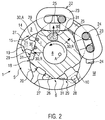
- Fig. 2 shows a schematic sectional view through the axial center plane M of another embodiment of a pocket sprocket 1 perpendicular to the axial direction A.
- a pocket sprocket 1 perpendicular to the axial direction A.
- the standing chain links 23 lie in the deep and narrow pockets 4 in the axial center plane 4.
- the chain links 23, 24 may rest on the respective base 20, 26 of the pockets 3, 4.
- the chain links 23, 24 have a thickened weld 25.
- the recesses 10 overlap in the axial direction A and a base 28 of the recesses 10 can lie within the axial projection of the projection 15.
- the recess 10 may extend so deeply between two successive similar pockets 3 in the axial direction, so that the base 28 lies in the circumferential direction U between these pockets.
- Cutouts 29 schematically show the fiber-reinforced plastic in magnification.
- the main fiber direction 30, ie the direction in which the majority of the plastic reinforcing fibers 31 are aligned, points in the interior I of the pocket sprocket, in the area between the pockets 3, 4 and the hub 8, in the radial direction R.
- Am Reason 20, 26 of the pockets 3, 4, the main fiber direction 30, however, surface-parallel preferably in the axial direction A towards the edge 14 out.
- the main fiber directions 30 are distributed symmetrically.
- the radial main fiber direction 30 in the interior I of the pocket sprocket causes a high compressive strength and thus a high load capacity of the pocket sprocket 1.
- the surface-parallel fiber flow on and immediately below the pockets 3, 4 causes a high wear resistance of the respective pocket bottom 20, 26th
- the plastic has a flexural strength which is increased in relation to the interior I, so that the chain links rest stably on the base 20 , 26 of the bags rest.
- the surface-parallel course of the main fiber direction 30 in the edge region has an increasing effect on the flexural rigidity.
- the pressure stability relative to the edge regions is increased.
- the load carried by the link chain can thus be passed without flow to the hub.
- Fig. 3 shows an embodiment of a pocket sprocket 1 for an obliquely rising link chain 22.
- the pockets 3, 4 due to the over the embodiment of the Fig. 1 and 2 Although changed chain position in detail other forms. Nevertheless, in principle the same elements as in the previous embodiment are present. As before, the pockets 3, 4 alternate in the circumferential direction U. Between each similar pockets is a projection 15, such as Fig. 3 can be seen by the pockets 4.
- the lying between the pockets 3 projections 15, in Fig. 3 for the sake of clarity with 15 ', are offset in the circumferential direction U in each case by half a pocket pitch with respect to the lying between the pockets 4 projections 15.
- Each projection 15 is associated with a recess 10.
- the clarity is in Fig. 3 only a recess 10 is shown.
- the recesses on the two end faces 7 (in Fig. 3 not shown) according to the associated projections also offset by half a pocket pitch to each other.
- the receiving grooves 18, 19 are present at the respective pockets 3, 4, wherein the receiving grooves 18, 19 in the pockets 3, 4 each have the same shape.
- the grooves 18 are recesses in the axial direction and open in the radial direction outward in an opening angle between 110 and 140 °.
- the orientation of the fibers in the interior I of the pocket sprocket 1 is the same as in the embodiment of FIG Fig. 1 and 2 ,
- the main fiber directions 30 follow the symmetry of the pocket sprocket 1 as in the previous embodiment.
- the pocket sprocket 1 may comprise at least one metal disk 33 or a pair of axially spaced metal disks 33 overmolded by the fiber reinforced plastic.
- the at least one metal disc 33 is coaxial with the hub 8. It may be provided with passages 34 so as not to affect the melt flow in the manufacture of the pocket sprocket 1.
- the metal disk 33 viewed in the circumferential direction, extends between at least one kind of pockets 3 or 4, so that it can support the link chain 22 when the plastic matrix breaks.
- the metal disk 34 may be provided with axially projecting portions 35 for anchoring them more securely in the plastic matrix.
- the metal disk 33 may be a sheet metal stamped part.
- the passages 34 may be stamped.
- the sections 35 may be formed by punched and bent tongues.
- the metal disc can also be used in a pocket sprocket for straight accumulating chains.
Landscapes
- Engineering & Computer Science (AREA)
- General Engineering & Computer Science (AREA)
- Mechanical Engineering (AREA)
- Gears, Cams (AREA)
- Injection Moulding Of Plastics Or The Like (AREA)
Applications Claiming Priority (2)
| Application Number | Priority Date | Filing Date | Title |
|---|---|---|---|
| DE102011055204A DE102011055204A1 (de) | 2011-11-10 | 2011-11-10 | Spritzgegossenes Taschenkettenrad aus faserverstärktem Kunststoff |
| PCT/EP2012/070503 WO2013068208A1 (de) | 2011-11-10 | 2012-10-16 | Spritzgegossenes taschenkettenrad aus faserverstärktem kunststoff |
Publications (2)
| Publication Number | Publication Date |
|---|---|
| EP2776741A1 EP2776741A1 (de) | 2014-09-17 |
| EP2776741B1 true EP2776741B1 (de) | 2016-04-13 |
Family
ID=47088837
Family Applications (1)
| Application Number | Title | Priority Date | Filing Date |
|---|---|---|---|
| EP12779010.3A Not-in-force EP2776741B1 (de) | 2011-11-10 | 2012-10-16 | Spritzgegossenes taschenkettenrad aus faserverstärktem kunststoff |
Country Status (5)
| Country | Link |
|---|---|
| US (1) | US9512913B2 (enExample) |
| EP (1) | EP2776741B1 (enExample) |
| JP (1) | JP5951031B2 (enExample) |
| DE (1) | DE102011055204A1 (enExample) |
| WO (1) | WO2013068208A1 (enExample) |
Families Citing this family (4)
| Publication number | Priority date | Publication date | Assignee | Title |
|---|---|---|---|---|
| KR101765147B1 (ko) * | 2017-02-09 | 2017-08-07 | 피엔에스테크놀러지(주) | 스트로우 검사장치 |
| US12325925B2 (en) | 2022-04-18 | 2025-06-10 | Sst Systems, Inc. | Finishing system |
| EP4427865A1 (de) * | 2023-03-09 | 2024-09-11 | Pewag Engineering GmbH | Verfahren und vorrichtung zum kettenschweissen |
| DE102023109905A1 (de) | 2023-04-19 | 2024-10-24 | Rud Ketten Rieger & Dietz Gmbh U. Co. Kg | Taschenkettenrad für schräg laufende Gliederketten |
Family Cites Families (44)
| Publication number | Priority date | Publication date | Assignee | Title |
|---|---|---|---|---|
| US325539A (en) * | 1885-09-01 | Sprocket-wheel | ||
| US662768A (en) * | 1900-03-12 | 1900-11-27 | Paul Louis Crowe | Sprocket-wheel for use on chain grates. |
| US2321702A (en) * | 1942-11-19 | 1943-06-15 | Samuel M Renkin | Chain wheel |
| US2535985A (en) * | 1947-04-12 | 1950-12-26 | Columbus Mckinnon Chain Corp | Hoist |
| DE1789814U (de) | 1958-10-04 | 1959-06-04 | Aumund Foerdererbau G M B H | Kettenrad fuer den antrieb von laschen- und rundgliederketten. |
| DE1880170U (de) * | 1963-06-19 | 1963-10-03 | Stamicarbon | Kettennussrad mit gliederkette. |
| FR1401923A (fr) * | 1964-07-22 | 1965-06-04 | King Ltd Geo W | Roue à empreintes pour chaînes |
| US3362239A (en) * | 1965-11-04 | 1968-01-09 | Russell F. Kaye | Oblique lay idler wheel |
| US3415135A (en) * | 1965-12-06 | 1968-12-10 | Columbus Mckinnon Corp | Oblique lay pocket wheel |
| FR1536434A (fr) * | 1967-07-06 | 1968-08-16 | Poirier Pauze & Cie Ets | Procédé de fabrication de noix d'entraînement ou de pièces analogues et produitsainsi obtenus |
| DE6810638U (de) | 1968-12-06 | 1969-05-08 | Graesslin Feinwerktech | Kettenrad |
| US4108014A (en) * | 1976-12-29 | 1978-08-22 | Columbus Mckinnon Corporation | Oblique lay sprocket wheel and chain construction |
| DE7732370U1 (de) | 1977-10-20 | 1979-11-15 | Kettenwerk Wickede-Ruhr Hermann Koch, 5757 Wickede | Kettenrolle fuer rundgliederketten mit segmenten als kettenauflage |
| DE3244361C1 (de) * | 1982-12-01 | 1983-11-03 | Berchem & Schaberg Gmbh, 4650 Gelsenkirchen | Verwendung einer Stahllegierung fuer Kettenraeder von Gewinnungsmaschinen und Foerderer in Bergbaubetrieben |
| DE3639784A1 (de) * | 1986-11-21 | 1988-06-01 | Rud Ketten Rieger & Dietz | Kettenrad mit taschen |
| JP2602872B2 (ja) * | 1988-01-20 | 1997-04-23 | 株式会社東芝 | 放射電磁界特性測定装置 |
| US5205793A (en) * | 1991-05-06 | 1993-04-27 | Campbell Hausfeld/Scott Fetzer Company | Rope or chain hauling pulley |
| DE4130073C2 (de) | 1991-09-06 | 1996-10-17 | Rud Ketten Rieger & Dietz | Taschenkettenrad als Umlenkrad |
| US5376220A (en) * | 1993-02-24 | 1994-12-27 | Martin Marietta Energy System, Inc. | Thermoplastic tape compaction device |
| DE4316753C2 (de) * | 1993-05-19 | 2002-01-24 | Thiele Gmbh & Co Kg | Mittelkettenförderer mit zweiteiligen Kratzeisen, insbesondere Doppelmittelkettenförderer |
| DE9409458U1 (de) | 1994-06-01 | 1995-09-28 | Rud-Kettenfabrik Rieger & Dietz Gmbh U. Co, 73432 Aalen | Taschenkettenrad |
| DE4420344C1 (de) * | 1994-06-01 | 1995-08-31 | Rud Ketten Rieger & Dietz | Taschenkettenrad |
| US5520585A (en) * | 1994-07-27 | 1996-05-28 | Green; Arthur G. | Plastic chain, module and sprocket cluster |
| JP3525961B2 (ja) * | 1995-06-02 | 2004-05-10 | 文化シヤッター株式会社 | 電動シャッター用動力伝達機構 |
| KR100574751B1 (ko) * | 1997-06-11 | 2006-04-28 | 라이트람, 엘.엘.씨. | 컨베이어 벨트용 물품 전송 조립체 |
| DE19731593C1 (de) | 1997-07-17 | 1998-11-19 | Rud Ketten Rieger & Dietz | Taschenkettenrad |
| JP3765208B2 (ja) * | 1999-09-08 | 2006-04-12 | 株式会社ジェイテクト | 電動式舵取装置 |
| DE10039565A1 (de) * | 2000-08-09 | 2002-03-07 | Rud Ketten Rieger & Dietz | Kette, Kettenrad und Kettentrieb für ein Hebezeug |
| DE10145603B4 (de) | 2001-09-15 | 2004-08-19 | Tracto-Technik Gmbh | Vorrichtung und Verfahren zum Kanalaufweiten oder -zerstören |
| DE10321801B4 (de) * | 2003-01-10 | 2024-08-08 | Muhr Und Bender Kg | Riemenspannvorrichtung |
| EP1712462B8 (en) * | 2004-01-13 | 2010-06-02 | Shimano Inc. | Crank for bicycle and method of producing the same |
| DE202004001679U1 (de) * | 2004-02-04 | 2005-06-16 | Joh. Winklhofer & Söhne GmbH und Co. KG | Spann- oder Führungsschiene mit Installationskanal |
| DE102004009535A1 (de) | 2004-02-21 | 2005-09-15 | Rud-Kettenfabrik Rieger & Dietz Gmbh U. Co. | Taschenkettenrad und Kettentrieb mit einem Taschenkettenrad |
| DE202005007915U1 (de) | 2005-05-13 | 2006-09-21 | Rud-Kettenfabrik Rieger & Dietz Gmbh U. Co. | Taschenkettenrad und Kettentrieb mit einem Taschenkettenrad |
| DE102006030984B4 (de) * | 2005-08-17 | 2016-08-04 | Caterpillar Global Mining Europe Gmbh | Kettenantriebs- oder Umlenkanordnung sowie dabei eingesetztes Kettenband |
| DE102006036163A1 (de) * | 2006-08-01 | 2008-02-07 | Stahl Crane Systems Gmbh | Umlenkrolle mit höherer Kettenausnutzung |
| DE102006036162A1 (de) * | 2006-08-01 | 2008-02-07 | Stahl Crane Systems Gmbh | Kettennuss mit höherer Tragkraft |
| DE102007031298A1 (de) * | 2007-07-05 | 2009-01-08 | Schaeffler Kg | Dämpfungsvorrichtung eines mechanischen Spannsystems für einen Zugmitteltrieb |
| DE102008018514A1 (de) * | 2008-04-12 | 2009-10-15 | Voss Automotive Gmbh | Verfahren zur Herstellung eines Formteils mit ringförmigem Querschnitt und Formteil nach einem solchen Verfahren |
| AU2010212914A1 (en) * | 2009-02-12 | 2011-09-01 | Kringlan Composites Ag | Method and apparatus for producing parts of fiber reinforced plastics |
| DE102011108230A1 (de) * | 2011-05-30 | 2012-12-06 | Liebherr-Werk Nenzing Gmbh | Seilrolle |
| US9440706B2 (en) * | 2013-05-07 | 2016-09-13 | Shimano Inc. | Bicycle sprocket |
| US9555855B2 (en) * | 2013-05-07 | 2017-01-31 | Shimano Inc. | Bicycle sprocket |
| US9829085B2 (en) * | 2013-05-07 | 2017-11-28 | Shimano Inc. | Bicycle sprocket |
-
2011
- 2011-11-10 DE DE102011055204A patent/DE102011055204A1/de not_active Withdrawn
-
2012
- 2012-10-16 JP JP2014540379A patent/JP5951031B2/ja not_active Expired - Fee Related
- 2012-10-16 US US14/356,523 patent/US9512913B2/en not_active Expired - Fee Related
- 2012-10-16 EP EP12779010.3A patent/EP2776741B1/de not_active Not-in-force
- 2012-10-16 WO PCT/EP2012/070503 patent/WO2013068208A1/de not_active Ceased
Also Published As
| Publication number | Publication date |
|---|---|
| JP2015505352A (ja) | 2015-02-19 |
| EP2776741A1 (de) | 2014-09-17 |
| DE102011055204A1 (de) | 2013-05-16 |
| US9512913B2 (en) | 2016-12-06 |
| US20140315674A1 (en) | 2014-10-23 |
| WO2013068208A1 (de) | 2013-05-16 |
| JP5951031B2 (ja) | 2016-07-13 |
Similar Documents
| Publication | Publication Date | Title |
|---|---|---|
| DE60305206T2 (de) | Leichtes kettenrad | |
| DE60023365T2 (de) | Geformter Kühllüfter | |
| DE69325513T2 (de) | Gummigleiskette | |
| EP1184601B1 (de) | Zahnrad | |
| EP2159441B1 (de) | Schwimmende Bremsscheibe | |
| EP2776741B1 (de) | Spritzgegossenes taschenkettenrad aus faserverstärktem kunststoff | |
| EP2776305B1 (de) | Gleiskette oder gleiskettensegment | |
| EP3789635B1 (de) | Zahnrad | |
| DD145509A5 (de) | Kreissaegeblatt | |
| EP2918430B1 (de) | Fahrwerkslenker für ein Kraftfahrzeug | |
| DE60304725T2 (de) | Treibriemen mit querelementen und stanzvorrichtung zum herstellen von querelementen | |
| EP3610173A1 (de) | Gelenkkette | |
| WO2022268678A1 (de) | Riementrieb und zahnriemen mit zahnseitigen vorsprüngen | |
| DE102004002847B4 (de) | KFZ-Zahnradanordnung für ein KFZ-Hilfsgetriebe und Verfahren zum Herstellen einer solchen KFZ-Zahnradanordnung | |
| EP1774196B1 (de) | Vorrichtung zur übertragung eines drehmoments | |
| EP0450017B1 (de) | Verfahren zur herstellung eines wälzlagerkäfigs mit angeformten federelementen und danach hergestellter wälzlagerkäfig | |
| AT391172B (de) | Zahnriemen | |
| EP3568604B1 (de) | Faltenbalg mit mindestens einer innennut | |
| EP3894720B1 (de) | Betriebsfest ausgelegte seitenlasche für eine energieführungskette | |
| WO2015070974A1 (de) | Gummibandkettensegment | |
| EP4446614A1 (de) | Zahnscheibe | |
| DE102004064237B3 (de) | KFZ-Zahnradanordnung für ein KFZ-Hilfsgetriebe sowie Flansch | |
| EP1271001A2 (de) | Geräuschgedämpftes Zahnrad | |
| DE102013209439A1 (de) | Torsionselement | |
| DE4233406B4 (de) | Kupplungsscheibe mit einer Kunststoffnabe |
Legal Events
| Date | Code | Title | Description |
|---|---|---|---|
| PUAI | Public reference made under article 153(3) epc to a published international application that has entered the european phase |
Free format text: ORIGINAL CODE: 0009012 |
|
| 17P | Request for examination filed |
Effective date: 20140428 |
|
| AK | Designated contracting states |
Kind code of ref document: A1 Designated state(s): AL AT BE BG CH CY CZ DE DK EE ES FI FR GB GR HR HU IE IS IT LI LT LU LV MC MK MT NL NO PL PT RO RS SE SI SK SM TR |
|
| DAX | Request for extension of the european patent (deleted) | ||
| GRAP | Despatch of communication of intention to grant a patent |
Free format text: ORIGINAL CODE: EPIDOSNIGR1 |
|
| INTG | Intention to grant announced |
Effective date: 20151120 |
|
| GRAS | Grant fee paid |
Free format text: ORIGINAL CODE: EPIDOSNIGR3 |
|
| GRAA | (expected) grant |
Free format text: ORIGINAL CODE: 0009210 |
|
| AK | Designated contracting states |
Kind code of ref document: B1 Designated state(s): AL AT BE BG CH CY CZ DE DK EE ES FI FR GB GR HR HU IE IS IT LI LT LU LV MC MK MT NL NO PL PT RO RS SE SI SK SM TR |
|
| REG | Reference to a national code |
Ref country code: GB Ref legal event code: FG4D Free format text: NOT ENGLISH |
|
| REG | Reference to a national code |
Ref country code: AT Ref legal event code: REF Ref document number: 790502 Country of ref document: AT Kind code of ref document: T Effective date: 20160415 Ref country code: CH Ref legal event code: EP |
|
| REG | Reference to a national code |
Ref country code: IE Ref legal event code: FG4D Free format text: LANGUAGE OF EP DOCUMENT: GERMAN |
|
| REG | Reference to a national code |
Ref country code: DE Ref legal event code: R096 Ref document number: 502012006739 Country of ref document: DE |
|
| REG | Reference to a national code |
Ref country code: CH Ref legal event code: NV Representative=s name: BOVARD AG, CH |
|
| REG | Reference to a national code |
Ref country code: LT Ref legal event code: MG4D |
|
| REG | Reference to a national code |
Ref country code: NL Ref legal event code: MP Effective date: 20160413 |
|
| REG | Reference to a national code |
Ref country code: FR Ref legal event code: PLFP Year of fee payment: 5 |
|
| PG25 | Lapsed in a contracting state [announced via postgrant information from national office to epo] |
Ref country code: NL Free format text: LAPSE BECAUSE OF FAILURE TO SUBMIT A TRANSLATION OF THE DESCRIPTION OR TO PAY THE FEE WITHIN THE PRESCRIBED TIME-LIMIT Effective date: 20160413 Ref country code: PL Free format text: LAPSE BECAUSE OF FAILURE TO SUBMIT A TRANSLATION OF THE DESCRIPTION OR TO PAY THE FEE WITHIN THE PRESCRIBED TIME-LIMIT Effective date: 20160413 Ref country code: LT Free format text: LAPSE BECAUSE OF FAILURE TO SUBMIT A TRANSLATION OF THE DESCRIPTION OR TO PAY THE FEE WITHIN THE PRESCRIBED TIME-LIMIT Effective date: 20160413 Ref country code: NO Free format text: LAPSE BECAUSE OF FAILURE TO SUBMIT A TRANSLATION OF THE DESCRIPTION OR TO PAY THE FEE WITHIN THE PRESCRIBED TIME-LIMIT Effective date: 20160713 |
|
| PG25 | Lapsed in a contracting state [announced via postgrant information from national office to epo] |
Ref country code: PT Free format text: LAPSE BECAUSE OF FAILURE TO SUBMIT A TRANSLATION OF THE DESCRIPTION OR TO PAY THE FEE WITHIN THE PRESCRIBED TIME-LIMIT Effective date: 20160816 Ref country code: HR Free format text: LAPSE BECAUSE OF FAILURE TO SUBMIT A TRANSLATION OF THE DESCRIPTION OR TO PAY THE FEE WITHIN THE PRESCRIBED TIME-LIMIT Effective date: 20160413 Ref country code: LV Free format text: LAPSE BECAUSE OF FAILURE TO SUBMIT A TRANSLATION OF THE DESCRIPTION OR TO PAY THE FEE WITHIN THE PRESCRIBED TIME-LIMIT Effective date: 20160413 Ref country code: RS Free format text: LAPSE BECAUSE OF FAILURE TO SUBMIT A TRANSLATION OF THE DESCRIPTION OR TO PAY THE FEE WITHIN THE PRESCRIBED TIME-LIMIT Effective date: 20160413 Ref country code: SE Free format text: LAPSE BECAUSE OF FAILURE TO SUBMIT A TRANSLATION OF THE DESCRIPTION OR TO PAY THE FEE WITHIN THE PRESCRIBED TIME-LIMIT Effective date: 20160413 Ref country code: ES Free format text: LAPSE BECAUSE OF FAILURE TO SUBMIT A TRANSLATION OF THE DESCRIPTION OR TO PAY THE FEE WITHIN THE PRESCRIBED TIME-LIMIT Effective date: 20160413 Ref country code: GR Free format text: LAPSE BECAUSE OF FAILURE TO SUBMIT A TRANSLATION OF THE DESCRIPTION OR TO PAY THE FEE WITHIN THE PRESCRIBED TIME-LIMIT Effective date: 20160714 |
|
| PG25 | Lapsed in a contracting state [announced via postgrant information from national office to epo] |
Ref country code: IT Free format text: LAPSE BECAUSE OF FAILURE TO SUBMIT A TRANSLATION OF THE DESCRIPTION OR TO PAY THE FEE WITHIN THE PRESCRIBED TIME-LIMIT Effective date: 20160413 |
|
| REG | Reference to a national code |
Ref country code: DE Ref legal event code: R097 Ref document number: 502012006739 Country of ref document: DE |
|
| PG25 | Lapsed in a contracting state [announced via postgrant information from national office to epo] |
Ref country code: CZ Free format text: LAPSE BECAUSE OF FAILURE TO SUBMIT A TRANSLATION OF THE DESCRIPTION OR TO PAY THE FEE WITHIN THE PRESCRIBED TIME-LIMIT Effective date: 20160413 Ref country code: SK Free format text: LAPSE BECAUSE OF FAILURE TO SUBMIT A TRANSLATION OF THE DESCRIPTION OR TO PAY THE FEE WITHIN THE PRESCRIBED TIME-LIMIT Effective date: 20160413 Ref country code: RO Free format text: LAPSE BECAUSE OF FAILURE TO SUBMIT A TRANSLATION OF THE DESCRIPTION OR TO PAY THE FEE WITHIN THE PRESCRIBED TIME-LIMIT Effective date: 20160413 Ref country code: EE Free format text: LAPSE BECAUSE OF FAILURE TO SUBMIT A TRANSLATION OF THE DESCRIPTION OR TO PAY THE FEE WITHIN THE PRESCRIBED TIME-LIMIT Effective date: 20160413 Ref country code: DK Free format text: LAPSE BECAUSE OF FAILURE TO SUBMIT A TRANSLATION OF THE DESCRIPTION OR TO PAY THE FEE WITHIN THE PRESCRIBED TIME-LIMIT Effective date: 20160413 |
|
| PLBE | No opposition filed within time limit |
Free format text: ORIGINAL CODE: 0009261 |
|
| STAA | Information on the status of an ep patent application or granted ep patent |
Free format text: STATUS: NO OPPOSITION FILED WITHIN TIME LIMIT |
|
| PG25 | Lapsed in a contracting state [announced via postgrant information from national office to epo] |
Ref country code: BE Free format text: LAPSE BECAUSE OF NON-PAYMENT OF DUE FEES Effective date: 20161031 Ref country code: SM Free format text: LAPSE BECAUSE OF FAILURE TO SUBMIT A TRANSLATION OF THE DESCRIPTION OR TO PAY THE FEE WITHIN THE PRESCRIBED TIME-LIMIT Effective date: 20160413 |
|
| 26N | No opposition filed |
Effective date: 20170116 |
|
| REG | Reference to a national code |
Ref country code: DE Ref legal event code: R119 Ref document number: 502012006739 Country of ref document: DE |
|
| PG25 | Lapsed in a contracting state [announced via postgrant information from national office to epo] |
Ref country code: SI Free format text: LAPSE BECAUSE OF FAILURE TO SUBMIT A TRANSLATION OF THE DESCRIPTION OR TO PAY THE FEE WITHIN THE PRESCRIBED TIME-LIMIT Effective date: 20160413 |
|
| GBPC | Gb: european patent ceased through non-payment of renewal fee |
Effective date: 20161016 |
|
| REG | Reference to a national code |
Ref country code: IE Ref legal event code: MM4A |
|
| PG25 | Lapsed in a contracting state [announced via postgrant information from national office to epo] |
Ref country code: DE Free format text: LAPSE BECAUSE OF NON-PAYMENT OF DUE FEES Effective date: 20170503 Ref country code: GB Free format text: LAPSE BECAUSE OF NON-PAYMENT OF DUE FEES Effective date: 20161016 |
|
| PG25 | Lapsed in a contracting state [announced via postgrant information from national office to epo] |
Ref country code: LU Free format text: LAPSE BECAUSE OF NON-PAYMENT OF DUE FEES Effective date: 20161016 |
|
| REG | Reference to a national code |
Ref country code: FR Ref legal event code: PLFP Year of fee payment: 6 |
|
| PG25 | Lapsed in a contracting state [announced via postgrant information from national office to epo] |
Ref country code: IE Free format text: LAPSE BECAUSE OF NON-PAYMENT OF DUE FEES Effective date: 20161016 |
|
| REG | Reference to a national code |
Ref country code: BE Ref legal event code: MM Effective date: 20161031 |
|
| PG25 | Lapsed in a contracting state [announced via postgrant information from national office to epo] |
Ref country code: HU Free format text: LAPSE BECAUSE OF FAILURE TO SUBMIT A TRANSLATION OF THE DESCRIPTION OR TO PAY THE FEE WITHIN THE PRESCRIBED TIME-LIMIT; INVALID AB INITIO Effective date: 20121016 |
|
| PG25 | Lapsed in a contracting state [announced via postgrant information from national office to epo] |
Ref country code: CY Free format text: LAPSE BECAUSE OF FAILURE TO SUBMIT A TRANSLATION OF THE DESCRIPTION OR TO PAY THE FEE WITHIN THE PRESCRIBED TIME-LIMIT Effective date: 20160413 Ref country code: MK Free format text: LAPSE BECAUSE OF FAILURE TO SUBMIT A TRANSLATION OF THE DESCRIPTION OR TO PAY THE FEE WITHIN THE PRESCRIBED TIME-LIMIT Effective date: 20160413 Ref country code: IS Free format text: LAPSE BECAUSE OF FAILURE TO SUBMIT A TRANSLATION OF THE DESCRIPTION OR TO PAY THE FEE WITHIN THE PRESCRIBED TIME-LIMIT Effective date: 20160413 Ref country code: MC Free format text: LAPSE BECAUSE OF FAILURE TO SUBMIT A TRANSLATION OF THE DESCRIPTION OR TO PAY THE FEE WITHIN THE PRESCRIBED TIME-LIMIT Effective date: 20160413 Ref country code: MT Free format text: LAPSE BECAUSE OF FAILURE TO SUBMIT A TRANSLATION OF THE DESCRIPTION OR TO PAY THE FEE WITHIN THE PRESCRIBED TIME-LIMIT Effective date: 20160413 |
|
| PG25 | Lapsed in a contracting state [announced via postgrant information from national office to epo] |
Ref country code: BG Free format text: LAPSE BECAUSE OF FAILURE TO SUBMIT A TRANSLATION OF THE DESCRIPTION OR TO PAY THE FEE WITHIN THE PRESCRIBED TIME-LIMIT Effective date: 20160413 |
|
| REG | Reference to a national code |
Ref country code: FR Ref legal event code: PLFP Year of fee payment: 7 |
|
| PG25 | Lapsed in a contracting state [announced via postgrant information from national office to epo] |
Ref country code: TR Free format text: LAPSE BECAUSE OF FAILURE TO SUBMIT A TRANSLATION OF THE DESCRIPTION OR TO PAY THE FEE WITHIN THE PRESCRIBED TIME-LIMIT Effective date: 20160413 Ref country code: AL Free format text: LAPSE BECAUSE OF FAILURE TO SUBMIT A TRANSLATION OF THE DESCRIPTION OR TO PAY THE FEE WITHIN THE PRESCRIBED TIME-LIMIT Effective date: 20160413 |
|
| PGFP | Annual fee paid to national office [announced via postgrant information from national office to epo] |
Ref country code: FI Payment date: 20191029 Year of fee payment: 8 |
|
| PGFP | Annual fee paid to national office [announced via postgrant information from national office to epo] |
Ref country code: FR Payment date: 20191026 Year of fee payment: 8 |
|
| PGFP | Annual fee paid to national office [announced via postgrant information from national office to epo] |
Ref country code: CH Payment date: 20191025 Year of fee payment: 8 |
|
| REG | Reference to a national code |
Ref country code: CH Ref legal event code: PL Ref country code: FI Ref legal event code: MAE |
|
| PG25 | Lapsed in a contracting state [announced via postgrant information from national office to epo] |
Ref country code: FI Free format text: LAPSE BECAUSE OF NON-PAYMENT OF DUE FEES Effective date: 20201016 Ref country code: FR Free format text: LAPSE BECAUSE OF NON-PAYMENT OF DUE FEES Effective date: 20201031 |
|
| PG25 | Lapsed in a contracting state [announced via postgrant information from national office to epo] |
Ref country code: CH Free format text: LAPSE BECAUSE OF NON-PAYMENT OF DUE FEES Effective date: 20201031 Ref country code: LI Free format text: LAPSE BECAUSE OF NON-PAYMENT OF DUE FEES Effective date: 20201031 |
|
| PGFP | Annual fee paid to national office [announced via postgrant information from national office to epo] |
Ref country code: AT Payment date: 20211027 Year of fee payment: 10 |
|
| REG | Reference to a national code |
Ref country code: AT Ref legal event code: MM01 Ref document number: 790502 Country of ref document: AT Kind code of ref document: T Effective date: 20221016 |
|
| PG25 | Lapsed in a contracting state [announced via postgrant information from national office to epo] |
Ref country code: AT Free format text: LAPSE BECAUSE OF NON-PAYMENT OF DUE FEES Effective date: 20221016 |