EP2776606B1 - Method for the electrochemical generation of oxygen and hydrogen - Google Patents
Method for the electrochemical generation of oxygen and hydrogen Download PDFInfo
- Publication number
- EP2776606B1 EP2776606B1 EP12790944.8A EP12790944A EP2776606B1 EP 2776606 B1 EP2776606 B1 EP 2776606B1 EP 12790944 A EP12790944 A EP 12790944A EP 2776606 B1 EP2776606 B1 EP 2776606B1
- Authority
- EP
- European Patent Office
- Prior art keywords
- mediator
- hydrogen
- oxygen
- oxidised
- electrode
- Prior art date
- Legal status (The legal status is an assumption and is not a legal conclusion. Google has not performed a legal analysis and makes no representation as to the accuracy of the status listed.)
- Active
Links
Images


Classifications
-
- C—CHEMISTRY; METALLURGY
- C25—ELECTROLYTIC OR ELECTROPHORETIC PROCESSES; APPARATUS THEREFOR
- C25B—ELECTROLYTIC OR ELECTROPHORETIC PROCESSES FOR THE PRODUCTION OF COMPOUNDS OR NON-METALS; APPARATUS THEREFOR
- C25B1/00—Electrolytic production of inorganic compounds or non-metals
- C25B1/01—Products
- C25B1/02—Hydrogen or oxygen
- C25B1/04—Hydrogen or oxygen by electrolysis of water
-
- C—CHEMISTRY; METALLURGY
- C25—ELECTROLYTIC OR ELECTROPHORETIC PROCESSES; APPARATUS THEREFOR
- C25B—ELECTROLYTIC OR ELECTROPHORETIC PROCESSES FOR THE PRODUCTION OF COMPOUNDS OR NON-METALS; APPARATUS THEREFOR
- C25B1/00—Electrolytic production of inorganic compounds or non-metals
- C25B1/50—Processes
- C25B1/55—Photoelectrolysis
-
- C—CHEMISTRY; METALLURGY
- C25—ELECTROLYTIC OR ELECTROPHORETIC PROCESSES; APPARATUS THEREFOR
- C25B—ELECTROLYTIC OR ELECTROPHORETIC PROCESSES FOR THE PRODUCTION OF COMPOUNDS OR NON-METALS; APPARATUS THEREFOR
- C25B15/00—Operating or servicing cells
- C25B15/08—Supplying or removing reactants or electrolytes; Regeneration of electrolytes
-
- C—CHEMISTRY; METALLURGY
- C25—ELECTROLYTIC OR ELECTROPHORETIC PROCESSES; APPARATUS THEREFOR
- C25B—ELECTROLYTIC OR ELECTROPHORETIC PROCESSES FOR THE PRODUCTION OF COMPOUNDS OR NON-METALS; APPARATUS THEREFOR
- C25B5/00—Electrogenerative processes, i.e. processes for producing compounds in which electricity is generated simultaneously
-
- C—CHEMISTRY; METALLURGY
- C25—ELECTROLYTIC OR ELECTROPHORETIC PROCESSES; APPARATUS THEREFOR
- C25B—ELECTROLYTIC OR ELECTROPHORETIC PROCESSES FOR THE PRODUCTION OF COMPOUNDS OR NON-METALS; APPARATUS THEREFOR
- C25B9/00—Cells or assemblies of cells; Constructional parts of cells; Assemblies of constructional parts, e.g. electrode-diaphragm assemblies; Process-related cell features
- C25B9/70—Assemblies comprising two or more cells
- C25B9/73—Assemblies comprising two or more cells of the filter-press type
-
- Y—GENERAL TAGGING OF NEW TECHNOLOGICAL DEVELOPMENTS; GENERAL TAGGING OF CROSS-SECTIONAL TECHNOLOGIES SPANNING OVER SEVERAL SECTIONS OF THE IPC; TECHNICAL SUBJECTS COVERED BY FORMER USPC CROSS-REFERENCE ART COLLECTIONS [XRACs] AND DIGESTS
- Y02—TECHNOLOGIES OR APPLICATIONS FOR MITIGATION OR ADAPTATION AGAINST CLIMATE CHANGE
- Y02E—REDUCTION OF GREENHOUSE GAS [GHG] EMISSIONS, RELATED TO ENERGY GENERATION, TRANSMISSION OR DISTRIBUTION
- Y02E60/00—Enabling technologies; Technologies with a potential or indirect contribution to GHG emissions mitigation
- Y02E60/30—Hydrogen technology
- Y02E60/36—Hydrogen production from non-carbon containing sources, e.g. by water electrolysis
-
- Y—GENERAL TAGGING OF NEW TECHNOLOGICAL DEVELOPMENTS; GENERAL TAGGING OF CROSS-SECTIONAL TECHNOLOGIES SPANNING OVER SEVERAL SECTIONS OF THE IPC; TECHNICAL SUBJECTS COVERED BY FORMER USPC CROSS-REFERENCE ART COLLECTIONS [XRACs] AND DIGESTS
- Y02—TECHNOLOGIES OR APPLICATIONS FOR MITIGATION OR ADAPTATION AGAINST CLIMATE CHANGE
- Y02P—CLIMATE CHANGE MITIGATION TECHNOLOGIES IN THE PRODUCTION OR PROCESSING OF GOODS
- Y02P20/00—Technologies relating to chemical industry
- Y02P20/10—Process efficiency
- Y02P20/133—Renewable energy sources, e.g. sunlight
Definitions
- the present invention relates to methods for the preparation of hydrogen and oxygen using electrochemical means, and optionally using light as a source of power.
- the invention also relates to the use of a redox active chemical mediator in such methods.
- Oxygen-evolving reaction (OER): 2 H 2 O ⁇ O 2 + 4 H + + 4 e ⁇ E oxidation ⁇ 1.23 V
- Equations 1 and 2 give the half-reactions for water-splitting at room temperature at pH 0, showing that the theoretical minimum voltage which must be supplied to drive the OER and the HER simultaneously is 1.23 V. In practice, however, additional energy (hereafter termed “overpotential”) must be supplied to surmount various systemic and kinetic barriers, which means that voltages well in excess of 1.6 V are typically needed in order to provide simultaneous OER and HER.
- overpotential additional energy
- a particular focus of the research into hydrogen and oxygen production is the utilisation of light as an energy source for the electrochemical reaction. In some circumstances this may simply be the use of photovoltaic cells to provide the bias in a hydrogen- and oxygen-producing electrochemical cell.
- photoelectrochemical cells for hydrogen and oxygen production.
- a photoresponsive material is present within the cell itself, and its photochemical response drives the electrochemistry within the cell.
- the photo-responsive material may be referred to as a photocatalyst, for example.
- Materials that have been found suitable for use in the generation of oxygen from water include WO 3 (see Erbs et al. ), which may be combined with other materials for improved photocatalytic activity.
- a redox mediator is employed to facilitate the electrochemical generation of hydrogen and oxygen, allowing the large voltage gap between OER onset and HER onset to be traversed in two smaller steps.
- the use of a mediator removes the requirement that a single photocatalyst must simultaneously effect water oxidation and proton reduction, and instead couples separate, optimized photocatalyst ensembles for OER and HER together.
- Fe 3+ is used as the mediator, which is reduced to Fe 2+ with concomitant production of oxygen.
- the authors focus on improving the generation of oxygen only.
- the reduced iron species it is noted, may be regenerated as Fe 3+ in a separate electrochemical step, using a photocatalyst and a sacrificial electron donor, such as an organic compound.
- the mediator is not linked to the production of hydrogen.
- US 2004/0256247 also describes the possibility of generating hydrogen and oxygen.
- a mediator is oxidised at an electrode, with generation of oxygen also observed at the same electrode, namely the anolyte side.
- hydrogen is generated at the catholyte side only.
- the evolution of the gases is not linked to the mediator, and instead arises from other reactions that occur in the electrochemical cell. Again, the gases are evolved simultaneously, in this case as byproducts during the electrochemical destruction of organic waste.
- a system and a method that are suitable for use with a sustainably derived energy source are particularly desirable.
- a system that is adaptable for use in a standard electrochemical cell and a photoelectrochemical cell would be particularly advantageous.
- the present inventors have identified a particular class of mediators that have useful reduction and oxidation properties. These mediators may be reliably and reproducibly exploited in a method for generating hydrogen and oxygen using electrochemical, including photoelectrochemical, means.
- the present invention provides the use of a mediator, which is capable of reversibly accepting electrons (e - ) and/or protons (H + ), in the generation of hydrogen and/or oxygen from water.
- the mediator has a reversible redox wave lying between the onset of the oxygen evolution reaction (OER) and the hydrogen evolution reaction (HER).
- the reduction peak may be a one, two, or multi-electroredox wave.
- the mediator is capable of accepting and donating electrons, or accepting and donating electrons and protons.
- the mediator is a polyoxometallate, for example [MO 12 PO 40 ] 3- and [MO 12 PO 40 ] 5- , and the acidic forms thereof, for example H 3 Mo 12 PO 40 and H 5 Mo 12 PO 40 .
- the mediator is a quinone compound, together with the dihydro form thereof.
- the mediator described herein may be used at high concentrations within an electrochemical cell. At such concentrations, the mediator may be used advantageously to decouple the oxygen and hydrogen-evolving half reactions of water electrolysis.
- the mediator described herein is oxidatively and thermally stable.
- the mediator allows hydrogen and oxygen to be generated as a two-step process, via the oxidation and reduction of the mediator. Each of these steps may be performed using a relatively low voltage. This may be contrasted with a method where oxygen and hydrogen are generated in one step without a mediator. Here the voltage required (both on a theoretical and practical level) is significantly higher.
- methods utilising a mediator are particularly suitable for situations where the power supply is limited, for example in developing nations where electrical supply is uncertain.
- the use of lower voltages is associated with reduced degradation of the components of an electrochemical cell, for example the electrodes, the membrane and other components.
- Decoupling oxygen and hydrogen production steps also has the advantage that, for a given voltage, the rates of production are increased. Production rates in systems where the oxygen and the hydrogen production are tightly coupled are generally relatively low.
- the systems developed, which incorporate the mediator described herein can provide extremely high Faradaic efficiencies.
- the methods of the present invention have at least 90% Faradaic efficiency, and may have substantially 100% Faradaic efficiency.
- the mediator is suitable for use in methods having a high current flow.
- the use of the mediator is not associated with mass transfer limitations in the electrochemical reactions described herein.
- the rate of electron and/or proton transfer is relatively fast, and useful quantities of hydrogen and oxygen may be produced in a practical time frame.
- the invention provides a method for the generation of hydrogen and oxygen, the method comprising the steps of:
- the hydrogen and oxygen generating steps may be referred to as the electrolysis of water.
- the mediator such as a polyoxometallate, acts as a mediator by accepting, storing and donating electrons and protons between the oxygen and hydrogen generation steps.
- the generation of hydrogen and oxygen may be performed as a two-step photoexcitation (Z-scheme).
- the oxygen generation step is performed non-simultaneously to the hydrogen generation step.
- two smaller energy inputs are used to split water to give hydrogen and oxygen at different times, as opposed to a single energy input which produces hydrogen and oxygen simultaneously.
- the method described herein may be performed at modest voltages, for example at voltages of about 1.0 V.
- the methods described herein are safe, require low power, and may be combined with photoelectrochemical methods, for example utilising sunlight as a power source to power the electrochemical generation of hydrogen and/or oxygen.
- step (ii) comprises oxidising the mediator at a working electrode to yield an oxidised mediator, and reducing protons at a counter electrode to yield hydrogen.
- mediator is a H + donor and/or acceptor.
- the mediator and the oxidised mediator are prevented from contacting the counter electrode.
- the mediator has a reversible redox wave lying in the range +0.3 to +0.9 V vs NHE.
- the mediator is a polyoxometallate.
- the polyoxometallate and/or the oxidised polyoxometallate comprises 2, 3, 6, 7, 12, 18, 24, 30 or 132 metal atoms.
- the metal atoms in the polyoxometallate and/or the oxidised polyoxometallate are selected from the group consisting of W, Mo, V and Nb, and combinations thereof. More preferably, the polyoxometallate is of formula [M 12 O 40 X] n- where M is a metal, such as Mo, W or V, or mixtures thereof, X is P or S, and n is 3, 4, 5 or 6 as appropriate.
- the oxidised polyoxometallate is H 3 Mo 12 PO 40 and the polyoxometallate is H 5 Mo 12 PO 40 .
- the oxidised mediator is a quinone compound and the mediator is a dihydrobenzene compound.
- the oxidised mediator is a 1,4-quinone compound and the mediator is a 1,4-dihydrobenzene compound.
- step (i) comprises reducing an oxidised mediator at a carbon working electrode to yield a mediator.
- step (i) comprises oxidising water at a Pt counter electrode to yield oxygen.
- the present invention provides methods for the electrochemical generation of hydrogen and oxygen using a mediator as an electron donor and acceptor in an electrochemical cell.
- the mediator may also be a proton donor and acceptor, and the mediator may act as a buffer for the electrolyte in an electrochemical cell.
- the mediator has a reversible redox wave at a potential between the onset of the oxygen evolution reaction (OER) and the hydrogen evolution reaction (HER).
- the present inventors have found that a polyoxometallate may be used as a mediator in an electrochemical process for the generation of hydrogen and oxygen.
- the mediator is capable of reversibly accepting and donating electrons in these electrochemical processes, and optionally also accepting and donating protons.
- the present inventors have found that compounds having a quinone group may be similarly used for this purpose.
- the mediator may accept protons and electrons.
- the resultant reduced and protonated mediator may then donate protons and electrons in a subsequent hydrogen generating step.
- a reduced and protonated mediator may be used initially to generate hydrogen, and the resultant oxidised mediator may then accept protons and electrons in a subsequent oxygen generating step.
- polyoxometallates as catalysts in water splitting reactions has been previously described (see review by Long et al.).
- the catalyst is used to lower the kinetic barrier to splitting water into hydrogen and oxygen. This may be contrasted with the methods described herein which utilize a polyoxometallate as an electron and hydrogen donor and acceptor in an electrochemical water splitting system.
- Mediators that can reversibly store the protons and electrons produced during electrolytic water oxidation are particularly attractive for their ability to break the voltage input necessary to split water into two.
- Mediators for use in the present invention are those that are preferably highly water soluble, can effectively buffer the pH during water splitting, have fully reversible and cycle-able redox waves in between OER and HER, are stable in both their oxidised and reduced forms, and do not cause degradation of other components within the cell (e.g. electrodes and membranes).
- the OER is decoupled from the HER, allowing O 2 and H 2 to be produced entirely separately in both space and time.
- a reference to a mediator is a reference to a reduced mediator. Such a mediator may therefore be oxidised (to give an oxidised mediator). In one embodiment, a reference to a mediator is a reference to an oxidised mediator. Such a mediator may therefore be reduced (to give a reduced mediator).
- the context will dictate whether reference is intended to a reduced or oxidised form of a mediator, as will be clear to a person of skill in the art.
- the mediator acts as a couple and is interconverted between oxidised and reduced forms, and this may occur within the electrochemical cell.
- the mediators are oxidatively stable, and preferably thermally stable also.
- the present invention makes use of a mediator that has (at least) two different oxidation states, which oxidation states may be accessed by oxidation or reduction from one state to the other.
- a mediator is thermally and oxidatively stable in both the oxidised form and the reduced form.
- the mediator has minimal cross reactivity with other components within an electronically cell (e.g. the electrodes and other components of the electrolyte).
- the mediator may also be stable to light, particularly visible light. This characteristic is useful, as recent developments in the production of oxygen and hydrogen, utilise photoactive components to provide the electromotive power for the methods.
- a mediator that is stable to illumination from visible light sources, such as sun light, is particularly desirable.
- the mediator for use in the present invention is a polyoxometallate.
- the polyoxometallate is an oxo-anion of a transition metal cluster.
- the polyoxometallate is an acidic polyoxometallate, and references to polyoxometallate may be construed accordingly.
- Polyoxometallates for use as mediators, and the acid forms thereof, are thermally and oxidatively stable.
- the mediator for use in the present invention is a compound having a quinone group (a quinone compound).
- the reduced form of the quinone compound is a compound having a 1,4-dihydrobenzene or a 1,2-dihydrobenzene group.
- the quinone compound may include functional groups, such as hydroxyl, amino, carboxy, sulphate, and poly(alkyleneglycol) groups, which may solubilise the compound in an aqueous electrolyte.
- polyoxometallates in a reduced or oxidised form, may be stored under ambient laboratory conditions (with respect to heat, light, pressure and humidity amongst others) for at least 25 days without appreciable decomposition.
- the integrity of a polyoxometallate may be gauged over time using standard analytical techniques, such as UV-Vis and NMR spectroscopies (for example 31 P NMR, where a P atom is present in the polyoxometallate cluster) and the like. Similar techniques may be employed to test the integrity of other mediators.
- the integrity of the mediator may be tested by employing the mediator in a number of repeat cycles of oxygen and hydrogen generation steps according to the present invention. Over number of cycles, for example 4 or more, the mediator may be present without appreciable degradation. For example, 85 % or more of the mediator, such as 90% or more, may be present after these cycles.
- At least a one electron reduction of the oxidised form of the mediator yields the reduced form.
- at least a two electron reduction of the oxidised form yields the reduced form.
- Such a mediator is beneficial as it has a higher electron accepting and donating density. Thus one cluster molecule may "hold" two or more electrons.
- the reduction or oxidation of the mediator may be associated with the gain or loss of H + from or to the mediator.
- the mediator is a H + donor and/or acceptor.
- the reduction or oxidation is associated with the gain or loss of two or more H + from or to the mediator.
- a mediator such as a polyoxometallate cluster or a quinone compound may "hold" two or more protons.
- a mediator that is capable of donating and accepting H + may act as a buffering agent in the electrolyte during the electrochemical reaction.
- the mediator is a proton and electron donor and acceptor.
- the mediator may be referred to as a proton electron buffer (PEB).
- the ability of a mediator to accept or donate protons provides a useful benefit in the systems and methods of the invention.
- the mediator has the ability to act as a pH buffer to the electrolyte by accepting protons that are generated in an oxygen production method. Conversely, as protons are consumed in a hydrogen generation method, the mediator is capable of donating protons to the system.
- some of the mediators described herein can function as a donor, acceptor and store for both electrons and protons.
- the mediator may serve as a donor, acceptor and store for electrons.
- the source of protons for the reduction reaction that yields hydrogen may be provided by a source other than the mediator. Suitable electrolyte or compositions may be provided for this purpose.
- a buffer is provided to accept and donate protons as appropriate.
- the reduced and oxidised forms of the mediator are soluble in water, and are soluble in acidified water. Thus, oxidation or reduction of the mediator does not produce an insoluble material within an electrochemical cell or a composition.
- the mediator may be an anion.
- the charge of the oxidised state of the mediator is -1 or less, for example -2, -3, -4. In one embodiment, the oxidised state has a charge of -3. In one embodiment, the charge of the reduced state of the mediator is 1 or more less than the charge of the oxidised stated of the mediator, for example, 2 more, or 3 more. Thus, where the oxidised state has a charge of -3, the reduced state may have a charge of -5. In one embodiment, the reduced state has a charge of -5.
- the mediator has a reversible redox wave, such as a 2 electron wave, at potentials between the onset of the oxygen evolution reaction (OER) and the hydrogen evolution reaction (HER).
- the mediator has a reversible redox wave lying in the range +0.3 to +0.9 V vs NHE.
- the reduction peak may a one, two, or multi-electroredox wave.
- the redox wave lies in the range +0.4 to +0.8 V vs NHE, or in the range +0.5 to +0.7 V vs NHE.
- the reversible redox wave may be determined experimentally using, for example, cyclic voltammetry experiments, as known to a person of skill in the art.
- the potentials mentioned here may refer to the potentials measured with the mediator in an electrolyte having a pH in the range 0 to 3, such as 1 to 2.
- the location of the mediator reduction peak or peaks may be determined using cyclic voltammetry, as will be familiar on of skill in the art.
- the potentials may be expressed in relation to the NHE.
- the values for the location of a mediator reduction wave may be determined for an acidic solution of the mediator, for example at a pH of about 0.3.
- the mediator exists in two oxidation states only with the range of potentials between the onset of the oxygen evolution reaction (OER) and the hydrogen evolution reaction (HER).
- the oxidation of a mediator at a potential between the onset of the oxygen evolution reaction (OER) and the hydrogen evolution reaction (HER) leads to a single oxidised product.
- the oxidised mediator is preferably not further oxidised.
- the reduction of a mediator at a potential between the onset of the oxygen evolution reaction (OER) and the hydrogen evolution reaction (HER) leads to a single reduced product.
- the reduced mediator is preferably not further reduced.
- the mediator is used in an electrolyte having a pH that is at most 6, at most 5, at most 4, at most 3, or at most 2. In one embodiment, the mediator is used in an electrolyte having a pH that is at least 0.1, at least 0.2 or at least 0.3. In one embodiment, the mediator is used in an electrolyte having a pH that is in a range having upper and lower values selected from the values above.
- the mediator is a buffering agent.
- the mediator in use, is suitable for accepting and donating protons.
- the mediator may substantially maintain the pH of the electrolyte solution during an electrochemical reaction.
- the mediators described herein can function as a donor, acceptor and store for both electrons and protons. The present inventors have established that the hydrogen and/or oxygen evolution reactions are optionally performed under conditions where the electrolyte is buffered, for example by the mediator itself.
- the mediator may be coloured i.e. the mediator may absorb light in the visible spectrum.
- the reduced and oxidised forms of the mediator are different colours.
- Such a change is a useful feature of certain mediators, such as polyoxometallates.
- the colour of the electrolyte may change.
- the changes in electrolyte colour may be a useful indicator of reaction progress, and mediator conversion with the electrolyte.
- the mediator is retained by a membrane to a working electrode part of the electrolyte space. If there is deterioration in the integrity of the membrane, such that the mediator is able to move into the counter electrode region of the electrolyte space, this may be readily detected by the operator as a change in, or the appearance of, colour in the electrolyte within the counter electrode region.
- the mediator has at least 10 atoms, at least 15 atoms or at least 20 atoms. In one embodiment, the mediator has at least 3 oxygen atoms, at least 4 oxygen atoms, or at least five oxygen atoms. In one embodiment, the mediator has a molecular weight of at least 100, at least 150, at least 200, or at least 500.
- the mediator does not contain an Fe atom. In one embodiment, the mediator does not contain an I atom.
- the mediator is an anion that may be protonated to give a neutral product.
- That neutral product may be a liquid or a solid at standard pressure and temperature (STP; 15°C, 101.325 kPa).
- the mediator may be a polyoxometallate.
- the polyoxometallate comprises at least 2, 3, 6, 7, 12, 18, 24, 30 or 132 metal atoms. In one embodiment, the polyoxometallate comprises 2, 3, 6, 7, 12, 18, 24, 30 or 132 metal atoms. In one embodiment, the polyoxometallate comprises 6, 7, 12, 18, 30 or 132 metal atoms.
- the number of oxygen atoms is determined by the number of metal atoms present in the polyoxometallate, and the particular structure adopted by the cluster.
- the polyoxometallate has 12 metal atoms. In this embodiment, the cluster may comprise 40 oxygen atoms. In one embodiment, the polyoxometallate has 18 metal atoms. In this embodiment, the cluster may comprise 54 oxygen atoms.
- the polyoxometallate may have a major metal atom component and one or more further heteroatom components selected from P, Si, S, Ge, W, V, Mo, Mn, Se, Te, As, Sb, Sn, and Ti.
- the polyoxometallate may have a major metal atom component and one or more further heteroatom components selected from W, V, Mo, Nb, Ti, V, Cr, Mn, Fe, Co, Ni, Cu, Zn, Sn, Pb, Al, and Hg.
- the metal atoms in the polyoxometallate are selected from the group consisting of W, Mo, V and Nb, and combinations thereof. In one embodiment the metal atoms in the polyoxometallate are selected from the group consisting of Mo and V, and combinations thereof. In one embodiment the metal atoms in the polyoxometallate are Mo atoms.
- the polyoxometallate may further comprise Ti, V, Cr, Mn, Fe, Co, Ni, Cu, and/or Zn. In addition to any of the W, Mo, V and/or Nb atoms present, the polyoxometallate may further comprise Sn, Pb, Al, and/or Hg.
- Polyoxometallates of the type described above are particularly favoured in view of the fact that they consist of earth-abundant elements.
- the polyoxometallate is of formula [M 12 O 40 X] n- where M is a metal, such as Mo, W or V, or mixtures thereof, X is P or S, and n is 3, 4, 5 or 6 as appropriate.
- the polyoxometallate is of formula H m M 12 O 40 X where m is 3, 4, 5 or 6 as appropriate, M is a metal, such as Mo, W or V, or mixtures thereof, and X is P or Si.
- the metal atoms in the polyoxometallate may be the same or different. Typically, the metal atoms are the same.
- the mediator is [Mo 12 PO 40 ] 3- or [Mo 12 PO 40 ] 5- , and the acidic forms thereof, for example H 3 Mo 12 PO 40 or H 5 Mo 12 PO 40 .
- [Mo 12 PO 40 ] 3- and [Mo 12 PO 40 ] 5- (and the acid forms thereof) may be used as a redox couple.
- the former may be readily converted to the latter and vice versa.
- the former may be referred to as a reduced polyoxometallate and the latter as an oxidised polyoxometallate, as context dictates.
- H 3 Mo 12 PO 40 is (H 3 O + )[H 2 Mo 12 PO 40 ] - at pH 0.3.
- Phosphomolybdic acid is well-suited to the role of a mediator for water splitting for several reasons: it is highly soluble in water at room temperature (allowing high concentrations to be accessed), it is commercially available in a form where the only counter-cation is H + , it contains no easily oxidised moieties which might decompose during electrolysis, it has several reversible 2-electron waves at potentials between the onset of the oxygen and hydrogen evolutionary reaction, it accepts charge-balancing protons when it is reduced (hence it should buffer the solution pH during water splitting), it is known to be compositionally stable within the pH range studied (see Tsigdinos et al.), and the 2-electron reduced form, (H 3 O + )[H 4 Mo 12 PO 40 ] - , reacts only slowly with oxygen in the air at room temperature i.e. both the oxidised and first reduced forms should be stable under ambient conditions.
- the mediator is a quinone compound.
- the quinone compound comprises a benzoquinone group, which may be a 1,4-benzoquinone group or a 1,2-benzoquinone group. A 1,4-benzoquinone group is preferred.
- the quinone compound may be anionic, for example in both its oxidised and reduced forms.
- the quinone compound may include anionic functionality, for example sulphate or carboxylate functionality.
- a reference to a quinone compound includes a reference to a compound having a 1,4-dihydrobenzene or a 1,2-dihydrobenzene group, as appropriate.
- the quinone compound may include functional groups, such as hydroxyl, amino, carboxy, sulphate, and poly(alkyleneglycol) groups, which may solubilise the compound in an aqueous electrolyte.
- functional groups such as hydroxyl, amino, carboxy, sulphate, and poly(alkyleneglycol) groups, which may solubilise the compound in an aqueous electrolyte.
- mediators such as polyoxometallate and quinone compounds
- the present inventors have determined that mediators, such as polyoxometallate and quinone compounds, for use in the present invention do not cause degradation of the membrane.
- the inventors have established that the membrane remains intact after at least five weeks' exposure to a polyoxometallate in an aqueous electrolyte solution.
- the oxidation and reduction of polyoxometallates may be accompanied by a colour change.
- the change in colour is associated with the appearance/disappearance of absorption bands associated with for example, intervalance charge transfer between metals of different oxidation sates within a cluster.
- Polyoxometallates are available commercially or may be prepared as required using standard techniques, such as those described by G. A. Tsigdinos, Ind. Eng. Chem., Prod. Res. Develop. 13, 267 (1974 ). The preparation, identification and use of other polyoxometallate structures are usefully reviewed in Long et al.
- Electrodes for use in systems for the generation of hydrogen and/or oxygen are well described in the art (see, for example, Damjanovic et al. as an early example).
- the electrodes for use in the present invention include those comprising or consisting of platinum, platinum oxide, palladium, iridium, iridium oxide, indium-tin oxide and/or carbon and tungsten trioxide.
- Electrodes are also suitable for use, although preferably such should be resistant to strong acid.
- the choice of electrode is dependent on the nature of the hydrogen or oxygen generation method.
- methods for the photoelectrochemical generation of hydrogen and oxygen may call for the use of a semi-conductor type electrode, or an electrode having a coating of a photocatalyst.
- the electrodes of the invention do not contain Fe.
- the use of iron-containing electrodes, such as stainless steel electrodes, has been associated with the loss of membrane integrity in (see Pozio et al. ).
- the methods described herein may also include the use of acidified electrolyte, for example at a pH of between 0 and 2.
- the electrodes selected for use should therefore be substantially resistant to acid degradation.
- a working electrode is an electrode at which a mediator is oxidised or reduced.
- a counter electrode is an electrode at which hydrogen or oxygen may be generated.
- the working electrode may be a cathode in those methods where the mediator is reduced.
- the working electrode may be an anode in those methods where the mediator is oxidised.
- the working electrode is a platinum or platinum-containing electrode.
- the working electrode may be a carbon electrode.
- the counter electrode is a platinum or platinum-containing electrode.
- the power source for the electrochemical reaction is provided by an external source.
- the electrode material may be selected for its suitability in the oxygen evolving reaction or the hydrogen evolving reaction.
- platinum is particularly suitable for use at a cathode for the hydrogen evolving reaction.
- Iridium or iridium oxide is particularly suitable for use at an anode for the oxygen evolving reaction.
- the electrode for the oxygen and hydrogen evolving steps may be the same.
- the electrode may be platinum in these circumstances.
- the electrochemical cell used for the generation of these products may be the same.
- the counter electrode for the generation of oxygen and hydrogen is the same electrode.
- a reverse in the applied bias changes the counter electrode from a cathode to an anode (or vice versa ) as appropriate. It is an advantage of the present system that the same electrochemical cell may be used to generate hydrogen and oxygen at separate times, and without the need for complicated alterations to the cell set up.
- an electrode that does not contain a metal such as platinum is advantageous in that it minimises apparatus costs.
- electrochemical benefits associated with the use of platinum and other such electrodes may provide an overall more efficient system.
- the electrode may be selected with a view to the wider benefits that result from its use and not merely the costs of preparing the electrode. Such considerations will be apparent to one of skill in the art.
- the working or counter electrode may be in the form of a wire, sheet (or foil), or mesh.
- the counter electrode may be a photovoltaic electrode.
- the electrode is or comprises material that is photoreactive. This material may be referred to as a photocatalyst. Illumination of the electrode with light of an appropriate wavelength produces free charge carriers, electrons and holes, in the photoreactive material. As described herein, the electrodes absorb visible (400 to 750 nm) or ultraviolet (10 to 400 nm) light. Thus, the electrodes may be used together with incident sun light to generate herein electrochemical changes.
- photoreactive material may be based on the role of the counter electrode in the electrochemical cell.
- a counter electrode that acts as an oxygen evolution photocatalyst may be selected on the basis of the energy levels of the conduction and valence bands. These bands may be located advantageously relative to the water oxidation potential.
- a counter electrode that acts as a hydrogen evolution photocatalyst may be selected on the basis of the energy levels of the conduction and valence bands. These bands may be located advantageously relative to the proton reduction potential.
- a WO 3 photocatalyst may be used for oxygen evolution and suitably modified TiO 2 may be used for hydrogen evolution (as reviewed by Grätzel).
- the working electrode may comprise WO 3 , optionally together with other components.
- the other components may be metals or metal oxides or metal nitrides (amongst others), and are added to increase the overall conversion efficiency of the photocatalyst.
- a photocatalyst may be present as an outer layer of an electrode.
- the photocatalyst may be provided on an electrically conductive transparent substrate. Transparency may refer to visible and/or UV light transparency.
- the substrate may be an indium-tin oxide (ITO) substrate.
- ITO indium-tin oxide
- a reference electrode may be included in the electrode cell as described herein.
- the reference electrode may be a standard silver / silver chloride electrode.
- the reference electrode may be a pseudo reference electrode, which is operable as a reference electrode in the presence of a suitable buffer comprising appropriate ions.
- the working electrode and the counter electrode, along with the reference electrode define an electrolyte space.
- the electrodes are in electrical contact with an electrolyte in said electrolyte space.
- the electrolyte is as described herein.
- an electrochemical cell comprising a working electrode, a counter electrode, optionally a reference electrode and an electrolyte.
- the electrolyte comprises a mediator, as described herein.
- the counter electrode and the working electrode are suitable for electrical connection or are electrically connected.
- the working and counter electrodes define an electrochemical space in which an electrolyte is provided.
- the electrochemical space may be divided by a semi-permeable membrane to provide a working electrode electrolyte space and a counter electrode electrolyte space.
- the mediator is provided in the working electrode electrolyte space.
- No mediator is provided in the counter electrode space.
- the semi-permeable membrane prevents movement of the mediator (in either the oxidised or reduced form) from moving from the working electrode electrolyte space to the counter electrode electrolyte space. The mediator is thereby prevented from contacting the counter electrode surface.
- a set up whereby the mediator is separated from the counter electrode side of the cell is advantageous in that the mediator cannot interfere with the chemistries that are occurring at the counter electrode.
- the mediator is kept separate from the side of the electrolyte space where the photochemistry occurs.
- the mediator may absorb light at wavelengths that overlap with the wavelengths at which the photocatalyst absorbs light. Thus, the mediator is prevented from interfering with the photochemistry.
- the wavelengths at which the mediator absorbs light may be sufficiently different from the wavelengths at which the photocatalyst absorbs light.
- the present inventors prefer to prevent the mediator from contacting the counter electrode, in order to limit cross-reactions in the system.
- the working and counter electrodes are electrically connected or connectable.
- the electrochemical cell may further comprise a voltage supply (or power supply).
- the voltage supply is preferably adapted to supply a constant bias between the working electrode and the counter electrode or the reference electrode, where present.
- the voltage supply is adapted to supply a constant bias of up to 2.0 V.
- the voltage supply may be adapted to supply a constant bias of around 1.0 V.
- the voltage supply is reversible as required.
- the electrochemical cell may derive its power from an external light source, and in particular sunlight.
- the electrodes may be in electrical connection with, for example, a photovoltaic device.
- the counter electrode may be provided with a light activateable material suitable for use in an electrochemical cell. Such electrodes are as described above.
- the electrochemical cell may further comprise a detector for monitoring current.
- the electrochemical cell may further comprise a controller for controlling the voltage supply and timing of that supply.
- the present invention relates to the generation of oxygen and hydrogen from water using a mediator.
- the electrolyte is an aqueous electrolyte.
- the electrolyte comprises the mediator.
- the mediator may be present at a concentration of at most 1.0, at most 1.5, or at most 2.0 M.
- the mediator may be present at a concentration of at least 0.1, at least 0.2 or at least 0.3, or at least 0.5 M.
- the mediator may be present at a concentration in a range selected from the upper and lower values given above, for example 0.5 to 2.0 M.
- the mediator may be present at a concentration of about 0.5 M.
- the concentrion may refer to the concentration of the mediator in the working electrode space of the electrolyte space.
- water electrolysis may be performed at any pH: under very basic or acidic conditions, or at neutral pH.
- PME proton exchange membrane electrolyser
- the advantages of a PEME over a high pH alkaline electrolyser are increased current densities ( ⁇ 2 Acm -2 for a PEME vs.
- PEMEs tend to be more efficient (and hence use less electricity per volume of hydrogen produced) than their alkaline counterparts. These factors combine to make PEMEs ideally suited for applications where the power input is variable in terms of power and/or duration, such as the intermittent energy supplied by renewable sources (see Kanan et al. Atlam, Paul et al.).
- the electrolyte may be acidic.
- the elelctrolyte may have a pH of at most 6, at most 5, at most 4, at most 3 or at most 2.
- the electrolyte used in the electrochemical reaction may have a pH that is at most 6, at most 5, at most 4, at most 3, or at most 2.
- the electrolyte may have a pH that is at least 0.1, at least 0.2 or at least 0.3.
- the electrolyte may have a pH that is in a range having upper and lower values selected from the values above.
- the pH of the electrolyte may be in the range 0 to 2.
- the pH of the electrolyte may be about 0 or about 1.
- An electrolyte that has a substantially neutral pH may also be used.
- the electrolyte may be an aqueous H 3 PO 4 solution.
- the electrolyte may be an aqueous 1.0 M H 3 PO 4 solution.
- the pH of the electrolyte may refer to the pH before the electrochemistry has been initiated i.e. before hydrogen or oxygen generation has begun.
- the pH may refer to the pH of the electrolyte during the hydrogen or oxygen generation process.
- the electrolyte may be buffered.
- a buffer is provided to maintain the pH of the electrolyte through out the electrochemical process.
- the present inventors have discovered that the mediator itself may act to buffer the electrolyte. As described herein, the mediator may accept and donate protons, thereby controlling the pH of the electrolyte solution.
- the buffer may be suitable for maintaining the pH of the electrolyte solution at a substantially constant level during an electrochemical reaction.
- the mediator itself may fulfil this function, for example where the mediator is capable of donating and accepting protons.
- the change in pH of the electrolyte during an electrochemical reaction may be less than 1 unit, less than 0.5 units, less than 0.3 units, less than 0.2 units or less than 0.1 units of pH.
- the electrochemical cell comprises an electrolyte space.
- the space is divided into a working electrode region and a counter electrode region by a membrane.
- the membrane prevents movement of the mediator, in its oxidised and reduced form, from one side of the electrolyte region to another.
- the composition of the electrolyte in one electrolyte region will differ to the composition of the electrolyte space in the other region.
- a membrane is provided to prevent the movement of the mediator from the working electrode side of the electrochemical cell (the working electrode electrolyte space) to the counter electrode side of the electrochemical cell (the counter electrode electrolyte space).
- the membrane permits movement of other ions, such as protons, from moving the working electrode electrolyte space to the counter electrode electrolyte space, and vice versa.
- the membrane may be a cationic permeable membrane.
- the membrane may be a proton permeable membrane.
- the membrane may be a membrane that is impermeable to molecules having a molecular weight of 200 or more, 500 or more, or 1,000 or more.
- the membrane is not particularly limited so long as the membrane is capable of preventing movement of the mediator therethrough, whilst permitting movement of cations, particularly protons therethrough.
- the membrane may therefore said to be impermeable to the mediator.
- Suitable for use in the present case are membranes containing a sulfonated tetrafluoroethylene based fluoropolymer-copolymer.
- Nafion membranes are examples of commercially available membranes of this type.
- the membrane may be a cellulose membrane, which includes functionalised cellulose membranes.
- the membrane may be a benzoylated cellulose-membrane.
- the present invention provides for the use of relatively low voltages, thereby minimising the likelihood that the membrane material will degrade.
- the use of iron-containing electrodes has been associated with a loss of membrane integrity over time. Therefore, the use of iron-containing electrodes is avoided in the electrochemical cells described here, as appropriate.
- a mediator as a store for e - in an electrochemical cell, such as a cell described herein.
- the mediator such as polyoxometallate
- the mediator is suitable for reversibly storing e - .
- the mediator such as polyoxometallate, is therefore an e - acceptor and an e - donor.
- a mediator as a store for e - and H + in an electrochemical cell, such as a cell described herein.
- the mediator such as polyoxometallate, is suitable for reversibly storing H + and e - .
- the mediator, such as polyoxometallate is therefore an H + and e - acceptor and an H + and e - donor. More generally, the mediator may act as a donor or acceptor of electrons, optionally together with H + , in methods for the production of hydrogen an/or oxygen from water.
- the mediator such as polyoxometallate may be reduced in combination with another half reaction, where another species is oxidised, as appropriate.
- the suitably reduced mediator such as reduced polyoxometallate may then be oxidised (which may occur separately in time and space to the initial reduction) in combination with another half reaction, where another species in reduced, as appropriate.
- the mediator such as polyoxometallate may be oxidised in combination with another half reaction, where another species is reduced, as appropriate.
- the suitably oxidised mediator, such as oxidised polyoxometallate may then be reduced (which may occur separately in time and space to the initial oxidation) in combination with another half reaction, where another species in oxidised, as appropriate.
- the other half reactions relate to the generation of hydrogen and oxygen from water.
- this is a reference to the reduction of protons to yield hydrogen.
- the another species is oxidised, this is a reference to the oxidation of water to yield oxygen (together with protons).
- the mediator may be used in an electrochemical cell to generate hydrogen and/or oxygen from water.
- the mediator may also be used in combination with photoactive catalysts for the same purpose.
- Itagaki et al. describe the use of a polyoxometallate, together with another metallic species (e.g. Pt), as a storage medium for hydrogen.
- the use of the polyoxometallates herein may be contrasted with the use described by Itagaki et al.
- the prior art describes the polyoxometallate as accepting and donating hydrogen.
- the authors note that the form in which the hydrogen is stored is as a proton and an electron. The authors speculate that the hydrogen dissociates on the other species, and the proton and the electron diffuse into the bulk of the polyoxometallate.
- This document does not describe the use of a polyoxometallate in an electrochemical cell to directly accept and donate electrons and protons. Rather, Itagaki et al. relies on the presence of an incorporated metal to disassociate hydrogen into proton and electron. The document does not teach the use of hydrogen generation from water.
- mediator as a store for H + or e - in a composition comprising a photocatalyst, such as a cell described herein.
- Described herein are methods for the generation of hydrogen from protons using a mediator, such as polyoxometallate, which is oxidised in the process.
- Described herein is a method for the generation of hydrogen, the method comprising the step of oxidising a mediator, such as polyoxometallate at a working electrode to yield an oxidised mediator, such as oxidised polyoxometallate, and reducing protons at a counter electrode to yield hydrogen.
- a mediator such as polyoxometallate
- an oxidised mediator such as oxidised polyoxometallate
- the yield of hydrogen with reference to the amount of electrons passed through the system, is extremely high, and the Faradaic efficiency) may be at least 90%, at least 95% or substantially 100%.
- the mediator in either reduced or oxidised form may be prevented from contacting the counter electrode.
- a semi-permeable membrane such as described herein, may be provided for this purpose.
- the method comprises the steps of reducing protons to generate hydrogen and oxidising a mediator (which may be a reduced mediator) to generate an oxidised mediator.
- the method comprises the step of providing and maintaining a potential across the working electrode and the counter electrode and/or the reference electrode, where present.
- the potential applied between the working and counter electrodes may be at most 2.0 V, at most 1.5 V, at most 1.3 V, at most 1.2 V, or at most 1.1 V.
- the working electrode is an anode and the counter electrode is the cathode.
- the potential applied between the working and counter electrodes may be about 1.0 V.
- the electrolyte used in the electrochemical reaction may have a pH that is at most 6, at most 5, at most 4, at most 3, or at most 2.
- the electrolyte may have a pH that is at least 0.1, at least 0.2 or at least 0.3.
- the electrolyte may have a pH that is in a range having upper and lower values selected from the values above.
- the pH of the electrolyte solution may be maintained at a substantially constant level during the electrochemical reaction.
- the electrolyte may be buffered.
- the mediator itself may fulfil this function, for example where the mediator is capable of donating and accepting protons.
- the change in pH of the electrolyte during the hydrogen generation may be less than 1 unit, less than 0.5 units, less than 0.3 units, less than 0.2 units or less than 0.1 units of pH.
- a photocatalyst may be provided at the counter electrode, which photocatalyst catalyses the generation of hydrogen upon illumination. Illumination may refer to the exposure of the cell to a light source, such as sunlight.
- the oxidised mediator may be recovered.
- the oxidised mediator may be reduced to obtain (reduced) mediator, which can be used in further hydrogen production methods.
- the oxidised mediator may be reduced using electrochemical techniques.
- the mediator may be reduced in the oxygen production method.
- the recycling of the mediator may be linked to the production of a useful product i.e. oxygen.
- the mediator may be reduced in the
- the hydrogen generated may be collected, and optionally pressurized, for storage and future use.
- Suitable containers are well known in the art.
- Hydrogen presence and yields may be determined using standard analytical techniques.
- Described herein is a method for the electrochemical generation of oxygen.
- the method comprises the steps of oxidising water to generate oxygen and reducing a mediator (which may be an oxidised mediator) to generate a reduced mediator.
- a mediator which may be an oxidised mediator
- the yield of oxygen with reference to the amount of electrons passed through the system, is extremely high, and the Faradaic efficiency) may be at least 90%, at least 95% or substantially 100%.
- the mediator in either reduced or oxidised form may be prevented from contacting the counter electrode.
- a semi-permeable membrane such as described herein, may be provided for this purpose.
- the potential applied between the working and counter electrodes may be at most -2.0 V, at most -1.5 V, at most -1.3 V, at most -1.2 V, or at most -1.1 V.
- the working electrode is the cathode and the counter electrode is the anode.
- the voltages are expressed in negative terms.
- the potential applied between the working and counter electrodes may be about -1.0 V.
- the electrolyte used in the electrochemical reaction may have a pH that is at most 6, at most 5, at most 4, at most 3, or at most 2.
- the electrolyte may have a pH that is at least 0.1, at least 0.2 or at least 0.3.
- the electrolyte may have a pH that is in a range having upper and lower values selected from the values above.
- the pH of the electrolyte solution may be maintained at a substantially constant level during the electrochemical reaction.
- the electrolyte may be buffered.
- the mediator itself may fulfil this function, for example where the mediator is capable of donating and accepting protons.
- the change in pH of the electrolyte during the oxygen generation may be less than 1 unit, less than 0.5 units, less than 0.3 units, less than 0.2 units or less than 0.1 units of pH.
- a photocatalyst may be provided at the counter electrode, which photocatalyst catalyses the generation of oxygen upon illumination. Illumination may refer to the exposure of the cell to a light source, such as sunlight.
- the reduced mediator may be recovered.
- the reduced mediator may be oxidised to obtain (oxidised) mediator, which can be used in further oxygen production methods.
- the reduced mediator may be oxidised using electrochemical techniques.
- the mediator is oxidised in the hydrogen production method.
- the recycling of the mediator may be linked to the production of a useful product i.e. hydrogen.
- the oxygen generated may be collected, and optionally pressurized, for storage and future use.
- Suitable containers are well known in the art.
- Oxygen presence and yields may be determined using standard analytical techniques, including fluorescence spectroscopy.
- the present invention provides independent methods for the generation of hydrogen and the generation of oxygen.
- the methods for hydrogen generation and for oxygen generation as described above are used to provide a method for the generation of hydrogen and oxygen.
- the hydrogen production step may not be performed simultaneously to the oxygen production step.
- the hydrogen and oxygen steps may be referred to as decoupled.
- two smaller energy inputs are used to split water to give hydrogen and oxygen at different times, as opposed to a single energy input which produces hydrogen and oxygen simultaneously.
- the method comprises the steps of: (ii) reducing an oxidised mediator at a working electrode to yield a mediator, and oxidising water at a counter electrode to yield oxygen; and (ii) oxidising the mediator to yield hydrogen; wherein the oxygen generation step is performed non-simultaneously to the hydrogen generation step, and the oxidised mediator of step (ii) is used as the oxidised mediator of step (i), or the mediator of step (i) is used as the mediator of step (ii). So, the mediator that is used in step (ii) is produced in step (i) or the oxidised mediator used in step (i) may be produced in step (ii).
- the mediator has a reversible redox wave lying between the onset of the oxygen evolution reaction (OER) and the hydrogen evolution reaction (HER) In one embodiment, the mediator has a reversible redox wave lying in the range +0.3 to +0.9 V vs NHE. In one embodiment, the mediator and the oxidised mediator are prevented from contacting the counter electrode
- the mediator may be provided in an electrolyte, and the pH of the electrolyte may remain substantially constant throughout step (i) and/or step (ii).
- the key to the generation of hydrogen and oxygen using the method of the invention is the mediator which acts as an electron and a proton source and donor.
- the present invention provides the advantage that the hydrogen and oxygen generation steps may be separated in time and/or space.
- hydrogen may be generated with concomitant oxidation of a mediator.
- the same oxidised mediator may be used in a method to generate oxygen. Either the oxygen generation step or the hydrogen generation step may be performed first, if the reactions are to be run separately.
- the advantage of running the hydrogen and oxygen generation steps independently (in time or space) is that the product gases may be collected independently, without any requirement for a separation step.
- the oxygen producing may be performed before or after the hydrogen evolving step.
- the initial step may be selected based on the availability of the mediator in a particular oxidation step, which may favour a reduction or oxidation reaction first.
- the hydrogen and oxygen producing steps are performed non-simultaneously (i.e. separately in time).
- a method follows inevitably from the use of the mediator as an electron and proton acceptor and donor. Only once the mediator is converted to its reduced form may it be used as an electron and proton donor. Likewise, only once the mediator is converted to its oxidised form may it be used as an electron and proton acceptor.
- the mediator which is oxidised or reduced in one generation step may be used in the other generation step, where it is reduced or oxidised accordingly, to yield the original mediator species.
- the mediator is recycled rather than consumed in the overall process.
- the hydrogen and oxygen generation steps may be performed using the same electrochemical cell.
- the bias across the working and counter electrodes may be reversed, thereby producing hydrogen with concomitant oxidation of the mediator (which is now converted to its original form prior to the oxygen generating step).
- the oxygen and the hydrogen evolving steps may be repeated.
- the present inventors have repeated this cycle and with no obvious degradation of the mediator, the electrolyte or the cell components (e.g. the membrane or the electrodes). This recycling of components in this way is particularly suitable for the production of significant amounts of hydrogen and oxygen, and without complex adaptations to the electrochemical set up.
- both the hydrogen and oxygen preparation methods may depend on light activation of a photocatalyst. However, Alternatively, only one of the methods may depend on light activation.
- compositions for use in the generation of hydrogen or oxygen comprise mediators, as described herein, together with a photocatalyst.
- the photocatalyst may be a photocatalyst such as described above in relation to the use of photocatalyst materials for the counter electrodes.
- the mediator may be prevented from entering into a working electrode portion of the electrolyte space by a membrane. As described herein the mediator and a photoactive material may not be separated.
- the choice of mediator, such as polyoxometallate, and/or the choice of photocatalyst will be such so as to minimise any overlap in the absorption wavelengths of the photocatalyst with the absorption wavelengths for the reduced and oxidised forms of the mediator.
- mediators such as polyoxometallates
- Polyoxometallate compounds for example, have suitable reduction/oxidation profiles and are inherently thermally and oxidatively stable.
- the physical properties of the polyoxometallate such as absorption profile and reduction/oxidation profile, may also be tuned by appropriate changes in the composition of the polyoxometallate complex, such as the identity and number of metal atoms, the presence of heteroatoms, such as Si or P, amongst other changes.
- the properties of the polyoxometallate may be selected so as to provide the most appropriate electrochemical profile for use together with the photocatalyst Such control is not possible where the mediator is simply a metal ion.
- the photocatalyst material may be selected depending on whether the photocatalyst is to be used in an oxygen or hydrogen generating reaction.
- Also described herein is a method for generating hydrogen, the method comprising the step of providing an aqueous mixture comprising a photocatalyst and a mediator as described herein, illuminating the mixture with light, thereby to oxidise the mediator, such as polyoxometallate, to yield an oxidised mediator, such as oxidised polyoxometallate, and thereby to reduce protons to yield hydrogen.
- Also described herein is a method for generating oxygen, the method comprising the step of providing an aqueous mixture comprising a photocatalyst and a mediator as described herein, illuminating the mixture with light, thereby to reduce the mediator, such as polyoxometallate, to yield a reduced mediator, such as reduced polyoxometallate, and thereby to oxidise water to yield oxygen and protons.
- a mediator such as polyoxometallate
- a reduced mediator such as reduced polyoxometallate
- illumination of the photocatalyst with light generates an electron-hole pair.
- the hole abstracts an electron from the mediator, such as polyoxometallate, and an electron is gained by a proton.
- the hole abstracts an electron from water. The electron is gained by the mediator, such as polyoxometallate.
- the methods for generating hydrogen and oxygen, as described above, may be combined in a single system photoelectrochemical system. Such a method may be referred to as a Z scheme. Such a method, using IO 3 - /I - as a mediator couple is describe by Maeda et al.
- the oxygen and hydrogen generated may be collected, separated, and optionally pressurized, for storage and future use.
- Suitable containers are well known in the art.
- Described above are methods for the generation of hydrogen and/or oxygen.
- the reactions are based on the presence of an aqueous composition, referred to as an electrolyte or a composition depending on the various aspects.
- This composition comprises a mediator.
- the methods may be conducted at ambient temperature (approx 20 °C) and at ambient pressure (approx. 101.325 kPa). The worked examples that are provided herein are conducted under such conditions.
- the methods of the invention may be conducted at higher temperatures or lower temperatures. Changes in temperature may be associated in higher electrochemical efficiencies and reaction yields.
- the reaction temperature is in the range 5 to 60 °C. In one embodiment, the reaction temperature is in the range 10 to 40°C. In one embodiment, the reaction temperature is in the range 15 to 35°C.
- changes in pressure may also be associated in higher yields, and may be useful to promote the evolution of hydrogen and/or oxygen from the composition.
- the use of higher pressures may also be advantageous as the gas produced would later need to be pressurised for storage purposes.
- Higher pressures are also associated with the formation of smaller gas bubbles, for example smaller bubbles of oxygen, within the composition (electrolyte or mixture), which is associated with greater reaction efficiencies.
- the composition Prior to the initiation of hydrogen and/or oxygen generating method, the composition (the mixture or the electrolyte) may be purged or evacuated in order to minimise or remove air within the system.
- the air may be replaced with argon, helium or nitrogen.
- H 3 Mo 12 PO 40 Phosphomolybdic acid
- a commercially available polyoxometallate was selected as a mediator for use in the exemplification of the present invention.
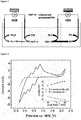
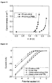
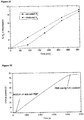
- Figure 2 shows how the peak current for both the oxidation and reduction events associated with this wave vary with the square root of the scan rate: the linear trend observed indicates that both these processes are limited only by diffusion on a Pt electrode (see also Figure 3 ). Based on the position of the OER catalytic wave (onset approx.
- These electrodes were then connected to a standard 3-electrode potentiostat as follows; one electrode functioned as the working electrode, whilst the other was connected to both the reference and counter electrode inputs on the potentiostat, giving a "floating reference electrode” configuration. This allowed us to monitor the current produced at fixed potential differences across the cell.
- This di-protonated, 2-electron reduced form of the PEB, H 5 Mo 12 PO 40 is remarkably stable to re-oxidation in air, either in aqueous solution at pH 0.3, or in the solid state after the water from the electrolyzed solution has been allowed to evaporate. Indeed, after standing in a beaker open to air under ambient laboratory conditions for 25 days, a solution of H 5 Mo 12 PO 40 in water appeared indistinguishable from a freshly prepared solution of the two-electron reduced PEB by both UV-Vis and 31 P NMR spectroscopies.
- H 5 Mo 12 PO 40 served as an excellent visual marker for any leakage of the PEB through the Nafion membrane, which would effectively "short-circuit" the cell, causing unproductive PEB oxidation/reduction events without any accompanying OER or HER. No such leakage was detected, even after storing the reduced PEB in the working electrode compartment for 5 weeks.
- this might mean allowing a high-surface area WO 3 photoanode to sit in sunlight for the majority of the daylight hours, slowly generating O 2 (which can be allowed to escape to the atmosphere) and H 5 Mo 12 PO 40 (separated by a Nafion membrane in the cathode compartment. During this time, no hydrogen is made, and so there is no explosion risk and no need for any compression or other H 2 -storage apparatus to be operational.
- the mediator of the invention in an oxygen generating reaction is expected to increase the oxygen evolution rate by around 10 times.
- Using the mediator of the invention in a hydrogen generating reaction is expected to increase the oxygen evolution rate by around 30 times.
- the application of a small bias to a hydrogen evolving cell, such as described herein, would release all the hydrogen for storage in a considerably quicker time frame than would be expected for a standard water-splitting cell. Accordingly the HER catalyst and H 2 compression equipment would only have to run for very short periods, greatly increasing the lifespan of these components.
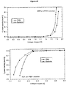
- Figure 14 shows the current-density vs . potential curves for the HER in a benzoylated cellulose-membrane H-cell on carbon electrodes with and without the use of a proton-electron buffer in a two-electrode configuration. The potential values that are reported were corrected for solution ohmic losses.
- the electrode performing the HER in 1 M H 3 PO 4 ) was designated as the working electrode. This was a glassy carbon button electrode of area 0.071 cm 2 .
- the counter electrode was a large area strip of carbon felt. The counter electrode was either placed in 0.5 M PEB/PEB* ("with PEB") or 1 M H 3 PO 4 ("without PEB").
- Figure 12 shows current-potential curves (not compensated for solution resistance) for the HER under various conditions in a Nafion-membrane H-cell.
- the electrode performing the HER in 1 M H 3 PO 4
- the counter electrode for the Pt experiments was a large area Pt mesh, and for the carbon experiments it was a large area strip of carbon felt.
- the counter electrode was either placed in 0.5 M PEB/PEB* ("with PEB") or 1 M H 3 PO 4 ("without PEB").
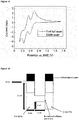
- the first reduced state of (H 3 O + )[H 2 Mo 12 PO 40 ] - in aqueous solution is the 2-electron reduced species (H 3 O + )[H 4 MO 12 PO 40 ] - , the redox wave corresponding to which is at ca. 0.9 V in Figure 2 (Maeda et al.; Tanaka et al.).
- Figure 2 shows how the peak current for the anodic part of this wave varies with the square root of the scan rate: the linear trend observed indicates that this process involves solution-phase species under diffusion control.
- a two-compartment cell similar to the one shown in Figure 1 was charged on one side with a 0.5 M aqueous solution of yellow fully-oxidised phosphomolybdic acid and on the other side with a 1 M solution of H 3 PO 4 .
- the two compartments of the H-cell were separated by a thin Nafion membrane, so that cations (in this case protons) could travel freely between the compartments, but the movement of anions (especially the PEB anions, which are of the general formula [H x Mo 12 PO 40 ] - ) across the membrane was greatly attenuated.
- PEB* The protonated and reduced form of the PEB (hereafter termed PEB*), could be subsequently re-oxidised to (H 3 O + )[H 2 Mo 12 PO 40 ] - in a three electrode configuration as described above by applying potentials anodic of the first redox wave in Figure 2A (+1.1 V vs. NHE).
- FIG. 2A Anodic of the first redox wave in Figure 2A (+1.1 V vs. NHE).
- bubbles of hydrogen were visible at the counter electrode ( vide infra ).
- the solution had returned to its original yellow colour, the pH was unchanged and H 2 production at the counter electrode ceased.
- the re-oxidised PEB solution had a UV-Vis spectrum identical to fresh (H 3 O + )[H 2 Mo 12 PO 40 ] - , indicating that no substantial decomposition of the PEB had occurred during cycling to the reduced and protonated form.
- Samples of PEB* were stored under air or under argon for various lengths of time before being re-oxidised, and the charges that could be extracted from these samples were compared to the charges originally passed in reducing (H 3 O + )[H 2 Mo 12 PO 40 ] - to PEB*. It was found that during cycling of PEB to PEB* and then immediately back to PEB under air ( i.e .
- PEB* was slowly re-oxidised, such that after 3 weeks storage under air in a sealed container, 95% of the charge originally stored in PEB* could be recovered for H 2 production, and after 8 months in a sealed container under air, 72% of the charge could be recovered.
- a solution of PEB* was stirred in a container open to air for 2 weeks, after which time 98% of the charge originally stored in PEB* could be recovered.
- Phosphomolybdic acid could also be oxidised and reduced several times without any degradation being apparent, and without any obvious decline in its ability to decouple the OER from the HER.
- analysis of samples of the PEB in various charge states by mass spectrometry showed that the PEB does not undergo decomposition or degradation when it is reduced and re-oxidised (Miras et al.).
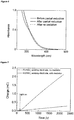
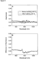
- Figure 10 gives a comparison of the UV-vis spectra of a sample of 0.5 M (H 3 O + )[H 2 Mo 12 PO 40 ] - in water before and after reduction to a 50:50 mix of (H 3 O + )[H 2 Mo 12 PO 40 ] - and (H 3 O + )[H 4 Mo 12 PO 40 ] - , along with a spectrum of the subsequently re-oxidised (H 3 O + )[H 2 Mo 12 PO 40 ] - solution. All these solutions were diluted to 5.0 ⁇ 10 5 M with water immediately before spectrum acquisition.
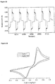
- Figure 15 shows the comparison of the CV of 0.5 M phosphomolybdic acid (solid line) after one full cycle from +1.7 V to +0.1 V ( vs. NHE) and after 500 such cycles (dashed line).
- a three-electrode, single compartment setup was used, with a 2 mm diameter Pt disc working electrode, Pt mesh counter electrode and an Ag/AgCl reference electrode at a scan rate of 100 mVs - 1, without any i R compensation.
- Figure 16 is a schematic of the H-cell used to determine the permeability of a benzoylated cellulose membrane to H 2 .
- the anodic and cathodic overpotentials can be reduced by employing catalysts on the electrodes.
- catalysts on the electrodes For example, the use of RuO 2 as an extremely effective anode for the OER could afford a current density of 0.1 A cm -1 (at room temperature and at pH 1) at around +1.5 V vs. NHE (Lodi et al.; Burke et al.), which compares to around +2.05 V for the same current density on Pt. Meanwhile, the resistance from the solution and membrane can be minimised by decreasing the distance between the electrodes and optimising the membrane thickness.
- E pH is in the region of 36 mV, which is negligible in comparison to size of the chief source of error, i R solvent.
- Faradaic efficiency for both oxygen evolution and hydrogen evolution are 1, we compared the overall system efficiency for electrochemically-driven water splitting on Pt electrodes by comparing the current densities obtained at a given voltage. Using the data provided by the Figures herein, we obtain an overall efficiency of 79% for the PEB system (relative to a single-step process where OER and HER remain coupled) for the production of hydrogen and oxygen at 100 mAcm -2 on Pt electrodes.
- Gas chromatography headspace analysis was conducted in air-tight H-cells ( Figure 9 ) in a two-electrode configuration, using an Agilent Technologies 7890A GC system with a pneumatically operated automatic gas sampling valve to monitor the gases evolved.
- the cells were connected to the GC system using bespoke airtight glass-to-metal adapters and copper tubing of 1 ⁇ 8 inch internal diameter.
- the column used was a 30 metre-long 0.320 mm widebore HP-molecular sieve column (Agilent).
- the GC oven temperature was set to 40 oC and the carrier gas was Ar.
- the GC system was calibrated for O 2 and H 2 using certified standards of these gases at a range of volume % in argon supplied by CK Gas Products Limited (UK).
- the GC was calibrated for both static and flushed gas samples ( vide infra ).
- Total H-cell/GC system headspaces were calculated by filling the cells with water at room temperature and adding on volumes for the GC sample loop (0.25 mL) and connecting tubing to, from and within the GC system. Typical headspaces were on the order of 95 mL. Two different experimental variations were used as shown in Figure 9 , and O 2 and H 2 headspace concentrations were determined using both methods.
- Faradaic efficiencies were then calculated by taking the ratio of gas volume % based on the charge passed to the gas volume % measured by GC. All H 2 determinations were performed at least twice, and average Faradaic efficiencies were 100.5% ( ⁇ 2%) for Pt and 99.1% ( ⁇ 2%) for carbon electrodes respectively. The main source of error was the estimation of the cell headspace ( ⁇ 1 mL). A representative trace is given in Figure 13 .
- Figure 13 shows the representative trace of cumulative H 2 build-up in the cell headspace during hydrogen evolution on carbon electrodes.
- a two-electrode set-up was used at an effective potential difference of 1.4 V.
- the expected volume % of H 2 in the headspace was calculated from the charge passed during electrolysis ("H 2 calculated”: top line). Electrolysis was terminated at 480 minutes.
- the volume % of H 2 in the headspace (“H 2 measured”: bottom line) was determined by the GC system in a static cell configuration, with sampling every 2 hours. The time lag between when the hydrogen is made electrolytically and when it is measured by the GC is due to the slow effusion of H 2 through the narrow tubing in the GC system under these static conditions.
- the increased mass of O 2 was found to give a long time lag between gas production and gas detection. Typically, this resulted in only 50% of the expected gas being detected within 8 hours of the end of electrolysis.
- a flushed cell configuration was used. This involved passing a certain amount of charge, before terminating the electrolysis reaction and then flushing the contents of the cell headspace through the sample loop using a low-pressure Ar feed. This precluded incremental measurements of the gas concentrations in the headspace, as the headspace contents were flushed to the external environment within a few seconds.
- O 2 determinations were performed at least three times, and average Faradaic efficiencies were 100.2% ( ⁇ 5%) for Pt and ⁇ 5% for carbon electrodes respectively.
- the larger uncertainty found for O 2 quantification reflects both errors in the estimation of the cell headspace and the error in the correction applied for the air leak into the GC system during sampling.
- the GC system is inherently less sensitive to oxygen (when using Ar as the carrier gas) than it is to hydrogen.
- the working electrode was a 0.031 cm 2 area platinum disc electrode and the combined counter/reference electrode (two-electrode configuration) was a large area Pt mesh.
- the two chambers of the H-cell were separated by a Nafion membrane, so that cations (here only protons) could travel freely between compartments, but the movement of anions (especially the PEB anions) was greatly attenuated.
- Figure 11 shows how the current density through such a cell varies with the magnitude of the effective applied voltage (as set on the working electrode in the 1 M H 3 PO 4 ). Also shown for comparison is the current density curve for the same cell set-up, but where both chambers were filled with 1 M H 3 PO 4 , i.e. using no PEB. It is apparent that much greater current densities are obtained at a given voltage when the PEB is used, whether the voltage applied is positive (oxidation of water at the nominal working electrode, Figure 11 ) or negative (reduction of protons at the working electrode). In support of this, steadily bubbling from the working electrode was observed when the counter electrode compartment was filled with PEB and effective voltages above +1 V or below -1 V were applied to the working electrode.
- the theoretical efficiency loss (i.e . the loss encountered if all the losses listed in equation 5 in the main text are negligibly small) compared to the one step system is simply the energy penalty imposed by having to oxidize/reduce the mediator, i,e. 0.06 V.
- This equates to a theoretical maximum efficiency of 97% for the two-step system compared to the one step system.
- the fact that the current system falls short of this is due mainly to residual uncorrected resistance in the cell design, which effects the two-step system twice as much as the one-step system.
- Phosphomolybdic acid is a comparatively large molecule (MW ⁇ 1800, effective cross sectional area ⁇ 1 nm 2 )(Himeno et al.).
- MW ⁇ 1800 effective cross sectional area ⁇ 1 nm 2
- This allied to the fact that a PEB allows H 2 and O 2 production to be separated in time, means that pure H 2 and O 2 streams can be obtained from aqueous solutions using membranes that simply retain the PEB in one compartment of the cell.
- This membrane proved very effective at preventing the mixing of a 50:50 solution of PEB:PEB* in one compartment and 1 M H 3 PO 4 in the other over the time-course of several days.
- Current-potential ( i -V) analysis of this cell in a two electrode configuration with carbon electrodes as before produced curves almost identical to those obtained for the same electrode set with a Nafion separation membrane, showing that cell performance was not impaired by replacing Nafion with cellulose.
- temporally separated OER and HER means that new types of membrane (i.e . types that might not be as gas-impermeable as Nafion), can be considered for use in proton exchange membrane electrolysers (PEMEs) without dangerous mixes of H 2 and O 2 developing in the cell headspace.
- PEMEs proton exchange membrane electrolysers
- the H-cell shown in Figure 16 was used.
- the headspace for the two compartments was not linked, such that the only route for cross-over for gases within the cell was for the gases in the headspace on one side to dissolve in the liquid present in that chamber and then diffuse through the membrane into the liquid in the other chamber, and thence diffuse into the headspace of this other chamber.
- One side of this cell was filled with 30 mL of yellow oxidised PEB and was bubbled with pure H 2 gas for 100 minutes.
- the headspace of the PEB chamber of the cell was sealed off and the other chamber of the cell was filled with a non-degassed solution of 1 M H 3 PO 4 .
- the headspace of this 1 M H 3 PO 4 chamber was purged very briefly (around 10 seconds) with Ar to remove excess oxygen, before the outlet of this chamber was connected to the GC.
- the headspace was then sampled every 10 minutes without any re-circulating of gas or positive pressure of flow gas, in order to ensure that the pressure in the headspace of the 1 M H 3 PO4 chamber remained at or below the pressure of the H 2 -containing chamber.
- H 2 was detected in the 1 M H 3 PO 4 chamber headspace after 30 minutes.
- hydrogen could be detected by the GC using this method within 20 minutes.
- the membrane is considered to be essentially freely permeable to H 2 , in line with its large pore size and the manufacturers specification. Likewise, by the same reasoning, it is to be expected that the membrane is also freely permeable to O 2 .
- Hydrogen is explosive in air at concentrations between 4% and 74% by volume. Hence it is recommended compressing and removing the majority of the air in the headspace of a working electrolyser before H 2 production is commenced: this should not be too hard, as the H 2 itself will have to be compressed and removed for use anyway, and the vast majority of the O 2 produced can still be vented to the air.
- the earliest fractions of H 2 that are collected and which would be contaminated with O 2 could be diverted, such that the later fractions were not contaminated by O 2 during this "cross-over" phase.
- Figure 17A is a comparison of a sample of fully oxidised 0.5 M phosphomolybdic acid before (bottom line at 600 nm) and after (top line at 600 nm) bubbling with H 2 for 100 minutes and then being stirred under a hydrogen atmosphere for a further 14 h.
- Figure 17B is the difference spectrum (after bubbling - before bubbling) of the spectra shown in Figure 17A . All these solutions were diluted to 1.0 ⁇ 10 -3 M with water immediately before spectrum acquisition. The discontinuity in the data around 750 nm is due to the change-over of the detector at this wavelength.
- Figure 18 is Comparison of the CV of 0.5 M phosphomolybdic acid under air (solid line) and under H 2 (dashed line).
- a three-electrode, single compartment setup was used, with a 2 mm diameter Pt disc working electrode, carbon cloth counter electrode and an Ag/AgCl reference electrode at a scan rate of 100 mVs -1 , without any i R compensation
- MS data were collected in aqueous medium using a Q-trap, time-of-flight MS (Maxis Impact) instrument supplied by Bruker Daltonics Ltd.
- the detector was a time-of-flight, micro-channel plate detector and all data was processed using the Bruker Daltonics Data Analysis 4.1 software, whilst simulated isotope patterns were investigated using Bruker Isotope Pattern software and Molecular Weight Calculator 6.45.
- the calibration solution used was Agilent ES tuning mix solution, Recorder No. G2421A, enabling calibration between approximately 300 m/z and 5000 m/z. This solution was diluted 60:1 with MeCN. Samples were introduced into the MS via direct injection at 100 ⁇ L/h.
- FIG. 19 is a schematic of a quinone-based mediator approach to generating hydrogen and oxygen by water-splitting.
- Figure 19 shows a schematic of a two cells system for generating hydrogen (top cell) and oxygen (bottom cell using a 1,4-benzoquinone-2-sulfonate and its reduced partner, 1,4-dihydro-benzene-2-sulfonate.
- the mediator 1,4-benzoquinone-2-sulfonate was used in a hydrogen evolving cell at 0.5 M at pH 0.77 in a phosphate buffer.
- the mediator phosphomolybdic acid was used in a hydrogen evolving cell at 0.5 M at pH 0.35 in a phosphate buffer.
- the cell made use of a Pt working electrode, a carbon reference and counter electrode and a Nafion membrane.
- the mediator was placed in the electrochemical cell at the working electrode side of the membrane.
- Figure 20 shows the change in current with voltage drop for hydrogen evolution experiments, comparing 1,4-benzoquinone-2-sulfonate with PMA, where PMA is phosphomolybdic acid.
- Figure 21 shows the change in the amount of hydrogen located in the headspace of the electrochemical cell used in the experiment above. After a reaction time of ca. 350 mins 94.9% of the theoretical amount of hydrogen available had been produced form the system.
- Figure 22 shows the change in total charge passed in a hydrogen evolving cell before and after the mediator 1,4-benzoquinone-2-sulfonate is added.
- the cell comprises a Pt working electrode, and a carbon felt counter and reference electrode.
- the voltage was - 0.8 V.
- the current observed was at a background level only. Addition of the mediator results in an increase in the current passed by about 78 times. Once the mediator is completely oxidised, the total current does not increase. The recorded data showed that 98.3% of the theoretical amount of charge had been passed.
- Figures 23 and 24 show that the mediator 1,4-benzoquinone-2-suifonate retains its activity over many oxidation and reduction (CV) cycles.
- Figure 24 shows that the electrochemical reactivity of the mediator 1,4-benzoquinone-2-sulfonate remains substantially the same after 500 CV cycles.
- the CV experiments were performed with a 1:1 mixture of 1,4-benzoquinone-2-sulfonate and 1,4-dihydroxy-2-sulfonate in a phosphate buffer at pH 1, with a glassy carbon working electrode, a Pt counter electrode and a silver/silver chloride reference electrode.
- the Fe 2+ /Fe 3+ couple is unsuitable as a PEB on account of the small size of the ions (which means benzoylated cellulose membranes will not retain them in one side of the cell), their positive charge (which means that the ions may permeate through Nafion membranes, which they are in any case known to attack) and because Fe 2+ salts are not stable in aqueous solution, and tend to spontaneously re-oxidise to Fe 3+ salts (hence aerial re-oxidisation of the Fe 2+ would compete with electrochemical re-oxidation, reducing yields of H 2 ). For these reasons, neither of the above couples can compete with phosphomolybdic acid as an effective and stable PEB.
- the compartments were separated by a Nafion membrane.
- the Nal compartment was further equipped with a Pt mesh working electrode and an Ag/AgCl reference electrode, whilst the NaH 2 PO 4 compartment contained a Pt mesh counter electrode.
- Bulk electrolysis was commenced at +1.0 V vs. Ag/AgCl. Soon after the initiation of the electrolysis, the working electrode compartment went yellow, and then got progressively darker.
Landscapes
- Chemical & Material Sciences (AREA)
- Engineering & Computer Science (AREA)
- Chemical Kinetics & Catalysis (AREA)
- Electrochemistry (AREA)
- Materials Engineering (AREA)
- Metallurgy (AREA)
- Organic Chemistry (AREA)
- Inorganic Chemistry (AREA)
- Electrolytic Production Of Non-Metals, Compounds, Apparatuses Therefor (AREA)
Applications Claiming Priority (2)
| Application Number | Priority Date | Filing Date | Title |
|---|---|---|---|
| GBGB1119283.8A GB201119283D0 (en) | 2011-11-08 | 2011-11-08 | Apparatus and methods for the electrochemical generation of oxygen and/or hydrogen |
| PCT/GB2012/052784 WO2013068754A1 (en) | 2011-11-08 | 2012-11-08 | Apparatus and methods for the electrochemical generation of oxygen and/or hydrogen |
Publications (2)
| Publication Number | Publication Date |
|---|---|
| EP2776606A1 EP2776606A1 (en) | 2014-09-17 |
| EP2776606B1 true EP2776606B1 (en) | 2020-03-25 |
Family
ID=45421460
Family Applications (1)
| Application Number | Title | Priority Date | Filing Date |
|---|---|---|---|
| EP12790944.8A Active EP2776606B1 (en) | 2011-11-08 | 2012-11-08 | Method for the electrochemical generation of oxygen and hydrogen |
Country Status (8)
| Country | Link |
|---|---|
| US (1) | US10604852B2 (enExample) |
| EP (1) | EP2776606B1 (enExample) |
| JP (1) | JP6101276B2 (enExample) |
| KR (1) | KR101988686B1 (enExample) |
| CN (1) | CN104053821B (enExample) |
| CA (1) | CA2854715C (enExample) |
| GB (1) | GB201119283D0 (enExample) |
| WO (1) | WO2013068754A1 (enExample) |
Cited By (1)
| Publication number | Priority date | Publication date | Assignee | Title |
|---|---|---|---|---|
| EP4301899A4 (en) * | 2021-03-01 | 2025-06-25 | Verdagy, Inc. | Systems and methods for producing hydrogen gas |
Families Citing this family (37)
| Publication number | Priority date | Publication date | Assignee | Title |
|---|---|---|---|---|
| EP3791834B1 (en) * | 2012-09-17 | 2026-03-04 | President And Fellows Of Harvard College | Soft exosuit for assistance with human motion |
| CN103800979B (zh) | 2013-06-19 | 2018-05-04 | 林信涌 | 保健气体产生器 |
| WO2014204772A1 (en) * | 2013-06-20 | 2014-12-24 | The Regents Of The University Of California | Self-biased and sustainable microbial electrohydrogenesis device |
| GB201416062D0 (en) * | 2014-09-11 | 2014-10-29 | Univ The Glasgow | Hydrogen generation |
| JP6388820B2 (ja) * | 2014-11-10 | 2018-09-12 | 国立研究開発法人産業技術総合研究所 | 光エネルギーの利用方法および光エネルギーの利用装置 |
| JP6418906B2 (ja) * | 2014-11-10 | 2018-11-07 | 国立研究開発法人産業技術総合研究所 | 光エネルギーの利用方法および光エネルギーの利用装置 |
| DE102015206288A1 (de) * | 2015-04-09 | 2016-10-13 | Robert Bosch Gmbh | Vorrichtung, System und Verfahren zum Gewinnen von Wasserstoff aus Wasser unter Verwendung eines Arbeitsstoffs |
| CN105420748B (zh) * | 2015-11-18 | 2018-01-12 | 复旦大学 | 一种基于三电极体系的两步法电解水制氢的方法及装置 |
| CN105463497B (zh) * | 2015-11-18 | 2018-01-12 | 复旦大学 | 一种可以电解水制取氢气的电池装置 |
| EP3402912A4 (en) * | 2016-01-15 | 2019-10-23 | Skyre, Inc. | HYDROGEN SYSTEM AND METHOD OF OPERATION |
| CN105821436B (zh) * | 2016-05-09 | 2018-07-24 | 复旦大学 | 一种基于三电极体系的双电解槽两步法氯碱电解方法及装置 |
| JP2018119204A (ja) * | 2016-06-16 | 2018-08-02 | パナソニックIpマネジメント株式会社 | 水素脱離方法および脱水素装置 |
| WO2019118450A1 (en) * | 2017-12-11 | 2019-06-20 | Arizona Board Of Regents On Behalf Of The University Of Arizona | Enhanced water electrolysis with protic co-catalysts |
| CN107051565A (zh) * | 2017-05-24 | 2017-08-18 | 中国科学院化学研究所 | 一种高性能碱式碳酸盐类电解水催化剂及其制备方法与应用 |
| CN107815699B (zh) * | 2017-11-10 | 2019-03-19 | 上海应用技术大学 | 一种POMs-C复合材料、制备方法和应用 |
| GB201801170D0 (en) | 2018-01-24 | 2018-03-07 | Univ Court Univ Of Glasgow | Use of polyoxometalate mediators |
| IL258252A (en) * | 2018-03-20 | 2018-06-28 | Technion Res & Development Found Ltd | System and method for generation of gases |
| FR3079529B1 (fr) | 2018-04-03 | 2024-04-26 | Ergosup | Procede electrochimique de production d'hydrogene gazeux sous pression par electrolyse puis par depolarisation |
| FR3079530B1 (fr) | 2018-04-03 | 2024-04-26 | Ergosup | Procede electrochimique de production d'hydrogene gazeux sous pression par electrolyse puis par conversion electrochimique |
| US11447882B2 (en) * | 2018-04-12 | 2022-09-20 | University Of Houston System | Methods for making bifunctional porous non-noble metal phosphide catalyst for overall water splitting, electrodes for overall water splitting, and methods for electrocatalytic water splitting |
| CN109321936B (zh) * | 2018-11-29 | 2020-06-02 | 厦门大学 | 一种基于液流氧化还原媒介分步电解水制氢的装置和方法 |
| DE102019104401A1 (de) * | 2019-01-22 | 2020-07-23 | Deutsches Zentrum für Luft- und Raumfahrt e.V. | Elektrolyseur und Verfahren zum Aufspalten von Wasser |
| US11203812B2 (en) * | 2019-02-22 | 2021-12-21 | New York University | Methods and electrochemical cells for redox mediated hydrogen production |
| US11313044B2 (en) * | 2019-08-20 | 2022-04-26 | Deutsches Zentrum fuer Loft- und Raumfahrt e.V. | Electrolyzer and method for splitting water |
| KR102250826B1 (ko) | 2019-09-20 | 2021-05-11 | (주)골드앤스노우 월드와이드 | 수소 기체 발생 조성물 및 수소 기체 포집 나노구조체 |
| DE102020110633A1 (de) * | 2020-04-20 | 2021-10-21 | Deutsches Zentrum für Luft- und Raumfahrt e.V. | Verfahren und Apparatur zur elektrochemisch unterstützten thermochemischen Spaltung von Wasser und Kohlendioxid |
| AU2021275780A1 (en) * | 2020-05-20 | 2023-01-05 | President And Fellows Of Harvard College | Forward osmosis driven by electrolysis |
| KR102895243B1 (ko) * | 2020-06-22 | 2025-12-03 | 현대자동차주식회사 | 수전해 시스템 |
| CN113026044B (zh) * | 2021-01-28 | 2022-01-07 | 江西津晶智美环保科技有限公司 | 一种三室二电源全分解水电解装置及方法 |
| JP2023016252A (ja) * | 2021-07-21 | 2023-02-02 | 株式会社日立製作所 | 光化学反応システム及び光化学反応方法 |
| EP4409056A2 (en) * | 2021-09-28 | 2024-08-07 | Verdagy, Inc. | Systems and methods to make hydrogen gas with a steady-state ph differential |
| CN114032571B (zh) * | 2021-10-13 | 2022-12-09 | 西安交通大学 | 一种耦合分步电解水装置和水系电池的一体化系统与方法 |
| WO2024013308A2 (en) | 2022-07-13 | 2024-01-18 | The University Court Of The University Of Glasgow | Method of reducing nitro compounds |
| CN116609408B (zh) * | 2023-04-28 | 2026-03-24 | 中国科学院宁波材料技术与工程研究所 | 一种原位测氢的电还原-电氧化复合电极及其制备方法与应用 |
| WO2025080916A2 (en) * | 2023-10-12 | 2025-04-17 | Regents Of The University Of Michigan | Method for reversible ph-swing flow cells for co2 capture |
| WO2025132521A1 (en) | 2023-12-19 | 2025-06-26 | Fundación Centro De Investigación Cooperativa De Energías Alternativas Cic Energigune Fundazioa | Electrochemical system comprising a gallium redox mediator and uses thereof |
| WO2025245447A1 (en) * | 2024-05-24 | 2025-11-27 | Massachusetts Institute Of Technology | Electrochemical hydrogen pumping coupled with catalytic membrane reactor and its applications |
Family Cites Families (21)
| Publication number | Priority date | Publication date | Assignee | Title |
|---|---|---|---|---|
| GB1602963A (en) * | 1977-04-13 | 1981-11-18 | Nat Res Dev | Catalytic process for photo-oxidation of water |
| US4492743A (en) * | 1982-10-15 | 1985-01-08 | Standard Oil Company (Indiana) | Multilayer photoelectrodes and photovoltaic cells |
| JPS6447890A (en) * | 1987-08-13 | 1989-02-22 | Kenzo Yamaguchi | Electrolytic synthesis method |
| US5389356A (en) * | 1993-01-05 | 1995-02-14 | Utah State University Foundation | Compounds and methods for generating oxygen free radicals used in general oxidation and reduction reactions |
| US7387719B2 (en) * | 2001-04-24 | 2008-06-17 | Scimist, Inc. | Mediated electrochemical oxidation of biological waste materials |
| CA2445717C (en) * | 2001-05-02 | 2010-07-13 | Japan Techno Co., Ltd. | Hydrogen-oxygen gas generator and hydrogen-oxygen gas generating method thereof |
| US6712949B2 (en) * | 2001-07-22 | 2004-03-30 | The Electrosynthesis Company, Inc. | Electrochemical synthesis of hydrogen peroxide |
| AU2002367842A1 (en) * | 2001-10-22 | 2003-11-11 | The C And M Group, Llc | Mediated electrochemical oxidation of organic waste materials |
| AU2003237113A1 (en) * | 2002-04-26 | 2003-11-10 | The C And M Group, Llc | Mediated electrochemical oxidation process used as a hydrogen fuel generator |
| WO2004112214A2 (en) * | 2003-05-30 | 2004-12-23 | The Arizona Board Of Regents Acting On Behalf Of Arizona State University | Methods for use of a photobiofuel cell in production of hydrogen and other materials |
| US7208244B2 (en) | 2003-10-15 | 2007-04-24 | Auburn University | Di-ruthenium-substituted polyoxometalate electrocatalyst and method of oxygen generation |
| JP5114823B2 (ja) * | 2004-05-31 | 2013-01-09 | 日産自動車株式会社 | 光電気化学電池 |
| US20070012578A1 (en) | 2005-06-30 | 2007-01-18 | Akzo Nobel N.V. | Chemical process |
| WO2007027876A2 (en) * | 2005-08-31 | 2007-03-08 | Battelle Memorial Institute | Power device and oxygen generator |
| GB0608079D0 (en) | 2006-04-25 | 2006-05-31 | Acal Energy Ltd | Fuel cells |
| KR20100100752A (ko) | 2007-09-07 | 2010-09-15 | 에이. 코헨 빈요민 | 하나의 소스로부터 산소 및/또는 수소를 발생시키기 위한 필터재 |
| EP2151512A1 (en) | 2008-08-01 | 2010-02-10 | Total Petrochemicals Research Feluy | Fibers and nonwovens with increased surface roughness. |
| FI121928B (fi) | 2008-10-08 | 2011-06-15 | Teknillinen Korkeakoulu | Sähköntuottojärjestelmä |
| US8822367B2 (en) | 2009-03-17 | 2014-09-02 | Emory University | Polyoxometalate water oxidation catalysts and methods of use thereof |
| WO2011053250A1 (en) * | 2009-10-26 | 2011-05-05 | Agency For Science, Technology And Research | Photoelectrode with a polymer layer |
| GB201017421D0 (en) | 2010-10-14 | 2010-12-01 | Acal Energy Ltd | Cell |
-
2011
- 2011-11-08 GB GBGB1119283.8A patent/GB201119283D0/en not_active Ceased
-
2012
- 2012-11-08 EP EP12790944.8A patent/EP2776606B1/en active Active
- 2012-11-08 CA CA2854715A patent/CA2854715C/en active Active
- 2012-11-08 KR KR1020147015151A patent/KR101988686B1/ko active Active
- 2012-11-08 US US14/357,066 patent/US10604852B2/en active Active
- 2012-11-08 CN CN201280066403.5A patent/CN104053821B/zh active Active
- 2012-11-08 WO PCT/GB2012/052784 patent/WO2013068754A1/en not_active Ceased
- 2012-11-08 JP JP2014539413A patent/JP6101276B2/ja active Active
Non-Patent Citations (1)
| Title |
|---|
| None * |
Cited By (1)
| Publication number | Priority date | Publication date | Assignee | Title |
|---|---|---|---|---|
| EP4301899A4 (en) * | 2021-03-01 | 2025-06-25 | Verdagy, Inc. | Systems and methods for producing hydrogen gas |
Also Published As
| Publication number | Publication date |
|---|---|
| JP2014532812A (ja) | 2014-12-08 |
| KR20140093706A (ko) | 2014-07-28 |
| US20140318979A1 (en) | 2014-10-30 |
| KR101988686B1 (ko) | 2019-06-12 |
| EP2776606A1 (en) | 2014-09-17 |
| WO2013068754A1 (en) | 2013-05-16 |
| US10604852B2 (en) | 2020-03-31 |
| CA2854715A1 (en) | 2013-05-16 |
| JP6101276B2 (ja) | 2017-03-22 |
| CN104053821A (zh) | 2014-09-17 |
| CA2854715C (en) | 2021-04-27 |
| CN104053821B (zh) | 2018-09-04 |
| GB201119283D0 (en) | 2011-12-21 |
Similar Documents
| Publication | Publication Date | Title |
|---|---|---|
| EP2776606B1 (en) | Method for the electrochemical generation of oxygen and hydrogen | |
| Moon et al. | Solar-driven H 2 O 2 production via cooperative auto-and photocatalytic oxidation in fine-tuned reaction media | |
| Vermaas et al. | Photo-assisted water splitting with bipolar membrane induced pH gradients for practical solar fuel devices | |
| Arai et al. | Photoelectrochemical reduction of CO 2 in water under visible-light irradiation by a p-type InP photocathode modified with an electropolymerized ruthenium complex | |
| Symes et al. | Decoupling hydrogen and oxygen evolution during electrolytic water splitting using an electron-coupled-proton buffer | |
| US20170297913A1 (en) | Hydrogen Generation | |
| Kim et al. | Solar desalination coupled with water remediation and molecular hydrogen production: a novel solar water-energy nexus | |
| Hisatomi et al. | Recent advances in semiconductors for photocatalytic and photoelectrochemical water splitting | |
| Chae et al. | A perspective on practical solar to carbon monoxide production devices with economic evaluation | |
| EP3234224B1 (en) | Filter-press photoelectrochemical water oxidation and co2 reduction cell | |
| Lopes et al. | An innovative photoelectrochemical lab device for solar water splitting | |
| JP6774165B2 (ja) | 光化学反応デバイス、それに用いられる酸化反応用電極及び還元反応用電極 | |
| US20130001094A1 (en) | Lanthanide-Mediated Water Splitting Process for Hydrogen and Oxygen Generation | |
| Ng et al. | Exploration and optimisation of poly (2, 2′-bithiophene) as a stable photo-electrocatalyst for hydrogen production | |
| JP6418906B2 (ja) | 光エネルギーの利用方法および光エネルギーの利用装置 | |
| Peljo et al. | Oxygen reduction at a water-1, 2-dichlorobenzene interface catalyzed by cobalt tetraphenyl porphyrine–A fuel cell approach | |
| Bradley et al. | Electrocatalytic reduction of carbon dioxide at illuminated p-type silicon semiconduccting electrodes | |
| Mitoraj et al. | Mechanism of aerobic visible light formic acid oxidation catalyzed by poly (tri-s-triazine) modified titania | |
| CN115725985A (zh) | 一种光电化学制氯方法及其检测装置和应用 | |
| Takasugi et al. | Significance of an anion effect in the selective oxidation of Ce3+ to Ce4+ over a porous WO3 photoanode | |
| Schanz et al. | Anodic peroxide production for advanced oxidation processes with different metal oxide electrodes in carbonate electrolytes | |
| Yoneyama et al. | Heterogeneous reactions of nitrogen monoxide on titanium dioxide photocatalysts in solutions | |
| Sikorski et al. | Dye-sensitized photoelectrochemical cell combining a MOF catalyst and cobaltocene CoCpCp* as redox mediator for CO 2 reduction | |
| Villagra et al. | Surface modification of rhodium-doped strontium titanate by adsorption of cobalt clathrochelates for water photodissociation | |
| 원승환 | Charge-Transfer Pathways in Semiconductor Photoelectrodes and Their Impact on the Selectivity of Homogeneous Chemical Reactions |
Legal Events
| Date | Code | Title | Description |
|---|---|---|---|
| PUAI | Public reference made under article 153(3) epc to a published international application that has entered the european phase |
Free format text: ORIGINAL CODE: 0009012 |
|
| 17P | Request for examination filed |
Effective date: 20140522 |
|
| AK | Designated contracting states |
Kind code of ref document: A1 Designated state(s): AL AT BE BG CH CY CZ DE DK EE ES FI FR GB GR HR HU IE IS IT LI LT LU LV MC MK MT NL NO PL PT RO RS SE SI SK SM TR |
|
| DAX | Request for extension of the european patent (deleted) | ||
| 17Q | First examination report despatched |
Effective date: 20160420 |
|
| STAA | Information on the status of an ep patent application or granted ep patent |
Free format text: STATUS: EXAMINATION IS IN PROGRESS |
|
| GRAP | Despatch of communication of intention to grant a patent |
Free format text: ORIGINAL CODE: EPIDOSNIGR1 |
|
| STAA | Information on the status of an ep patent application or granted ep patent |
Free format text: STATUS: GRANT OF PATENT IS INTENDED |
|
| INTG | Intention to grant announced |
Effective date: 20170713 |
|
| GRAJ | Information related to disapproval of communication of intention to grant by the applicant or resumption of examination proceedings by the epo deleted |
Free format text: ORIGINAL CODE: EPIDOSDIGR1 |
|
| STAA | Information on the status of an ep patent application or granted ep patent |
Free format text: STATUS: EXAMINATION IS IN PROGRESS |
|
| GRAP | Despatch of communication of intention to grant a patent |
Free format text: ORIGINAL CODE: EPIDOSNIGR1 |
|
| STAA | Information on the status of an ep patent application or granted ep patent |
Free format text: STATUS: GRANT OF PATENT IS INTENDED |
|
| INTC | Intention to grant announced (deleted) | ||
| INTG | Intention to grant announced |
Effective date: 20180328 |
|
| GRAJ | Information related to disapproval of communication of intention to grant by the applicant or resumption of examination proceedings by the epo deleted |
Free format text: ORIGINAL CODE: EPIDOSDIGR1 |
|
| STAA | Information on the status of an ep patent application or granted ep patent |
Free format text: STATUS: EXAMINATION IS IN PROGRESS |
|
| GRAP | Despatch of communication of intention to grant a patent |
Free format text: ORIGINAL CODE: EPIDOSNIGR1 |
|
| STAA | Information on the status of an ep patent application or granted ep patent |
Free format text: STATUS: GRANT OF PATENT IS INTENDED |
|
| INTC | Intention to grant announced (deleted) | ||
| INTG | Intention to grant announced |
Effective date: 20181220 |
|
| GRAJ | Information related to disapproval of communication of intention to grant by the applicant or resumption of examination proceedings by the epo deleted |
Free format text: ORIGINAL CODE: EPIDOSDIGR1 |
|
| STAA | Information on the status of an ep patent application or granted ep patent |
Free format text: STATUS: EXAMINATION IS IN PROGRESS |
|
| INTC | Intention to grant announced (deleted) | ||
| GRAP | Despatch of communication of intention to grant a patent |
Free format text: ORIGINAL CODE: EPIDOSNIGR1 |
|
| STAA | Information on the status of an ep patent application or granted ep patent |
Free format text: STATUS: GRANT OF PATENT IS INTENDED |
|
| RIC1 | Information provided on ipc code assigned before grant |
Ipc: C25B 15/08 20060101ALI20190903BHEP Ipc: C25B 1/00 20060101AFI20190903BHEP Ipc: C25B 5/00 20060101ALI20190903BHEP Ipc: C25B 1/10 20060101ALI20190903BHEP |
|
| INTG | Intention to grant announced |
Effective date: 20191008 |
|
| GRAS | Grant fee paid |
Free format text: ORIGINAL CODE: EPIDOSNIGR3 |
|
| GRAA | (expected) grant |
Free format text: ORIGINAL CODE: 0009210 |
|
| STAA | Information on the status of an ep patent application or granted ep patent |
Free format text: STATUS: THE PATENT HAS BEEN GRANTED |
|
| AK | Designated contracting states |
Kind code of ref document: B1 Designated state(s): AL AT BE BG CH CY CZ DE DK EE ES FI FR GB GR HR HU IE IS IT LI LT LU LV MC MK MT NL NO PL PT RO RS SE SI SK SM TR |
|
| REG | Reference to a national code |
Ref country code: GB Ref legal event code: FG4D |
|
| REG | Reference to a national code |
Ref country code: AT Ref legal event code: REF Ref document number: 1248658 Country of ref document: AT Kind code of ref document: T Effective date: 20200415 Ref country code: IE Ref legal event code: FG4D |
|
| REG | Reference to a national code |
Ref country code: DE Ref legal event code: R096 Ref document number: 602012068760 Country of ref document: DE |
|
| PG25 | Lapsed in a contracting state [announced via postgrant information from national office to epo] |
Ref country code: FI Free format text: LAPSE BECAUSE OF FAILURE TO SUBMIT A TRANSLATION OF THE DESCRIPTION OR TO PAY THE FEE WITHIN THE PRESCRIBED TIME-LIMIT Effective date: 20200325 Ref country code: NO Free format text: LAPSE BECAUSE OF FAILURE TO SUBMIT A TRANSLATION OF THE DESCRIPTION OR TO PAY THE FEE WITHIN THE PRESCRIBED TIME-LIMIT Effective date: 20200625 Ref country code: RS Free format text: LAPSE BECAUSE OF FAILURE TO SUBMIT A TRANSLATION OF THE DESCRIPTION OR TO PAY THE FEE WITHIN THE PRESCRIBED TIME-LIMIT Effective date: 20200325 |
|
| PG25 | Lapsed in a contracting state [announced via postgrant information from national office to epo] |
Ref country code: HR Free format text: LAPSE BECAUSE OF FAILURE TO SUBMIT A TRANSLATION OF THE DESCRIPTION OR TO PAY THE FEE WITHIN THE PRESCRIBED TIME-LIMIT Effective date: 20200325 Ref country code: GR Free format text: LAPSE BECAUSE OF FAILURE TO SUBMIT A TRANSLATION OF THE DESCRIPTION OR TO PAY THE FEE WITHIN THE PRESCRIBED TIME-LIMIT Effective date: 20200626 Ref country code: LV Free format text: LAPSE BECAUSE OF FAILURE TO SUBMIT A TRANSLATION OF THE DESCRIPTION OR TO PAY THE FEE WITHIN THE PRESCRIBED TIME-LIMIT Effective date: 20200325 Ref country code: SE Free format text: LAPSE BECAUSE OF FAILURE TO SUBMIT A TRANSLATION OF THE DESCRIPTION OR TO PAY THE FEE WITHIN THE PRESCRIBED TIME-LIMIT Effective date: 20200325 Ref country code: BG Free format text: LAPSE BECAUSE OF FAILURE TO SUBMIT A TRANSLATION OF THE DESCRIPTION OR TO PAY THE FEE WITHIN THE PRESCRIBED TIME-LIMIT Effective date: 20200625 |
|
| REG | Reference to a national code |
Ref country code: NL Ref legal event code: MP Effective date: 20200325 |
|
| REG | Reference to a national code |
Ref country code: LT Ref legal event code: MG4D |
|
| PG25 | Lapsed in a contracting state [announced via postgrant information from national office to epo] |
Ref country code: NL Free format text: LAPSE BECAUSE OF FAILURE TO SUBMIT A TRANSLATION OF THE DESCRIPTION OR TO PAY THE FEE WITHIN THE PRESCRIBED TIME-LIMIT Effective date: 20200325 |
|
| PG25 | Lapsed in a contracting state [announced via postgrant information from national office to epo] |
Ref country code: CZ Free format text: LAPSE BECAUSE OF FAILURE TO SUBMIT A TRANSLATION OF THE DESCRIPTION OR TO PAY THE FEE WITHIN THE PRESCRIBED TIME-LIMIT Effective date: 20200325 Ref country code: RO Free format text: LAPSE BECAUSE OF FAILURE TO SUBMIT A TRANSLATION OF THE DESCRIPTION OR TO PAY THE FEE WITHIN THE PRESCRIBED TIME-LIMIT Effective date: 20200325 Ref country code: EE Free format text: LAPSE BECAUSE OF FAILURE TO SUBMIT A TRANSLATION OF THE DESCRIPTION OR TO PAY THE FEE WITHIN THE PRESCRIBED TIME-LIMIT Effective date: 20200325 Ref country code: LT Free format text: LAPSE BECAUSE OF FAILURE TO SUBMIT A TRANSLATION OF THE DESCRIPTION OR TO PAY THE FEE WITHIN THE PRESCRIBED TIME-LIMIT Effective date: 20200325 Ref country code: SM Free format text: LAPSE BECAUSE OF FAILURE TO SUBMIT A TRANSLATION OF THE DESCRIPTION OR TO PAY THE FEE WITHIN THE PRESCRIBED TIME-LIMIT Effective date: 20200325 Ref country code: PT Free format text: LAPSE BECAUSE OF FAILURE TO SUBMIT A TRANSLATION OF THE DESCRIPTION OR TO PAY THE FEE WITHIN THE PRESCRIBED TIME-LIMIT Effective date: 20200818 Ref country code: SK Free format text: LAPSE BECAUSE OF FAILURE TO SUBMIT A TRANSLATION OF THE DESCRIPTION OR TO PAY THE FEE WITHIN THE PRESCRIBED TIME-LIMIT Effective date: 20200325 Ref country code: IS Free format text: LAPSE BECAUSE OF FAILURE TO SUBMIT A TRANSLATION OF THE DESCRIPTION OR TO PAY THE FEE WITHIN THE PRESCRIBED TIME-LIMIT Effective date: 20200725 |
|
| REG | Reference to a national code |
Ref country code: AT Ref legal event code: MK05 Ref document number: 1248658 Country of ref document: AT Kind code of ref document: T Effective date: 20200325 |
|
| REG | Reference to a national code |
Ref country code: DE Ref legal event code: R097 Ref document number: 602012068760 Country of ref document: DE |
|
| PG25 | Lapsed in a contracting state [announced via postgrant information from national office to epo] |
Ref country code: DK Free format text: LAPSE BECAUSE OF FAILURE TO SUBMIT A TRANSLATION OF THE DESCRIPTION OR TO PAY THE FEE WITHIN THE PRESCRIBED TIME-LIMIT Effective date: 20200325 Ref country code: AT Free format text: LAPSE BECAUSE OF FAILURE TO SUBMIT A TRANSLATION OF THE DESCRIPTION OR TO PAY THE FEE WITHIN THE PRESCRIBED TIME-LIMIT Effective date: 20200325 Ref country code: ES Free format text: LAPSE BECAUSE OF FAILURE TO SUBMIT A TRANSLATION OF THE DESCRIPTION OR TO PAY THE FEE WITHIN THE PRESCRIBED TIME-LIMIT Effective date: 20200325 Ref country code: IT Free format text: LAPSE BECAUSE OF FAILURE TO SUBMIT A TRANSLATION OF THE DESCRIPTION OR TO PAY THE FEE WITHIN THE PRESCRIBED TIME-LIMIT Effective date: 20200325 |
|
| PLBE | No opposition filed within time limit |
Free format text: ORIGINAL CODE: 0009261 |
|
| STAA | Information on the status of an ep patent application or granted ep patent |
Free format text: STATUS: NO OPPOSITION FILED WITHIN TIME LIMIT |
|
| PG25 | Lapsed in a contracting state [announced via postgrant information from national office to epo] |
Ref country code: PL Free format text: LAPSE BECAUSE OF FAILURE TO SUBMIT A TRANSLATION OF THE DESCRIPTION OR TO PAY THE FEE WITHIN THE PRESCRIBED TIME-LIMIT Effective date: 20200325 |
|
| 26N | No opposition filed |
Effective date: 20210112 |
|
| PG25 | Lapsed in a contracting state [announced via postgrant information from national office to epo] |
Ref country code: SI Free format text: LAPSE BECAUSE OF FAILURE TO SUBMIT A TRANSLATION OF THE DESCRIPTION OR TO PAY THE FEE WITHIN THE PRESCRIBED TIME-LIMIT Effective date: 20200325 |
|
| PG25 | Lapsed in a contracting state [announced via postgrant information from national office to epo] |
Ref country code: MC Free format text: LAPSE BECAUSE OF FAILURE TO SUBMIT A TRANSLATION OF THE DESCRIPTION OR TO PAY THE FEE WITHIN THE PRESCRIBED TIME-LIMIT Effective date: 20200325 |
|
| REG | Reference to a national code |
Ref country code: CH Ref legal event code: PL |
|
| PG25 | Lapsed in a contracting state [announced via postgrant information from national office to epo] |
Ref country code: LU Free format text: LAPSE BECAUSE OF NON-PAYMENT OF DUE FEES Effective date: 20201108 |
|
| REG | Reference to a national code |
Ref country code: BE Ref legal event code: MM Effective date: 20201130 |
|
| PG25 | Lapsed in a contracting state [announced via postgrant information from national office to epo] |
Ref country code: CH Free format text: LAPSE BECAUSE OF NON-PAYMENT OF DUE FEES Effective date: 20201130 Ref country code: LI Free format text: LAPSE BECAUSE OF NON-PAYMENT OF DUE FEES Effective date: 20201130 |
|
| PG25 | Lapsed in a contracting state [announced via postgrant information from national office to epo] |
Ref country code: IE Free format text: LAPSE BECAUSE OF NON-PAYMENT OF DUE FEES Effective date: 20201108 |
|
| PG25 | Lapsed in a contracting state [announced via postgrant information from national office to epo] |
Ref country code: TR Free format text: LAPSE BECAUSE OF FAILURE TO SUBMIT A TRANSLATION OF THE DESCRIPTION OR TO PAY THE FEE WITHIN THE PRESCRIBED TIME-LIMIT Effective date: 20200325 Ref country code: MT Free format text: LAPSE BECAUSE OF FAILURE TO SUBMIT A TRANSLATION OF THE DESCRIPTION OR TO PAY THE FEE WITHIN THE PRESCRIBED TIME-LIMIT Effective date: 20200325 Ref country code: CY Free format text: LAPSE BECAUSE OF FAILURE TO SUBMIT A TRANSLATION OF THE DESCRIPTION OR TO PAY THE FEE WITHIN THE PRESCRIBED TIME-LIMIT Effective date: 20200325 |
|
| PG25 | Lapsed in a contracting state [announced via postgrant information from national office to epo] |
Ref country code: MK Free format text: LAPSE BECAUSE OF FAILURE TO SUBMIT A TRANSLATION OF THE DESCRIPTION OR TO PAY THE FEE WITHIN THE PRESCRIBED TIME-LIMIT Effective date: 20200325 Ref country code: AL Free format text: LAPSE BECAUSE OF FAILURE TO SUBMIT A TRANSLATION OF THE DESCRIPTION OR TO PAY THE FEE WITHIN THE PRESCRIBED TIME-LIMIT Effective date: 20200325 |
|
| PG25 | Lapsed in a contracting state [announced via postgrant information from national office to epo] |
Ref country code: BE Free format text: LAPSE BECAUSE OF NON-PAYMENT OF DUE FEES Effective date: 20201130 |
|
| PGFP | Annual fee paid to national office [announced via postgrant information from national office to epo] |
Ref country code: DE Payment date: 20251021 Year of fee payment: 14 |
|
| PGFP | Annual fee paid to national office [announced via postgrant information from national office to epo] |
Ref country code: GB Payment date: 20251020 Year of fee payment: 14 |
|
| PGFP | Annual fee paid to national office [announced via postgrant information from national office to epo] |
Ref country code: FR Payment date: 20251021 Year of fee payment: 14 |