EP2774866B1 - Récipient destiné à recevoir des petites pièces - Google Patents
Récipient destiné à recevoir des petites pièces Download PDFInfo
- Publication number
- EP2774866B1 EP2774866B1 EP14000566.1A EP14000566A EP2774866B1 EP 2774866 B1 EP2774866 B1 EP 2774866B1 EP 14000566 A EP14000566 A EP 14000566A EP 2774866 B1 EP2774866 B1 EP 2774866B1
- Authority
- EP
- European Patent Office
- Prior art keywords
- container
- flap
- side walls
- container according
- plate
- Prior art date
- Legal status (The legal status is an assumption and is not a legal conclusion. Google has not performed a legal analysis and makes no representation as to the accuracy of the status listed.)
- Active
Links
- 238000005192 partition Methods 0.000 claims description 20
- 239000000969 carrier Substances 0.000 claims 1
- 238000000926 separation method Methods 0.000 claims 1
- 239000012780 transparent material Substances 0.000 claims 1
- 239000000428 dust Substances 0.000 description 3
- 230000005489 elastic deformation Effects 0.000 description 3
- 238000005096 rolling process Methods 0.000 description 3
- 238000006073 displacement reaction Methods 0.000 description 2
- 238000002372 labelling Methods 0.000 description 2
- 239000000463 material Substances 0.000 description 2
- 230000035939 shock Effects 0.000 description 2
- 238000005452 bending Methods 0.000 description 1
- 230000009286 beneficial effect Effects 0.000 description 1
- 235000014121 butter Nutrition 0.000 description 1
- 230000005484 gravity Effects 0.000 description 1
- 238000009434 installation Methods 0.000 description 1
- 238000000034 method Methods 0.000 description 1
- 230000007704 transition Effects 0.000 description 1
Images


Classifications
-
- B—PERFORMING OPERATIONS; TRANSPORTING
- B65—CONVEYING; PACKING; STORING; HANDLING THIN OR FILAMENTARY MATERIAL
- B65D—CONTAINERS FOR STORAGE OR TRANSPORT OF ARTICLES OR MATERIALS, e.g. BAGS, BARRELS, BOTTLES, BOXES, CANS, CARTONS, CRATES, DRUMS, JARS, TANKS, HOPPERS, FORWARDING CONTAINERS; ACCESSORIES, CLOSURES, OR FITTINGS THEREFOR; PACKAGING ELEMENTS; PACKAGES
- B65D25/00—Details of other kinds or types of rigid or semi-rigid containers
- B65D25/02—Internal fittings
- B65D25/04—Partitions
- B65D25/06—Partitions adapted to be fitted in two or more alternative positions
-
- B—PERFORMING OPERATIONS; TRANSPORTING
- B25—HAND TOOLS; PORTABLE POWER-DRIVEN TOOLS; MANIPULATORS
- B25H—WORKSHOP EQUIPMENT, e.g. FOR MARKING-OUT WORK; STORAGE MEANS FOR WORKSHOPS
- B25H3/00—Storage means or arrangements for workshops facilitating access to, or handling of, work tools or instruments
- B25H3/02—Boxes
- B25H3/021—Boxes comprising a number of connected storage elements
- B25H3/022—Boxes comprising a number of connected storage elements in fixed relationship
-
- B—PERFORMING OPERATIONS; TRANSPORTING
- B65—CONVEYING; PACKING; STORING; HANDLING THIN OR FILAMENTARY MATERIAL
- B65D—CONTAINERS FOR STORAGE OR TRANSPORT OF ARTICLES OR MATERIALS, e.g. BAGS, BARRELS, BOTTLES, BOXES, CANS, CARTONS, CRATES, DRUMS, JARS, TANKS, HOPPERS, FORWARDING CONTAINERS; ACCESSORIES, CLOSURES, OR FITTINGS THEREFOR; PACKAGING ELEMENTS; PACKAGES
- B65D21/00—Nestable, stackable or joinable containers; Containers of variable capacity
- B65D21/02—Containers specially shaped, or provided with fittings or attachments, to facilitate nesting, stacking, or joining together
- B65D21/0209—Containers specially shaped, or provided with fittings or attachments, to facilitate nesting, stacking, or joining together stackable or joined together one-upon-the-other in the upright or upside-down position
- B65D21/0212—Containers presenting local stacking elements protruding from the upper or lower edge of a side wall, e.g. handles, lugs, ribs, grooves
-
- B—PERFORMING OPERATIONS; TRANSPORTING
- B65—CONVEYING; PACKING; STORING; HANDLING THIN OR FILAMENTARY MATERIAL
- B65D—CONTAINERS FOR STORAGE OR TRANSPORT OF ARTICLES OR MATERIALS, e.g. BAGS, BARRELS, BOTTLES, BOXES, CANS, CARTONS, CRATES, DRUMS, JARS, TANKS, HOPPERS, FORWARDING CONTAINERS; ACCESSORIES, CLOSURES, OR FITTINGS THEREFOR; PACKAGING ELEMENTS; PACKAGES
- B65D25/00—Details of other kinds or types of rigid or semi-rigid containers
- B65D25/005—Side walls formed with an aperture or a movable portion arranged to allow removal or insertion of contents
-
- B—PERFORMING OPERATIONS; TRANSPORTING
- B65—CONVEYING; PACKING; STORING; HANDLING THIN OR FILAMENTARY MATERIAL
- B65D—CONTAINERS FOR STORAGE OR TRANSPORT OF ARTICLES OR MATERIALS, e.g. BAGS, BARRELS, BOTTLES, BOXES, CANS, CARTONS, CRATES, DRUMS, JARS, TANKS, HOPPERS, FORWARDING CONTAINERS; ACCESSORIES, CLOSURES, OR FITTINGS THEREFOR; PACKAGING ELEMENTS; PACKAGES
- B65D43/00—Lids or covers for rigid or semi-rigid containers
- B65D43/02—Removable lids or covers
- B65D43/12—Removable lids or covers guided for removal by sliding
Definitions
- the invention relates to a container according to the preamble of claim 1, as from EP 0 636 547 A2 known.
- a container consisting of a bottom plate, a rear wall, two side walls and a half-height front wall, said walls being fixedly connected to the bottom plate.
- the container thus has a front and an upper opening.
- the front wall is directed obliquely outward from the base plate and opens into a horizontal cover strip.
- On each side of the front wall extends a side part.
- the side parts are aligned with the outside of the side walls and each have a widened front side, which runs counter to the inclined position of the front wall obliquely upwards.
- the front wall has at its lower end a rounding, which merges into the bottom plate. Due to the inclined position of the front wall access to the container is generally simplified and the rounding in the transition region from the front wall to the bottom plate, the removal of parts is additionally facilitated.
- a dust flap plate To close the front opening of the container is called a dust flap plate. This is by means of four downwardly directed pins which fit into corresponding openings at the upper end of the side parts and in the cover strip on the container in a simple manner attachable and detachable.
- a designated as dust and transport flap angle plate is provided, which is formed by a top opening of the container covering the first plate member and a front opening of the container occlusive second plate member.
- incisions are provided at the side edges, which correspond with befindlichem in functional position angle plate with upwardly directed stop cam at the upper end of the oblique side parts. The stop cam cause a shift-free position of the angle plate and prevent in stacked containers slipping of the upper container or the upper container.
- this known container can be closed by the two differently sized plates in different ways, but this is in view of the fact that this different types of removable plates are used, but quite cumbersome. This is particularly the case when the front opening for removal of parts contained in the container is often exposed and then closed again. Furthermore, the known container is comparatively bulky due to the obliquely extending front wall and the oppositely inclined side parts and therefore unsuitable for a blockwise stacking of a larger number of containers on pallets.
- a container which has a bottom plate, a fixed rear wall and two fixed side walls.
- the front of the container is designed as a flap pivotable about an axis located in the region of the front end of the bottom plate, which flap is slightly lower than the other walls of the container.
- the flap By pivoting the flap in its open position a facilitated access to the parts received in the container is made possible from the front.
- the container When the flap is in the closed position, the container has a space-saving rectangular shape and has only one upper opening. In its closed position, the flap is held by two laterally mounted in its upper region resilient latching hooks which engage in corresponding openings in the side walls.
- a lid which is pivotable about an axis located in the region of the upper end of the rear wall.
- the lid has at the opposite end of its hinge axis a downward bend.
- the lower edge of the bend is according to the drawing with the flap closed just above the top of the flap.
- the front of the container is closed on the one hand by the flap and on the other hand by the bending of the lid and thus the container against ingress of Dust protected.
- the container is not secured against a caused by uncontrolled force unintentional opening of the door due to the substantially non-positive function of the safety catch.
- US 1,445,816 discloses a box-shaped butter container with a fixed lower front wall, a bottom pivotally hinged front flap and a lid which fixes the front flap in the closed position with a cross-over the upper edge web.
- the invention has for its object to provide a container for receiving small parts, on the one hand by providing a pivotable between a closed position and an open position flap allows easy access to the small parts in the container and on the other hand ensures complete closure of the container , wherein accidental opening of the flap should be reliably prevented.
- the container can be used in many ways, for example, for transportation of small parts, for storage and for the provision of parts at a mounting location with the possibility of easy removal of these parts.
- the manufacturer of small parts of these can already be filled in such a container, then transported to the customer, placed there in a warehouse and then brought to the assembly site, where the container then by removing the cover plate and pivoting the flap in the open position to remove the Parts can be opened.
- the small parts can now remain in the same container after they have been filled in by the manufacturer until they are removed.
- the pivotal position of the flap is fixed in its open position by a formed on the bottom plate stop bar, which corresponds to the lower edge of the flap.
- the tabs of the flap are received in flat recesses on the inside of the side walls.
- the narrow transverse to the side walls extending boundary surfaces of the recesses correspond in befind Anlagen in the closed position flap with their narrow transverse boundary surfaces and thus serve as a stop for the flap.
- the flap in its closed position with removed cover plate by means arranged on the tabs and on the side walls mutually corresponding resilient latching means frictionally securable.
- This type of safety valve is then completely sufficient when a container is in the removal position, because neither shock nor shock-like forces are to be expected on the container, which could cause an unintentional opening of the flap.
- the side walls and the rear wall close to their upper edge for receiving the cover plate and for receiving the bottom plate of a patch other container on a shoulder.
- at least one flat, elongated, vertically extending strip is arranged, which corresponds with a corresponding recess in the cover plate and with a corresponding recess on the edge of the bottom plate of an attached container.
- this structural design helps to stack such containers and serves as a safeguard against slipping stacked containers.
- At least one partition plate can be inserted into the container.
- a partition plate can be reduced for the inclusion of small parts of the interior of the container and thereby adapt to the amount or the total volume of these parts so that when filling a for subsequent removal or for the automatic slipping out of the small parts on the trough-shaped flap results in a sufficiently high back pressure of the small parts.
- partition plate is received in guide grooves of the side walls and vertically displaceable, can be dosed by filling the two separated by the partition plate interior sections by different height positions of the partition plate of the back pressure of the small parts.
- constructive embodiments of the partition plate are given.
- the container according to the invention can also be very beneficial for use as the "Kanban” method of elegantsablauf- and assembly control.
- the container according to the invention can be designed so that it is suitable for use on rolling rails of a rack or shelf or even used stationary or can be stored by being suspended from a suitable carrier.
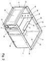
- the in the FIGS. 1 and 2 container shown consists essentially of a bottom plate 1, a rear wall 2, two side walls 3, 4 and a flap 5.
- the container walls 2, 3 and 4 are fixedly connected to the bottom plate 1 and at their points of contact.
- the flap 5 is pivotable about an axis 6 located in the region of the base plate 1.
- a removable cover plate 7 This has at the end of the flap 5 facing a substantially rectangularly downwardly angled plate member 8.
- the flap 5 has at its two narrow side surfaces depending on a substantially triangular tab 9.
- annular bearing pins 10 are formed on the outer side surfaces of the tabs.
- the bearing pins 10 are inserted into corresponding bearing bores 11 in the side walls 3, 4 and thus together form two pivot bearings with the already mentioned axis 6 for the flap 5.
- the lower part of the flap 5 is arc-shaped and forms a curvature 15, which ends with the lower edge 16 of the flap 5.
- the upper part of the flap 5 is angled inwards and forms together with rounded portions of an associated with the tabs 9 edge portion 18. In the open position forms from the curvature out obliquely upwardly extending flap 5 with the side flaps 9 and the now upwardly directed edge portion 18 a round limited, upwardly open recessed grip.
- a closing strip 19 is provided which largely closes the gap between the curvature 15 and the bottom plate 1 caused by the curvature 15 in the closed position of the flap 5.
- the upper part of the side walls 3, 4 and the rear wall 2 is bent to the outside, whereby on these walls 2, 3, 4 each an outwardly projecting flange 20 is formed.
- the 3 contiguous flanges 20 form the upper end of the container.
- an inner shoulder 22 is formed on the inside of the side walls 3, 4 depending on an inner shoulder 21 and on the rear wall 2, an inner shoulder 22 is formed.
- On the vertical wall parts of the shoulders 21 and thus on the inside of the two side walls 3, 4 are each two flat, elongated and vertically directed strips 23 are arranged, whose cross-sectional areas are semicircular.
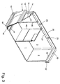
- the existing preferably made of a translucent material cover plate 7 is inserted from its grip trough-side end.
- the strips 23 prevent lifting of the cover plate upwards and at the same time a displacement of the box above it in the longitudinal direction.
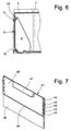
- the angled plate member 8 engages the upper portion of standing in its closed position Flap 5 ( Fig. 6 ), so that it is positively secured against unintentional pivoting in the open position.
- the front side of the box has in the front region of the shoulder on a survey that forms a positive securing the cover plate 7 against slipping in its longitudinal direction.
- a recess and a corresponding cam also form an additional, positive connection. This positive connection is intended to ensure that the elastic deformation required for closing and opening the flap can also occur when the cover plate 7 is inserted and possibly stacked boxes.
- this may be provided in the region of its handle trough-side free end with a recess for receiving an elastic support for the cover plate 7.
- each an outwardly projecting nose 30 is arranged, which corresponds with befindaji in the closed position flap 5 with a correspondingly formed recess 31 in the side walls 3, 4.
- the lugs 30 come under evasive deformation of the side walls 3, 4 and the flap 5 in the associated recess 31 a.
- the lugs 30 are pulled out of the recesses 31 again. Since in both cases elastic deformation forces are to be applied, the mutual association of the lugs 30 and the recesses 31 is a non-positively acting latching means for holding the flap 5.
- a narrow outwardly projecting flange 35 is formed in the region of the underside of the side walls 3, 4 in the region of the underside of the side walls 3, 4 is ever a narrow outwardly projecting flange 35 is formed.
- two recesses 36 are provided, which correspond in size, shape and mutual distance with the size, shape and the mutual distance of the strips 23.
- the width of the container to be measured from the outside of one flange 35 to the outside of the other flange 35 is slightly narrower than the mutual distance of the vertical wall parts of the shoulders 21. Therefore, a second container from above be placed on a first container, both on a closed by the cover plate 7, as well as on an open container.
- the second container is placed with its lower part between the vertical wall parts of the shoulders 21 on the cover plate 7, wherein the strips 23 engage in the corresponding recesses 36 of the flanges 35. If, however, the first container is open, the second container is placed with its lower part between the vertical wall portions of the shoulders 21 directly on the shoulders 21 and the shoulder 22, wherein in this case the strips 23 engage in corresponding recesses 36 of the flanges 35 ,
- two mutually spaced perpendicularly extending guide grooves 40 are formed, which serve to receive a dividing plate 41 dividing the interior of the container.
- the partition plate 41 is arranged vertically displaceable in the guide grooves 40. It has for this purpose a plurality of engaging in the guide grooves 40 and adapted to the width of guide elements 42 and a plurality of frictionally engaging on a boundary wall of the guide grooves 40 spring elements 43.
- the partition plate 41 is divided by a horizontally extending groove 44 into two height-separated sections 45, 46, wherein the guide elements 42 and spring elements 43 are arranged only on the upper portion 45.
- a handling element 47 is further arranged.
- the flap 5 is provided with a labeling field 50. Likewise, on the outside of the rear wall 2, a not shown in the drawing labeling field is provided. On the outside of the angled plate part 8 of the cover plate 7, a slot-shaped receiving pocket 51 is provided for a card-shaped information carrier, not shown.
- an L-shaped retaining strip 52 is formed.
- the container can be attached to a suitably designed for this carrier or frame.
- the container on the underside of the bottom plate 1 in the drawing, not shown on the sliding strips, which serve for the movement of the container on rolling rails of a rack or shelf.
- the small parts which are for example, screws or threaded nuts, are filled at the manufacturer in a container.
- the filling is done here preferably with removed cover plate 7 and located in the closed position flap 5 from above. If only one type of component is filled into the box and transported, a separator can be enclosed loosely. After filling the box, the cover plate 7 is placed on the shoulders 21, 22 of the container, wherein the strips 23 engage in the recesses 24
- the cover plate 7 is formed over the entire surface and is inserted from the grip trough-side end of the container in this, wherein the strips prevent lifting of the cover plate upwards and at the same time a displacement of the box above it in the longitudinal direction.
- the angled plate part 8 of the cover plate 7 engages over the upper edge portion 18 of the flap 5 and is located, as in Fig. 6 shown, close to the upper part of the vertically extending part of the flap. 5
- the side wall of the box has a survey in the front of the shoulder. This survey forms a positive position securing the cover plate 7 against slipping. Since the strips 23 prevent slipping of the cover plate 7 sure forms the cover plate 7 with its plate member 8 a positive lock that prevents accidental opening of the flap 5 safe.
- the Container also remains securely closed during transport from the manufacturer to the customer, even if the container is subject to shocks or jerky forces.
- one or more recesses may be incorporated in this - preferably in the region of its end face end, which serve to receive a respective elastic support body for the cover plate.
- the sealed container can then be placed in a warehouse. Since the container in the closed state has a cuboid shape and contains no bulky protruding components, the containers can be arranged close together or one behind the other lying or stacked and thus stacked as a space-saving storage units. This advantageous property can also already be used for the transport of the parts by forming space-saving shipping units from a plurality of containers stacked on one another.
- the appropriate container is removed from the warehouse and fed to the assembly site by z. B. is set to sloping rolling rails of a frame on which it slides by gravity to the actual assembly site. If the kanban (just-in-time) system is practiced in the assembly operation, the container removed from the store will encounter at least one container already present at the assembly site and abut against the rear side thereof. In this way, sufficient mounting material can be kept available without interruption.
- the flap 5 is pivoted downwards into its open position, wherein the lugs 30, overcoming an elastic deformation force the side walls 3, 4 and the flap 5 are pulled out of the recesses 31.
- the flap 5 forms a front and side closed recessed grip, in which the small parts in the container slip in and then are easily removed by hand.
- the entire interior of the container can be filled, it is advantageous to be able to regulate the flow rate of the small parts.
- This can be achieved in a simple manner by a separating plate 41 which can be inserted into one of the two pairs of guide grooves 40 and can assume different height positions with its lower edge in order to meter the flow cross-section and thus the back pressure.
- the container is sufficiently filled, can be dosed by the partition plate 41 which is inserted into one of the two pairs of guide grooves 40 and occupies different height positions with its lower edge, also the back pressure.
- the higher the partition plate is arranged the faster the small parts slip through the back pressure from back to front.
- the different height positions of the lower edge of the partition plate 41 can be realized by appropriately pulling up the partition plate 41 within the guide grooves 40.
- Another Dosier mecanickeit is to use from the outset a partition plate 41 with lesser height.
Landscapes
- Engineering & Computer Science (AREA)
- Mechanical Engineering (AREA)
- Details Of Rigid Or Semi-Rigid Containers (AREA)
- Rigid Containers With Two Or More Constituent Elements (AREA)
Claims (13)
- Récipient destiné à recevoir de petites pièces, présentant une plaque de fond (1), une paroi arrière (2) connectée à celle-ci et deux parois latérales (3, 4), la plaque de fond (1) et les parois de récipient (2, 3, 4) étant connectées fixement les unes aux autres, le récipient présentant en outre un volet (5) pouvant pivoter autour d'un axe horizontal (6) situé dans la région de la plaque de fond (1) et une plaque de recouvrement (7) servant à fermer le côté supérieur du récipient, la plaque de recouvrement (7), pour fixer le volet (5) par engagement par correspondance de formes, présentant une partie de plaque (8) coudée vers le bas qui recouvre la région supérieure du volet (5) se trouvant dans sa position de fermeture,
caractérisé en ce que
le volet (5) présente au niveau de ses faces latérales, pour former un creux de préhension fermé latéralement, à chaque fois une aile (9) saillant à angle droit, et
la position de pivotement du volet (5) dans sa position d'ouverture est fixée par une nervure de butée (17) réalisée au niveau de la plaque de fond (1), correspondant, à l'arête inférieure (16) du volet (5). - Récipient selon la revendication 1, caractérisé en ce que les ailes (9) du volet (5) sont reçues dans des évidements plats (12) au niveau du côté intérieur des parois latérales (3, 4) et en ce que les faces de limitation (14) étroites des évidements (12), s'étendant transversalement aux parois latérales (3, 4), lorsque le volet (5) se Lrouve dans la position de fermeture, correspondent aux surfaces de limitation étroites s'étendant transversalement (13) des ailes (9) et servent ainsi de butée pour le volet (5).
- Récipient selon la revendication 1 et 2, caractérisé en ce que la position de fermeture du volet (5), lorsque la plaque de recouvrement (7) est enlevée, peut être fixée par engagement par correspondance de formes par des moyens d'encliquetage élastiques (30, 31) disposés au niveau des ailes (9) et des parois latérales (3, 4).
- Récipient selon la revendication 1 à 3, caractérisé en ce que les parois latérales (3, 4) et la paroi arrière (2) présentant étroitement en dessous de leur arête supérieure, un épaulement (21 ; 22) pour recevoir la plaque de recouvrement (7) et pour recevoir la plaque de fond (1) d'un autre récipient posé, et en ce qu'au niveau du côté intérieur des parois latérales (3, 4) dans la région de l'épaulement (21) est disposée au moins une nervure (23) s'étendant perpendiculairement, allongée et plate, qui correspond à un évidement correspondant (24) dans la plaque de recouvrement (7) ainsi qu'à un évidement correspondant (36) au niveau du bord de la plaque de fond (1) d'un récipient posé.
- Récipient selon l'une quelconque des revendications 1 à 4, caractérisé en ce qu'au moins une plaque de séparation (41) peut être insérée dans le récipient.
- Récipient selon la revendication 5, caractérisé en ce que la plaque de séparation (41) est reçue et peut être déplacée en hauteur dans des rainures de guidage (40) des parois latérales (3, 4).
- Récipient selon les revendications 5 et 6, caractérisé en ce que la plaque de séparation (41) présente une plus faible hauteur que les parois latérales (3, 4).
- Récipient selon la revendication 7, caractérisé en ce que la plaque de séparation (41) est divisée en au moins deux portions (45, 46) séparées en hauteur et présente dans cette région de séparation une rainure (44) agissant en tans que zone destinée à la rupture.
- Récipient selon l'une quelconque des revendications 5 à 8, caractérisé en ce que la plaque de séparation (41) est supportée par des moyens de ressort (43) contre les parois latérales (3, 4).
- Récipient selon l'une quelconque des revendications 1 à 9, caractérisé en ce que le volet (5), la plaque de recouvrement (7) et/ou la plaque de séparation (41) se composent d'un matériau transparent.
- Récipient selon l'une quelconque des revendications 1 à 10, caractérisé en ce que le volet (5) et la paroi arrière (2) peuvent être munis d'inscriptions ou présentent des moyens de réception (51) pour des supports d'information.
- Récipient selon l'une quelconque des revendications 1 à 11, caractérisé en ce que des bandes plates sont disposées au niveau du côté inférieur de la plaque de fond, lesquelles servent à déplacer le récipient le long de glissières d'un châssis ou d'une étagère.
- Récipient selon l'une quelconque des revendications 1 à 11, caractérisé en ce que le récipient présente au niveau du côté extérieur de la paroi arrière (2) des moyens (52) pour accrocher le récipient.
Applications Claiming Priority (1)
| Application Number | Priority Date | Filing Date | Title |
|---|---|---|---|
| DE202013002265U DE202013002265U1 (de) | 2013-03-04 | 2013-03-04 | Behälter zur Aufnahme von Kleinteilen |
Publications (2)
| Publication Number | Publication Date |
|---|---|
| EP2774866A1 EP2774866A1 (fr) | 2014-09-10 |
| EP2774866B1 true EP2774866B1 (fr) | 2016-09-21 |
Family
ID=48794895
Family Applications (1)
| Application Number | Title | Priority Date | Filing Date |
|---|---|---|---|
| EP14000566.1A Active EP2774866B1 (fr) | 2013-03-04 | 2014-02-18 | Récipient destiné à recevoir des petites pièces |
Country Status (3)
| Country | Link |
|---|---|
| EP (1) | EP2774866B1 (fr) |
| DE (1) | DE202013002265U1 (fr) |
| ES (1) | ES2608796T3 (fr) |
Cited By (1)
| Publication number | Priority date | Publication date | Assignee | Title |
|---|---|---|---|---|
| US11884456B2 (en) | 2020-09-25 | 2024-01-30 | Techtronic Cordless Gp | Tool storage system |
Families Citing this family (5)
| Publication number | Priority date | Publication date | Assignee | Title |
|---|---|---|---|---|
| DE102015206606A1 (de) * | 2015-04-14 | 2016-10-20 | Adolf Würth GmbH & Co. KG | Sortimentbox und Anordnung mit wenigstens einer Sortimentbox und einer Halteleiste |
| CN109788675B (zh) * | 2017-11-13 | 2023-10-17 | 研祥智慧物联科技有限公司 | 操作机构和机箱 |
| CN112454311A (zh) * | 2019-04-22 | 2021-03-09 | 陶爱琴 | 一种野外生存专用工具箱 |
| NO20190842A1 (en) * | 2019-07-04 | 2020-04-08 | Stein Hofstad | A case for storing articles and carrying articles by hand |
| CN113855260B (zh) * | 2021-09-28 | 2023-08-15 | 北京中医药大学深圳医院(龙岗)(深圳市龙岗区中医院) | 防逆流新型利器盒 |
Family Cites Families (9)
| Publication number | Priority date | Publication date | Assignee | Title |
|---|---|---|---|---|
| US1445816A (en) * | 1921-09-08 | 1923-02-20 | Bailey Ellen | Butter container |
| US2715559A (en) * | 1952-02-08 | 1955-08-16 | Standard Pressed Steel Co | Factory storage bin |
| US3259269A (en) * | 1965-05-10 | 1966-07-05 | Shell Oil Co | Stackable bin container |
| DE7723429U1 (de) * | 1977-07-27 | 1977-11-10 | Adolf Wuerth Kg | Verpackung insbesondere fuer Kleineisenteile wie insbesondere Schrauben Muttern Unterlegscheiben o dgl |
| CH662540A5 (de) | 1983-12-09 | 1987-10-15 | Utz Ag Georg | Stapelbarer lager- und transportbehaelter aus kunststoff. |
| IT230396Y1 (it) * | 1993-07-26 | 1999-06-02 | Evoluzione Srl | Scatola impilabile ad apertura frontale |
| US7357271B2 (en) * | 2004-02-17 | 2008-04-15 | Tegrant Diversified Brands, Inc. | Insulated container with access door |
| DE202007001796U1 (de) | 2007-02-02 | 2007-04-05 | Rotho Kunststoff Ag | Kunststoffbehälter |
| DE102008034540A1 (de) * | 2008-07-21 | 2010-02-04 | Bb-Stanz- Und Umformtechnik Gmbh | Aufbewahrungskasten |
-
2013
- 2013-03-04 DE DE202013002265U patent/DE202013002265U1/de not_active Expired - Lifetime
-
2014
- 2014-02-18 ES ES14000566.1T patent/ES2608796T3/es active Active
- 2014-02-18 EP EP14000566.1A patent/EP2774866B1/fr active Active
Cited By (1)
| Publication number | Priority date | Publication date | Assignee | Title |
|---|---|---|---|---|
| US11884456B2 (en) | 2020-09-25 | 2024-01-30 | Techtronic Cordless Gp | Tool storage system |
Also Published As
| Publication number | Publication date |
|---|---|
| EP2774866A1 (fr) | 2014-09-10 |
| DE202013002265U1 (de) | 2013-06-13 |
| ES2608796T3 (es) | 2017-04-17 |
Similar Documents
| Publication | Publication Date | Title |
|---|---|---|
| EP2774866B1 (fr) | Récipient destiné à recevoir des petites pièces | |
| DE102017128493B3 (de) | Stapelbarer Systembehälter und Transportsystem | |
| DE202011000908U1 (de) | Anordnung eines vorhängeschlossartigen Behälters | |
| EP2147867B1 (fr) | Boîtier de stockage | |
| DE20314301U1 (de) | Stapelbarer Werkzeugkoffer | |
| EP1533244B1 (fr) | Réceptacle avec un couvercle monté de manière pivotante | |
| DE202016000950U1 (de) | Transportvorrichtung | |
| EP0608822A2 (fr) | Cassette pour disque compact avec moyen de fixation | |
| EP3658339A1 (fr) | Boîte de rangement et rayonnage | |
| CH645584A5 (de) | Stapelbarer transport- und lagersichtkasten aus kunststoff. | |
| DE3110025A1 (de) | "aufbewahrungsanordnung" | |
| EP1982926B1 (fr) | Récipients de stockage et de transport | |
| DE2358176A1 (de) | Behaelter mit schiebedeckel | |
| DE3724828C1 (de) | Sichtlagerkasten | |
| EP3587294A1 (fr) | Récipient empilable pourvu de mécanisme de raccordement | |
| DE1654542A1 (de) | Aufbewahrungsvorrichtung mit schraeggestellten Regalboeden | |
| DE2041066B2 (de) | Kiste für Flaschen | |
| DE102013224880A1 (de) | Kältegerät und Fachboden dafür | |
| EP0236514B1 (fr) | Caisse de transport et de stockage en matière plastique | |
| EP3663230A1 (fr) | Conteneur de transport | |
| DE102013006364B4 (de) | Ordnungssystem mit Verpackungsschachteln | |
| DE102009010986B4 (de) | Vorrichtung zur Sicherung von Gitterboxklappen | |
| WO1996025335A2 (fr) | Systeme de coffrets pour lettres | |
| EP3067160B1 (fr) | Dispositif de stockage pour outils | |
| DE4325185C2 (de) | Vorrichtung zum Verriegeln eines auf dem Umfangsrand einer Tonne, insbesondere Mülltonne, aufliegenden Deckels |
Legal Events
| Date | Code | Title | Description |
|---|---|---|---|
| PUAI | Public reference made under article 153(3) epc to a published international application that has entered the european phase |
Free format text: ORIGINAL CODE: 0009012 |
|
| 17P | Request for examination filed |
Effective date: 20140218 |
|
| AK | Designated contracting states |
Kind code of ref document: A1 Designated state(s): AL AT BE BG CH CY CZ DE DK EE ES FI FR GB GR HR HU IE IS IT LI LT LU LV MC MK MT NL NO PL PT RO RS SE SI SK SM TR |
|
| AX | Request for extension of the european patent |
Extension state: BA ME |
|
| R17P | Request for examination filed (corrected) |
Effective date: 20150310 |
|
| RBV | Designated contracting states (corrected) |
Designated state(s): AL AT BE BG CH CY CZ DE DK EE ES FI FR GB GR HR HU IE IS IT LI LT LU LV MC MK MT NL NO PL PT RO RS SE SI SK SM TR |
|
| RIC1 | Information provided on ipc code assigned before grant |
Ipc: B65D 21/02 20060101ALI20160217BHEP Ipc: B65D 43/12 20060101ALI20160217BHEP Ipc: B65D 43/02 20060101ALI20160217BHEP Ipc: B65D 25/06 20060101ALI20160217BHEP Ipc: B65D 25/00 20060101AFI20160217BHEP Ipc: B25H 3/02 20060101ALI20160217BHEP |
|
| GRAP | Despatch of communication of intention to grant a patent |
Free format text: ORIGINAL CODE: EPIDOSNIGR1 |
|
| INTG | Intention to grant announced |
Effective date: 20160330 |
|
| GRAS | Grant fee paid |
Free format text: ORIGINAL CODE: EPIDOSNIGR3 |
|
| GRAA | (expected) grant |
Free format text: ORIGINAL CODE: 0009210 |
|
| AK | Designated contracting states |
Kind code of ref document: B1 Designated state(s): AL AT BE BG CH CY CZ DE DK EE ES FI FR GB GR HR HU IE IS IT LI LT LU LV MC MK MT NL NO PL PT RO RS SE SI SK SM TR |
|
| REG | Reference to a national code |
Ref country code: GB Ref legal event code: FG4D Free format text: NOT ENGLISH |
|
| REG | Reference to a national code |
Ref country code: CH Ref legal event code: EP |
|
| REG | Reference to a national code |
Ref country code: AT Ref legal event code: REF Ref document number: 830829 Country of ref document: AT Kind code of ref document: T Effective date: 20161015 |
|
| REG | Reference to a national code |
Ref country code: IE Ref legal event code: FG4D Free format text: LANGUAGE OF EP DOCUMENT: GERMAN |
|
| REG | Reference to a national code |
Ref country code: DE Ref legal event code: R096 Ref document number: 502014001464 Country of ref document: DE |
|
| REG | Reference to a national code |
Ref country code: LT Ref legal event code: MG4D Ref country code: NL Ref legal event code: MP Effective date: 20160921 |
|
| PG25 | Lapsed in a contracting state [announced via postgrant information from national office to epo] |
Ref country code: RS Free format text: LAPSE BECAUSE OF FAILURE TO SUBMIT A TRANSLATION OF THE DESCRIPTION OR TO PAY THE FEE WITHIN THE PRESCRIBED TIME-LIMIT Effective date: 20160921 Ref country code: FI Free format text: LAPSE BECAUSE OF FAILURE TO SUBMIT A TRANSLATION OF THE DESCRIPTION OR TO PAY THE FEE WITHIN THE PRESCRIBED TIME-LIMIT Effective date: 20160921 Ref country code: LT Free format text: LAPSE BECAUSE OF FAILURE TO SUBMIT A TRANSLATION OF THE DESCRIPTION OR TO PAY THE FEE WITHIN THE PRESCRIBED TIME-LIMIT Effective date: 20160921 Ref country code: NO Free format text: LAPSE BECAUSE OF FAILURE TO SUBMIT A TRANSLATION OF THE DESCRIPTION OR TO PAY THE FEE WITHIN THE PRESCRIBED TIME-LIMIT Effective date: 20161221 |
|
| PG25 | Lapsed in a contracting state [announced via postgrant information from national office to epo] |
Ref country code: SE Free format text: LAPSE BECAUSE OF FAILURE TO SUBMIT A TRANSLATION OF THE DESCRIPTION OR TO PAY THE FEE WITHIN THE PRESCRIBED TIME-LIMIT Effective date: 20160921 Ref country code: NL Free format text: LAPSE BECAUSE OF FAILURE TO SUBMIT A TRANSLATION OF THE DESCRIPTION OR TO PAY THE FEE WITHIN THE PRESCRIBED TIME-LIMIT Effective date: 20160921 Ref country code: GR Free format text: LAPSE BECAUSE OF FAILURE TO SUBMIT A TRANSLATION OF THE DESCRIPTION OR TO PAY THE FEE WITHIN THE PRESCRIBED TIME-LIMIT Effective date: 20161222 Ref country code: LV Free format text: LAPSE BECAUSE OF FAILURE TO SUBMIT A TRANSLATION OF THE DESCRIPTION OR TO PAY THE FEE WITHIN THE PRESCRIBED TIME-LIMIT Effective date: 20160921 |
|
| REG | Reference to a national code |
Ref country code: CH Ref legal event code: NV Representative=s name: PATENTANWAELTE KLEIN AND KLEIN, CH |
|
| REG | Reference to a national code |
Ref country code: ES Ref legal event code: FG2A Ref document number: 2608796 Country of ref document: ES Kind code of ref document: T3 Effective date: 20170417 |
|
| PG25 | Lapsed in a contracting state [announced via postgrant information from national office to epo] |
Ref country code: RO Free format text: LAPSE BECAUSE OF FAILURE TO SUBMIT A TRANSLATION OF THE DESCRIPTION OR TO PAY THE FEE WITHIN THE PRESCRIBED TIME-LIMIT Effective date: 20160921 Ref country code: EE Free format text: LAPSE BECAUSE OF FAILURE TO SUBMIT A TRANSLATION OF THE DESCRIPTION OR TO PAY THE FEE WITHIN THE PRESCRIBED TIME-LIMIT Effective date: 20160921 |
|
| PG25 | Lapsed in a contracting state [announced via postgrant information from national office to epo] |
Ref country code: PL Free format text: LAPSE BECAUSE OF FAILURE TO SUBMIT A TRANSLATION OF THE DESCRIPTION OR TO PAY THE FEE WITHIN THE PRESCRIBED TIME-LIMIT Effective date: 20160921 Ref country code: SM Free format text: LAPSE BECAUSE OF FAILURE TO SUBMIT A TRANSLATION OF THE DESCRIPTION OR TO PAY THE FEE WITHIN THE PRESCRIBED TIME-LIMIT Effective date: 20160921 Ref country code: CZ Free format text: LAPSE BECAUSE OF FAILURE TO SUBMIT A TRANSLATION OF THE DESCRIPTION OR TO PAY THE FEE WITHIN THE PRESCRIBED TIME-LIMIT Effective date: 20160921 Ref country code: PT Free format text: LAPSE BECAUSE OF FAILURE TO SUBMIT A TRANSLATION OF THE DESCRIPTION OR TO PAY THE FEE WITHIN THE PRESCRIBED TIME-LIMIT Effective date: 20170123 Ref country code: IS Free format text: LAPSE BECAUSE OF FAILURE TO SUBMIT A TRANSLATION OF THE DESCRIPTION OR TO PAY THE FEE WITHIN THE PRESCRIBED TIME-LIMIT Effective date: 20170121 Ref country code: BG Free format text: LAPSE BECAUSE OF FAILURE TO SUBMIT A TRANSLATION OF THE DESCRIPTION OR TO PAY THE FEE WITHIN THE PRESCRIBED TIME-LIMIT Effective date: 20161221 Ref country code: BE Free format text: LAPSE BECAUSE OF NON-PAYMENT OF DUE FEES Effective date: 20170228 Ref country code: SK Free format text: LAPSE BECAUSE OF FAILURE TO SUBMIT A TRANSLATION OF THE DESCRIPTION OR TO PAY THE FEE WITHIN THE PRESCRIBED TIME-LIMIT Effective date: 20160921 |
|
| REG | Reference to a national code |
Ref country code: DE Ref legal event code: R097 Ref document number: 502014001464 Country of ref document: DE |
|
| PLBE | No opposition filed within time limit |
Free format text: ORIGINAL CODE: 0009261 |
|
| STAA | Information on the status of an ep patent application or granted ep patent |
Free format text: STATUS: NO OPPOSITION FILED WITHIN TIME LIMIT |
|
| PG25 | Lapsed in a contracting state [announced via postgrant information from national office to epo] |
Ref country code: DK Free format text: LAPSE BECAUSE OF FAILURE TO SUBMIT A TRANSLATION OF THE DESCRIPTION OR TO PAY THE FEE WITHIN THE PRESCRIBED TIME-LIMIT Effective date: 20160921 |
|
| 26N | No opposition filed |
Effective date: 20170622 |
|
| REG | Reference to a national code |
Ref country code: FR Ref legal event code: PLFP Year of fee payment: 4 |
|
| PG25 | Lapsed in a contracting state [announced via postgrant information from national office to epo] |
Ref country code: MC Free format text: LAPSE BECAUSE OF FAILURE TO SUBMIT A TRANSLATION OF THE DESCRIPTION OR TO PAY THE FEE WITHIN THE PRESCRIBED TIME-LIMIT Effective date: 20160921 |
|
| PG25 | Lapsed in a contracting state [announced via postgrant information from national office to epo] |
Ref country code: SI Free format text: LAPSE BECAUSE OF FAILURE TO SUBMIT A TRANSLATION OF THE DESCRIPTION OR TO PAY THE FEE WITHIN THE PRESCRIBED TIME-LIMIT Effective date: 20160921 |
|
| PG25 | Lapsed in a contracting state [announced via postgrant information from national office to epo] |
Ref country code: LU Free format text: LAPSE BECAUSE OF NON-PAYMENT OF DUE FEES Effective date: 20170218 |
|
| REG | Reference to a national code |
Ref country code: BE Ref legal event code: MM Effective date: 20170228 |
|
| REG | Reference to a national code |
Ref country code: FR Ref legal event code: PLFP Year of fee payment: 5 |
|
| PG25 | Lapsed in a contracting state [announced via postgrant information from national office to epo] |
Ref country code: MT Free format text: LAPSE BECAUSE OF FAILURE TO SUBMIT A TRANSLATION OF THE DESCRIPTION OR TO PAY THE FEE WITHIN THE PRESCRIBED TIME-LIMIT Effective date: 20160921 |
|
| PG25 | Lapsed in a contracting state [announced via postgrant information from national office to epo] |
Ref country code: AL Free format text: LAPSE BECAUSE OF FAILURE TO SUBMIT A TRANSLATION OF THE DESCRIPTION OR TO PAY THE FEE WITHIN THE PRESCRIBED TIME-LIMIT Effective date: 20160921 |
|
| REG | Reference to a national code |
Ref country code: IE Ref legal event code: MM4A |
|
| PG25 | Lapsed in a contracting state [announced via postgrant information from national office to epo] |
Ref country code: IE Free format text: LAPSE BECAUSE OF NON-PAYMENT OF DUE FEES Effective date: 20170218 |
|
| PG25 | Lapsed in a contracting state [announced via postgrant information from national office to epo] |
Ref country code: HU Free format text: LAPSE BECAUSE OF FAILURE TO SUBMIT A TRANSLATION OF THE DESCRIPTION OR TO PAY THE FEE WITHIN THE PRESCRIBED TIME-LIMIT; INVALID AB INITIO Effective date: 20140218 |
|
| PG25 | Lapsed in a contracting state [announced via postgrant information from national office to epo] |
Ref country code: CY Free format text: LAPSE BECAUSE OF NON-PAYMENT OF DUE FEES Effective date: 20160921 |
|
| PG25 | Lapsed in a contracting state [announced via postgrant information from national office to epo] |
Ref country code: MK Free format text: LAPSE BECAUSE OF FAILURE TO SUBMIT A TRANSLATION OF THE DESCRIPTION OR TO PAY THE FEE WITHIN THE PRESCRIBED TIME-LIMIT Effective date: 20160921 |
|
| PG25 | Lapsed in a contracting state [announced via postgrant information from national office to epo] |
Ref country code: TR Free format text: LAPSE BECAUSE OF FAILURE TO SUBMIT A TRANSLATION OF THE DESCRIPTION OR TO PAY THE FEE WITHIN THE PRESCRIBED TIME-LIMIT Effective date: 20160921 |
|
| PG25 | Lapsed in a contracting state [announced via postgrant information from national office to epo] |
Ref country code: HR Free format text: LAPSE BECAUSE OF FAILURE TO SUBMIT A TRANSLATION OF THE DESCRIPTION OR TO PAY THE FEE WITHIN THE PRESCRIBED TIME-LIMIT Effective date: 20160921 |
|
| PGFP | Annual fee paid to national office [announced via postgrant information from national office to epo] |
Ref country code: IT Payment date: 20230830 Year of fee payment: 10 Ref country code: GB Payment date: 20230830 Year of fee payment: 10 Ref country code: ES Payment date: 20230825 Year of fee payment: 10 Ref country code: CH Payment date: 20230828 Year of fee payment: 10 Ref country code: AT Payment date: 20230831 Year of fee payment: 10 |
|
| PGFP | Annual fee paid to national office [announced via postgrant information from national office to epo] |
Ref country code: FR Payment date: 20230830 Year of fee payment: 10 Ref country code: DE Payment date: 20230830 Year of fee payment: 10 |