EP2774571B1 - Dynamoelektrischer Wandler und medizinische, insbesondere dentale, Vorrichtung mit einem dynamoelektrischen Wandler - Google Patents
Dynamoelektrischer Wandler und medizinische, insbesondere dentale, Vorrichtung mit einem dynamoelektrischen Wandler Download PDFInfo
- Publication number
- EP2774571B1 EP2774571B1 EP13158142.3A EP13158142A EP2774571B1 EP 2774571 B1 EP2774571 B1 EP 2774571B1 EP 13158142 A EP13158142 A EP 13158142A EP 2774571 B1 EP2774571 B1 EP 2774571B1
- Authority
- EP
- European Patent Office
- Prior art keywords
- sleeve
- fluid
- medical
- impeller
- rotor
- Prior art date
- Legal status (The legal status is an assumption and is not a legal conclusion. Google has not performed a legal analysis and makes no representation as to the accuracy of the status listed.)
- Active
Links
Images


Classifications
-
- F—MECHANICAL ENGINEERING; LIGHTING; HEATING; WEAPONS; BLASTING
- F03—MACHINES OR ENGINES FOR LIQUIDS; WIND, SPRING, OR WEIGHT MOTORS; PRODUCING MECHANICAL POWER OR A REACTIVE PROPULSIVE THRUST, NOT OTHERWISE PROVIDED FOR
- F03B—MACHINES OR ENGINES FOR LIQUIDS
- F03B13/00—Adaptations of machines or engines for special use; Combinations of machines or engines with driving or driven apparatus; Power stations or aggregates
- F03B13/04—Adaptations for use in dentistry for driving tools or the like having relatively small outer diameter, e.g. pipe cleaning tools
-
- A—HUMAN NECESSITIES
- A61—MEDICAL OR VETERINARY SCIENCE; HYGIENE
- A61B—DIAGNOSIS; SURGERY; IDENTIFICATION
- A61B17/00—Surgical instruments, devices or methods
-
- A—HUMAN NECESSITIES
- A61—MEDICAL OR VETERINARY SCIENCE; HYGIENE
- A61C—DENTISTRY; APPARATUS OR METHODS FOR ORAL OR DENTAL HYGIENE
- A61C1/00—Dental machines for boring or cutting ; General features of dental machines or apparatus, e.g. hand-piece design
- A61C1/02—Dental machines for boring or cutting ; General features of dental machines or apparatus, e.g. hand-piece design characterised by the drive of the dental tools
- A61C1/05—Dental machines for boring or cutting ; General features of dental machines or apparatus, e.g. hand-piece design characterised by the drive of the dental tools with turbine drive
- A61C1/052—Ducts for supplying driving or cooling fluid, e.g. air, water
-
- H—ELECTRICITY
- H02—GENERATION; CONVERSION OR DISTRIBUTION OF ELECTRIC POWER
- H02K—DYNAMO-ELECTRIC MACHINES
- H02K5/00—Casings; Enclosures; Supports
- H02K5/04—Casings or enclosures characterised by the shape, form or construction thereof
- H02K5/12—Casings or enclosures characterised by the shape, form or construction thereof specially adapted for operating in liquid or gas
- H02K5/128—Casings or enclosures characterised by the shape, form or construction thereof specially adapted for operating in liquid or gas using air-gap sleeves or air-gap discs
-
- H—ELECTRICITY
- H02—GENERATION; CONVERSION OR DISTRIBUTION OF ELECTRIC POWER
- H02K—DYNAMO-ELECTRIC MACHINES
- H02K7/00—Arrangements for handling mechanical energy structurally associated with dynamo-electric machines, e.g. structural association with mechanical driving motors or auxiliary dynamo-electric machines
- H02K7/18—Structural association of electric generators with mechanical driving motors, e.g. with turbines
- H02K7/1807—Rotary generators
- H02K7/1823—Rotary generators structurally associated with turbines or similar engines
-
- A—HUMAN NECESSITIES
- A61—MEDICAL OR VETERINARY SCIENCE; HYGIENE
- A61B—DIAGNOSIS; SURGERY; IDENTIFICATION
- A61B17/00—Surgical instruments, devices or methods
- A61B2017/00535—Surgical instruments, devices or methods pneumatically or hydraulically operated
- A61B2017/00553—Surgical instruments, devices or methods pneumatically or hydraulically operated using a turbine
-
- H—ELECTRICITY
- H02—GENERATION; CONVERSION OR DISTRIBUTION OF ELECTRIC POWER
- H02K—DYNAMO-ELECTRIC MACHINES
- H02K21/00—Synchronous motors having permanent magnets; Synchronous generators having permanent magnets
- H02K21/12—Synchronous motors having permanent magnets; Synchronous generators having permanent magnets with stationary armatures and rotating magnets
-
- H—ELECTRICITY
- H02—GENERATION; CONVERSION OR DISTRIBUTION OF ELECTRIC POWER
- H02K—DYNAMO-ELECTRIC MACHINES
- H02K7/00—Arrangements for handling mechanical energy structurally associated with dynamo-electric machines, e.g. structural association with mechanical driving motors or auxiliary dynamo-electric machines
- H02K7/14—Structural association with mechanical loads, e.g. with hand-held machine tools or fans
- H02K7/145—Hand-held machine tool
Definitions
- the present invention relates to a fluid-operated, dynamoelectric converter for generating electrical energy and a medical, in particular dental, device with a fluid-operated, dynamoelectric converter.
- the patent application US 2008/261172 A1 discloses a fluid operated, dynamoelectric transducer for generating electrical energy and a medical, in particular dental, device in the form of a handpiece or a coupling element with a fluid operated, dynamoelectric transducer.
- a fluid-operated, dynamoelectric transducer in a handpiece or in a coupling element makes it possible to provide an electrical consumer in the handpiece or in the coupling element, in particular a lighting device, with electrical energy of the dynamoelectric converter without the handpiece or the coupling element with a electrical energy source is connected.
- Such handpieces or coupling elements with fluid operated dynamoelectric transducers produced and sold by the Applicant for several years are greatly appreciated by the users.
- the documents FR253891 and US2012 / 0115101 also disclose fluid operated dynamoelectric transducers.
- the present invention has for its object a fluid-driven, dynamoelectric converter for a medical, especially dental, device to develop further.
- it is intended to simplify the construction of the fluid-operated, dynamoelectric converter, reduce its dimensions and facilitate integration or installation in the medical, in particular dental, device, without causing losses in the electrical performance of the dynamoelectric converter.
- the fluid-operated dynamoelectric converter comprises: a rotor having a rotatable by a fluid impeller and at least one magnetic element with the impeller is connected, so that the magnetic element by the rotatable impeller also set in rotation is a stator having an electrical winding which cooperates with the rotatable magnetic element such that in the electrical winding electrical energy is generated, a sleeve which surrounds at least parts of the rotor and / or the stator, and one integral with the sleeve the fluid line formed of the dynamoelectric converter, which projects beyond the connection end of the medical, in particular dental, device at least with its end facing away from the dynamoelectric converter end.
- a fluid operated dynamoelectric transducer comprising: a rotor having a fluidizable rotatable impeller having a plurality of blades, at least one magnet member connected to the impeller such that the magnet member is rotatable by the rotatable impeller is also set in rotation, and with a rotor sleeve, in which the at least one magnetic element of the rotor is arranged, and a stator with an electrical winding, which cooperates with the rotatable magnetic element such that electrical energy can be generated in the electrical winding, wherein the impeller, in particular the blades of the impeller, is integrally formed with the rotor sleeve / and in particular on an outer side of the rotor sleeve and / or arranged at one end of the rotor sleeve / are.
- a fluid operated dynamoelectric transducer comprising: a rotor having a fluidizable rotatable impeller and at least one magnet member connected to the impeller such that the magnet member is also rotated by the rotatable impeller Rotation is displaceable, and a stator with an electrical winding, which cooperates with the rotatable magnetic element such that in the electrical winding electrical energy is generated, and with a magnetic return element for concentrating and directing the magnetic field lines of the at least one magnetic element through the electrical winding.
- the magnetic return element comprises or is formed as a one-piece sleeve-shaped magnetic yoke surrounding the rotor and the electrical winding and comprising a magnetically conductive material.
- the one-piece design of components causes a simpler integration of the fluid-operated, dynamoelectric transducer in the medical, in particular dental device and / or a smaller space consumption in the interior of the medical, in particular dental device. Due to the smaller space consumption, it is thus also possible in an advantageous manner, other components of the medical, in particular dental device, for example, a fluid line or a light guide on passing the generator over and / or placing it next to the generator. In particular, by combining several of these one-piece training a significant reduction of the generator could be achieved.
- the integrally formed with the sleeve of the generator fluid line which protrudes at least with its remote from the generator end over the terminal end of the medical, especially dental, device is advantageously a simple installation in the medical, especially dental, device or a simple replacement of the generator possible.
- the generator with the fluid line formed integrally with the sleeve can be inserted by pushing or plugging into a receptacle of the medical, in particular dental, device.
- the receptacle is arranged or dimensioned such that, when the dynamoelectric transducer is accommodated in the receptacle and assumes its operating position, the fluid conduit formed integrally with the sleeve of the dynamoelectric transducer at least with its end facing away from the dynamoelectric converter via the terminal end of the medical, in particular dental, device protrudes.
- a coupling device for connection to a fluid source and / or a coupling element for connection to a fluid source in particular a coupling element which directly engages with a fluid source
- Counter-coupling element for example, with a coupling portion of a fluid line, detachably coupled, in particular fauxsteckbar is.
- the electrical winding of the stator has a printed conductor track.
- the electrical winding of the stator has a flexible or flexible or spirally rollable carrier element, in particular a flexible or spirally rollable board.
- the support member is formed flat or band-shaped with two substantially opposite sides.
- the electrical conductor of the electrical winding for example a copper-containing electrical conductor, is provided on both substantially opposite sides of the carrier element.
- a through-contacting of the carrier element is provided for connecting the electrical conductor on both sides of the carrier element.
- a further simplification of the structure and also a reduction of the generator was preferably created by the fact that for the guidance of the impeller driving fluid substantially only the sleeve, which surrounds at least parts of the rotor and / or stator, and / or the outer sleeve and / or the outer sleeve, which has the one-piece, sleeve-shaped magnetic return element is provided.
- the impeller driving fluid substantially only the sleeve, which surrounds at least parts of the rotor and / or stator, and / or the outer sleeve and / or the outer sleeve, which has the one-piece, sleeve-shaped magnetic return element is provided.
- At least one of the following elements is provided on the sleeve or outer sleeve, for example: a bore, which is connected in particular to the fluid line formed integrally with the sleeve or outer sleeve; a first outlet opening provided on the outside of the sleeve or outer sleeve and in particular connected to the bore and / or with the fluid line formed integrally with the sleeve or outer sleeve, so that the fluid can be conducted to the outside of the sleeve or outer sleeve; wherein the at least one on the outside of the sleeve or outer sleeve, preferably annular or circular arc, groove is connected to the bore and / or with the first outlet opening; at least one inlet opening provided on the outside of the sleeve or outer sleeve, so that the fluid from the outside of the sleeve or outer sleeve, in particular of the groove, in the interior of the slee
- the generator and / or the medical, in particular dental, device are designed such that the fluid after the passage of the impeller, in particular for cooling, along the outside of the sleeve or outer sleeve of the generator and / or in a subsequent to the generator or this surrounding recess is conductive and / or derivable in particular in a subsequent to the generator fluid line.
- a further embodiment is / are in the interior of the at least one magnetic element receiving rotor sleeve and / or inside the impeller, in particular radially inside the blades of the impeller, a bearing and / or a bearing, in particular a rolling or ball bearing, for rotatable mounting the rotor sleeve and / or the impeller arranged.
- This causes a, in particular axial shortening and an even more compact construction of the generator.
- a rotor shaft accommodated in the interior of the rotor sleeve and / or in the interior of the rotor wheel, in particular radially inside the blades of the rotor wheel, is also provided for the rotatable mounting of the rotor sleeve.
- the rotor sleeve formed integrally with the impeller has a first portion, in which at least a part of the at least one magnetic element is accommodated, and a second portion, on which the blades of the impeller are provided, wherein the outer diameter of the first portion is smaller is as the outer diameter of the second portion, so that a recess is formed on the first portion.
- at least part of the electrical winding and / or at least part of a carrier or bearing element for the electrical winding and / or an air gap of the generator is provided in or at the recess.
- the compactness of the generator is increased and its size, in particular its diameter, reduced.
- the medical, in particular dental, device in which the fluid-operated, dynamoelectric converter is provided comprises, for example, a straight, curved or pistol-shaped handpiece or handle element, an adapter or a coupling device.
- the handpiece or handle element, the adapter or the coupling device have, for example, an electrical consumer, preferably a lighting device, in particular at least one optical semiconductor element which can be supplied and / or operated with the electrical energy generated by the generator.
- the generator and the electrical load are separable from each other, in particular they are not arranged in the same component.
- the handpiece or handle member, the adapter or the coupling device comprise electrical contacts and / or electrical conductors which connect the generator to the electrical load.
- the handpiece or handle element comprises at least one fluid-operated drive element for moving a tool that can be connected to the handpiece or handle element.
- the adapter or the coupling device comprise a connection end detachably connectable to a fluid source and a connecting end spaced therefrom for detachable connection to a medical, in particular dental, instrument, for example a handle element.
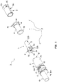
- the FIG. 1 shows as main elements of the fluid-operated, dynamoelectric converter 3, a rotor 4 and a stator 7.
- the rotor 4 comprises a rotatable by a fluid in an impeller 5 and at least one magnetic element 6.
- the magnetic element 6 is connected to the impeller 5, so that the magnetic element 6 is also set in rotation by the rotatable impeller 5 in rotation.
- the stator 7 has an electrical winding 8 which cooperates with the magnetic element 6 which can be set in rotation such that electrical energy can be generated in the electrical winding 8.
- the rotor 4 has a longitudinal or rotational axis 35 about which the rotor 4 is rotatably arranged.
- the magnetic element 6 of the rotor 4 is preferably designed as a permanent magnet.
- the magnetic element 6 is designed as a two-pole or multi-pole magnetic element.
- the magnetic element 6 is preferably cylindrically shaped.
- the magnetic element 6 is preferably arranged or received in a rotor sleeve 22 and / or fixed therein, in particular glued or pressed.
- the rotor sleeve 22 is preferably hollow and in particular has an inner space 36.
- at least the magnetic element 6 is received in the inner space 36.
- one end of the rotor sleeve 22 is closed by an end wall 39.
- the fluid-driven impeller 5 of the rotor 4 preferably has a plurality of blades 5A.
- the impeller 5 is preferably arranged substantially concentrically with the magnetic element 6 and / or with the rotor sleeve 22.
- the impeller 5, in particular the blades 5A, is / are preferably arranged radially around the axis of rotation 35.
- the Impeller 5 is preferably hollow and / or has a cavity 38.
- the impeller 5, in particular the cavity 38, for receiving at least one component of the generator 3 is formed, for example, for receiving a bearing 24 for rotatably supporting the impeller 5 and / or for receiving a shaft or rotor shaft 28 for rotatably supporting the impeller 5.
- a bearing point 23 is provided, in particular for the bearing 24 for rotatably supporting the impeller 5.
- the bearing 24 comprises a rolling or ball bearing.
- the blades 5A of the impeller 5 are arranged radially around the cavity 38.
- the cavity 38 has an inner wall from which the blades 5A extend radially outward.
- annular flange 32 is provided on at least one end of the impeller 5, which rotates the impeller 5 on its outer periphery.
- the blades 5A of the impeller 5 connect to the annular flange 32 or are connected to the annular flange 32.
- the annular flange 32 forms an axial end of the impeller 5.
- the annular flange 32 is provided to direct the fluid which drives the impeller 5 or with which the impeller 5 can be acted upon.
- the annular flange 32 is formed integrally with the impeller 5 and / or the blades 5A.
- the blades 5A of the impeller 5 are arranged on an outer side of the rotor sleeve 22 and / or at one end of the rotor sleeve 22.
- the impeller 5, in particular the blades 5A, and the rotor sleeve 22 are thus formed as a single, common component.
- the interior 36 of the rotor sleeve 22 and the cavity 38 of the impeller are interconnected or form a common interior.
- the inner space 36 of the rotor sleeve 22 or the common interior formed from the inner space 36 and the cavity 38 for receiving a bearing 24 for rotatably supporting the impeller 5 and the rotor sleeve 22 with the magnetic element 6 and / or for receiving a rotor shaft 28 for rotatable mounting of the impeller 5 and the rotor sleeve 22 is formed with the magnetic element 6.
- a bearing 23 is provided in the inner space 36 or the common interior, in particular for the bearing 24.
- the bearing 24 comprises a rolling or ball bearing.
- the blades 5A of the impeller 5 are arranged radially around the inner space 36 or the common inner space.
- the common interior space has an inner wall from which the blades 5A extend radially outward.
- an opening 37 is provided on the rotor sleeve 22, in particular on one end of the rotor sleeve 22, or on the impeller 5, through which at least the magnetic element 6, optionally further component of the generator 3, in particular the bearing 24 and / or the shaft 28, in the rotor sleeve 22 and / or in the impeller 5 are inserted.
- the opening 37 is arranged at the end wall 39 opposite the end of the rotor sleeve 22 and / or the impeller 5.
- the rotor sleeve 22 is formed with the integrally formed impeller 5 as, in particular pot-shaped, sleeve with a bore 36, 38, in which the magnetic element 6 and in particular the bearing 24 and / or the shaft 28 are arranged.
- the rotor pin 29 is arranged at one end of the rotor sleeve 22, in particular on the end wall 39 of the rotor sleeve 22.
- a bearing 40 in particular a rolling or ball bearing, for rotatably supporting the rotor sleeve 22 and / or the impeller 5 provided.
- the rotor sleeve 22 has a first portion 22A, in which at least a part of the at least one magnetic element 6 is accommodated, and a second portion 22B, on which the impeller 5 or the blades 5A of the impeller 5 is / are provided.
- the outer diameter of the first portion 22A is less than the outer diameter of the second portion 22B.
- a return 30 is formed on the first portion 22A.
- the side wall or the axial boundary of the recess 30 is in particular formed by the blades 5A of the impeller 5, in particular by their lateral ends or free side ends.
- the outer diameter of the impeller 5 or the blades 5A, at least the outer or radial ends of the blades 5A is larger than the outer diameter of the first portion 22A.
- At least part of the electrical winding 8 and / or at least part of a bearing or support element 21 for the electrical winding 8 and / or an air gap 31 of the dynamoelectric converter 3 is provided in or at the recess 30.
- the electrical winding 8 and / or at least part of the bearing or support element 21 and / or the air gap 31 is / are thus preferably arranged axially on the impeller 5, in particular on the blades 5A of the impeller 5, subsequently.
- the Electrical winding 8 and / or at least a portion of the bearing or support member 21 and / or the air gap 31 preferably extend over substantially the entire first portion 22A.
- the electrical winding 8 of the stator 7 is preferably arranged at least around a part of the rotor 4, in particular around the magnetic element 6 and / or the rotor sleeve 22, preferably its section 22A.
- the electrical winding 8 comprises, for example, at least one wound coil winding.
- the electrical winding 8 comprises at least one printed conductor 8A.
- the electrical winding 8 has a flexible or flexible or spirally rollable carrier element, in particular a flexible or spirally rollable board on which the printed conductor 8A is arranged.
- the electrical winding 8 due to the helical arrangement of the spirally rollable support member preferably 2-4 (radially) superimposed planes or layers.
- the spirally rollable carrier element is preferably provided on both sides with printed conductor tracks 8A.
- the electrical winding 8 of the stator 7 is either free, without additional support or bearing element, arranged around the rotor 4 or it is a support or bearing element 21 for the electrical winding 8 is provided.
- the carrier or bearing element 21 is preferably cylindrical, in particular hollow-cylindrical or sleeve-shaped.
- the carrier or bearing element 21 preferably has an approximately equal or somewhat longer axial dimension than the electrical winding 8.
- the carrier or bearing element 21 preferably surrounds at least parts of the rotor 4 or at least accommodates parts of the rotor 4 in its interior, for example the magnetic element 6 and / or the rotor sleeve 22.
- the carrier or bearing element 21 is in particular through the air gap 31 of the magnetic element 6 and / or the rotor sleeve 22 separated.
- the carrier or bearing element 21 preferably has at least one free end, which in particular faces the impeller 5 or adjoins the impeller 5, preferably the blades 5A, but in particular is spaced therefrom.
- this free end has an annular flange 33, which is subsequently arranged on the impeller 5, in particular on the blades 5A.
- the (radial) height of the annular flange 33 approximately corresponds to the (radial) height of the electrical winding 8.
- the carrier or bearing element 21 and the annular flange 33 in particular with other components of the generator 3, for example with a closure element 19 and / or a sleeve 9, a chamber 41 for the electrical winding 8.
- the chamber 41 is formed such that it the electrical winding. 8 from further component of the generator 3 demarcates or completes, in particular protects against direct impingement with the impeller 5 driving fluid.
- the annular flange 33 is also formed as a guide element for the impeller 5 driving fluid.
- the annular flange 33 with the annular flange 32 forms a guide device for the fluid, for example for conducting the fluid to the impeller 5 or away from the impeller 5.
- the two annular flanges 32, 33 for this purpose cooperate with another component of the generator 3, for example with the sleeve 9 and / or provided with a fluid line opening 12, 14, 15, bore 11 or groove 13 of the generator 3.
- the Ring flange 33 is provided, in particular with other components of the generator 3, for example, the sleeve 9 to form a chamber 42 for the impeller 5.
- the annular flange 33 separates the chamber 41 for the electrical winding 8 of the chamber 42 for the impeller. 5
- the carrier or bearing element 21 is connected to a closure element 19, in particular formed in one piece.
- the closure element 19 is in particular provided to close an opening 18 of the generator 3, for example an outer sleeve 9 of the generator 3, preferably to close it in a releasable manner.
- the closure element 19 is preferably designed to be inserted at least partially into the opening 18.
- the closure element 19 is preferably provided with at least one side or surface to form an outer wall or outer surface of the generator 3.
- the closure element 19 is preferably provided at one end of the carrier or bearing element 21 and in particular terminates one end of the carrier or bearing element 21.
- the closure element 19 preferably comprises at least one receptacle or bore 43 for receiving a portion of the rotor 4, in particular the rotor sleeve 22 and / or the rotor pin 29, or the bearing 40 for rotatably supporting the rotor sleeve 22 and / or the impeller 5.
- the closure element 19th In particular the bore 43, preferably comprises a bearing 20 for rotatably supporting the magnetic element 6 of the rotor 4 and / or the impeller 5. At the bearing 20 in particular the bearing 40 is arranged.
- the outer diameter of the carrier or bearing element 21 is smaller than the outer diameter of the closure element 19, so that in particular a recess 44 is formed.
- the closure element 19, in particular the recess 44 limits the chamber 41.
- the electrical winding 8 is preferably arranged between the recess 44 and the annular flange 33.
- the dynamoelectric converter 3 comprises a sleeve or outer sleeve 9, which surrounds at least parts of the rotor 4 and / or the stator 7, in particular at least the electrical winding 8.
- the sleeve 9 preferably comprises at least one cylindrical section, in which in particular the at least one magnetic element 6 and / or the rotor sleeve 22 and / or the electrical winding 8 is / are arranged.
- the sleeve or outer sleeve 9 is formed in one piece and / or elongated.
- the sleeve 9 surrounds the rotor 4 and the electrical winding 8 of the stator 7 along its entire axial extent.
- the generator 3 is designed as an exchangeable generator cartridge, wherein the outer sleeve 9 in particular forms the cartridge case, on which the components of the generator 3 are mounted directly or indirectly and / or fixed.
- the sleeve or outer sleeve 9 has a receiving end 17, on which the opening 18 is provided, through which the rotor 4 and the electrical winding 8 of the stator 7 can be inserted.
- the opening 18 is in particular releasably closed by the closure element 19 described above.
- the sleeve or outer sleeve 9 and the closure member 19 thus preferably define a chamber in which the rotor 4 and the electrical winding 8 can be accommodated or received.
- the printed circuit board 8A described above preferably has a section 8B which is provided on the outside of the sleeve 9 of the dynamoelectric converter 3 and / or on the outside of the closure element 19, so that the section 8B is arranged in particular with an outside of the sleeve 9 electrical contact 26 is connectable or connected (see also FIG. 3 ).
- an opening and / or a passage 45 for the printed circuit trace 8A or the section 8B or a connecting section 8C of the printed conductor 8A is preferably provided on the sleeve 9 and / or on the closure element 19.
- the passage 45 connects the chamber 41 for the electrical winding 8 with the outside of the sleeve 9 and / or the closure member 19.
- the printed conductor 8A or the connecting portion 8C extends through the passage 45, so that the portion 8B with the Inside the sleeve 9 arranged part of the printed conductor 8A is connected.
- the portion 8B of the printed wiring board 8A is arranged substantially parallel to the outside of the shutter member 19.
- the portion 8B of the printed circuit trace 8A is disposed substantially perpendicular to the longitudinal axis 35 of the rotor 4 and / or substantially concentric with the rotor 4.
- at least a portion of the closure member 19 is between the portion 8B and arranged inside the sleeve 9 part of the printed conductor 8A.
- the portion 8B and / or the connecting portion 8C of the printed wiring 8A are formed substantially flat (as opposed to the spiral arrangement of the remaining printed wiring 8A).
- two exposed electrical contacts are provided on one side of the planar portion 8B, in particular on the side facing away from the rotor 4 side.
- the sleeve or outer sleeve 9 has a connection-side end 16 which, in particular, lies opposite the receiving end 17 substantially.
- the connection-side end 16 is in particular formed by a connection-side end wall 16A and / or comprises a connection-side end wall 16A.
- the connection-side end 16 and / or the connection-side end wall 16A is / are in particular formed integrally with the sleeve or outer sleeve 9.
- the sleeve or outer sleeve 9 and the connection-side end wall 16A thus preferably delimit a chamber, in particular together with the closure element 19, in which the rotor 4 and the electrical winding 8 can be accommodated or received.
- the rotor shaft 28 described above for rotatably supporting the rotor 4 and / or the impeller 5 is preferably mounted in a provided outside the rotor sleeve 22 and / or the impeller 5 bearing 25, in particular in a wall of the sleeve 9. Particularly preferred is the bearing point 25 for rotatably supporting the impeller 5 and / or the rotor 4 in the connection-side end wall 16A of the sleeve 9 is provided.
- the bearing 25 in particular comprises a bore 47 in the connection-side end wall 16A for receiving at least a portion of the rotor shaft 28.
- the rotor shaft 28 is rotatably received in the connection-side end wall 16A and / or in the bore 47.
- a spring element 46 is provided on the rotor shaft 28, which biases the rotor 4.
- the spring element 46 is mounted on the connection-side end wall 16A.
- At least the bore 11, the groove 13, 13A and the openings 12, 14, 15 in a portion of the sleeve or outer sleeve 9, in particular in a portion with the connection-side end wall 16A, provided subsequent to a portion 34 of the sleeve or Outer sleeve 9 is arranged, which surrounds the magnetic element 6 and / or the electrical winding 8.
- At least one sealing element 50 is provided on the outside of the sleeve or outer sleeve 9, for example, at least two of the above-described elements for guiding the impeller 5 driving fluid substantially fluid-tightly separated from each other, preferably the at least one second outlet opening 15 of at least one the other elements 11, 12, 13, 13A, 14th separates fluid-tight.
- at least one sealing element 50 is provided on the outside of the sleeve or outer sleeve 9, which seals that portion of the outside of the sleeve or outer sleeve 9, on which the fluid is conductive.
- the generator comprises a magnetic return element for concentrating and directing the magnetic field lines of the at least one magnetic element 6 through the electrical winding 8.
- the return element comprises a one-piece, sleeve-shaped magnetic return element 34 surrounding the rotor 4 and the electrical winding 8 and the having a magnetically conductive material.
- the one-piece, sleeve-shaped magnetic return element 34 is particularly preferably part of the, in particular one-piece, sleeve or outer sleeve 9 of the dynamoelectric converter 3.
- the one-piece sleeve-shaped magnetic return element 34 is in particular integrally connected or formed with the sleeve or outer sleeve 9 and / or the one-piece, sleeve-shaped magnetic return element 34 is part of the cartridge case of the generator 3.
- the one-piece, sleeve-shaped magnetic return element 34 is preferably formed from steel.
- the one-piece, sleeve-shaped magnetic return element 34 preferably has a wall thickness of about 0.2 mm to about 1.0 mm, in particular from about 0.4 mm to about 0.5 mm.
- the opening 18 on the one-piece sleeve-shaped magnetic return element 34 may have the same characteristics as described above.
- the opening 18 on the one-piece, sleeve-shaped magnetic return element 34 can be releasably closed by the closure element 19.
- the portion 8B of the printed circuit trace 8A may preferably be provided on the outside of the one-piece sleeve-shaped magnetic return element 34 so that the portion 8B can be connected to an electrical contact 26 arranged outside the outer sleeve 9.
- the generator 3 has an outer diameter of less than about 1 cm, in particular less than about 8 mm.
- the generator 3 without the fluid line 10 ie, from the receiving end 17 to the connection-side end 16
- the generator 3 has a length of less than about 2 cm, in particular less than about 1.7 cm.
- the generator 3 is designed to produce a power of about 0.05 watts to about 2 watts, in particular about 0.1 watts.
- the generator 3 is formed, a Lighting device, in particular to supply at least one optical semiconductor element (light emitting diode), with electrical energy.
- the FIG. 3 shows a first embodiment of a medical, in particular dental, device 1A with the fluid-operated, dynamoelectric transducer 3.
- the medical, in particular dental, device 1A comprises an adapter or a coupling device 1A.
- the coupling device 1A has a connection end 2A releasably connectable to a fluid source and a connection end 2B spaced therefrom for releasable connection to a medical, in particular dental, instrument, for example a handle element.
- the coupling device 1A is in particular designed as a rotary coupling, which has a cylindrical or hollow cylindrical coupling pin 59 which can be inserted into a corresponding receptacle of a device connectable to the coupling device 1A, so that the coupling device 1A and the device connectable thereto can be rotated relative to one another.
- the adapter or coupling device 1A preferably has a body 55 and an outer sleeve 61 at least partially surrounding the body.
- the generator 3 is arranged in a receptacle 27 in the coupling device 1A.
- the receptacle 27 is preferably provided at one end of the coupling device 1A, in particular at the connection end 2A.
- the receptacle 27 is preferably accessible from the end of the coupling device 1A to which the receptacle 27 is provided, in particular from the connection end 2A, more preferably via an opening 51 at the end or connection end 2A.
- the generator 3, in particular in the form of an exchangeable generator cartridge, is preferably inserted or exchangeable through the opening 51 in the receptacle 27.
- at least one stop 52 is provided in the receptacle 27, for example, a return or an annular shoulder, which contacts a counter-stop 53 on the generator 3.
- the dynamoelectric converter 3 is arranged in the receptacle 27 such that the fluid line 10 formed integrally with the sleeve or outer sleeve 9 at least with its end remote from the dynamoelectric converter 3 via the terminal end 2A of the medical, in particular dental, device 1A, in particular the coupling device 1A, protrudes.
- the fluid line 10 is thus in particular directly detachably connectable to a fluid line, preferably with a fluid line which is connected to a fluid source, for example with a fluid line of a supply hose.
- the fluid line 10 formed integrally with the sleeve or outer sleeve 9 thus preferably forms at least part of a coupling unit 57 at the connection end 2A for connection to a fluid source and / or a Coupling element for connection to a fluid source.
- At least one further line 54 for the transmission of a fluid is optionally provided on the coupling unit 57, in particular in the form of a pipe projecting from the connection end 2A.
- This at least one further lines 54 is either formed integrally with at least part of the body 55 of the coupling device 1A or it is inserted into a receptacle of the body 55.
- a sealing element 56 is provided, in particular in the form of a rubber-elastic sealing disc, which in particular seals the opening 51 and the receptacle 27.
- the receptacle 27 is preferably designed to guide the fluid 5 driving the impeller.
- the receptacle 27 and the sleeve or outer sleeve 9 of the generator 3 are in particular arranged such that between them, a gap or gap is formed, in which the fluid can flow, optionally the fluid flowing to the impeller 5 and / or the effluent from the impeller 5 fluid ,
- Connected to the receptacle 27 and / or connected to the receptacle 27 is a fluid line 49, which is designed to receive the fluid which has passed through the impeller 5.
- the fluid conduit 49 is preferably connected or connectable to a fluid-operated drive device for a treatment tool and / or to an opening for discharging the fluid to the environment.
- the fluid line 49 is preferably connected to an opening at the connecting end 2B, in particular to the coupling pin 59, via which the fluid can be transferred to the fluid-operated drive device and / or to the discharge opening.
- At least one further line or bore 60 extends from the at least one line 54 at the connection end 2A through the adapter or the coupling device 1A, in particular up to the connection end 2B and / or the coupling pin 59, so that a medium can be conducted therein and in particular, is transferable to a connectable to the connecting end 2B instrument.
- the at least one further line 60 is preferably connected to an opening at the connecting end 2B, in particular to the coupling pin 59, via which the medium can be dispensed.
- An electrical contact 26 provided in the medical, in particular dental, device 1A connects the generator 3 to an electrical consumer.
- the electrical consumer is optionally arranged in the adapter or in the coupling device 1A or in a, in particular via the connecting device 2B, connectable thereto device.
- the electrical contact 26 preferably has a printed conductor track.
- the electrical contact 26 has a flexible or flexible carrier element, in particular a flexible or flexible circuit board.
- the electrical contact 26 is preferably connected to further electrical contacts 58 on the Connecting end 2B, in particular on the coupling pin 59, connected, so that the electrical energy generated by the generator 3 is transferable to a connectable to the connecting end 2B instrument.
- the electrical contacts 58 are formed, for example, as an electrical contact ring and / or as part of a sliding contact.
- the adapter or coupling device 1A comprises a body 55 and an outer sleeve 61 attachable to the body, the body 55 comprising: an instrument-side connection end 2B and a supply-side terminal end 2A, at the connection end 2B a coupling pin 59 for releasable connection Connection with a medical, in particular dental, instrument and at the terminal end 2A a coupling unit 57 is provided for releasable connection to a supply, control and / or regulating unit, and at least one line 26, 49, 60 for the transmission of a medium of energy and / data extending through the coupling device 1A or connecting the connection end 2B and the connection end 2A so that a medium, energy and / or data is / are transferable through the coupling device 1A, the body 55 of the coupling device 1A becoming two detachable interconnectable sections 55A, 55B, and wherein at the first portion 55A, the terminal end 2A and at the second portion 55B, the connection end 2
- a sectional area or sectional plane between the two sections 55A, 55B of the coupling device 1A is angled, in particular substantially at right angles, to the longitudinal axis of the coupling device 1A.
- the angle between the cutting plane and the longitudinal axis of the coupling device 1A is in particular at least greater than 0 °.
- the second portion 55B is substantially formed by the coupling pin 59.
- the first and the second portion 55A, 55B are connectable to each other by means of a plug connection 62, which at one of the first or second portion 55A, 55B, a plug element 62A and at the other of the first or second portion 55A, 55B, a receptacle 62B for the plug element 62A.
- at least one line 26, 49, 60 for transmitting a medium, energy and / or data has a first line section, which is provided in the first section 55A, and a second line section, which is provided in the second section 55B, wherein, in particular, the first line section and the second line section can be connected to one another by the plug connection 62.
- At least one conduit 49 for transmitting a medium, energy and / or data passes through the plug element 62A and the receptacle 62B for the plug element 62A.
- at least one sealing element 63 is provided at the interface or sectional plane between the two sections 55A, 55B and / or at the plug connection 62 and / or at the connection region between the first line section and the second line section.
- At least one of the two detachably connectable portions 55A, 55B of the adapter or the coupling device 1A is made of plastic.
- the outer sleeve 61 of the adapter or coupling device 1A is made of metal.
- FIG. 4 a second embodiment of a medical, in particular dental, device 1B in the form of a handle element, handpiece or elbow with a fluid-operated, dynamoelectric converter.
- the device 1B comprises a head section 64 in which, in particular, a movable tool holder for a treatment tool is arranged.
- the fluid-operated, dynamoelectric converter provided in the device 1B is preferably identical to the fluid-operated, dynamoelectric converter 3 described above.
- the dynamoelectric converter 3 is arranged in a receptacle 48 such that the fluid line 10 formed integrally with the sleeve or outer sleeve 9 at least with its end remote from the dynamoelectric converter 3 projects beyond the terminal end 2A of the medical, in particular dental, device 1B.
- the fluid line 10 is thus in particular directly detachably connectable to a fluid line, preferably with a fluid line which is connected to a fluid source, for example with a fluid line of a supply hose.
- the fluid line 10 formed integrally with the sleeve or outer sleeve 9 thus preferably forms at least part of a coupling unit 65 at the connection end 2A for connection to a fluid source and / or a coupling element for connection to a fluid source.
- At least one further line 66 for the transmission of a fluid is optionally provided on the coupling unit 65, in particular in the form of a pipe projecting from the connection end 2A.
- the fluid-operated, dynamoelectric converter 3 'provided in the device 1B does not have a fluid line 10 (see FIG FIG. 4 ).
- a fluid line 67 provided in and / or attached to the device 1B is designed to supply the generator 3 ', in particular its impeller 5, with fluid.
- the fluid line 67 is preferably provided at the terminal end 2A and in particular protrudes beyond the terminal end 2A. At least a portion of the fluid conduit 67 is thus preferably provided on the coupling unit 65 or forms part of the coupling unit 65.
- the coupling unit 65 is according to FIG. 4 formed as a plug-in coupling, but it may alternatively and in particular provided with provision of the generator 3 'without fluid line 10 as a rotary coupling with a receptacle for a coupling pin of a coupling counterpart.
- the receptacle 48 is preferably designed to guide the fluid 5 driving the impeller.
- Connected to the receptacle 48 and / or connected to the receptacle 48 is a fluid line 49, which is designed to receive the fluid which has passed through the impeller 5.
- the fluid line 49 is preferably connected to a fluid-operated drive device, in particular an impeller, for the treatment tool and / or with an opening for the delivery of the fluid to the treatment site.
- the medical, in particular dental, device 1B preferably has an illumination device, in particular at least one optical semiconductor element or at least one light-emitting diode, which is electrically connected to the generator 3 'and / or can be supplied with electrical energy generated by the generator 3'.
- the lighting device is in particular provided in or on or adjacent to the head section 64.
- the lighting device is particularly preferably arranged annularly around a tool receiving opening of the head section.
- the lighting device is particularly Favor provided with at least one opening for delivering a fluid to the treatment site.
Landscapes
- Health & Medical Sciences (AREA)
- Engineering & Computer Science (AREA)
- Life Sciences & Earth Sciences (AREA)
- Animal Behavior & Ethology (AREA)
- Public Health (AREA)
- Oral & Maxillofacial Surgery (AREA)
- Veterinary Medicine (AREA)
- General Health & Medical Sciences (AREA)
- Epidemiology (AREA)
- Dentistry (AREA)
- Power Engineering (AREA)
- Surgery (AREA)
- Medical Informatics (AREA)
- Molecular Biology (AREA)
- Heart & Thoracic Surgery (AREA)
- Chemical & Material Sciences (AREA)
- Combustion & Propulsion (AREA)
- Mechanical Engineering (AREA)
- General Engineering & Computer Science (AREA)
- Biomedical Technology (AREA)
- Nuclear Medicine, Radiotherapy & Molecular Imaging (AREA)
- Dental Tools And Instruments Or Auxiliary Dental Instruments (AREA)
- Connection Of Motors, Electrical Generators, Mechanical Devices, And The Like (AREA)
Description
- Die vorliegende Erfindung betrifft einen fluidbetriebenen, dynamoelektrischen Wandler zur Erzeugung elektrischer Energie und eine medizinische, insbesondere dentale, Vorrichtung mit einem fluidbetriebenen, dynamoelektrischen Wandler.
- Die Patentanmeldung
US 2008/261172 A1 offenbart einen fluidbetriebenen, dynamoelektrischen Wandler zur Erzeugung elektrischer Energie und eine medizinische, insbesondere dentale, Vorrichtung in Form eines Handstücks oder eines Kupplungselements mit einem fluidbetriebenen, dynamoelektrischen Wandler. Das Vorsehen eines fluidbetriebenen, dynamoelektrischen Wandlers in einem Handstück oder in einem Kupplungselement ermöglicht es, einen elektrischen Verbraucher in dem Handstück oder in dem Kupplungselement, insbesondere eine Beleuchtungsvorrichtung, mit elektrischer Energie des dynamoelektrischen Wandler zu versorgen, ohne dass das Handstück oder das Kupplungselement mit einer elektrischen Energiequelle verbunden ist. Derartige, von der Anmelderin seit mehreren Jahren erzeugte und vertriebene Handstücke oder Kupplungselemente mit fluidbetriebenen, dynamoelektrischen Wandler werden von den Anwendern außerordentlich geschätzt. Die DokumenteFR253891 US2012/0115101 offenbaren auch fluidbetriebene dynamoelektrische Wandler. - Der vorliegenden Erfindung liegt die Aufgabe zugrunde einen fluidbetriebenen, dynamoelektrischen Wandler für eine medizinische, insbesondere dentale, Vorrichtung weiter zu entwickeln. Insbesondere sollen der Aufbau des fluidbetriebenen, dynamoelektrischen Wandlers vereinfacht, seine Abmessungen verringert und die Integration oder der Einbau in die medizinische, insbesondere dentale, Vorrichtung erleichtert werden, ohne dabei Einbußen der elektrischen Leistung des dynamoelektrischen Wandlers zu verursachen.
- Diese Aufgabe wird durch eine medizinische, insbesondere dentale, Vorrichtung mit einem dynamoelektrischen Wandler (im Folgenden auch als Generatoren bezeichnet) nach Anspruch 1 gelöst.
- Es ist eine medizinische, insbesondere dentale, Vorrichtung mit einem lösbar mit einer Fluidquelle verbindbaren Anschlussende und mit einem fluidbetriebenen dynamoelektrischen Wandler vorgesehen, wobei der fluidbetriebene dynamoelektrische Wandler umfasst: Einen Rotor mit einem durch ein Fluid in Drehung versetzbaren Laufrad und zumindest einem Magnetelement, das mit dem Laufrad verbunden ist, so dass das Magnetelement durch das in Drehung versetzbare Laufrad ebenfalls in Drehung versetzbar ist, einen Stator mit einer elektrischen Wicklung, die mit dem in Drehung versetzbaren Magnetelement derart zusammenwirkt, dass in der elektrischen Wicklung elektrische Energie erzeugbar ist, eine Hülse, die zumindest Teile des Rotors und / oder des Stators umgibt, und eine einteilig mit der Hülse des dynamoelektrischen Wandlers ausgebildete Fluidleitung, welche zumindest mit ihrem von dem dynamoelektrischen Wandler abgewandten Ende über das Anschlussende der medizinischen, insbesondere dentalen, Vorrichtung ragt.
- Gemäß einem Ausführungsbeispiel ist ein fluidbetriebener, dynamoelektrischer Wandler vorgesehen, der umfasst: Einen Rotor mit einem durch ein Fluid in Drehung versetzbaren Laufrad mit mehreren Schaufeln, zumindest einem Magnetelement, das mit dem Laufrad verbunden ist, so dass das Magnetelement durch das in Drehung versetzbare Laufrad ebenfalls in Drehung versetzbar ist, und mit einer Rotorhülse, in welcher das zumindest eine Magnetelement des Rotors angeordnet ist, und einen Stator mit einer elektrischen Wicklung, die mit dem in Drehung versetzbaren Magnetelement derart zusammenwirkt, dass in der elektrischen Wicklung elektrische Energie erzeugbar ist, wobei das Laufrad, insbesondere die Schaufeln des Laufrads, einteilig mit der Rotorhülse ausgebildet ist / sind und insbesondere an einer Außenseite der Rotorhülse und / oder an einem Ende der Rotorhülse angeordnet ist / sind.
- Gemäß einem weiteren Ausführungsbeispiel ist ein fluidbetriebener, dynamoelektrischer Wandler vorgesehen, der umfasst: Einen Rotor mit einem durch ein Fluid in Drehung versetzbaren Laufrad und zumindest einem Magnetelement, das mit dem Laufrad verbunden ist, so dass das Magnetelement durch das in Drehung versetzbare Laufrad ebenfalls in Drehung versetzbar ist, und einen Stator mit einer elektrischen Wicklung, die mit dem in Drehung versetzbaren Magnetelement derart zusammenwirkt, dass in der elektrischen Wicklung elektrische Energie erzeugbar ist, und mit einem magnetischen Rückschlusselement zum Konzentrieren und Lenken der magnetischen Feldlinien des zumindest einen Magnetelements durch die elektrische Wicklung. Das magnetische Rückschlusselement weist ein einteiliges, hülsenförmiges, magnetisches Rückschlusselement, das den Rotor und die elektrische Wicklung umgibt und das ein magnetisch leitendes Material umfasst, auf oder ist als selbiges ausgebildet.
- Die einteilige Ausbildung von Bauteilen bewirkt eine einfachere Integration des fluidbetriebenen, dynamoelektrischen Wandlers in die medizinische, insbesondere dentale Vorrichtung und / oder einen geringeren Platzverbrauch im Inneren der medizinischen, insbesondere dentalen Vorrichtung. Aufgrund des geringeren Platzverbrauchs ist es somit des Weiteren in vorteilhafter Weise möglich, andere Bauteile der medizinischen, insbesondere dentalen Vorrichtung, zum Beispiel eine Fluidleitung oder einen Lichtleiter, an dem Generator vorbei zu führen und / oder neben dem Generator anzuordnen. Insbesondere durch die Kombination mehrerer dieser einteiligen Ausbildungen konnte eine erhebliche Verkleinerung des Generators erzielt werden.
- Durch das Vorsehen der einteilig mit der Hülse des Generators ausgebildeten Fluidleitung, welche zumindest mit ihrem von dem Generator abgewandten Ende über das Anschlussende der medizinischen, insbesondere dentalen, Vorrichtung ragt, ist in vorteilhafter Weise ein einfacher Einbau in der medizinischen, insbesondere dentalen, Vorrichtung oder ein einfacher Austausch des Generators möglich. Der Generator mit der einteilig mit der Hülse ausgebildeten Fluidleitung ist durch Schieben oder Stecken in eine Aufnahme der medizinischen, insbesondere dentalen, Vorrichtung einfügbar. Insbesondere ist die Aufnahme derart angeordnet oder bemessen, dass, wenn der dynamoelektrische Wandler in der Aufnahme aufgenommen ist und seine Betriebsposition einnimmt, die einteilig mit der Hülse des dynamoelektrischen Wandlers ausgebildete Fluidleitung zumindest mit ihrem von dem dynamoelektrischen Wandler abgewandten Ende über das Anschlussende der medizinischen, insbesondere dentalen, Vorrichtung ragt. Die einteilig mit der Hülse ausgebildete Fluidleitung, insbesondere das über das Anschlussende ragende Ende der Fluidleitung, bildet somit vorzugsweise zumindest einen Teil einer Kupplungsvorrichtung zur Verbindung mit einer Fluidquelle und / oder ein Kupplungselement zur Verbindung mit einer Fluidquelle, insbesondere ein Kupplungselement, das direkt mit einem Gegenkupplungselement, zum Beispiel mit einem Kupplungsabschnitt einer Fluidleitung, lösbar kuppelbar, insbesondere zusammensteckbar, ist.
- Eine weitere Miniaturisierung des fluidbetriebenen, dynamoelektrischen Wandlers konnte vorzugsweise dadurch erreicht werden, dass die elektrische Wicklung des Stators eine gedruckte Leiterbahn aufweist. Insbesondere weist die elektrische Wicklung des Stators ein flexibles oder biegsames oder spiralförmig einrollbares Trägerelement auf, insbesondere eine flexible oder spiralförmig einrollbare Platine. Vorzugsweise ist das Trägerelement flächig oder bandförmig mit zwei einander im Wesentlichen gegenüberliegenden Seiten ausgebildet. Besonders bevorzugt ist der elektrische Leiter der elektrischen Wicklung, zum Beispiel ein Kupfer aufweisender elektrischer Leiter, auf beiden im Wesentlichen gegenüberliegenden Seiten des Trägerelements vorgesehen. Insbesondere ist zur Verbindung des elektrischen Leiters auf beiden Seiten des Trägerelements eine Durchkontaktierung des Trägerelements vorgesehen. Alternativ ist es selbstverständlich auch möglich, den elektrischen Leiter der elektrischen Wicklung nur auf einer Seite des Trägerelements vorzusehen.
- Eine weitere Vereinfachung des Aufbaus und auch eine Verkleinerung des Generators wurde vorzugsweise dadurch geschaffen, dass zur Leitung des das Laufrad antreibenden Fluids im Wesentlichen nur die Hülse, die zumindest Teile des Rotors und / oder Stators umgibt, und / oder die Außenhülse und / oder die Außenhülse, die das einteilige, hülsenförmige, magnetische Rückschlusselement aufweist, vorgesehen ist. Somit entfällt in vorteilhafter Weise das Vorsehen weiterer Leitelemente für das Fluid. Zur Leitung des Fluids ist an der Hülse oder Außenhülse zum Beispiel zumindest eines der folgenden Elemente vorgesehen: Eine Bohrung, die insbesondere mit der einteilig mit der Hülse oder Außenhülse ausgebildeten Fluidleitung verbunden ist; eine an der Außenseite der Hülse oder Außenhülse vorgesehene und insbesondere mit der Bohrung und / oder mit der einteilig mit der Hülse oder Außenhülse ausgebildeten Fluidleitung verbundene erste Auslassöffnung, so dass das Fluid an die Außenseite der Hülse oder Außenhülse leitbar ist; wobei die zumindest eine an der Außenseite der Hülse oder Außenhülse, vorzugsweise ring- oder kreisbogenförmige, Nut mit der Bohrung und / oder mit der ersten Auslassöffnung verbunden ist; zumindest eine an der Außenseite der Hülse oder Außenhülse vorgesehene Einlassöffnung, so dass das Fluid von der Außenseite der Hülse oder Außenhülse, insbesondere von der Nut, in das Innere der Hülse oder Außenhülse, insbesondere zu dem Laufrad, leitbar ist; eine an der Außenseite der Hülse oder Außenhülse vorgesehene zweite Auslassöffnung, welche ausgebildet ist, das Fluid nach Passage des Laufrads an die Außenseite der Hülse zu leiten. Vorzugsweise ist / sind der Generator und / oder die medizinische, insbesondere dentale, Vorrichtung derart ausgebildet, dass das Fluid nach der Passage des Laufrads, insbesondere zur Kühlung, entlang der Außenseite der Hülse oder Außenhülse des Generators und / oder in einer an den Generator anschließenden oder diesen umgebenden Aussparung leitbar und / oder insbesondere in einer an den Generator anschließenden Fluidleitung ableitbar ist.
- Gemäß einem weiteren Ausführungsbeispiel ist / sind im Inneren einer das zumindest eine Magnetelement aufnehmenden Rotorhülse und / oder im Inneren des Laufrads, insbesondere radial innerhalb der Schaufeln des Laufrads, eine Lagerstelle und / oder ein Lager, insbesondere ein Wälz- oder Kugellager, zur drehbaren Lagerung der Rotorhülse und / oder des Laufrads angeordnet. Dies bewirkt eine, insbesondere axiale Verkürzung und einen noch kompakteren Aufbau des Generators. Vorzugsweise ist auch eine im Inneren der Rotorhülse und / oder im Inneren des Laufrads, insbesondere radial innerhalb der Schaufeln des Laufrads, aufgenommene Rotorwelle zur drehbaren Lagerung der Rotorhülse vorgesehen.
- Gemäß einem anderen Ausführungsbeispiel weist die einteilig mit dem Laufrad ausgebildete Rotorhülse einen ersten Abschnitt, in dem zumindest ein Teil des zumindest einen Magnetelements aufgenommen ist, und einen zweiten Abschnitt auf, an dem die Schaufeln des Laufrads vorgesehen sind, wobei der Außendurchmesser des ersten Abschnitts geringer ist als der Außendurchmesser des zweiten Abschnitts, so dass an dem ersten Abschnitt ein Rücksprung gebildet ist. Vorzugsweise ist in oder an dem Rücksprung zumindest ein Teil der elektrischen Wicklung und / oder zumindest ein Teil eines Träger- oder Lagerelements für die elektrische Wicklung und / oder ein Luftspalt des Generators vorgesehen. Auch durch dieses Ausführungsbeispiel wird die Kompaktheit des Generators erhöht und seine Abmessung, insbesondere sein Durchmesser, verringert.
- Es wird ausdrücklich darauf hingewiesen, dass eine Kombination von zwei oder mehr der im Vorstehenden beschriebenen Ausführungsbeispiel nicht nur möglich ist, sondern dass dadurch besondere Vorteile erzielbar sind, insbesondere eine zusätzliche Miniaturisierung des fluidbetriebenen, dynamoelektrischen Wandlers.
- Die medizinische, insbesondere dentale, Vorrichtung, in welcher der fluidbetriebene, dynamoelektrische Wandler vorgesehen ist, umfasst zum Beispiel ein gerades, gebogenes oder pistolenförmiges Handstück oder Handgriffelement, einen Adapter oder eine Kupplungsvorrichtung. Das Handstück oder Handgriffelement, der Adapter oder die Kupplungsvorrichtung weisen zum Beispiel einen elektrischen Verbraucher auf, vorzugsweise eine Beleuchtungsvorrichtung, insbesondere zumindest ein optisches Halbleiterelement, der mit der von dem Generator erzeugten elektrischen Energie versorgbar und / oder betreibbar ist. Vorzugsweise sind der Generator und der elektrische Verbraucher voneinander trennbar, insbesondere sind sie nicht in demselben Bauteil angeordnet. Vorzugsweise umfassen das Handstück oder Handgriffelement, der Adapter oder die Kupplungsvorrichtung elektrische Kontakte und / oder elektrische Leiter auf, welche den Generator mit dem elektrischen Verbraucher verbinden. Das Handstück oder Handgriffelement umfasst insbesondere zumindest ein fluidbetriebenes Antriebselement zum in Bewegung versetzen eines mit dem Handstück oder Handgriffelement verbindbaren Werkzeugs. Der Adapter oder die Kupplungsvorrichtung umfassen insbesondere ein lösbar mit einer Fluidquelle verbindbares Anschlussende und ein davon beabstandetes Verbindungsende zur lösbaren Verbindung mit einem medizinischen, insbesondere dentalen, Instrument, zum Beispiel einem Handgriffelement.
- Die Erfindung wird nachfolgend anhand bevorzugter Ausführungsbeispiele und Bezug nehmend auf die beigefügten Zeichnungen erläutert. Es zeigt die
-
Figur 1 eine Explosionsdarstellung eines Ausführungsbeispiels eines fluidbetriebenen, dynamoelektrischen Wandlers. -
Figur 2 einen Längsschnitt durch den fluidbetriebenen, dynamoelektrischen Wandler derFigur 1 . -
Figur 3 einen Längsschnitt durch eine medizinische, insbesondere dentale, Vorrichtung in Form einer Kupplungsvorrichtung oder eines Adapters mit dem fluidbetriebenen, dynamoelektrischen Wandler derFiguren 1 und2 . -
Figur 4 eine medizinische, insbesondere dentale, Vorrichtung in Form eines Handstücks mit dem fluidbetriebenen, dynamoelektrischen Wandler. - Die
Figur 1 zeigt als Hauptelemente des fluidbetriebenen, dynamoelektrischen Wandlers 3 einen Rotor 4 und einen Stator 7. Der Rotor 4 umfasst ein durch ein Fluid in Drehung versetzbares Laufrad 5 und zumindest ein Magnetelement 6. Das Magnetelement 6 ist mit dem Laufrad 5 verbunden, so dass das Magnetelement 6 durch das in Drehung versetzbare Laufrad 5 ebenfalls in Drehung versetzbar ist. Der Stator 7 weist eine elektrische Wicklung 8 auf, die mit dem in Drehung versetzbaren Magnetelement 6 derart zusammenwirkt, dass in der elektrischen Wicklung 8 elektrische Energie erzeugbar ist. - Im Folgenden wird unter Bezugnahme auf die
Figuren 1 und2 der fluidbetriebene, dynamoelektrische Wandler 3 (Generator) im Detail beschrieben. - Der Rotor 4 weist eine Längs- oder Drehachse 35 auf, um welche der Rotor 4 drehbar angeordnet ist. Das Magnetelement 6 des Rotors 4 ist vorzugsweise als Permanentmagnet ausgebildet. Das Magnetelement 6 ist als zweipoliges oder mehrpoliges Magnetelement ausgebildet. Das Magnetelement 6 ist vorzugsweise zylindrisch geformt.
- Das Magnetelement 6 ist vorzugsweise in einer Rotorhülse 22 angeordnet oder aufgenommen und/ oder darin befestigt, insbesondere verklebt oder verpresst. Die Rotorhülse 22 ist vorzugsweise hohl ausgebildet und weist insbesondere einen Innenraum 36 auf. Vorzugsweise ist in dem Innenraum 36 zumindest das Magnetelement 6 aufgenommen. Vorzugsweise ist die Rotorhülse 22, insbesondere der Innenraum 36, zylindrisch und / oder länglich geformt. Vorzugsweise ist ein Ende der Rotorhülse 22 durch eine Endwand 39 verschlossen.
- Das mit Fluid antreibbare Laufrad 5 des Rotors 4 weist vorzugsweise mehrere Schaufeln 5A auf. Das Laufrad 5 ist vorzugsweise im Wesentlichen konzentrisch mit dem Magnetelement 6 und / oder mit der Rotorhülse 22 angeordnet. Das Laufrad 5, insbesondere die Schaufeln 5A, ist / sind vorzugsweise radial um die Drehachse 35 angeordnet. Das Laufrad 5 ist vorzugsweise hohl ausgebildet und / oder weist einen Hohlraum 38 auf. Besonders bevorzugt ist das Laufrad 5, insbesondere der Hohlraum 38, zur Aufnahme zumindest eines Bauteils des Generators 3 ausgebildet, zum Beispiel zur Aufnahme eines Lagers 24 zur drehbaren Lagerung des Laufrads 5 und / oder zur Aufnahme einer Welle oder Rotorwelle 28 zur drehbaren Lagerung des Laufrads 5. Vorzugsweise ist in dem Laufrad 5, insbesondere in dem Hohlraum 38, eine Lagerstelle 23 vorgesehen, insbesondere für das Lager 24 zur drehbaren Lagerung des Laufrads 5. Vorzugsweise umfasst das Lager 24 ein Wälz- oder Kugellager. Vorzugsweise sind die Schaufeln 5A des Laufrads 5 radial um den Hohlraum 38 angeordnet. Vorzugsweise weist der Hohlraum 38 eine Innenwand auf, von welcher sich die Schaufeln 5A radial nach außen erstrecken.
- Vorzugsweise ist ein Ringflansch 32 an zumindest einem Ende des Laufrads 5 vorgesehen, der das Laufrad 5 an seinem Außenumfang umläuft. Vorzugsweise schließen die Schaufeln 5A des Laufrads 5 an den Ringflansch 32 an oder sind mit dem Ringflansch 32 verbunden. Vorzugsweise bildet der Ringflansch 32 ein axiales Ende des Laufrads 5. Vorzugsweise ist der Ringflansch 32 vorgesehen, das Fluid, welches das Laufrad 5 antreibt oder mit welchem das Laufrad 5 beaufschlagbar ist, zu lenken. Vorzugsweise ist der Ringflansch 32 einteilig mit dem Laufrad 5 und / oder den Schaufeln 5A ausgebildet.
- Besonders bevorzugt ist das Laufrad 5, insbesondere sind die Schaufeln 5A des Laufrads 5, einteilig mit der Rotorhülse 22 ausgebildet. Besonders bevorzugt ist das Laufrad 5, insbesondere sind die Schaufeln 5A, an der Rotorhülse 22 vorgesehen. Insbesondere sind die Schaufeln 5A des Laufrads 5 an einer Außenseite der Rotorhülse 22 und / oder an einem Ende der Rotorhülse 22 angeordnet. Insbesondere sind das Laufrad 5, insbesondere die Schaufeln 5A, und die Rotorhülse 22 somit als ein einziges, gemeinsames Bauteil ausgebildet. Vorzugsweise sind der Innenraum 36 der Rotorhülse 22 und der Hohlraum 38 des Laufrads miteinander verbunden oder bilden einen gemeinsamen Innenraum.
- Bevorzugt ist der Innenraum 36 der Rotorhülse 22 oder der aus dem Innenraum 36 und dem Hohlraum 38 gebildete, gemeinsame Innenraum zur Aufnahme eines Lagers 24 zur drehbaren Lagerung des Laufrads 5 und der Rotorhülse 22 mit dem Magnetelement 6 und / oder zur Aufnahme einer Rotorwelle 28 zur drehbaren Lagerung des Laufrads 5 und der Rotorhülse 22 mit dem Magnetelement 6 ausgebildet. Vorzugsweise ist in dem Innenraum 36 oder dem gemeinsamen Innenraum eine Lagerstelle 23 vorgesehen, insbesondere für das Lager 24. Vorzugsweise umfasst das Lager 24 ein Wälz- oder Kugellager. Vorzugsweise sind die Schaufeln 5A des Laufrads 5 radial um den Innenraum 36 oder den gemeinsamen Innenraum angeordnet. Vorzugsweise weist der gemeinsame Innenraum eine Innenwand auf, von welcher sich die Schaufeln 5A radial nach außen erstrecken.
- Vorzugsweise ist an der Rotorhülse 22, insbesondere an einem Ende der Rotorhülse 22, oder an dem Laufrad 5 eine Öffnung 37 vorgesehen, durch welche zumindest das Magnetelement 6, gegebenenfalls weitere Bauteil des Generators 3, insbesondere das Lager 24 und / oder die Welle 28, in die Rotorhülse 22 und / oder in das Laufrad 5 einfügbar sind. Vorzugsweise ist die Öffnung 37 an dem der Endwand 39 gegenüberliegenden Ende der Rotorhülse 22 und / oder des Laufrads 5 angeordnet. Vorzugsweise ist die Rotorhülse 22 mit dem einteilig ausgebildeten Laufrad 5 als, insbesondere topfförmige, Hülse mit einer Bohrung 36, 38 ausgebildet, in welcher das Magnetelement 6 und insbesondere das Lager 24 und / oder die Welle 28 angeordnet sind.
- Vorzugsweise ist ein insbesondere einteilig mit der Rotorhülse 22 und / oder der Endwand 39 ausgebildeter Rotorzapfen 29 zur drehbaren Lagerung der Rotorhülse 22 und / oder des Laufrads 5 vorgesehen. Vorzugsweise ist der Rotorzapfen 29 an einem Ende der Rotorhülse 22 angeordnet, insbesondere an der Endwand 39 der Rotorhülse 22. Vorzugsweise ist an dem Rotorzapfen 29 ein Lager 40, insbesondere ein Wälz- oder Kugellager, zur drehbaren Lagerung der Rotorhülse 22 und / oder des Laufrads 5 vorgesehen.
- Vorzugsweise weist die Rotorhülse 22 einen ersten Abschnitt 22A, in dem zumindest ein Teil des zumindest einen Magnetelements 6 aufgenommen ist, und einen zweiten Abschnitt 22B auf, an dem das Laufrad 5 oder die Schaufeln 5A des Laufrads 5 vorgesehen ist / sind. Der Außendurchmesser des ersten Abschnitts 22A ist geringer als der Außendurchmesser des zweiten Abschnitts 22B. Dadurch ist an dem ersten Abschnitt 22A ein Rücksprung 30 gebildet. Die Seitenwand oder die axiale Begrenzung des Rücksprungs 30 ist insbesondere durch die Schaufeln 5A des Laufrads 5, insbesondere durch deren seitliche Enden oder freie Seitenenden, gebildet. Vorzugsweise schließt das Laufrad 5, insbesondere schließen die Schaufeln 5A des Laufrads 5, an den ersten Abschnitt 22A an. Vorzugsweise ist der Außendurchmesser des Laufrads 5 oder der Schaufeln 5A, zumindest der äußeren oder radialen Enden der Schaufeln 5A, größer als der Außendurchmesser des ersten Abschnitts 22A.
- Vorzugsweise ist in oder an dem Rücksprung 30 zumindest ein Teil der elektrischen Wicklung 8 und / oder zumindest ein Teil eines Lager- oder Trägerelements 21 für die elektrische Wicklung 8 und / oder eines Luftspalts 31 des dynamoelektrischen Wandlers 3 vorgesehen. Die elektrische Wicklung 8 und / oder zumindest ein Teil des Lager- oder Trägerelements 21 und / oder der Luftspalt 31 ist / sind somit vorzugsweise axial an das Laufrad 5, insbesondere an die Schaufeln 5A des Laufrads 5, anschließend angeordnet. Die elektrische Wicklung 8 und / oder zumindest ein Teil des Lager- oder Trägerelements 21 und / oder der Luftspalt 31 erstrecken sich vorzugsweise über im Wesentlichen den gesamten ersten Abschnitt 22A.
- Die elektrische Wicklung 8 des Stators 7 ist vorzugsweise zumindest um einen Teil des Rotors 4, insbesondere um das Magnetelement 6 und / oder die Rotorhülse 22, vorzugsweise deren Abschnitt 22A, angeordnet. Die elektrische Wicklung 8 umfasst zum Beispiel zumindest eine gewickelte Spulenwicklung. Bevorzugt umfasst die elektrische Wicklung 8 zumindest eine gedruckte Leiterbahn 8A. Insbesondere weist die elektrische Wicklung 8 ein flexibles oder biegsames oder spiralförmig einrollbares Trägerelement auf, insbesondere eine flexible oder spiralförmig einrollbare Platine, auf dem / der die gedruckte Leiterbahn 8A angeordnet ist. Wie aus der Schnittdarstellung der
Figur 2 zu erkennen ist, weist die elektrische Wicklung 8 aufgrund der spiralförmigen Anordnung des spiralförmig einrollbaren Trägerelements vorzugsweise 2 - 4 (radial) übereinander angeordnete Ebenen oder Schichten auf. Das spiralförmig einrollbare Trägerelement ist vorzugsweise beidseitig mit gedruckten Leiterbahnen 8A versehen. - Die elektrische Wicklung 8 des Stators 7 ist entweder frei, ohne zusätzliches Träger- oder Lagerelement, um den Rotor 4 angeordnet oder es ist ein Träger- oder Lagerelement 21 für die elektrische Wicklung 8 vorgesehen. Das Träger- oder Lagerelement 21 ist vorzugsweise zylindrisch, insbesondere hohlzylindrisch oder hülsenförmig, ausgebildet. Das Träger- oder Lagerelement 21 weist vorzugsweise eine in etwa gleiche oder etwas längere axiale Abmessung als die elektrische Wicklung 8 auf. Das Träger- oder Lagerelement 21 umgibt vorzugsweise zumindest Teile des Rotors 4 oder nimmt zumindest Teile des Rotors 4 in seinem Inneren auf, zum Beispiel das Magnetelement 6 und / oder die Rotorhülse 22. Das Träger- oder Lagerelement 21 ist insbesondere durch den Luftspalt 31 von dem Magnetelement 6 und / oder der Rotorhülse 22 getrennt.
- Das Träger- oder Lagerelement 21 weist vorzugsweise zumindest ein freies Ende auf, welches insbesondere dem Laufrad 5 zugewandt ist oder an das Laufrad 5, bevorzugt an die Schaufeln 5A, anschließt, jedoch insbesondere davon beabstandet ist. Vorzugsweise weist dieses freie Ende einen Ringflansch 33 auf, der anschließend an das Laufrad 5, insbesondere an die Schaufeln 5A, angeordnet ist. Vorzugsweise entspricht die (radiale) Höhe des Ringflansches 33 in etwa der (radialen) Höhe der elektrischen Wicklung 8. Vorzugsweise bilden das Träger- oder Lagerelement 21 und der Ringflansch 33, insbesondere mit weiteren Bauteilen des Generators 3, zum Beispiel mit einem Verschlusselement 19 und / oder einer Hülse 9, eine Kammer 41 für die elektrische Wicklung 8. Vorzugsweise ist die Kammer 41 derart ausgebildet, dass sie die elektrische Wicklung 8 von weiteren Bauteil des Generators 3 abgrenzt oder abschließt, insbesondere vor einer direkten Beaufschlagung mit dem das Laufrad 5 antreibenden Fluid schützt.
- Vorzugsweise ist der Ringflansch 33 auch als Leitelement für das das Laufrad 5 antreibenden Fluid ausgebildet. Insbesondere bildet der Ringflansch 33 mit dem Ringflansch 32 eine Leitvorrichtung für das Fluid, zum Beispiel zum Leiten des Fluids zu dem Laufrad 5 oder von dem Laufrad 5 weg. Vorzugsweise wirken die beiden Ringflansche 32, 33 hierzu mit weiteren Bauteil des Generators 3 zusammen, zum Beispiel mit der Hülse 9 und / oder mit einer zur Fluidleitung vorgesehenen Öffnung 12, 14, 15, Bohrung 11 oder Nut 13 des Generators 3. Vorzugsweise ist der Ringflansch 33 vorgesehen, insbesondere mit weiteren Bauteilen des Generators 3, zum Beispiel der Hülse 9, eine Kammer 42 für das Laufrad 5 zu bilden. Vorzugsweise trennt der Ringflansch 33 die Kammer 41 für die elektrische Wicklung 8 von der Kammer 42 für das Laufrad 5.
- Vorzugsweise ist das Träger- oder Lagerelement 21 mit einem Verschlusselement 19 verbunden, insbesondere einteilig ausgebildet. Das Verschlusselement 19 ist insbesondere dazu vorgesehen, eine Öffnung 18 des Generators 3, zum Beispiel einer Außenhülse 9 des Generators 3, zu verschließen, vorzugsweise lösbar zu verschließen. Das Verschlusselement 19 ist vorzugsweise ausgebildet, zumindest teilweise in die Öffnung 18 eingefügt zu werden. Das Verschlusselement 19 ist vorzugsweise vorgesehen, mit zumindest einer Seite oder Fläche eine Außenwand oder Außenfläche des Generators 3 zu bilden. Das Verschlusselement 19 ist vorzugsweise an einem Ende des Träger- oder Lagerelements 21 vorgesehen und schließt insbesondere ein Ende des Träger- oder Lagerelements 21 ab. Das Verschlusselement 19 umfasst vorzugsweise zumindest eine Aufnahme oder Bohrung 43 zur Aufnahme eines Teils des Rotors 4, insbesondere der Rotorhülse 22 und / oder des Rotorzapfens 29, oder des Lagers 40 zur drehbaren Lagerung der Rotorhülse 22 und / oder des Laufrads 5. Das Verschlusselement 19, insbesondere die Bohrung 43, umfasst vorzugsweise eine Lagerstelle 20 zur drehbaren Lagerung des Magnetelements 6 des Rotors 4 und / oder des Laufrads 5. An der Lagerstelle 20 ist insbesondere das Lager 40 angeordnet.
- Vorzugsweise ist der Außendurchmesser des Träger- oder Lagerelements 21 geringer als der Außendurchmesser des Verschlusselements 19, so dass insbesondere ein Rücksprung 44 gebildet ist. Vorzugsweise begrenzt das Verschlusselement 19, insbesondere der Rücksprung 44, die Kammer 41. Vorzugsweise ist die elektrische Wicklung 8 zwischen dem Rücksprung 44 und dem Ringflansch 33 angeordnet.
- Vorzugsweise umfasst der dynamoelektrische Wandler 3 eine Hülse oder Außenhülse 9, die zumindest Teile des Rotors 4 und / oder des Stators 7, insbesondere zumindest die elektrische Wicklung 8, umgibt. Die Hülse 9 umfasst vorzugsweise zumindest einen zylindrischen Abschnitt, in welchem insbesondere das zumindest eine Magnetelement 6 und / oder die Rotorhülse 22 und / oder die elektrische Wicklung 8 angeordnet ist / sind. Vorzugsweise ist die Hülse oder Außenhülse 9 einteilig und / oder länglich ausgebildet. Vorzugsweise umgibt die Hülse 9 den Rotor 4 und die elektrische Wicklung 8 des Stators 7 entlang ihrer gesamten axialen Ausdehnung. Vorzugsweise ist der Generator 3 als austauschbare Generatorpatrone ausgebildet, wobei die Außenhülse 9 insbesondere die Patronenhülse bildet, an der die Bauteile des Generators 3 direkt oder indirekt gelagert und / oder befestigt sind.
- Vorzugsweise weist die Hülse oder Außenhülse 9 ein Aufnahmeende 17 auf, an dem die Öffnung 18 vorgesehen ist, durch die der Rotor 4 und die elektrische Wicklung 8 des Stators 7 einfügbar sind. Die Öffnung 18 ist insbesondere durch das im Vorstehenden beschriebene Verschlusselement 19 lösbar verschließbar. Die Hülse oder Außenhülse 9 und das Verschlusselement 19 begrenzen somit vorzugsweise eine Kammer, in welcher der Rotor 4 und die elektrische Wicklung 8 aufnehmbar oder aufgenommen sind.
- Die im Vorstehenden beschriebene gedruckte Leiterbahn 8A weist vorzugsweise einen Abschnitt 8B auf, der an der Außenseite der Hülse 9 des dynamoelektrischen Wandlers 3 und / oder an der Außenseite des Verschlusselements 19 vorgesehen ist, so dass der Abschnitt 8B insbesondere mit einem außerhalb der Hülse 9 angeordneten elektrischen Kontakt 26 verbindbar oder verbunden ist (siehe auch
Figur 3 ). Bevorzugt ist dafür eine Öffnung und / oder ein Durchlass 45 für die gedruckte Leiterbahn 8A oder den Abschnitt 8B oder einen Verbindungsabschnitt 8C der gedruckten Leiterbahn 8A an der Hülse 9 und / oder an dem Verschlusselement 19 vorgesehen. Vorzugsweise verbindet der Durchlass 45 die Kammer 41 für die elektrische Wicklung 8 mit der Außenseite der Hülse 9 und / oder des Verschlusselements 19. Vorzugsweise erstreckt sich die gedruckte Leiterbahn 8A oder der Verbindungsabschnitt 8C durch den Durchlass 45, so dass der Abschnitt 8B mit dem im Inneren der Hülse 9 angeordneten Teil der gedruckte Leiterbahn 8A verbunden ist. - Vorzugsweise ist der Abschnitt 8B der gedruckten Leiterbahn 8A im Wesentlichen parallel zur Außenseite des Verschlusselements 19 angeordnet. Vorzugsweise ist der Abschnitt 8B der gedruckten Leiterbahn 8A im Wesentlichen rechtwinkelig zur Längsachse 35 des Rotors 4 und / oder im Wesentlichen konzentrisch mit dem Rotor 4 angeordnet. Vorzugsweise ist zumindest ein Teil des Verschlusselements 19 zwischen dem Abschnitt 8B und dem im Inneren der Hülse 9 angeordneten Teil der gedruckte Leiterbahn 8A angeordnet. Vorzugsweise sind der Abschnitt 8B und / oder der Verbindungsabschnitt 8C der gedruckten Leiterbahn 8A im Wesentlichen flächig ausgebildet (im Gegensatz zur der spiraligen Anordnung der übrigen gedruckten Leiterbahn 8A). Vorzugsweise sind an einer Seite des flächigen Abschnitts 8B, insbesondere an der vom Rotor 4 abgewandten Seite, zwei frei liegende, elektrische Kontakte vorgesehen.
- Vorzugsweise weist die Hülse oder Außenhülse 9 ein anschlussseitiges Ende 16 auf, das insbesondere dem Aufnahmeende 17 im Wesentlichen gegenüberliegt. Das anschlussseitige Ende 16 ist insbesondere durch eine anschlussseitige Endwand 16A gebildet und / oder umfasst eine anschlussseitige Endwand 16A. Das anschlussseitige Ende 16 und / oder die anschlussseitige Endwand 16A ist / sind insbesondere einteilig mit der Hülse oder Außenhülse 9 ausgebildet. Die Hülse oder Außenhülse 9 und die anschlussseitige Endwand 16A begrenzen somit vorzugsweise eine Kammer, insbesondere gemeinsam mit dem Verschlusselement 19, in welcher der Rotor 4 und die elektrische Wicklung 8 aufnehmbar oder aufgenommen sind.
- Die im Vorstehenden beschriebene Rotorwelle 28 zur drehbaren Lagerung des Rotors 4 und / oder des Laufrads 5 ist vorzugsweise in einer außerhalb der Rotorhülse 22 und / oder des Laufrads 5 vorgesehenen Lagerstelle 25 gelagert, insbesondere in einer Wand der Hülse 9. Besonders bevorzugt ist die Lagerstelle 25 zur drehbaren Lagerung des Laufrads 5 und / oder des Rotors 4 in der anschlussseitigen Endwand 16A der Hülse 9 vorgesehen. Die Lagerstelle 25 umfasst insbesondere eine Bohrung 47 in der anschlussseitigen Endwand 16A zur Aufnahme zumindest eines Teils der Rotorwelle 28. Vorzugsweise ist die Rotorwelle 28 drehfest in der anschlussseitigen Endwand 16A und / oder in deren Bohrung 47 aufgenommen. Vorzugsweise ist an der Rotorwelle 28 ein Federelement 46 vorgesehen, das den Rotor 4 vorspannt. Vorzugsweise ist das Federelement 46 an der anschlussseitigen Endwand 16A gelagert.
- Vorzugsweise ist an oder in der Hülse oder Außenhülse 9 zumindest ein Element vorgesehen, das zur Leitung des das Laufrad 5 antreibenden Fluids ausgebildet ist. Dieses Leitelement umfasst zum Beispiel zumindest eines der im Folgenden beschriebenen Elemente:
- zumindest eine Einlassöffnung 14, die ausgebildet ist, ein Fluid zum Antrieb des Laufrads 5 von der Außenseite der Hülse oder Außenhülse 9 in das Innere der Hülse oder Außenhülse 9, insbesondere zu dem Laufrad 5, zu leiten. Vorzugsweise ist die zumindest eine Einlassöffnung 14 radial zu dem Laufrad 5 angeordnet. Vorzugsweise ist die zumindest eine Einlassöffnung 14 derart angeordnet, dass das Laufrad 5 radial mit dem Fluid beaufschlagbar ist. Vorzugsweise umfasst die zumindest eines Einlassöffnung 14 eine Durchbohrung der Hülse oder Außenhülse 9. Vorzugsweise sind mehrere Einlassöffnungen 14 vorgesehen, die im Wesentlichen in regelmäßigen Abständen, insbesondere Winkelbögen, zueinander angeordnet sind. Vorzugsweise ist die zumindest eine Einlassöffnung 14 mit der Kammer 42 für das Laufrad 5 fluidleitend verbunden. Vorzugsweise ist die Hülse oder Außenhülse 9 derart ausgebildet oder derart in einer medizinischen, insbesondere dentalen, Vorrichtung 1A, 1B angeordnet, dass das Fluid an der Außenseite der Hülse oder Außenhülse 9 leitbar ist, insbesondere zu der zumindest einen Einlassöffnung 14 leitbar ist. Vorzugsweise ist der Generator 3 in einer Aufnahme 27, 48 einer medizinischen, insbesondere dentalen, Vorrichtung 1A, 1B (siehe
Figuren 3 und 4 ) derart angeordnet, dass das Fluid zum Antrieb des Laufrads 5 in der Aufnahme 27, 48 oder zwischen einer Wand der Aufnahme 27, 48 und der Hülse oder Außenhülse 9 des Generators 3 leitbar ist; - zumindest eine, vorzugsweise ring- oder kreisbogenförmige, Nut 13 an der Außenseite der Außenhülse 9, die mit der zumindest einen Einlassöffnung 14 verbunden ist, so dass ein Fluid zum Antrieb des Laufrads 5 über die Nut 13 zu der Einlassöffnung 14 leitbar ist. Vorzugsweise ist eine Nut 13 vorgesehen, die im Wesentlichen parallel zur anschlussseitigen Endwand 16A verläuft. Vorzugsweise ist zumindest ein von der Nut 13 abzweigende Nut 13A vorgesehen, welche die zumindest eine Einlassöffnung 14 mit der kreisbogenförmigen Nut 13 verbindet. Vorzugsweise ist jeder Einlassöffnung 14 eine abzweigende Nut 13A zugeordnet. Vorzugsweise schließt die zumindest eine abzweigende Nut 13A einen Winkel mit der anschlussseitigen Endwand 16A ein. Vorzugsweise sind mehrere abzweigende Nut 13A vorgesehen, die im Wesentlichen in regelmäßigen Abständen von der kreisbogenförmigen Nut 13 abzweigen;
- eine einteilig mit der Hülse oder Außenhülse 9 ausgebildete Fluidleitung 10, die über ein Ende, insbesondere das anschlussseitige Ende 16, der Außenhülse 9 ragt und die mit der Einlassöffnung 14 und / oder der Nut 13 fluidleitend verbunden ist, so dass ein in der Fluidleitung 10 fließendes Fluid zu der Einlassöffnung 14 und / oder der Nut 13 leitbar ist. Die einteilig mit der Hülse oder Außenhülse 9 ausgebildete Fluidleitung 10 steht insbesondere von der Hülse oder Außenhülse 9 ab. Die einteilig mit der Hülse oder Außenhülse 9 ausgebildete Fluidleitung 10 ist insbesondere an einem anschlussseitigen Ende 16 oder an einer anschlussseitigen Endwand 16A der Hülse oder Außenhülse 9 angeordnet. Vorzugsweise ist die Fluidleitung 10 rohrförmig oder hohlzylindrisch geformt. Vorzugsweise ist die Fluidleitung 10 außermittig oder versetzt zur Längsachse 35 angeordnet. Vorzugsweise ist der Außendurchmesser der einteilig mit der Hülse oder Außenhülse 9 ausgebildeten Fluidleitung 10 geringer ist als der Außendurchmesser zumindest eines Abschnitts der Hülse 9, insbesondere des anschlussseitigen Endes 16 oder der anschlussseitigen Endwand 16A;
- zumindest ein Bohrung 11 in der Hülse oder Außenhülse 9, welche die einteilig mit der Hülse oder Außenhülse 9 ausgebildete Fluidleitung 10 mit der Einlassöffnung 14 und / oder der Nut 13 fluidleitend verbindet. Die Bohrung 11 ist vorzugsweise in der anschlussseitigen Endwand 16A vorgesehen. Der Innendurchmesser der Bohrung 11 ist vorzugsweise geringer als der Innendurchmesser der Fluidleitung 10. Die Bohrung 11 ist vorzugsweise gewinkelt zur Fluidleitung 10 angeordnet, wobei der Winkel insbesondere weniger als 90° beträgt, besonders bevorzugt zwischen etwa 45° und 85° liegt. Die Bohrung 11 mündet vorzugsweise mit einem Ende in die Fluidleitung 10. Die Bohrung 11 endet vorzugsweise an der Außenseite der Hülse oder Außenhülse 9;
- eine, insbesondere an der Außenseite der Hülse oder Außenhülse 9 vorgesehene, mit der Bohrung 11 und / oder der Fluidleitung 10 verbundene erste Auslassöffnung 12, so dass das Fluid an die Außenseite der Hülse oder Außenhülse 9 und / oder in die Nut 13 und / oder zur Einlassöffnung 14 und / oder in die Aufnahme 27, 48 der medizinischen, insbesondere dentalen, Vorrichtung 1A, 1B leitbar ist. Vorzugsweise ist die erste Auslassöffnung 12 in oder an der Nut 13 vorgesehen;
- zumindest eine zweite Auslassöffnung 15, welche ausgebildet ist, das Fluid nach Passage des Laufrads 5 an die Außenseite der Außenhülse 9 zu leiten. Vorzugsweise ist die zweite Auslassöffnung 15 mit der Kammer 42 für das Laufrad 5 fluidleitend verbunden. Vorzugsweise ist die Hülse oder Außenhülse 9 derart ausgebildet oder derart in einer medizinischen, insbesondere dentalen, Vorrichtung 1A, 1B angeordnet, dass das Fluid nach der Passage des Laufrads 5 an der Außenseite der Hülse oder Außenhülse 9 leitbar ist, insbesondere in Richtung einer an den Generator 3 und / oder die Aufnahme 27, 48 anschließenden Fluidleitung 49 leitbar ist (siehe
Figuren 3 und 4 ). Vorzugsweise ist der Generator 3 in der Aufnahme 27, 48 derart angeordnet, dass das Fluid nach der Passage des Laufrads 5 in der Aufnahme 27, 48 oder zwischen einer Wand der Aufnahme 27, 48 und der Hülse oder Außenhülse 9 des Generators 3 leitbar ist. Vorzugsweise ist die zumindest eine zweite Auslassöffnung 15 anschließend an den Ringflansch 33 und / oder axial zwischen dem Laufrad 5 und der elektrischen Wicklung 8 angeordnet. - Vorzugsweise sind zumindest die Bohrung 11, die Nut 13, 13A und die Öffnungen 12, 14, 15 in einem Abschnitt der Hülse oder Außenhülse 9, insbesondere in einem Abschnitt mit der anschlussseitigen Endwand 16A, vorgesehen, der anschließend an einen Abschnitt 34 der Hülse oder Außenhülse 9 angeordnet ist, der das Magnetelement 6 und / oder die elektrische Wicklung 8 umgibt. Vorzugsweise ist an der Außenseite der Hülse oder Außenhülse 9 zumindest ein Dichtelement 50 vorgesehen, das zum Beispiel zumindest zwei der im Vorstehenden beschriebenen Elemente zur Leitung des das Laufrad 5 antreibenden Fluids im Wesentlichen fluiddicht voneinander trennt, vorzugsweise die zumindest eine zweite Auslassöffnung 15 von zumindest einem der anderen Elemente 11, 12, 13, 13A, 14 fluiddicht trennt. Vorzugsweise ist an der Außenseite der Hülse oder Außenhülse 9 zumindest ein Dichtelement 50 vorgesehen, das jenen Abschnitt der Außenseite der Hülse oder Außenhülse 9, an dem das Fluid leitbar ist, abdichtet.
- Vorzugsweise umfasst der Generator ein magnetischen Rückschlusselement zum Konzentrieren und Lenken der magnetischen Feldlinien des zumindest einen Magnetelements 6 durch die elektrische Wicklung 8. Bevorzugt umfasst das Rückschlusselement ein einteiliges, hülsenförmiges, magnetisches Rückschlusselement 34, das den Rotor 4 und die elektrische Wicklung 8 umgibt und das ein magnetisch leitendes Material aufweist. Besonders bevorzugt ist das einteilige, hülsenförmige, magnetische Rückschlusselement 34 Teil der, insbesondere einteiligen, Hülse oder Außenhülse 9 des dynamoelektrischen Wandlers 3. Das einteilige, hülsenförmige, magnetische Rückschlusselement 34 ist insbesondere einteilig mit der Hülse oder Außenhülse 9 verbunden oder ausgebildet und / oder das einteilige, hülsenförmige, magnetische Rückschlusselement 34 ist Teil der Patronenhülse des Generators 3. Das einteilige, hülsenförmige, magnetische Rückschlusselement 34 ist vorzugsweise aus Stahl gebildet. Das einteilige, hülsenförmige, magnetische Rückschlusselement 34 weist vorzugsweise eine Wandstärke von etwa 0,2 mm bis etwa 1,0 mm, insbesondere von etwa 0,4 mm bis etwa 0,5 mm, auf.
- Der vorstehenden Beschreibung entsprechend ist vorzugsweise die Öffnung 18, durch die der Rotor 4 und die elektrische Wicklung 8 des Stators 7 einfügbar sind, an dem einteiligen, hülsenförmigen, magnetischen Rückschlusselement 34, insbesondere an dessen Aufnahmeende 17, vorgesehen. Im Übrigen kann die Öffnung 18 an dem einteiligen, hülsenförmigen, magnetischen Rückschlusselement 34 die gleichen Merkmale aufweisen, wie sie im Vorstehenden beschrieben wurden. Insbesondere ist die Öffnung 18 an dem einteiligen, hülsenförmigen, magnetischen Rückschlusselement 34 durch das Verschlusselement 19 lösbar verschließbar. Des Weiteren kann vorzugsweise der Abschnitt 8B der gedruckten Leiterbahn 8A an der Außenseite des einteiligen, hülsenförmigen, magnetischen Rückschlusselements 34 vorgesehen, so dass der Abschnitt 8B mit einem außerhalb der Außenhülse 9 angeordneten elektrischen Kontakt 26 verbindbar ist.
- Vorzugsweise weist der Generator 3 einen Außendurchmesser von kleiner etwa 1 cm auf, insbesondere von kleiner etwa 8 mm. Vorzugsweise weist der Generator 3 ohne die Fluidleitung 10 (d.h. vom Aufnahmeende 17 bis zum anschlussseitigen Ende 16) eine Länge von kleiner etwa 2 cm auf, insbesondere von kleiner etwa 1,7 cm. Vorzugsweise ist der Generator 3 ausgebildet, eine Leistung von etwa 0,05 Watt bis etwa 2 Watt, insbesondere von etwa 0,1 Watt, zu erzeugen. Insbesondere ist der Generator 3 ausgebildet, eine Beleuchtungsvorrichtung, insbesondere zumindest ein optisches Halbleiterelement (Leuchtdiode), mit elektrischer Energie zu versorgen.
- Die
Figur 3 zeigt ein erstes Ausführungsbeispiel einer medizinischen, insbesondere dentalen, Vorrichtung 1A mit dem fluidbetriebenen, dynamoelektrischen Wandler 3. Die medizinische, insbesondere dentale, Vorrichtung 1A umfasst einen Adapter oder eine Kupplungsvorrichtung 1A. Die Kupplungsvorrichtung 1A weist insbesondere ein lösbar mit einer Fluidquelle verbindbares Anschlussende 2A und ein davon beabstandetes Verbindungsende 2B zur lösbaren Verbindung mit einem medizinischen, insbesondere dentalen, Instrument, zum Beispiel einem Handgriffelement auf. Die Kupplungsvorrichtung 1A ist insbesondere als Drehkupplung ausgebildet, die einen zylindrischen oder hohlzylindrischen Kupplungszapfen 59 aufweist, der in eine entsprechende Aufnahme einer mit der Kupplungsvorrichtung 1A verbindbaren Vorrichtung einfügbar ist, so dass die Kupplungsvorrichtung 1A und die damit verbindbare Vorrichtung relativ zueinander drehbar sind. Der Adapter oder die Kupplungsvorrichtung 1A weisen vorzugsweise einen Körper 55 und eine den Körper zumindest teilweise umgebende Außenhülse 61 auf. - Der Generator 3 ist in einer Aufnahme 27 in der Kupplungsvorrichtung 1A angeordnet. Die Aufnahme 27 ist vorzugsweise an einem Ende der Kupplungsvorrichtung 1A vorgesehen, insbesondere an dem Anschlussende 2A. Die Aufnahme 27 ist vorzugsweise von dem Ende der Kupplungsvorrichtung 1A, an dem die Aufnahme 27 vorgesehen ist, insbesondere von dem Anschlussende 2A, zugänglich, besonders bevorzugt über eine Öffnung 51 an dem Ende oder Anschlussende 2A. Der Generator 3, insbesondere in Form einer austauschbaren Generatorpatrone, ist vorzugsweise durch die Öffnung 51 in die Aufnahme 27 einfügbar oder austauschbar. Vorzugsweise ist in der Aufnahme 27 zumindest ein Anschlag 52 vorgesehen, zum Beispiel ein Rücksprung oder eine Ringschulter, der einen Gegenanschlag 53 am Generator 3 kontaktiert.
- Besonders bevorzugt ist der dynamoelektrischen Wandler 3 derart in der Aufnahme 27 angeordnet, dass die einteilig mit der Hülse oder Außenhülse 9 ausgebildete Fluidleitung 10 zumindest mit ihrem von dem dynamoelektrischen Wandler 3 abgewandten Ende über das Anschlussende 2A der medizinischen, insbesondere dentalen, Vorrichtung 1A, insbesondere der Kupplungsvorrichtung 1A, ragt. Die Fluidleitung 10 ist somit insbesondere direkt mit einer Fluidleitung lösbar verbindbar, vorzugsweise mit einer Fluidleitung, die mit einer Fluidquelle verbunden ist, zum Beispiel mit einer Fluidleitung eines Versorgungsschlauchs. Die einteilig mit der Hülse oder Außenhülse 9 ausgebildete Fluidleitung 10 bildet somit vorzugsweise zumindest einen Teil einer Kupplungseinheit 57 an dem Anschlussende 2A zur Verbindung mit einer Fluidquelle und / oder ein Kupplungselement zur Verbindung mit einer Fluidquelle. An der Kupplungseinheit 57 ist wahlweise noch zumindest eine weitere Leitungen 54 zur Übertragung eines Fluids vorgesehen, insbesondere in Form eines von dem Anschlussende 2A abstehenden Rohrs. Diese zumindest eine weitere Leitungen 54 ist entweder einteilig mit zumindest einem Teil des Körpers 55 der Kupplungsvorrichtung 1A ausgebildet oder sie ist in eine Aufnahme des Körpers 55 eingefügt. An dem Anschlussende 2A und / oder an der Kupplungseinheit 57 ist ein Dichtelement 56 vorgesehen, insbesondere in Form einer gummielastischen Dichtscheibe, welches insbesondere die Öffnung 51 und die Aufnahme 27 abdichtet.
- Die Aufnahme 27 ist vorzugsweise zur Leitung des das Laufrad 5 antreibenden Fluids ausgebildet. Die Aufnahme 27 und die Hülse oder Außenhülse 9 des Generators 3 sind insbesondere derart angeordnet, dass zwischen ihnen ein Abstand oder Spalt gebildet ist, in dem das Fluid fließen kann, wahlweise das dem Laufrad 5 zufließende Fluid und / oder das vom Laufrad 5 abfließende Fluid. An die Aufnahme 27 anschließend und / oder mit der Aufnahme 27 verbunden ist eine Fluidleitung 49, die zur Aufnahme des Fluids, welches das Laufrad 5 passiert hat, ausgebildet ist. Die Fluidleitung 49 ist vorzugsweise mit einer fluidbetriebenen Antriebsvorrichtung für ein Behandlungswerkzeug und / oder mit einer Öffnung zur Abgabe des Fluids an die Umgebung verbunden oder verbindbar. Dazu ist die Fluidleitung 49 vorzugsweise mit einer Öffnung an dem Verbindungsende 2B, insbesondere an dem Kupplungszapfen 59, verbunden, über die das Fluid an die fluidbetriebene Antriebsvorrichtung und / oder an die Abgabeöffnung übertragbar ist.
- In entsprechender Weise erstreckt sich zumindest eine weitere Leitung oder Bohrung 60 von der zumindest einen Leitung 54 am Anschlussende 2A durch den Adapter oder die Kupplungsvorrichtung 1A, insbesondere bis zu dem Verbindungsende 2B und / oder dem Kupplungszapfen 59, so dass darin ein Medium leitbar ist und insbesondere auf ein mit dem Verbindungsende 2B verbindbares Instrument übertragbar ist. Dazu ist die zumindest eine weitere Leitung 60 vorzugsweise mit einer Öffnung an dem Verbindungsende 2B, insbesondere an dem Kupplungszapfen 59, verbunden, über die das Medium abgebbar ist.
- Ein in der medizinischen, insbesondere dentalen, Vorrichtung 1A vorgesehener elektrischer Kontakt 26 verbindet den Generator 3 mit einem elektrischen Verbraucher. Der elektrische Verbraucher ist wahlweise in dem Adapter oder in der Kupplungsvorrichtung 1A oder in einer, insbesondere über die Verbindungsvorrichtung 2B, damit verbindbaren Vorrichtung angeordnet. Der elektrische Kontakt 26 weist bevorzugt eine gedruckte Leiterbahn auf. Insbesondere weist der elektrische Kontakt 26 ein flexibles oder biegsames Trägerelement auf, insbesondere eine flexible oder biegsame Platine. Der elektrische Kontakt 26 ist vorzugsweise mit weiteren elektrischen Kontakten 58 an dem Verbindungsende 2B, insbesondere an dem Kupplungszapfen 59, verbunden, so dass die vom Generator 3 erzeugte elektrische Energie auf ein mit dem Verbindungsende 2B verbindbares Instrument übertragbar ist. Die elektrischen Kontakte 58 sind zum Beispiel als elektrische Kontaktring und / oder als Teil eines Schleifkontakts ausgebildet.
- Gemäß einem bevorzugten Ausführungsbeispiel weisen der Adapter oder die Kupplungsvorrichtung 1A einen Körper 55 und eine an dem Körper befestigbare Außenhülse 61 auf, wobei der Körper 55 umfasst: Ein instrumentenseitiges Verbindungsende 2B und ein versorgungsseitiges Anschlussende 2A, wobei an dem Verbindungsende 2B ein Kupplungszapfen 59 zur lösbaren Verbindung mit einem medizinischen, insbesondere dentalen, Instrument und am Anschlussende 2A eine Kupplungseinheit 57 zur lösbaren Verbindung mit einer Versorgungs-, Steuer- und / oder Regeleinheit vorgesehen ist, und zumindest eine Leitung 26, 49, 60 zur Übertragung eines Mediums, von Energie und / oder Daten, die sich durch die Kupplungsvorrichtung 1A erstreckt oder die das Verbindungsende 2B und das Anschlussende 2A verbindet, so dass ein Medium, Energie und / oder Daten durch die Kupplungsvorrichtung 1A übertragbar ist / sind, wobei der Körper 55 der Kupplungsvorrichtung 1A zwei lösbar miteinander verbindbare Abschnitte 55A, 55B aufweist, und wobei an dem ersten Abschnitt 55A das Anschlussende 2A und an dem zweiten Abschnitt 55B das Verbindungsende 2B vorgesehen ist.
- Bevorzugt ist eine Schnittfläche oder Schnittebene zwischen den beiden Abschnitten 55A, 55B der Kupplungsvorrichtung 1A gewinkelt, insbesondere im Wesentlichen rechtwinkelig, zur Längsachse der Kupplungsvorrichtung 1A angeordnet. Der Winkel zwischen der Schnittebene und der Längsachse der Kupplungsvorrichtung 1A ist insbesondere zumindest größer 0°. Vorzugsweise ist der zweite Abschnitt 55B im Wesentlichen durch den Kupplungszapfen 59 gebildet.
- Bevorzugt sind der erste und der zweite Abschnitt 55A, 55B mittels einer Steckverbindung 62 miteinander verbindbar, welche an einem des ersten oder zweiten Abschnitts 55A, 55B ein Steckelement 62A und an dem anderen des ersten oder zweiten Abschnitts 55A, 55B eine Aufnahme 62B für das Steckelement 62A aufweist. Vorzugsweise weist zumindest eine Leitung 26, 49, 60 zur Übertragung eines Mediums, von Energie und / oder Daten einen ersten Leitungsabschnitt, der in dem ersten Abschnitt 55A vorgesehen ist, und einen zweiten Leitungsabschnitt, der in dem zweiten Abschnitt 55B vorgesehen ist, auf, wobei insbesondere der erste Leitungsabschnitt und der zweite Leitungsabschnitt durch die Steckverbindung 62 miteinander verbindbar sind. Vorzugsweise durchsetzt zumindest eine Leitung 49 zur Übertragung eines Mediums, von Energie und / oder Daten das Steckelement 62A und die Aufnahme 62B für das Steckelement 62A. Vorzugsweise ist an der Schnittfläche oder Schnittebene zwischen den beiden Abschnitten 55A, 55B und / oder an der Steckverbindung 62 und / oder an dem Verbindungsbereich zwischen dem ersten Leitungsabschnitt und dem zweiten Leitungsabschnitt zumindest ein Dichtelement 63 vorgesehen.
- Vorzugsweise ist zumindest einer der beiden lösbar miteinander verbindbaren Abschnitte 55A, 55B des Adapters oder der Kupplungsvorrichtung 1A aus Kunststoff hergestellt. Vorzugsweise ist die Außenhülse 61 des Adapters oder der Kupplungsvorrichtung 1A aus Metall hergestellt.
- Die
Figur 4 ein zweites Ausführungsbeispiel einer medizinischen, insbesondere dentalen, Vorrichtung 1B in Form eines Handgriffelements, Handstücks oder Winkelstücks mit einem fluidbetriebenen, dynamoelektrischen Wandler. Die Vorrichtung 1B umfasst einen Kopfabschnitt 64, in dem insbesondere eine in Bewegung versetzbare Werkzeughalterung für ein Behandlungswerkzeug angeordnet ist. - Der in der Vorrichtung 1B vorgesehene fluidbetriebene, dynamoelektrische Wandler ist vorzugsweise ident mit dem im Vorstehenden beschriebenen fluidbetriebenen, dynamoelektrischen Wandler 3. Insbesondere ist der dynamoelektrischen Wandler 3 derart in einer Aufnahme 48 angeordnet, dass die einteilig mit der Hülse oder Außenhülse 9 ausgebildete Fluidleitung 10 zumindest mit ihrem von dem dynamoelektrischen Wandler 3 abgewandten Ende über das Anschlussende 2A der medizinischen, insbesondere dentalen, Vorrichtung 1B ragt. Die Fluidleitung 10 ist somit insbesondere direkt mit einer Fluidleitung lösbar verbindbar, vorzugsweise mit einer Fluidleitung, die mit einer Fluidquelle verbunden ist, zum Beispiel mit einer Fluidleitung eines Versorgungsschlauchs. Die einteilig mit der Hülse oder Außenhülse 9 ausgebildete Fluidleitung 10 bildet somit vorzugsweise zumindest einen Teil einer Kupplungseinheit 65 an dem Anschlussende 2A zur Verbindung mit einer Fluidquelle und / oder ein Kupplungselement zur Verbindung mit einer Fluidquelle. An der Kupplungseinheit 65 ist wahlweise noch zumindest eine weitere Leitungen 66 zur Übertragung eines Fluids vorgesehen, insbesondere in Form eines von dem Anschlussende 2A abstehenden Rohrs.
- Alternativ weist der in der Vorrichtung 1B vorgesehene fluidbetriebene, dynamoelektrische Wandler 3' keine Fluidleitung 10 auf (siehe
Figur 4 ). In diesem Fall ist eine in der Vorrichtung 1B vorgesehene und / oder daran befestigte Fluidleitung 67 ausgebildet, den Generator 3', insbesondere dessen Laufrad 5, mit Fluid zu versorgen. Die Fluidleitung 67 ist vorzugsweise an dem Anschlussende 2A vorgesehen und ragt insbesondere über das Anschlussende 2A. Zumindest ein Abschnitt der Fluidleitung 67 ist somit vorzugsweise an der Kupplungseinheit 65 vorgesehen oder bildet einen Teil der Kupplungseinheit 65. Die Kupplungseinheit 65 ist gemäßFigur 4 als Steckkupplung ausgebildet, sie kann jedoch alternativ und insbesondere unter Vorsehen des Generators 3' ohne Fluidleitung 10 als Drehkupplung mit einer Aufnahme für einen Kupplungszapfen eines Kupplungsgegenstücks ausgebildet sein. - Die Aufnahme 48 ist vorzugsweise zur Leitung des das Laufrad 5 antreibenden Fluids ausgebildet. Die Aufnahme 48 und die Hülse oder Außenhülse 9 des Generators 3' sind insbesondere derart angeordnet, dass zwischen ihnen ein Abstand oder Spalt gebildet ist, in dem das Fluid fließen kann, wahlweise das dem Laufrad 5 zufließende Fluid und / oder das vom Laufrad 5 abfließende Fluid. An die Aufnahme 48 anschließend und / oder mit der Aufnahme 48 verbunden ist eine Fluidleitung 49, die zur Aufnahme des Fluids, welches das Laufrad 5 passiert hat, ausgebildet ist. Die Fluidleitung 49 ist vorzugsweise mit einer fluidbetriebenen Antriebsvorrichtung, insbesondere einem Laufrad, für das Behandlungswerkzeug und / oder mit einer Öffnung zur Abgabe des Fluids auf die Behandlungsstelle verbunden.
- Die medizinische, insbesondere dentale, Vorrichtung 1B weist vorzugsweise eine Beleuchtungsvorrichtung, insbesondere zumindest ein optisches Halbleiterelement oder zumindest eine Leuchtdiode auf, die mit dem Generator 3' elektrisch verbunden und / oder mit von dem Generator 3' erzeugter elektrischer Energie versorgbar ist. Die Beleuchtungsvorrichtung ist insbesondere in oder an oder angrenzend an den Kopfabschnitt 64 vorgesehen. Die Beleuchtungsvorrichtung ist besonders bevorzugt ringförmig um eine Werkzeugaufnahmeöffnung des Kopfabschnitts angeordnet. Die Beleuchtungsvorrichtung ist besonders bevorzug mit zumindest einer Öffnung zur Abgabe eines Fluids auf die Behandlungsstelle versehen.
Claims (15)
- Medizinische, insbesondere dentale, Vorrichtung (1A, 1B) mit einem lösbar mit einer Fluidquelle verbindbaren Anschlussende (2A), mit einem fluidbetriebenen, dynamoelektrischen Wandler (3) und mit einer Aufnahme (27, 48) für den fluidbetriebenen, dynamoelektrischen Wandler (3), wobei der fluidbetriebene, dynamoelektrische Wandler (3) umfasst: Einen Rotor (4) mit einem durch ein Fluid in Drehung versetzbaren Laufrad (5) und zumindest einem Magnetelement (6), das mit dem Laufrad (5) verbunden ist, so dass das Magnetelement (6) durch das in Drehung versetzbare Laufrad (5) ebenfalls in Drehung versetzbar ist, einen Stator (7) mit einer elektrischen Wicklung (8), die mit dem in Drehung versetzbaren Magnetelement (6) derart zusammenwirkt, dass in der elektrischen Wicklung (8) elektrische Energie erzeugbar ist, eine Hülse (9), die zumindest Teile des Rotors (4) und / oder des Stators (7) umgibt, und eine einteilig mit der Hülse (9) des dynamoelektrischen Wandlers (3) ausgebildete Fluidleitung (10), welche zumindest mit ihrem von dem dynamoelektrischen Wandler (3) abgewandten Ende über das Anschlussende (2A) der medizinischen, insbesondere dentalen, Vorrichtung (1A, 1B) ragt, wobei der dynamoelektrische Wandler (3) mit der einteilig mit der Hülse (9) ausgebildeten Fluidleitung (10) durch Schieben oder Stecken in die Aufnahme (27, 48) der medizinischen, insbesondere dentalen, Vorrichtung (1A, 1B) einfügbar ist, gekennzeichnet durch
zumindest eine an der Außenseite der Hülse (9) des dynamoelektrischen Wandlers (3) vorgesehene, vorzugsweise ring- oder kreisbogenförmige, Nut (13), die mit der einteilig mit der Hülse (9) des dynamoelektrischen Wandlers (3) ausgebildeten Fluidleitung (10) verbunden ist, so dass ein in der Fluidleitung (10) leitbares Fluid in der Nut (13) weiterleitbar ist. - Medizinische, insbesondere dentale, Vorrichtung (1A, 1B) nach Anspruch 1, dadurch gekennzeichnet, dass
die Hülse (9) des dynamoelektrischen Wandlers (3) zumindest ein Bohrung (11) aufweist, die mit der Fluidleitung (10) und der zumindest einen Nut (13) verbunden ist und die ausgebildet ist, ein in der Fluidleitung (10) leitbares Fluid zu dem Laufrad (5) des dynamoelektrischen Wandlers (3) zu leiten. - Medizinische, insbesondere dentale, Vorrichtung (1A, 1B) nach Anspruch 2, gekennzeichnet, durch
eine mit der Bohrung (11) und / oder mit der einteilig mit der Hülse (9) ausgebildeten Fluidleitung (10) verbundene erste Auslassöffnung (12), so dass das Fluid in die an der Außenseite der Hülse (9) vorgesehene Nut (13) leitbar ist. - Medizinische, insbesondere dentale, Vorrichtung (1A, 1B) nach einem der vorstehenden Ansprüche, gekennzeichnet durch
ein einteiliges, hülsenförmiges, magnetisches Rückschlusselement (34) zum Konzentrieren und Lenken der magnetischen Feldlinien des zumindest einen Magnetelements (6) durch die elektrische Wicklung (8), wobei das Rückschlusselement (34) als Teil der Hülse (9) ausgebildet ist. - Medizinische, insbesondere dentale, Vorrichtung (1A, 1B) nach einem der vorstehenden Ansprüche, gekennzeichnet durch
zumindest eine an der Außenseite der Hülse (9) des dynamoelektrischen Wandlers (3) vorgesehene Einlassöffnung (14), so dass das Fluid von der Außenseite der Hülse (9), insbesondere von der Nut (13), in das Innere der Hülse (9), insbesondere zu dem Laufrad (5), leitbar ist. - Medizinische, insbesondere dentale, Vorrichtung (1A, 1B) nach einem der vorstehenden Ansprüche, gekennzeichnet durch
zumindest eine an der Außenseite der Hülse (9) des dynamoelektrischen Wandlers (3) vorgesehene zweite Auslassöffnung (15), welche ausgebildet ist, das Fluid nach Passage des Laufrads (5) an die Außenseite der Hülse (9) zu leiten. - Medizinische, insbesondere dentale, Vorrichtung (1A, 1B) nach einem der vorstehenden Ansprüche, dadurch gekennzeichnet, dass
die Hülse (9) länglich ausgebildet ist und ein anschlussseitiges Ende (16), an dem einteilig die Fluidleitung (10) vorgesehen ist, und ein Aufnahmeende (17) aufweist, an dem eine Öffnung (18) vorgesehen ist, durch die der Rotor (4) und die elektrische Wicklung (8) des Stators (7) in die Hülse (9) einfügbar sind. - Medizinische, insbesondere dentale, Vorrichtung (1A, 1B) nach Anspruch 7, dadurch gekennzeichnet, dass
die Öffnung (18) am Aufnahmeende (17) der Hülse (9) durch ein Verschlusselement (19) lösbar verschlossen ist, an dem eine Lagerstelle (20) zur drehbaren Lagerung des Magnetelements (6) des Rotors (4) und / oder ein Trägerelement (21) für die elektrische Wicklung (8) vorgesehen ist / sind. - Medizinische, insbesondere dentale, Vorrichtung (1A, 1B) nach einem der vorstehenden Ansprüche, dadurch gekennzeichnet, dass
der Außendurchmesser der einteilig mit der Hülse (9) ausgebildete Fluidleitung (10) geringer ist als der Außendurchmesser zumindest eines Abschnitts der Hülse (9). - Medizinische, insbesondere dentale, Vorrichtung (1A, 1B) nach einem der vorstehenden Ansprüche, dadurch gekennzeichnet, dass
im Inneren einer das zumindest eine Magnetelement (6) des Rotors (4) aufnehmenden Rotorhülse (22) und / oder im Inneren des Laufrads (5) ein Lagerstelle (23) und / oder ein Lager (24) zur drehbaren Lagerung des Rotors (4) und / oder des Laufrads (5) vorgesehen ist / sind. - Medizinische, insbesondere dentale, Vorrichtung (1A, 1B) nach einem der vorstehenden Ansprüche, gekennzeichnet durch
eine in einer Wand, insbesondere in einer anschlussseitigen Endwand (16A), der Hülse (9) des dynamoelektrischen Wandlers (3) vorgesehene Lagerstelle (25) zur drehbaren Lagerung des Laufrads (5) und / oder des Rotors (4). - Medizinische, insbesondere dentale, Vorrichtung (1A, 1B) nach einem der vorstehenden Ansprüche, dadurch gekennzeichnet, dass
die elektrische Wicklung (8) des Stators (7) eine gedruckte Leiterbahn (8A) aufweist. - Medizinische, insbesondere dentale, Vorrichtung (1A, 1B) nach Anspruch 12, dadurch gekennzeichnet, dass
die gedruckte Leiterbahn (8A) einen Abschnitt (8B) aufweist, der an der Außenseite der Hülse (9) des dynamoelektrischen Wandlers (3) oder an der Außenseite des Verschlusselements (19) der Hülse (9) vorgesehen ist, so dass der Abschnitt (8B) mit einem außerhalb der Hülse (9) angeordneten elektrischen Kontakt (26) verbunden ist. - Medizinische, insbesondere dentale, Vorrichtung (1A, 1B) nach einem der vorstehenden Ansprüche, dadurch gekennzeichnet, dass
an dem Anschlussende (2A) der medizinischen, insbesondere dentalen, Vorrichtung (1A, 1B) die Aufnahme (27) für den dynamoelektrischen Wandler (3) vorgesehen ist, die derart bemessen, dass, wenn der dynamoelektrische Wandler (3) in der Aufnahme (27) aufgenommen ist und seine Betriebsposition einnimmt, die einteilig mit der Hülse (9) des dynamoelektrischen Wandlers (3) ausgebildete Fluidleitung (10) zumindest mit ihrem von dem dynamoelektrischen Wandler (3) abgewandten Ende über das Anschlussende (2A) ragt. - Medizinische, insbesondere dentale, Vorrichtung (1A, 1B) nach einem der vorstehenden Ansprüche, dadurch gekennzeichnet, dass
die medizinische, insbesondere dentale, Vorrichtung (1A, 1B) einen Adapter oder eine Kupplungsvorrichtung (1A) aufweist, der / die das lösbar mit einer Fluidquelle verbindbare Anschlussende (2A) und ein davon beabstandetes Verbindungsende (2B) zur lösbaren Verbindung mit einem medizinischen, insbesondere dentalen, Handgriffelement umfassen.
Priority Applications (4)
| Application Number | Priority Date | Filing Date | Title |
|---|---|---|---|
| EP13158142.3A EP2774571B1 (de) | 2013-03-07 | 2013-03-07 | Dynamoelektrischer Wandler und medizinische, insbesondere dentale, Vorrichtung mit einem dynamoelektrischen Wandler |
| US14/199,910 US9670896B2 (en) | 2013-03-07 | 2014-03-06 | Dynamoelectric converter and medical or dental device having a dynamoelectric converter |
| CN201410080334.4A CN104027175B (zh) | 2013-03-07 | 2014-03-06 | 电动转换器和具有电动转换器的医疗设备、尤其是牙科设备 |
| JP2014043957A JP5852159B2 (ja) | 2013-03-07 | 2014-03-06 | 動電的変換器、並びに、動電的変換器を備えた医療用の、特に歯科医療用の装置 |
Applications Claiming Priority (1)
| Application Number | Priority Date | Filing Date | Title |
|---|---|---|---|
| EP13158142.3A EP2774571B1 (de) | 2013-03-07 | 2013-03-07 | Dynamoelektrischer Wandler und medizinische, insbesondere dentale, Vorrichtung mit einem dynamoelektrischen Wandler |
Publications (2)
| Publication Number | Publication Date |
|---|---|
| EP2774571A1 EP2774571A1 (de) | 2014-09-10 |
| EP2774571B1 true EP2774571B1 (de) | 2018-07-11 |
Family
ID=47912957
Family Applications (1)
| Application Number | Title | Priority Date | Filing Date |
|---|---|---|---|
| EP13158142.3A Active EP2774571B1 (de) | 2013-03-07 | 2013-03-07 | Dynamoelektrischer Wandler und medizinische, insbesondere dentale, Vorrichtung mit einem dynamoelektrischen Wandler |
Country Status (4)
| Country | Link |
|---|---|
| US (1) | US9670896B2 (de) |
| EP (1) | EP2774571B1 (de) |
| JP (1) | JP5852159B2 (de) |
| CN (1) | CN104027175B (de) |
Families Citing this family (4)
| Publication number | Priority date | Publication date | Assignee | Title |
|---|---|---|---|---|
| CN104976040A (zh) * | 2015-04-23 | 2015-10-14 | 李德生 | 漩涡涡轮发电装备 |
| CN104976041A (zh) * | 2015-04-23 | 2015-10-14 | 李德生 | 漩涡无障碍凹槽发电装备 |
| JP3207427U (ja) * | 2016-08-30 | 2016-11-10 | 雷虎生技股▲ふん▼有限公司 | 自発光型歯科用ハンドピース |
| DE102023106239A1 (de) * | 2023-03-13 | 2024-09-19 | Andreas Neff | Vorrichtung zum lösbaren Verbinden mit einem medizinischen Handinstrument, vorzugsweise einem zahnmedizinischen Handinstrument, sowie Leuchtmittel zur Verwendung in einer solchen Vorrichtung |
Citations (1)
| Publication number | Priority date | Publication date | Assignee | Title |
|---|---|---|---|---|
| EP2704295A1 (de) * | 2012-08-30 | 2014-03-05 | W & H Dentalwerk Bürmoos GmbH | Medizinische, insbesondere dentale, Vorrichtung mit einem elektromechanischen Wandler |
Family Cites Families (13)
| Publication number | Priority date | Publication date | Assignee | Title |
|---|---|---|---|---|
| FR2523891A1 (fr) * | 1982-03-25 | 1983-09-30 | Aerospatiale | Outil pneumatique rotatif a eclairage incorpore |
| JPH0419958Y2 (de) * | 1985-06-13 | 1992-05-07 | ||
| JPS6266613U (de) * | 1985-10-18 | 1987-04-25 | ||
| JPH0419958A (ja) | 1990-05-14 | 1992-01-23 | Matsushita Electron Corp | 車両用ハロゲン入り白熱電球 |
| JP4270025B2 (ja) | 2004-05-24 | 2009-05-27 | トヨタ自動車株式会社 | 回転子の製造方法、及び回転子の製造装置 |
| EP1982668B1 (de) | 2007-04-20 | 2011-06-22 | W & H Dentalwerk Bürmoos GmbH | Fluidbetriebenes medizinisches, insbesondere dentales, Handgriffelement |
| US20090011380A1 (en) | 2007-07-02 | 2009-01-08 | I Roou Wang | Dental medical tool |
| ATE511388T1 (de) * | 2008-08-26 | 2011-06-15 | W & H Dentalwerk Buermoos Gmbh | Fluidbetriebener medizinischer, insbesondere dentaler, handgriff |
| JP5615613B2 (ja) | 2009-10-06 | 2014-10-29 | セイコーインスツル株式会社 | 回転電機、及び歯科用又は医療用のハンドピース |
| WO2011043143A1 (ja) * | 2009-10-06 | 2011-04-14 | セイコーインスツル株式会社 | 回転電機、及び歯科用又は医療用のハンドピース |
| CN201593450U (zh) * | 2010-01-18 | 2010-09-29 | 刘兴刚 | 一种管路中的气流发电机及应用该发电机的牙科手机 |
| CN201642371U (zh) * | 2010-01-29 | 2010-11-24 | 尹蓓莉 | 新型自带发电机的led光源牙钻手机 |
| EP2449999A1 (de) * | 2010-11-05 | 2012-05-09 | W & H Dentalwerk Bürmoos GmbH | Fluidbetriebener medizinischer, insbesondere dentaler, Handgriff |
-
2013
- 2013-03-07 EP EP13158142.3A patent/EP2774571B1/de active Active
-
2014
- 2014-03-06 JP JP2014043957A patent/JP5852159B2/ja active Active
- 2014-03-06 CN CN201410080334.4A patent/CN104027175B/zh active Active
- 2014-03-06 US US14/199,910 patent/US9670896B2/en active Active
Patent Citations (1)
| Publication number | Priority date | Publication date | Assignee | Title |
|---|---|---|---|---|
| EP2704295A1 (de) * | 2012-08-30 | 2014-03-05 | W & H Dentalwerk Bürmoos GmbH | Medizinische, insbesondere dentale, Vorrichtung mit einem elektromechanischen Wandler |
Also Published As
| Publication number | Publication date |
|---|---|
| CN104027175A (zh) | 2014-09-10 |
| JP2014171887A (ja) | 2014-09-22 |
| EP2774571A1 (de) | 2014-09-10 |
| US20140255871A1 (en) | 2014-09-11 |
| US9670896B2 (en) | 2017-06-06 |
| JP5852159B2 (ja) | 2016-02-03 |
| CN104027175B (zh) | 2018-04-17 |
Similar Documents
| Publication | Publication Date | Title |
|---|---|---|
| EP2308408B1 (de) | Fluidbetriebenes medizinisches, insbesondere dentales, Handgriffelement | |
| DE2431472C2 (de) | Zahnärztliches Handstück mit Elektrokleinstmotor | |
| EP0185290B1 (de) | Zahnärztliche Handstückanordnung mit Beleuchtungseinrichtung | |
| DE3215207C2 (de) | ||
| EP0183972B1 (de) | Zahnärztliche Handstückanordnung | |
| DE3072209T2 (de) | Zahnärztliches Instrument mit Handstück. | |
| EP0012873B1 (de) | Zahnärztliche Handstückanordnung | |
| EP0369043B2 (de) | Zahnärztliches Handstück mit Mitteln zum kompatiblen Anschluss an unterschiedlich gestaltete Drehkupplungen | |
| EP1949869B1 (de) | Mechanisch geführtes medizinisches, insbesondere dentales Handgriffelement | |
| EP2774571B1 (de) | Dynamoelektrischer Wandler und medizinische, insbesondere dentale, Vorrichtung mit einem dynamoelektrischen Wandler | |
| DE3215255A1 (de) | Zahnaerztliche handstueckeinrichtung | |
| DE2549177B2 (de) | Kupplungsvorrichtung für zahnärztliche Handstücke | |
| EP2704295B1 (de) | Medizinische, insbesondere dentale, Vorrichtung mit einem elektromechanischen Wandler | |
| DE3537807A1 (de) | Dental-bohrhandstueck | |
| DE19613681C2 (de) | Dentales Handstück | |
| DE60013095T2 (de) | Schnellanschlussdrehkupplung zum Verbinden eines zahnärztlichen Werkzeugs mit einer Versorgungsquelle | |
| EP2135333B1 (de) | Verlängerungskabel für elektrische rohrbearbeitungsvorrichtungen | |
| EP1982667B1 (de) | Fluidbetriebenes medizinisches, insbesondere dentales, Handgriffelement | |
| EP0286790B1 (de) | Zahnärztliche Handstückanordnung mit Mitteln zur Lichtübertragung | |
| DE10066004A1 (de) | Medizinisches oder dentalmedizinisches Behandlungsinstrument mit einem elektrischen Verbraucher, insbesondere einer Lichtquelle | |
| DE3339650C2 (de) | ||
| DE19714466A1 (de) | Elektromotor | |
| DE10039398B4 (de) | Vorderes medizinisches, insbesondere dentalmedizinisches, Instrumententeil | |
| EP2774572A1 (de) | Medizinische, insbesondere dentale, Kupplungsvorrichtung | |
| DE1540156A1 (de) | Vorrichtung zur elektrischen Speisung und zur Kuehlung eines Motors fuer Handgeraete |
Legal Events
| Date | Code | Title | Description |
|---|---|---|---|
| PUAI | Public reference made under article 153(3) epc to a published international application that has entered the european phase |
Free format text: ORIGINAL CODE: 0009012 |
|
| 17P | Request for examination filed |
Effective date: 20140121 |
|
| AK | Designated contracting states |
Kind code of ref document: A1 Designated state(s): AL AT BE BG CH CY CZ DE DK EE ES FI FR GB GR HR HU IE IS IT LI LT LU LV MC MK MT NL NO PL PT RO RS SE SI SK SM TR |
|
| AX | Request for extension of the european patent |
Extension state: BA ME |
|
| 17Q | First examination report despatched |
Effective date: 20151124 |
|
| STAA | Information on the status of an ep patent application or granted ep patent |
Free format text: STATUS: EXAMINATION IS IN PROGRESS |
|
| GRAP | Despatch of communication of intention to grant a patent |
Free format text: ORIGINAL CODE: EPIDOSNIGR1 |
|
| STAA | Information on the status of an ep patent application or granted ep patent |
Free format text: STATUS: GRANT OF PATENT IS INTENDED |
|
| RIC1 | Information provided on ipc code assigned before grant |
Ipc: A61C 1/05 20060101AFI20180222BHEP Ipc: H02K 21/12 20060101ALI20180222BHEP Ipc: F03B 13/04 20060101ALI20180222BHEP Ipc: H02K 1/27 20060101ALI20180222BHEP |
|
| INTG | Intention to grant announced |
Effective date: 20180313 |
|
| GRAJ | Information related to disapproval of communication of intention to grant by the applicant or resumption of examination proceedings by the epo deleted |
Free format text: ORIGINAL CODE: EPIDOSDIGR1 |
|
| STAA | Information on the status of an ep patent application or granted ep patent |
Free format text: STATUS: EXAMINATION IS IN PROGRESS |
|
| GRAR | Information related to intention to grant a patent recorded |
Free format text: ORIGINAL CODE: EPIDOSNIGR71 |
|
| GRAS | Grant fee paid |
Free format text: ORIGINAL CODE: EPIDOSNIGR3 |
|
| STAA | Information on the status of an ep patent application or granted ep patent |
Free format text: STATUS: GRANT OF PATENT IS INTENDED |
|
| INTC | Intention to grant announced (deleted) | ||
| GRAA | (expected) grant |
Free format text: ORIGINAL CODE: 0009210 |
|
| STAA | Information on the status of an ep patent application or granted ep patent |
Free format text: STATUS: THE PATENT HAS BEEN GRANTED |
|
| INTG | Intention to grant announced |
Effective date: 20180531 |
|
| AK | Designated contracting states |
Kind code of ref document: B1 Designated state(s): AL AT BE BG CH CY CZ DE DK EE ES FI FR GB GR HR HU IE IS IT LI LT LU LV MC MK MT NL NO PL PT RO RS SE SI SK SM TR |
|
| REG | Reference to a national code |
Ref country code: GB Ref legal event code: FG4D Free format text: NOT ENGLISH |
|
| REG | Reference to a national code |
Ref country code: CH Ref legal event code: EP |
|
| REG | Reference to a national code |
Ref country code: AT Ref legal event code: REF Ref document number: 1016111 Country of ref document: AT Kind code of ref document: T Effective date: 20180715 |
|
| REG | Reference to a national code |
Ref country code: IE Ref legal event code: FG4D Free format text: LANGUAGE OF EP DOCUMENT: GERMAN |
|
| REG | Reference to a national code |
Ref country code: DE Ref legal event code: R096 Ref document number: 502013010567 Country of ref document: DE |
|
| REG | Reference to a national code |
Ref country code: NL Ref legal event code: MP Effective date: 20180711 |
|
| REG | Reference to a national code |
Ref country code: LT Ref legal event code: MG4D |
|
| PG25 | Lapsed in a contracting state [announced via postgrant information from national office to epo] |
Ref country code: NL Free format text: LAPSE BECAUSE OF FAILURE TO SUBMIT A TRANSLATION OF THE DESCRIPTION OR TO PAY THE FEE WITHIN THE PRESCRIBED TIME-LIMIT Effective date: 20180711 |
|
| PG25 | Lapsed in a contracting state [announced via postgrant information from national office to epo] |
Ref country code: BG Free format text: LAPSE BECAUSE OF FAILURE TO SUBMIT A TRANSLATION OF THE DESCRIPTION OR TO PAY THE FEE WITHIN THE PRESCRIBED TIME-LIMIT Effective date: 20181011 Ref country code: NO Free format text: LAPSE BECAUSE OF FAILURE TO SUBMIT A TRANSLATION OF THE DESCRIPTION OR TO PAY THE FEE WITHIN THE PRESCRIBED TIME-LIMIT Effective date: 20181011 Ref country code: SE Free format text: LAPSE BECAUSE OF FAILURE TO SUBMIT A TRANSLATION OF THE DESCRIPTION OR TO PAY THE FEE WITHIN THE PRESCRIBED TIME-LIMIT Effective date: 20180711 Ref country code: GR Free format text: LAPSE BECAUSE OF FAILURE TO SUBMIT A TRANSLATION OF THE DESCRIPTION OR TO PAY THE FEE WITHIN THE PRESCRIBED TIME-LIMIT Effective date: 20181012 Ref country code: LT Free format text: LAPSE BECAUSE OF FAILURE TO SUBMIT A TRANSLATION OF THE DESCRIPTION OR TO PAY THE FEE WITHIN THE PRESCRIBED TIME-LIMIT Effective date: 20180711 Ref country code: PL Free format text: LAPSE BECAUSE OF FAILURE TO SUBMIT A TRANSLATION OF THE DESCRIPTION OR TO PAY THE FEE WITHIN THE PRESCRIBED TIME-LIMIT Effective date: 20180711 Ref country code: FI Free format text: LAPSE BECAUSE OF FAILURE TO SUBMIT A TRANSLATION OF THE DESCRIPTION OR TO PAY THE FEE WITHIN THE PRESCRIBED TIME-LIMIT Effective date: 20180711 Ref country code: RS Free format text: LAPSE BECAUSE OF FAILURE TO SUBMIT A TRANSLATION OF THE DESCRIPTION OR TO PAY THE FEE WITHIN THE PRESCRIBED TIME-LIMIT Effective date: 20180711 Ref country code: IS Free format text: LAPSE BECAUSE OF FAILURE TO SUBMIT A TRANSLATION OF THE DESCRIPTION OR TO PAY THE FEE WITHIN THE PRESCRIBED TIME-LIMIT Effective date: 20181111 |
|
| PG25 | Lapsed in a contracting state [announced via postgrant information from national office to epo] |
Ref country code: LV Free format text: LAPSE BECAUSE OF FAILURE TO SUBMIT A TRANSLATION OF THE DESCRIPTION OR TO PAY THE FEE WITHIN THE PRESCRIBED TIME-LIMIT Effective date: 20180711 Ref country code: HR Free format text: LAPSE BECAUSE OF FAILURE TO SUBMIT A TRANSLATION OF THE DESCRIPTION OR TO PAY THE FEE WITHIN THE PRESCRIBED TIME-LIMIT Effective date: 20180711 Ref country code: ES Free format text: LAPSE BECAUSE OF FAILURE TO SUBMIT A TRANSLATION OF THE DESCRIPTION OR TO PAY THE FEE WITHIN THE PRESCRIBED TIME-LIMIT Effective date: 20180711 Ref country code: AL Free format text: LAPSE BECAUSE OF FAILURE TO SUBMIT A TRANSLATION OF THE DESCRIPTION OR TO PAY THE FEE WITHIN THE PRESCRIBED TIME-LIMIT Effective date: 20180711 |
|
| REG | Reference to a national code |
Ref country code: DE Ref legal event code: R097 Ref document number: 502013010567 Country of ref document: DE |
|
| PG25 | Lapsed in a contracting state [announced via postgrant information from national office to epo] |
Ref country code: CZ Free format text: LAPSE BECAUSE OF FAILURE TO SUBMIT A TRANSLATION OF THE DESCRIPTION OR TO PAY THE FEE WITHIN THE PRESCRIBED TIME-LIMIT Effective date: 20180711 Ref country code: IT Free format text: LAPSE BECAUSE OF FAILURE TO SUBMIT A TRANSLATION OF THE DESCRIPTION OR TO PAY THE FEE WITHIN THE PRESCRIBED TIME-LIMIT Effective date: 20180711 Ref country code: RO Free format text: LAPSE BECAUSE OF FAILURE TO SUBMIT A TRANSLATION OF THE DESCRIPTION OR TO PAY THE FEE WITHIN THE PRESCRIBED TIME-LIMIT Effective date: 20180711 Ref country code: EE Free format text: LAPSE BECAUSE OF FAILURE TO SUBMIT A TRANSLATION OF THE DESCRIPTION OR TO PAY THE FEE WITHIN THE PRESCRIBED TIME-LIMIT Effective date: 20180711 |
|
| PLBE | No opposition filed within time limit |
Free format text: ORIGINAL CODE: 0009261 |
|
| STAA | Information on the status of an ep patent application or granted ep patent |
Free format text: STATUS: NO OPPOSITION FILED WITHIN TIME LIMIT |
|
| PG25 | Lapsed in a contracting state [announced via postgrant information from national office to epo] |
Ref country code: SK Free format text: LAPSE BECAUSE OF FAILURE TO SUBMIT A TRANSLATION OF THE DESCRIPTION OR TO PAY THE FEE WITHIN THE PRESCRIBED TIME-LIMIT Effective date: 20180711 Ref country code: DK Free format text: LAPSE BECAUSE OF FAILURE TO SUBMIT A TRANSLATION OF THE DESCRIPTION OR TO PAY THE FEE WITHIN THE PRESCRIBED TIME-LIMIT Effective date: 20180711 Ref country code: SM Free format text: LAPSE BECAUSE OF FAILURE TO SUBMIT A TRANSLATION OF THE DESCRIPTION OR TO PAY THE FEE WITHIN THE PRESCRIBED TIME-LIMIT Effective date: 20180711 |
|
| 26N | No opposition filed |
Effective date: 20190412 |
|
| PG25 | Lapsed in a contracting state [announced via postgrant information from national office to epo] |
Ref country code: SI Free format text: LAPSE BECAUSE OF FAILURE TO SUBMIT A TRANSLATION OF THE DESCRIPTION OR TO PAY THE FEE WITHIN THE PRESCRIBED TIME-LIMIT Effective date: 20180711 |
|
| PG25 | Lapsed in a contracting state [announced via postgrant information from national office to epo] |
Ref country code: MC Free format text: LAPSE BECAUSE OF FAILURE TO SUBMIT A TRANSLATION OF THE DESCRIPTION OR TO PAY THE FEE WITHIN THE PRESCRIBED TIME-LIMIT Effective date: 20180711 |
|
| GBPC | Gb: european patent ceased through non-payment of renewal fee |
Effective date: 20190307 |
|
| PG25 | Lapsed in a contracting state [announced via postgrant information from national office to epo] |
Ref country code: LU Free format text: LAPSE BECAUSE OF NON-PAYMENT OF DUE FEES Effective date: 20190307 |
|
| REG | Reference to a national code |
Ref country code: BE Ref legal event code: MM Effective date: 20190331 |
|
| PG25 | Lapsed in a contracting state [announced via postgrant information from national office to epo] |
Ref country code: GB Free format text: LAPSE BECAUSE OF NON-PAYMENT OF DUE FEES Effective date: 20190307 Ref country code: IE Free format text: LAPSE BECAUSE OF NON-PAYMENT OF DUE FEES Effective date: 20190307 |
|
| PG25 | Lapsed in a contracting state [announced via postgrant information from national office to epo] |
Ref country code: BE Free format text: LAPSE BECAUSE OF NON-PAYMENT OF DUE FEES Effective date: 20190331 |
|
| PG25 | Lapsed in a contracting state [announced via postgrant information from national office to epo] |
Ref country code: TR Free format text: LAPSE BECAUSE OF FAILURE TO SUBMIT A TRANSLATION OF THE DESCRIPTION OR TO PAY THE FEE WITHIN THE PRESCRIBED TIME-LIMIT Effective date: 20180711 |
|
| PG25 | Lapsed in a contracting state [announced via postgrant information from national office to epo] |
Ref country code: PT Free format text: LAPSE BECAUSE OF FAILURE TO SUBMIT A TRANSLATION OF THE DESCRIPTION OR TO PAY THE FEE WITHIN THE PRESCRIBED TIME-LIMIT Effective date: 20181111 Ref country code: MT Free format text: LAPSE BECAUSE OF FAILURE TO SUBMIT A TRANSLATION OF THE DESCRIPTION OR TO PAY THE FEE WITHIN THE PRESCRIBED TIME-LIMIT Effective date: 20180711 |
|
| REG | Reference to a national code |
Ref country code: AT Ref legal event code: MM01 Ref document number: 1016111 Country of ref document: AT Kind code of ref document: T Effective date: 20190307 |
|
| PG25 | Lapsed in a contracting state [announced via postgrant information from national office to epo] |
Ref country code: AT Free format text: LAPSE BECAUSE OF NON-PAYMENT OF DUE FEES Effective date: 20190307 |
|
| PG25 | Lapsed in a contracting state [announced via postgrant information from national office to epo] |
Ref country code: CY Free format text: LAPSE BECAUSE OF FAILURE TO SUBMIT A TRANSLATION OF THE DESCRIPTION OR TO PAY THE FEE WITHIN THE PRESCRIBED TIME-LIMIT Effective date: 20180711 |
|
| PG25 | Lapsed in a contracting state [announced via postgrant information from national office to epo] |
Ref country code: HU Free format text: LAPSE BECAUSE OF FAILURE TO SUBMIT A TRANSLATION OF THE DESCRIPTION OR TO PAY THE FEE WITHIN THE PRESCRIBED TIME-LIMIT; INVALID AB INITIO Effective date: 20130307 |
|
| PG25 | Lapsed in a contracting state [announced via postgrant information from national office to epo] |
Ref country code: MK Free format text: LAPSE BECAUSE OF FAILURE TO SUBMIT A TRANSLATION OF THE DESCRIPTION OR TO PAY THE FEE WITHIN THE PRESCRIBED TIME-LIMIT Effective date: 20180711 |
|
| P01 | Opt-out of the competence of the unified patent court (upc) registered |
Effective date: 20230531 |
|
| PGFP | Annual fee paid to national office [announced via postgrant information from national office to epo] |
Ref country code: FR Payment date: 20240327 Year of fee payment: 12 |
|
| PGFP | Annual fee paid to national office [announced via postgrant information from national office to epo] |
Ref country code: DE Payment date: 20250319 Year of fee payment: 13 |
|
| PGFP | Annual fee paid to national office [announced via postgrant information from national office to epo] |
Ref country code: CH Payment date: 20250401 Year of fee payment: 13 |
|
| PG25 | Lapsed in a contracting state [announced via postgrant information from national office to epo] |
Ref country code: FR Free format text: LAPSE BECAUSE OF NON-PAYMENT OF DUE FEES Effective date: 20250331 |