EP2773476B1 - Ribletfolie und verfahren zu deren herstellung - Google Patents
Ribletfolie und verfahren zu deren herstellung Download PDFInfo
- Publication number
- EP2773476B1 EP2773476B1 EP12780401.1A EP12780401A EP2773476B1 EP 2773476 B1 EP2773476 B1 EP 2773476B1 EP 12780401 A EP12780401 A EP 12780401A EP 2773476 B1 EP2773476 B1 EP 2773476B1
- Authority
- EP
- European Patent Office
- Prior art keywords
- riblet
- film
- layer section
- metallic
- metal
- Prior art date
- Legal status (The legal status is an assumption and is not a legal conclusion. Google has not performed a legal analysis and makes no representation as to the accuracy of the status listed.)
- Active
Links
Images

Classifications
-
- B—PERFORMING OPERATIONS; TRANSPORTING
- B22—CASTING; POWDER METALLURGY
- B22F—WORKING METALLIC POWDER; MANUFACTURE OF ARTICLES FROM METALLIC POWDER; MAKING METALLIC POWDER; APPARATUS OR DEVICES SPECIALLY ADAPTED FOR METALLIC POWDER
- B22F3/00—Manufacture of workpieces or articles from metallic powder characterised by the manner of compacting or sintering; Apparatus specially adapted therefor ; Presses and furnaces
- B22F3/115—Manufacture of workpieces or articles from metallic powder characterised by the manner of compacting or sintering; Apparatus specially adapted therefor ; Presses and furnaces by spraying molten metal, i.e. spray sintering, spray casting
-
- B—PERFORMING OPERATIONS; TRANSPORTING
- B22—CASTING; POWDER METALLURGY
- B22F—WORKING METALLIC POWDER; MANUFACTURE OF ARTICLES FROM METALLIC POWDER; MAKING METALLIC POWDER; APPARATUS OR DEVICES SPECIALLY ADAPTED FOR METALLIC POWDER
- B22F3/00—Manufacture of workpieces or articles from metallic powder characterised by the manner of compacting or sintering; Apparatus specially adapted therefor ; Presses and furnaces
- B22F3/18—Manufacture of workpieces or articles from metallic powder characterised by the manner of compacting or sintering; Apparatus specially adapted therefor ; Presses and furnaces by using pressure rollers
-
- B—PERFORMING OPERATIONS; TRANSPORTING
- B22—CASTING; POWDER METALLURGY
- B22F—WORKING METALLIC POWDER; MANUFACTURE OF ARTICLES FROM METALLIC POWDER; MAKING METALLIC POWDER; APPARATUS OR DEVICES SPECIALLY ADAPTED FOR METALLIC POWDER
- B22F7/00—Manufacture of composite layers, workpieces, or articles, comprising metallic powder, by sintering the powder, with or without compacting wherein at least one part is obtained by sintering or compression
- B22F7/02—Manufacture of composite layers, workpieces, or articles, comprising metallic powder, by sintering the powder, with or without compacting wherein at least one part is obtained by sintering or compression of composite layers
Definitions
- the present invention relates to a riblet film and a process for its preparation.
- the riblet film is of metallic material and is built up in layers on a reference mold.
- the riblet film has a riblet structure which reduces air resistance.
- the structured plastic films used hitherto have not only a lack of mechanical resistance but also a degradation of the plastic film and the adhesive with which the plastic films adhere to the aircraft.
- a consequence of the lack of mechanical resistance is, for example, the rounding of the tip radius of a sawtooth-shaped structuring, which can lead to a repeal of the friction-reducing effect.
- Hage, W. For resistance reduction of three-dimensional riblet structures and other surfaces, thesis TU Berlin 2004 ).
- the degradation can also lead to a detachment of the plastic films during operation.
- the air flow resistance can be significantly reduced.
- the structure on the metal foil riblets which are microscopic grooves on the surface of the metal foil.
- Such structured metal foils are referred to below as riblet foil.
- the mechanical resistance of the riblet film is higher than with plastic films.
- a precision casting method is known, are produced with the turbine blades of titanium aluminides (TiAl) with a textured surface.
- TiAl titanium aluminides
- the structuring of metallic surfaces by laser processing or grinding is also known, for example Oehlert et. Al., Exploratory Experiments on Machined Riblets for 2-D Compressor Blades, Proceeding of IMECE 2007, 2007 ASME International Mechanical Engineering Congress and Exposition, November 11-15, 2007, Seattle, Washington, USA ,
- manufacturing processes are known for the production of riblet films in the required quantity and / or size, in which metal foils are structured by mechanical processing.
- mechanical (re) molding methods such as rolling (including incremental methods such as so-called “incremental rolling”) or embossing.
- the tools used for example rollers, must be pressed onto the metal foil with high pressure.
- Such tools are usually formed from a solid solid body, such as steel.
- such tools must be made of appropriate material, for example, if elevated temperatures are necessary to change the metal foil by plastic deformation so that a Ribletfolie arises.
- High-strength materials such as beta-titanium alloys, whose strengths reach values of up to 1700 MPa, can no longer be sufficient due to forming pressure be plasticized so that the riblet structure can not or only roughly generated on the metal foil.
- metal sheets and metal plates having friction reducing structured surfaces and a manufacturing method thereof are known.
- an aluminum foil with riblet structure is disclosed, which is produced by rolling.
- the surface of the aluminum riblet film produced in this way can be finished by a protective layer.
- a riblet layer is applied to a substrate by thermal spraying using a mask.
- the US Pat. No. 3,608,615 refers to a deposition of vaporized material on a condensation surface for film formation.
- this publication describes the continuous condensation of metal vapors on a rotating drum and the continuous drawing of the solidified film from the drum.
- the production of metal foils by spray compacting using a negative mold is generally described.
- JP 63 286563 A In general, the production of thin-shaped products is disclosed. Here again the production of metal foils takes place by spray compacting. In this case, the metal beam is sprayed onto the surface of a roller, so that an endless film can be produced.
- the invention is based on the idea of specifying a simple process for the production of metallic riblet films, wherein the mechanical and functional properties of the riblet film can be adapted to the requirements of the respective application by suitable choice of a wide variety of metals and / or alloys.
- the riblet film is made by a layered construction on a reference form and then detached from it.
- the reference shape has on at least one surface a structure which corresponds to a negative mold of at least one riblet structure.
- the negative mold has microscopic depressions on the surface of the reference mold. After peeling off the reference riblets are as microscopic peaks on the riblet film formed.
- the riblets can be formed on the entire riblet film or be present in selected subregions. Accordingly, the surface of the reference shape is structured.
- the desired shape, size and texture of the riblet film can be made from any metal powder.
- Both the thickness of the riblet film itself, as the size and shape of the riblets can be variably produced by the method according to the invention.
- the thickness of the riblet film is advantageously less than 500 ⁇ m and advantageously has a thickness of between 50 and 400 ⁇ m, in particular at least 200 ⁇ m.
- the thickness of the Ribletfolie ensures the lowest possible weight a simple adaptation to the particular component on which it is applied.
- a method which serves to produce a riblet film, wherein the riblet film is built up in layers.
- a reference shape has on at least one surface a structure which corresponds to a negative mold of at least one riblet structure. At least one layer section of a metal powder is applied to this surface in such a way that a metallic material is formed. The application of further layer portions of metal powder in a vertical or horizontal direction on the surface of the reference form can be repeated as often as desired. The thus formed at least one layer portion is detached from the reference form, so that the metallic Ribletfolie is formed.
- This has a riblet structure on at least one surface.
- the powder of metal or metal alloy comprises at least all light metals in the main groups or subgroups of the periodic table, in particular aluminum or titanium and mixtures thereof, wherein also reinforcing particles can be mixed in the metal / alloy powder, as well as hard metals.
- the cemented carbides comprise at least one reinforcing phase composite such as tungsten carbide (WC) and a matrix or binder such as cobalt.
- the metals also include metal alloys containing at least one of said metals including copper, zinc, lithium, beryllium, scandium, vanadium or yttrium and, in particular, steel alloys; preferably titanium / alloys or steel alloys, in particular aluminum / alloys.
- the reference may be formed of a variety of materials.
- the reference shape or surface having said structure is formed of materials which have high durability and hardly wear, such as steel X45NiCrMo4, which is known to be used for embossing and forming tools and is readily polishable.
- the surface of the reference form comprises a structure corresponding to a negative mold of at least one riblet structure formed by a plurality of trapezoidal, semicircular, streamlined and / or sawtooth riblets, or a combination thereof.
- the negative form of the riblets comprise a size range with a riblet width of about 20 ⁇ m to 130 ⁇ m, preferably 30 ⁇ m to 80 ⁇ m, in particular 50 ⁇ m to 60 ⁇ m, especially 60 ⁇ m.
- At least one negative form of a riblet has a height that is half the distance to a riblet adjacent to it.
- the application of a layer portion on the surface of the reference shape is carried out in layers.
- one or more layers of the same or different metal powder can be applied.
- the first layer section can be applied from a titanium powder (or titanium alloy) and the remaining layer sections from aluminum powder.
- the riblet film thus formed has very durable resistant riblets and a base that is inexpensively made of aluminum.
- aluminum can be equipped by methods known to those skilled in the art, such as anodizing, with a surface which is ideally suited for bonding.
- the nature of the structured surface in particular the good polishability, allows for easy release of the applied layer portions (s) from the reference form.
- the application of the metal powder to the reference fitting is preferably carried out by spraying the metal powder.
- the metal powder is applied in layers by cold gas spraying, thermokinetic spraying (eg Flamecon® from Leoni), plasma-assisted application (eg Plasmadust® from Reinhausen Plasma) or known thermal spraying methods such as flame spraying, plasma spraying or HVOF (High Velocity oxygen fuel).
- thermokinetic spraying eg Flamecon® from Leoni
- plasma-assisted application eg Plasmadust® from Reinhausen Plasma
- known thermal spraying methods such as flame spraying, plasma spraying or HVOF (High Velocity oxygen fuel).
- the riblet structures formed comprise a size range with a riblet width of about 20 ⁇ m to 130 ⁇ m, preferably 30 ⁇ m to 80 ⁇ m, in particular 50 ⁇ m to 60 ⁇ m.
- the riblet height covers a range of 50-100% of the riblet width.
- the riblet height can be the same as riblet width or comprise
- the metal powder is accelerated to the surface of the reference mold with high energy. Upon impact of the metal particles, these combine by plastic deformation or cold welding to form a metallic material.
- a heated gas is accelerated and the metal powder is injected into the gas jet and accelerated by it.
- plasma spraying as an example of thermal spraying, an arc is created between the cathode and the anode of the plasma torch in a normal or inert atmosphere or vacuum.
- the gas flowing through the plasma torch is passed through the arc and ionized.
- the metal powder is injected and melted / plasticized by the high plasma temperature.
- the plasma stream accelerates the metal particles toward the surface of the reference. After the impact, the metal particles combine to form a tight, firmly adhering layer by plastic deformation and / or cold welding or solidification.
- the spraying of the at least one layer section has the advantage that a much higher deposition rate can be achieved on the reference form than in the prior art in a galvanic deposition, for example.
- This enables economically viable production, in particular of large riblet films, for example for the wing of an aircraft such as the Airbus A380.
- almost any metal powder can be used, wherein The grain size can vary and the size of the riblet structure is selected according to a few nm to several hundred microns.
- the at least one layer section may have a different thickness.
- the layer thickness may be variable, for example the edge regions may be thicker or thinner than the middle of the layer section. Also, the entire layer portion may be formed with a substantially constant thickness.
- the reference may be used once or may be intended for multiple use.
- a reusable form is inexpensive and can be used for the production of riblet films from various metal powders, the riblet structure being identical.
- the reference shape is formed as a roller. This enables a continuous production of the riblet film according to the invention.
- the thickness of the riblet film can be adjusted via the rotational speed of the roller. At a low rotational speed, a thickness of, for example, 400 ⁇ m is formed. On the other hand, if the riblet film is to be thin, for example 200 ⁇ m, the rotational speed of the roller is simply increased. This allows a simple control of the thickness of the riblet film.
- the metallic riblet film can be at least partially finished. This includes, for example, a back coating with an adhesive, the functionalization of the surfaces by a coating or a modification of the surface, so that they are dirt-repellent or anti-icing.
- FIG. 1a is sketchy the production of a riblet film shown.
- a reference 11 has a riblet structure 13 on a surface 12.
- metal particles 15 of a metal powder are accelerated to the surface 12 at high speed. Upon impact, the metal particles 15 deform and combine to form a metallic material.
- the layer section 14 is built up in layers. The spraying of the metal powder is stopped when the thickness of the layer portion 14 has reached the thickness required for an application.
- the coating system 16 is in this embodiment, a plant for cold gas spraying.
- a carrier gas is compressed and accelerated by relaxation in a nozzle to a speed which is below the speed of sound of the carrier gas.
- the metal powder is injected into the gas jet.
- the carrier gas has a temperature which is below the melting temperature of the metal particles 15, so that they do not melt.
- the metal particles 15 deform on impact on the surface 14, with the resulting local heat release for cohesion and adhesion for the formation of the layer portion 14, so that a metallic material is formed.
- Fig. 1 b shows the detached riblet foil with trapezoidal riblet structure.
- the riblet film 10 has a base 18 and a riblet structure 17 with trapezoidal riblets.
- the reference 11 is reusable for producing another metallic riblet film 10.
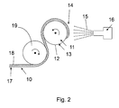
- Fig. 2 shows the production of a Ribletfolie with a roller 11 as a reference.
- the roller 11 has on the surface 12 in Fig. 2 for reasons of clarity not shown negative form of a Riblet Quilt 13th
- Metal particles 15 are accelerated to high speeds and collide with high kinetic energy on the surface 12 of the roller 11. By plastic deformation of the metal particles 15 and cold welding, the metal particles 15 combine to form a dense layer portion 14, so that a metallic material is formed.
- the rotation speed of the roller 11 determines the thickness of the layer portion 14.
- the metal particles 15 strike a previously formed layer, so that the layer portion 14 becomes thicker overall.
- the thickness of the layer section 14 depends on several factors, for example the circumference of the roller 11, the speed of the coating system relative to the width of the roller 11.
- the continuous riblet film 10 has a base 18 and a riblet structure 17, which in Fig. 2 for reasons of clarity are not shown, but comparable to the riblet 17 from Fig. 1 b are.
Landscapes
- Engineering & Computer Science (AREA)
- Manufacturing & Machinery (AREA)
- Mechanical Engineering (AREA)
- Chemical & Material Sciences (AREA)
- Composite Materials (AREA)
- Materials Engineering (AREA)
- Laminated Bodies (AREA)
- Other Surface Treatments For Metallic Materials (AREA)
Description
- Die vorliegende Erfindung betrifft eine Ribletfolie und ein Verfahren zu deren Herstellung. Insbesondere ist die Ribletfolie aus metallischem Material und wird schichtweise auf einer Bezugsform aufgebaut. Die Ribletfolie weist eine Ribletstruktur auf, die den Luftwiderstand reduziert.
- Die Verringerung des Treibstoffverbrauchs und die Reduzierung von Kohlenstoffdioxid / Stickstoffoxid (CO2/NOx) Emissionen sind wichtige zu erfüllende Ziele, insbesondere von der Luftfahrtindustrie oder Automobilindustrie. Neben Leichtbau zur Gewichtsreduzierung und Verbesserung des Wirkungsgrades von Antrieben, stellt die Reduzierung des Luftwiderstandes einen wesentlichen Baustein zur Erreichung dieser Ziele dar.
- Verfahren zur Herstellung von Oberflächen, die den Luftströmungswiderstand reduzieren, sind bekannt. Es ist seit langem bekannt und in Ölkanalversuchen nachgewiesen, dass durch geeignete Strukturierung von festen Oberflächen der Widerstand von darüber strömenden flüssigen oder gasförmigen Medien reduziert werden kann. Die Strukturierung der festen Oberfläche hat dabei unterschiedliche Formen und Größen. Aus Bechert, D.W. et al, Experiments on drag-reducing surfaces and their optimization with adjustable geometry, Journal of Fluid Mechanics, Vol. 338, pp. 59-97, 1997, ist bekannt eine strukturierte Kunststofffolie auf Körper aufzukleben.
- Basierend darauf wurden von Luftfahrtunternehmen wie Airbus und Boeing Versuche durchgeführt, bei denen Kunststofffolien entsprechender Strukturierung von der Firma 3M, auf die Außenfläche eines Flugzeugs aufgeklebt waren. Bei Flugversuchen mit einem Großflugzeug, dessen Oberfläche zu 70% mit einer solchen Kunststofffolie beklebt war, konnte eine Widerstandsverminderung von 2% nachgewiesen werden (Szodruch J., Dziomba, B., Aircraft Drag Reduction Technologies, 29th Aerospace Science Meeting, Reno, Nevada, 07-10 Jan. 1991). Dies führte zu einer Treibstoffersparnis von 1,5% (Roberts J.P., Drag Reduction: An Industrial Challenge, Special Course on Skin Friction Drag Reduction, AGARD Report 786, 1992).
- Die bislang verwendeten strukturierten Kunststofffolien haben aber nicht nur mangelnde mechanische Beständigkeit sondern weisen auch eine Degradation der Kunststofffolie und des Klebers auf, mit dem die Kunststofffolien am Flugzeug haften. Eine Folge der mangelnden mechanischen Beständigkeit ist beispielsweise die Verrundung des Spitzenradius einer sägezahnförmigen Strukturierung, die zu einer Aufhebung der reibungsvermindernden Wirkung führen kann. (Hage, W., Zur Widerstandsverminderung von dreidimensionalen Ribletstrukturen und anderer Oberflächen, Dissertation TU Berlin 2004). Die Degradation kann auch zu einer Ablösung der Kunststofffolien während des Betriebes führen.
- In einer noch nicht veröffentlichten Patentanmeldung der Anmelderin ist beschrieben, dass durch die Verwendung von strukturierten Metallfolien beispielsweise an einem Strukturbauteil eines Flugzeugs oder Helikopters, der Luftströmungswiderstand deutlich reduziert werden kann. Dazu weist die Struktur auf der Metallfolie Riblets auf, die mikroskopisch kleine Rillen auf der Oberfläche der Metallfolie sind. Solche strukturierten Metallfolien werden im Folgenden als Ribletfolie bezeichnet. Die mechanische Beständigkeit der Ribletfolie ist höher als bei Kunststofffolien. Bei der Verwendung von Ribletfolien auf faserverstärkten Kunststoffstrukturen ist gleichzeitig auch die elektrische Leitfähigkeit gegeben, um Blitzschutz bereitzustellen.
- Für die Herstellung von strukturierten Metallfolien ist beispielsweise aus
DE10314373A1 ein Feingussverfahren bekannt, mit dem Turbinenschaufeln aus Titanaluminiden (TiAl) mit strukturierter Oberfläche hergestellt werden. Auch ist die Strukturierung metallischer Oberflächen durch Laserbearbeitung oder Schleifen beispielsweise bekannt aus Oehlert et. Al., Exploratory Experiments on Machined Riblets for 2-D Compressor Blades, Proceeding of IMECE2007, 2007 ASME Internation Mechanical Engineering Congress and Exposition, November 11-15, 2007, Seattle, Washington, USA. - Eine solche direkte Strukturierung durch Gussverfahren oder abtragende Verfahren (Strukturierung durch Laser oder Mikrofräsen etc.) ist jedoch bei der erforderlichen Größe der Flächen der Flugzeuge, Helikopter oder anderem Fluggerät weder technisch noch wirtschaftlich anwendbar.
- Hingegen sind für die Herstellung von Ribletfolien in erforderlicher Menge und/oder Größe Fertigungsverfahren bekannt, bei denen Metallfolien durch mechanische Bearbeitung strukturiert werden. Beispielsweise sind dies mechanische (Um)Formverfahren wie Walzen (einschließlich inkrementeller Verfahren wie das sogenannte "incremental rolling") oder Prägen.
- Um bei diesen bekannten Fertigungsverfahren auf der Metallfolie scharfkantige Strukturen zu erzeugen, müssen die verwendeten Werkzeuge, beispielsweise Walzen, mit hohem Druck auf die Metallfolie gepresst werden. Solche Werkzeuge sind üblicherweise aus einem massiven Vollkörper gebildet, beispielsweise aus Stahl. Auch müssen solche Werkzeuge aus entsprechendem Material gefertigt sein, wenn beispielsweise erhöhte Temperaturen nötig sind, um die Metallfolie durch plastische Verformung so zu verändern, dass eine Ribletfolie entsteht. Hochfeste Werkstoffe wie beispielsweise beta-Titanlegierungen, deren Festigkeiten Werte bis zu 1700 MPa erreichen, können durch Umformdruck nicht mehr ausreichend plastifiziert werden, so dass die Ribletstruktur nicht oder nur grob auf der Metallfolie erzeugt werden kann.
- Aus der
WO 2010/017289 A1 sind Metallbleche und Metallplatten mit reibungsmindernden strukturierten Oberflächen und ein Herstellungsverfahren dazu bekannt. Dabei wird eine Aluminiumfolie mit Ribletstruktur offenbart, welche durch Walzen hergestellt wird. Die Oberfläche der so hergestellten Aluminium-Ribletfolie kann darüber hinaus durch eine Schutzschicht veredelt werden. - In der
WO 01/09405 A1 - Die
US 3 608 615 A bezieht sich auf eine Ablagerung von verdampftem Material auf einer Kondensationsfläche zur Folienbildung. Insbesondere beschreibt diese Veröffentlichung die kontinuierliche Kondensation von Metalldämpfen auf einer rotierenden Trommel und das kontinuierliche Abziehen der verfestigten Folie von der Trommel. Dabei wird allgemein die Herstellung von Metallfolien durch Sprühkompaktieren unter Verwendung einer Negativform beschrieben. - In der
JP 63 286563 A - Es ist Aufgabe der Erfindung, eine Ribletfolie und ein Verfahren zu deren Herstellung anzugeben, das die Nachteile des Stands der Technik überwindet und kostengünstig einsetzbar ist bei geringem technischen Aufwand.
- Diese Aufgabe wird mit einem Verfahren mit den Merkmalen des Anspruchs 1 gelöst. Bevorzugte Ausführungsformen sind in den abhängigen Ansprüchen angegeben. Eine Ribletfolie ist in Anspruch 9 angegeben.
- Der Erfindung liegt der Gedanke zugrunde, ein einfaches Verfahren zur Herstellung von metallischen Ribletfolien anzugeben, wobei die mechanischen und funktionellen Eigenschaften der Ribletfolie an die Erfordernisse der jeweiligen Anwendung durch geeignete Wahl der unterschiedlichsten Metalle und/oder -legierungen angepasst werden kann. Die Ribletfolie wird durch einen schichtweisen Aufbau auf einer Bezugsform hergestellt und von dieser dann abgelöst. Die Bezugsform weist auf wenigstens einer Fläche eine Struktur auf, die einer Negativform wenigstens einer Ribletstruktur entspricht. Die Negativform weist mikroskopisch kleine Vertiefungen auf der Fläche der Bezugsform auf. Nach dem Ablösen von der Bezugsform sind Riblets als mikroskopisch kleine Erhebungen/Spitzen auf der gebildeten Ribletfolie. Die Riblets können auf der gesamten Ribletfolie ausgebildet sein oder in ausgewählten Teilbereichen vorhanden sein. Entsprechend ist die Fläche der Bezugsform strukturiert.
- Mit anderen Worten ist es angedacht, unabhängig von der erforderlichen Größe, Form oder Beschaffenheit der Ribletfolie, ein einfaches Verfahren anzugeben wodurch aus einem beliebigem Metallpulver die gewünschte Form, Größe und Beschaffenheit der Ribletfolie hergestellt werden kann. Sowohl die Dicke der Ribletfolie selbst, als die Größe und Form der Riblets ist mit dem erfindungsgemäßen Verfahren variabel herstellbar. Vorteilhaft ist die Dicke der Ribletfolie weniger als 500 µm und hat vorteilhaft eine Dicke zwischen 50 - 400 µm, insbesondere mindestens 200 µm. Die Dicke der Ribletfolie gewährleistet bei geringst möglichem Gewicht eine einfache Anpassung an das jeweilige Bauteil auf dem sie aufgebracht wird.
- Erfindungsgemäß ist ein Verfahren vorgesehen, das zur Herstellung einer Ribletfolie dient, wobei die Ribletfolie schichtweise aufgebaut wird. Eine Bezugsform weist auf wenigstens einer Fläche eine Struktur auf, die einer Negativform wenigstens einer Ribletstruktur entspricht. Auf dieser Fläche wird wenigstens ein Schichtabschnitt aus einem Metallpulver so aufgebracht, dass sich ein metallischer Werkstoff bildet. Das Aufbringen weiterer Schichtabschnitte aus Metallpulver in vertikaler oder horizontaler Richtung auf der Fläche der Bezugsform kann beliebig oft wiederholt werden. Der so gebildete wenigstens eine Schichtabschnitt wird von der Bezugsform abgelöst, so dass die metallische Ribletfolie gebildet wird. Diese weist auf wenigstens einer Fläche eine Ribletstruktur auf.
- Das Pulver aus Metall oder Metalllegierung umfasst wenigstens alle Leichtmetalle in den Hauptgruppen oder Nebengruppen des Periodensystems, insbesondere Aluminium oder Titan und Mischungen hiervon, wobei auch verstärkende Partikel in das Metall/legierungspulver gemischt werden können, als auch Hartmetalle. Die Hartmetalle umfassen wenigstens einen Verbundwerkstoff aus einer Verstärkungsphase wie Wolframcarbid (WC) und einer Matrix oder Bindemittel wie Cobalt. Selbstverständlich umfassen die Metalle auch Metalllegierungen, die wenigstens eines der genannten Metalle einschließlich Kupfer, Zink, Lithium, Beryllium, Scandium, Vanadium oder Yttrium enthalten und insbesondere auch Stahllegierungen; bevorzugt Titan/-legierungen oder Stahllegierungen, insbesondere Aluminium/-legierungen.
- Die Bezugsform kann aus den verschiedensten Materialien gebildet sein. Bevorzugt ist die Bezugsform oder die Fläche, die die genannte Struktur aufweist, aus Materialien gebildet, die eine hohe Beständigkeit haben und sich kaum abnutzen, beispielsweise Stahl X45NiCrMo4, der bekanntermaßen für Präge und Umformwerkzeuge eingesetzt wird und gut polierbar ist.
- Die Fläche der Bezugsform umfasst eine Struktur die einer Negativform wenigstens einer Ribletstruktur entspricht, die durch mehrere trapezförmige, halbkreisförmige, stromlinienförmige und/oder sägezahnförmige Riblets oder eine Kombination hiervon gebildet ist. Die Negativform der Riblets umfassen einen Größenbereich mit einer Ribletbreite von etwa 20 µm bis 130 µm, bevorzugt 30 µm bis 80 µm, insbesondere 50 µm bis 60 µm, speziell 60 µm. Wenigstens eine Negativform eines Riblets weist eine Höhe auf, die halb so groß ist wie der Abstand zu einem ihm benachbarten Riblet.
- Das Aufbringen eines Schichtabschnitts auf der Fläche der Bezugsform erfolgt schichtweise. Nach und nach können eine oder mehrere Schichten aus gleichem oder verschiedenem Metallpulver aufgebracht werden. Vorteilhafterweise kann der erste Schichtabschnitt aus einem Titanpulver (oder Titanlegierung) aufgebracht werden und die restlichen Schichtabschnitte aus Aluminiumpulver. Die so gebildete Ribletfolie hat sehr robuste beständige Riblets und eine Basis die kostengünstig aus Aluminium hergestellt ist. Zudem kann Aluminium durch dem Fachmann bekannte Verfahren wie Anodisieren mit einer für eine Verklebung ideal geeigneten Oberfläche ausgestattet werden.
- Die Beschaffenheit der strukturierten Fläche, insbesondere die gute Polierbarkeit, ermöglicht ein einfaches Lösen der(s) aufgebrachten Schichtabschnitte(s) von der Bezugsform.
- Das Aufbringen des Metallpulvers auf das Bezugsformstück erfolgt bevorzugt durch Aufspritzen des Metallpulvers. Beispielsweise wird das Metallpulver schichtweise aufgetragen durch Kaltgasspritzen ("cold gas spray"), thermokinetisches Spritzen (z.B. Flamecon® der Firma Leoni), plasmaunterstütztes Auftragen (z.B. Plasmadust® der Firma Reinhausen Plasma) oder bekannte thermische Spritzverfahren wie Flammspritzen, Plasmaspritzen oder HVOF (High Velocity Oxygen Fuel). Hierbei ist es möglich Strukturen mit Geometrien von wenigen µm zu bilden. Die gebildeten Ribletstrukturen umfassen einen Größenbereich mit einer Ribletbreite von etwa 20 µm bis 130 µm, bevorzugt 30 µm bis 80 µm, insbesondere 50 µm bis 60 µm. Die Riblethöhe umfasst einen Bereich von 50-100% der Ribletbreite. Die Riblethöhe kann gleich Ribletbreite sein oder eine Kombination aus einem der angegebenen Größenbereiche umfassen. Entsprechend ist die Struktur der Negativform auf der Bezugsform ausgebildet.
- Beim Aufbau des wenigstens einen Schichtabschnitts durch Aufspritzen wird das Metallpulver mit hoher Energie auf die Fläche der Bezugsform beschleunigt. Beim Aufprall der Metallpartikel verbinden sich diese durch plastische Verformung oder Kaltverschweissung zu einem metallischen Werkstoff. Beim Kaltgasprozess wird dazu ein aufgeheiztes Gas beschleunigt und das Metallpulver wird in den Gasstrahl injiziert und durch diesen beschleunigt. Beim Plasmaspritzen als Beispiel thermischer Spritzverfahren wird in einer normalen oder inerten Atmosphäre oder Vakuum ein Lichtbogen zwischen der Kathode und Anode des Plasmabrenners erzeugt. Das durch den Plasmabrenner strömende Gas wird durch den Lichtbogen geleitet und ionisiert. In dieses aufgeheizte Gas wird das Metallpulver eingedüst und durch die hohe Plasmatemperatur geschmolzen/plastifiziert. Der Plasmastrom beschleunigt die Metallpartikel in Richtung Fläche der Bezugsform. Nach dem Aufprall verbinden sich die Metallpartikel zu einer dichten, miteinander fest haftenden Schicht durch plastische Verformung und/oder Kaltverschweissung bzw Erstarrun.
- Das Aufspritzen des wenigstens einen Schichtabschnitts hat den Vorteil, dass eine viel höhere Abscheiderate auf der Bezugsform erzielt werden kann als im Stand der Technik bei einer galvanischen Abscheidung beispielsweise. Dies ermöglicht eine wirtschaftlich rentable Herstellung insbesondere von großen Ribletfolien, beispielsweise für die Tragfläche eines Flugzeugs wie der A380 der Firma Airbus Operations GmbH. Auch kann nahezu jedes Metallpulver verwendet werden, wobei die Korngröße variieren kann und der Größe der Riblettstruktur entsprechend von wenigen nm bis mehreren hundert µm ausgewählt wird.
- Der wenigstens eine Schichtabschnitt kann eine unterschiedliche Dicke aufweisen. Die Schichtdicke kann variabel sein, beispielsweise können die Randbereiche dicker oder dünner als die Mitte des Schichtabschnitts gebildet sein. Auch kann der gesamte Schichtabschnitt mit einer im Wesentlichen konstanten Dicke gebildet werden.
- Die Bezugsform kann einmalig verwendet werden oder für mehrfachen Gebrauch vorgesehen sein. Eine wiederverwendbare Bezugsform ist kostengünstig und kann für die Herstellung von Ribletfolien aus verschiedenen Metallpulvern dienen, wobei die Ribletstruktur identisch ist.
- In einem weiteren Ausführungsbeispiel ist die Bezugsform als Walze ausgebildet. Dies ermöglicht eine kontinierliche Herstellung der erfindungsgemäßen Ribletfolie.
- Vorteilhafterweise kann die Dicke der Ribletfolie über die Umdrehungsgeschwindigkeit der Walze eingestellt werden. Bei niedriger Umdrehungsgeschwindigkeit wird eine Dicke von beispielsweise 400 µm gebildet. Soll die Ribletfolie hingegen dünn sein, beispielsweise 200 µm wird die Umdrehungsgeschwindigkeit der Walze einfach erhöht. Dadurch wird eine einfache Regelung der Dicke der Ribletfolie ermöglicht.
- Die metallische Ribletfolie kann zumindest teilweise veredelt werden. Dies umfasst beispielsweise eine Rückseitenbeschichtung mit einem Kleber, die Funktionalisierung der Oberflächen durch eine Beschichtung oder eine Modifizierung der Oberfläche, so dass diese schmutzabweisend oder vereisungsverhindernd sind.
- Nachfolgend wird die Erfindung beispielhaft anhand von in den Figuren dargestellten Ausführungsbeispielen beschrieben. Zum einfacheren Verständnis wurde auf eine maßstabsgetreue Wiedergabe verzichtet.
-
Fig. 1 a zeigt die Herstellung einer Ribletfolie nach einem ersten Ausführungsbeispiel; -
Fig. 1 b zeigt die abgelöste Ribletfolie mit trapezförmiger Ribletstruktur; -
Fig. 2 zeigt die Herstellung einer Ribletfolie nach einem zweiten Ausführungsbeispiel. - In
Fig. 1a ist skizzenhaft die Herstellung einer Ribletfolie gezeigt. Eine Bezugsform 11 weist auf einer Fläche 12 eine Ribletstruktur 13 auf. Mit einer Beschichtungsanlage 16 werden Metallpartikel 15 eines Metallpulvers mit hoher Geschwindigkeit zur Fläche 12 beschleunigt. Beim Aufprall verformen sich die Metallpartikel 15 und verbinden sich zu einem metallischen Werkstoff. Beim kontinuierlichen Aufspritzen von Metallpartikeln 15 auf die Fläche 12 wird schichtweise der Schichtabschnitt 14 aufgebaut. Das Aufspritzen des Metallpulvers wird beendet, wenn die Dicke des Schichtabschnitts 14 die für eine Anwendung erforderliche Dicke erreicht hat. - Die Beschichtungsanlage 16 ist in diesem Ausführungsbeispiel eine Anlage für Kaltgasspritzen. Ein Trägergas wird komprimiert und durch Entspannung in einer Düse auf eine Geschwindigkeit beschleunigt, die unterhalb der Schallgeschwindigkeit des Trägergases liegt. Das Metallpulver wird in den Gasstrahl injiziert. Das Trägergas hat eine Temperatur die unterhalb der Schmelztemperatur der Metallpartikel 15 liegt, so dass diese nicht schmelzen. Die Metallpartikel 15 verformen sich beim Aufprall auf die Fläche 14, wobei die daraus resultierende lokale Wärmefreigabe für Kohäsion und Haftung für die Bildung der Schichtabschnitt 14 sorgen, so dass ein metallischer Werkstoff gebildet wird.
-
Fig. 1 b zeigt die abgelöste Ribletfolie mit trapezförmiger Ribletstruktur. - Die Ribletfolie 10 hat eine Basis 18 sowie eine Ribletstruktur 17 mit trapezförmigen Riblets. Die Bezugsform 11 ist wiederverwendbar zur Herstellung einer weiteren metallischen Ribletfolie 10.
-
Fig. 2 zeigt die Herstellung einer Ribletfolie mit einer Walze 11 als Bezugsform. Die Walze 11 hat auf der Fläche 12 eine inFig. 2 aus Gründen der Übersicht nicht gezeigte Negativform einer Ribletstruktur 13. - Mit der Beschichtungsanlage 16, wie bei
Fig. 1 beschrieben, werden Metallpartikel 15 auf hohe Geschwindigkeiten beschleunigt und prallen mit hoher kinetischer Energie auf die Fläche 12 der Walze 11. Durch plastische Verformung der Metallpartikel 15 und Kaltverschweissung verbinden sich die Metallpartikel 15 zu einem dichten Schichtabschnitt 14, so dass ein metallischer Werkstoff gebildet wird. - Die Umdrehungsgeschwindigkeit der Walze 11 bestimmt die Dicke des Schichtabschnitts 14. Wenn die Umdrehungsgeschwindigkeit der Walze 11 niedrig ist, treffen die Metallpartikel 15 auf eine zuvor gebildete Schicht, so dass der Schichtabschnitt 14 insgesamt dicker wird. Die Dicke des Schichtabschnitts 14 hängt von mehreren Faktoren ab, beispielsweise der Umfang der Walze 11, die Geschwindigkeit der Beschichtungsanlage relativ zur Breite der Walze 11.
- Bei kontinuierlicher Drehung der Walze 11 und Aufspritzen des Metallpulvers durch die Beschichtungsanlage 16 wird ein kontinuierlicher Schichtabschnitt 14 hergestellt. Dieser wird von einer Abrollwalze 19 aufgenommen und durch Drehen der Abrollwalze 19 entgegen dem Drehsinn der Walze 11 von dieser abgelöst.
- Die kontinuierliche Ribletfolie 10 hat eine Basis 18 und eine Ribletstruktur 17, die in
Fig. 2 aus Gründen der Übersichtlichkeit nicht gezeigt sind, jedoch vergleichbar mit der Ribletstruktur 17 ausFig. 1 b sind. -
- 10
- Ribletfolie
- 11
- Bezugsform, Walze
- 12
- Fläche
- 13
- Ribletstruktur
- 14
- Schichtabschnitt
- 15
- Metallpartikel
- 16
- Beschichtungsanlage
- 17
- Ribletstruktur
- 18
- Basis
- 19
- Abrollwalze
Claims (9)
- Verfahren zur Herstellung einer metallischen Ribletfolie (10) durch schichtweisen Aufbau, wobei die Ribletfolie (10) durch zumindest einmaliges Durchführen der folgenden Schritte aufgebaut wird, umfassend:- Bereitstellen einer Bezugsform (11), die auf wenigstens einer Fläche (12) eine Struktur aufweist, die einer Negativform wenigstens einer Ribletstruktur (13) entspricht;- Aufbringen wenigstens eines Schichtabschnitts (14) aus einem Metallpulver auf der wenigstens einen Fläche (12) der Bezugsform (11) in solcher Weise, dass sich der wenigstens eine Schichtabschnitt (14) als metallischer Werkstoff bildet;- Lösen des wenigstens einen Schichtabschnitts (14) von der Bezugsform (11), so dass die metallische Ribletfolie (10) gebildet wird, die auf wenigstens einer Fläche eine Ribletstruktur (10) aufweist.
- Verfahren nach Anspruch 1, dadurch gekennzeichnet, dass das Aufbringen des wenigstens einen Schichtabschnitts (14) durch Aufspritzen eines Metallpulvers gebildet wird.
- Verfahren nach Anspruch 1 oder 2, dadurch gekennzeichnet, dass ein erster Schichtabschnitt (14) aus einem Metallpulver aufgebracht wird, das Titan oder dessen Legierungen umfasst und ein zweiter Schichtabschnitt (14) aus einem Metallpulver aufgebracht wird, das Aluminium oder dessen Legierungen umfasst.
- Verfahren nach einem der vorangehenden Ansprüche, dadurch gekennzeichnet, dass die Dicke des wenigstens einen Schichtabschnitts (14) unterschiedlich ist.
- Verfahren nach einem der vorangehenden Ansprüche, dadurch gekennzeichnet, dass die Bezugsform (11) wiederverwendbar ist.
- Verfahren nach einem der vorangehenden Ansprüche, dadurch gekennzeichnet, dass die Bezugsform (11) als Walze (11) ausgebildet ist.
- Verfahren nach Anspruch 6, dadurch gekennzeichnet, dass die Dicke des wenigstens einen Schichtabschnitts (14) über die Umdrehungsgeschwindigkeit der Walze (11) einstellbar ist.
- Verfahren nach einem der vorangehenden Ansprüche, dadurch gekennzeichnet, dass die Oberfläche der metallischen Ribletfolie (10) zumindest teilweise veredelt wird.
- Ribletfolie (10), deren wenigstens eine Fläche eine Struktur aufweist, die den Luftströmungswiderstand reduziert, wobei die Ribletfolie (10) hergestellt ist mit einem Verfahren nach einem der vorangehenden Ansprüche.
Applications Claiming Priority (2)
| Application Number | Priority Date | Filing Date | Title |
|---|---|---|---|
| DE102011114832A DE102011114832A1 (de) | 2011-10-05 | 2011-10-05 | Ribletfolie und verfahren zu deren herstellung |
| PCT/DE2012/000960 WO2013050018A1 (de) | 2011-10-05 | 2012-10-02 | Ribletfolie und verfahren zu deren herstellung |
Publications (2)
| Publication Number | Publication Date |
|---|---|
| EP2773476A1 EP2773476A1 (de) | 2014-09-10 |
| EP2773476B1 true EP2773476B1 (de) | 2016-03-02 |
Family
ID=47115087
Family Applications (1)
| Application Number | Title | Priority Date | Filing Date |
|---|---|---|---|
| EP12780401.1A Active EP2773476B1 (de) | 2011-10-05 | 2012-10-02 | Ribletfolie und verfahren zu deren herstellung |
Country Status (6)
| Country | Link |
|---|---|
| US (1) | US20140356219A1 (de) |
| EP (1) | EP2773476B1 (de) |
| CN (1) | CN103987478A (de) |
| DE (1) | DE102011114832A1 (de) |
| ES (1) | ES2575243T3 (de) |
| WO (1) | WO2013050018A1 (de) |
Cited By (2)
| Publication number | Priority date | Publication date | Assignee | Title |
|---|---|---|---|---|
| DE102018126796A1 (de) * | 2018-10-26 | 2020-04-30 | Airbus Defence and Space GmbH | Metallwerkstoff und Verfahren für die Herstellung eines Bauteils oder Halbzeugs, sowie Halbzeug und Bauteil, insbesondere für die Luft- und Raumfahrt |
| DE102021006346A1 (de) | 2021-12-22 | 2023-06-22 | Kaco Gmbh + Co. Kg | Verfahren zur Herstellung von Dichtringen einer Gleitringdichtung |
Families Citing this family (20)
| Publication number | Priority date | Publication date | Assignee | Title |
|---|---|---|---|---|
| DE102013013817A1 (de) | 2013-08-22 | 2015-02-26 | Airbus Defence and Space GmbH | Strukturbauteil mit einer Ribletoberfläche |
| DE102015201927A1 (de) * | 2015-02-04 | 2016-08-04 | Siemens Aktiengesellschaft | Verfahren zum Kaltgasspritzen mit Maske |
| US9868135B2 (en) | 2015-05-06 | 2018-01-16 | The Boeing Company | Aerodynamic microstructures having sub-microstructures |
| US9751618B2 (en) | 2015-05-06 | 2017-09-05 | The Boeing Company | Optical effects for aerodynamic microstructures |
| US9714083B2 (en) | 2015-05-06 | 2017-07-25 | The Boeing Company | Color applications for aerodynamic microstructures |
| US10107302B2 (en) | 2015-12-10 | 2018-10-23 | General Electric Company | Durable riblets for engine environment |
| US10105877B2 (en) | 2016-07-08 | 2018-10-23 | The Boeing Company | Multilayer riblet applique and methods of producing the same |
| US10322436B2 (en) | 2016-10-06 | 2019-06-18 | Nano And Advanced Materials Institute Limited | Method of coating interior surfaces with riblets |
| US10519552B2 (en) | 2016-12-22 | 2019-12-31 | United Technologies Corporation | Deposited material structure with integrated component |
| US10363634B2 (en) | 2016-12-22 | 2019-07-30 | United Technologies Corporation | Deposited structure with integral cooling enhancement features |
| US10648084B2 (en) | 2016-12-22 | 2020-05-12 | United Technologies Corporation | Material deposition to form a sheet structure |
| US20180179639A1 (en) * | 2016-12-22 | 2018-06-28 | United Technologies Corporation | Modular tooling for a deposited structure |
| US20180178331A1 (en) * | 2016-12-22 | 2018-06-28 | United Technologies Corporation | Reinforcement of a deposited metallic structure using reinforcing particles |
| US10907256B2 (en) | 2016-12-22 | 2021-02-02 | Raytheon Technologies Corporation | Reinforcement of a deposited structure forming a metal matrix composite |
| US10563310B2 (en) | 2016-12-22 | 2020-02-18 | United Technologies Corporation | Multi-wall deposited thin sheet structure |
| US11047239B2 (en) | 2018-12-03 | 2021-06-29 | General Electric Company | Method of forming a cure tool and method of forming a textured surface using a cure tool |
| DE102019105191A1 (de) * | 2019-02-28 | 2020-09-03 | Prominent Gmbh | Verdrängerpumpe mit strömungsbegünstigten Oberflächen |
| KR102231057B1 (ko) * | 2019-12-09 | 2021-03-23 | 한국전자기술연구원 | 재생성이 용이한 자동차 표면의 생체모방 인공구조물 생성 시스템 및 방법 |
| US11618511B2 (en) | 2021-01-12 | 2023-04-04 | Honda Motor Co., Ltd. | Surface pattern for a vehicle |
| US11987021B2 (en) | 2021-09-01 | 2024-05-21 | The Boeing Company | Multilayer riblet appliques |
Family Cites Families (16)
| Publication number | Priority date | Publication date | Assignee | Title |
|---|---|---|---|---|
| US3608615A (en) * | 1970-08-20 | 1971-09-28 | Phelps Dodge Corp | Foil production |
| JPS63286563A (ja) * | 1987-05-15 | 1988-11-24 | Yamaki Kogyo Kk | 薄肉成型品の製造方法 |
| GB9116242D0 (en) * | 1991-07-27 | 1991-09-11 | British Steel Plc | Method and apparatus for producing strip products by a spray forming technique |
| DE19608719A1 (de) * | 1996-03-06 | 1997-09-11 | Deutsche Forsch Luft Raumfahrt | Verfahren zur Herstellung von Formteilen |
| US6043451A (en) * | 1997-11-06 | 2000-03-28 | Promet Technologies, Inc. | Plasma spraying of nickel-titanium compound |
| NL1014924C2 (nl) * | 1999-07-30 | 2001-02-01 | Chromalloy Holland B V | Beperking van de luchtweerstand voor componenten van een gasturbine motor. |
| US6641767B2 (en) * | 2000-03-10 | 2003-11-04 | 3M Innovative Properties Company | Methods for replication, replicated articles, and replication tools |
| DE10314373A1 (de) | 2003-03-28 | 2004-10-07 | Rwth Aachen | Urfomverfahren für ein Bauteil mit Mikrostruktur-Funktionselement |
| CN100528425C (zh) * | 2007-11-22 | 2009-08-19 | 上海交通大学 | 活泼金属钛和碳化硼复合球形热喷涂粉末的制备方法 |
| CN102138009B (zh) * | 2008-08-05 | 2014-05-28 | 美铝公司 | 具有摩擦力降低的织构化表面的金属薄板和中厚板及其制造方法 |
| CN101487130B (zh) * | 2009-01-06 | 2010-09-22 | 北京航空航天大学 | 采用脉冲电铸方法制作有鳞生物表皮形貌复制模板的复制方法 |
| US8668166B2 (en) * | 2009-01-29 | 2014-03-11 | The Boeing Company | Shape memory riblets |
| US8684310B2 (en) * | 2009-01-29 | 2014-04-01 | The Boeing Company | Rigid tipped riblets |
| US8720047B2 (en) * | 2009-05-08 | 2014-05-13 | Hoowaki, Llc | Method for making microstructured objects |
| WO2010138132A1 (en) * | 2009-05-26 | 2010-12-02 | The Board Of Trustees Of The University Of Illinois | Casting microstructures into stiff and durable materials from a flexible and reusable mold |
| CN201925268U (zh) * | 2010-11-09 | 2011-08-10 | 林瑞麟 | 降低物体行进阻力的结构 |
-
2011
- 2011-10-05 DE DE102011114832A patent/DE102011114832A1/de not_active Withdrawn
-
2012
- 2012-10-02 EP EP12780401.1A patent/EP2773476B1/de active Active
- 2012-10-02 ES ES12780401.1T patent/ES2575243T3/es active Active
- 2012-10-02 WO PCT/DE2012/000960 patent/WO2013050018A1/de not_active Ceased
- 2012-10-02 CN CN201280059919.7A patent/CN103987478A/zh active Pending
- 2012-10-02 US US14/350,335 patent/US20140356219A1/en not_active Abandoned
Cited By (2)
| Publication number | Priority date | Publication date | Assignee | Title |
|---|---|---|---|---|
| DE102018126796A1 (de) * | 2018-10-26 | 2020-04-30 | Airbus Defence and Space GmbH | Metallwerkstoff und Verfahren für die Herstellung eines Bauteils oder Halbzeugs, sowie Halbzeug und Bauteil, insbesondere für die Luft- und Raumfahrt |
| DE102021006346A1 (de) | 2021-12-22 | 2023-06-22 | Kaco Gmbh + Co. Kg | Verfahren zur Herstellung von Dichtringen einer Gleitringdichtung |
Also Published As
| Publication number | Publication date |
|---|---|
| ES2575243T3 (es) | 2016-06-27 |
| WO2013050018A1 (de) | 2013-04-11 |
| DE102011114832A1 (de) | 2013-04-11 |
| US20140356219A1 (en) | 2014-12-04 |
| EP2773476A1 (de) | 2014-09-10 |
| CN103987478A (zh) | 2014-08-13 |
Similar Documents
| Publication | Publication Date | Title |
|---|---|---|
| EP2773476A1 (de) | Ribletfolie und verfahren zu deren herstellung | |
| EP0623466B1 (de) | Druckwalze mit einer Hülse aus thermisch gewickelten faserverstärkten Thermoplasten und einer plasmagespritzten Kupfer- oder Kupferlegierungsbeschichtung | |
| DE60210267T2 (de) | Vorrichtung und verfahren zur festkörper aufbringung und verdichtung von pulverteilchen mittels hochgeschwindigkeit und thermisch plastischer verformung | |
| DE102008042237B4 (de) | Metallische Beschichtung | |
| EP2732072B1 (de) | Verfahren zum reparieren einer schadstelle in einem gussteil und verfahren zum erzeugen eines geeigneten reparaturmaterials | |
| EP2467224A1 (de) | Dünnwandiges strukturbauteil und verfahren zu seiner herstellung | |
| DE102015115963A1 (de) | Verfahren und Vorrichtung zur additiven Fertigung eines Formkörpers aus einem metallischen Werkstoffgemisch | |
| EP0911426B1 (de) | Herstellung von Formteilen | |
| DE102009048706A1 (de) | Verfahren und Vorrichtung zur Herstellung eines Formteils mittels generativen Auftragens | |
| DE102016113246A1 (de) | Verfahren und Vorrichtung zur Erzeugung eines metallischen Werkstoffgemischs bei der additiven Fertigung | |
| EP2009132A1 (de) | Verfahren zur Herstellung einer funktionalen Schicht, Beschichtungsmaterial, Verfahren zu seiner Herstellung sowie funktionale Schicht | |
| EP2499279A1 (de) | Beschichten von kunststoffbauteilen mittels kinetischen kaltgasspritzens | |
| WO2008067961A2 (de) | Verfahren zum herstellen eines formwerkzeugs mit einer verschleissschutzschicht | |
| WO2008067959A1 (de) | Verfahren zum herstellen eines formwerkzeugs | |
| EP2343143A2 (de) | Verfahren zur Fertigung von Bauteilen aus Refraktärmetallen | |
| EP2617868B1 (de) | Verfahren und Vorrichtung zum thermischen Spritzen | |
| EP2565290B1 (de) | Ballistisches Schutzsystem | |
| DE102010005897A1 (de) | Verfahren zum Herstellen eines Körpers mittels Sprühkompaktieren und mittels Sprühkompaktieren hergestellter Körper | |
| EP1765536B1 (de) | Verfahren zum herstellen von erzeugnissen aus metall | |
| EP3819106A1 (de) | Verfahren zur herstellung eines verbundbauteils, das mit einem faserver-stärktem kunststoffbauteil, an dem mindestens eine oberfläche mit einer beschichtung ausgebildet ist, gebildet ist | |
| DE102012020814A1 (de) | Verfahren und Vorrichtung zum Aufbringen eines Zusatzwerkstoffs auf ein Werkstück | |
| EP3141632A1 (de) | Verfahren zum verbinden von werkstücken und mit diesem verfahren hergestellte verbindungsstücke | |
| EP0911423A1 (de) | Verbinden von Werkstücken | |
| DE10246454A1 (de) | Herstellung beschichteter geschäumter Bauteile und Bauteile mit keramischer oder Hartstoffbeschichtung | |
| DE4313077C2 (de) | Verfahren zur Herstellung langfaserverstärkter Metallverbundkörper, Metallverbundkörper und Verwendung desselben |
Legal Events
| Date | Code | Title | Description |
|---|---|---|---|
| PUAI | Public reference made under article 153(3) epc to a published international application that has entered the european phase |
Free format text: ORIGINAL CODE: 0009012 |
|
| 17P | Request for examination filed |
Effective date: 20140430 |
|
| AK | Designated contracting states |
Kind code of ref document: A1 Designated state(s): AL AT BE BG CH CY CZ DE DK EE ES FI FR GB GR HR HU IE IS IT LI LT LU LV MC MK MT NL NO PL PT RO RS SE SI SK SM TR |
|
| RAP1 | Party data changed (applicant data changed or rights of an application transferred) |
Owner name: AIRBUS DEFENCE AND SPACE GMBH |
|
| DAX | Request for extension of the european patent (deleted) | ||
| GRAP | Despatch of communication of intention to grant a patent |
Free format text: ORIGINAL CODE: EPIDOSNIGR1 |
|
| INTG | Intention to grant announced |
Effective date: 20150814 |
|
| GRAS | Grant fee paid |
Free format text: ORIGINAL CODE: EPIDOSNIGR3 |
|
| GRAA | (expected) grant |
Free format text: ORIGINAL CODE: 0009210 |
|
| AK | Designated contracting states |
Kind code of ref document: B1 Designated state(s): AL AT BE BG CH CY CZ DE DK EE ES FI FR GB GR HR HU IE IS IT LI LT LU LV MC MK MT NL NO PL PT RO RS SE SI SK SM TR |
|
| REG | Reference to a national code |
Ref country code: GB Ref legal event code: FG4D Free format text: NOT ENGLISH |
|
| REG | Reference to a national code |
Ref country code: AT Ref legal event code: REF Ref document number: 777647 Country of ref document: AT Kind code of ref document: T Effective date: 20160315 Ref country code: CH Ref legal event code: EP |
|
| REG | Reference to a national code |
Ref country code: IE Ref legal event code: FG4D Free format text: LANGUAGE OF EP DOCUMENT: GERMAN |
|
| REG | Reference to a national code |
Ref country code: DE Ref legal event code: R096 Ref document number: 502012006173 Country of ref document: DE |
|
| REG | Reference to a national code |
Ref country code: ES Ref legal event code: FG2A Ref document number: 2575243 Country of ref document: ES Kind code of ref document: T3 Effective date: 20160627 |
|
| REG | Reference to a national code |
Ref country code: NL Ref legal event code: MP Effective date: 20160302 |
|
| REG | Reference to a national code |
Ref country code: LT Ref legal event code: MG4D |
|
| PG25 | Lapsed in a contracting state [announced via postgrant information from national office to epo] |
Ref country code: NO Free format text: LAPSE BECAUSE OF FAILURE TO SUBMIT A TRANSLATION OF THE DESCRIPTION OR TO PAY THE FEE WITHIN THE PRESCRIBED TIME-LIMIT Effective date: 20160602 Ref country code: FI Free format text: LAPSE BECAUSE OF FAILURE TO SUBMIT A TRANSLATION OF THE DESCRIPTION OR TO PAY THE FEE WITHIN THE PRESCRIBED TIME-LIMIT Effective date: 20160302 Ref country code: HR Free format text: LAPSE BECAUSE OF FAILURE TO SUBMIT A TRANSLATION OF THE DESCRIPTION OR TO PAY THE FEE WITHIN THE PRESCRIBED TIME-LIMIT Effective date: 20160302 Ref country code: GR Free format text: LAPSE BECAUSE OF FAILURE TO SUBMIT A TRANSLATION OF THE DESCRIPTION OR TO PAY THE FEE WITHIN THE PRESCRIBED TIME-LIMIT Effective date: 20160603 |
|
| PG25 | Lapsed in a contracting state [announced via postgrant information from national office to epo] |
Ref country code: NL Free format text: LAPSE BECAUSE OF FAILURE TO SUBMIT A TRANSLATION OF THE DESCRIPTION OR TO PAY THE FEE WITHIN THE PRESCRIBED TIME-LIMIT Effective date: 20160302 Ref country code: PL Free format text: LAPSE BECAUSE OF FAILURE TO SUBMIT A TRANSLATION OF THE DESCRIPTION OR TO PAY THE FEE WITHIN THE PRESCRIBED TIME-LIMIT Effective date: 20160302 Ref country code: SE Free format text: LAPSE BECAUSE OF FAILURE TO SUBMIT A TRANSLATION OF THE DESCRIPTION OR TO PAY THE FEE WITHIN THE PRESCRIBED TIME-LIMIT Effective date: 20160302 Ref country code: LT Free format text: LAPSE BECAUSE OF FAILURE TO SUBMIT A TRANSLATION OF THE DESCRIPTION OR TO PAY THE FEE WITHIN THE PRESCRIBED TIME-LIMIT Effective date: 20160302 Ref country code: LV Free format text: LAPSE BECAUSE OF FAILURE TO SUBMIT A TRANSLATION OF THE DESCRIPTION OR TO PAY THE FEE WITHIN THE PRESCRIBED TIME-LIMIT Effective date: 20160302 Ref country code: RS Free format text: LAPSE BECAUSE OF FAILURE TO SUBMIT A TRANSLATION OF THE DESCRIPTION OR TO PAY THE FEE WITHIN THE PRESCRIBED TIME-LIMIT Effective date: 20160302 |
|
| REG | Reference to a national code |
Ref country code: FR Ref legal event code: PLFP Year of fee payment: 5 |
|
| PG25 | Lapsed in a contracting state [announced via postgrant information from national office to epo] |
Ref country code: EE Free format text: LAPSE BECAUSE OF FAILURE TO SUBMIT A TRANSLATION OF THE DESCRIPTION OR TO PAY THE FEE WITHIN THE PRESCRIBED TIME-LIMIT Effective date: 20160302 Ref country code: IS Free format text: LAPSE BECAUSE OF FAILURE TO SUBMIT A TRANSLATION OF THE DESCRIPTION OR TO PAY THE FEE WITHIN THE PRESCRIBED TIME-LIMIT Effective date: 20160702 |
|
| PG25 | Lapsed in a contracting state [announced via postgrant information from national office to epo] |
Ref country code: PT Free format text: LAPSE BECAUSE OF FAILURE TO SUBMIT A TRANSLATION OF THE DESCRIPTION OR TO PAY THE FEE WITHIN THE PRESCRIBED TIME-LIMIT Effective date: 20160704 Ref country code: RO Free format text: LAPSE BECAUSE OF FAILURE TO SUBMIT A TRANSLATION OF THE DESCRIPTION OR TO PAY THE FEE WITHIN THE PRESCRIBED TIME-LIMIT Effective date: 20160302 Ref country code: SK Free format text: LAPSE BECAUSE OF FAILURE TO SUBMIT A TRANSLATION OF THE DESCRIPTION OR TO PAY THE FEE WITHIN THE PRESCRIBED TIME-LIMIT Effective date: 20160302 Ref country code: CZ Free format text: LAPSE BECAUSE OF FAILURE TO SUBMIT A TRANSLATION OF THE DESCRIPTION OR TO PAY THE FEE WITHIN THE PRESCRIBED TIME-LIMIT Effective date: 20160302 Ref country code: SM Free format text: LAPSE BECAUSE OF FAILURE TO SUBMIT A TRANSLATION OF THE DESCRIPTION OR TO PAY THE FEE WITHIN THE PRESCRIBED TIME-LIMIT Effective date: 20160302 |
|
| REG | Reference to a national code |
Ref country code: DE Ref legal event code: R097 Ref document number: 502012006173 Country of ref document: DE |
|
| PG25 | Lapsed in a contracting state [announced via postgrant information from national office to epo] |
Ref country code: IT Free format text: LAPSE BECAUSE OF FAILURE TO SUBMIT A TRANSLATION OF THE DESCRIPTION OR TO PAY THE FEE WITHIN THE PRESCRIBED TIME-LIMIT Effective date: 20160302 |
|
| PLBE | No opposition filed within time limit |
Free format text: ORIGINAL CODE: 0009261 |
|
| STAA | Information on the status of an ep patent application or granted ep patent |
Free format text: STATUS: NO OPPOSITION FILED WITHIN TIME LIMIT |
|
| PG25 | Lapsed in a contracting state [announced via postgrant information from national office to epo] |
Ref country code: DK Free format text: LAPSE BECAUSE OF FAILURE TO SUBMIT A TRANSLATION OF THE DESCRIPTION OR TO PAY THE FEE WITHIN THE PRESCRIBED TIME-LIMIT Effective date: 20160302 |
|
| 26N | No opposition filed |
Effective date: 20161205 |
|
| PG25 | Lapsed in a contracting state [announced via postgrant information from national office to epo] |
Ref country code: BE Free format text: LAPSE BECAUSE OF NON-PAYMENT OF DUE FEES Effective date: 20161031 Ref country code: BG Free format text: LAPSE BECAUSE OF FAILURE TO SUBMIT A TRANSLATION OF THE DESCRIPTION OR TO PAY THE FEE WITHIN THE PRESCRIBED TIME-LIMIT Effective date: 20160602 Ref country code: SI Free format text: LAPSE BECAUSE OF FAILURE TO SUBMIT A TRANSLATION OF THE DESCRIPTION OR TO PAY THE FEE WITHIN THE PRESCRIBED TIME-LIMIT Effective date: 20160302 |
|
| REG | Reference to a national code |
Ref country code: CH Ref legal event code: PL |
|
| REG | Reference to a national code |
Ref country code: IE Ref legal event code: MM4A |
|
| PG25 | Lapsed in a contracting state [announced via postgrant information from national office to epo] |
Ref country code: CH Free format text: LAPSE BECAUSE OF NON-PAYMENT OF DUE FEES Effective date: 20161031 Ref country code: LI Free format text: LAPSE BECAUSE OF NON-PAYMENT OF DUE FEES Effective date: 20161031 |
|
| PG25 | Lapsed in a contracting state [announced via postgrant information from national office to epo] |
Ref country code: LU Free format text: LAPSE BECAUSE OF NON-PAYMENT OF DUE FEES Effective date: 20161002 |
|
| REG | Reference to a national code |
Ref country code: FR Ref legal event code: PLFP Year of fee payment: 6 |
|
| PG25 | Lapsed in a contracting state [announced via postgrant information from national office to epo] |
Ref country code: IE Free format text: LAPSE BECAUSE OF NON-PAYMENT OF DUE FEES Effective date: 20161002 |
|
| REG | Reference to a national code |
Ref country code: BE Ref legal event code: MM Effective date: 20161031 |
|
| PG25 | Lapsed in a contracting state [announced via postgrant information from national office to epo] |
Ref country code: HU Free format text: LAPSE BECAUSE OF FAILURE TO SUBMIT A TRANSLATION OF THE DESCRIPTION OR TO PAY THE FEE WITHIN THE PRESCRIBED TIME-LIMIT; INVALID AB INITIO Effective date: 20121002 |
|
| PG25 | Lapsed in a contracting state [announced via postgrant information from national office to epo] |
Ref country code: MT Free format text: LAPSE BECAUSE OF FAILURE TO SUBMIT A TRANSLATION OF THE DESCRIPTION OR TO PAY THE FEE WITHIN THE PRESCRIBED TIME-LIMIT Effective date: 20160302 Ref country code: MC Free format text: LAPSE BECAUSE OF FAILURE TO SUBMIT A TRANSLATION OF THE DESCRIPTION OR TO PAY THE FEE WITHIN THE PRESCRIBED TIME-LIMIT Effective date: 20160302 Ref country code: CY Free format text: LAPSE BECAUSE OF FAILURE TO SUBMIT A TRANSLATION OF THE DESCRIPTION OR TO PAY THE FEE WITHIN THE PRESCRIBED TIME-LIMIT Effective date: 20160302 Ref country code: MK Free format text: LAPSE BECAUSE OF FAILURE TO SUBMIT A TRANSLATION OF THE DESCRIPTION OR TO PAY THE FEE WITHIN THE PRESCRIBED TIME-LIMIT Effective date: 20160302 |
|
| REG | Reference to a national code |
Ref country code: FR Ref legal event code: PLFP Year of fee payment: 7 |
|
| PG25 | Lapsed in a contracting state [announced via postgrant information from national office to epo] |
Ref country code: TR Free format text: LAPSE BECAUSE OF FAILURE TO SUBMIT A TRANSLATION OF THE DESCRIPTION OR TO PAY THE FEE WITHIN THE PRESCRIBED TIME-LIMIT Effective date: 20160302 Ref country code: AL Free format text: LAPSE BECAUSE OF FAILURE TO SUBMIT A TRANSLATION OF THE DESCRIPTION OR TO PAY THE FEE WITHIN THE PRESCRIBED TIME-LIMIT Effective date: 20160302 |
|
| REG | Reference to a national code |
Ref country code: AT Ref legal event code: MM01 Ref document number: 777647 Country of ref document: AT Kind code of ref document: T Effective date: 20171002 |
|
| PG25 | Lapsed in a contracting state [announced via postgrant information from national office to epo] |
Ref country code: AT Free format text: LAPSE BECAUSE OF NON-PAYMENT OF DUE FEES Effective date: 20171002 |
|
| PGFP | Annual fee paid to national office [announced via postgrant information from national office to epo] |
Ref country code: DE Payment date: 20251021 Year of fee payment: 14 |
|
| PGFP | Annual fee paid to national office [announced via postgrant information from national office to epo] |
Ref country code: GB Payment date: 20251022 Year of fee payment: 14 |
|
| PGFP | Annual fee paid to national office [announced via postgrant information from national office to epo] |
Ref country code: FR Payment date: 20251030 Year of fee payment: 14 |
|
| PGFP | Annual fee paid to national office [announced via postgrant information from national office to epo] |
Ref country code: ES Payment date: 20251210 Year of fee payment: 14 |