EP2772785A1 - Stereoscopic image display device - Google Patents
Stereoscopic image display device Download PDFInfo
- Publication number
- EP2772785A1 EP2772785A1 EP14156568.9A EP14156568A EP2772785A1 EP 2772785 A1 EP2772785 A1 EP 2772785A1 EP 14156568 A EP14156568 A EP 14156568A EP 2772785 A1 EP2772785 A1 EP 2772785A1
- Authority
- EP
- European Patent Office
- Prior art keywords
- lattice
- image display
- stereoscopic image
- pixels
- control region
- Prior art date
- Legal status (The legal status is an assumption and is not a legal conclusion. Google has not performed a legal analysis and makes no representation as to the accuracy of the status listed.)
- Withdrawn
Links
Images


Classifications
-
- G—PHYSICS
- G02—OPTICS
- G02B—OPTICAL ELEMENTS, SYSTEMS OR APPARATUS
- G02B30/00—Optical systems or apparatus for producing three-dimensional [3D] effects, e.g. stereoscopic images
- G02B30/20—Optical systems or apparatus for producing three-dimensional [3D] effects, e.g. stereoscopic images by providing first and second parallax images to an observer's left and right eyes
- G02B30/26—Optical systems or apparatus for producing three-dimensional [3D] effects, e.g. stereoscopic images by providing first and second parallax images to an observer's left and right eyes of the autostereoscopic type
- G02B30/27—Optical systems or apparatus for producing three-dimensional [3D] effects, e.g. stereoscopic images by providing first and second parallax images to an observer's left and right eyes of the autostereoscopic type involving lenticular arrays
-
- H—ELECTRICITY
- H04—ELECTRIC COMMUNICATION TECHNIQUE
- H04N—PICTORIAL COMMUNICATION, e.g. TELEVISION
- H04N13/00—Stereoscopic video systems; Multi-view video systems; Details thereof
- H04N13/30—Image reproducers
- H04N13/302—Image reproducers for viewing without the aid of special glasses, i.e. using autostereoscopic displays
- H04N13/305—Image reproducers for viewing without the aid of special glasses, i.e. using autostereoscopic displays using lenticular lenses, e.g. arrangements of cylindrical lenses
-
- H—ELECTRICITY
- H04—ELECTRIC COMMUNICATION TECHNIQUE
- H04N—PICTORIAL COMMUNICATION, e.g. TELEVISION
- H04N13/00—Stereoscopic video systems; Multi-view video systems; Details thereof
- H04N13/30—Image reproducers
- H04N13/324—Colour aspects
-
- H—ELECTRICITY
- H04—ELECTRIC COMMUNICATION TECHNIQUE
- H04N—PICTORIAL COMMUNICATION, e.g. TELEVISION
- H04N2213/00—Details of stereoscopic systems
- H04N2213/001—Constructional or mechanical details
Definitions
- the present invention relates to a stereoscopic image display device and, more specifically, to a stereoscopic image display device which is capable of providing bidirectional stereoscopic image display that provides parallax images for at least two viewpoints each for a first direction and a second direction simultaneously and unidirectional stereoscopic image display that provides parallax images for at least two viewpoints each for either the first direction or the second direction.
- stereoscopic image display devices for displaying images capable of providing stereopsis in apparatuses such as television sets, personal computers, smart phones, tablets, game machines, and the like have already been spread into consumer appliances.
- a stereoscopic image display device is constituted with a display panel in which a plurality of pixels are provided and optical modules provided by corresponding to the pixels.
- a twin-lens stereoscopic image display device light rays from the sub-pixels corresponding to each viewpoint image are inputted as different images to each of the right eye and the left eye of an observer. This provides the observer with stereopsis.
- the structure of a multi-lens stereoscopic image display device is similar to that structure. However, the design of the pixels or the optical modules and output image processing are changed to increase the number of viewpoints. This makes it possible to achieve stereopsis at a plurality of viewpoints from a greater number of observers or directions.
- an integral photography (IP) type is a device with which a space image is displayed with element images corresponding to the position of the image and a directive lens.
- IP integral photography
- Patent Document 2 discloses techniques with which the aperture areas in the space separating directions within a pixel are made constant through tilting one side of the pixel obliquely, for example, and an overlapping area with neighboring sub-pixels is used in the boundary region to make the aperture areas of the pixel constant.
- Patent Document 4 discloses a technique which suppresses the 3D moiré by designing the sub-pixels to be in a delta form.
- the stereoscopic display property is deteriorated unless mixture of the images from the sub-pixels neighboring to each other in the horizontal direction is used for the 3D moiré in the horizontal direction and mixture of the images from the sub-pixels neighboring to each other in the vertical direction is used for the 3D moiré in the vertical direction.
- the bidirectional stereoscopic image display device it is necessary to make the stereoscopic display image quality equivalent in any of a plurality of directions for reducing the uncomfortable feeling sensed by the observer. That is, it is necessary that the 3D moiré improved effect in the horizontal direction and the 3D moiré improved effect in the vertical direction are equivalent, and the levels of the 3D crosstalk in both directions are equivalent as well.
- Patent Document 1 discloses the invention regarding the element layout in a stereoscopic image display device which displays parallax images in the horizontal and vertical directions. However, there is no statement or suggestion mentioned therein regarding the means for overcoming the 3D moiré.
- Patent Document 4 is designed to lighten the 3D moiré by arranging the sub-pixels in a delta layout.
- the pixels cannot be disposed in a highly dense manner with that layout.
- the non-control regions are increased, so that the numerical aperture cannot be improved. This is an adverse effect for achieving high luminance.
- the stereoscopic image display device is a stereoscopic image display device capable of providing bidirectional stereoscopic image display which displays parallax images for at least two viewpoints each simultaneously for a first direction and a second direction and unidirectional stereoscopic image display which displays parallax images for at least two viewpoints each for either the first direction or the second direction, and the stereoscopic image display device includes:
- FIG. 1 the structure of a first exemplary embodiment of the present invention will be described by referring to accompanying drawings FIG. 1 , FIG. 2 , and FIG. 3 .
- a stereoscopic image display device 10 is a bidirectional stereoscopic image display device which displays parallax images for at least two viewpoints in a first direction and a second direction, respectively.
- the stereoscopic image display device 10 includes: a display panel 12 on which pixels 32 each constituted with a plurality of sub-pixels 31 that are formed with electro-optic elements by corresponding to parallax images are arranged in matrix; and an optical module (lens array 21) which distributes light emitted from the pixels arranged in the first direction towards directions different from each other along the first direction and distributes light emitted from the pixels arranged in the second direction towards directions different from each other along the second direction.
- the stereoscopic image display device 10 includes, on the display panel, first and second non-control regions 41 to 42 which are the regions existing between the boundaries of the apertures of the sub-pixels where control of electric-optic conversion cannot be done.
- the first non-control region is extended along the first direction
- the second non-control region is extended along the second direction, respectively.
- an intersection part of the first and the second non-control regions is located on a lattice point that is an intersection point of segments by a unit lattice constituted with lattice lines that are segments located vertically and at equivalent pitches for the first direction and the second direction, respectively, and the first and the second non-control regions are bent at least once within the unit lattice with respect to the lattice lines.
- the shape of the bent part in the current Specification includes not only a polygonal shape but also an arc shape.
- first direction and the second direction are orthogonal to each other.
- the number of bending within the unit lattice with respect to the lattice lines is the same for the first and the second non-control regions.
- the number of bending is "1"
- the angle formed between the bent part of the first and the second non-control regions and the lattice line is 18 to 62 degrees.
- the number of bending is "2”
- the angle formed between the bent part of the first and the second non-control regions and the lattice line is 38 to 82 degrees.
- the direction in parallel to a line connecting the left eye and the right eye of an observer is defined as the horizontal direction
- the direction from the left eye to the right eye is defined as the positive direction
- the second direction is aligned with the horizontal direction
- the positive direction with respect to the lattice line orthogonal to the horizontal direction is defined as the right side
- the negative direction is defined as the left side
- the area of a first polygon formed on the right side between the lattice line and the first non-control region and the area of a second polygon formed on the left side may be defined as equivalent.
- the area of the first polygon formed on the right side between the lattice line and the second non-control region and the area of the second polygon formed on the left side may be defined as equivalent.
- the area of the first polygon formed on the right side between the lattice line orthogonal to the horizontal direction and the first non-control region and the area of the second polygon formed on the left side as well as the area of a third polygon formed on the right side between the lattice line in parallel to the horizontal direction and the second non-control region and the area of a fourth polygon formed on the left side may all be defined as equivalent.
- each of the polygons formed between the lattice line orthogonal to the horizontal direction and the first non-control region and between the lattice line in parallel to the horizontal direction and the second non-control region is a triangle.
- the intersection part of the first and the second non-control regions may be defined to be located within the lattice circle having the normalized diameter of 0.1 or smaller.
- the stereoscopic image display device 10 can provide fine stereopsis by suppressing generation of the 3D moiré and the influence of the 3D crosstalk even when observed from any of the plurality of directions. Hereinafter, this will be described in more details.
- FIG. 1 is an explanatory chart showing the structure of the stereoscopic image display device 10 according to the first exemplary embodiment of the present invention.
- the stereoscopic image display device 10 includes the display panel 12 in the structure to be described later and the lens array 21 that is the optical module disposed on the front face of the display panel 12.
- the lens array 21 spatially separates light rays, respectively, for the two directions, i.e., the X-axis direction and the Y-axis direction that is vertical to the X-axis direction.
- the X-axis is assumed as the horizontal direction
- an image 1 and an image 2 are developed in the horizontal direction
- an image 3 and an image 4 are developed in the vertical direction.
- stereopsis can be achieved in the double directions of the horizontal and the vertical directions.
- the direction in parallel to the line connecting the left eye and the right eye of the observer is defined as the horizontal direction.
- the display panel 12 it is possible to use various kinds of electro-optic elements such as a liquid crystal display element (LCD), an organic electroluminescence display element (organic EL), an electrophoretic element, an electro-chromic element, or the like.
- the lens array 21 it is possible to use an optical element such as a fly-eye lens or a parallax barrier and an electro-optic element such as a liquid crystal lens capable of achieving the refractive index control or a liquid crystal barrier capable of achieving the light-shield control.
- an optical element such as a fly-eye lens or a parallax barrier
- an electro-optic element such as a liquid crystal lens capable of achieving the refractive index control or a liquid crystal barrier capable of achieving the light-shield control.
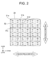
- FIG. 2 is an explanatory chart showing an example of the layout of sub-pixels 31 which constitute the display panel 12 and lens elements 22 which constitute the lens array 21 shown in FIG. 1 .
- the display panel 12 is constituted with a great number of pixels that are arranged in a lattice form.
- a pixel 32 among those is constituted with four sub-pixels 31 a, 31 b, 31 c, and 31d which are arranged in a form of 2 ⁇ 2, and it is a unit pixel when providing stereoscopic display.
- each of the pixels and the sub-pixels is disposed on a square lattice.
- the lens array 21 is constituted with a great number of lens elements that are disposed in a lattice form. Further, each lens element is located at a position and in a size corresponding to each pixel of the display panel 12. Here, the lens element 22 of the lens array 21 is disposed by corresponding to the pixel 32 of the display panel 12.
- H1V1 means a sub-pixel corresponding to the image 1
- H2 means a sub-pixel corresponding to the image 2 respectively.
- V1 means a sub-pixel corresponding to the image 3
- V2 means a sub-pixel corresponding to the image 4, respectively.
- the layout relation of the pixel 32 that is the unit pixel when providing stereoscopic display and the sub-pixels 31 is determined according to the layout of the lenses and the positions as well as the number of the images to be displayed.
- the sub-pixel 31a displays “H1” and "V1". Thus, it is expressed as “H1V1” in FIG. 2 .
- the sub-pixel 31b displays “H2V1”
- the sub-pixel 31c displays “H1V2”
- the sub-pixel 31d displays "H2V2", respectively.
- the density of the sub-pixels for distributing the images in the horizontal direction and the vertical direction is the same, so that the horizontal resolution and the vertical resolution are the same naturally.
- each of the sub-pixels H1V1, H2V1, H1V2, and H2V2 may be monochrome pixels or may be pixels using arbitrary four colors such as RGBW, RGBY, CMYK, CMYW, or the like. Further, the sub-pixels within the pixels may be arranged to be in different color layout between the pixels in such a manner that the existing probabilities of each of the colors become the same for the X-axis and the Y-axis.
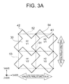
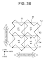
- FIG. 3A and FIG. 3B are explanatory charts showing examples of the aperture shape of the sub-pixel 31 shown in FIG. 2 .
- the above-described horizontal direction (the direction in parallel to the line connecting the left eye and the right eye of the observer) on the display panel 12 is defined as the X-axis
- the direction vertical to the X-axis on the display panel 12 is defined as the Y-axis
- the direction vertical to the display panel 12 is defined as the Z-axis, respectively.
- FIG. 3A is a case where the observer views from the horizontal direction
- FIG. 3B shows a case where the observer views from the vertical direction, respectively.
- the direction vertical to the X-axis is defined as a first lattice line 51
- the direction vertical to the Y-axis is defined as a second lattice line 52.
- the first lattice line 51 and the second lattice line 52 are arranged at equivalent pitches at a pitch corresponding to the resolution of the display device for the X-axis and the Y-axis, respectively.
- the intersection point of the first lattice line 51 and the second lattice line 52 is defined as a square lattice point 54.
- a lattice having four square lattice points 54 disposed at the four corners thereof is a square lattice 53.
- the first non-control region 41 between the sub-pixels is bent with respect to the first lattice line 51, and the second non-control region 42 is also bent with respect to the second lattice line.
- the first non-control region is extended along the first lattice line
- the second non-control region is extended along the second lattice line.
- the point at which the first non-control region 41 and the second non-control region 42 intersect with each other matches the square lattice point 54.
- the boundary line that determines the non-control region between the sub-pixels always goes over the square lattice point, and the aperture shape of the pixel is regulated in such a manner that the boundary is surrounded by a plurality of boundary lines which are bent with respect to the lattice line.
- first lattice line 51, the second lattice line 52, the square lattice 53, and the square lattice point 54 described above are all parameters employed for regulating the shape of the sub-pixel 33, and that those are virtual lines or points within the display panel.
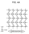
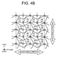
- FIG. 4A and FIG. 4B are explanatory charts showing examples of a case where the intersection part of the non-control regions between the sub-pixels is not on the square lattice point regarding the aperture shape of the sub-pixels shown in FIG. 2 .
- the intersection part of the non-control regions between the sub-pixels does not exist on the square lattice point, there are inconveniences generated in regards to two points, i.e., a point that "the horizontal parallax image is greatly mixed into the vertical parallax image" and a point that "the numerical apertures are not inform for the neighboring sub-pixels".
- the two points are not satisfied with the pixel shape in which the image is simply developed in two directions based on the pixel shape with which the 3D moiré is lightened in one direction as described in the conventional case.
- FIG. 4A shows an example of a case where the intersection part of the non-control regions between each of the sub-pixels is shifted from the square lattice point only for one direction out of the horizontal and vertical directions
- FIG. 4B shows an example of a case where the intersection part is shifted from the square lattice point in both the horizontal and vertical directions.
- FIG. 4B in particular, it is recognized that the horizontal parallax image is greatly mixed into the vertical parallax image. This is because the intersection part of the non-control regions between the sub-pixels is shifted greatly from the square lattice point so that the aperture shape of the sub-pixels cannot correspond to the double directions. This will be described later.
- FIG. 5 is an explanatory chart showing another example of the aperture shape of the sub-pixels shown in FIG. 2 .
- the first non-control region and the second non-control region are both bent twice with respect to one side of a single square lattice.
- the aperture shapes of the sub-pixels in the X-axis and Y-axis directions can all be formed in a similar shape.
- the aperture shapes become substantially the same between the neighboring sub-pixels (e.g., between H1V1 and H2V1, between H1V1 and H1V2), so that an excellent color balance can be achieved between each of the sub-pixels.
- FIG. 3A and FIG. 3B shows an example of a case where the non-control regions between the sub-pixels 34 are bent once regarding both of the first non-control region and the second non-control region.
- the aperture shapes of the sub-pixels are different for the X-axis direction and the Y-axis direction, and the aperture shapes between the neighboring sub-pixels (e.g., between H1V1 and H2V1, between H1V1 and H1V2) are disposed by being rotated by 90 degrees.
- the shape shown in FIG. 5 is advantageous in terms of securing the numerical aperture with high-definition pixels since the required number of bending is "1" and, at the same time, it is also advantageous in terms of the stereoscopic display property as will be described later.
- Other technical significances are the same as those of the shape of the sub-pixel 33.
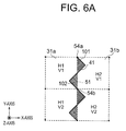
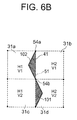
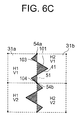
- FIG. 6A to FIG. 6C are explanatory charts showing more details of the aperture shape of the sub-pixel 33 or 34 shown in FIG. 3 and FIG. 5 .
- FIG. 6 only a part of the aperture shape is emphasized and illustrated for simplifying the drawings.
- FIG. 6A to FIG. 6C show each of examples of the cases where the shape of the triangles formed according to the bent number of the first non-control region 41 and the number of the triangles per sub-pixel are different.
- FIG. 6A shows a case where the first non-control region 41 is bent twice for the length of one side of the square lattice of the first lattice line.
- FIG. 6B shows a case where the first non-control region 41 is bent once for the length of one side of the square lattice of the first lattice line.
- FIG. 6C shows a case where the first non-control region 41 is bent three times for the length of one side of the square lattice of the first lattice line.
- a right-side triangle 101 and a left-side triangle 102 are formed by the first lattice line 51 and the first non-control region 41.
- +X-axis direction with respect to the lattice line 51 is defined as "right side”
- -X-axis direction is defined as "left side”.
- the right-side triangle 101 contributes to the aperture of the sub-pixel 31a
- the left-side triangle contributes to the aperture of the sub-pixel 31b.
- the square lattice points are arranged at equivalent pitch and the areas of each of the square lattices corresponding to each of the sub-pixels are the same.
- the aperture areas of the sub-pixels 31a and 31b can be made equivalent through equalizing the areas of the right-side triangle 101 and the left-side triangle 102.
- the degrees of the mixture of the images of the neighboring pixels are about the same, so that a fine stereoscopic display property can be achieved.
- the sub-pixels 33 and 34 shown in FIGS. 3 , 5 , and 6 are the cases where the non-control region is bent twice or once for all the four sides of the square lattice corresponding to the sub-pixel. However, it is not specifically essential to bend all of the four sides for the same number of times and at the same bent angles. The same effects can be acquired as the stereoscopic display property, as long as the areas of each of the polygons are equal.
- the structural modes of the non-control regions between the neighboring sub-pixels vary depending on the type of the display panel.
- examples of the non-control regions may be a black matrix and signal wirings in an LCD, partition walls and signal wirings in an organic EL, partition walls and the like in a PDP. In general, those are formed in the width in the order of several ⁇ m to several tens of ⁇ m.
- FIG. 2 uses a fly-eye lens as the optical module.
- the fly-eye lenses are arranged in matrix by corresponding to each of the pixels and in parallel, respectively, to the X-axis and the Y-axis that is orthogonal to the X-axis to have the horizontal parallax and the vertical parallax with respect to the X-axis.
- a parallax barrier or a pinhole barrier which shield light rays of undesired directions.
- a lens having distributed refractive indexes such as a GRIN lens using liquid crystal as a light-ray control module.
- the module which does not separate the light rays in the two directions simultaneously but separates the light rays in one direction at a time e.g., the light rays are not separated in the Y-axis direction when the light rays are separated in the X-axis direction or the light rays are not separated in the X-axis direction when the light rays are separated in the Y-axis direction.
- switching of a stereoscopic image display mode where the light rays are separated only in the first direction or the second direction and a bidirectional stereoscopic image display mode where the light rays are separated in the first and second directions simultaneously can be done by electric controls of the lens array.
- the parallax barrier or the GRIN lens constituted with an active element using liquid crystal or the like it is possible to select the two-direction simultaneous light ray separation and one-direction-only light ray separation.
- the light rays may be separated through performing controls of the active elements by corresponding to the directions of the horizontal parallax in each of the cases where the stereoscopic image display device is observed in a normal direction and where the device is rotated by 90 degrees.
- the light rays are separated only in the horizontal direction that is the X-axis direction.
- the first image and the second image are the same and the image 3 and the image 4 are the same, the light rays are separated only in the vertical direction that is the Y-axis direction.
- the two parallax directions are generally determined by the normal usages of the image display device. For example, cases of changing the directions of the devices at the time of use and changing the display directions according to the application and contents in mobile phones (smartphones and feature phones), tablet terminals, game machines, and monitor displays (of personal computers and the like) correspond to that. It is sufficient to secure the directions where the observer can recognize the stereoscopic display, so that the two parallax directions do not necessarily need to be in a strictly orthogonal relation with each other.
- FIG. 7 is an explanatory chart showing the bent angles and shapes of non-control regions 71 a to 71 f of the sub-pixel 33 or 34 shown in FIGS. 3 , 5 , and 6 , and observed images 81a to 81c visually recognized by the observer at each of those.
- the widths of the non-control regions 71a to 71c are substantially set as constant.
- FIG. 7A shows a case where the bent angle ⁇ a is about 6 degrees
- FIG. 7B shows a case where the bent angle ⁇ b is about 25 degrees
- FIG. 7C shows a case where the bent angle ⁇ c is about 45 degrees, respectively.
- FIG. 7D and thereafter will be described later.
- the non-control region 71 a exists between neighboring sub-pixels 61a and 62b shown in FIG. 7A .
- the bend angle ⁇ of the non-control region 71a is almost close to 0 degree, so that there is a dark part formed due to the non-control region for the X-axis direction that is the parallax direction. This dark part is displayed by being expanded by the optical module, and visually recognized by the observer as the 3D moiré shown in the observed image 81 a.
- FIG. 7D shows the shape of the non-control region (upper side) and the observed image visually recognized by the observer at each point (lower side) in a case where there are two values for the width of the non-control region (a first example)
- FIG. 7G shows the same in a case where the width of the non-control region changes continuously (a second example)
- FIG. 7H shows the same in a case where the width of the non-control region changes discontinuously (a third example).
- FIG. 7D , 7G , and 7H a graph showing the width of the Y-axis component of the non-control region with respect to the X-axis position is shown by being superimposed on the observed image.
- FIG. 7E and FIG. 7F show the effects acquired by the first example shown in FIG. 7D .
- the first example shown in FIG. 7D is an example of the case where there are two values for the width of the non-control region.
- the width of the non-control region at an arbitrary point on the center line L1d of the non-control region is determined according to the length of the shortest line that passes through an arbitrary point on L1d and two points on the neighboring sub-pixel boundary.
- the widths of the non-control region at the unit lattice points Q1d and Q2d are defined as two values of W1d and W3d, respectively.
- the width of the non-control region is set constant as W1d from the unit lattice point Q1d on the center line L1d towards the direction of the bent point P1.
- the width of the non-control region continuously changes from a point J in the vicinity of the bent point P1d and changes to W2d at the bent point P1d.
- the width of the non-control region also changes continuously from P1d to a point K.
- the width of the non-control region is set as constant at W3d from the point K to the direction of the unit lattice point Q2d.
- the X-axis range of the width of the non-control region in the vicinity of the bent point P1d is Px1 and the X-axis range of the aperture part is Px2 in the shape of such non-control region
- the value of the width of the Y-axis component of the non-control region with respect to the X-axis direction continuously changes within Px1 and it is fixed to a constant value within Px2.
- the 3D moiré observed by the observer is a change in the dark part in the parallax direction generated by the non-control region.
- the parallax direction and the X-axis direction are substantially in parallel, the change in the dark part in the X-axis direction becomes a continuous change due to the shape. That is, this makes it possible to improve the display quality.
- FIG. 7E shows charts regarding electric fields generated in a case where the width of the non-control region is substantially set as constant at W1d1 and a case of the first example shown in FIG. 7D , which show the expanded shapes of the end parts of a pixel electrode 1 and a pixel electrode 2.
- the end part of the pixel electrode 1 and the end part of the pixel electrode 2 are disposed as the boundary of the neighboring pixels, a narrow part exists in a part of the pixel electrode 2, and FIG. 7E show enlarged views of that narrow part.
- FIG. 7E shows the electric fields in model charts of electric force lines (dotted-line arrows).
- the potential fluctuation can be eased while keeping the numerical aperture almost constant so that the display inferior can be lightened through setting the distance between the pixel electrode 1 and the pixel electrode 2 in the narrow end part to be wide, i.e., through setting the width of the non-control region in the narrow end part as W2d1 (>W1d1).
- the display inferior can be covered by the black matrix or the signal wiring through setting the width of the black matrix or the signal wiring in the narrow end part to be wide while keeping the pixel electrodes as they are, i.e., through setting the width of the non-control region in the narrow end part as W3d1 (>W1d1). In both cases, useful effects for improving the display quality can be achieved.
- FIG. 7F shows charts regarding the pattern shift of the color layers in the case where the width of the non-control region is substantially set as constant at W1d1 and a case of the first example shown in FIG. 7D .
- the upper half parts show the enlarged shapes of the pixel electrode 1 and the pixel electrode 2.
- the end part of a color layer 1 and the end part of a color layer 2 are disposed as the boundary of the neighboring pixels, a narrow part exists in a part of the color layer 2, and
- FIG. 7F shows enlarged views of that narrow part.
- the lower parts show sectional views of the case where the width of the non-control region is set as substantially constant and the case of the first example, respectively.
- a signal wiring or a black matrix is formed, for example.
- the width W1d1 of the non-control region is substantially constant, there is a tendency that the pattern shift of the color layers becomes large compared to other areas as shown on the lower left side of FIG. 7F . This brings up such an issue that failures such as color mixture tend to be generated in the narrow end part because the pattern shift influences the other neighboring color layer.
- the second example shown in FIG. 7G is an example of the case where the width of the non-control region changes continuously. It is the feature of the second example that the width W1e of the non-control region at the unit lattice point Q1e to the width W2e at the bent point P1e continuously changes from the unit lattice point Q1e towards the direction of the bent point P1e on the center line L1e of the non-control region and, similarly, the width continuously changes from the width W2e at the bent point P1e to the width W3e at the unit lattice point Q2e from the bent point P1e towards the direction of the unit lattice point Q2e on the center line L1e of the non-control region.
- the X-axis range of the width of the non-control region in the vicinity of the bent point P1d is Px1 and the X-axis range of the aperture part is Px2 in the shape of such non-control region
- the value of the width of the Y-axis component of the non-control region with respect to the X-axis direction monotonously increases within Px1 and monotonously decreases within Px2.
- the change in the dark part in the X-axis direction becomes a continuous change due to the shape. Therefore, it is possible to ease the 3D moiré.
- the width of the non-control region can be changed continuously with respect to the center line.
- the third example shown in FIG. 7H is an example of the case where the width of the non-control region changes discontinuously. It is the feature of the third example that there are two values W1f and W2f as the width of the non-control region between the bent part P1f and the unit lattice point Q2f on the center line L1f, and the change in the width is discontinuous.
- the non-control region is bent so that the value of the width of the Y-axis component of the non-control region for the X-axis direction becomes a continuous change or takes a constant value. Therefore, as in the cases of the first example and the second example described above, the change in the dark part in the X-axis direction becomes a continuous change, so that the 3D moiré can be eased.
- the width of the non-control region with respect to the center line can be changed discontinuously from the unit lattice point to the bent point.
- an irregular design such as disposing a switching device or a contact hole on a signal wiring.
- All of the first to third examples described by referring to FIGS. 7D , 7G , and 7H show the cases where the non-control region is bent once. However, those examples can be applied to cases where the non-control region is bent twice or more, and the same effects can be acquired with those cases. More specifically, those examples can be applied to the cases where the number of bending is "2" or more through replacing the unit lattice point Q with the bent part P.
- FIG. 8 is an explanatory chart showing the shape of a non-control region 72 in the aperture shape where the intersection part of the non-control region between the sub-pixels shown in FIG. 4 does not exist on the square lattice point, and an observed image 82 that is visually recognized by the observer.
- the non-control region 72 is not bent, not disposed on the square lattice point, and disposed obliquely with respect to the Y-axis, it is also possible to lighten the 3D moiré for the X-axis direction.
- the 3D moiré for both of the X-axis direction and the Y-axis direction cannot be lightened as described in FIG. 4A and FIG. 4B .
- the 3D moiré can be lightened or prevented simultaneously for the two parallax directions.
- FIG. 9 shows graphs regarding the relations between the bent angles of the non-control regions 71 a to 71c of the sub-pixel 33 or 34 shown in FIGS. 3 and 5 and the stereoscopic display property.
- FIG. 9A shows a case of the sub-pixel 33 that is bent twice as shown in FIG. 3
- FIG. 9B shows a case of the sub-pixel 34 that is bent once as shown in FIG. 5 , respectively.
- the 3D moiré and the 3D crosstalk are shown as the stereoscopic display property.
- the 3D moiré is a luminance fluctuation for the viewing angles shown in FIG. 8 , and the subjective influence thereof is determined according to the extent of the luminance fluctuation and the angle at which the fluctuation occurs.
- the 3D crosstalk shows the proportion of the left-eye image (L image) mixed into the right-eye image (R image) or, inversely, the proportion of the R image mixed into the L image. When this value becomes large, it becomes difficult to provide stereopsis.
- the practical upper limit values determined based on the actual optical property and the result of subjective evaluation are shown as a level 1 and a level 2.
- the level 1 shows a permissible property level
- the level 2 shows a desirable property level.
- the lattice pitches are set as "8", "14", and "20" when the width of the non-control region is set as "1" (the lattice pitches are considered as the standardized lattice pitches hereinafter).
- the stereoscopic display property becomes changed as well.
- the 3D moiré the relative non-control region for the lattice pitch is expanded.
- the 3D moiré is deteriorated as the standardized lattice pitch becomes smaller at the same bent angle.
- the 3D crosstalk the mixed area of the neighboring sub-pixel becomes smaller when the relative non-control region for the lattice pitch becomes expanded.
- the 3D crosstalk is improved as the standardized lattice pitch becomes smaller at the same bent angle.
- FIG. 9A through comparing FIG. 9A with FIG. 9B , it can be seen that the change in the stereoscopic display property with respect to the change in the standardized lattice pitch largely depends on the number of bending.
- the bent angle is desired to be within the range of 38 to 82 degrees for the level 1, and desired to be within the range of 55 to 80 degrees for the level 2.
- the range of the bent angle is widened further.
- the range of 22 to 82 degrees is the preferable range for the level 1
- the range of 28 to 80 degrees is the preferable range for the level 2. That is, with the sub-pixel shape that is bent twice, it can be seen that there is a large difference between the bent angle ranges that can be employed for the standardized lattice pitches 8 and 14.
- the bent angle is desired to be within the range of 18 to 62 degrees for the level 1, and desired to be within the range of 24 to 53 degrees for the level 2.
- the range of the bent angle is widened further.
- the range of 10 to 62 degrees is the preferable range for the level 1
- the range of 13 to 53 degrees is the preferable range for the level 2.
- the difference between the bent angle ranges of the standardized lattice pitches 8 and 14 is smaller with the shape of the sub-pixel 34 that is bent once compared to the case of FIG. 9A .
- the bent angle range is smaller in the case of FIG. 9B . That is, in a case where the standardized lattice pitch is small, i.e., in a case of high definition, the case of FIG. 3 with bending of twice is desirable than the case of FIG. 4 with bending of once. This is the same as the explanation provided by referring to FIG. 5 .
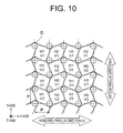
- the square lattice point can be considered as a square lattice circle depending on the size of the square lattice.
- the reason that the intersection part of the non-control regions between the sub-pixels need to exist on the square lattice is "to secure the uniformity of the numerical apertures between the neighboring sub-pixels" as described above.
- the value of the radius the square lattice circle in that case is derived from the permissibility of the fluctuation of the numerical apertures between the neighboring sub-pixels.
- FIG. 10 is an explanatory chart showing an example of a case where the intersection parts of the first non-control regions and the second non-control regions are disposed on the square lattice circles with the diameter D in the sub-pixel 33 or 34 shown in FIGS. 3 , 5 , and 6 .
- the value of the diameter D of the square lattice circle becomes larger with respect to the length P of one side of the square lattice, the fluctuation in the numerical apertures between the neighboring sub-pixels becomes larger.
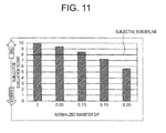
- FIG. 11 is a graph showing the subjective evaluation of the display property levels in the color shift caused due to the nonuniformity in the luminance of each color with respect to the extent of the normalized diameter D/P in a case where the intersection parts of the first non-control regions and the second non-control regions shown in FIG. 10 are disposed on the square lattice circles of the diameter D.
- P is the pitch of the square lattices at which the sub-pixels 33 or 34 are disposed.
- the sub-pixels within the pixels are arranged to be in different color layout between each of the pixels so that the existence probabilities of each color become the same for the X-axis and the Y-axis.
- the size of the normalized diameter D/P of the square lattice circle is 0.1 or smaller.
- the nonuniformity for the color visual field angle becomes actualized according to deterioration in the uniformity of the aperture areas of each of the sub-pixels, thereby deteriorating the display quality greatly as the color shift. Therefore, it is desirable to set the diameter D of the square lattice circle as 0.1 or smaller with respect to the square lattice pitch P.
- the stereoscopic image display device 10 can prevent the horizontal parallax image from being largely mixed into the vertical parallax image and secure the uniformity of the numerical apertures between the neighboring sub-pixels when the first direction is taken as the horizontal direction and the second direction is taken as the vertical direction. Therefore, it is possible to suppress both the 3D moiré and the 3D crosstalk. Further, it is possible to acquire the same 3D resolution for the horizontal direction and the vertical direction, so that the same stereoscopic display property can be acquired through rotating the display device by 90 degrees.
- the stereoscopic image display device 10 is suitable for those capable of changing the display direction according to the facing direction of the device when in use and according to the application and contents in mobile phones (smart phones and feature phones), tablet terminals, game machines, and monitor displays (of personal computers and the like).
- the present invention is structured to properly distribute the light emitted for a plurality of directions with the optical modules. This makes it possible to provide the stereoscopic image display device which exhibits such an excellent characteristic that it is capable providing fine stereopsis by suppressing generation of the 3D moiré and influence of the 3D crosstalk even when observed from any of a plurality of directions.
- a stereoscopic image display device 110 is structured to dispose each of the sub-pixels, which is disposed on the square lattice in the first exemplary embodiment, on a rectangular lattice or a rhombic lattice.
- the same effects as those of the first exemplary embodiment can be acquired even with the stereoscopic image display device constituted with the pixels disposed on the rectangular lattice or the rhombic lattice.
- FIG. 12 is an explanatory chart showing the structure of the stereoscopic image display device 110 according to the second exemplary embodiment of the present invention.
- the stereoscopic image display device 110 includes a display panel 112 to be described later and a lens array 121 that is an optical module disposed on the front face of the display panel 112.
- the structures of the display panel 112 and the lens array 121 are equivalent to those of the first exemplary embodiment, but shapes of each of those are different from those of the first exemplary embodiment.
- the display panel 112 in this exemplary embodiment is structured by disposing each of the sub-pixels on the rectangular lattice or the rhombic lattice, while each of the sub-pixels is disposed on the square lattice in the first exemplary embodiment.
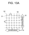
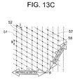
- FIG. 13 shows explanatory charts regarding the external appearances of the square lattice, the rectangular lattice, and the rhombic lattice where each of the sub-pixels is disposed on the display panel 112 shown in FIG. 12 .
- FIG. 13A shows a square lattice 53
- FIG. 13B shows a rectangular lattice 55
- FIG. 13C shows a rhombic lattice 57, respectively.
- first lattice lines 51 in the direction vertical to the first parallax direction and second lattice lines 52 in the direction vertical to the second parallax direction are shown. Further, the first lattice lines 51 are arranged at an equivalent pitch at a pitch j for the first parallax direction, and the second lattice lines 52 are arranged at an equivalent pitch at a pitch k for the second parallax direction.
- the pitch j and the pitch k are determined by corresponding to the resolution of the display panel. The resolution is the number of pixels per unit length, and j and k in FIG. 13 are the sub-pixel pitches.
- the relation between the number of pixels and the number of sub-pixels is determined uniquely according to the display type of the display.
- the pitch includes the sub-pixel pitch or the pixel pitch.
- the intersection point between the first lattice line 51 and the second lattice line 52 is a square lattice point 54 in FIG. 13A , a rectangular lattice point 56 in FIG. 13B , and a rhombic lattice point 58 in FIG. 13C .
- FIG. 14 is a table showing each content of the square lattice 53, the rectangular lattice 55, and the rhombic lattice 58 shown in FIG. 13A to FIG. 13C .
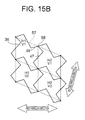
- FIG. 15 shows explanatory charts regarding sub-pixels 35 and 36 to which the rectangular lattice 55 and the rhombic lattice 57 shown in FIG. 13B to FIG. 13C are employed.
- FIG. 15A shows the sub-pixel 35 to which the rectangular lattice 55 is employed.
- FIG. 15B shows the sub-pixel 36 to which the rhombic lattice 57 is employed.
- the shapes of both of the sub-pixels 35 and 36 are the same as those of the first exemplary embodiment.
- FIG.14A and FIG. 14B both show the shape of "twice-bending". However, this shape may naturally be changed to the shape of "once-bending" described already in the first exemplary embodiment or other shapes.
- FIG. 16 is an explanatory chart showing an example of the layout of sub-pixels 35 to which the rectangular lattice 55 shown in FIG. 13B and FIG. 15A is employed and the lens array 121.
- the display panel 112 is constituted with a great number of vertical-stripe form pixels 37 that are arranged in a rectangular lattice form.
- the pixel 37 is constituted with four sub-pixels 37a, 37b, 37c, and 37d (same as the sub-pixel 35 shown in FIG. 15A ) which are arranged in a form of 2 ⁇ 2.
- the lens array 121 is constituted with a great number of lens elements that are disposed in a lattice form. Further, each lens element is located at a position and in a size corresponding to each pixel of the display panel 112. Here, a lens element 122 of the lens array 121 is disposed by corresponding to a pixel 132 of the display panel 112.
- the structures of the pixel 132 and the lens element 122 conform to those of the first exemplary embodiment shown in FIG. 2 , respectively. However, the pixel 132 and the lens element 122 are both formed in a rectangular shape.
- the layout is the same as a typical pixel group in which colors are arranged in a vertical-stripe layout.
- a stereoscopic image display device 210 includes first and second non-control regions which are different from those of the first exemplary embodiment. That is, it is structured in such a manner that: one of the first and second non-control regions is bent once in two unit lattices formed by lattice lines that are segments disposed vertically and at an equivalent pitch for the first direction and the second direction, respectively; the other one of the first and the second non-control regions is bent at least once within the unit lattice; and the intersection part of the first and the second non-control regions does not exist on two points out of the four lattice points of the unit lattice.
- FIG. 17 is an explanatory chart showing the structure of the stereoscopic image display device 210 according to the third exemplary embodiment of the present invention.
- the stereoscopic image display device 210 includes a display panel 212 to be described later and the lens array 21 same as that of the first exemplary embodiment which is an optical module disposed on the front face of the display panel 212.
- the structure of the display panel 212 is equivalent to those of the first and second exemplary embodiments, but shape thereof is different from that of the first exemplary embodiment.
- the display panel 212 is structured by disposing each of the sub-pixels on the square lattice as in the case of the first exemplary embodiment.
- the first non-control region and the second non-control region are bent at least once within the unit lattice and all the intersection parts are in the structure where the non-control regions exist on the square lattice points (or the rectangular lattice points or the rhombic lattice points) in the first and second exemplary embodiments
- the third exemplary embodiment employs the structure in which either the first non-control region or the second non-control region is bent once within the unit lattice and the other non-control region is bent at least once within the unit lattice.
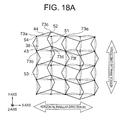
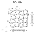
- FIG. 18A is an explanatory chart showing the layout of each of the sub-pixels 38 on the display panel 212 shown in FIG. 17 .
- FIG. 18B is an explanatory chart showing the layout of a case where XY-axes of the sub-pixels 38 shown in FIG. 18A are rotated counterclockwise by 90 degrees with respect to the Z-axis.
- a first non-control region 43 is bent once for a single square lattice, and a second non-control region 44 is bent once for two square lattices.
- intersection parts 73a and 73b are disposed on the square lattice points
- intersection parts 73c and 73d are not disposed on the square lattice points
- intersection parts 73e and 73f are disposed on the square lattice points.
- the intersection parts not disposed on the square lattice points exist in two periods of the first lattice line for the X-axis on the second square lattice lines including the intersection parts 73a, 73c, and 73e.
- intersection parts are disposed on the square lattice points on the first lattice lines including the intersection parts 73a and 73b. In the meantime, none of the intersection parts is disposed on the square lattice points on the first lattice lines including the intersection parts 73c and 73d.
- a method for checking whether or not actually the intersection part of the first and second non-control regions exists on the lattice point or the lattice circle is as follows. First, the intersection parts of the first and the second non-control regions are plotted. Then, the first and second lattice lines that are vertical segments for the first and second directions for separating the light rays are drawn by including the plotted points, and the lattice points at which the lattice lines intersect and the unit lattice are acquired. When there are two points where the lattice points and the intersection parts overlapped with each other within the unit lattice, it is confirmed that the structure of the present invention is employed. Further, the lattice point may be within the diameter range of 0.1 with respect to the length of one side of the unit lattice.
- a stereoscopic image display device 310 according to a fourth exemplary embodiment of the present invention is acquired by further expanding the first exemplary embodiment, in which a pixel is constituted with M ⁇ N pieces of sub-pixels when the number of viewpoints in the first direction is defined as N and the number of viewpoints in the second direction is M (M and N are integers of 2 or larger).
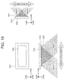
- FIG. 19 is an explanatory chart showing the structure of the stereoscopic image display device 310 according to the fourth exemplary embodiment of the present invention.
- the stereoscopic image display device 310 includes a display panel 312 to be described later and a lens array 321 that is an optical module disposed on the front face of the display panel 312.
- the structures of the display panel 312 and the lens array 321 are equivalent to those of the first exemplary embodiment, but shapes of each of those are different from those of the first exemplary embodiment.
- the display panel 312 in this exemplary embodiment is structured with pixels each constituted with 4 ⁇ 4 sub-pixels, while each pixel disposed on the square lattice is constituted with 2 ⁇ 2 sub-pixels in the first exemplary embodiment. This will be described hereinafter.
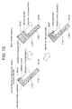
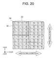
- FIG. 20 is an explanatory chart showing an example of the layout of pixels 332 which constitute the display panel 312 and lens elements 322 which constitute the lens array 321 shown in FIG. 19 .
- the pixel 332 is constituted with sixteen sub-pixels 331a to 331p which are arranged in a form of 4 ⁇ 4.
- the lens array 321 is constituted by disposing a great number of lens elements 322 in a lattice form.
- each lens element is located at a position and in a size corresponding to each pixel of the display panel 312.
- the lens element 322 of the lens array 321 is disposed by corresponding to the pixel 332 of the display panel 312. This is the unit pixel at the time of stereoscopic display.
- the sub-pixel corresponding to the image 1 in the horizontal direction is expressed as "H1”
- the sub-pixel corresponding to the image 2 is expressed as “H2”
- the sub-pixel corresponding to the image 3 is expressed as “H3”
- the sub-pixel corresponding to the image 4 is expressed as "H4".
- the sub-pixel corresponding to the image 5 is expressed as "V1”
- the sub-pixel corresponding to the image 6 is expressed as "V2”
- the sub-pixel corresponding to the image 7 is expressed as "V3”
- the sub-pixel corresponding to the image 8 is expressed as "V4".
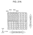
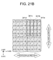
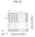
- FIGS. 21A to 21C are explanatory charts showing display examples when displaying stereoscopic images for the multi-viewpoints specifically by the stereoscopic image display device 310 shown in FIG. 19 to FIG. 20 .
- FIGS. 21A and 21B show light ray separation only in one direction out of the horizontal and vertical directions
- FIG. 21C shows a display example of light ray separation for both the horizontal and vertical directions.
- a fly-eye lens is illustrated to be used as a unit lens constituting the lens element 322.
- a parallax barrier or a GRIN lens by an active element using liquid crystal or the like it is possible to select light separation in two directions simultaneously or light ray separation only in one direction. Thus, those are preferable for a case where controls of FIGS. 21A to 21C is executed by the same structure.
- FIG. 21A shows a case of achieving stereopsis of four viewpoints in the horizontal direction by using each of four-viewpoint images (first to fourth images) having parallax only in the horizontal direction, in which signals corresponding to the first image are inputted to a sub-pixel group 340a (sub-pixels 331a, e, i, m), signals corresponding to the second image are inputted to a sub-pixel group 340b (sub-pixels 331b, f, j, n), signals corresponding to the third image are inputted to a sub-pixel group 340c (sub-pixels 331c, g, k, o), signals corresponding to the fourth image are inputted to a sub-pixel group 340d (sub-pixels 331d, h, 1, p), and light ray separation is performed only in the horizontal direction of the X-axis.
- signals corresponding to the first image are inputted to a sub-pixel group 340a (sub-pixels 331a, e
- FIG. 21B shows a form which is acquired by rotating FIG. 21A by 90 degrees in a clockwise direction.
- Signals corresponding to the first image are inputted to a sub-pixel group 341a (sub-pixels 331a, b, c, d)
- signals corresponding to the second image are inputted to a sub-pixel group 341b (sub-pixels 331e, f, g, h)
- signals corresponding to the third image are inputted to a sub-pixel group 341 c (sub-pixels 331i, j, k, l)
- signals corresponding to the fourth image are inputted to a sub-pixel group 341d (sub-pixels 331m, n, o, p), and light ray separation is performed only in the horizontal direction of the Y-axis to achieve stereopsis of four viewpoints in the horizontal direction.
- FIG. 21C shows a case of achieving stereopsis of two viewpoints each in the horizontal direction and the vertical direction by using each of four-viewpoint images (fifth to eighth images) having parallax in the horizontal direction and the vertical direction, in which signals corresponding to the fifth image are inputted to a sub-pixel group 342a (sub-pixels 331a, b, e, f), signals corresponding to the sixth image are inputted to a sub-pixel group 342b (sub-pixels 331c, d, g, h), signals corresponding to the seventh image are inputted to a sub-pixel group 342c (sub-pixels 331i j, m, n), signals corresponding to the eighth image are inputted to a sub-pixel group 342d (sub-pixels 331k, l, o, p), and light ray separation is performed in the horizontal direction of the X-axis and the vertical direction of the Y-axis.
- signals corresponding to the fifth image are inputted
- FIG. 22 is an explanatory chart showing an example of color layout for each of the sub-pixels 331 on the stereoscopic image display device shown in FIG. 19 to FIG. 20 .
- four primary colors of RGBW are arranged for each of the sub-pixels 331.
- it is also possible to arrange arbitrary four colors such as RGBY, CMYK, or CMYW.
- FIGS. 20A to 20C it is possible to constitute each of the sub-pixel groups 341 with the four colors of RGBW at all times.
- a light-shielding pattern existing within the aperture part of the sub-pixel excluding the first and the second non-control regions is formed with segments in parallel to the first and second non-control regions.
- the light-shielding pattern is a signal line, a switching element, a contact hole, or a source electrode.
- the non-control region is constituted with a signal line, a partition wall, or a black matrix.
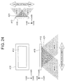
- FIG. 24 is an explanatory chart showing the structure of the stereoscopic image display device 410 according to the fifth exemplary embodiment of the present invention.
- the stereoscopic image display device 410 includes a display panel 412 to be described later and a lens array 421 that is an optical module disposed on the front face of the display panel 412.
- the structures of the display panel 412 and the lens array 421 are equivalent to those of the first exemplary embodiment.
- the emission pattern of the sub-pixel i.e., the aperture part
- the region other than the first and second non-control regions described above This depends on the type of the electro-optic element of the display panel.
- a reflection type LCD, an electrophoretic element, or a top emission type organic EL is not so susceptible to the influence of the switching element and the signal wiring.
- the above-described concept as it is can be simply applied thereto, and there is no specific problem raised when paying attention only to the patterns of the first and second non-control regions.
- the fifth exemplary embodiment is designed to make it possible to apply the same concept as those of the first to fourth exemplary embodiments described above in the case described above not only for the patterns of the first and second non-control regions but also for the switching element and the signal wiring. This will be described hereinafter.
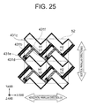
- FIG. 25 is an explanatory chart showing a structural example of the switching element and the signal wiring in a sub-pixel 431 which constitutes the display panel 412 shown in FIG. 24 .
- a source electrode 431b and a data signal line 431c are connected via a switching element 431a.
- a storage 431f is formed through capacitively coupling a storage wiring 431e and the source electrode 431b via an insulating film.
- the storage wiring 431 e does not correspond to the first and second non-control regions described above.
- switching element 431a and the source electrode 431b it is desirable to form those substantially in parallel to the data signal line 431c or the gate signal line 431d.
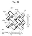
- FIG. 26 is an explanatory chart showing another structural example of the switching element and the signal wiring in the sub-pixel 431 which constitutes the display panel 412 shown in FIG. 24 .
- the source electrode 431b is connected to the a pixel electrode 431h via a contact hole 431 g.
- the 3D moiré that is the object to be overcome with the exemplary embodiments is not limited only to the stereoscopic image display device.
- the 3D moiré may be generated in a display device which displays different images for a plurality of observing positions by using an optical module that gives the directivity to the light rays, such as a car navigation device which displays different images for the driver seat and the passenger seat, respectively. It is also possible to suppress the 3D moiré by employing the techniques of the exemplary embodiments for such display device.
- a stereoscopic image display device capable of providing bidirectional stereoscopic image display which displays parallax images for at least two viewpoints each simultaneously for a first direction and a second direction and unidirectional stereoscopic image display which displays parallax images for at least two viewpoints each for either the first direction or the second direction, the stereoscopic image display device including:
- the stereoscopic image display device as depicted in Supplementary Note 1 or 2, wherein the first direction and the second direction are orthogonal to each other.
- the stereoscopic image display device as depicted in Supplementary Note 1, wherein numbers of bending in the first and second non-control regions within the unit lattice with respect to the lattice line are same.
- the stereoscopic image display device as depicted in Supplementary Note 1, 3, or 4, wherein the number of bending is "1", and an angle formed between bent parts of the first and second non-control regions and the lattice line is 18 to 62 degrees.
- the stereoscopic image display device as depicted in Supplementary Note 1, 3, or 4, wherein the number of bending is "2", and an angle formed between bent parts of the first and second non-control regions and the lattice line is 38 to 82 degrees.
- the stereoscopic image display device as depicted in any one of Supplementary Notes 1 to 6, wherein in a case where a direction in parallel to a line connecting a left eye and a right eye of an observer is defined as a horizontal direction, a direction from the left eye to the right eye is defined as a positive direction, the second direction is aligned with the horizontal direction, a plurality of points of bending are provided on both sides of the lattice line with respect to the lattice line that is orthogonal to the horizontal direction, and the positive direction is defined as a right side while a negative direction is defined as a left side, an area of a first polygon formed on the right side and an area of a second polygon formed on the left side between the lattice line and the first non-control region are equivalent.
- the stereoscopic image display device as depicted in any one of Supplementary Notes 1 to 6, wherein in a case where a direction in parallel to a line connecting a left eye and a right eye of an observer is defined as a horizontal direction, a direction from the left eye to the right eye is defined as a positive direction, the second direction is aligned with the horizontal direction, a plurality of points of bending are provided on both sides of the lattice line with respect to the lattice line in the second direction that is the horizontal direction, and the positive direction is defined as an upper side while a negative direction is defined as a lower side, an area of a first polygon formed on the upper side and an area of a second polygon formed on the lower side between the lattice line and the second non-control region are equivalent.
- the stereoscopic image display device as depicted in any one of Supplementary Notes 1 to 6, wherein in a case where a direction in parallel to a line connecting a left eye and a right eye of an observer is defined as a horizontal direction, a direction from the left eye to the right eye is defined as a positive direction, the second direction is aligned with the horizontal direction, and the positive direction is defined as a right side while a negative direction is defined as a left side with respect to the lattice line that is orthogonal to the horizontal direction, an area of a first polygon formed on the right side and an area of a second polygon formed on the left side between the lattice line orthogonal to the horizontal direction and the first non-control region, and an area of a third polygon formed on an upper side and an area of a fourth polygon formed on a lower side between the lattice line in parallel to the horizontal direction and the second non-control region, are all equivalent.
- each of the polygons formed between the lattice line orthogonal to the horizontal direction and the first non-control region or between the lattice line in parallel to the horizontal direction and the second non-control region is a triangle.
- the stereoscopic image display device as depicted in any one of Supplementary Notes 1 to 10, wherein in a case where length of the lattice line within the unit lattice is defined as P, diameter of a lattice circle formed by having the lattice point as a center is defined as D, and a normalized diameter is defined as D/P, the intersection part of the first and the second non-control regions is disposed within the lattice circle with the normalized diameter of 0.1 or smaller.
- the stereoscopic image display device as depicted in any one of Supplementary Notes 1 to 11, wherein in a case where number of viewpoints in the first direction is defined as N and number of viewpoints in the second direction is defined as M (N and M are both integers of 2 or larger), the pixel is constituted with N ⁇ M pieces of sub-pixels.
- the stereoscopic image display device as depicted in any one of Supplementary Notes 1 to 12, wherein width of the first non-control region or the second non-control region changes continuously by corresponding to positions in the second direction or the first direction of the non-control region.
- the stereoscopic image display device as depicted in any one of Supplementary Notes 1 to 12, wherein width of the first non-control region or the second non-control region changes discontinuously by corresponding to positions in the second direction or the first direction of the non-control region between a first bent part or a unit lattice point and a second bent point neighboring to the first bent point or the unit lattice point in the first direction or the second direction of the first non-control region or the second non-control region.
- the stereoscopic image display device as depicted in any one of Supplementary Notes 1 to 16, wherein a light-shield pattern existing within the aperture part of the sub-pixel is formed with segments in parallel to the first and the second non-control regions.
- the stereoscopic image display device as depicted in Supplementary Note 17, wherein the light-shield pattern is a signal line, a switching element, a contact hole, or a source electrode.
- the stereoscopic image display device as depicted in any one of Supplementary Notes 1 to 18, wherein the non-control region is constituted with a signal line, a partition wall, or a black matrix.
- the present invention can be used widely for a display device that displays images capable of providing stereopsis or for a display device that displays different images for a plurality of observing positions, which are used in a television set, a personal computer, a smartphone, a tablet, a game machine, a car navigation device, and the like.
Landscapes
- Engineering & Computer Science (AREA)
- Multimedia (AREA)
- Signal Processing (AREA)
- Physics & Mathematics (AREA)
- General Physics & Mathematics (AREA)
- Optics & Photonics (AREA)
- Testing, Inspecting, Measuring Of Stereoscopic Televisions And Televisions (AREA)
- Stereoscopic And Panoramic Photography (AREA)
Applications Claiming Priority (2)
| Application Number | Priority Date | Filing Date | Title |
|---|---|---|---|
| JP2013037249 | 2013-02-27 | ||
| JP2014000422A JP6358494B2 (ja) | 2013-02-27 | 2014-01-06 | 立体画像表示装置 |
Publications (1)
| Publication Number | Publication Date |
|---|---|
| EP2772785A1 true EP2772785A1 (en) | 2014-09-03 |
Family
ID=50159113
Family Applications (1)
| Application Number | Title | Priority Date | Filing Date |
|---|---|---|---|
| EP14156568.9A Withdrawn EP2772785A1 (en) | 2013-02-27 | 2014-02-25 | Stereoscopic image display device |
Country Status (4)
| Country | Link |
|---|---|
| US (1) | US9638924B2 (enExample) |
| EP (1) | EP2772785A1 (enExample) |
| JP (1) | JP6358494B2 (enExample) |
| CN (1) | CN104010185B (enExample) |
Cited By (2)
| Publication number | Priority date | Publication date | Assignee | Title |
|---|---|---|---|---|
| EP4068773A4 (en) * | 2019-12-05 | 2023-12-06 | Beijing Ivisual 3D Technology Co., Ltd. | METHOD FOR PRODUCING 3D IMAGE DISPLAY, AND 3D DISPLAY DEVICE |
| EP4068770A4 (en) * | 2019-12-05 | 2023-12-13 | Beijing Ivisual 3D Technology Co., Ltd. | METHOD FOR IMPLEMENTING A 3D IMAGE DISPLAY AND 3D DISPLAY DEVICE |
Families Citing this family (12)
| Publication number | Priority date | Publication date | Assignee | Title |
|---|---|---|---|---|
| US11074876B2 (en) | 2014-12-22 | 2021-07-27 | Tianma Microelectronics Co., Ltd. | Stereoscopic display device |
| JP6693639B2 (ja) * | 2014-12-22 | 2020-05-13 | 天馬微電子有限公司 | 立体表示装置 |
| JP6693640B2 (ja) * | 2014-12-22 | 2020-05-13 | 天馬微電子有限公司 | 立体表示装置 |
| US10606091B2 (en) | 2014-12-22 | 2020-03-31 | Tianma Microelectronics Co., Ltd. | Stereoscopic display device |
| US9648698B2 (en) | 2015-05-20 | 2017-05-09 | Facebook, Inc. | Method and system for generating light pattern using polygons |
| CN104950462B (zh) * | 2015-07-21 | 2017-05-10 | 京东方科技集团股份有限公司 | 一种3d显示装置及其工作方法 |
| CN108538882B (zh) | 2017-03-02 | 2020-05-19 | 京东方科技集团股份有限公司 | 显示面板及显示装置 |
| GB2571578B (en) * | 2018-03-02 | 2021-07-28 | Flexenable Ltd | Display device |
| CN108234991A (zh) * | 2018-03-09 | 2018-06-29 | 京东方科技集团股份有限公司 | 裸眼3d显示装置 |
| US11126008B2 (en) | 2019-02-27 | 2021-09-21 | Samsung Electronics Co., Ltd. | 3D image display apparatus, 3D image display method, and 3D image generating and displaying system |
| JP2021157028A (ja) * | 2020-03-26 | 2021-10-07 | 株式会社ジャパンディスプレイ | 表示装置 |
| CN116774476B (zh) * | 2022-03-09 | 2026-04-21 | 群创光电股份有限公司 | 电子装置 |
Citations (10)
| Publication number | Priority date | Publication date | Assignee | Title |
|---|---|---|---|---|
| JPH08149520A (ja) | 1994-11-16 | 1996-06-07 | Sanyo Electric Co Ltd | 立体映像表示装置 |
| JP3027506B2 (ja) | 1993-05-21 | 2000-04-04 | シャープ株式会社 | 空間光変調器及び方向性ディスプレイ |
| JP3525995B2 (ja) | 1996-09-30 | 2004-05-10 | シャープ株式会社 | 空間光変調器および方向性ディスプレイ |
| JP4010564B2 (ja) | 1995-07-05 | 2007-11-21 | コーニンクレッカ フィリップス エレクトロニクス エヌ ヴィ | 自動立体表示装置 |
| JP4197716B2 (ja) | 2006-10-03 | 2008-12-17 | 株式会社東芝 | 立体映像表示装置 |
| US20090167846A1 (en) * | 2007-12-26 | 2009-07-02 | Nec Lcd Technologies | Image display device and terminal device |
| JP2010026499A (ja) | 2008-07-15 | 2010-02-04 | Samsung Electronics Co Ltd | 立体画像表示装置 |
| JP2011164148A (ja) | 2010-02-04 | 2011-08-25 | Toshiba Corp | 立体画像表示装置 |
| EP2432242A2 (en) * | 2010-09-15 | 2012-03-21 | NLT Technologies, Ltd. | Image display apparatus, display panel |
| JP4968655B2 (ja) | 2003-11-06 | 2012-07-04 | Nltテクノロジー株式会社 | 立体画像表示装置、携帯端末装置 |
Family Cites Families (8)
| Publication number | Priority date | Publication date | Assignee | Title |
|---|---|---|---|---|
| JP4363224B2 (ja) * | 2004-03-04 | 2009-11-11 | ソニー株式会社 | 立体表示装置および立体表示方法 |
| JP5472783B2 (ja) * | 2006-06-27 | 2014-04-16 | Nltテクノロジー株式会社 | 表示パネル、表示装置及び端末装置 |
| JP2008134617A (ja) * | 2006-10-23 | 2008-06-12 | Nec Lcd Technologies Ltd | 表示装置、端末装置、表示パネル及び光学部材 |
| JP5224236B2 (ja) * | 2007-05-07 | 2013-07-03 | Nltテクノロジー株式会社 | 表示パネル、表示装置及び端末装置 |
| US20100243970A1 (en) * | 2007-08-22 | 2010-09-30 | Mitsubishi Chemical Corporation | Resin black matrix, light blocking photosensitive resin composition, tft element substrate and liquid crystal display device |
| CN102439516B (zh) * | 2010-01-20 | 2013-01-23 | 深圳超多维光电子有限公司 | 扭曲向列液晶盒及包含该液晶盒的2d-3d立体显示装置 |
| US8848040B2 (en) * | 2010-10-08 | 2014-09-30 | 3Dv Co., Ltd. | 3D display system with active shutter plate |
| JP2013101171A (ja) * | 2011-11-07 | 2013-05-23 | Sony Corp | 表示装置および電子機器 |
-
2014
- 2014-01-06 JP JP2014000422A patent/JP6358494B2/ja active Active
- 2014-02-21 US US14/185,944 patent/US9638924B2/en active Active
- 2014-02-25 EP EP14156568.9A patent/EP2772785A1/en not_active Withdrawn
- 2014-02-27 CN CN201410069132.XA patent/CN104010185B/zh active Active
Patent Citations (10)
| Publication number | Priority date | Publication date | Assignee | Title |
|---|---|---|---|---|
| JP3027506B2 (ja) | 1993-05-21 | 2000-04-04 | シャープ株式会社 | 空間光変調器及び方向性ディスプレイ |
| JPH08149520A (ja) | 1994-11-16 | 1996-06-07 | Sanyo Electric Co Ltd | 立体映像表示装置 |
| JP4010564B2 (ja) | 1995-07-05 | 2007-11-21 | コーニンクレッカ フィリップス エレクトロニクス エヌ ヴィ | 自動立体表示装置 |
| JP3525995B2 (ja) | 1996-09-30 | 2004-05-10 | シャープ株式会社 | 空間光変調器および方向性ディスプレイ |
| JP4968655B2 (ja) | 2003-11-06 | 2012-07-04 | Nltテクノロジー株式会社 | 立体画像表示装置、携帯端末装置 |
| JP4197716B2 (ja) | 2006-10-03 | 2008-12-17 | 株式会社東芝 | 立体映像表示装置 |
| US20090167846A1 (en) * | 2007-12-26 | 2009-07-02 | Nec Lcd Technologies | Image display device and terminal device |
| JP2010026499A (ja) | 2008-07-15 | 2010-02-04 | Samsung Electronics Co Ltd | 立体画像表示装置 |
| JP2011164148A (ja) | 2010-02-04 | 2011-08-25 | Toshiba Corp | 立体画像表示装置 |
| EP2432242A2 (en) * | 2010-09-15 | 2012-03-21 | NLT Technologies, Ltd. | Image display apparatus, display panel |
Cited By (2)
| Publication number | Priority date | Publication date | Assignee | Title |
|---|---|---|---|---|
| EP4068773A4 (en) * | 2019-12-05 | 2023-12-06 | Beijing Ivisual 3D Technology Co., Ltd. | METHOD FOR PRODUCING 3D IMAGE DISPLAY, AND 3D DISPLAY DEVICE |
| EP4068770A4 (en) * | 2019-12-05 | 2023-12-13 | Beijing Ivisual 3D Technology Co., Ltd. | METHOD FOR IMPLEMENTING A 3D IMAGE DISPLAY AND 3D DISPLAY DEVICE |
Also Published As
| Publication number | Publication date |
|---|---|
| US9638924B2 (en) | 2017-05-02 |
| JP6358494B2 (ja) | 2018-07-18 |
| CN104010185A (zh) | 2014-08-27 |
| US20140240827A1 (en) | 2014-08-28 |
| JP2014194524A (ja) | 2014-10-09 |
| CN104010185B (zh) | 2017-03-08 |
Similar Documents
| Publication | Publication Date | Title |
|---|---|---|
| EP2772785A1 (en) | Stereoscopic image display device | |
| EP1758406B1 (en) | Three-dimensional display device and driving method thereof | |
| JP4360890B2 (ja) | 2視野ディスプレイ | |
| JP6277544B2 (ja) | 立体画像表示装置、端末装置 | |
| US9743072B2 (en) | Display device | |
| US20130335538A1 (en) | Multiple viewpoint image display device | |
| JP5806156B2 (ja) | 表示装置、電子装置 | |
| US9110298B2 (en) | Naked-eye stereoscopic display apparatus | |
| US8654144B2 (en) | 3D/2D multiprimary color image device and method for controlling the same | |
| US20120050857A1 (en) | Stereoscopic 3d display device | |
| JPWO2013042332A1 (ja) | 映像表示する方法、映像表示パネルおよび映像表示装置 | |
| JP2012189885A (ja) | 表示装置 | |
| EP2519012B1 (en) | Display panel and electronic unit | |
| US9239499B2 (en) | Liquid crystal display apparatus and light-emitting display apparatus | |
| CN103091851A (zh) | 显示装置和电子设备 | |
| CN109254409B (zh) | 显示装置、电子设备及显示方法 | |
| WO2023216186A1 (zh) | 显示装置及其驱动方法 | |
| US9165490B2 (en) | 3D/2D multi-primary color image device and method for controlling the same | |
| JP7072772B2 (ja) | 表示装置、電子機器及びプログラム | |
| KR20120133719A (ko) | 패럴랙스 배리어 셀 및 이를 이용한 입체 영상 표시 장치 | |
| JP2008102430A (ja) | 画像表示装置 | |
| JP5381313B2 (ja) | 電気光学装置および電子機器 |
Legal Events
| Date | Code | Title | Description |
|---|---|---|---|
| PUAI | Public reference made under article 153(3) epc to a published international application that has entered the european phase |
Free format text: ORIGINAL CODE: 0009012 |
|
| 17P | Request for examination filed |
Effective date: 20140225 |
|
| AK | Designated contracting states |
Kind code of ref document: A1 Designated state(s): AL AT BE BG CH CY CZ DE DK EE ES FI FR GB GR HR HU IE IS IT LI LT LU LV MC MK MT NL NO PL PT RO RS SE SI SK SM TR |
|
| AX | Request for extension of the european patent |
Extension state: BA ME |
|
| R17P | Request for examination filed (corrected) |
Effective date: 20150303 |
|
| RBV | Designated contracting states (corrected) |
Designated state(s): AL AT BE BG CH CY CZ DE DK EE ES FI FR GB GR HR HU IE IS IT LI LT LU LV MC MK MT NL NO PL PT RO RS SE SI SK SM TR |
|
| STAA | Information on the status of an ep patent application or granted ep patent |
Free format text: STATUS: THE APPLICATION HAS BEEN WITHDRAWN |
|
| 18W | Application withdrawn |
Effective date: 20170116 |