EP2768619B1 - Cartouche à plusieurs constituants - Google Patents
Cartouche à plusieurs constituants Download PDFInfo
- Publication number
- EP2768619B1 EP2768619B1 EP12748478.0A EP12748478A EP2768619B1 EP 2768619 B1 EP2768619 B1 EP 2768619B1 EP 12748478 A EP12748478 A EP 12748478A EP 2768619 B1 EP2768619 B1 EP 2768619B1
- Authority
- EP
- European Patent Office
- Prior art keywords
- cartridge
- head part
- wall
- cartridges
- accordance
- Prior art date
- Legal status (The legal status is an assumption and is not a legal conclusion. Google has not performed a legal analysis and makes no representation as to the accuracy of the status listed.)
- Active
Links
- 239000011111 cardboard Substances 0.000 claims description 31
- 239000004033 plastic Substances 0.000 claims description 14
- 229920003023 plastic Polymers 0.000 claims description 14
- 239000010410 layer Substances 0.000 description 26
- 238000009792 diffusion process Methods 0.000 description 11
- 239000000126 substance Substances 0.000 description 10
- 239000000463 material Substances 0.000 description 9
- 238000003860 storage Methods 0.000 description 9
- 230000004888 barrier function Effects 0.000 description 8
- 238000004519 manufacturing process Methods 0.000 description 8
- 239000002994 raw material Substances 0.000 description 7
- 238000001746 injection moulding Methods 0.000 description 6
- 239000002699 waste material Substances 0.000 description 6
- 239000004698 Polyethylene Substances 0.000 description 5
- 230000008901 benefit Effects 0.000 description 5
- 238000002156 mixing Methods 0.000 description 5
- 239000011087 paperboard Substances 0.000 description 5
- -1 polyethylene Polymers 0.000 description 5
- 229920000573 polyethylene Polymers 0.000 description 5
- 238000007789 sealing Methods 0.000 description 5
- 239000004952 Polyamide Substances 0.000 description 4
- 239000000853 adhesive Substances 0.000 description 4
- 230000001070 adhesive effect Effects 0.000 description 4
- 238000013461 design Methods 0.000 description 4
- 238000007599 discharging Methods 0.000 description 4
- 230000007613 environmental effect Effects 0.000 description 4
- 229920002647 polyamide Polymers 0.000 description 4
- 229920001707 polybutylene terephthalate Polymers 0.000 description 4
- 230000003068 static effect Effects 0.000 description 4
- 239000004743 Polypropylene Substances 0.000 description 3
- 238000004891 communication Methods 0.000 description 3
- 150000001875 compounds Chemical class 0.000 description 3
- 230000008878 coupling Effects 0.000 description 3
- 238000010168 coupling process Methods 0.000 description 3
- 238000005859 coupling reaction Methods 0.000 description 3
- 230000000694 effects Effects 0.000 description 3
- 229920001155 polypropylene Polymers 0.000 description 3
- 230000009467 reduction Effects 0.000 description 3
- 238000013022 venting Methods 0.000 description 3
- 229920003043 Cellulose fiber Polymers 0.000 description 2
- QVGXLLKOCUKJST-UHFFFAOYSA-N atomic oxygen Chemical compound [O] QVGXLLKOCUKJST-UHFFFAOYSA-N 0.000 description 2
- 239000002131 composite material Substances 0.000 description 2
- 238000006731 degradation reaction Methods 0.000 description 2
- 239000012530 fluid Substances 0.000 description 2
- 238000003780 insertion Methods 0.000 description 2
- 230000037431 insertion Effects 0.000 description 2
- 239000000203 mixture Substances 0.000 description 2
- 238000010943 off-gassing Methods 0.000 description 2
- 229910052760 oxygen Inorganic materials 0.000 description 2
- 239000001301 oxygen Substances 0.000 description 2
- 229920000098 polyolefin Polymers 0.000 description 2
- 239000011241 protective layer Substances 0.000 description 2
- 230000001172 regenerating effect Effects 0.000 description 2
- 230000035939 shock Effects 0.000 description 2
- 239000012855 volatile organic compound Substances 0.000 description 2
- 238000003466 welding Methods 0.000 description 2
- 239000012190 activator Substances 0.000 description 1
- 230000001154 acute effect Effects 0.000 description 1
- 238000004026 adhesive bonding Methods 0.000 description 1
- 239000011324 bead Substances 0.000 description 1
- 230000009172 bursting Effects 0.000 description 1
- 230000015556 catabolic process Effects 0.000 description 1
- 230000008859 change Effects 0.000 description 1
- 239000013043 chemical agent Substances 0.000 description 1
- 239000000470 constituent Substances 0.000 description 1
- 238000010276 construction Methods 0.000 description 1
- 230000007797 corrosion Effects 0.000 description 1
- 238000005260 corrosion Methods 0.000 description 1
- 230000001419 dependent effect Effects 0.000 description 1
- 230000001066 destructive effect Effects 0.000 description 1
- 238000005265 energy consumption Methods 0.000 description 1
- 239000000835 fiber Substances 0.000 description 1
- 230000009969 flowable effect Effects 0.000 description 1
- 239000011888 foil Substances 0.000 description 1
- 239000011346 highly viscous material Substances 0.000 description 1
- 230000006872 improvement Effects 0.000 description 1
- 230000003993 interaction Effects 0.000 description 1
- 238000002372 labelling Methods 0.000 description 1
- 239000007788 liquid Substances 0.000 description 1
- 238000000465 moulding Methods 0.000 description 1
- 239000003973 paint Substances 0.000 description 1
- 239000000123 paper Substances 0.000 description 1
- 239000010893 paper waste Substances 0.000 description 1
- 235000011837 pasties Nutrition 0.000 description 1
- 238000003825 pressing Methods 0.000 description 1
- 230000002787 reinforcement Effects 0.000 description 1
- 239000000565 sealant Substances 0.000 description 1
- 239000007787 solid Substances 0.000 description 1
- XLYOFNOQVPJJNP-UHFFFAOYSA-N water Substances O XLYOFNOQVPJJNP-UHFFFAOYSA-N 0.000 description 1
Images


Classifications
-
- B—PERFORMING OPERATIONS; TRANSPORTING
- B05—SPRAYING OR ATOMISING IN GENERAL; APPLYING FLUENT MATERIALS TO SURFACES, IN GENERAL
- B05C—APPARATUS FOR APPLYING FLUENT MATERIALS TO SURFACES, IN GENERAL
- B05C17/00—Hand tools or apparatus using hand held tools, for applying liquids or other fluent materials to, for spreading applied liquids or other fluent materials on, or for partially removing applied liquids or other fluent materials from, surfaces
- B05C17/005—Hand tools or apparatus using hand held tools, for applying liquids or other fluent materials to, for spreading applied liquids or other fluent materials on, or for partially removing applied liquids or other fluent materials from, surfaces for discharging material from a reservoir or container located in or on the hand tool through an outlet orifice by pressure without using surface contacting members like pads or brushes
- B05C17/01—Hand tools or apparatus using hand held tools, for applying liquids or other fluent materials to, for spreading applied liquids or other fluent materials on, or for partially removing applied liquids or other fluent materials from, surfaces for discharging material from a reservoir or container located in or on the hand tool through an outlet orifice by pressure without using surface contacting members like pads or brushes with manually mechanically or electrically actuated piston or the like
-
- B—PERFORMING OPERATIONS; TRANSPORTING
- B05—SPRAYING OR ATOMISING IN GENERAL; APPLYING FLUENT MATERIALS TO SURFACES, IN GENERAL
- B05B—SPRAYING APPARATUS; ATOMISING APPARATUS; NOZZLES
- B05B11/00—Single-unit hand-held apparatus in which flow of contents is produced by the muscular force of the operator at the moment of use
- B05B11/0005—Components or details
- B05B11/0037—Containers
- B05B11/0054—Cartridges, i.e. containers specially designed for easy attachment to or easy removal from the rest of the sprayer
-
- B—PERFORMING OPERATIONS; TRANSPORTING
- B05—SPRAYING OR ATOMISING IN GENERAL; APPLYING FLUENT MATERIALS TO SURFACES, IN GENERAL
- B05C—APPARATUS FOR APPLYING FLUENT MATERIALS TO SURFACES, IN GENERAL
- B05C17/00—Hand tools or apparatus using hand held tools, for applying liquids or other fluent materials to, for spreading applied liquids or other fluent materials on, or for partially removing applied liquids or other fluent materials from, surfaces
- B05C17/005—Hand tools or apparatus using hand held tools, for applying liquids or other fluent materials to, for spreading applied liquids or other fluent materials on, or for partially removing applied liquids or other fluent materials from, surfaces for discharging material from a reservoir or container located in or on the hand tool through an outlet orifice by pressure without using surface contacting members like pads or brushes
- B05C17/00553—Hand tools or apparatus using hand held tools, for applying liquids or other fluent materials to, for spreading applied liquids or other fluent materials on, or for partially removing applied liquids or other fluent materials from, surfaces for discharging material from a reservoir or container located in or on the hand tool through an outlet orifice by pressure without using surface contacting members like pads or brushes with means allowing the stock of material to consist of at least two different components
- B05C17/00559—Hand tools or apparatus using hand held tools, for applying liquids or other fluent materials to, for spreading applied liquids or other fluent materials on, or for partially removing applied liquids or other fluent materials from, surfaces for discharging material from a reservoir or container located in or on the hand tool through an outlet orifice by pressure without using surface contacting members like pads or brushes with means allowing the stock of material to consist of at least two different components the different components being stored in coaxial chambers
-
- B—PERFORMING OPERATIONS; TRANSPORTING
- B65—CONVEYING; PACKING; STORING; HANDLING THIN OR FILAMENTARY MATERIAL
- B65D—CONTAINERS FOR STORAGE OR TRANSPORT OF ARTICLES OR MATERIALS, e.g. BAGS, BARRELS, BOTTLES, BOXES, CANS, CARTONS, CRATES, DRUMS, JARS, TANKS, HOPPERS, FORWARDING CONTAINERS; ACCESSORIES, CLOSURES, OR FITTINGS THEREFOR; PACKAGING ELEMENTS; PACKAGES
- B65D81/00—Containers, packaging elements, or packages, for contents presenting particular transport or storage problems, or adapted to be used for non-packaging purposes after removal of contents
- B65D81/32—Containers, packaging elements, or packages, for contents presenting particular transport or storage problems, or adapted to be used for non-packaging purposes after removal of contents for packaging two or more different materials which must be maintained separate prior to use in admixture
- B65D81/325—Containers having parallel or coaxial compartments, provided with a piston or a movable bottom for discharging contents
-
- B—PERFORMING OPERATIONS; TRANSPORTING
- B05—SPRAYING OR ATOMISING IN GENERAL; APPLYING FLUENT MATERIALS TO SURFACES, IN GENERAL
- B05C—APPARATUS FOR APPLYING FLUENT MATERIALS TO SURFACES, IN GENERAL
- B05C17/00—Hand tools or apparatus using hand held tools, for applying liquids or other fluent materials to, for spreading applied liquids or other fluent materials on, or for partially removing applied liquids or other fluent materials from, surfaces
- B05C17/005—Hand tools or apparatus using hand held tools, for applying liquids or other fluent materials to, for spreading applied liquids or other fluent materials on, or for partially removing applied liquids or other fluent materials from, surfaces for discharging material from a reservoir or container located in or on the hand tool through an outlet orifice by pressure without using surface contacting members like pads or brushes
- B05C17/00503—Details of the outlet element
- B05C17/00506—Means for connecting the outlet element to, or for disconnecting it from, the hand tool or its container
- B05C17/00509—Means for connecting the outlet element to, or for disconnecting it from, the hand tool or its container of the bayonet type
-
- B—PERFORMING OPERATIONS; TRANSPORTING
- B05—SPRAYING OR ATOMISING IN GENERAL; APPLYING FLUENT MATERIALS TO SURFACES, IN GENERAL
- B05C—APPARATUS FOR APPLYING FLUENT MATERIALS TO SURFACES, IN GENERAL
- B05C17/00—Hand tools or apparatus using hand held tools, for applying liquids or other fluent materials to, for spreading applied liquids or other fluent materials on, or for partially removing applied liquids or other fluent materials from, surfaces
- B05C17/005—Hand tools or apparatus using hand held tools, for applying liquids or other fluent materials to, for spreading applied liquids or other fluent materials on, or for partially removing applied liquids or other fluent materials from, surfaces for discharging material from a reservoir or container located in or on the hand tool through an outlet orifice by pressure without using surface contacting members like pads or brushes
- B05C17/00553—Hand tools or apparatus using hand held tools, for applying liquids or other fluent materials to, for spreading applied liquids or other fluent materials on, or for partially removing applied liquids or other fluent materials from, surfaces for discharging material from a reservoir or container located in or on the hand tool through an outlet orifice by pressure without using surface contacting members like pads or brushes with means allowing the stock of material to consist of at least two different components
Definitions
- the invention relates to a cartridge with at least one longitudinally extending receiving chamber for a medium to be discharged, and a multi-component cartridge according to the preamble of the respective independent claim.
- one-component systems in which the material to be discharged consists of only one component
- two-component or multi-component systems in which at least two different components are stored in separate chambers of the same cartridge or in separate cartridges, the components being discharged by means of a dynamic or a static mixing device are intimately mixed.
- examples include two-component adhesive or chemical dowels that cure only after mixing the two components.
- two-component systems are also used for paints, which are often used for the production of functional protective layers, for example for corrosion protection.
- the cartridges comprise one or more axially displaceable delivery pistons, by whose movement the material is discharged from the chamber or the chambers.
- the chambers must have sufficiently thick walls in order to withstand the pressure arising during discharge can.
- the cartridges must have sufficiently thick walls to be sufficiently diffusion-tight. This is particularly important with regard to storage, in order to effectively prevent the inward diffusion or outward diffusion of the chemical substances and thus a degradation of the cartridge contents. Since such plastic cartridges are usually designed for single use, resulting from both the volume and the mass of a significant amount of waste that must be disposed of, which is particularly disadvantageous from aspects of environmental protection.
- the object of the invention solving this object are characterized by the features of the independent claim of each category.
- a cartridge is proposed with at least one longitudinally extending receiving chamber for a medium to be discharged, with a head part and a cartridge wall, which limit the receiving chamber, wherein a piston is provided, which is inserted at the end facing away from the head part in the receiving chamber and sealingly displaceable along the cartridge wall in the longitudinal direction, and wherein the cartridge wall is made of a cardboard and is sealingly connected to the head part.
- paperboard also includes paperboard composites.
- the cartridge according to the invention offers the advantages of a conventional cartridge in terms of its filling and storage life, so it does not have to be filled in elaborate filling devices, as is generally required for hoses, and can be much simpler be stored, for example, standing.
- the piston provided for discharging the medium from the receiving chamber has the advantage that, as a rule, smaller residual bulk volumes remain in the cartridge, as a result of which the amount of waste is reduced. Furthermore, chemical agents in the receiving chamber minimize the risks associated with the chemistry of the individual unreacted components.
- the piston is preferably designed as a valve piston or self-venting piston, so that a simple venting during insertion of the piston is possible.
- the head part is made of a cardboard.
- the cartridge wall or the head part - particularly preferably both - comprise a film which is provided on the surface of the cartridge wall or the head part delimiting the receiving chamber and which is inseparable from the cartridge wall or with connected to the headboard.
- the film provides a very efficient diffusion barrier, so that no concessions to the shelf life or the maximum storage time are necessary. Even with longer storage times, the contents of the cartridge are effectively protected against the exudation or diffusion of substances or "outgassing".
- the cartridge wall or headboard is protected by the film, e.g. when the cardboard material of the cartridge wall is sensitive to the medium in the receiving chamber.
- the film has a very high flexibility with regard to the choice of material and can be adapted to the specific cartridge content depending on the application. Another advantage of the film is that it reduces the friction between the cartridge wall and the piston when discharging the medium.
- the cartridge wall in comparison to conventional cartridges, because the wall thickness is no longer needed as a means for preventing or reducing diffusion-related degradation processes.
- the cartridge wall has a wall thickness of at most 1.0 mm, preferably of approximately 0.5 mm.
- This small wall thickness means in comparison to conventional cartridges a very significant reduction of waste and a reduction of the raw materials required for the production.
- the cartridge according to the invention is preferably inserted into a reusable support cartridge when discharging its contents, or a dispensing device is used in which the support function is directly integrated.
- even larger wall thicknesses can be realized as Quick
- the cartridge wall can also be designed so thick that no support cartridge or the like is necessary for the discharge.
- the cartridge wall has a second film, which is provided on the outer surface of the cartridge wall facing away from the receiving chamber.
- This second film can be used, for example, as a protection against mechanical influences or for labeling, in particular to identify the cartridge contents.
- the film of the cartridge wall or the head part - preferably both - is designed as a multilayer system.
- the properties of the film serving as a barrier or diffusion barrier can be adjusted in a targeted manner in order to make it as efficient as possible with regard to the medium in the receiving chamber.
- a multilayer system is configured as a composite film.
- the multilayer system may also include metallic layers.
- a dimensionally stable support ring which encloses the cartridge wall at the end of the receiving chamber intended for receiving the piston from the outside.
- This support ring is particularly advantageous in terms of storage, because it improves the seal between the cartridge wall and the piston.
- the support ring can be reusable.
- the support ring comprises an undercut, which supports the cartridge wall with respect to the longitudinal direction. After insertion of the piston in the receiving chamber this is secured by the undercut.
- connecting means are provided in the cartridge, by means of which the cartridge with a second cartridge is connectable.
- These connecting means can be designed in particular as a latching or as a click or snap connection.
- the connecting means are preferably arranged so that the two cartridges are connected side by side connectable side by side, so that their longitudinal directions or longitudinal axes parallel to each other run.
- connecting means with which the cartridges are connectable so that one cartridge is arranged in the other cartridge, preferably coaxially, so that the longitudinal axes of the two cartridges coincide.
- the possibility of connecting a plurality of cartridges via the connecting means significantly increases the flexibility with regard to the fields of application, in particular because the cartridges can be used very easily for multicomponent systems.
- the support ring is suitable for providing connection means there.
- the head part comprises an adapter having an outlet for the medium.
- This adapter makes the cartridge particularly flexible in its applications because the adapter can be adapted to work with various accessories without the need for changes to other parts of the cartridge.
- the adapter is preferably made of plastic - in particular injection-molded - and connected to the head part. This compound can be solvable or insoluble.
- the adapter and headboard may also be integral, for example produced in a single injection molding process.
- the adapter can be glued, for example, after its production in an injection molding on the headboard or welded thereto or molded onto the head ..
- the adapter is then a separate component whose design and / or placement without changes to the Remainder of the cartridge is adaptable to the particular application.
- the head part of the cartridge with the surface completely closed towards the outside-ie initially without an outlet for the medium-so that the medium in the receiving chamber can not escape to the outside and is protected during storage.
- the adapter which includes the outlet, is placed on the header, with the outlet not yet having fluid communication with the receiving chamber. Only for the application is then pierced through the outlet through the head of the cartridge, so that the medium can escape through the outlet.
- the invention further proposes a multicomponent cartridge having at least two cartridges, of which at least one cartridge is designed according to the invention, wherein the two cartridges are arranged side by side with respect to the longitudinal direction, or wherein the two cartridges are arranged one inside the other, preferably coaxially, so that one cartridge the other cartridge encloses.
- the first variant involves so-called side-by-side cartridges in which the two receiving chambers are arranged side by side.
- the two cartridges are arranged inside each other, so that the cartridge wall of the outer cartridge completely surrounds the cartridge wall of the inner cartridge.
- the inner cartridge is centered in the outer cartridge, so that their longitudinal axes A coincide. This is referred to as coaxial cartridges.
- the two cartridges are firmly coupled to each other via the connecting means, so that the multi-component cartridge forms a storable and dischargeable unit.
- a particularly advantageous measure is when the adapters of the cartridges for interaction with an accessory, in particular with a mixer, are arranged and configured. In this way it is possible, for example, to use per se known accessories in conjunction with the multi-component cartridge. This compatibility is advantageous for practical and economic reasons
- the multicomponent cartridge comprises a mixer adapted to cooperate with the adapters and having two piercing elements, each of which can engage in an outlet to open a flow communication with the respective receiving chamber.
- the receiving chambers of the two cartridges may have different volumes, so that in particular mixing ratios between the two media contained in the receiving chambers of the cartridges can be realized, which differ from the ratio 1: 1.
- Fig. 1 shows in a longitudinal section a first embodiment of a cartridge according to the invention, which is designated overall by the reference numeral 1.
- the cartridge 1 comprises a longitudinally extending receiving chamber 2 for a medium to be discharged.
- the longitudinal direction is defined by the longitudinal axis A of the cartridge 1.
- the receiving chamber 2 is bounded by a cartridge wall 3 and a head part 4.
- a piston 8 is provided, which is introduced at the end remote from the head part 4 in the receiving chamber 2 and which in Fig. 1 not yet inserted into the receiving chamber 2, but outside of this is shown.
- the piston 8 is preferably designed as a valve piston or self-venting piston.
- the piston 8 is designed and dimensioned such that it can be displaced sealingly in the longitudinal direction along the cartridge wall 3.
- the piston 8 may be configured in a manner known per se with sealing lips or sealing edges, not shown, which bear against the cartridge wall 3 when the piston 8 is inserted into the receiving chamber 2.
- the piston 8 is produced separately from the cartridge 1, for example, in an injection molding and usually used only after filling the receiving chamber 2.
- the receiving chamber 2 of the cartridge 1 is cylindrical, that is, the cartridge wall 3 is the lateral surface of a cylinder.
- the head part 4 of the cartridge 1 has an adapter 5 made of plastic, for example polyethylene (PE) (see also FIG Fig. 4 ) having an outlet 51 for the medium.
- the outlet 51 is here as a projecting tube the adapter 5 is provided.
- the adapter 5 is permanently connected to the head part 4, for example, welded or glued.
- the cartridge wall 3 is made of a cardboard and sealingly connected to the head part 4.
- paperboard is meant a material based on cellulose fibers or pulp or groundwood or waste paper or combinations thereof, which usually, but not necessarily, comprises several layers of paper or paperboard of different thicknesses and / or different materials. These layers are often pressed together without the use of adhesive. One or both sides of the box may or may be coated or painted.
- cardboard materials which consist of several bonded layers. The usual grammage of paperboard is between 150 and 600 g / m 2 , and the invention is not limited to this weight range.
- the cartridge according to the invention particularly meets the requirements of environmental compatibility and sustainability.
- the head part 4 is also made of a cardboard.
- Fig. 1 shows in the upper detail view a way how the made of cardboard headboard 4 can be sealingly connected to the cartridge wall 3.
- the head part 4 comprises a disc-shaped cover 43 which has at its radially outer end a rim 42 which extends in the longitudinal direction A as shown in the illustration above and which extends along the entire circumference of the lid 43. This edge 42 thus extends parallel to the cartridge wall 3 with respect to the longitudinal direction.
- the edge 42 and the cover 43 are in one piece, that is, the edge 42 is formed by folding or folding.
- the head part 4 is dimensioned so that the edge 42 rests fully on the cartridge wall 3.
- an upper portion 32 of the cartridge wall 3 is downwardly bent, ie, folded by about 180 °, so that the edge 42 of the head part 4 between the cartridge wall 3 and its upper portion 32 is caught.
- the edge 42 is glued to the cartridge wall 3 or its upper region, welded or otherwise sealingly connected.
- the head part 4 project beyond the cartridge wall 3. By folding the outer edge of the head part in the longitudinal direction, the head part can then be connected to the cartridge wall.
- the cover 43 is designed as a disk and in particular has no opening through which the medium could pass from the receiving chamber 2 into the outlet 51.
- the outlet 51 thus has no flow connection with the receiving chamber 2. Only immediately prior to the application is the lid 43 opened through the outlet 51, as the lid 43 is pierced with a sharp-edged or pointed object.
- a lid with a passage opening can be used, wherein the passage opening is closed until the application, z. B. with a sealing plug.
- the cartridge wall 3 and the head part 4 each comprise a film 31 or 41 which are respectively provided on the surface of the cartridge wall 3 and of the head part 4 delimiting the receiving chamber 2.
- the film 31 extends over the entire cartridge wall 3, including the upper region 32, ie in particular over the entire inside of the cylinder jacket, which limits the receiving chamber 2, and is permanently connected to the cartridge wall 3, preferably glued or welded.
- the film 41 extends over the entire circular surface of the head part 4 including the edge 42 and is permanently connected to the head part 4, preferably glued or welded.
- a further film 35 may be provided.
- the films 31 and 41 serve as a barrier or as a diffusion barrier, which prevents the in-diffusion or the out-diffusion of substances. These substances may be, for example, chemical constituents of the medium contained in the receiving chamber 2 or atmospheric moisture or oxygen.
- the films 31, 41 thus allow a particularly long shelf life of the filled with a medium cartridge 1. Because the films 31, 41 act as a barrier layer or diffusion barrier, it is for example possible but not necessary to design the cartridge wall 3 with a thickness D, which is significantly lower than in known Cartridges, because in the known from the prior art ago cartridges a greater wall thickness must be provided so that the cartridge is sufficiently diffusion-tight or is protected against outgassing. In particular, with the films 31, 41, it is possible to produce the cartridge wall 3 with a thickness D of at most 1.0 mm, preferably of about 0.5 mm.
- the advantageous effect is that significantly less raw material is needed for the production of the cartridge 1, and that the amount of waste of the cartridge 1 usually designed for single use is both in terms of volume as well as on the weight significantly reduced.
- the second advantageous effect of the film 31 is that it reduces the friction between the piston 8 and the cartridge wall 3.
- the piston 8 is moved in the direction of the longitudinal axis A in order to convey the medium through the outlet 51.
- the film 31 enables a slight sliding of the piston 8 along the cartridge wall 3.
- the two films 31, 41 can - but need not - be designed similar in terms of their thickness and composition.
- Each of the films 31, 41 can be optimally adapted for the particular application.
- the films 31, 41 can be designed so that they ensure optimum storage life and optimal protection of the cartridge wall 3 and the head part 4. Because of the films 31, 41 namely the medium in the receiving chamber 2 is not at all with the carton of the cartridge wall 3 and the head part 4 into contact. This makes it possible for the production of the cartridge a particular to use inexpensive or a particularly environmentally friendly material.
- the films 31, 41 are each configured as a multilayer system, that is, for example, are formed from a plurality of superimposed films or layers. These different layers of the films 31, 41 can have different functions.
- PA polyamide
- PBT polybutylene terephthalate
- a barrier layer which prevents the escape or entry of substances such as water, oxygen or VOC (volatile organic compounds).
- the z. B. consists of recyclate.
- layers of a polyolefin such as PE or PP may be provided or metallic layers.
- foamed films as a layer.
- a form-solid support ring 11 preferably made of plastic, which encloses the cartridge wall 3 from the outside in full.
- dimensionally stable is meant that the support ring does not change its shape during normal use and is at most elastically deformable without considerable effort.
- the support ring 11 In the direction of the longitudinal axis A, the support ring 11 has an axial height H which substantially corresponds to the axial height of the piston 8.
- the support ring 11 is sealingly and permanently connected to the cartridge wall 3. This can be done by gluing or welding the support ring 11 and the cartridge wall 3. Of course it is possible to connect the support ring 11 releasably connected to the cartridge wall, for example by attaching the support ring 11. In particular, in such Ausgestzaltungen the support ring 11 is reusable.
- the support ring 11 has an undercut 111, which in the lower detail of the Fig. 1 can be seen.
- the undercut is provided at the lower edge of the support ring according to the illustration and designed such that the cartridge wall 3 can rest on the undercut 111 with its axial end with respect to the longitudinal direction as illustrated.
- the undercut 111 protrudes inwards in the radial direction with respect to the plane perpendicular to the longitudinal direction somewhat beyond the cartridge wall 3. If now the piston 8 is introduced, it grabs over the undercut 111 and is subsequently supported by it.
- the cartridge 1 further comprises connecting means 10, by means of which the cartridge 1 with a second cartridge 1 is connectable.
- the connecting means 10 are provided on the support ring 11 of the cartridge 1.
- the connecting means 10 are preferably configured in a manner known per se as a click or as a snap connection or as a latching connection and arranged so that two cartridges 1 are arranged side by side with parallel longitudinal axes A next to one another (see, for example, FIG. Fig. 4 ).
- connecting means can also be arranged along the cartridge wall 3.
- the head part 4 is preferably made of cardboard, but may also consist of plastic.
- the adapter 5, the piston 8 and the support ring 11, an injection molding process is preferred.
- Suitable materials are all known per se, used for cartridges plastics such as polyamides (PA), polypropylene (PP), polyethylene (PE), polybutylene terephthalate (PBT), or polyolefins in general, optionally with fiber reinforcement.
- the carton wall 3 made of cardboard has the shape of a cylindrical tube.
- a rectangular piece of cardboard optionally with the film 31 and / or the film 35 coated to a cylindrical tube are bent and then glued or welded at the slightly overlapping ends.
- this can lead to problems with the tightness depending on the application, because this welding or adhesive seam or the overlap, where the two ends are glued or welded, forms a projection or an offset on the inner surface of the cartridge wall 3, which leads to unwanted leakage when sliding along the piston 8. Therefore, such embodiments are preferred in which the inner surface of the cartridge wall 3 is free of protrusions or beads.
- FIG. 2 Such a variant for producing the cartridge wall 3 as a cylindrical tube is in Fig. 2 illustrated.
- the cartridge wall 3 comprises at least two superimposed layers of cardboard, each consisting of at least one cardboard strip 33 or 34 (shown in broken lines).
- Each cardboard strip 33, 34 is in each case inclined to the longitudinal axis A wrapped around it, in such a way that the individual turns are each in shock. There is no overlap between adjacent turns of the cardboard strip 33 and 34, respectively.
- the bump edges are in Fig. 3 denoted by 331 and 332, respectively.
- the illustration according to the lower layer is formed by the cardboard strip 34 shown dashed lines with the butting edges 332, the upper position as shown by the cardboard strip 33 with the butt edges 331.
- FIG. 3 The illustration according to the lower layer is formed by the cardboard strip 34 shown dashed lines with the butting edges 332, the upper position as shown by the cardboard strip 33 with the butt edges 331.
- the two layers are wound so that the lower layer is inclined inversely to the longitudinal axis A as the upper layer, that is, the individual tracks of the cardboard strip 33 are shown running from top left to bottom right, while the webs of the cardboard strip 34 from the top right go down to the left.
- the bump edges 331 of the upper layer form an acute angle ⁇ with the bump edges 332 of the lower layer.
- the adjacent turns of the cardboard strip 34 may also be arranged slightly overlapping to improve the tightness.
- FIG. 3 Another variant is in Fig. 3 shown.
- the difference to the in Fig. 2 illustrated variant is that the two cardboard strips 33 and 34th are wound with the same inclination to the longitudinal axis A, but offset from each other. Again, the individual turns of the two strips of cardboard 33, 34 are each placed on each other butt. However, the upper edge bump edges 331 are parallel to the lower layer bump edges 332 here.
- Both variants have the advantage that there is no overlap between adjacent webs because these are in shock. Due to the different inclination of the webs of the two layers ( Fig. 2 ) or by the offset between the tracks of the two layers ( Fig. 3 ) ensures that the butt edges 331 and 332 of the one layer are covered by the other layer, so that leakage problems are efficiently avoided.
- the cartridge 1 is first made without the piston 8 and the adapter 5 glued or attached.
- the receiving chamber 2 is closed by the lid 42 and the film 41 of the head part 4 with respect to the outlet 51. From the still open representation according to ( Fig. 1 ) Lower end of the receiving chamber 2, the medium is then filled into the receiving chamber 2. Subsequently, the piston 8 is inserted into the receiving chamber 2, and then forms the chamber bottom, which closes the receiving chamber 2 sealing.
- the piston 8 is designed as a valve piston, so that when inserting the piston 8, the possibly present between the medium and the piston air is easily dissipated.
- the cartridge 1 it manages without adapter 5 or without the projecting tube which forms the outlet 51.
- the head part 4 made of plastic or cardboard can be partially punched out, wherein the film 41 closes the receiving chamber 2 before use.
- a mixer is then inserted into this punch, whose inlet pierces the film 41.
- Fig. 4 shows a perspective view of a first embodiment of an inventive multi-component cartridge, the entirety by the reference numeral 100th is designated.
- the multi-component cartridge comprises at least two cartridges 1, each of which is designed according to the invention.
- the first exemplary embodiment of the multicomponent cartridge 100 according to the invention comprises two cartridges 1, each of which is designed as a cartridge 1 according to the invention.
- the multicomponent cartridge 100 is a two-component cartridge comprising exactly two cartridges 1. It is understood, however, that the invention is not limited to such cases, but that the Mehrkomponentnkartusche can also include three or more cartridges.
- the two cartridges 1 of the multicomponent cartridge 100 are arranged side by side side by side so that their longitudinal axes A (see Fig. 1 ) parallel to each other.
- the two cartridges 1 of the first embodiment are preferably fixedly connected to each other via the connecting means 10.
- the two support rings 11 of the cartridges 1 are manufactured in a common injection molding process and are then firmly connected to each other via non-destructive releasable elements, so that the two-component cartridge with respect to the support rings 11 is integral.
- the same can also apply to the adapter or 5.
- a piston 8 is provided in each case, which is introduced after filling the respective receiving chamber 2 in this.
- the two adapters 5 with the outlets 51 of the cartridges 1 are arranged and configured such that they are suitable for cooperation with an accessory.
- Fig. 5 shows the end provided with the adapters 5 and the two outlets 51 of the multi-component cartridge 1 in a larger view. In principle, it is not necessary to provide the two outlets 51 in the adapters 5 with a closure, because the respective medium in the
- Recording chambers 2 is protected by the films 41 and possibly the lid 42 of the head parts 4 against diffusion processes and leakage. However, it is understood that additional closure means may be provided.
- Fig. 6 shows the adapter 5 and the outlets 51 with an accessory, namely with a mixer 70.
- This is a static mixer 70 for mixing the two media, which are present in the respective receiving chambers 2 of the two cartridges 1.
- the static mixer 70 comprises in a conventional manner a in Fig. 6 only indicated mixer tube 72 with mixing elements arranged therein (not shown).
- the mixer 70 further includes two inlets 71 and a coupling 73.
- each of the separate inlets 71 engages in or over one of the outlets 51, so that the inlets 71 each with one of the outlets 51 a flow connection form and the respective medium from the respective receiving chamber 2 passes through the respective outlet 5 in the mixer 70.
- the two media meet and are intimately mixed with each other as they pass through the mixer 70.
- cartridge according to the invention or the multi-component cartridge according to the invention can also be designed for other accessories, in particular other types of mixers, for example those mixers which do not have separate inlets for the media.
- connection of the mixer 70 with the multi-component cartridge 100 via the coupling piece 73 all known types of connections, in particular screw, snap or bayonet connections are suitable.
- the mixer 70 at each of its inlets 71 each has a piercing member 74 which engages one of the outlets 51 to make a fluid communication with the respective one Open recording chamber 2.
- a variant for the realization of the piercing elements 74 is that the inlets 71 of the mixer - or corresponding parts of another accessory - are configured at their ends cooperating with the outlets 51, for example with a bevelled edge or a mandrel, that the inlets 71 pierce the lid 42 and the film 41 when placing the mixer 70 or otherwise open.
- Fig. 7 shows the view of a second embodiment of an inventive multi-component cartridge 100.
- the multicomponent cartridge is designed for mass ratios deviating from 1: 1 and comprises two cartridges 1, wherein the receiving chambers 2 of the two cartridges 1 have different volumes.
- Such multicomponent cartridges 100 are intended for those two-component systems in which the two components are to be mixed with one another in a ratio of 1: 1 by volume.
- multi-component cartridge 100 has the left-hand cartridge 1 according to the representation ten times the volume as the representation according right cartridge 1.
- other conditions can be realized, for example, 2: 1 or 4: 1.
- the connecting means 10 are provided between the two cartridges 1 between the two support rings 11.
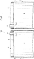
- Fig. 8 shows a perspective longitudinal sectional view of a third embodiment of an inventive multi-component cartridge 100.
- the two cartridges 1 are one inside the other arranged so that the cartridge wall 3 of the representation according to the outer cartridge 1, the cartridge wall 3 of the inner cartridge according to the representation 1 completely surrounds.
- the inner cartridge is centered in the outer cartridge, so that their longitudinal axes A coincide.
- each of the two cartridges 1, namely both the inner and the outer cartridge 1 each have a cartridge wall 3, which is made of a cardboard.
- the piston 8 belonging to the outer cartridge 1 according to the representation is designed as an annular piston in a manner known per se.
- the third embodiment it is also possible to provide an arrangement as in the third embodiment, in which only one inventively designed cartridge 1 is provided and the second cartridge is made of plastic.
- the inner cartridge 1 it is possible to design the inner cartridge 1 as a plastic tube, so that only the outer cartridge has a cartridge wall made of cardboard.
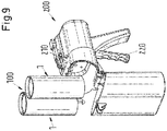
- the multi-component cartridge 100 For use of the multi-component cartridge 100, it is usually inserted into the holder of a dispensing device (dispenser) 200. Since the multi-component cartridge 100 is configured with thin cartridge walls 3, the holder of the discharge device is preferably designed such that it additionally exerts a support function on the cartridge walls 3 in order to support them during the discharge of the medium, so that the Multi-component cartridge 100 can better withstand the mechanical stress during discharge. Alternatively, it is also possible to use a separate support cartridge which is designed for multiple use, ie can be reused as often as required. The support cartridge filled with the multicomponent cartridge 100 is then inserted into the holder of the discharge device 200.
- the multi-component cartridge 100 is inserted into the holder of the discharge device 200, as the arrow without reference numeral in FIG Fig. 9 suggests.
- the discharge device is closed and a mixer 70 is attached to the discharge device 200 by means of its coupling piece 73 ( Fig. 10 ), preferably with one with a screw, snap or bayonet connection.
- the mixer 70 is not attached to the discharge device 200 but directly to the adapters 5 of the multi-component cartridge. If the mixer 70 is placed on the adapter 5, then the piercing elements 74 pierce the head parts 4 so that the two media can pass through the outlets 51 into the mixer 70.
- the discharge device 200 comprises a double plunger 210, which can be advanced by means of an activator 220.
- the double plunger 210 then exerts a force on the two pistons 8 in the receiving chambers 2, whereby they move along the longitudinal axes A of the cartridges 1 and promote the respective medium through the respective outlet 51 in the static mixer 70.
- the two media (components) meet and are intimately mixed as they pass through the mixer.
Landscapes
- Engineering & Computer Science (AREA)
- Mechanical Engineering (AREA)
- Package Specialized In Special Use (AREA)
- Coating Apparatus (AREA)
- Containers And Packaging Bodies Having A Special Means To Remove Contents (AREA)
- Closures For Containers (AREA)
Claims (14)
- Cartouche (1), comportant- au moins une chambre de réception (2) pour un fluide à distribuer, qui s'étend en direction longitudinale, et- une partie tête (4) et une paroi de cartouche (3) qui délimitent la chambre de réception (2),- dans laquelle est prévu un piston (8) qui peut être introduit dans la chambre de réception (2) à l'extrémité détournée de la partie tête (4) et qui est déplaçable en direction longitudinale avec étanchéité le long de la paroi de cartouche (3),- la paroi de cartouche (3) étant réalisée en un carton et étant reliée de façon étanche à la partie tête (4),caractérisée en ce que- il est prévu un anneau de support (11) solide en forme et- l'anneau de support (11) entoure la paroi de cartouche (3) depuis l'extérieur à l'extrémité de la chambre de réception (2) destinée à recevoir le piston (8), afin d'améliorer l'étanchement entre la paroi de cartouche (3) et le piston (8).
- Cartouche (1) selon la revendication 1,
dans laquelle la partie tête (4) est réalisée en un carton. - Cartouche (1) selon l'une des revendications précédentes,
dans laquelle la paroi de cartouche (3) ou la partie tête (4) comprend un film (31, 41) qui est prévu sur la surface de la paroi de cartouche (3) ou de la partie tête (4) délimitant la chambre de réception (2) et qui est relié de façon non détachable à la paroi de cartouche (3) ou à la partie tête (4). - Cartouche (1) selon l'une des revendications précédentes,
dans laquelle la paroi de cartouche (3) présente un second film (32) qui est prévu sur la surface extérieure de la paroi de cartouche (3) détournée de la chambre de réception (2). - Cartouche (1) selon l'une des revendications précédentes,
dans laquelle le film (31, 41) de la paroi de cartouche (3) ou de la partie tête (4) est conçu sous forme de système multicouche. - Cartouche (1) selon la revendication 1,
dans laquelle l'anneau de support (11) présente une contre-dépouille (111) qui soutient la paroi de cartouche (3) par rapport à la direction longitudinale. - Cartouche (1) selon l'une des revendications précédentes,
dans laquelle sont prévus des moyens de liaison (10) par lesquels la cartouche (1) peut être reliée à une seconde cartouche (1). - Cartouche (1) selon l'une des revendications précédentes,
dans laquelle la partie tête (4) comprend un adaptateur (5) qui présente une sortie (51) pour le fluide. - Cartouche (1) selon la revendication 7,
dans laquelle l'adaptateur (5) est réalisé en matière plastique et relié à la partie tête (4). - Cartouche à composants multiples comportant au moins deux cartouches (1), dans laquelle- au moins une cartouche (1) est conçue selon l'une des revendications 1 à 9,- les deux cartouches (1) sont agencées l'une à côté de l'autre par rapport à la direction longitudinale ou- les deux cartouches (1) sont agencées l'une à l'intérieur de l'autre, de préférence coaxialement l'une à l'intérieur de l'autre, de sorte que l'une des cartouches (1) entoure l'autre cartouche (1).
- Cartouche à composants multiples (100) selon la revendication 9, dans laquelle
les deux cartouches (1) sont fermement couplées l'une à l'autre via les moyens de liaison (10). - Cartouche à composants multiples (100) selon l'une des revendications 10 ou 11,
dans laquelle les adaptateurs (5) des cartouches (1) sont agencés et conçus pour coopérer avec un accessoire, en particulier un mélangeur (70). - Cartouche à composants multiples (100) selon la revendication 12, comportant un mélangeur (70) qui est conçu pour coopérer avec les adaptateurs (5) et qui comprend deux éléments de percement (74) dont l'un peut venir s'engager dans une sortie pour ouvrir une liaison d'écoulement avec la chambre de réception respective (2).
- Cartouche à composants multiples (100) selon l'une des revendications 10 à 13,
dans laquelle les chambres de réception (2) des deux cartouches (1) présentent des volumes différents.
Priority Applications (1)
| Application Number | Priority Date | Filing Date | Title |
|---|---|---|---|
| EP12748478.0A EP2768619B1 (fr) | 2011-10-17 | 2012-08-20 | Cartouche à plusieurs constituants |
Applications Claiming Priority (3)
| Application Number | Priority Date | Filing Date | Title |
|---|---|---|---|
| EP11185382 | 2011-10-17 | ||
| PCT/EP2012/066191 WO2013056873A1 (fr) | 2011-10-17 | 2012-08-20 | Cartouche à plusieurs composants |
| EP12748478.0A EP2768619B1 (fr) | 2011-10-17 | 2012-08-20 | Cartouche à plusieurs constituants |
Publications (2)
| Publication Number | Publication Date |
|---|---|
| EP2768619A1 EP2768619A1 (fr) | 2014-08-27 |
| EP2768619B1 true EP2768619B1 (fr) | 2017-04-19 |
Family
ID=46704663
Family Applications (1)
| Application Number | Title | Priority Date | Filing Date |
|---|---|---|---|
| EP12748478.0A Active EP2768619B1 (fr) | 2011-10-17 | 2012-08-20 | Cartouche à plusieurs constituants |
Country Status (5)
| Country | Link |
|---|---|
| US (1) | US9901946B2 (fr) |
| EP (1) | EP2768619B1 (fr) |
| KR (1) | KR20140079410A (fr) |
| CN (1) | CN103998150B (fr) |
| WO (1) | WO2013056873A1 (fr) |
Families Citing this family (19)
| Publication number | Priority date | Publication date | Assignee | Title |
|---|---|---|---|---|
| EP2468416A1 (fr) * | 2010-12-24 | 2012-06-27 | Sika Technology AG | Dispositif d'application pour matières à plusieurs composants, ensemble de cartouche et unité d'emballage |
| AU2012325253B2 (en) * | 2011-10-17 | 2016-11-17 | Sulzer Mixpac Ag | Cartridge, method for producing said cartridge, and multi-component cartridge |
| US9757763B2 (en) | 2013-10-31 | 2017-09-12 | Nordson Corporation | Side by side cartridge assemblies and related methods |
| EP2927156A1 (fr) * | 2014-03-31 | 2015-10-07 | Sulzer Mixpac AG | Cartouche et procédé de fabrication d'une cartouche |
| US20170274414A1 (en) * | 2014-09-02 | 2017-09-28 | Sika Technology Ag | Application device for applying gel-like and/or paste-like compositions and application unit for an application device of this type |
| US10363569B2 (en) | 2015-10-15 | 2019-07-30 | The Boeing Company | Applicators and systems for delivering a glutinous substance to a workpiece from an end-effector |
| US10518289B2 (en) | 2015-10-15 | 2019-12-31 | The Boeing Company | Apparatuses for applying glutinous substances |
| DE102016107911B4 (de) * | 2016-04-28 | 2020-02-27 | Heraeus Medical Gmbh | Lagerungs- und Mischsystem für pastenförmige Ausgangskomponenten mit auspressbarer Innenkartusche |
| EP3263483A1 (fr) * | 2016-07-01 | 2018-01-03 | Sulzer Mixpac AG | Cartouche, noyau, moule et procédé de fabrication d'une cartouche |
| USD859940S1 (en) * | 2017-03-16 | 2019-09-17 | Henkel Ag & Co. Kgaa | Cartridge or foil holder for a one and two component dispenser |
| DE102017222187B4 (de) * | 2017-05-31 | 2024-09-05 | Fraunhofer-Gesellschaft zur Förderung der angewandten Forschung e.V. | Anwendungseinrichtung zur Verwendung eines Kleberkits |
| WO2019031358A1 (fr) * | 2017-08-09 | 2019-02-14 | 株式会社資生堂 | Récipient de distribution, système de distribution personnalisé comprenant un récipient de distribution, et procédé de commande de distribution pour récipient de distribution |
| US12059701B2 (en) * | 2018-02-21 | 2024-08-13 | Scott Folley | Caulk tube repair system and apparatus |
| MX2021000633A (es) * | 2018-07-16 | 2021-04-19 | Ppg Ind Ohio Inc | Instrumentacion y punta aplicadora de composicion. |
| EP3826940B1 (fr) * | 2018-10-02 | 2024-04-10 | medmix Switzerland AG | Cartouche, ensemble de distribution et procédé de fabrication d'une cartouche |
| EP3632575A1 (fr) * | 2018-10-02 | 2020-04-08 | Sulzer Mixpac AG | Piston de cartouche réutilisable |
| US10870127B2 (en) * | 2018-10-02 | 2020-12-22 | Sulzer Mixpac Ag | Cartridge for a mixing and dispensing system |
| GB2584082B (en) * | 2019-05-14 | 2021-09-22 | Arrival Ltd | Two-component dispensing tool with cartridge replacement mechanism |
| DE102021116490A1 (de) | 2021-06-25 | 2022-12-29 | Saier Verpackungstechnik Gmbh & Co. Kg | Kartusche mit einem als Folie ausgebildeten Kopfstück und Stützhülse |
Family Cites Families (28)
| Publication number | Priority date | Publication date | Assignee | Title |
|---|---|---|---|---|
| US2887253A (en) * | 1956-11-07 | 1959-05-19 | R C Can Co | Slip cover and plunger for cartridge-container |
| US3311265A (en) * | 1965-06-03 | 1967-03-28 | Chem Dev Corp | Double-barreled dispensing gun |
| US3640431A (en) * | 1970-04-13 | 1972-02-08 | Rutland Fire Clay Co | Shutoff nozzle for caulking cartridge |
| DK142275B (da) * | 1978-03-14 | 1980-10-06 | Ole Simonni Mundeling Nielsen | Stempel til udpresning af en viskos eller plastisk masse fra en cylindrisk beholder eller emballage. |
| US4366919A (en) * | 1978-05-01 | 1983-01-04 | Coaxial Cartridges, Inc. | Composite cartridge and device for metering extrusion of contents |
| EP0039245A1 (fr) * | 1980-04-30 | 1981-11-04 | Black & Decker | Cartouche |
| US4371094A (en) * | 1980-07-31 | 1983-02-01 | Products Research & Chemical Corporation | Barrier two part pairing and dispensing cartridge |
| DE3708704A1 (de) * | 1987-03-18 | 1988-09-29 | Fischbach A Kunststoff Kg | Kartusche fuer pastoese massen |
| US5082147A (en) * | 1988-02-29 | 1992-01-21 | Richard Jacobs | Composition dispensing system |
| US4946081A (en) * | 1989-02-27 | 1990-08-07 | Dow Corning Corporation | Applicator nozzle for sealant cartridges and the like |
| US5443181A (en) * | 1992-09-19 | 1995-08-22 | Hilti Aktiengesellschaft | Cartridge and piston for dispensing mass |
| JPH07256178A (ja) * | 1994-03-28 | 1995-10-09 | Sunstar Eng Inc | 紙製カートリッジ容器及びその使用方法 |
| DE19500782A1 (de) * | 1995-01-13 | 1996-07-18 | Bayer Ag | Vorrichtung zum Mischen und Ausbringen einer Formmasse |
| US5918772A (en) * | 1995-03-13 | 1999-07-06 | Wilhelm A. Keller | Bayonet fastening device for the attachment of an accessory to a multiple component cartridge or dispensing device |
| DE19618693A1 (de) * | 1996-05-09 | 1997-11-13 | Upat Max Langensiepen Kg | Kartusche für Zweikomponentenmassen |
| DE19943877B4 (de) * | 1999-09-14 | 2008-08-07 | Alfred Fischbach Kg Kunststoff-Spritzgusswerk | Zweikomponentenkartusche für fließfähige Medien |
| US20030051610A1 (en) * | 1999-12-17 | 2003-03-20 | Roland Dux | Adapter, device and method for sampling from a multichamber bag, use of said adapter and bag packaging |
| US6796460B2 (en) * | 2001-06-14 | 2004-09-28 | Hosokawa Yoko Co., Ltd | Cartridge for fluid material and dispensing apparatus for such a cartridge |
| US20030136859A1 (en) * | 2002-01-18 | 2003-07-24 | 3M Innovative Properties Company | Method of applying two-component pavement markings and apparatus |
| US6705756B2 (en) * | 2002-03-12 | 2004-03-16 | Chemque, Incorporated | Apparatus and method for mixing and dispensing components of a composition |
| US7163130B2 (en) * | 2002-10-18 | 2007-01-16 | Luc Marcel Lafond | Portable gas powered fluid dispenser |
| EP1599293A1 (fr) * | 2003-03-04 | 2005-11-30 | LL Lafond Intellectual Properties Inc. | Buse pour la distribution de materiaux visqueux |
| US7306130B2 (en) * | 2003-06-27 | 2007-12-11 | Sulzer Chemtech Ag | Seal for a two-component cartridge |
| CH699391A1 (de) * | 2008-08-19 | 2010-02-26 | Medmix Systems Ag | Austraganordnung mit einer Kartusche mit Beutel. |
| DE102008041984A1 (de) * | 2008-09-11 | 2010-03-18 | Hilti Aktiengesellschaft | Kassette für mehrkomponentige Massen |
| DE102009031306A1 (de) * | 2009-06-30 | 2011-01-05 | Heraeus Kulzer Gmbh | Einweg-Kartuschen zum Lagern und Ausbringen dentaler Zweikomponenten-Abformmassen |
| EP2485852B1 (fr) * | 2009-10-06 | 2013-10-30 | Medmix Systems AG | Agencement de distribution doté d'un dispositif de raccordement entre une cartouche à plusieurs composants et un élément d'accessoire |
| EP2546166B1 (fr) * | 2011-07-15 | 2014-05-14 | Sulzer Mixpac AG | Sécurisation de piston |
-
2012
- 2012-08-20 WO PCT/EP2012/066191 patent/WO2013056873A1/fr active Application Filing
- 2012-08-20 KR KR1020147010138A patent/KR20140079410A/ko not_active Application Discontinuation
- 2012-08-20 CN CN201280050864.3A patent/CN103998150B/zh not_active Expired - Fee Related
- 2012-08-20 EP EP12748478.0A patent/EP2768619B1/fr active Active
- 2012-08-20 US US14/236,156 patent/US9901946B2/en active Active
Non-Patent Citations (1)
| Title |
|---|
| None * |
Also Published As
| Publication number | Publication date |
|---|---|
| KR20140079410A (ko) | 2014-06-26 |
| US9901946B2 (en) | 2018-02-27 |
| EP2768619A1 (fr) | 2014-08-27 |
| CN103998150A (zh) | 2014-08-20 |
| US20140158717A1 (en) | 2014-06-12 |
| WO2013056873A1 (fr) | 2013-04-25 |
| CN103998150B (zh) | 2017-07-21 |
Similar Documents
| Publication | Publication Date | Title |
|---|---|---|
| EP2768619B1 (fr) | Cartouche à plusieurs constituants | |
| EP2768620B1 (fr) | Cartouche et cartouche à plusieurs composants | |
| DE102010049378B4 (de) | Kartuschenanordnung mit einer Doppelkartusche | |
| EP2794119B1 (fr) | Cartouche, procédé de fabrication de celle-ci, ainsi que cartouche à plusieurs composants | |
| EP2560888B1 (fr) | Cartouche pouvant tenir debout, dispositif de sortie pour celle-ci et procédé d'utilisation de la cartouche | |
| EP3102503B1 (fr) | Cartouche et procédé de fabrication d'une cartouche | |
| EP0663348B1 (fr) | Dispositif pour le vidage d'un sac tubulaire | |
| EP1982922B1 (fr) | Récipient et procédé destiné à l'ouverture d'un récipient | |
| EP3405293B1 (fr) | Emballage de feuilles et bloc comprenant un dispositif de compression et un emballage de feuilles | |
| DE20311287U1 (de) | Mehrkomponentenkartusche | |
| EP2511194B1 (fr) | Cartouche plastique et procédé de fabrication d'une cartouche plastique | |
| EP0942787B1 (fr) | Dispositif pour stocker, exprimer et doser des compositions a deux composants | |
| EP3365242B1 (fr) | Dispositif de fermeture d'un récipient | |
| WO2017102680A1 (fr) | Module constitué par un emballage en feuille et un dispositif d'extrusion ainsi qu'emballage en feuille | |
| WO1991007333A1 (fr) | Cartouches en feuille pour un ou deux composants destinees a etre employees sous forme de cartouches reutilisables pour des pistolets a mastiquer | |
| EP3834951A1 (fr) | Cartouche pour un dispositif d'extrusion | |
| EP4072970B1 (fr) | Cartouche et procédé de fabrication d'une cartouche | |
| EP3589556B1 (fr) | Emballage de contenant et procédé pour sa fabrication | |
| EP3741469B1 (fr) | Cartouche à plusieurs chambres et son procédé de remplissage | |
| DE102008007306A1 (de) | Auspressvorrichtung für plastische Massen | |
| DE10310162A1 (de) | Kartusche zum Ausbringen von ein oder mehreren Komponenten einer Masse | |
| EP0824484A1 (fr) | Cartouche et systeme de cartouche | |
| WO2020151939A1 (fr) | Système d'application à double fermeture inviolable | |
| EP3829993A1 (fr) | Emballage de tube et procédé pour le fabriquer | |
| DE9017324U1 (de) | Vorratsbehälter für fließfähige Substanzen |
Legal Events
| Date | Code | Title | Description |
|---|---|---|---|
| PUAI | Public reference made under article 153(3) epc to a published international application that has entered the european phase |
Free format text: ORIGINAL CODE: 0009012 |
|
| 17P | Request for examination filed |
Effective date: 20140116 |
|
| AK | Designated contracting states |
Kind code of ref document: A1 Designated state(s): AL AT BE BG CH CY CZ DE DK EE ES FI FR GB GR HR HU IE IS IT LI LT LU LV MC MK MT NL NO PL PT RO RS SE SI SK SM TR |
|
| DAX | Request for extension of the european patent (deleted) | ||
| 17Q | First examination report despatched |
Effective date: 20160907 |
|
| GRAP | Despatch of communication of intention to grant a patent |
Free format text: ORIGINAL CODE: EPIDOSNIGR1 |
|
| INTG | Intention to grant announced |
Effective date: 20161102 |
|
| GRAS | Grant fee paid |
Free format text: ORIGINAL CODE: EPIDOSNIGR3 |
|
| GRAA | (expected) grant |
Free format text: ORIGINAL CODE: 0009210 |
|
| AK | Designated contracting states |
Kind code of ref document: B1 Designated state(s): AL AT BE BG CH CY CZ DE DK EE ES FI FR GB GR HR HU IE IS IT LI LT LU LV MC MK MT NL NO PL PT RO RS SE SI SK SM TR |
|
| REG | Reference to a national code |
Ref country code: GB Ref legal event code: FG4D Free format text: NOT ENGLISH |
|
| REG | Reference to a national code |
Ref country code: CH Ref legal event code: EP Ref country code: CH Ref legal event code: NV Representative=s name: DR. GRAF AND PARTNER AG INTELLECTUAL PROPERTY, CH |
|
| REG | Reference to a national code |
Ref country code: AT Ref legal event code: REF Ref document number: 885440 Country of ref document: AT Kind code of ref document: T Effective date: 20170515 |
|
| REG | Reference to a national code |
Ref country code: IE Ref legal event code: FG4D Free format text: LANGUAGE OF EP DOCUMENT: GERMAN |
|
| REG | Reference to a national code |
Ref country code: DE Ref legal event code: R096 Ref document number: 502012010123 Country of ref document: DE |
|
| REG | Reference to a national code |
Ref country code: NL Ref legal event code: MP Effective date: 20170419 |
|
| REG | Reference to a national code |
Ref country code: LT Ref legal event code: MG4D |
|
| PG25 | Lapsed in a contracting state [announced via postgrant information from national office to epo] |
Ref country code: NL Free format text: LAPSE BECAUSE OF FAILURE TO SUBMIT A TRANSLATION OF THE DESCRIPTION OR TO PAY THE FEE WITHIN THE PRESCRIBED TIME-LIMIT Effective date: 20170419 |
|
| PG25 | Lapsed in a contracting state [announced via postgrant information from national office to epo] |
Ref country code: HR Free format text: LAPSE BECAUSE OF FAILURE TO SUBMIT A TRANSLATION OF THE DESCRIPTION OR TO PAY THE FEE WITHIN THE PRESCRIBED TIME-LIMIT Effective date: 20170419 Ref country code: GR Free format text: LAPSE BECAUSE OF FAILURE TO SUBMIT A TRANSLATION OF THE DESCRIPTION OR TO PAY THE FEE WITHIN THE PRESCRIBED TIME-LIMIT Effective date: 20170720 Ref country code: ES Free format text: LAPSE BECAUSE OF FAILURE TO SUBMIT A TRANSLATION OF THE DESCRIPTION OR TO PAY THE FEE WITHIN THE PRESCRIBED TIME-LIMIT Effective date: 20170419 Ref country code: LT Free format text: LAPSE BECAUSE OF FAILURE TO SUBMIT A TRANSLATION OF THE DESCRIPTION OR TO PAY THE FEE WITHIN THE PRESCRIBED TIME-LIMIT Effective date: 20170419 Ref country code: FI Free format text: LAPSE BECAUSE OF FAILURE TO SUBMIT A TRANSLATION OF THE DESCRIPTION OR TO PAY THE FEE WITHIN THE PRESCRIBED TIME-LIMIT Effective date: 20170419 Ref country code: NO Free format text: LAPSE BECAUSE OF FAILURE TO SUBMIT A TRANSLATION OF THE DESCRIPTION OR TO PAY THE FEE WITHIN THE PRESCRIBED TIME-LIMIT Effective date: 20170719 |
|
| PG25 | Lapsed in a contracting state [announced via postgrant information from national office to epo] |
Ref country code: PL Free format text: LAPSE BECAUSE OF FAILURE TO SUBMIT A TRANSLATION OF THE DESCRIPTION OR TO PAY THE FEE WITHIN THE PRESCRIBED TIME-LIMIT Effective date: 20170419 Ref country code: IS Free format text: LAPSE BECAUSE OF FAILURE TO SUBMIT A TRANSLATION OF THE DESCRIPTION OR TO PAY THE FEE WITHIN THE PRESCRIBED TIME-LIMIT Effective date: 20170819 Ref country code: RS Free format text: LAPSE BECAUSE OF FAILURE TO SUBMIT A TRANSLATION OF THE DESCRIPTION OR TO PAY THE FEE WITHIN THE PRESCRIBED TIME-LIMIT Effective date: 20170419 Ref country code: SE Free format text: LAPSE BECAUSE OF FAILURE TO SUBMIT A TRANSLATION OF THE DESCRIPTION OR TO PAY THE FEE WITHIN THE PRESCRIBED TIME-LIMIT Effective date: 20170419 Ref country code: BG Free format text: LAPSE BECAUSE OF FAILURE TO SUBMIT A TRANSLATION OF THE DESCRIPTION OR TO PAY THE FEE WITHIN THE PRESCRIBED TIME-LIMIT Effective date: 20170719 Ref country code: LV Free format text: LAPSE BECAUSE OF FAILURE TO SUBMIT A TRANSLATION OF THE DESCRIPTION OR TO PAY THE FEE WITHIN THE PRESCRIBED TIME-LIMIT Effective date: 20170419 |
|
| REG | Reference to a national code |
Ref country code: DE Ref legal event code: R097 Ref document number: 502012010123 Country of ref document: DE |
|
| PG25 | Lapsed in a contracting state [announced via postgrant information from national office to epo] |
Ref country code: CZ Free format text: LAPSE BECAUSE OF FAILURE TO SUBMIT A TRANSLATION OF THE DESCRIPTION OR TO PAY THE FEE WITHIN THE PRESCRIBED TIME-LIMIT Effective date: 20170419 Ref country code: RO Free format text: LAPSE BECAUSE OF FAILURE TO SUBMIT A TRANSLATION OF THE DESCRIPTION OR TO PAY THE FEE WITHIN THE PRESCRIBED TIME-LIMIT Effective date: 20170419 Ref country code: DK Free format text: LAPSE BECAUSE OF FAILURE TO SUBMIT A TRANSLATION OF THE DESCRIPTION OR TO PAY THE FEE WITHIN THE PRESCRIBED TIME-LIMIT Effective date: 20170419 Ref country code: SK Free format text: LAPSE BECAUSE OF FAILURE TO SUBMIT A TRANSLATION OF THE DESCRIPTION OR TO PAY THE FEE WITHIN THE PRESCRIBED TIME-LIMIT Effective date: 20170419 Ref country code: EE Free format text: LAPSE BECAUSE OF FAILURE TO SUBMIT A TRANSLATION OF THE DESCRIPTION OR TO PAY THE FEE WITHIN THE PRESCRIBED TIME-LIMIT Effective date: 20170419 |
|
| PLBE | No opposition filed within time limit |
Free format text: ORIGINAL CODE: 0009261 |
|
| STAA | Information on the status of an ep patent application or granted ep patent |
Free format text: STATUS: NO OPPOSITION FILED WITHIN TIME LIMIT |
|
| PG25 | Lapsed in a contracting state [announced via postgrant information from national office to epo] |
Ref country code: IT Free format text: LAPSE BECAUSE OF FAILURE TO SUBMIT A TRANSLATION OF THE DESCRIPTION OR TO PAY THE FEE WITHIN THE PRESCRIBED TIME-LIMIT Effective date: 20170419 Ref country code: SM Free format text: LAPSE BECAUSE OF FAILURE TO SUBMIT A TRANSLATION OF THE DESCRIPTION OR TO PAY THE FEE WITHIN THE PRESCRIBED TIME-LIMIT Effective date: 20170419 |
|
| 26N | No opposition filed |
Effective date: 20180122 |
|
| PG25 | Lapsed in a contracting state [announced via postgrant information from national office to epo] |
Ref country code: MC Free format text: LAPSE BECAUSE OF FAILURE TO SUBMIT A TRANSLATION OF THE DESCRIPTION OR TO PAY THE FEE WITHIN THE PRESCRIBED TIME-LIMIT Effective date: 20170419 |
|
| GBPC | Gb: european patent ceased through non-payment of renewal fee |
Effective date: 20170820 |
|
| REG | Reference to a national code |
Ref country code: FR Ref legal event code: ST Effective date: 20180430 |
|
| REG | Reference to a national code |
Ref country code: IE Ref legal event code: MM4A |
|
| PG25 | Lapsed in a contracting state [announced via postgrant information from national office to epo] |
Ref country code: SI Free format text: LAPSE BECAUSE OF FAILURE TO SUBMIT A TRANSLATION OF THE DESCRIPTION OR TO PAY THE FEE WITHIN THE PRESCRIBED TIME-LIMIT Effective date: 20170419 |
|
| REG | Reference to a national code |
Ref country code: BE Ref legal event code: MM Effective date: 20170831 |
|
| PG25 | Lapsed in a contracting state [announced via postgrant information from national office to epo] |
Ref country code: LU Free format text: LAPSE BECAUSE OF NON-PAYMENT OF DUE FEES Effective date: 20170820 |
|
| PG25 | Lapsed in a contracting state [announced via postgrant information from national office to epo] |
Ref country code: IE Free format text: LAPSE BECAUSE OF NON-PAYMENT OF DUE FEES Effective date: 20170820 Ref country code: GB Free format text: LAPSE BECAUSE OF NON-PAYMENT OF DUE FEES Effective date: 20170820 |
|
| PG25 | Lapsed in a contracting state [announced via postgrant information from national office to epo] |
Ref country code: BE Free format text: LAPSE BECAUSE OF NON-PAYMENT OF DUE FEES Effective date: 20170831 Ref country code: FR Free format text: LAPSE BECAUSE OF NON-PAYMENT OF DUE FEES Effective date: 20170831 |
|
| PG25 | Lapsed in a contracting state [announced via postgrant information from national office to epo] |
Ref country code: MT Free format text: LAPSE BECAUSE OF FAILURE TO SUBMIT A TRANSLATION OF THE DESCRIPTION OR TO PAY THE FEE WITHIN THE PRESCRIBED TIME-LIMIT Effective date: 20170419 |
|
| REG | Reference to a national code |
Ref country code: AT Ref legal event code: MM01 Ref document number: 885440 Country of ref document: AT Kind code of ref document: T Effective date: 20170820 |
|
| PG25 | Lapsed in a contracting state [announced via postgrant information from national office to epo] |
Ref country code: AT Free format text: LAPSE BECAUSE OF NON-PAYMENT OF DUE FEES Effective date: 20170820 |
|
| PGFP | Annual fee paid to national office [announced via postgrant information from national office to epo] |
Ref country code: CH Payment date: 20180822 Year of fee payment: 7 |
|
| PG25 | Lapsed in a contracting state [announced via postgrant information from national office to epo] |
Ref country code: HU Free format text: LAPSE BECAUSE OF FAILURE TO SUBMIT A TRANSLATION OF THE DESCRIPTION OR TO PAY THE FEE WITHIN THE PRESCRIBED TIME-LIMIT; INVALID AB INITIO Effective date: 20120820 |
|
| PG25 | Lapsed in a contracting state [announced via postgrant information from national office to epo] |
Ref country code: CY Free format text: LAPSE BECAUSE OF FAILURE TO SUBMIT A TRANSLATION OF THE DESCRIPTION OR TO PAY THE FEE WITHIN THE PRESCRIBED TIME-LIMIT Effective date: 20170419 |
|
| PG25 | Lapsed in a contracting state [announced via postgrant information from national office to epo] |
Ref country code: MK Free format text: LAPSE BECAUSE OF FAILURE TO SUBMIT A TRANSLATION OF THE DESCRIPTION OR TO PAY THE FEE WITHIN THE PRESCRIBED TIME-LIMIT Effective date: 20170419 |
|
| PG25 | Lapsed in a contracting state [announced via postgrant information from national office to epo] |
Ref country code: TR Free format text: LAPSE BECAUSE OF FAILURE TO SUBMIT A TRANSLATION OF THE DESCRIPTION OR TO PAY THE FEE WITHIN THE PRESCRIBED TIME-LIMIT Effective date: 20170419 |
|
| PG25 | Lapsed in a contracting state [announced via postgrant information from national office to epo] |
Ref country code: CH Free format text: LAPSE BECAUSE OF NON-PAYMENT OF DUE FEES Effective date: 20190831 Ref country code: LI Free format text: LAPSE BECAUSE OF NON-PAYMENT OF DUE FEES Effective date: 20190831 Ref country code: PT Free format text: LAPSE BECAUSE OF FAILURE TO SUBMIT A TRANSLATION OF THE DESCRIPTION OR TO PAY THE FEE WITHIN THE PRESCRIBED TIME-LIMIT Effective date: 20170419 |
|
| PG25 | Lapsed in a contracting state [announced via postgrant information from national office to epo] |
Ref country code: AL Free format text: LAPSE BECAUSE OF FAILURE TO SUBMIT A TRANSLATION OF THE DESCRIPTION OR TO PAY THE FEE WITHIN THE PRESCRIBED TIME-LIMIT Effective date: 20170419 |
|
| REG | Reference to a national code |
Ref country code: DE Ref legal event code: R081 Ref document number: 502012010123 Country of ref document: DE Owner name: MEDMIX SWITZERLAND AG, CH Free format text: FORMER OWNER: SULZER MIXPAC AG, HAAG, CH |
|
| P01 | Opt-out of the competence of the unified patent court (upc) registered |
Effective date: 20230505 |
|
| PGFP | Annual fee paid to national office [announced via postgrant information from national office to epo] |
Ref country code: DE Payment date: 20230821 Year of fee payment: 12 |