EP2765703A2 - System und Verfahren zur Steuerung elektrischer Maschinen - Google Patents
System und Verfahren zur Steuerung elektrischer Maschinen Download PDFInfo
- Publication number
- EP2765703A2 EP2765703A2 EP14154308.2A EP14154308A EP2765703A2 EP 2765703 A2 EP2765703 A2 EP 2765703A2 EP 14154308 A EP14154308 A EP 14154308A EP 2765703 A2 EP2765703 A2 EP 2765703A2
- Authority
- EP
- European Patent Office
- Prior art keywords
- controller
- current
- voltage
- link voltage
- accordance
- Prior art date
- Legal status (The legal status is an assumption and is not a legal conclusion. Google has not performed a legal analysis and makes no representation as to the accuracy of the status listed.)
- Withdrawn
Links
Images


Classifications
-
- H—ELECTRICITY
- H02—GENERATION; CONVERSION OR DISTRIBUTION OF ELECTRIC POWER
- H02P—CONTROL OR REGULATION OF ELECTRIC MOTORS, ELECTRIC GENERATORS OR DYNAMO-ELECTRIC CONVERTERS; CONTROLLING TRANSFORMERS, REACTORS OR CHOKE COILS
- H02P6/00—Arrangements for controlling synchronous motors or other dynamo-electric motors using electronic commutation dependent on the rotor position; Electronic commutators therefor
- H02P6/14—Electronic commutators
-
- H—ELECTRICITY
- H02—GENERATION; CONVERSION OR DISTRIBUTION OF ELECTRIC POWER
- H02P—CONTROL OR REGULATION OF ELECTRIC MOTORS, ELECTRIC GENERATORS OR DYNAMO-ELECTRIC CONVERTERS; CONTROLLING TRANSFORMERS, REACTORS OR CHOKE COILS
- H02P23/00—Arrangements or methods for the control of AC motors characterised by a control method other than vector control
- H02P23/26—Power factor control [PFC]
Definitions
- the field of the disclosure relates generally to electric motor controllers, and more specifically to methods and a controller for reducing size and costs of motor controllers for electric motors.
- Devices commonly known as electronic motor controllers are utilized to control the operation of certain electric motors. At least some known motor controllers have attempted to reduce cost and save resources by replacing large-capacity smoothing capacitors with small-capacity capacitors. Because of the small-capacity capacitor, a rectified input voltage to be applied to an inverter is unable to be properly smoothed and has a pulsating waveform. The voltage of the pulsating waveform has a frequency about twice that of an output voltage of an alternating current (AC) power supply to which it is connected.
- AC alternating current
- a sinusoidal input current may be sacrificed, which can lead to a poor power factor for the electric motor.
- Active power factor correction devices are known to correct the power factor, but are typically large in size and are often costly.
- at least some known motor controllers apply a torque command to be synchronous with line input voltage to correct poor power factor.
- measuring line input voltage necessitates an additional isolated voltage sensor, which increases the system cost.
- a motor controller in one aspect, includes an inverter configured to drive an electric motor, a rectifier configured to rectify an alternating current (AC) input current and to output the rectified AC input current to the inverter, and a controller coupled to the inverter.
- the controller is configured to improve a power factor of the motor controller by controlling the AC input current based on a direct current (DC) link voltage measurement.
- DC direct current
- a method of controlling an electric motor using a motor controller includes controlling an AC input current based on a DC link voltage measurement to improve a power factor of the motor controller.
- a system in yet another aspect, includes an electric motor, an inverter configured to drive the electric motor, and a motor controller coupled to the inverter.
- the motor controller includes a rectifier and is configured to improve a power factor of the motor controller by controlling an AC input current based on a DC link voltage measurement.
- the embodiments described herein relate to electric motor controllers and methods of operating the same. More particularly, the embodiments relate to a motor controller that eliminates large filter capacitors and maintains a high power factor for an electric motor. More particularly, the embodiments relate to a motor controller configured to control AC input current based on based on a direct current (DC) link voltage measurement to facilitate improving a power factor of the electric motor.
- DC direct current
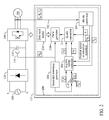
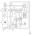
- FIG. 1 is a block diagram of an electric motor system 100 that includes a motor controller 102.
- electric motor system 100 also includes an electric motor 104, an inverter 106 coupled to electric motor 104, and a power supply 108 coupled to motor controller 102.
- electric motor 102 includes a permanent magnet synchronous motor.
- any type of electric motor may be used that enables electric motor system 100 to function as described herein.
- power supply 108 supplies a single-phase alternating current (AC) voltage to motor controller 102.
- AC alternating current
- power supply 108 may supply three-phase AC or any other type of input voltage that enables electric motor system 100 to function as described herein.
- Inverter 106 conditions a pulsed DC voltage received from motor controller 102, and supplies it to electric motor 104, where it is used drive electric motor 104.
- inverter 106 converts the pulsed DC voltage to a three-phase AC voltage.
- inverter 106 converts the pulsed DC voltage to any type of voltage that enables electric motor system 100 to function as described herein.
- motor controller 102 includes a rectifier 110 configured to rectify an alternating current (AC) input current and to output the rectified AC input current to inverter 106.
- a controller 112 which may sometimes be referred to as a microcontroller/DSP, is programmed to control operation of a rotating machine portion (not shown) of electric motor 104.
- Six pulse width modulated signals are utilized to induce rotation of the rotating machine, via inverter 106, which enables electric motor 104 to be referred to as a three-phase motor.
- Signals received from the rotating machine at controller 112 include signals relating to the current drawn by each of the phases and an AC input current, or DC bus voltage.
- Controller 112 is coupled to inverter 106 and is configured to increase a power factor of electric motor 104 by controlling the AC input current based on a direct current (DC) link voltage measurement, as described in more detail herein.
- DC direct current
- motor controller 102 includes a low-capacitance capacitor 114 for storing small amounts of energy when input voltage is available. Capacitor 114 also supplies power to the electronics of motor controller 102. In one embodiment, film capacitor 114 has a capacitance of about 2 ⁇ F. Capacitor 114 may have a capacitance between about 0.1 ⁇ F/kW and about 10 ⁇ F/kW. The use of bulky, unreliable electrolytic filter capacitors in motor controller 102 is avoided.
- Motor controller 102 also includes a voltage sensor 116 coupled across capacitor 114.
- Voltage sensor 116 is configured to measure a DC link voltage across capacitor 114.
- Voltage sensor 116 provides a DC link voltage measurement to controller 112 for use in controlling electric motor 102 to increase a power factor of electric motor by controlling the AC input current based on the DC link voltage measurement.
- controller 112 is configured to implement an algorithm configured to increase power factor based on the DC link voltage measurement from voltage sensor 116.
- FIG 2 is a block diagram of an exemplary power factor correction algorithm 200 that may be implemented by motor controller 102 (shown in Figure 1 ).
- controller 102 is configured to implement the algorithm to determine a q-axis reference value based on measured DC link voltage.
- motor phase currents I a , I b , and I c are sensed using current sensors 202.
- An abc-dq converter 204 converts the three-phase current values to a two-phase d-q coordinate system, giving measured current values I d and Iq, which are input into a d-q axis current controller 206.
- a sinusoidal waveform generator 208 receives a measured DC link voltage from voltage sensor 116 (shown in Figure 1 ) and generates a sinusoidal waveform.
- the sinusoidal waveform is multiplied by a current reference signal I q * at multiplier 210.
- I q * represents a torque component of current.
- the resulting I q * current reference is input into d-q axis current controller 206.
- the I q * has twice the line frequency (i.e., 100Hz or 120Hz), and is in phase (or slightly advanced/delayed) with input line voltage from power supply 108 (shown in Figure 1 ).
- the I q * and I d * (flux-linkage component of current) reference signals are input into d-q axis current controller 206.
- D-q axis current controller 206 processes the I q * and I d * reference signals with the measured current values I d and I q .
- D-q axis current controller 206 outputs voltage reference signals u q and u d .
- Voltage reference signals u q and u d are converted back into three-phase values by a dq-abc converter 212.
- the three-phase voltage reference signals u q and u d are input into a pulse width modulator (PWM) 214, which has a six-step transformation with six outputs that drive inverter 106.
- PWM pulse width modulator
- the signal output by PWM 214 is limited by a duty cycle limiter 216 before being transmitted to inverter 106.
- electric motor 104 is controlled based on the availability of power. More specifically, controller 112 receives the measured DC link voltage from voltage sensor 116 and outputs the sinusoidal waveform. This waveform is multiplied by torque command I q * to become the q-axis current reference I q *. Accordingly, controller 112 controls AC input current based on the DC link voltage measurement, while increasing the power factor of electric motor 104.
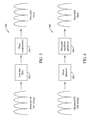
- FIG 3 is a simplified block diagram of an exemplary sinusoidal waveform generation device 300 that may be used by the sinusoidal waveform generator shown in Figure 2 .
- sinusoidal waveform generation device 300 includes a low pass filter 302 coupled to a phase compensator 304.
- Low pass filter 302 is configured to have a cut-off frequency lower than a switching frequency of inverter 106 (shown in Figures 1 and 2 ), but higher than twice the line frequency (100Hz or 120Hz). Such configuration maintains the 100Hz or 120Hz frequency component in the DC link voltage.
- Low pass filter 302 filters out a high frequency component of the DC link voltage and transmits it to phase compensator 304.
- phase compensator 304 is provided to correct the phase of the DC link voltage.
- the sinusoidal waveform is sent to multiplier 210 (shown in Figure 2 ) to generate the q-axis reference.
- FIG 4 is a simplified block diagram of an exemplary sinusoidal waveform generation device 400 that may be used by the sinusoidal waveform generator shown in Figure 2 .
- sinusoidal waveform generation device 400 includes a phase detector 402 coupled to a sinusoidal generator 404.
- phase detector 402 implements one or more phase detection algorithms to determine the phase of the measured DC link voltage.
- the algorithms may include a phase lock loop and/or a zero crossing point detection method.
- Sinusoidal generator 402 uses the phase of the measured DC link voltage to generate a sinusoidal waveform.
- the sinusoidal waveform is then sent to multiplier 210 (shown in Figure 2 ) to generate the q-axis reference.
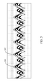
- FIG 5 illustrates a waveform chart of input signals achieved using the exemplary power factor correction algorithm shown in Figure 2 .
- AC line voltage 500 is at 60 Hertz (Hz.).
- AC line current 502 has a quasi-sinusoidal shape and is in-phase or substantially in-phase with AC line voltage 500. Because I q is modulated near 120 Hz, AC line current 502 is forced to follow the sinusoidal shape of AC line voltage 500, leading to a higher power factor for motor controller 102 (shown in Figure 1 ).
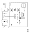
- FIG 6 is a block diagram of a first alternative power factor correction algorithm 600 that may be implemented by motor controller 102 (shown in Figure 1 ).
- controller 102 is configured to implement the algorithm to smooth the DC link voltage before generating a pulse width modulation (PWM) signal.
- PWM pulse width modulation
- motor phase currents I a , I b , and I c are sensed using current sensors 602.
- An abc-dq converter 604 converts the three-phase current values to a two-phase d-q coordinate system, giving measured current values I d and I q , which are input into a d-q axis current controller 606.
- D-q axis current controller 606 processes the I q * and I d * reference signals with the measured current values I d and I q .
- D-q axis current controller 606 outputs voltage reference signals u q and u d .
- Voltage reference signals u q and u d are converted back into three-phase values by a dq-abc converter 608.
- the three-phase voltage reference signals u q and u d are input into a PWM generator 610, which has a six-step transformation with six outputs that drive inverter 106.
- a voltage smoother 612 is coupled between voltage sensor 116 and PWM generator 610. Because DC link voltage is needed for PWM duty ratio calculation, the switching harmonics in the DC link voltage may be introduced to PWM duty ratio, causing resonance issues. Voltage smoother 612 smoothes the DC link voltage and avoids such resonance issues, which improves the power factor of motor controller 102 and improves the current waveform of electric motor 104.
- voltage smoother 612 includes sinusoidal waveform generation device 300 (shown in Figure 3 ), including low pass filter 302 and phase compensator 304.
- voltage smoother 612 includes sinusoidal waveform generation device 400 (shown in Figure 4 ), including phase detector 402 and sinusoidal generator 404.
- PWM generator 610 then outputs three-phase voltage command signals V a , V b , and V c to a duty cycle limiter 614.
- FIG 7 is a block diagram of a second alternative power factor correction algorithm 700 that may be implemented by motor controller 102 (shown in Figure 1 ).
- controller 102 is configured to implement the algorithm to control a duty cycle of at least one voltage commanded by said controller.
- motor phase currents I a , I b , and I c are sensed using current sensors 702.
- An abc-dq converter 704 converts the three-phase current values to a two-phase d-q coordinate system, giving measured current values I d and I q , which are input into a d-q axis current controller 706.
- D-q axis current controller 706 processes the I q * and I d * reference signals with the measured current values I d and I q .
- D-q axis current controller 706 outputs voltage reference signals u q and u d .
- Voltage reference signals u q and u d are converted back into three-phase values by a dq-abc converter 708.
- the three-phase voltage reference signals u q and u d are input into a PWM generator 710, which has a six-step transformation with six outputs that drive inverter 106.
- PWM generator 710 then outputs three-phase voltage command signals V a , V b , and V c to a duty cycle limiter 712.
- Duty cycle limiter 712 employs different types of limiting functions 714 around the zero crossings of the AC line current, including but not limited to, linear and/or polynomial limiting functions.
- duty cycle limiter 712 uses a sinusoidal limiting function derived and/or synchronized from AC power source 108. After applying limiting function 714 to voltage command signals V a , V b , and V c , duty cycle limiter 712 outputs modulated voltage reference signals V a *, V b *, and V c * to inverter 106 for driving electric motor 104.
- FIG 8 illustrates a waveform chart of input signals achieved using the second alternative power factor correction algorithm shown in Figure 7 .
- Controlling the duty cycle includes controlling the AC line current 800 to shape it near the vicinity of the zero crossings of the AC source voltage 802. By doing so, sharp transitions 804 in AC line current 800 are smoothed and the power factor is improved, as can be seen in the duty cycle limiting enabled graph.
- Duty cycle limiter 712 also assists in the prevention of oscillations in the AC line current (or bus voltage) by gradual regulation of the load flow independently of the output swings in d-q axis current controller 706.
- FIG 9 is a block diagram of a third alternative power factor correction algorithm 900 that may be implemented by motor controller 102 shown in Figure 1 .
- controller 102 is configured to implement an algorithm to increase the power factor based on the DC link voltage measurement and an AC line current measurement.
- motor phase currents I a , I b , and I c are sensed using current sensors 902.
- An abc-dq converter 904 converts the three-phase current values to a two-phase d-q coordinate system, giving measured current values I d and I q , which are input into a d-q axis current controller 906.
- a current reference generator 908 receives a measured DC link voltage from voltage sensor 116 (shown in Figure 1 ) and generates a sinusoidal AC current reference signal I AC *. Additionally, AC line current I AC is measured using a current sensor 910. I AC is subtracted from I AC * in summing junction 912. The resultant signal is multiplied by a torque command I q *' at multiplier 914. The resulting I q * current reference is input into d-q axis current controller 906.
- D-q axis current controller 906 processes the I q * and I d * reference signals with the measured current values I d and I q .
- D-q axis current controller 906 outputs voltage reference signals u q and u d .
- Voltage reference signals u q and u d are converted back into three-phase values by a dq-abc converter 916.
- the three-phase voltage reference signals u q and u d are input into a PWM generator 918, which has a six-step transformation with six outputs that drive inverter 106.
- PWM generator 918 then outputs three-phase voltage command signals V a , V b , and V c to a duty cycle limiter 920.
- Duty cycle limiter 920 uses the values inputted to adjust the duty cycle of the AC line current so as to optimize the power flow to achieve sinusoidal AC input line current.
- Figure 10 illustrates a waveform chart of input signals achieved using the third alternative power factor correction algorithm shown in Figure 9 .
- AC line voltage 1000 and AC line current 1002 are in-phase, or substantially in-phase to achieve a near unity power factor.
- the near unity power factor is accomplished by sensing AC input current and controlling or reconstructing it to have a sinusoidal waveform to match the AC input voltage.
- FIG 11 is a block diagram of a fourth alternative power factor correction algorithm 1100 that may be implemented by motor controller 102 (shown in Figure 1 ).
- controller 102 is configured to implement an algorithm to increase the power factor based on the DC link voltage measurement and an AC line current measurement, and adjust a harmonic content of electric motor 104 (shown in Figure 1 ).
- motor phase currents I a , I b , and I c are sensed using current sensors 1102.
- An abc-dq converter 1104 converts the three-phase current values to a two-phase d-q coordinate system, giving measured current values I d and I q , which are input into a d-q axis current controller 1106.
- a current reference generator 1108 receives a measured DC link voltage from voltage sensor 116 (shown in Figure 1 ) and generates a fundamental AC current reference signal I AC_fundamental *. Additionally, a harmonic generation unit 1110 generates a harmonic signal I AC_harmonics *. I AC_fundamental * and I AC_harmonics * are summed at first summing junction 1112 to form an AC current reference signal I AC *. Modification of the harmonic content enables motor controller 102 to achieve an improved power factor for electric motor 104 (shown in Figure 1 ).
- AC line current I AC is measured using a current sensor 1114.
- I AC is subtracted from I AC * in second summing junction 1116.
- the resultant signal is multiplied by a torque command I q *' at multiplier 1118.
- the resulting I q * current reference is input into d-q axis current controller 1106.
- D-q axis current controller 1106 processes the I q * and I d * reference signals with the measured current values I d and I q .
- D-q axis current controller 1106 outputs voltage reference signals u q and u d .
- Voltage reference signals u q and u d are converted back into three-phase values by a dq-abc converter 1120.
- the three-phase voltage reference signals u q and u d are input into a PWM generator 1122, which has a six-step transformation with six outputs that drive inverter 106.
- PWM generator 1122 then outputs three-phase voltage command signals V a , V b , and V c to a duty cycle limiter 1124.
- Duty cycle limiter 1124 uses the values inputted to adjust the duty cycle of the AC line current so as to optimize the power flow to achieve sinusoidal AC input line current.
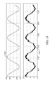
- Figure 12 illustrates a waveform chart of input signals achieved using the exemplary power factor correction algorithm shown in Figure 11 .
- the waveform chart includes AC line voltage 1200 and AC line current 1202 when motor controller 102 (shown in Figure 1 ) implements algorithm 1100.
- the harmonic control algorithm 1100 enables power factor correction using AC line current measurement with seventh harmonic injection.
- any order harmonic injection may be used that enables motor controller 102 to function as described herein.
- the seventh harmonic is either added or subtracted from the current reference I AC_fundamental *. This summation enables modification of the shape of the AC line current 1202 by injecting harmonics into the current wave form.
- the injected harmonics alter the wave form of AC line current 1202 such that its phase becomes close to being the phase of AC line voltage 1200, resulting in an increased power factor.
- the increased power factor is accomplished by sensing the AC input current, and controlling or reconstructing it using harmonic control to improve power flow from power source 108 to electric motor 104.
- Figure 13 is a flowchart 1300 of an exemplary method of controlling an electric motor using a motor controller.
- the method includes controlling 1302 an AC input current based on a DC link voltage measurement to improve a power factor of the electric motor.
- controlling the AC input current includes implementing 1304 an algorithm to determine a q-axis reference value based on the measured DC link voltage.
- determining the q-axis reference value includes measuring the DC link voltage using a voltage detector, processing the measured DC link voltage using a low-pass filter having a cut-off frequency lower than a switching frequency of said inverter and higher than twice the AC line frequency, phase shifting the processed DC link voltage, and multiplying the phase shifted voltage by a torque command.
- determining the q-axis reference value includes measuring the DC link voltage using a voltage detector, processing the measured DC link voltage using a phase detector, generating a sinusoidal-shaped waveform based on the measured phase, and multiplying the sinusoidal-shaped waveform by a torque command.
- controlling the AC input current includes implementing 1306 an algorithm to smooth the DC link voltage before generating a pulse width modulation (PWM) signal.
- PWM pulse width modulation
- controlling the AC input current includes implementing 1308 an algorithm to control a duty cycle of at least one voltage commanded by the controller.
- a technical effect of the systems and methods described herein includes at least one of: (a) controlling an AC input current based on a DC link voltage measurement to improve a power factor of the motor controller; (b) implementing an algorithm to determine a q-axis reference value based on the measured DC link voltage; (c) implementing an algorithm to smooth the DC link voltage before generating a PWM signal; and (d) implementing an algorithm to control a duty cycle of at least one voltage commanded by the controller.
- the embodiments described herein relate to electrical motor controllers and methods of operating the same. More particularly, the embodiments relate to a motor controller that eliminates large filter capacitors and provides a high power factor. More particularly, the embodiments relate to a motor controller configured to control AC input current based on based on a direct current (DC) link voltage measurement to facilitate improving a power factor of the motor controller.
- the size ranges disclosed herein include all the sub-ranges therebetween.
- the methods and systems are not limited to the specific embodiments described herein, but rather, components of systems and/or steps of the methods may be utilized independently and separately from other components and/or steps described herein. For example, the methods may also be used in combination with other manufacturing systems and methods, and are not limited to practice with only the systems and methods as described herein. Rather, the exemplary embodiment can be implemented and utilized in connection with many other electrical component applications.
Landscapes
- Engineering & Computer Science (AREA)
- Power Engineering (AREA)
- Control Of Ac Motors In General (AREA)
Applications Claiming Priority (1)
| Application Number | Priority Date | Filing Date | Title |
|---|---|---|---|
| US13/763,283 US9331614B2 (en) | 2013-02-08 | 2013-02-08 | Systems and methods for controlling electric machines |
Publications (2)
| Publication Number | Publication Date |
|---|---|
| EP2765703A2 true EP2765703A2 (de) | 2014-08-13 |
| EP2765703A3 EP2765703A3 (de) | 2017-10-25 |
Family
ID=50064504
Family Applications (1)
| Application Number | Title | Priority Date | Filing Date |
|---|---|---|---|
| EP14154308.2A Withdrawn EP2765703A3 (de) | 2013-02-08 | 2014-02-07 | System und Verfahren zur Steuerung elektrischer Maschinen |
Country Status (3)
| Country | Link |
|---|---|
| US (1) | US9331614B2 (de) |
| EP (1) | EP2765703A3 (de) |
| AU (1) | AU2013204711B2 (de) |
Cited By (4)
| Publication number | Priority date | Publication date | Assignee | Title |
|---|---|---|---|---|
| EP3139495A3 (de) * | 2015-08-24 | 2017-05-03 | Simmonds Precision Products, Inc. | Leistungsbegrenzung für motorstromsteuerungen |
| CN106655946A (zh) * | 2016-10-15 | 2017-05-10 | 青岛海尔空调器有限总公司 | 无电解电容电机驱动系统及其电流控制方法和控制装置 |
| EP3386096A1 (de) * | 2017-04-07 | 2018-10-10 | Black & Decker Inc. | Wellenformung in einer werkzeugmaschine mit wechselstromversorgung |
| WO2022101019A1 (de) * | 2020-11-10 | 2022-05-19 | Festool Gmbh | Elektrowerkzeug, verfahren, anordnung computerprogrammprodukt und computerlesbares medium |
Families Citing this family (22)
| Publication number | Priority date | Publication date | Assignee | Title |
|---|---|---|---|---|
| AU2015237427B2 (en) * | 2014-03-27 | 2017-09-07 | Daikin Industries, Ltd. | Power conversion device |
| JP6226833B2 (ja) * | 2014-07-30 | 2017-11-08 | 三菱電機株式会社 | 電力変換装置 |
| CN105634363B (zh) * | 2016-01-29 | 2018-03-20 | 东南大学 | 一种单相到三相逆变电机驱动系统的高输入功率因数控制方法 |
| US10305373B2 (en) | 2016-04-15 | 2019-05-28 | Emerson Climate Technologies, Inc. | Input reference signal generation systems and methods |
| US10312798B2 (en) | 2016-04-15 | 2019-06-04 | Emerson Electric Co. | Power factor correction circuits and methods including partial power factor correction operation for boost and buck power converters |
| US10656026B2 (en) | 2016-04-15 | 2020-05-19 | Emerson Climate Technologies, Inc. | Temperature sensing circuit for transmitting data across isolation barrier |
| US10284132B2 (en) | 2016-04-15 | 2019-05-07 | Emerson Climate Technologies, Inc. | Driver for high-frequency switching voltage converters |
| US10763740B2 (en) | 2016-04-15 | 2020-09-01 | Emerson Climate Technologies, Inc. | Switch off time control systems and methods |
| US9933842B2 (en) | 2016-04-15 | 2018-04-03 | Emerson Climate Technologies, Inc. | Microcontroller architecture for power factor correction converter |
| US10277115B2 (en) | 2016-04-15 | 2019-04-30 | Emerson Climate Technologies, Inc. | Filtering systems and methods for voltage control |
| ITUA20162878A1 (it) * | 2016-04-26 | 2017-10-26 | Phase Motion Control S P A | Dispositivo di alimentazione e azionamento per un motore elettrico a magneti permanenti |
| US10170976B2 (en) * | 2017-04-26 | 2019-01-01 | Delta Electronics (Thailand) Public Company, Limited | Phase compensation method for power factor correction circuit |
| US10295581B2 (en) | 2017-10-13 | 2019-05-21 | Deere & Company | Voltage sensor-less position detection in an active front end |
| US10270327B1 (en) * | 2017-10-13 | 2019-04-23 | Deere & Company | Voltage sensor-less position detection in an active front end |
| EP3599708A1 (de) * | 2018-07-26 | 2020-01-29 | Electrolux Appliances Aktiebolag | Wechselrichterbasierte vorrichtung und steuerungsverfahren dafür |
| CN109672343B (zh) * | 2018-12-17 | 2020-12-18 | 华为技术有限公司 | 一种接收端的相位校准电路、方法及接收端 |
| CN109900029B (zh) * | 2019-03-19 | 2021-05-28 | 海信(广东)空调有限公司 | 压缩机控制系统及其方法 |
| EP3866329B1 (de) * | 2020-02-12 | 2025-06-11 | Hamilton Sundstrand Corporation | Motorantrieb |
| EP3879687A1 (de) * | 2020-03-13 | 2021-09-15 | Hamilton Sundstrand Corporation | Estimierung der kapazität im dc zwischenkreis eines antriebssystems für einen elektromotor |
| JP7666901B2 (ja) * | 2020-07-20 | 2025-04-22 | 三星電子株式会社 | 電力変換装置及びその制御方法 |
| US12015353B1 (en) * | 2021-07-12 | 2024-06-18 | Smart Wires Inc. | Attenuating harmonic current in power transmission lines |
| CN116073706A (zh) * | 2021-11-01 | 2023-05-05 | 华润微集成电路(无锡)有限公司 | 自适应改变pwm占空比的方法、电路及电机驱动系统 |
Family Cites Families (13)
| Publication number | Priority date | Publication date | Assignee | Title |
|---|---|---|---|---|
| JP3699663B2 (ja) | 2001-05-24 | 2005-09-28 | 勲 高橋 | インバータ制御方法およびその装置 |
| JP3955286B2 (ja) | 2003-04-03 | 2007-08-08 | 松下電器産業株式会社 | モータ駆動用インバータ制御装置および空気調和機 |
| EP1617551A4 (de) | 2003-04-22 | 2010-09-08 | Panasonic Corp | Motorregeleinrichtung, kompressor, klimaanlage und kühlschrank |
| JP4561219B2 (ja) | 2003-10-03 | 2010-10-13 | パナソニック株式会社 | モータ駆動用インバータ制御装置およびそれを用いた空気調和機 |
| JP5161766B2 (ja) | 2006-04-24 | 2013-03-13 | パナソニック株式会社 | インバータ装置および空気調和機 |
| US7683568B2 (en) * | 2007-09-28 | 2010-03-23 | Rockwell Automation Technologies, Inc. | Motor drive using flux adjustment to control power factor |
| JP5365058B2 (ja) * | 2008-04-18 | 2013-12-11 | ダイキン工業株式会社 | コンバータの制御方法 |
| US7986538B2 (en) * | 2008-06-03 | 2011-07-26 | Hamilton Sundstrand Corporation | Midpoint current and voltage regulation of a multi-level converter |
| JP5549384B2 (ja) * | 2010-06-03 | 2014-07-16 | 日産自動車株式会社 | 電動機の制御装置および電動機制御システム |
| JP5212491B2 (ja) | 2011-01-18 | 2013-06-19 | ダイキン工業株式会社 | 電力変換装置 |
| US20130088903A1 (en) * | 2011-10-11 | 2013-04-11 | Hamilton Sundstrand Corporation | Control architecture for a multi-level active rectifier |
| KR101928435B1 (ko) * | 2012-06-19 | 2018-12-12 | 삼성전자주식회사 | 전력 변환 장치 및 이의 제어 방법 |
| US20140119074A1 (en) * | 2012-10-31 | 2014-05-01 | Christopher J. Courtney | Operation of multichannel active rectifier |
-
2013
- 2013-02-08 US US13/763,283 patent/US9331614B2/en active Active
- 2013-04-12 AU AU2013204711A patent/AU2013204711B2/en not_active Ceased
-
2014
- 2014-02-07 EP EP14154308.2A patent/EP2765703A3/de not_active Withdrawn
Non-Patent Citations (1)
| Title |
|---|
| None |
Cited By (7)
| Publication number | Priority date | Publication date | Assignee | Title |
|---|---|---|---|---|
| EP3139495A3 (de) * | 2015-08-24 | 2017-05-03 | Simmonds Precision Products, Inc. | Leistungsbegrenzung für motorstromsteuerungen |
| CN106655946A (zh) * | 2016-10-15 | 2017-05-10 | 青岛海尔空调器有限总公司 | 无电解电容电机驱动系统及其电流控制方法和控制装置 |
| CN106655946B (zh) * | 2016-10-15 | 2019-07-26 | 青岛海尔空调器有限总公司 | 无电解电容电机驱动系统及其电流控制方法和控制装置 |
| EP3386096A1 (de) * | 2017-04-07 | 2018-10-10 | Black & Decker Inc. | Wellenformung in einer werkzeugmaschine mit wechselstromversorgung |
| US10710220B2 (en) | 2017-04-07 | 2020-07-14 | Black & Decker Inc. | Waveform shaping in power tool powered by alternating-current power supply |
| WO2022101019A1 (de) * | 2020-11-10 | 2022-05-19 | Festool Gmbh | Elektrowerkzeug, verfahren, anordnung computerprogrammprodukt und computerlesbares medium |
| US12381500B2 (en) | 2020-11-10 | 2025-08-05 | Festool Gmbh | Electric tool, method, assembly, computer program product, and computer readable medium |
Also Published As
| Publication number | Publication date |
|---|---|
| AU2013204711B2 (en) | 2015-09-03 |
| US9331614B2 (en) | 2016-05-03 |
| AU2013204711A1 (en) | 2014-08-28 |
| US20140225545A1 (en) | 2014-08-14 |
| EP2765703A3 (de) | 2017-10-25 |
Similar Documents
| Publication | Publication Date | Title |
|---|---|---|
| US9331614B2 (en) | Systems and methods for controlling electric machines | |
| RU2462806C1 (ru) | Устройство преобразования электроэнергии | |
| JP6132948B1 (ja) | モータ制御装置およびモータ制御方法 | |
| US11218107B2 (en) | Control device for power converter | |
| KR101995864B1 (ko) | 인버터 제어장치 및 그 제어방법 | |
| KR101594662B1 (ko) | 전력 변환 장치 | |
| US20160352269A1 (en) | Apparatus for controlling rotary electric machine | |
| EP2763309A2 (de) | Umrichtervorrichtung und Verfahren zur Steuerung einer Umrichtervorrichtung | |
| US12355379B2 (en) | Power conversion system | |
| CN109546913A (zh) | 一种电容小型化电机驱动装置 | |
| JP2010284017A (ja) | 交流電動機の制御装置 | |
| CN108809177B (zh) | 无电解电容电机驱动方法、装置、电子设备及存储介质 | |
| JP5888074B2 (ja) | 電力変換装置 | |
| JP5196269B2 (ja) | 電動機の制御装置 | |
| Son et al. | Grid current shaping of single phase diode rectifier with small DC-link capacitor for three phase motor drive | |
| JP6729249B2 (ja) | 電力変換器の制御装置 | |
| JP5990970B2 (ja) | モータ駆動装置 | |
| AU2019309255A1 (en) | Inverter based apparatus and control method thereof |
Legal Events
| Date | Code | Title | Description |
|---|---|---|---|
| PUAI | Public reference made under article 153(3) epc to a published international application that has entered the european phase |
Free format text: ORIGINAL CODE: 0009012 |
|
| 17P | Request for examination filed |
Effective date: 20140207 |
|
| AK | Designated contracting states |
Kind code of ref document: A2 Designated state(s): AL AT BE BG CH CY CZ DE DK EE ES FI FR GB GR HR HU IE IS IT LI LT LU LV MC MK MT NL NO PL PT RO RS SE SI SK SM TR |
|
| AX | Request for extension of the european patent |
Extension state: BA ME |
|
| PUAL | Search report despatched |
Free format text: ORIGINAL CODE: 0009013 |
|
| AK | Designated contracting states |
Kind code of ref document: A3 Designated state(s): AL AT BE BG CH CY CZ DE DK EE ES FI FR GB GR HR HU IE IS IT LI LT LU LV MC MK MT NL NO PL PT RO RS SE SI SK SM TR |
|
| AX | Request for extension of the european patent |
Extension state: BA ME |
|
| RIC1 | Information provided on ipc code assigned before grant |
Ipc: H02P 23/00 20160101AFI20170919BHEP Ipc: H02P 6/14 20160101ALI20170919BHEP |
|
| STAA | Information on the status of an ep patent application or granted ep patent |
Free format text: STATUS: REQUEST FOR EXAMINATION WAS MADE |
|
| R17P | Request for examination filed (corrected) |
Effective date: 20180425 |
|
| RBV | Designated contracting states (corrected) |
Designated state(s): AL AT BE BG CH CY CZ DE DK EE ES FI FR GB GR HR HU IE IS IT LI LT LU LV MC MK MT NL NO PL PT RO RS SE SI SK SM TR |
|
| STAA | Information on the status of an ep patent application or granted ep patent |
Free format text: STATUS: EXAMINATION IS IN PROGRESS |
|
| 17Q | First examination report despatched |
Effective date: 20200430 |
|
| REG | Reference to a national code |
Ref country code: DE Ref legal event code: R079 Free format text: PREVIOUS MAIN CLASS: H02P0023000000 Ipc: H02P0023260000 |
|
| GRAP | Despatch of communication of intention to grant a patent |
Free format text: ORIGINAL CODE: EPIDOSNIGR1 |
|
| STAA | Information on the status of an ep patent application or granted ep patent |
Free format text: STATUS: GRANT OF PATENT IS INTENDED |
|
| RIC1 | Information provided on ipc code assigned before grant |
Ipc: H02P 23/26 20160101AFI20230928BHEP |
|
| INTG | Intention to grant announced |
Effective date: 20231020 |
|
| STAA | Information on the status of an ep patent application or granted ep patent |
Free format text: STATUS: THE APPLICATION IS DEEMED TO BE WITHDRAWN |
|
| 18D | Application deemed to be withdrawn |
Effective date: 20240301 |