EP2764958A1 - Gelenkmechanismus und Roboter - Google Patents
Gelenkmechanismus und Roboter Download PDFInfo
- Publication number
- EP2764958A1 EP2764958A1 EP14154062.5A EP14154062A EP2764958A1 EP 2764958 A1 EP2764958 A1 EP 2764958A1 EP 14154062 A EP14154062 A EP 14154062A EP 2764958 A1 EP2764958 A1 EP 2764958A1
- Authority
- EP
- European Patent Office
- Prior art keywords
- screw
- motor
- input shaft
- shaped input
- wrist
- Prior art date
- Legal status (The legal status is an assumption and is not a legal conclusion. Google has not performed a legal analysis and makes no representation as to the accuracy of the status listed.)
- Withdrawn
Links
- 230000007246 mechanism Effects 0.000 title claims abstract description 31
- 239000003638 chemical reducing agent Substances 0.000 claims abstract description 26
- 210000000707 wrist Anatomy 0.000 claims description 47
- 238000009434 installation Methods 0.000 description 3
- 230000004075 alteration Effects 0.000 description 1
- 238000012986 modification Methods 0.000 description 1
- 230000004048 modification Effects 0.000 description 1
- 238000005549 size reduction Methods 0.000 description 1
Images

Classifications
-
- B—PERFORMING OPERATIONS; TRANSPORTING
- B25—HAND TOOLS; PORTABLE POWER-DRIVEN TOOLS; MANIPULATORS
- B25J—MANIPULATORS; CHAMBERS PROVIDED WITH MANIPULATION DEVICES
- B25J17/00—Joints
-
- B—PERFORMING OPERATIONS; TRANSPORTING
- B25—HAND TOOLS; PORTABLE POWER-DRIVEN TOOLS; MANIPULATORS
- B25J—MANIPULATORS; CHAMBERS PROVIDED WITH MANIPULATION DEVICES
- B25J9/00—Programme-controlled manipulators
- B25J9/10—Programme-controlled manipulators characterised by positioning means for manipulator elements
- B25J9/102—Gears specially adapted therefor, e.g. reduction gears
-
- Y—GENERAL TAGGING OF NEW TECHNOLOGICAL DEVELOPMENTS; GENERAL TAGGING OF CROSS-SECTIONAL TECHNOLOGIES SPANNING OVER SEVERAL SECTIONS OF THE IPC; TECHNICAL SUBJECTS COVERED BY FORMER USPC CROSS-REFERENCE ART COLLECTIONS [XRACs] AND DIGESTS
- Y10—TECHNICAL SUBJECTS COVERED BY FORMER USPC
- Y10S—TECHNICAL SUBJECTS COVERED BY FORMER USPC CROSS-REFERENCE ART COLLECTIONS [XRACs] AND DIGESTS
- Y10S901/00—Robots
- Y10S901/27—Arm part
- Y10S901/28—Joint
-
- Y—GENERAL TAGGING OF NEW TECHNOLOGICAL DEVELOPMENTS; GENERAL TAGGING OF CROSS-SECTIONAL TECHNOLOGIES SPANNING OVER SEVERAL SECTIONS OF THE IPC; TECHNICAL SUBJECTS COVERED BY FORMER USPC CROSS-REFERENCE ART COLLECTIONS [XRACs] AND DIGESTS
- Y10—TECHNICAL SUBJECTS COVERED BY FORMER USPC
- Y10T—TECHNICAL SUBJECTS COVERED BY FORMER US CLASSIFICATION
- Y10T74/00—Machine element or mechanism
- Y10T74/20—Control lever and linkage systems
- Y10T74/20207—Multiple controlling elements for single controlled element
- Y10T74/20305—Robotic arm
- Y10T74/20329—Joint between elements
Definitions
- An embodiment disclosed herein relates to a joint mechanism and a robot.
- a robot including an arm unit and a wrist unit in which links are rotatably connected to each other.
- the shafts of the links are made hollow such that a cable or the like can be arranged within the arm unit.
- joint mechanisms for rotatably interconnecting the hollow shafts there is known a joint mechanism in which bevel gears are used as a power delivery mechanism for delivering the power of a motor (see, e.g., Japanese Patent Application Publication No. H08-229874 ).
- an embodiment disclosed herein provides a joint mechanism and a robot which are capable of sufficiently increasing the diameters of hollow portions of links having hollow shafts and capable of reducing a backlash.
- a joint mechanism including: a motor including a motor shaft and a hypoid pinion provided at a tip end of the motor shaft; and a speed reducer configured to reduce a rotation speed of the motor at a speed reduction ratio.
- the speed reducer includes a screw-shaped input shaft and a ring-shaped gear meshing with the screw-shaped input shaft and three-dimensionally intersecting the screw-shaped input shaft at a right angle
- the screw-shaped input shaft includes a shaft body provided with a screw portion and a hypoid gear arranged at one end of the screw-shaped input shaft and configured to mesh with the hypoid pinion
- the screw-shaped input shaft has an axis three-dimensionally intersecting the motor shaft at a right angle.
- an X-axis and a Y-axis orthogonal to each other are defined as being parallel to an installation surface (e.g., a horizontal surface) on which the robot 1 is installed.
- a Z-axis is defined as being normal to the installation surface.
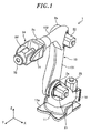
- the robot 1 is, e.g., an articulated robot. As shown in Fig. 1 , the robot 1 includes a base 11, a body unit 12 arranged on the base 11, an arm unit 13 connected to the body unit 12 and a wrist unit 14 arranged at the tip end of the arm unit 13.
- the base 11 is fixed to an installation surface through a seat portion 11a.
- the body unit 12 is arranged on the base 11 to horizontally rotate about a vertical axis (the Z-axis in Fig. 1 ).
- the body unit 12 is horizontally rotated by the operation of a motor unit 20.
- the arm unit 13 connected to the body unit 12 includes a first arm 131 and a second arm 132 as a plurality of links.
- the first arm 131 and the second arm 132 are rotatably connected to each other by a joint unit.
- the first arm 131 is connected to the body unit 12 through a first joint unit 2a to swing in the front-rear direction (the Y-direction).
- the second arm 132 is connected to the tip end portion of the first arm 131 through a second joint unit 2b to swing in the up-down direction (the Z-direction).
- the first joint unit 2a for swinging the first arm 131 is provided with a first motor unit 21.
- the second joint unit 2b for swinging the second arm 132 is provided with a second motor unit 22.
- the wrist unit 14 includes a first wrist 71 and a second wrist 72 as a plurality of links.
- the first wrist 71 and the second wrist 72 are rotatably connected to each other by a joint unit.
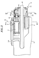
- a wrist frame 710 of the first wrist 71 includes a base end portion connected to the tip end of the second arm 132 of the arm unit 13 through a third joint unit 2c to rotate about its rotation axis and a tip end portion formed into a bifurcated shape.
- a cable 8 or the like is arranged within the wrist frame 710 (see Figs. 2 and 3 ).
- An additional cable 80 including a hose or the like extends through a central space of the first wrist 71 along the longitudinal direction of the second arm 132. Then, the cable 80 or the like passes through a below-mentioned hollow portion 53 of the second wrist 72 ( Figs. 2 to 4 ).
- the second wrist 72 is formed into a substantially cylindrical shape and is connected to the tip end portion of the bifurcated wrist frame 710 of the first wrist 71 to swing about a swing axis (e.g., in the Z-direction in Fig. 1 ) by a fourth joint unit 2d.
- the second wrist 72 rotates about its rotation axis by a fifth joint unit 2e arranged therein.
- the fourth joint unit 2d includes a speed reducing mechanism 9 arranged in the second wrist 72, a swinging motor (not shown) and a power delivery mechanism.
- the swinging motor can be installed at the base end of the bifurcated portion of the first wrist 71 and is operatively connected to the speed reducing mechanism 9 through the power delivery mechanism such as a drive shaft, a gear mechanism or a belt mechanism.
- the second wrist 72 is connected to the first wrist 71 and rotates about its rotation axis by the fifth joint unit 2e.
- the fifth joint unit 2e is arranged within the second wrist 72 as a driven member.
- the joint mechanism 3 in accordance with the present embodiment is installed in the fifth joint unit 2e.
- the joint mechanism 3 installed in the fifth joint unit 2e includes a motor 4 and a speed reducer 5 for reducing the rotation speed of the motor 4 at a predetermined speed reduction ratio.
- the motor 4 is installed to extend along the longitudinal direction of the wrist unit 14 and is arranged inside the bifurcated tip end portion of the wrist frame 710.
- the motor 4 includes a motor shaft 41 supported by a bearing 42.
- the motor shaft 41 extends toward the second wrist 72.
- the motor shaft 41 is provided with a hypoid pinion 61 at the tip end thereof.
- a body unit of the motor 4 has a general structure which includes a stator fixed to an inner surface of a case and a rotor rotatably installed with a specified gap left between the rotor and the stator.
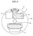
- the speed reducer 5 operatively connected to the motor 4 is formed into a hollow structure having a hollow portion 53. More specifically, the speed reducer 5 includes a ring-shaped gear 52 provided with a plurality of cam followers 52a corresponding to gear teeth arranged in the outer periphery of the ring-shaped gear 52 and a screw-shaped input shaft 51 configured to deliver the power of the motor 4 to the ring-shaped gear 52.
- the screw-shaped input shaft 51 includes a shaft body 51b and a screw portion 51a formed on the shaft body 51b.
- the screw portion 51a serves as a cam member which moves the cam followers 52a to rotate the ring-shaped gear 52 about its own axis.
- a hypoid gear 62 is arranged at one end of the screw-shaped input shaft 51.
- the hypoid gear 62 meshes with the hypoid pinion 61 arranged in the motor shaft 41.
- the screw-shaped input shaft 51 has an axis A which three-dimensionally intersects the motor shaft 41 at a right angle.
- the speed reducer 5 is arranged such that the motor shaft 41 is positioned closer to the ring-shaped gear 52 than the center of the screw-shaped input shaft 51 and such that the axis of the screw-shaped input shaft 51 three-dimensionally intersects the motor shaft 41 at a right angle. Accordingly, as shown in Fig. 4 , the screw-shaped input shaft 51 and the motor shaft 41 are offset by a distance D, and the motor 4 can be offset by the distance D closer to the hollow portion 53 of the speed reducer 5.
- the motor 4 can be arranged as close to the wrist frame 710 as possible without protruding from a desired region 100.
- the region 100 is, e.g., a circular region which accommodates the outermost periphery of the wrist unit 14 and which has a specified diameter.
- the axis of the hollow portion 53 three-dimensionally intersects the screw-shaped input shaft 51 at a right angle.
- the screw-shaped input shaft 51 and the ring-shaped gear 52 have a configuration like a worm gear.
- the screw-shaped input shaft 51 corresponds to a worm and the ring-shaped gear 52 corresponds to a worm wheel.
- the rotation of the motor 4 is delivered to the speed reducer 5. Accordingly, the second wrist 72 rotates about its rotation axis with the speed thereof reduced at a predetermined speed reduction ratio. Specifically, the rotation of the motor 4 is delivered from the motor shaft 41 to the hypoid pinion 61, the hypoid gear 62, the screw-shaped input shaft 51 and then the ring-shaped gear 52. Thus, the second wrist 72 rotates about its rotation axis. In this way, the input route of the power of the motor 4 to the second wrist 72 is changed at two stages by the hypoid pinion 61 and the hypoid gear 62 and by the screw-shaped input shaft 51 and the ring-shaped gear 52.
- the speed reducer 5 is provided with the ring-shaped gear 52 having the hollow portion 53. For that reason, if the speed reducer 5 is disposed at the tip end of the wrist unit 14 of the robot 1, it becomes possible to obtain a sufficient diameter of the hollow portion (the hollow bore) while maintaining the positioning accuracy of the axis of the wrist unit 14.
- the members corresponding to the gear teeth meshing with the screw-shaped input shaft 51 are formed of the cam followers 52a. For that reason, it is possible for the ring-shaped gear 52 to suppress generation of a backlash as far as possible. Accordingly, the robot 1 can realize precise and accurate motion of the wrist unit 14.
- the joint mechanism 3 in accordance with the present embodiment is installed in the rotating link, e.g., the second wrist 72. More specifically, the rotation of the motor 4 is inputted through the hypoid pinion 61 attached to the tip end of the motor shaft 41 and the hypoid gear 62 attached to the screw-shaped input shaft 51 serving as an input shaft of the speed reducer 5.
- the rotation of the motor 4 is delivered to the speed reducer 5 with the speed thereof first reduced by the hypoid pinion 61 and the hypoid gear 62.
- the speed reducer 5 can be arranged within the second wrist 72, which makes it possible to reduce the size of the wrist unit 14 of the robot 1.
- the direction of the screw-shaped input shaft 51 of the speed reducer 5 can be changed to a direction perpendicular to the motor shaft 41. Accordingly, as shown in Fig. 2 , it is possible to dispose the motor 4 along the longitudinal direction of the wrist unit 14 and to install the speed reducer 5 within the second wrist 72. This makes it possible to further reduce the size of the wrist unit 14 of the robot 1.
- the motor 4 can be disposed adjacent to the second wrist 72, it is possible to directly deliver the power of the motor 4 from the motor shaft 41 to the speed reducer 5. Therefore, there is no need to install a drive shaft or other drive gears between the motor 4 and the speed reducer 5. This can make contribution to the reduction of the number of parts and the reduction of weight.
- the joint mechanism 3 is used in driving the second wrist 72 of the wrist unit 14.
- the joint mechanism 3 according to the present embodiment may be applied to, e.g., the second joint unit 2b shown in Fig. 1 .
- the second arm 132 is formed into a hollow structure, it is possible to secure a hollow bore communicating with the hollow structure and to dispose a cable or the like within the second arm 132.
Applications Claiming Priority (1)
| Application Number | Priority Date | Filing Date | Title |
|---|---|---|---|
| JP2013024958A JP5655877B2 (ja) | 2013-02-12 | 2013-02-12 | 関節機構およびロボット |
Publications (1)
| Publication Number | Publication Date |
|---|---|
| EP2764958A1 true EP2764958A1 (de) | 2014-08-13 |
Family
ID=50101699
Family Applications (1)
| Application Number | Title | Priority Date | Filing Date |
|---|---|---|---|
| EP14154062.5A Withdrawn EP2764958A1 (de) | 2013-02-12 | 2014-02-06 | Gelenkmechanismus und Roboter |
Country Status (6)
| Country | Link |
|---|---|
| US (1) | US20140224058A1 (de) |
| EP (1) | EP2764958A1 (de) |
| JP (1) | JP5655877B2 (de) |
| KR (1) | KR20140101680A (de) |
| CN (1) | CN103978494A (de) |
| IN (1) | IN2014CH00635A (de) |
Cited By (1)
| Publication number | Priority date | Publication date | Assignee | Title |
|---|---|---|---|---|
| US10710251B2 (en) | 2016-04-07 | 2020-07-14 | Fanuc Corporation | Robot linear object handling structure |
Families Citing this family (5)
| Publication number | Priority date | Publication date | Assignee | Title |
|---|---|---|---|---|
| FR2929875B1 (fr) * | 2008-04-09 | 2012-01-13 | Aldebaran Robotics | Articulation motorisee a deux liaisons pivots et robots humanoide mettant en oeuvre l'articulation |
| JP5434991B2 (ja) * | 2011-09-01 | 2014-03-05 | 株式会社安川電機 | ロボット |
| JP6443456B2 (ja) | 2014-11-26 | 2018-12-26 | 株式会社安川電機 | ロボットアーム、ロボットシステム |
| NO344795B1 (no) * | 2018-10-17 | 2020-04-27 | Conrobotix As | Anordning ved robot, spesielt innrettet for bygg- og anleggsvirksomhet |
| CN110246293A (zh) * | 2019-06-29 | 2019-09-17 | 南京奥灵克物联网科技有限公司 | 一种安防监控设备及安装管理方法 |
Citations (6)
| Publication number | Priority date | Publication date | Assignee | Title |
|---|---|---|---|---|
| JPH08229874A (ja) | 1995-02-21 | 1996-09-10 | Kobe Steel Ltd | 産業用ロボットの手首装置 |
| US20030090115A1 (en) * | 2001-11-09 | 2003-05-15 | Korea Institute Of Science And Technology | Robot hand and robot hand finger |
| US20100036507A1 (en) * | 2005-11-29 | 2010-02-11 | David James Gow | Prostheses With Mechanically Operable Digit Members |
| CN101850796A (zh) * | 2010-01-07 | 2010-10-06 | 郑州轻工业学院 | 可组合的机器人关节构成的四肢单元 |
| US20120067150A1 (en) * | 2010-09-16 | 2012-03-22 | Hon Hai Precision Industry Co., Ltd. | Robotic arm assembly |
| WO2012075736A1 (zh) * | 2010-12-07 | 2012-06-14 | 配天(安徽)电子技术有限公司 | 蜗杆减速器、机器人关节及机器人 |
Family Cites Families (12)
| Publication number | Priority date | Publication date | Assignee | Title |
|---|---|---|---|---|
| US4822238A (en) * | 1986-06-19 | 1989-04-18 | Westinghouse Electric Corp. | Robotic arm |
| JPS63156682A (ja) * | 1986-12-19 | 1988-06-29 | 株式会社日立製作所 | ロボツト |
| US4957320A (en) * | 1988-08-31 | 1990-09-18 | Trustees Of The University Of Pennsylvania | Methods and apparatus for mechanically intelligent grasping |
| SE502608C2 (sv) * | 1994-05-13 | 1995-11-20 | Asea Brown Boveri | Drivenhet för industrirobot |
| US5992259A (en) * | 1996-10-16 | 1999-11-30 | Fleytman; Yakov | Worm/wormgear transmission and apparatus for transmitting rotation utilizing an oscillating input |
| JP3636104B2 (ja) * | 2001-06-28 | 2005-04-06 | 高広工業株式会社 | 回転伝達装置、それに用いられる歯付回転体および回転伝達装置の製造方法 |
| JP2007229874A (ja) * | 2006-03-01 | 2007-09-13 | Kawasaki Heavy Ind Ltd | 産業用ロボット |
| JP4233578B2 (ja) * | 2006-08-10 | 2009-03-04 | ファナック株式会社 | 産業用ロボットの手首駆動構造 |
| EP2093027B1 (de) * | 2006-12-07 | 2011-02-09 | Panasonic Corporation | Gelenkmechanismus |
| JP2010046773A (ja) * | 2008-08-22 | 2010-03-04 | Sankyo Mfg Co Ltd | 物品搬送用垂直多関節アーム機構 |
| US8474347B2 (en) * | 2009-06-08 | 2013-07-02 | Hub City, Inc. | High efficiency right angle gearbox |
| JP5434991B2 (ja) * | 2011-09-01 | 2014-03-05 | 株式会社安川電機 | ロボット |
-
2013
- 2013-02-12 JP JP2013024958A patent/JP5655877B2/ja not_active Expired - Fee Related
-
2014
- 2014-02-06 EP EP14154062.5A patent/EP2764958A1/de not_active Withdrawn
- 2014-02-07 KR KR1020140014290A patent/KR20140101680A/ko not_active Application Discontinuation
- 2014-02-11 CN CN201410047323.6A patent/CN103978494A/zh active Pending
- 2014-02-11 US US14/178,177 patent/US20140224058A1/en not_active Abandoned
- 2014-02-11 IN IN635CH2014 patent/IN2014CH00635A/en unknown
Patent Citations (6)
| Publication number | Priority date | Publication date | Assignee | Title |
|---|---|---|---|---|
| JPH08229874A (ja) | 1995-02-21 | 1996-09-10 | Kobe Steel Ltd | 産業用ロボットの手首装置 |
| US20030090115A1 (en) * | 2001-11-09 | 2003-05-15 | Korea Institute Of Science And Technology | Robot hand and robot hand finger |
| US20100036507A1 (en) * | 2005-11-29 | 2010-02-11 | David James Gow | Prostheses With Mechanically Operable Digit Members |
| CN101850796A (zh) * | 2010-01-07 | 2010-10-06 | 郑州轻工业学院 | 可组合的机器人关节构成的四肢单元 |
| US20120067150A1 (en) * | 2010-09-16 | 2012-03-22 | Hon Hai Precision Industry Co., Ltd. | Robotic arm assembly |
| WO2012075736A1 (zh) * | 2010-12-07 | 2012-06-14 | 配天(安徽)电子技术有限公司 | 蜗杆减速器、机器人关节及机器人 |
Cited By (1)
| Publication number | Priority date | Publication date | Assignee | Title |
|---|---|---|---|---|
| US10710251B2 (en) | 2016-04-07 | 2020-07-14 | Fanuc Corporation | Robot linear object handling structure |
Also Published As
| Publication number | Publication date |
|---|---|
| US20140224058A1 (en) | 2014-08-14 |
| JP5655877B2 (ja) | 2015-01-21 |
| JP2014151413A (ja) | 2014-08-25 |
| KR20140101680A (ko) | 2014-08-20 |
| IN2014CH00635A (de) | 2015-04-24 |
| CN103978494A (zh) | 2014-08-13 |
Similar Documents
| Publication | Publication Date | Title |
|---|---|---|
| EP2764958A1 (de) | Gelenkmechanismus und Roboter | |
| EP2764959A1 (de) | Gelenkmechanismus und Roboter | |
| US9095982B2 (en) | Drive apparatus and robot | |
| JP5746093B2 (ja) | 産業用ロボットの手首装置 | |
| EP3343067B1 (de) | Multidirektionale antriebsvorrichtung und automatische kamera | |
| EP3540265A1 (de) | Multidirektionale antriebsvorrichtung, robotergelenkmechanismus und multidirektionales antriebsverfahren | |
| JP2017185574A (ja) | ロボットアーム | |
| JP6438193B2 (ja) | 多関節ロボットの手首構造 | |
| EP3358217B1 (de) | Drehzahlminderer | |
| JP2010014177A (ja) | 偏心揺動型歯車伝動装置 | |
| JP6061022B2 (ja) | 複合駆動装置およびロボット | |
| JP5989148B2 (ja) | 減速機、及びこれを具えた直交型ギアモータ | |
| JP2019158142A (ja) | 歯車ユニット | |
| JP7268491B2 (ja) | ロボット | |
| US20230249364A1 (en) | Arm structure of industrial robot | |
| JP6807076B2 (ja) | ロボットの減速伝達装置 | |
| JP2016003754A (ja) | 減速機、ロボットおよびロボットシステム | |
| JP7075133B2 (ja) | 動力伝達装置及び口腔内加工装置 | |
| US10759047B1 (en) | Speed reducer and robot | |
| CN203449325U (zh) | 机器人臂 | |
| JP2021536558A (ja) | 機械式減速機とそれを用いたギヤードモータ | |
| CN111376309A (zh) | 齿轮机构、齿轮调整方法以及机器人 | |
| CN105751241A (zh) | 机器人臂 | |
| JP2016075349A (ja) | 減速機及びロボット |
Legal Events
| Date | Code | Title | Description |
|---|---|---|---|
| PUAI | Public reference made under article 153(3) epc to a published international application that has entered the european phase |
Free format text: ORIGINAL CODE: 0009012 |
|
| 17P | Request for examination filed |
Effective date: 20140206 |
|
| AK | Designated contracting states |
Kind code of ref document: A1 Designated state(s): AL AT BE BG CH CY CZ DE DK EE ES FI FR GB GR HR HU IE IS IT LI LT LU LV MC MK MT NL NO PL PT RO RS SE SI SK SM TR |
|
| AX | Request for extension of the european patent |
Extension state: BA ME |
|
| R17P | Request for examination filed (corrected) |
Effective date: 20150202 |
|
| RBV | Designated contracting states (corrected) |
Designated state(s): AL AT BE BG CH CY CZ DE DK EE ES FI FR GB GR HR HU IE IS IT LI LT LU LV MC MK MT NL NO PL PT RO RS SE SI SK SM TR |
|
| STAA | Information on the status of an ep patent application or granted ep patent |
Free format text: STATUS: THE APPLICATION IS DEEMED TO BE WITHDRAWN |
|
| 18D | Application deemed to be withdrawn |
Effective date: 20160901 |