EP2764808A1 - Mahlwerk - Google Patents
Mahlwerk Download PDFInfo
- Publication number
- EP2764808A1 EP2764808A1 EP14405005.1A EP14405005A EP2764808A1 EP 2764808 A1 EP2764808 A1 EP 2764808A1 EP 14405005 A EP14405005 A EP 14405005A EP 2764808 A1 EP2764808 A1 EP 2764808A1
- Authority
- EP
- European Patent Office
- Prior art keywords
- grinder
- grinding
- coffee powder
- mitnehmerrad
- edge
- Prior art date
- Legal status (The legal status is an assumption and is not a legal conclusion. Google has not performed a legal analysis and makes no representation as to the accuracy of the status listed.)
- Granted
Links
Images

Classifications
-
- A—HUMAN NECESSITIES
- A47—FURNITURE; DOMESTIC ARTICLES OR APPLIANCES; COFFEE MILLS; SPICE MILLS; SUCTION CLEANERS IN GENERAL
- A47J—KITCHEN EQUIPMENT; COFFEE MILLS; SPICE MILLS; APPARATUS FOR MAKING BEVERAGES
- A47J42/00—Coffee mills; Spice mills
- A47J42/38—Parts or details
- A47J42/40—Parts or details relating to discharge, receiving container or the like; Bag clamps, e.g. with means for actuating electric switches
-
- A—HUMAN NECESSITIES
- A47—FURNITURE; DOMESTIC ARTICLES OR APPLIANCES; COFFEE MILLS; SPICE MILLS; SUCTION CLEANERS IN GENERAL
- A47J—KITCHEN EQUIPMENT; COFFEE MILLS; SPICE MILLS; APPARATUS FOR MAKING BEVERAGES
- A47J42/00—Coffee mills; Spice mills
- A47J42/02—Coffee mills; Spice mills having grinding cones
- A47J42/06—Coffee mills; Spice mills having grinding cones mechanically driven
-
- A—HUMAN NECESSITIES
- A47—FURNITURE; DOMESTIC ARTICLES OR APPLIANCES; COFFEE MILLS; SPICE MILLS; SUCTION CLEANERS IN GENERAL
- A47J—KITCHEN EQUIPMENT; COFFEE MILLS; SPICE MILLS; APPARATUS FOR MAKING BEVERAGES
- A47J42/00—Coffee mills; Spice mills
- A47J42/02—Coffee mills; Spice mills having grinding cones
- A47J42/10—Grinding cones
Definitions
- the invention relates to a grinder, which is used for grinding coffee beans.
- Such a grinder is usually provided in combination with an automatic coffee machine, but can also be used alone.
- a Mitauerrad may have at the top of a about the axis of rotation of the Mit psychologyrades extending area (hereinafter "transport area"), on which the ground by the grinder coffee powder can fall.
- transport area the transport area of the driving wheel
- the driving wheel In order for the coffee powder ground by the grinding device to fall onto the transport area of the driving wheel, the driving wheel must be arranged correspondingly relative to the grinding device.
- grinders are known with a Mit supportiverad which is conical (see EP-A-1964498 . Fig. 1 ).
- a Mit supportiverad also called "Austragsteller”
- the transport of this Mit supportiverades is slightly conical, ie flat radially outwardly linear sloping. Due to the rotation of the driving wheel, coffee powder located on the transport area is, on the one hand, moved about the axis of rotation of the driving wheel and, on the other hand, moved radially outwards by a centrifugal force. Since the transport area is slightly linearly sloping, the radially outward movement is additionally supported.
- Known driving wheels can have a plurality of driving wings, which are arranged on the upper side of the driving wheel in the transport area and extend radially to the axis of rotation. These driver wings promote ground coffee powder in a rotation of the Mit predominantlyrades in the direction of rotation, ie. along a path around the axis of rotation.
- Out DE-A-441 813 are driving wings ("Winderiel 21" according to Fig. 3 ), which are arranged on the outer edge of the Mit psychologyrades (9) and over a relatively short distance extend (compared to the width of the transport area) of the Mit psychologyrades.
- the disadvantage is that the coffee powder is not very efficiently transported by means of this driver wing around the axis of rotation, but rather swirled. Falling on the Mitauerrad powder remains during several revolutions of the Mit predominantlyrades in the transport area before it reaches the outlet channel, and thus results in a low flow rate.
- the present invention has for its object to avoid the disadvantages mentioned, and to provide a grinder in which the ground coffee powder is quickly and completely transported to the outlet channel.
- the grinder according to the invention which serves for grinding coffee beans, is provided with a first grinding element and a second grinding element, wherein the two grinding elements are rotatable relative to each other such that coffee beans are ground by the grinding elements to a coffee powder. Furthermore, a rotatable with the first grinding element Mit Meetingrad is provided, which serves on his Edge area to pass the ground coffee powder through an outlet channel out of the grinder addition.
- the edge region of the Mit Anlagenrades is tapered to the refining elements formed with a concave profile such that an inner high edge and an outer lower edge are formed, and the Mitauerrad has a plurality of distributed in the edge region over the circumference driver wing.
- the inventive grinder has the great advantage that it is very compact and has an improved capacity compared to conventional grinders.
- the special design of the Mit Anlagenrades with the driver wings causes ground coffee powder is very quickly transported from the grinding device in the outlet channel. Furthermore, the residual amount of coffee powder - i. the ground coffee powder remaining after completing a grinding process on the driving wheel and in the outlet channel - much lower.
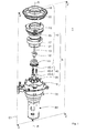
- FIG. 1 is shown (in perspective and in exploded view) a grinder 1 for grinding coffee beans, which consists of a grinding device 5 with a gear 70 and a drive motor 80.
- the grinding device 5 is divided into a grinder 10, a slip clutch 40 and a Mit Meetingrad 25, wherein these parts are surrounded by a housing 6.
- the grinder 1 is formed in the present example as a "conical grinder”.
- the grinding device 10 has a first grinding element 11 (in the present example a grinding cone with helical knives) and a second grinding element 15 (in the present example a grinding ring).
- the first grinding element 11 is rotatably arranged relative to the second grinding element 15.
- a rotatable conveying element 12 in the present example designed as a worm
- a fastening screw 13 in the present example designed as a sealing ring
- a fastening ring 17 for the second grinding element 15 for the second grinding element 15
- a carrier 16 an adjusting ring 22
- a coupling element 18 are provided below the first grinding element 11.
- a slip clutch 40 is mounted, which has three balls 40-1, three compression springs 40-2 and three sleeves 40-3.
- Mit psychologyrades 25 provides the friction clutch in a known manner for the Mitauerrad 25 can be rotated with the drive motor 80 relative to the first grinding element 11, so that the grinder 10 does not run tight and the drive motor 80 thus can not overheat.
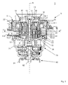
- FIG. 2 shows a cross section according to the level II-II in FIG. 1 ,
- a first upper chamber 7 is provided, which receives the actual grinder 10, and a second lower chamber 8, which receives the Mit supportiverad 25 and serves to convey the ground coffee powder on.
- the housing 6 consists of a first outer wall 6-1, which delimits the first chamber 7, a second wall 6-2, which delimits the second chamber 8, an outlet channel 6-3 and an outlet opening 6-4, from which the ground Coffee powder is discharged from the grinder 1.
- the rotatable conveying element (worm) 12 serves to convey the ground material or the coffee beans along the axis of rotation R into the inlet gap 20 between the first grinding element 11 and the second grinding element 15. With the screw 13, the first grinding element 11, the conveying element 12 and the Mit supportiverad 25 are attached to a drive element 72 of the transmission 70.
- the carrier 16 has snap elements 16-1 for holding the second grinding element 15.
- the fastening ring 17 is fixed to the carrier 16 in order to lock the snap elements 16, so that the second grinding element 15 is held firmly on the carrier 16.
- the annular coupling element 18 consists of an elastic material (eg plastic) and is placed on the support 16 to a top-mounted storage container for the material to be ground (not shown) to couple on the grinder 1.
- the sealing ring 21 is formed as a plastic ring and clamped between the second grinding element 15 and the housing 6, to prevent ground coffee powder can escape upwards.
- the adjusting ring 22 is rotatably mounted about the axis of rotation R on the housing 6, that is, mechanically coupled to the carrier 16, so that the adjusting ring 22 moves the carrier 16 with the second grinding element 15 in the direction of the axis of rotation R up or down, whereby the freeness of Coffees is set.
- the Mit supportiverad 25 serves for transporting the ground coffee powder and is rotatably mounted about the rotation axis R and coupled via the coupling 40 to the first grinding element 11.
- a flat gasket 35 (usually made of felt) seals the bottom of Mit psychologys 25 against the housing 6 and thus prevents escape of the ground coffee powder down.
- the transmission 70 consists of a gear housing 71, a drive element 72, which serves for driving the first grinding element 11 and the driving wings 26, and a rolling bearing 73 with balls 73 ', which guides the drive element 72 on the gear housing 71. From the drive motor 80, the motor housing 81 and a drive shaft 82 of the motor 82 can be partially seen.
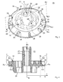
- FIGS. 3 and 4 show the Mit supportiverad 25 with nine uniformly distributed over the circumference, essentially cuboid Mit Anlagenhoffln 26th
- FIG. 4 shows a cross section along the plane E2 in the direction of the arrows IV.
- These driver wings 26 serve to convey the ground coffee powder with a rotation of the Mit supportiverades 25 about the rotation axis R.
- Each driver wing 26 takes on a rotation of the Mit supportiverades 25 with a certain amount of coffee powder and pushes these in the direction of rotation in front of him.
- a sleeve 27 with a central bore 27 ' is provided on the Mitauerrad 25 to the Mit Converserad 25 on a complementary to the sleeve 27 formed portion of the drive element 72 to set up.
- the sleeve 27 also serves to pass the fastening screw 13 in order to fasten the driving wheel 25 to the drive element 72.
- the Mit supportiverad 25 has a transport region T, which is tapered to the refining elements 11 and 15 formed with a concave profile, so that an inner high edge Ri and an outer lower edge Ra is formed.
- the inner edge Ri has a smaller radius ri to the rotation axis R, and the outer edge Ra has a larger radius ra.
- the concave profile of the Mit supportiverades 25 is described by a curve with the formula h (r), the height of the transport region T (with respect to a plane perpendicular to the rotation axis R) in dependence on the distance r from the rotation axis R in the region between the inner edge Ri and the outer edge Ra describes.
- a gap 30 is provided in the Mitauerrad 25, which with a formed on the grinder 10 exit gap 20 'for coffee powder (see FIG. 6 ) flees.
- This gap 30 prevents the ground coffee powder (which passes through the discharge gap 20 'onto the transport region T of the driver wheel 25) from falling onto the top side of the driver blade 26, so that clogging of the second chamber 8 with coffee powder is prevented.
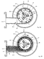
- FIGS. 5A and 5B show a cross section along the line VV in the direction of the arrows V of FIG. 2 ,
- the Mitauerrad 25 is shown without coffee powder, in FIG. 5B with coffee powder P.
- the arrow 25 shows the direction of rotation of the Mit supportiverades 25.
- An arrow ti in Fig. 5B describes schematically a transport path for coffee powder in the second chamber 8 on the transport region T of Mit supportiverads 25 after discharge of the coffee powder from grinder 10 (from the exit slit 20 'according to Fig. 6 ), starting near the inner edge Ri.
- 5B schematically indicates that a displacement of the coffee powder between two driving wings 26 takes place to the outside, due to the concave shape of the profile h (r) and by the centrifugal forces, which arise due to the rotation of the Mit supportiverades 25. This ensures that the ground coffee powder is conveyed after a single revolution of the Mit psychologyrades 25 in the outlet channel 6-3 to the outlet opening 6-4.
- the cross section of the outlet channel 6-4 corresponds approximately to the distance between two driver wings.
- FIG. 6 shows an enlargement of the dashed section A in FIG. 2 .
- the arrow t0 characterizes the direction of the freshly ground coffee powder in the entrance slit 20 between the first and second grinding elements 11 and 15.
- the arrow tr shows the direction of movement of the ground coffee powder emerging from the exit slit 20 'from the high inner edge Ri to the deep outer edge Ra.
- the two arrows t0 and tr concern only the radial components of the movement.
- the arrow tr is curved in accordance with the concave shape of the profile h (r).
- the radial extent (or width) ⁇ r of the concave profile h (r) is determined by the difference between the radius ra of the outer edge Ra and the radius ri of the inner edge Ri.
- Ti indicates the tangent to the curve h (r) at the inner edge Ri in the radial direction. It has an angle ⁇ 1 with the vertical (parallel to the axis of rotation R).
- Ta the tangent to the curve h (r) at the outer edge Ra in the radial direction is designated, which has an angle ⁇ 2 with the horizontal (perpendicular to the axis of rotation R).
- the angle of incidence ⁇ of the ground coffee powder at the exit slit 20 ' is determined by the cone angle of the first grinding element 11 and is between 0 and 45 °, preferably at 5 °.
- the angle ⁇ 1 is between 0 and ⁇ . Further, because of the concave shape of the curve h (r), ⁇ 1 ⁇ arctan ( ⁇ r / ⁇ h) holds for the angle.
- the angle ⁇ 2 is between 0 and arctan ( ⁇ h / ⁇ r).
- the angle ⁇ 2 may be matched to the direction of the exit channel 6-3, i.
- the tangent Ta may be aligned parallel to a longitudinal axis of the exit channel 6-3.
- the exit channel 6-3 is aligned horizontally. The latter has the advantage that a particularly low height of the grinder 1 can be achieved, but the disadvantage that remains after grinding coffee powder in the outlet channel 6-3.
- the curve h (r) is circular with a radius which corresponds to the width ⁇ r of the transport region T.
- the curve h (r) may also be hyperbolic or parabolic, or otherwise concave curved.
- each carrier vane 26 extends radially such that a gap or gap 30 is formed between the driver vane 26 and the inner rim of the transport region Ri.
- This gap 30 should be as small as possible in the radial direction, but at least so wide that coffee powder delivered by the grinder can not fall onto the upper side of the driver wing 26.
- This blockages are prevented by coffee powder in the chamber 8 and the outlet channel 6-3 and ensures that always fresh Ground coffee powder can be transported over the transport area T to the outlet channel 6-3.
- the coffee powder is due to the concave shape of the curve h (r) bundled on the transport section T, compressed and transported as a compact strand directly into the outlet channel 6-3.
- a stream of compressed coffee powder is continuously conveyed from the exit port 6-4 and provided for further use, e.g. in a brewing unit of an automatic coffee machine (not shown).
Abstract
Description
- Die Erfindung bezieht sich auf ein Mahlwerk, welches zum Mahlen von Kaffeebohnen dient.
- Ein solches Mahlwerk ist üblicherweise in Kombination mit einer automatischen Kaffeemaschine vorgesehen, kann jedoch auch allein verwendbar sein.
- Ein Mahlwerk nach dem bekannten Stand der Technik umfasst gewöhnlich:
- eine Mahleinrichtung, welche zum Mahlen von Kaffeebohnen dient und zu diesem Zweck ein erstes Mahlelement und ein zweites Mahlelement aufweist, wobei das erste Mahlelement relativ zum zweiten Mahlelement derart um eine Drehachse drehbar ist, dass Kaffeebohnen zwischen die beiden Mahlelemente gebracht und zu einem Kaffeepulver gemahlen werden;
- ein drehbar gelagertes Mitnehmerrad, welches unterhalb der Mahleinrichtung drehbar gelagert ist und dazu dient, das von der Mahleinrichtung gemahlene Kaffeepulver weiter zu transportieren;
- einen Austrittskanal, über welchen das gemahlene Kaffeepulver das Mahlwerk verlassen kann, wobei das Pulver mittels des Mitnehmerrades zum Austrittskanal geleitet wird.
- Es gibt verschiedene Typen von Mahleinrichtungen, welche sich hinsichtlich der Form und Anordnung der Mahlelemente unterscheiden, z.B. Kegelmahlwerke, Scheibenmahlwerke, usw. Bekannt sind verschiedene Formen von Mitnehmerrädern. Ein Mitnehmerrad kann an der Oberseite einen sich um die Drehachse des Mitnehmerrades erstreckenden Bereich (im Folgenden "Transportbereich") aufweisen, auf welchen das von der Mahleinrichtung gemahlene Kaffeepulver fallen kann. Damit das von der Mahleinrichtung gemahlene Kaffeepulver auf den Transportbereich des Mitnehmerrades fallen kann, muss das Mitnehmerrad entsprechend relativ zur Mahleinrichtung angeordnet sein.
- Beispielsweise sind Mahlwerke mit einem Mitnehmerrad bekannt, welche konisch ausgebildet ist (siehe
EP-A-1964498 ,Fig. 1 ). InDE-A-4418139 ist ein Mitnehmerrad (auch "Austragsteller" genannt) gezeigt, das an seinem äusseren Rand mit sogenannten nach oben gerichteten Windflügeln versehen ist (sieheFiguren 3 und 4 ). Der Transportbereich dieses Mitnehmerrades ist ganz geringfügig kegelförmig ausgebildet, d.h. flach radial nach aussen linear abfallend. Durch die Drehung des Mitnehmerrades wird auf dem Transportbereich befindliches Kaffeepulver einerseits um die Drehachse des Mitnehmerrades mitbewegt und andererseits durch eine Zentrifugalkraft radial nach aussen bewegt. Da der Transportbereich geringfügig linear abfallend ist, wird die radial nach aussen gerichtete Bewegung zusätzlich unterstützt. - Bekannte Mitnehmerräder können mehrere Mitnehmerflügel aufweisen, welche auf der Oberseite des Mitnehmerrades im Transportbereich angeordnet sind und sich radial zur Drehachse erstrecken. Diese Mitnehmerflügel fördern gemahlenes Kaffeepulver bei einer Rotation des Mitnehmerrades in Drehrichtung vor sich her, d.h. längs eines Pfades um die Drehachse herum.
- Aus
DE-A-441813 sind Mitnehmerflügel ("Windflügel 21" gemässFig. 3 ) bekannt, welche am äusseren Rand des Mitnehmerrades (9) angeordnet sind und sich über eine relativ kurze Distanz (verglichen mit der Breite des Transportbereichs) des Mitnehmerrades erstrecken. Nachteilig ist, dass das Kaffeepulver mittels dieser Mitnehmerflügel nicht sehr effizient um die Drehachse befördert wird, sondern eher verwirbelt. Auf das Mitnehmerrad fallendes Pulver bleibt während mehrerer Umdrehungen des Mitnehmerrades im Transportbereich, bevor es den Austrittskanal erreicht, und somit ergibt sich eine geringe Förderleistung. - In
EP-A-1964498 erstrecken sich die Mitnehmerflügel ("ribs 261" gemässFig. 1 und Abschnitt [0013]) radial zur Drehachse des Mitnehmerrades und deren Höhe nimmt in Richtung auf die Drehachse zu null hin ab. Dadurch ergibt sich der Nachteil, dass das gemahlene Pulver auf die Oberseite des Mitnehmerflügels rutschen kann, was zu Verstopfungen führt, sodass eine Rotation des Mitnehmerrades gehemmt wird bzw. das Mitnehmerrad blockiert wird. Abgestandenes Kaffeepulver kann sich auf den Mitnehmerflügeln sammeln und mit frisch gemahlenem Pulver mischen, was den Geschmack des gebrühten Kaffees beeinträchtigt. - Der vorliegenden Erfindung liegt die Aufgabe zugrunde, die genannten Nachteile zu vermeiden, und ein Mahlwerk anzugeben, bei welchem das gemahlene Kaffeepulver schnell und vollständig zum Austrittskanal befördert wird.
- Diese Aufgabe wird gelöst durch ein Mahlwerk mit den Merkmalen des Patentanspruchs 1.
- Das erfindungsgemässe Mahlwerk, welches zum Mahlen von Kaffeebohnen dient, ist mit einem ersten Mahlelement und einem zweiten Mahlelement versehen, wobei die beiden Mahlelemente relativ zueinander derart drehbar sind, dass Kaffeebohnen durch die Mahlelemente zu einem Kaffeepulver vermahlt werden. Ferner ist ein mit dem ersten Mahlelement drehbares Mitnehmerrad vorgesehen, welches dazu dient, auf seinem Randbereich das gemahlene Kaffeepulver über einen Austrittskanal aus dem Mahlwerk hinaus zu führen. Der Randbereich des Mitnehmerrades ist zu den Mahlelementen hin verjüngt mit einem konkaven Profil derart ausgebildet, dass ein innerer hoher Rand und ein äusserer tiefer Rand gebildet sind, und das Mitnehmerrad mehrere im Randbereich über den Umfang verteilte Mitnehmerflügel aufweist.
- Das erfindungsgemässe Mahlwerk hat den grossen Vorteil, dass es sehr kompakt ist und eine verbesserte Förderleistung gegenüber herkömmlichen Mahlwerken aufweist. Die spezielle Ausbildung des Mitnehmerrades mit den Mitnehmerflügeln bewirkt, dass gemahlenes Kaffeepulver sehr schnell aus der Mahlvorrichtung in den Austrittskanal befördert wird. Weiterhin ist die Restmenge Kaffeepulver - d.h. das nach Beenden eines Mahlvorgangs auf dem Mitnehmerrad und im Austrittskanal verbleibende gemahlene Kaffeepulver - wesentlich geringer.
- Weitere Vorteile ergeben sich aus der untenstehenden Beschreibung und den Unteransprüchen.
- Weitere Einzelheiten der Erfindung und insbesondere beispielhafte Ausführungsformen der erfindungsgemässen Vorrichtung werden im Folgenden anhand der beigefügten Zeichnungen erläutert. Es zeigen:
- Fig. 1
- eine Explosionsdarstellung eines Mahlwerks mit einer Mahleinrichtung und einem Mitnehmerrad;
- Fig. 2
- das Mahlwerk gemäss
Fig. 1 in einem Querschnitt durch die Ebene E1 gemässFig. 1 ; - Fig. 3
- eine perspektivische Ansicht des Mitnehmerrades gemäss
Fig. 1 ; - Fig. 4
- das Mitnehmerrad gemäss
Fig. 3 in einem Querschnitt durch die Ebene E2 gemässFig. 3 ; - Fig. 5A
- das Mahlwerk gemäss
Fig. 2 in einem Querschnitt entlang des Schnitts V-V in einem leeren Zustand (ohne gemahlenes Kaffeepulver); - Fig. 5B
- das Mahlwerk gemäss
Fig. 2 in einem Querschnitt entlang des Schnitts V-V in einem gefüllten Zustand (mit gemahlenem Kaffeepulver); und - Fig. 6
- einen vergrösserten Ausschnitt der Darstellung des Mahlwerks entsprechend dem Rechteck A in
Fig. 2 . - Für dieselben Elemente in den Figuren sind jeweils dieselben Bezugszeichen verwendet, wenn nichts anderes erwähnt ist.
- In
Figur 1 ist (perspektivisch und in Explosionsdarstellung) ein Mahlwerk 1 zum Mahlen von Kaffeebohnen gezeigt, welches aus einer Mahlvorrichtung 5 mit einem Getriebe 70 und einem Antriebsmotor 80 besteht. Die Mahlvorrichtung 5 ist aufgeteilt in eine Mahleinrichtung 10, eine Rutschkupplung 40 und ein Mitnehmerrad 25, wobei diese Teile von einem Gehäuse 6 umgeben sind. Das Mahlwerk 1 ist im vorliegenden Beispiel als "Kegelmahlwerk" ausgebildet. Entsprechend weist die Mahleinrichtung 10 ein erstes Mahlelement 11 (im vorliegenden Beispiel ein Mahlkegel mit schraubenförmigen Messern) und ein zweites Mahlelement 15 (im vorliegenden Beispiel ein Mahlring) auf. Das erste Mahlelement 11 ist drehbar relativ zum zweiten Mahlelement 15 angeordnet. In der Reihenfolge vom Mahlelement 11 nach oben sind ein drehbares Förderelement 12 (im vorliegenden Beispiel ausgebildet als Schnecke), eine Befestigungsschraube 13, ein Dichtungsring 21, ein Befestigungsring 17 für das zweite Mahlelement 15, ein Träger 16, ein Einstellring 22 und ein Kopplungselement 18 vorgesehen. Unterhalb des ersten Mahlelementes 11 ist eine Rutschkupplung 40 angebracht, welche drei Kugeln 40-1, drei Druckfedern 40-2 und drei Hülsen 40-3 aufweist. Bei einem Verklemmen des ersten Mahlelementes 11 Mitnehmerrades 25 sorgt die Rutschkupplung in bekannter Weise dafür, dass das Mitnehmerrad 25 mit dem Antriebsmotor 80 relativ zum ersten Mahlelement 11 gedreht werden kann, sodass die Mahleinrichtung 10 nicht festläuft und der Antriebsmotor 80 somit nicht überhitzen kann. -
Figur 2 zeigt einen Querschnitt gemäss der Ebene II-II inFigur 1 . Im Gehäuse 6 ist eine erste obere Kammer 7 vorgesehen, welche die eigentliche Mahleinrichtung 10 aufnimmt, und eine zweite untere Kammer 8, welche das Mitnehmerrad 25 aufnimmt und dazu dient, das gemahlene Kaffeepulver weiter zu befördern. Das Gehäuse 6 besteht aus einer ersten äusseren Wand 6-1, welche die erste Kammer 7 begrenzt, einer zweiten Wand 6-2, welche die zweite Kammer 8 begrenzt, ein Austrittskanal 6-3 und eine Austrittsöffnung 6-4, aus welchem das gemahlene Kaffeepulver aus dem Mahlwerk 1 abgegeben wird. Das drehbare Förderelement (Schnecke) 12 dient dazu, das Mahlgut oder die Kaffeebohnen entlang der Drehachse R in den Eintrittsspalt 20 zwischen dem ersten Mahlelement 11 und dem zweiten Mahlelement 15 zu befördern. Mit der Schraube 13 sind das erste Mahlelement 11, das Förderelement 12 und das Mitnehmerrad 25 an einem Antriebselement 72 des Getriebes 70 befestigt. Der Träger 16 weist Schnappelemente 16-1 zum Halten des zweiten Mahlelements 15 auf. - Der Befestigungsring 17 ist am Träger 16 fixiert, um die Schnappelemente 16 zu verriegeln, so dass das zweite Mahlelement 15 fest am Träger 16 gehalten ist. Das ringförmige Kopplungselement 18 besteht aus einem elastischen Material (z.B. Kunststoff) und ist auf dem Träger 16 aufgesetzt, um einen von oben aufsetzbaren Vorratsbehälter für das Mahlgut (nicht dargestellt) auf dem Mahlwerk 1 anzukoppeln. Der Dichtungsring 21 ist als Flachring aus Kunststoff ausgebildet und zwischen dem zweiten Mahlelement 15 und dem Gehäuse 6 eingeklemmt, um zu verhindern, dass gemahlenes Kaffeepulver nach oben entweichen kann. Der Einstellring 22 ist drehbar um die Drehachse R am Gehäuse 6 gelagert, d.h. mechanisch gekoppelt am Träger 16, so dass der Einstellring 22 den Träger 16 mit dem zweiten Mahlelement 15 in Richtung der Drehachse R nach oben oder nach unten verschiebt, womit der Mahlgrad des Kaffees eingestellt wird. Das Mitnehmerrad 25 dient zum Transportieren des gemahlenen Kaffeepulvers und ist um die Drehachse R drehbar gelagert und über die Kupplung 40 an das erste Mahlelement 11 gekoppelt. Eine Flachdichtung 35 (in der Regel aus Filz) dichtet die Unterseite des Mitnehmerrades 25 gegen das Gehäuse 6 ab und verhindert somit ein Entweichen des gemahlenen Kaffeepulvers nach unten. Das Getriebe 70 besteht aus einem Getriebe-Gehäuse 71, einem Antriebselement 72, welches zum Antreiben des ersten Mahlelements 11 und der Mitnehmerflügel 26 dient, und einem Wälzlager 73 mit Kugeln 73', welches das Antriebselement 72 am Getriebe-Gehäuse 71 führt. Vom Antriebsmotor 80 sind teilweise das Motorgehäuse 81 und eine Antriebswelle 82 des Motors 82 zu sehen.
- Die
Figuren 3 und 4 zeigen das Mitnehmerrad 25 mit neun gleichmässig über den Umfang verteilten, im Wesentlichen quaderförmigen Mitnehmerflügeln 26.Figur 4 zeigt ein Querschnitt längs der Ebene E2 in Richtung der Pfeile IV. Diese Mitnehmerflügel 26 dienen zum Befördern des gemahlenen Kaffeepulvers bei einer Rotation des Mitnehmerrades 25 um die Drehachse R. Jeder Mitnehmerflügel 26 nimmt bei einer Rotation des Mitnehmerrades 25 eine bestimmte Menge Kaffeepulver mit und schiebt diese in der Drehrichtung vor sich her. Eine Hülse 27 mit einer zentralen Bohrung 27' ist an dem Mitnehmerrad 25 vorgesehen, um das Mitnehmerrad 25 auf einen komplementär zur Hülse 27 ausgebildeten Abschnitt des Antriebselements 72 aufzusetzen. Die Hülse 27 dient ferner zur Durchführung der Befestigungsschraube 13, um das Mitnehmerrad 25 am Antriebselement 72 zu befestigen. Um die Hülse 27 sind drei Kreiszylinder 28 mit jeweils einer Bohrung 28' angeordnet, welche zur Aufnahme der Komponenten der Rutschkupplung 40 dienen. - Das Mitnehmerrad 25 weist einen Transportbereich T auf, der zu den Mahlelementen 11 und 15 hin verjüngt mit einem konkaven Profil ausgebildet ist, so dass ein innerer hoher Rand Ri und ein äusserer tiefer Rand Ra gebildet ist. Der innere Rand Ri weist einen kleineren Radius ri zur Drehachse R auf, und der äussere Rand Ra weist einen grösseren Radius ra auf. Das konkave Profil des Mitnehmerrades 25 wird durch eine Kurve mit der Formel h(r) beschrieben, welche die Höhe des Transportbereichs T (bezüglich einer zur Drehachse R senkrechten Ebene) in Abhängigkeit vom Abstands r von der Drehachse R im Bereich zwischen dem inneren Rand Ri und dem äusseren Rand Ra beschreibt. Zwischen dem inneren Rand Ri und dem Mitnehmerflügel 26 ist ein Spalt 30 in dem Mitnehmerrad 25 vorgesehen, welche mit einem an der Mahleinrichtung 10 ausgebildeten Austrittsspalt 20' für Kaffeepulver (siehe
Figur 6 ) fluchtet. Dieser Spalt 30 verhindert, dass das von der Mahleinrichtung 10 gemahlene Kaffeepulver (welches über den Austrittsspalt 20' auf den Transportbereich T des Mitnehmerrads 25 gelangt) auf die Oberseite des Mitnehmerflügels 26 fällt, sodass eine Verstopfung der zweiten Kammer 8 mit Kaffeepulver verhindert wird. - Die
Figuren 5A und 5B zeigen einen Querschnitt längs der Linie V-V in Richtung der Pfeile V derFigur 2 . InFigur 5A ist das Mitnehmerrad 25 ohne Kaffeepulver dargestellt, inFigur 5B mit Kaffeepulver P. Der Pfeil 25' zeigt die Drehrichtung des Mitnehmerrades 25. Ein Pfeil ti inFig. 5B beschreibt schematisch einen Transportpfad für Kaffeepulver in der zweiten Kammer 8 auf dem Transportbereich T des Mitnehmerrads 25 nach dem Austritt des Kaffeepulvers aus Mahleinrichtung 10 (aus dem Austrittspalt 20' gemässFig. 6 ), beginnend in der Nähe des inneren Randes Ri. Wie der Pfeil ti inFig. 5B schematisch andeutet, findet eine Verschiebung des Kaffeepulvers zwischen zwei Mitnehmerflügeln 26 nach aussen statt, bedingt durch die konkave Form des Profils h(r) und durch die Zentrifugalkräfte, welche durch die Rotation des Mitnehmerrades 25 entstehen. Damit wird gewährleistet, dass das gemahlene Kaffeepulver nach einer einzigen Umdrehung des Mitnehmerrades 25 in den Austrittskanal 6-3 zur Austrittsöffnung 6-4 befördert wird. Der Querschnitt des Austrittskanals 6-4 entspricht dabei etwa der Abstand zwischen zwei Mitnehmerflügeln. -
Figur 6 zeigt eine Vergrösserung des gestrichelten Ausschnitts A inFigur 2 . Mit dem Pfeil t0 wird die Richtung des frisch gemahlenen Kaffeepulvers im Eintrittsspalt 20 zwischen dem ersten und zweiten Mahlelement 11 und 15 charakterisiert. Mit dem Pfeil tr wird die Richtung der Bewegung des aus dem Austrittsspalt 20' austretenden gemahlenen Kaffeepulvers vom hohen inneren Rand Ri zum tiefen äusseren Rand Ra gezeigt. Die beiden Pfeile t0 und tr betreffen nur die radialen Komponenten der Bewegung. Wie ersichtlich, ist der Pfeil tr entsprechend der konkaven Form des Profils h(r) gekrümmt. Die radiale Erstreckung (bzw. Breite) Δr des konkaven Profils h(r) ist durch die Differenz zwischen dem Radius ra des äusseren Randes Ra und dem Radius ri des inneren Randes Ri bestimmt. Mit Ti ist die Tangente an der Kurve h(r) am inneren Rand Ri in radialer Richtung angegeben. Sie weist einen Winkel β1 mit der Senkrechten (parallel zur Drehachse R) auf. Mit Ta ist die Tangente an der Kurve h(r) am äusseren Rand Ra in radialer Richtung bezeichnet, welche einen Winkel β2 mit der Horizontalen (senkrecht zur Drehachse R) aufweist. Der Einfallswinkel α des gemahlenen Kaffeepulvers beim Austrittsspalt 20' wird durch den Kegelwinkel des ersten Mahlelements 11 bestimmt und liegt zwischen 0 und 45°, vorzugsweise bei 5°. Der Winkel β1 liegt zwischen 0 und α. Wegen der konkaven Form der Kurve h(r) gilt ferner für den Winkel β1 ≤ arctan (Δr/Δh). Der Winkel β2 liegt zwischen 0 und arctan (Δh/Δr). - Ansonsten kann der Winkel β2 an die Richtung des Austrittskanals 6-3 angepasst sein, d.h. die Tangente Ta kann beispielsweise parallel zu einer Längsachse des Austrittskanals 6-3 ausgerichtet sein. Im vorliegenden Beispiel ist der Austrittskanal 6-3 horizontal ausgerichtet. Letzteres hat den Vorteil, dass eine besonders geringe Bauhöhe des Mahlwerks 1 erreicht werden kann, aber den Nachteil, dass nach dem Mahlen Kaffeepulver im Austrittskanal 6-3 verbleibt.
- Das konkave Profil h(r) als konkav gekrümmte Kurve hat folgende wichtige Auswirkungen:
- a) Der Transportbereich T hat am inneren Rand Ri des Transportbereichs eine grössere Steigung, verglichen mit einem linearen Höhenprofil bei gleichen Erstreckungen Δh und Δr. Die grössere Steigung führt zu einem effizienten Transport von Kaffeepulver in radialer Richtung nach aussen, unter der Voraussetzung, dass das Kaffeepulver in der Nähe des inneren Randes Ri auf den Transportbereich T fällt. Dadurch erreicht man eine Verbesserung der Förderleistung.
- b) In der zweiten Kammer 8, in welcher das Mitnehmerrad 25 angeordnet ist, steht wegen der Ausbildung des Höhenprofils h(r) als konkav gekrümmte Kurve ein grösseres Volumen zur Aufnahme von Pulver zur Verfügung, verglichen mit einem linearen Höhenprofil bei gleichen Erstreckungen Δh und Δr. Der Transportbereich T kann folglich eine grössere Menge Pulver aufnehmen, was zu einer Steigerung der Transportkapazität führt.
- Die Parameter Δh und Δr und die Krümmung der Kurve h(r) dienen einer Optimierung:
- a) und b) bewirken eine Verbesserung der Förderleistung (d.h. die Menge Kaffeepulver, welche pro Umdrehung des Mitnehmerrades den Austrittskanal verlässt),
- Δh, Δr und die Krümmung der Kurve h (r) bestimmen die Grösse der Restmenge, welche möglichst klein sein soll,
- Δh, Δr und die Krümmung der Kurve h (r) werden so gewählt, dass im Wesentlichen Kaffeepulver, welches bei einer Umdrehung des ersten Mahlelements 11 erzeugt wird und auf das Mitnehmerrad 25 fällt, im Wesentlichen spätestens nach einer einzigen Umdrehung des Mitnehmerrades 25 den Austrittskanal 6-3 erreicht.
- Im vorliegenden Fall ist die Kurve h(r) kreisförmig mit einem Radius, welcher der Breite Δr des Transportbereichs T entspricht. Die Kurve h(r) kann jedoch auch hyperbolisch oder parabolisch geformt oder auf eine andere Weise konkave gekrümmt sein.
- Bezüglich der Mitnehmer-Flügel 26 ist relevant, dass sich jeder Mitnehmerflügel 26 radial derart erstreckt, dass ein Spalt oder eine Lücke 30 zwischen dem Mitnehmerflügel 26 und dem inneren Rand des Ri des Transportbereichs ausgebildet ist. Diese Lücke 30 soll in radialer Richtung möglichst klein sein, aber mindestens so breit, dass von der Mahleinrichtung abgegebenes Kaffeepulver nicht auf die Oberseite der Mitnehmerflügel 26 fallen kann. Damit werden Verstopfungen durch Kaffeepulver in der Kammer 8 und im Austrittskanal 6-3 verhindert und wird sichergestellt, dass stets frisch gemahlenes Kaffeepulver über den Transportbereich T zum Austrittskanal 6-3 transportiert werden kann.
- Das Kaffeepulver wird aufgrund der konkaven Form der Kurve h(r) auf dem Transportbereicht T gebündelt, komprimiert und als kompakter Strang direkt in den Austrittskanal 6-3 transportiert. Im Betrieb des Mahlwerks 1 wird ein derartiger Strang aus komprimiertem Kaffeepulver kontinuierlich aus der Austrittsöffnung 6-4 gefördert und zur weiteren Verwendung bereitgestellt, z.B. in einer Brüheinheit einer automatischen Kaffeemaschine (nicht dargestellt).
- Mit dem Mahlwerk 1 fällt (bei entsprechender Wahl von Δh, Δr und der Krümmung der Kurve h(r)) eine geringe Restmenge von etwa 1 bis 1,5 Gramm in der Kammer 8 des Mitnehmerrades 25 an, so dass stets ein hoher Anteil an frisch gemahlenem Kaffeepulver vorhanden ist, selbst wenn vom Mahlwerk 1 Kaffeepulver für eine Kaffeespezialität bereitgestellt werden soll, welche aus einer geringen Kaffeepulver gebrüht wird, beispielsweise aus etwa 10-12 Gramm Kaffeepulver im Falle eines Espresso.
Claims (10)
- Mahlwerk (1), welches zum Mahlen von Kaffeebohnen dient, mit einem ersten Mahlelement (11) und einem zweiten Mahlelement (15), wobei die beiden Mahlelemente (11, 15) relativ zueinander derart drehbar sind, dass Kaffeebohnen durch die Mahlelemente zu einem Kaffeepulver vermahlt werden, und mit einer mit dem ersten Mahlelement drehbaren Mitnehmerrad (25), welche dazu dient, auf seinem Randbereich das gemahlene Kaffeepulver über einen Austrittskanal (6-3) aus dem Mahlwerk hinaus zu führen,
dadurch gekennzeichnet, dass
der Randbereich des Mitnehmerrades (25) zu den Mahlelementen (11, 15) hin verjüngt mit einem konkaven Profil (h(r)) ausgebildet ist, derart, dass ein innerer hoher Rand (Ri) und ein äusserer tiefer Rand (Ra) gebildet sind, und das Mitnehmerrad (25) mehrere im Randbereich über den Umfang verteilte Mitnehmerflügel (26) aufweist. - Mahlwerk nach Anspruch 1, dadurch gekennzeichnet, dass die Mitnehmerflügel (26) radial auf dem Mitnehmerrad (25) ausgerichtet sind.
- Mahlwerk nach Anspruch 1 oder 2, dadurch gekennzeichnet, dass die Mitnehmerflügel (26) in einem regelmässigen Abstand zueinander über dem Umfang verteilt sind.
- Mahlwerk nach einem der Ansprüche 1 bis 3, dadurch gekennzeichnet, dass zwischen dem Mitnehmerflügel (26) und dem inneren hohen Rand (Ri) ein Spalt (30) vorgesehen ist, derart, dass ein zwischen dem ersten Mahlelement (11) und dem zweiten Mahlelement (15) ausgebildeter Austrittsspalt (20') für das gemahlene Kaffeepulver in den Spalt (30) mündet, wobei der Spalt (30) dazu dient, das gemahlene Kaffeepulver direkt zu übernehmen.
- Mahlwerk nach einem der Ansprüche 1 bis 4, dadurch gekennzeichnet, dass die Mitnehmerflügel (26) im Wesentlichen quaderförmig ausgebildet sind.
- Mahlwerk nach einem der Ansprüche 1 bis 5, dadurch gekennzeichnet, dass die Höhe der Mitnehmerflügel (26) der Höhe des inneren Rands (Ri) entspricht.
- Mahlwerk nach einem der Ansprüche 1 bis 6, dadurch gekennzeichnet, dass das konkave Profil (h(r)) im Querschnitt kreisförmig ist.
- Mahlwerk nach Anspruch 7, dadurch gekennzeichnet, dass der Kreisradius des konkaven Profils (h(r)) dem Abstand zwischen dem inneren Rand (Ri) und dem äusseren Rand (Ra) entspricht.
- Mahlwerk nach einem der Ansprüche 1 bis 6, dadurch gekennzeichnet, dass das konkave Profil (h(r)) im Querschnitt hyperbolisch oder parabolisch ist.
- Mahlwerk nach einem der Ansprüche 1 bis 9, dadurch gekennzeichnet, dass der Austrittskanal (6-3) derart geformt ist, dass dessen Höhe im Wesentlichen der Höhe des Mitnehmerrad (25) und dessen Breite im Wesentlichen dem Abstand zwischen zwei Mitnehmerflügeln (26) entspricht.
Priority Applications (2)
| Application Number | Priority Date | Filing Date | Title |
|---|---|---|---|
| PL14405005T PL2764808T3 (pl) | 2013-02-12 | 2014-02-06 | Młynek |
| EP14405005.1A EP2764808B1 (de) | 2013-02-12 | 2014-02-06 | Mahlwerk |
Applications Claiming Priority (2)
| Application Number | Priority Date | Filing Date | Title |
|---|---|---|---|
| EP13405031.9A EP2764807A1 (de) | 2013-02-12 | 2013-02-12 | Mahlwerk |
| EP14405005.1A EP2764808B1 (de) | 2013-02-12 | 2014-02-06 | Mahlwerk |
Publications (2)
| Publication Number | Publication Date |
|---|---|
| EP2764808A1 true EP2764808A1 (de) | 2014-08-13 |
| EP2764808B1 EP2764808B1 (de) | 2015-09-16 |
Family
ID=47748556
Family Applications (2)
| Application Number | Title | Priority Date | Filing Date |
|---|---|---|---|
| EP13405031.9A Withdrawn EP2764807A1 (de) | 2013-02-12 | 2013-02-12 | Mahlwerk |
| EP14405005.1A Not-in-force EP2764808B1 (de) | 2013-02-12 | 2014-02-06 | Mahlwerk |
Family Applications Before (1)
| Application Number | Title | Priority Date | Filing Date |
|---|---|---|---|
| EP13405031.9A Withdrawn EP2764807A1 (de) | 2013-02-12 | 2013-02-12 | Mahlwerk |
Country Status (12)
| Country | Link |
|---|---|
| US (1) | US9980610B2 (de) |
| EP (2) | EP2764807A1 (de) |
| CN (1) | CN103976665B (de) |
| AU (1) | AU2014200382B2 (de) |
| CA (1) | CA2839899A1 (de) |
| ES (1) | ES2554708T3 (de) |
| HK (1) | HK1198889A1 (de) |
| MX (1) | MX338161B (de) |
| PL (1) | PL2764808T3 (de) |
| PT (1) | PT2764808E (de) |
| RU (1) | RU2636573C2 (de) |
| ZA (1) | ZA201400320B (de) |
Cited By (4)
| Publication number | Priority date | Publication date | Assignee | Title |
|---|---|---|---|---|
| EP3114975A1 (de) * | 2015-07-10 | 2017-01-11 | Jura Elektroapparate Ag | Mahlwerk für kaffeemaschinen |
| DE102016103806A1 (de) | 2016-03-03 | 2017-09-07 | Eugster / Frismag Ag | Kaffeemühle sowie Kaffeevollautomat mit Kaffeemühle |
| EP3581078A1 (de) | 2018-06-14 | 2019-12-18 | Jura Elektroapparate AG | Mahlvorrichtung zum mahlen von kaffeebohnen |
| RU2787772C2 (ru) * | 2018-08-21 | 2023-01-12 | Юра Электроаппарате АГ | Помольное устройство для размалывания помольного материала |
Families Citing this family (18)
| Publication number | Priority date | Publication date | Assignee | Title |
|---|---|---|---|---|
| USD899194S1 (en) * | 2007-11-29 | 2020-10-20 | Automatic Bar Controls, Inc. | Dispensing apparatus |
| ITVE20130032A1 (it) * | 2013-06-26 | 2014-12-27 | Mazzer Luigi S R L | Macinadosatore per caffe'. |
| CA2949443C (en) * | 2014-05-26 | 2022-08-23 | Drogheria E Alimentari S.P.A. | A grinding device for grindable products |
| EP3250096B1 (de) * | 2015-01-28 | 2020-07-29 | Sanremo Coffee Machines SRL | Vorrichtung zum mahlen von kaffeebohnen |
| KR101674375B1 (ko) * | 2015-07-23 | 2016-11-09 | 조현민 | 커피 분쇄 장치에 사용되는 분쇄 조절판 |
| CN105167615B (zh) * | 2015-09-15 | 2017-11-28 | 广东新宝电器股份有限公司 | 一种咖啡机磨豆系统 |
| CN106913217A (zh) * | 2015-12-24 | 2017-07-04 | 威斯达电器(中山)制造有限公司 | 磨豆装置及具有该磨豆装置的自动咖啡壶 |
| DE102016100396B4 (de) | 2016-01-12 | 2017-11-16 | Eugster/Frismag Ag | Kaffeebohnen-Mahlwerk für Kaffeezubereitungsvorrichtung sowie Kaffeezubereitungsvorrichtung |
| IT201700118492A1 (it) * | 2017-10-19 | 2019-04-19 | Mazzer Luigi Spa | Macinadosatore per caffe’ con sistema riposizionabile di indicazione della posizione dei mezzi di regolazione della distanza tra le macine |
| WO2019135422A1 (ko) * | 2018-01-03 | 2019-07-11 | 윤임규 | 맷돌형 분쇄기 |
| CN108670060A (zh) * | 2018-05-21 | 2018-10-19 | 蒋其猛 | 利用率高的磨豆机 |
| CN108514344A (zh) * | 2018-05-21 | 2018-09-11 | 蒋其猛 | 全自动磨豆机 |
| IT201800006618A1 (it) * | 2018-06-25 | 2019-12-25 | Apparato per la produzione automatizzata di compresse di prodotti alimentari per l'estrazione a caldo di bevande | |
| EP3613319A1 (de) | 2018-08-21 | 2020-02-26 | Jura Elektroapparate AG | Mahlwerk zum mahlen von mahlgut |
| US11619112B2 (en) | 2018-10-22 | 2023-04-04 | Halliburton Energy Services, Inc. | Rotating cutter apparatus for reducing the size of solid objects in a fluid |
| CN115868823A (zh) * | 2021-08-18 | 2023-03-31 | 苏州咖乐美咖啡机科技有限公司 | 研磨装置 |
| USD988592S1 (en) * | 2021-08-19 | 2023-06-06 | G&E Innovations Inc. | Combined grinder and cone filler |
| IT202100029852A1 (it) | 2021-11-25 | 2022-02-25 | Davide Cappellini | Dispositivo e un procedimento per macinare e dosare caffè. |
Citations (3)
| Publication number | Priority date | Publication date | Assignee | Title |
|---|---|---|---|---|
| DE4418139C1 (de) * | 1994-05-25 | 1995-02-09 | Samaro Eng & Handel | Mahlwerk für Kaffeemühlen |
| EP1964498A1 (de) * | 2007-02-06 | 2008-09-03 | Chung-Jen Pai | Mühle |
| EP2050377A1 (de) * | 2007-10-16 | 2009-04-22 | Eldom Rothrist AG | Mahlwerkzeug |
Family Cites Families (16)
| Publication number | Priority date | Publication date | Assignee | Title |
|---|---|---|---|---|
| DE441813C (de) | 1924-07-22 | 1927-03-14 | Richard Cobden Rogers | Schablonenbaltt fuer Rotationsschablonendrucker |
| US2181000A (en) * | 1936-07-30 | 1939-11-21 | John J Shively | Ice chipping device |
| US3938745A (en) * | 1974-10-10 | 1976-02-17 | Gladwin Floyd R | Bottle crusher |
| DE3130519A1 (de) * | 1981-08-01 | 1983-02-17 | A. Hilmar Dr.-Ing. 7031 Aidlingen Burggrabe | Mahlwerk einer haushalts-getreidemuehle |
| US5697528A (en) * | 1995-06-19 | 1997-12-16 | Conair Corporation | Coffee mill adapted for controlled mixing of coffee beans |
| US7273005B2 (en) * | 2004-06-18 | 2007-09-25 | Saeco Ipr Limited | Coffee grinder assembly for a coffee machine |
| ITFI20060281A1 (it) * | 2006-11-14 | 2008-05-15 | Saeco Ipr Ltd | Organi di macinazione per un dispositivo macina caffe' ed una macchina da caffe' comprendente tale dispositivo. |
| US20080216663A1 (en) * | 2007-03-09 | 2008-09-11 | Steve Williamson | Brewed beverage maker with dispensing assembly |
| US7878437B2 (en) * | 2007-10-22 | 2011-02-01 | Berry Plastics Corporation | Canister with adjustable grinder |
| TW200927046A (en) * | 2007-12-24 | 2009-07-01 | Tzung-Ren Bai | Grinder and the automatic on/off control device |
| NZ616551A (en) * | 2008-09-17 | 2015-09-25 | Koninkl Douwe Egberts Bv | System for preparing coffee beverage |
| ITFI20090256A1 (it) * | 2009-12-11 | 2011-06-12 | Koninkl Philips Electronics Nv | "dispositivo di dosaggio di caffe' macinato e macchina comprendente tale dispositivo" |
| NL2006239C2 (en) * | 2010-02-17 | 2012-08-09 | Sara Lee De Nv | Coffee beverage system, second coffee bean packaging cartridge for use with said system, method for preparing a beverage by means of said system, a method of brewing coffee and a method of supplying coffee beans from said second coffee bean packaging cartridge. |
| DE102010017721A1 (de) * | 2010-07-05 | 2010-12-30 | SEVERIN ELEKTROGERÄTE GmbH | Mahlwerk |
| US8646379B2 (en) * | 2010-11-15 | 2014-02-11 | Conair Corporation | Brewed beverage appliance and method |
| CN202515436U (zh) * | 2011-11-30 | 2012-11-07 | 伟嘉电业有限公司 | 咖啡豆研磨机 |
-
2013
- 2013-02-12 EP EP13405031.9A patent/EP2764807A1/de not_active Withdrawn
-
2014
- 2014-01-15 ZA ZA2014/00320A patent/ZA201400320B/en unknown
- 2014-01-20 CA CA2839899A patent/CA2839899A1/en not_active Abandoned
- 2014-01-23 US US14/162,148 patent/US9980610B2/en active Active
- 2014-01-23 AU AU2014200382A patent/AU2014200382B2/en not_active Ceased
- 2014-02-05 MX MX2014001414A patent/MX338161B/es active IP Right Grant
- 2014-02-06 PL PL14405005T patent/PL2764808T3/pl unknown
- 2014-02-06 ES ES14405005.1T patent/ES2554708T3/es active Active
- 2014-02-06 EP EP14405005.1A patent/EP2764808B1/de not_active Not-in-force
- 2014-02-06 PT PT144050051T patent/PT2764808E/pt unknown
- 2014-02-07 CN CN201410045301.6A patent/CN103976665B/zh not_active Expired - Fee Related
- 2014-02-11 RU RU2014104794A patent/RU2636573C2/ru not_active IP Right Cessation
- 2014-12-12 HK HK14112503.9A patent/HK1198889A1/xx not_active IP Right Cessation
Patent Citations (3)
| Publication number | Priority date | Publication date | Assignee | Title |
|---|---|---|---|---|
| DE4418139C1 (de) * | 1994-05-25 | 1995-02-09 | Samaro Eng & Handel | Mahlwerk für Kaffeemühlen |
| EP1964498A1 (de) * | 2007-02-06 | 2008-09-03 | Chung-Jen Pai | Mühle |
| EP2050377A1 (de) * | 2007-10-16 | 2009-04-22 | Eldom Rothrist AG | Mahlwerkzeug |
Cited By (10)
| Publication number | Priority date | Publication date | Assignee | Title |
|---|---|---|---|---|
| EP3114975A1 (de) * | 2015-07-10 | 2017-01-11 | Jura Elektroapparate Ag | Mahlwerk für kaffeemaschinen |
| RU2699843C1 (ru) * | 2015-07-10 | 2019-09-11 | Юра Электроаппарате АГ | Мельница для кофемашины |
| US10765259B2 (en) | 2015-07-10 | 2020-09-08 | Jura Elektroapparate Ag | Grinder for coffee machine |
| DE102016103806A1 (de) | 2016-03-03 | 2017-09-07 | Eugster / Frismag Ag | Kaffeemühle sowie Kaffeevollautomat mit Kaffeemühle |
| EP3216375A1 (de) | 2016-03-03 | 2017-09-13 | Eugster/Frismag AG | Kaffeemühle sowie kaffeevollautomat mit kaffeemühle |
| DE102016103806B4 (de) | 2016-03-03 | 2019-01-17 | Eugster / Frismag Ag | Kaffeemühle sowie Kaffeevollautomat mit Kaffeemühle |
| EP3581078A1 (de) | 2018-06-14 | 2019-12-18 | Jura Elektroapparate AG | Mahlvorrichtung zum mahlen von kaffeebohnen |
| EP3581079A1 (de) | 2018-06-14 | 2019-12-18 | Jura Elektroapparate AG | Mahlvorrichtung zum mahlen von kaffeebohnen |
| US11389029B2 (en) | 2018-06-14 | 2022-07-19 | Jura Elektroapparate Ag | Grinding device for grinding coffee beans |
| RU2787772C2 (ru) * | 2018-08-21 | 2023-01-12 | Юра Электроаппарате АГ | Помольное устройство для размалывания помольного материала |
Also Published As
| Publication number | Publication date |
|---|---|
| EP2764808B1 (de) | 2015-09-16 |
| US9980610B2 (en) | 2018-05-29 |
| MX2014001414A (es) | 2014-11-05 |
| PT2764808E (pt) | 2015-11-30 |
| RU2636573C2 (ru) | 2017-11-23 |
| RU2014104794A (ru) | 2015-08-20 |
| CA2839899A1 (en) | 2014-08-12 |
| CN103976665A (zh) | 2014-08-13 |
| US20140224910A1 (en) | 2014-08-14 |
| ES2554708T3 (es) | 2015-12-22 |
| MX338161B (es) | 2016-04-05 |
| AU2014200382B2 (en) | 2017-11-30 |
| AU2014200382A1 (en) | 2014-08-28 |
| EP2764807A1 (de) | 2014-08-13 |
| PL2764808T3 (pl) | 2016-01-29 |
| HK1198889A1 (en) | 2015-06-19 |
| CN103976665B (zh) | 2017-12-15 |
| ZA201400320B (en) | 2014-10-29 |
Similar Documents
| Publication | Publication Date | Title |
|---|---|---|
| EP2764808B1 (de) | Mahlwerk | |
| EP2125230B1 (de) | Verfahren zum kontinuierlichen trocken-mahl-betrieb einer turm-reib-mühle und turm-reib-mühle | |
| EP2036613B1 (de) | Rührwerkskugelmühle | |
| EP2858539B1 (de) | Kaffeemaschine | |
| EP1468739A1 (de) | Rührwerkskugelmühle | |
| WO2009024158A1 (de) | Rührwerksmühle | |
| WO2009024159A1 (de) | Rührwerksmühle | |
| EP0638365B1 (de) | Verfahren und Vorrichtung zur Trennung eines feinkörnigen Feststoffes in zwei Kornfraktionen | |
| EP2119345B1 (de) | Futtermischer | |
| DE20308404U1 (de) | Mischer | |
| DE102013108109A1 (de) | Vorrichtung zum Zerkleinern von Raufutter | |
| EP3897319B1 (de) | Mahlwerk mit konvex gekrümmten mahlvorsprüngen | |
| EP2497359A2 (de) | Mischschnecke für Futtermischwagen | |
| DE3209610A1 (de) | Schleuderrad fuer schleuderstrahlmaschinen | |
| EP2904897B1 (de) | Mischvorrichtung | |
| DE202010008642U1 (de) | Kaffeebohnenmühle | |
| AT506464B1 (de) | Vorrichtung zum befüllen eines lagerraumes mit stückeligem brennstoff | |
| EP3750390A1 (de) | Fördervorrichtung für einen gülleverteiler | |
| DE102014108722A1 (de) | Schneckenzentrifuge | |
| EP3480542A1 (de) | Trennvorrichtung zum trennen eines gemisches aus einem festen stoff und einem fluid | |
| DE202012102931U1 (de) | Austragsvorrichtung für einen Schüttgutbehälter | |
| EP2524725A1 (de) | Vorrichtung zum Entfernen von Siebgut aus einer Flüssigkeit | |
| CH664706A5 (de) | Ruehrwerksmuehle. | |
| DE102016100396B4 (de) | Kaffeebohnen-Mahlwerk für Kaffeezubereitungsvorrichtung sowie Kaffeezubereitungsvorrichtung | |
| DE10103575A1 (de) | Maschine,vorzugsweise Strömungsmaschine, z.B. Pumpe, Rührwerk oder dergleichen |
Legal Events
| Date | Code | Title | Description |
|---|---|---|---|
| PUAI | Public reference made under article 153(3) epc to a published international application that has entered the european phase |
Free format text: ORIGINAL CODE: 0009012 |
|
| 17P | Request for examination filed |
Effective date: 20140206 |
|
| AK | Designated contracting states |
Kind code of ref document: A1 Designated state(s): AL AT BE BG CH CY CZ DE DK EE ES FI FR GB GR HR HU IE IS IT LI LT LU LV MC MK MT NL NO PL PT RO RS SE SI SK SM TR |
|
| AX | Request for extension of the european patent |
Extension state: BA ME |
|
| R17P | Request for examination filed (corrected) |
Effective date: 20150120 |
|
| RBV | Designated contracting states (corrected) |
Designated state(s): AL AT BE BG CH CY CZ DE DK EE ES FI FR GB GR HR HU IE IS IT LI LT LU LV MC MK MT NL NO PL PT RO RS SE SI SK SM TR |
|
| GRAP | Despatch of communication of intention to grant a patent |
Free format text: ORIGINAL CODE: EPIDOSNIGR1 |
|
| RIC1 | Information provided on ipc code assigned before grant |
Ipc: A47J 42/06 20060101AFI20150211BHEP |
|
| INTG | Intention to grant announced |
Effective date: 20150309 |
|
| GRAS | Grant fee paid |
Free format text: ORIGINAL CODE: EPIDOSNIGR3 |
|
| GRAP | Despatch of communication of intention to grant a patent |
Free format text: ORIGINAL CODE: EPIDOSNIGR1 |
|
| INTG | Intention to grant announced |
Effective date: 20150701 |
|
| GRAA | (expected) grant |
Free format text: ORIGINAL CODE: 0009210 |
|
| AK | Designated contracting states |
Kind code of ref document: B1 Designated state(s): AL AT BE BG CH CY CZ DE DK EE ES FI FR GB GR HR HU IE IS IT LI LT LU LV MC MK MT NL NO PL PT RO RS SE SI SK SM TR |
|
| REG | Reference to a national code |
Ref country code: GB Ref legal event code: FG4D Free format text: NOT ENGLISH |
|
| REG | Reference to a national code |
Ref country code: CH Ref legal event code: EP |
|
| REG | Reference to a national code |
Ref country code: IE Ref legal event code: FG4D Free format text: LANGUAGE OF EP DOCUMENT: GERMAN |
|
| REG | Reference to a national code |
Ref country code: AT Ref legal event code: REF Ref document number: 749090 Country of ref document: AT Kind code of ref document: T Effective date: 20151015 |
|
| REG | Reference to a national code |
Ref country code: DE Ref legal event code: R096 Ref document number: 502014000103 Country of ref document: DE |
|
| REG | Reference to a national code |
Ref country code: CH Ref legal event code: NV Representative=s name: R. A. EGLI AND CO. PATENTANWAELTE, CH |
|
| REG | Reference to a national code |
Ref country code: PT Ref legal event code: SC4A Free format text: AVAILABILITY OF NATIONAL TRANSLATION Effective date: 20151113 |
|
| REG | Reference to a national code |
Ref country code: SE Ref legal event code: TRGR |
|
| REG | Reference to a national code |
Ref country code: ES Ref legal event code: FG2A Ref document number: 2554708 Country of ref document: ES Kind code of ref document: T3 Effective date: 20151222 |
|
| REG | Reference to a national code |
Ref country code: NL Ref legal event code: FP |
|
| PG25 | Lapsed in a contracting state [announced via postgrant information from national office to epo] |
Ref country code: LV Free format text: LAPSE BECAUSE OF FAILURE TO SUBMIT A TRANSLATION OF THE DESCRIPTION OR TO PAY THE FEE WITHIN THE PRESCRIBED TIME-LIMIT Effective date: 20150916 Ref country code: GR Free format text: LAPSE BECAUSE OF FAILURE TO SUBMIT A TRANSLATION OF THE DESCRIPTION OR TO PAY THE FEE WITHIN THE PRESCRIBED TIME-LIMIT Effective date: 20151217 Ref country code: NO Free format text: LAPSE BECAUSE OF FAILURE TO SUBMIT A TRANSLATION OF THE DESCRIPTION OR TO PAY THE FEE WITHIN THE PRESCRIBED TIME-LIMIT Effective date: 20151216 Ref country code: LT Free format text: LAPSE BECAUSE OF FAILURE TO SUBMIT A TRANSLATION OF THE DESCRIPTION OR TO PAY THE FEE WITHIN THE PRESCRIBED TIME-LIMIT Effective date: 20150916 Ref country code: FI Free format text: LAPSE BECAUSE OF FAILURE TO SUBMIT A TRANSLATION OF THE DESCRIPTION OR TO PAY THE FEE WITHIN THE PRESCRIBED TIME-LIMIT Effective date: 20150916 |
|
| REG | Reference to a national code |
Ref country code: LT Ref legal event code: MG4D |
|
| REG | Reference to a national code |
Ref country code: FR Ref legal event code: PLFP Year of fee payment: 3 |
|
| PG25 | Lapsed in a contracting state [announced via postgrant information from national office to epo] |
Ref country code: RS Free format text: LAPSE BECAUSE OF FAILURE TO SUBMIT A TRANSLATION OF THE DESCRIPTION OR TO PAY THE FEE WITHIN THE PRESCRIBED TIME-LIMIT Effective date: 20150916 Ref country code: HR Free format text: LAPSE BECAUSE OF FAILURE TO SUBMIT A TRANSLATION OF THE DESCRIPTION OR TO PAY THE FEE WITHIN THE PRESCRIBED TIME-LIMIT Effective date: 20150916 |
|
| PGFP | Annual fee paid to national office [announced via postgrant information from national office to epo] |
Ref country code: LU Payment date: 20160224 Year of fee payment: 3 |
|
| PG25 | Lapsed in a contracting state [announced via postgrant information from national office to epo] |
Ref country code: SK Free format text: LAPSE BECAUSE OF FAILURE TO SUBMIT A TRANSLATION OF THE DESCRIPTION OR TO PAY THE FEE WITHIN THE PRESCRIBED TIME-LIMIT Effective date: 20150916 Ref country code: EE Free format text: LAPSE BECAUSE OF FAILURE TO SUBMIT A TRANSLATION OF THE DESCRIPTION OR TO PAY THE FEE WITHIN THE PRESCRIBED TIME-LIMIT Effective date: 20150916 Ref country code: IS Free format text: LAPSE BECAUSE OF FAILURE TO SUBMIT A TRANSLATION OF THE DESCRIPTION OR TO PAY THE FEE WITHIN THE PRESCRIBED TIME-LIMIT Effective date: 20160116 |
|
| PGFP | Annual fee paid to national office [announced via postgrant information from national office to epo] |
Ref country code: ES Payment date: 20160210 Year of fee payment: 3 Ref country code: CZ Payment date: 20160205 Year of fee payment: 3 |
|
| PG25 | Lapsed in a contracting state [announced via postgrant information from national office to epo] |
Ref country code: RO Free format text: LAPSE BECAUSE OF FAILURE TO SUBMIT A TRANSLATION OF THE DESCRIPTION OR TO PAY THE FEE WITHIN THE PRESCRIBED TIME-LIMIT Effective date: 20150916 |
|
| PGFP | Annual fee paid to national office [announced via postgrant information from national office to epo] |
Ref country code: BE Payment date: 20160217 Year of fee payment: 3 Ref country code: SE Payment date: 20160217 Year of fee payment: 3 Ref country code: PL Payment date: 20160128 Year of fee payment: 3 Ref country code: FR Payment date: 20160218 Year of fee payment: 3 |
|
| REG | Reference to a national code |
Ref country code: DE Ref legal event code: R097 Ref document number: 502014000103 Country of ref document: DE |
|
| PLBE | No opposition filed within time limit |
Free format text: ORIGINAL CODE: 0009261 |
|
| STAA | Information on the status of an ep patent application or granted ep patent |
Free format text: STATUS: NO OPPOSITION FILED WITHIN TIME LIMIT |
|
| 26N | No opposition filed |
Effective date: 20160617 |
|
| PG25 | Lapsed in a contracting state [announced via postgrant information from national office to epo] |
Ref country code: DK Free format text: LAPSE BECAUSE OF FAILURE TO SUBMIT A TRANSLATION OF THE DESCRIPTION OR TO PAY THE FEE WITHIN THE PRESCRIBED TIME-LIMIT Effective date: 20150916 |
|
| PG25 | Lapsed in a contracting state [announced via postgrant information from national office to epo] |
Ref country code: MC Free format text: LAPSE BECAUSE OF FAILURE TO SUBMIT A TRANSLATION OF THE DESCRIPTION OR TO PAY THE FEE WITHIN THE PRESCRIBED TIME-LIMIT Effective date: 20150916 |
|
| PG25 | Lapsed in a contracting state [announced via postgrant information from national office to epo] |
Ref country code: SI Free format text: LAPSE BECAUSE OF FAILURE TO SUBMIT A TRANSLATION OF THE DESCRIPTION OR TO PAY THE FEE WITHIN THE PRESCRIBED TIME-LIMIT Effective date: 20150916 |
|
| REG | Reference to a national code |
Ref country code: IE Ref legal event code: MM4A |
|
| PG25 | Lapsed in a contracting state [announced via postgrant information from national office to epo] |
Ref country code: IE Free format text: LAPSE BECAUSE OF NON-PAYMENT OF DUE FEES Effective date: 20160206 |
|
| PG25 | Lapsed in a contracting state [announced via postgrant information from national office to epo] |
Ref country code: BE Free format text: LAPSE BECAUSE OF NON-PAYMENT OF DUE FEES Effective date: 20170228 |
|
| PG25 | Lapsed in a contracting state [announced via postgrant information from national office to epo] |
Ref country code: MT Free format text: LAPSE BECAUSE OF FAILURE TO SUBMIT A TRANSLATION OF THE DESCRIPTION OR TO PAY THE FEE WITHIN THE PRESCRIBED TIME-LIMIT Effective date: 20150916 |
|
| REG | Reference to a national code |
Ref country code: SE Ref legal event code: EUG |
|
| PG25 | Lapsed in a contracting state [announced via postgrant information from national office to epo] |
Ref country code: CZ Free format text: LAPSE BECAUSE OF NON-PAYMENT OF DUE FEES Effective date: 20170206 |
|
| PG25 | Lapsed in a contracting state [announced via postgrant information from national office to epo] |
Ref country code: SE Free format text: LAPSE BECAUSE OF NON-PAYMENT OF DUE FEES Effective date: 20170207 |
|
| REG | Reference to a national code |
Ref country code: FR Ref legal event code: ST Effective date: 20171031 |
|
| PG25 | Lapsed in a contracting state [announced via postgrant information from national office to epo] |
Ref country code: LU Free format text: LAPSE BECAUSE OF NON-PAYMENT OF DUE FEES Effective date: 20170206 |
|
| PG25 | Lapsed in a contracting state [announced via postgrant information from national office to epo] |
Ref country code: FR Free format text: LAPSE BECAUSE OF NON-PAYMENT OF DUE FEES Effective date: 20170228 |
|
| REG | Reference to a national code |
Ref country code: BE Ref legal event code: MM Effective date: 20170228 |
|
| PGFP | Annual fee paid to national office [announced via postgrant information from national office to epo] |
Ref country code: NL Payment date: 20180216 Year of fee payment: 5 |
|
| PGFP | Annual fee paid to national office [announced via postgrant information from national office to epo] |
Ref country code: GB Payment date: 20180216 Year of fee payment: 5 |
|
| PG25 | Lapsed in a contracting state [announced via postgrant information from national office to epo] |
Ref country code: CY Free format text: LAPSE BECAUSE OF FAILURE TO SUBMIT A TRANSLATION OF THE DESCRIPTION OR TO PAY THE FEE WITHIN THE PRESCRIBED TIME-LIMIT Effective date: 20150916 Ref country code: SM Free format text: LAPSE BECAUSE OF FAILURE TO SUBMIT A TRANSLATION OF THE DESCRIPTION OR TO PAY THE FEE WITHIN THE PRESCRIBED TIME-LIMIT Effective date: 20150916 Ref country code: HU Free format text: LAPSE BECAUSE OF FAILURE TO SUBMIT A TRANSLATION OF THE DESCRIPTION OR TO PAY THE FEE WITHIN THE PRESCRIBED TIME-LIMIT; INVALID AB INITIO Effective date: 20140206 |
|
| PGFP | Annual fee paid to national office [announced via postgrant information from national office to epo] |
Ref country code: IT Payment date: 20180227 Year of fee payment: 5 |
|
| REG | Reference to a national code |
Ref country code: ES Ref legal event code: FD2A Effective date: 20180625 |
|
| PG25 | Lapsed in a contracting state [announced via postgrant information from national office to epo] |
Ref country code: MK Free format text: LAPSE BECAUSE OF FAILURE TO SUBMIT A TRANSLATION OF THE DESCRIPTION OR TO PAY THE FEE WITHIN THE PRESCRIBED TIME-LIMIT Effective date: 20150916 Ref country code: TR Free format text: LAPSE BECAUSE OF FAILURE TO SUBMIT A TRANSLATION OF THE DESCRIPTION OR TO PAY THE FEE WITHIN THE PRESCRIBED TIME-LIMIT Effective date: 20150916 |
|
| PG25 | Lapsed in a contracting state [announced via postgrant information from national office to epo] |
Ref country code: BG Free format text: LAPSE BECAUSE OF FAILURE TO SUBMIT A TRANSLATION OF THE DESCRIPTION OR TO PAY THE FEE WITHIN THE PRESCRIBED TIME-LIMIT Effective date: 20150916 Ref country code: ES Free format text: LAPSE BECAUSE OF NON-PAYMENT OF DUE FEES Effective date: 20170207 |
|
| PG25 | Lapsed in a contracting state [announced via postgrant information from national office to epo] |
Ref country code: PL Free format text: LAPSE BECAUSE OF NON-PAYMENT OF DUE FEES Effective date: 20170206 |
|
| PG25 | Lapsed in a contracting state [announced via postgrant information from national office to epo] |
Ref country code: AL Free format text: LAPSE BECAUSE OF FAILURE TO SUBMIT A TRANSLATION OF THE DESCRIPTION OR TO PAY THE FEE WITHIN THE PRESCRIBED TIME-LIMIT Effective date: 20150916 |
|
| PGFP | Annual fee paid to national office [announced via postgrant information from national office to epo] |
Ref country code: DE Payment date: 20190219 Year of fee payment: 6 |
|
| PGFP | Annual fee paid to national office [announced via postgrant information from national office to epo] |
Ref country code: PT Payment date: 20190201 Year of fee payment: 6 |
|
| PGFP | Annual fee paid to national office [announced via postgrant information from national office to epo] |
Ref country code: CH Payment date: 20190528 Year of fee payment: 6 |
|
| REG | Reference to a national code |
Ref country code: NL Ref legal event code: MM Effective date: 20190301 |
|
| GBPC | Gb: european patent ceased through non-payment of renewal fee |
Effective date: 20190206 |
|
| PG25 | Lapsed in a contracting state [announced via postgrant information from national office to epo] |
Ref country code: GB Free format text: LAPSE BECAUSE OF NON-PAYMENT OF DUE FEES Effective date: 20190206 Ref country code: NL Free format text: LAPSE BECAUSE OF NON-PAYMENT OF DUE FEES Effective date: 20190301 |
|
| PG25 | Lapsed in a contracting state [announced via postgrant information from national office to epo] |
Ref country code: IT Free format text: LAPSE BECAUSE OF NON-PAYMENT OF DUE FEES Effective date: 20190206 |
|
| REG | Reference to a national code |
Ref country code: AT Ref legal event code: MM01 Ref document number: 749090 Country of ref document: AT Kind code of ref document: T Effective date: 20190206 |
|
| PG25 | Lapsed in a contracting state [announced via postgrant information from national office to epo] |
Ref country code: AT Free format text: LAPSE BECAUSE OF NON-PAYMENT OF DUE FEES Effective date: 20190206 |
|
| REG | Reference to a national code |
Ref country code: DE Ref legal event code: R119 Ref document number: 502014000103 Country of ref document: DE |
|
| REG | Reference to a national code |
Ref country code: CH Ref legal event code: PL |
|
| PG25 | Lapsed in a contracting state [announced via postgrant information from national office to epo] |
Ref country code: PT Free format text: LAPSE BECAUSE OF NON-PAYMENT OF DUE FEES Effective date: 20200908 |
|
| PG25 | Lapsed in a contracting state [announced via postgrant information from national office to epo] |
Ref country code: CH Free format text: LAPSE BECAUSE OF NON-PAYMENT OF DUE FEES Effective date: 20200229 Ref country code: LI Free format text: LAPSE BECAUSE OF NON-PAYMENT OF DUE FEES Effective date: 20200229 |
|
| PG25 | Lapsed in a contracting state [announced via postgrant information from national office to epo] |
Ref country code: DE Free format text: LAPSE BECAUSE OF NON-PAYMENT OF DUE FEES Effective date: 20200901 |