EP2763257B1 - Cable winding device - Google Patents
Cable winding device Download PDFInfo
- Publication number
- EP2763257B1 EP2763257B1 EP11873024.1A EP11873024A EP2763257B1 EP 2763257 B1 EP2763257 B1 EP 2763257B1 EP 11873024 A EP11873024 A EP 11873024A EP 2763257 B1 EP2763257 B1 EP 2763257B1
- Authority
- EP
- European Patent Office
- Prior art keywords
- cable
- outer circumferential
- winding device
- center line
- fixing portion
- Prior art date
- Legal status (The legal status is an assumption and is not a legal conclusion. Google has not performed a legal analysis and makes no representation as to the accuracy of the status listed.)
- Not-in-force
Links
Images


Classifications
-
- B—PERFORMING OPERATIONS; TRANSPORTING
- B60—VEHICLES IN GENERAL
- B60L—PROPULSION OF ELECTRICALLY-PROPELLED VEHICLES; SUPPLYING ELECTRIC POWER FOR AUXILIARY EQUIPMENT OF ELECTRICALLY-PROPELLED VEHICLES; ELECTRODYNAMIC BRAKE SYSTEMS FOR VEHICLES IN GENERAL; MAGNETIC SUSPENSION OR LEVITATION FOR VEHICLES; MONITORING OPERATING VARIABLES OF ELECTRICALLY-PROPELLED VEHICLES; ELECTRIC SAFETY DEVICES FOR ELECTRICALLY-PROPELLED VEHICLES
- B60L50/00—Electric propulsion with power supplied within the vehicle
- B60L50/10—Electric propulsion with power supplied within the vehicle using propulsion power supplied by engine-driven generators, e.g. generators driven by combustion engines
- B60L50/16—Electric propulsion with power supplied within the vehicle using propulsion power supplied by engine-driven generators, e.g. generators driven by combustion engines with provision for separate direct mechanical propulsion
-
- B—PERFORMING OPERATIONS; TRANSPORTING
- B60—VEHICLES IN GENERAL
- B60L—PROPULSION OF ELECTRICALLY-PROPELLED VEHICLES; SUPPLYING ELECTRIC POWER FOR AUXILIARY EQUIPMENT OF ELECTRICALLY-PROPELLED VEHICLES; ELECTRODYNAMIC BRAKE SYSTEMS FOR VEHICLES IN GENERAL; MAGNETIC SUSPENSION OR LEVITATION FOR VEHICLES; MONITORING OPERATING VARIABLES OF ELECTRICALLY-PROPELLED VEHICLES; ELECTRIC SAFETY DEVICES FOR ELECTRICALLY-PROPELLED VEHICLES
- B60L53/00—Methods of charging batteries, specially adapted for electric vehicles; Charging stations or on-board charging equipment therefor; Exchange of energy storage elements in electric vehicles
- B60L53/10—Methods of charging batteries, specially adapted for electric vehicles; Charging stations or on-board charging equipment therefor; Exchange of energy storage elements in electric vehicles characterised by the energy transfer between the charging station and the vehicle
- B60L53/14—Conductive energy transfer
-
- B—PERFORMING OPERATIONS; TRANSPORTING
- B60—VEHICLES IN GENERAL
- B60L—PROPULSION OF ELECTRICALLY-PROPELLED VEHICLES; SUPPLYING ELECTRIC POWER FOR AUXILIARY EQUIPMENT OF ELECTRICALLY-PROPELLED VEHICLES; ELECTRODYNAMIC BRAKE SYSTEMS FOR VEHICLES IN GENERAL; MAGNETIC SUSPENSION OR LEVITATION FOR VEHICLES; MONITORING OPERATING VARIABLES OF ELECTRICALLY-PROPELLED VEHICLES; ELECTRIC SAFETY DEVICES FOR ELECTRICALLY-PROPELLED VEHICLES
- B60L50/00—Electric propulsion with power supplied within the vehicle
- B60L50/50—Electric propulsion with power supplied within the vehicle using propulsion power supplied by batteries or fuel cells
- B60L50/60—Electric propulsion with power supplied within the vehicle using propulsion power supplied by batteries or fuel cells using power supplied by batteries
- B60L50/61—Electric propulsion with power supplied within the vehicle using propulsion power supplied by batteries or fuel cells using power supplied by batteries by batteries charged by engine-driven generators, e.g. series hybrid electric vehicles
- B60L50/62—Electric propulsion with power supplied within the vehicle using propulsion power supplied by batteries or fuel cells using power supplied by batteries by batteries charged by engine-driven generators, e.g. series hybrid electric vehicles charged by low-power generators primarily intended to support the batteries, e.g. range extenders
-
- B—PERFORMING OPERATIONS; TRANSPORTING
- B60—VEHICLES IN GENERAL
- B60L—PROPULSION OF ELECTRICALLY-PROPELLED VEHICLES; SUPPLYING ELECTRIC POWER FOR AUXILIARY EQUIPMENT OF ELECTRICALLY-PROPELLED VEHICLES; ELECTRODYNAMIC BRAKE SYSTEMS FOR VEHICLES IN GENERAL; MAGNETIC SUSPENSION OR LEVITATION FOR VEHICLES; MONITORING OPERATING VARIABLES OF ELECTRICALLY-PROPELLED VEHICLES; ELECTRIC SAFETY DEVICES FOR ELECTRICALLY-PROPELLED VEHICLES
- B60L50/00—Electric propulsion with power supplied within the vehicle
- B60L50/50—Electric propulsion with power supplied within the vehicle using propulsion power supplied by batteries or fuel cells
- B60L50/60—Electric propulsion with power supplied within the vehicle using propulsion power supplied by batteries or fuel cells using power supplied by batteries
- B60L50/66—Arrangements of batteries
-
- B—PERFORMING OPERATIONS; TRANSPORTING
- B60—VEHICLES IN GENERAL
- B60L—PROPULSION OF ELECTRICALLY-PROPELLED VEHICLES; SUPPLYING ELECTRIC POWER FOR AUXILIARY EQUIPMENT OF ELECTRICALLY-PROPELLED VEHICLES; ELECTRODYNAMIC BRAKE SYSTEMS FOR VEHICLES IN GENERAL; MAGNETIC SUSPENSION OR LEVITATION FOR VEHICLES; MONITORING OPERATING VARIABLES OF ELECTRICALLY-PROPELLED VEHICLES; ELECTRIC SAFETY DEVICES FOR ELECTRICALLY-PROPELLED VEHICLES
- B60L53/00—Methods of charging batteries, specially adapted for electric vehicles; Charging stations or on-board charging equipment therefor; Exchange of energy storage elements in electric vehicles
- B60L53/10—Methods of charging batteries, specially adapted for electric vehicles; Charging stations or on-board charging equipment therefor; Exchange of energy storage elements in electric vehicles characterised by the energy transfer between the charging station and the vehicle
- B60L53/14—Conductive energy transfer
- B60L53/16—Connectors, e.g. plugs or sockets, specially adapted for charging electric vehicles
-
- B—PERFORMING OPERATIONS; TRANSPORTING
- B60—VEHICLES IN GENERAL
- B60L—PROPULSION OF ELECTRICALLY-PROPELLED VEHICLES; SUPPLYING ELECTRIC POWER FOR AUXILIARY EQUIPMENT OF ELECTRICALLY-PROPELLED VEHICLES; ELECTRODYNAMIC BRAKE SYSTEMS FOR VEHICLES IN GENERAL; MAGNETIC SUSPENSION OR LEVITATION FOR VEHICLES; MONITORING OPERATING VARIABLES OF ELECTRICALLY-PROPELLED VEHICLES; ELECTRIC SAFETY DEVICES FOR ELECTRICALLY-PROPELLED VEHICLES
- B60L53/00—Methods of charging batteries, specially adapted for electric vehicles; Charging stations or on-board charging equipment therefor; Exchange of energy storage elements in electric vehicles
- B60L53/10—Methods of charging batteries, specially adapted for electric vehicles; Charging stations or on-board charging equipment therefor; Exchange of energy storage elements in electric vehicles characterised by the energy transfer between the charging station and the vehicle
- B60L53/14—Conductive energy transfer
- B60L53/18—Cables specially adapted for charging electric vehicles
-
- B—PERFORMING OPERATIONS; TRANSPORTING
- B65—CONVEYING; PACKING; STORING; HANDLING THIN OR FILAMENTARY MATERIAL
- B65H—HANDLING THIN OR FILAMENTARY MATERIAL, e.g. SHEETS, WEBS, CABLES
- B65H75/00—Storing webs, tapes, or filamentary material, e.g. on reels
- B65H75/02—Cores, formers, supports, or holders for coiled, wound, or folded material, e.g. reels, spindles, bobbins, cop tubes, cans, mandrels or chucks
- B65H75/34—Cores, formers, supports, or holders for coiled, wound, or folded material, e.g. reels, spindles, bobbins, cop tubes, cans, mandrels or chucks specially adapted or mounted for storing and repeatedly paying-out and re-storing lengths of material provided for particular purposes, e.g. anchored hoses, power cables
- B65H75/38—Cores, formers, supports, or holders for coiled, wound, or folded material, e.g. reels, spindles, bobbins, cop tubes, cans, mandrels or chucks specially adapted or mounted for storing and repeatedly paying-out and re-storing lengths of material provided for particular purposes, e.g. anchored hoses, power cables involving the use of a core or former internal to, and supporting, a stored package of material
- B65H75/40—Cores, formers, supports, or holders for coiled, wound, or folded material, e.g. reels, spindles, bobbins, cop tubes, cans, mandrels or chucks specially adapted or mounted for storing and repeatedly paying-out and re-storing lengths of material provided for particular purposes, e.g. anchored hoses, power cables involving the use of a core or former internal to, and supporting, a stored package of material mobile or transportable
-
- B—PERFORMING OPERATIONS; TRANSPORTING
- B65—CONVEYING; PACKING; STORING; HANDLING THIN OR FILAMENTARY MATERIAL
- B65H—HANDLING THIN OR FILAMENTARY MATERIAL, e.g. SHEETS, WEBS, CABLES
- B65H75/00—Storing webs, tapes, or filamentary material, e.g. on reels
- B65H75/02—Cores, formers, supports, or holders for coiled, wound, or folded material, e.g. reels, spindles, bobbins, cop tubes, cans, mandrels or chucks
- B65H75/34—Cores, formers, supports, or holders for coiled, wound, or folded material, e.g. reels, spindles, bobbins, cop tubes, cans, mandrels or chucks specially adapted or mounted for storing and repeatedly paying-out and re-storing lengths of material provided for particular purposes, e.g. anchored hoses, power cables
- B65H75/38—Cores, formers, supports, or holders for coiled, wound, or folded material, e.g. reels, spindles, bobbins, cop tubes, cans, mandrels or chucks specially adapted or mounted for storing and repeatedly paying-out and re-storing lengths of material provided for particular purposes, e.g. anchored hoses, power cables involving the use of a core or former internal to, and supporting, a stored package of material
- B65H75/44—Constructional details
- B65H75/4457—Arrangements of the frame or housing
- B65H75/446—Arrangements of the frame or housing for releasably or permanently attaching the frame to a wall, on a floor or on a post or the like
-
- H—ELECTRICITY
- H02—GENERATION; CONVERSION OR DISTRIBUTION OF ELECTRIC POWER
- H02G—INSTALLATION OF ELECTRIC CABLES OR LINES, OR OF COMBINED OPTICAL AND ELECTRIC CABLES OR LINES
- H02G11/00—Arrangements of electric cables or lines between relatively-movable parts
- H02G11/02—Arrangements of electric cables or lines between relatively-movable parts using take-up reel or drum
-
- B—PERFORMING OPERATIONS; TRANSPORTING
- B60—VEHICLES IN GENERAL
- B60L—PROPULSION OF ELECTRICALLY-PROPELLED VEHICLES; SUPPLYING ELECTRIC POWER FOR AUXILIARY EQUIPMENT OF ELECTRICALLY-PROPELLED VEHICLES; ELECTRODYNAMIC BRAKE SYSTEMS FOR VEHICLES IN GENERAL; MAGNETIC SUSPENSION OR LEVITATION FOR VEHICLES; MONITORING OPERATING VARIABLES OF ELECTRICALLY-PROPELLED VEHICLES; ELECTRIC SAFETY DEVICES FOR ELECTRICALLY-PROPELLED VEHICLES
- B60L2210/00—Converter types
- B60L2210/10—DC to DC converters
-
- B—PERFORMING OPERATIONS; TRANSPORTING
- B60—VEHICLES IN GENERAL
- B60L—PROPULSION OF ELECTRICALLY-PROPELLED VEHICLES; SUPPLYING ELECTRIC POWER FOR AUXILIARY EQUIPMENT OF ELECTRICALLY-PROPELLED VEHICLES; ELECTRODYNAMIC BRAKE SYSTEMS FOR VEHICLES IN GENERAL; MAGNETIC SUSPENSION OR LEVITATION FOR VEHICLES; MONITORING OPERATING VARIABLES OF ELECTRICALLY-PROPELLED VEHICLES; ELECTRIC SAFETY DEVICES FOR ELECTRICALLY-PROPELLED VEHICLES
- B60L2210/00—Converter types
- B60L2210/30—AC to DC converters
-
- B—PERFORMING OPERATIONS; TRANSPORTING
- B60—VEHICLES IN GENERAL
- B60L—PROPULSION OF ELECTRICALLY-PROPELLED VEHICLES; SUPPLYING ELECTRIC POWER FOR AUXILIARY EQUIPMENT OF ELECTRICALLY-PROPELLED VEHICLES; ELECTRODYNAMIC BRAKE SYSTEMS FOR VEHICLES IN GENERAL; MAGNETIC SUSPENSION OR LEVITATION FOR VEHICLES; MONITORING OPERATING VARIABLES OF ELECTRICALLY-PROPELLED VEHICLES; ELECTRIC SAFETY DEVICES FOR ELECTRICALLY-PROPELLED VEHICLES
- B60L2210/00—Converter types
- B60L2210/40—DC to AC converters
-
- B—PERFORMING OPERATIONS; TRANSPORTING
- B60—VEHICLES IN GENERAL
- B60L—PROPULSION OF ELECTRICALLY-PROPELLED VEHICLES; SUPPLYING ELECTRIC POWER FOR AUXILIARY EQUIPMENT OF ELECTRICALLY-PROPELLED VEHICLES; ELECTRODYNAMIC BRAKE SYSTEMS FOR VEHICLES IN GENERAL; MAGNETIC SUSPENSION OR LEVITATION FOR VEHICLES; MONITORING OPERATING VARIABLES OF ELECTRICALLY-PROPELLED VEHICLES; ELECTRIC SAFETY DEVICES FOR ELECTRICALLY-PROPELLED VEHICLES
- B60L2240/00—Control parameters of input or output; Target parameters
- B60L2240/10—Vehicle control parameters
- B60L2240/36—Temperature of vehicle components or parts
-
- B—PERFORMING OPERATIONS; TRANSPORTING
- B65—CONVEYING; PACKING; STORING; HANDLING THIN OR FILAMENTARY MATERIAL
- B65H—HANDLING THIN OR FILAMENTARY MATERIAL, e.g. SHEETS, WEBS, CABLES
- B65H2701/00—Handled material; Storage means
- B65H2701/30—Handled filamentary material
- B65H2701/34—Handled filamentary material electric cords or electric power cables
-
- Y—GENERAL TAGGING OF NEW TECHNOLOGICAL DEVELOPMENTS; GENERAL TAGGING OF CROSS-SECTIONAL TECHNOLOGIES SPANNING OVER SEVERAL SECTIONS OF THE IPC; TECHNICAL SUBJECTS COVERED BY FORMER USPC CROSS-REFERENCE ART COLLECTIONS [XRACs] AND DIGESTS
- Y02—TECHNOLOGIES OR APPLICATIONS FOR MITIGATION OR ADAPTATION AGAINST CLIMATE CHANGE
- Y02T—CLIMATE CHANGE MITIGATION TECHNOLOGIES RELATED TO TRANSPORTATION
- Y02T10/00—Road transport of goods or passengers
- Y02T10/60—Other road transportation technologies with climate change mitigation effect
- Y02T10/62—Hybrid vehicles
-
- Y—GENERAL TAGGING OF NEW TECHNOLOGICAL DEVELOPMENTS; GENERAL TAGGING OF CROSS-SECTIONAL TECHNOLOGIES SPANNING OVER SEVERAL SECTIONS OF THE IPC; TECHNICAL SUBJECTS COVERED BY FORMER USPC CROSS-REFERENCE ART COLLECTIONS [XRACs] AND DIGESTS
- Y02—TECHNOLOGIES OR APPLICATIONS FOR MITIGATION OR ADAPTATION AGAINST CLIMATE CHANGE
- Y02T—CLIMATE CHANGE MITIGATION TECHNOLOGIES RELATED TO TRANSPORTATION
- Y02T10/00—Road transport of goods or passengers
- Y02T10/60—Other road transportation technologies with climate change mitigation effect
- Y02T10/70—Energy storage systems for electromobility, e.g. batteries
-
- Y—GENERAL TAGGING OF NEW TECHNOLOGICAL DEVELOPMENTS; GENERAL TAGGING OF CROSS-SECTIONAL TECHNOLOGIES SPANNING OVER SEVERAL SECTIONS OF THE IPC; TECHNICAL SUBJECTS COVERED BY FORMER USPC CROSS-REFERENCE ART COLLECTIONS [XRACs] AND DIGESTS
- Y02—TECHNOLOGIES OR APPLICATIONS FOR MITIGATION OR ADAPTATION AGAINST CLIMATE CHANGE
- Y02T—CLIMATE CHANGE MITIGATION TECHNOLOGIES RELATED TO TRANSPORTATION
- Y02T10/00—Road transport of goods or passengers
- Y02T10/60—Other road transportation technologies with climate change mitigation effect
- Y02T10/7072—Electromobility specific charging systems or methods for batteries, ultracapacitors, supercapacitors or double-layer capacitors
-
- Y—GENERAL TAGGING OF NEW TECHNOLOGICAL DEVELOPMENTS; GENERAL TAGGING OF CROSS-SECTIONAL TECHNOLOGIES SPANNING OVER SEVERAL SECTIONS OF THE IPC; TECHNICAL SUBJECTS COVERED BY FORMER USPC CROSS-REFERENCE ART COLLECTIONS [XRACs] AND DIGESTS
- Y02—TECHNOLOGIES OR APPLICATIONS FOR MITIGATION OR ADAPTATION AGAINST CLIMATE CHANGE
- Y02T—CLIMATE CHANGE MITIGATION TECHNOLOGIES RELATED TO TRANSPORTATION
- Y02T10/00—Road transport of goods or passengers
- Y02T10/60—Other road transportation technologies with climate change mitigation effect
- Y02T10/72—Electric energy management in electromobility
-
- Y—GENERAL TAGGING OF NEW TECHNOLOGICAL DEVELOPMENTS; GENERAL TAGGING OF CROSS-SECTIONAL TECHNOLOGIES SPANNING OVER SEVERAL SECTIONS OF THE IPC; TECHNICAL SUBJECTS COVERED BY FORMER USPC CROSS-REFERENCE ART COLLECTIONS [XRACs] AND DIGESTS
- Y02—TECHNOLOGIES OR APPLICATIONS FOR MITIGATION OR ADAPTATION AGAINST CLIMATE CHANGE
- Y02T—CLIMATE CHANGE MITIGATION TECHNOLOGIES RELATED TO TRANSPORTATION
- Y02T90/00—Enabling technologies or technologies with a potential or indirect contribution to GHG emissions mitigation
- Y02T90/10—Technologies relating to charging of electric vehicles
- Y02T90/12—Electric charging stations
-
- Y—GENERAL TAGGING OF NEW TECHNOLOGICAL DEVELOPMENTS; GENERAL TAGGING OF CROSS-SECTIONAL TECHNOLOGIES SPANNING OVER SEVERAL SECTIONS OF THE IPC; TECHNICAL SUBJECTS COVERED BY FORMER USPC CROSS-REFERENCE ART COLLECTIONS [XRACs] AND DIGESTS
- Y02—TECHNOLOGIES OR APPLICATIONS FOR MITIGATION OR ADAPTATION AGAINST CLIMATE CHANGE
- Y02T—CLIMATE CHANGE MITIGATION TECHNOLOGIES RELATED TO TRANSPORTATION
- Y02T90/00—Enabling technologies or technologies with a potential or indirect contribution to GHG emissions mitigation
- Y02T90/10—Technologies relating to charging of electric vehicles
- Y02T90/14—Plug-in electric vehicles
Definitions
- the present invention relates to a cable winding device.
- a cord set for charging an electric vehicle disclosed in Japanese Patent Laying-Open No. 2010-52861 includes an interrupt device having two terminal units; a housing that houses this interrupt device; a plug connected to an outlet installed in a wall surface of a building; and a connector connected to an inlet of the electric vehicle.
- This cord set includes a first cord having one end connected to one terminal unit and the other end connected to the plug; and a second cord having one end connected to the other terminal unit and the other end connected to the connector.
- the cord set includes a drum rotatably provided in the housing that houses the interrupt device and having an outer circumferential surface around which the second cord is wound.
- the first cord is pulled out through a hole provided in the housing to the outside of the housing.
- the end of the pulled out first cord is provided with a plug.
- the charging device disclosed in Japanese Patent Laying-Open No. 2010-226817 is a wall-hung type charging device.
- This charging device includes a cabinet for charging; a flat plate portion formed below the cabinet; a CCID holder formed in the flat plate portion; a CCID mounted on this CCID holder; and a charging cable connected to the CCID and hooked on to the cabinet.
- Japanese Patent Laying-Open No. 2010-161886 and the like also disclose various types of charging devices.
- the coupling structure of the charging cable disclosed in Japanese Patent Laying-Open No. 2010-161886 does not include a structure of housing the cable.
- An object of the present invention is to provide a portable cable winding device having a simplified structure.
- a cable winding device is a cable winding device around which a cable unit is wound that includes a first connector, a first cable connected to the first connector, and a control unit connected to the first cable and controlling an amount of a current flowing through the first cable.
- This cable winding device includes a fixing portion and a rotating portion provided rotatably with respect to the fixing portion.
- the rotating portion includes a tube portion having an outer circumferential surface around which the first cable is wound, and a first holding portion provided within the tube portion and holding the control unit.
- the cable unit includes a second connector connected to a power supply and a second cable connecting the second connector and the control unit.
- the rotating portion includes a second holding portion provided within the tube portion and holding the second connector.
- the tube portion includes a first end and a second end arranged in a direction in which a rotation center line of the rotating portion extends. The first end is provided with an opening through which the second connector can be removed.
- the fixing portion includes a flange portion provided along an outer circumferential edge of the first end and supporting the first cable wound around the tube portion.
- the flange portion having an inner circumference edge and an outer circumferential edge is provided with a first slit extending from the inner circumference edge to the outer circumferential edge.
- the tube portion is provided with a second slit extending from an opening edge of the opening toward the second end. The first slit and the second slit are in communication with each other such that a passage is formed, through which the second cable is pulled out from the rotating portion.
- the fixing portion includes a flange portion provided along an outer circumferential edge of the first end and supporting the first cable wound around the tube portion.
- a through hole is provided in a portion of the flange portion located closer to an outer circumferential edge of the flange portion than to the outer circumferential edge of the first end.
- the cable winding device further includes a holding mechanism limiting rotation of the rotating portion with respect to the fixing portion.
- the fixing portion includes a flange portion provided along an outer circumferential edge of the first end and supporting the first cable wound around the tube portion.
- the flange portion is provided with a through hole, and the holding mechanism includes a stopper fitting into the through hole.
- the rotating portion is provided rotatably about a rotation center line.
- An attachment member includes a protrusion formed at a position in which the rotation center line extends when the fixing portion is mounted on the attachment member.
- the protrusion protrudes in a direction in which the rotation center line extends.
- the fixing portion is provided with a first recess into which the protrusion fits.
- a cross section of the protrusion in a plane perpendicular to the rotation center line is shaped as a circle centered at the rotation center line.
- the first recess has an inner circumferential surface extending along an outer circumferential surface of the protrusion.
- the fixing portion is provided with a gripping portion gripped by a user.
- the fixing portion includes a leg.
- the fixing portion is free-standing by installing the leg on an imaginary flat plane.
- the cable winding device according to the present invention can be simplified in structure and can be portable.
- a charging device 40 according to the present embodiment will be hereinafter described. Although a description will be made in the present embodiment with regard to the case where charging device 40 is used to charge a battery B mounted in a hybrid vehicle, it goes without saying that this charging device 40 can also be applied to a vehicle equipped with a battery, such as an electric vehicle and a fuel-cell vehicle.
- Fig. 1 is a perspective view schematically showing a charging device 40 and a vehicle 10.
- vehicle 10 charged by charging device 40 is a hybrid vehicle equipped with a fuel tank FT and battery B.
- Vehicle 10 includes a body 11 forming the contour of vehicle 10; and fuel tank FT and battery B that are housed in body 11.
- the surface of body 11 includes an upper surface 12, a lower surface 13 and a circumferential surface 14 that includes side surfaces 15 and 16, a front surface 17 and a back surface 18.
- Body 11 includes doors 23 and 24 opening and closing passenger entry/exit opening 22.
- Oil feeding portion 20 is located rearward of passenger entry/exit opening 22, and charging unit 21 is located forward of passenger entry/exit opening 22.
- Oil feeding portion 20 includes a nozzle insertion portion 20a into which a nozzle portion of an oil feeding nozzle provided outside is inserted, and a cover portion 20b provided in body 11. When cover portion 20b is opened, an opening of nozzle insertion portion 20a is exposed to the outside, so that the nozzle of the oil feeding nozzle can be inserted into nozzle insertion portion 20a.
- the nozzle insertion portion is connected to fuel tank FT, and the fuel supplied through nozzle insertion portion 20a is supplied to fuel tank FT.
- a vehicle including an internal combustion engine may be supplied with a fuel, for example, gasoline, LP gas (liquefied petroleum gas), and the like.
- a vehicle including a fuel cell may be supplied with, for example, liquid hydrogen, ethanol and the like.
- Charging unit 21 includes a charging connector 21 a equipped with a charging plug 41 provided outside and a cover portion 21b provided in body 11. When cover portion 21 b is opened, charging connector 21 a is exposed to the outside, so that charging plug 41 can be connected to charging connector 21 a.
- Charging connector 21a of charging unit 21 receives electric power from charging plug 41. Charging connector 21 a is connected to battery B through a converter and the like, and battery B is charged with electric power supplied to charging unit 21.
- Fig. 2 is a block diagram of vehicle 10.
- Vehicle 10 includes an engine 1, motor generators MG1 and MG2, a power split device 2, battery B, a capacitor C, a reactor L, a converter 4, inverters 5 and 6, a vehicle ECU (Electronic Control Unit) 7, a switching element 8 such as a relay, a converter 9, and a charging unit 21.
- Power split device 2 is coupled to engine 1 and motor generators MG1, MG2 for distributing motive power among them.
- a planetary gear mechanism having three rotation shafts of a sun gear, a planetary carrier and a ring gear is used. These three rotation shafts are connected to the rotation shafts of engine 1, and motor generators MG1, MG2, respectively.
- crankshaft of engine 1 through the center of a hollow rotor of motor generator MG1, engine 1 and motor generators MG1, MG2 can be mechanically connected to power split device 2.
- the rotation shaft of motor generator MG2 is coupled to a front wheel 3 serving as a driving wheel by a reduction gear and a differential gear that are not shown.
- a reduction gear for the rotation shaft of motor generator MG2 may further be incorporated in power split device 2.
- Motor generator MG1 is incorporated in vehicle 10 as a component that operates as a power generator driven by engine 1 and operates as an electric motor capable of starting engine 1.
- Motor generator MG2 is incorporated in vehicle 10 as an electric motor driving front wheel 3 serving as a driving wheel of vehicle 10.
- Motor generators MG1 and MG2 each are a three-phase alternating-current (AC) synchronous motor, for example.
- Motor generators MG1 and MG2 each include a three-phase coil formed of a U-phase coil, a V-phase coil and a W-phase coil as a stator coil.
- Motor generator MG1 generates a three-phase AC voltage using output from the engine, and outputs the generated three-phase AC voltage to inverter 5. Motor generator MG1 generates driving force by the three-phase AC voltage received from inverter 5, and starts engine 1.
- Motor generator MG2 generates driving torque of the vehicle by the three-phase AC voltage received from inverter 6. Motor generator MG2 generates a three-phase AC voltage during regenerative braking of the vehicle, and outputs the generated voltage to inverter 6.
- Switching element 8 is provided between converter 9 and charging unit 21, and connects and disconnects between charging device 40 and converter 9. Switching element 8 is switched by a control signal CNTL1 from vehicle ECU7 so as to be turned ON/OFF. Converter 9 is controlled by vehicle ECU7 to be driven.
- vehicle ECU7 When battery B is charged using charging plug 41 of charging device 40, vehicle ECU7 turns ON switching element 8 to connect converter 9 and charging device 40. Then, vehicle ECU7 drives converter 9 so as to convert the AC power supplied from the power supply into a DC power.
- Fig. 3 is a perspective view of charging device 40. As shown in this Fig. 3 , charging device 40 includes a cable unit 42 and a cable winding device 50 around which cable unit 42 is wound.
- Cable unit 42 includes a charging plug 41, a cable 43 connected to charging plug 41, a control unit 44 connected to cable 43 and controlling the amount of a current flowing through cable 43, a cable 45 connected to control unit 44, and a plug 46 connected to this cable 45.
- Plug 46 is connected to a power supply 51 shown in Fig. 1 .
- Cable winding device 50 includes a device body 52 on which cable unit 42 is mounted in an attachable and detachable manner, and a fixing plate 53 functioning as an attachment member to which device body 52 can be removably attached.
- Fixing plate 53 is fixed to an object to be fixed such as an outer wall of a house.
- Device body 52 can be removable from fixing plate 53 in the state where cable unit 42 is mounted on this device body 52.
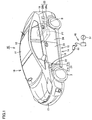
- Fig. 4 is a perspective view showing device body 52 on which cable unit 42 is mounted. As shown in Fig. 4 , device body 52 includes a fixing portion 55 and a rotating portion 56 provided rotatably with respect to this fixing portion 55.
- Rotating portion 56 includes a tube portion 57 formed in a tubular shape, a holding portion 58 provided within this tube portion 57 and holding control unit 44, a holding portion 59 holding plug 46, and a handle 65 provided in tube portion 57.
- Tube portion 57 is formed in the shape of a tube having a bottom, and provided rotatably about a rotation center line O with respect to fixing portion 55.
- Tube portion 57 includes a wall surface 61 and a circumferential wall portion 60 formed so as to rise from the circumferential edge of this wall surface 61.
- Tube portion 57 includes a first end and a second end that are arranged in the direction in which rotation center line O extends.
- the second end of tube portion 57 has a wall surface 61 and is provided with an opening 62.
- Circumferential wall portion 60 is provided with slits 63 and 64 that extend from the opening edge of opening 62 toward wall surface 61. Slits 63 and 64 are located so as to face each other across rotation center line O.
- Holding portion 58 is provided on wall surface 61 while holding portion 59 is provided on circumferential wall portion 60.
- Handle 65 is provided at the opening edge of opening 62, and the user can grip handle 65 to rotate tube portion 57 around rotation center line O.
- control unit 44 is held in holding portion 58, and cable 43 extending from control unit 44 is pulled out through slit 64 onto the outer circumferential surface of circumferential wall portion 60. Then, cable 43 is wound around the outer circumferential surface of circumferential wall portion 60 of cable 43.
- Fixing portion 55 includes a back surface wall 70 disposed on the first end side of tube portion 57, a flange portion 71 extending along the opening edge of opening 62, a plurality of coupling members 72 coupling flange portion 71 and back surface wall 70, and a guide plate 73, and a holding portion 74.
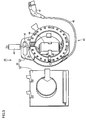
- Fig. 5 is a rear view of device body 52.
- back surface wall 70 includes a support plate 75, a gripping portion 76 protruding upward from the upper end of support plate 75, and a leg 79 formed in the lower end of support plate 75.
- Support plate 75 is formed so as to project outward as compared with the outer circumferential surface of circumferential wall portion 60 shown in Fig. 4 , and supports cable 43 wound around the outer circumferential surface of circumferential wall portion 60. Furthermore, support plate 75 supports tube portion 57 so as to be rotatable.
- Support plate 75 is provided with a recess 80, into which a protrusion of fixing plate 53 shown in Fig. 3 fits.
- Recess 80 is formed in the position on the surface of support plate 75, along which rotation center line O extends.
- Recess 80 has an inner surface including a circular bottom wall surface 82, and an inner circumferential surface 81 formed so as to rise from the outer circumference of bottom wall surface 82.
- Bottom wall surface 82 is formed in the shape of a circle centered at rotation center line O.
- a cross section of inner circumferential surface 81 in a plane perpendicular to rotation center line O is shaped as a circle centered at rotation center line O.
- a "circle centered at rotation center line O” includes a complete circle centered at rotation center line O, and a shape substantially recognized as a circle centered at rotation center line O.
- inner circumferential surface 81 is formed so as to vertically cross bottom wall surface 82 in the example shown in Fig. 5 , the shape of inner circumferential surface 81 is not limited thereto.
- inner circumferential surface 81 may be formed such that its diameter is decreased with increasing proximity to bottom wall surface 82, starting from opening of recess 80.
- Gripping portion 76 is formed so as to protrude upward from the upper end of support plate 75. Gripping portion 76 is provided with an insertion hole 77 through which a user's finger can be inserted, and a plurality of holes 78 through which a hook formed in fixing plate 53 shown in Fig. 3 is inserted.
- the user can grip gripping portion 76 by causing his/her finger to pass through insertion hole 77.
- the user can also move device body 52 by gripping the gripping portion 76 even in the state where cable unit 42 is mounted on device body 52.
- Leg 79 is formed on the lower end side of support plate 75, and has a prescribed length in the width direction of device body 52.
- flange portion 71 extends along the opening edge of opening 62, and is formed in an approximately annular shape.
- inner circumference edge 83 of flange portion 71 extends along the opening edge of opening 62. Accordingly, opening 62 is not covered by flange portion 71, but the inside of tube portion 57 is in communication with the outside through opening 62.
- Flange portion 71 is formed so as to project outward as compared with the outer circumferential surface of circumferential wall portion 60, and supports cable 43 wound around the outer circumferential surface of circumferential wall portion 60.
- Flange portion 71 is provided with a slit 85 formed so as to extend from inner circumference edge 83 of flange portion 71 to outer circumferential edge 84. Slit 85 is greater in width than cable 45.
- This slit 85 is formed so as to extend in the vertical direction at the time when device body 52 is free-standing on the imaginary flat plane.
- Flange portion 71 is provided with holding portion 74 for holding charging plug 41 of cable unit 42.
- Flange portion 71 is provided with a plurality of through holes 87 spaced apart from each other in the direction in which flange portion 71 extends. These through holes 87 are formed in flange portion 71 so as to be closer to outer circumferential edge 84 than to the outer circumferential surface of circumferential wall portion 60. Consequently, cable 43 wound around the outer circumferential surface of circumferential wall portion 60 is cooled by the air having passed through the through hole 87, so that a temperature rise at cable 43 can be suppressed.
- Guide plate 73 is formed in a part of outer circumferential edge 84 of flange portion 71.
- Guide plate 73 which extends along outer circumferential edge 84, serves to suppress disarrangement of cable 43 when cable 43 is pulled out and when cable 43 is wound up.
- a leg 88 is formed in the lower end of flange portion 71. Like leg 79, leg 88 is also formed so as to extend in the width direction of device body 52.
- leg 88 and leg 79 are installed on an imaginary flat plane, device body 52 can be free-standing. Accordingly, during use of charging device 40, device body 52 is removed from fixing plate 53, and can be free-standing on the ground surface.
- Coupling member 72 couples back surface wall 70 and flange portion 71 to each other.
- Coupling member 72 is formed on the outer circumferential edge 84 side of flange portion 71.
- a plurality of coupling members 72 are arranged so as to be spaced apart from each other along outer circumferential edge 84.
- this coupling member 72 is formed of a bolt and a nut, for example, and can disconnect flange portion 71 and back surface wall 70 from each other as appropriate.
- Fig. 6 is a perspective view showing the state where cable unit 42 is removed from device body 52.
- coupling member 72 is first removed from device body 52 in Fig. 5 .
- flange portion 71 is removed from device body 52.
- charging plug 41 is removed from holding portion 74
- control unit 44 is removed from holding portion 58.
- plug 46 is removed from holding portion 59, and cable 43 wound around rotating portion 56 is pulled out.
- Fig. 6 shows the state where flange portion 71 is fixed again to back surface wall 70 after cable unit 42 is removed from device body 52.
- Fig. 7 is a side view showing a handle 65 and its surroundings.
- handle 65 includes an arm 90 and a knob portion 91 provided at the end of arm 90.
- Arm 90 is connected to the opening edge of opening 62 of rotating portion 56 shown in Fig. 4 .
- Fig. 8 is a cross-sectional view showing knob portion 91.
- Knob portion 91 includes a hollow outer frame portion 92, and an alternate switch 98 provided within this outer frame portion 92.
- Alternate switch 98 functions as a holding mechanism for selectively limiting the rotation of rotating portion 56 with respect to fixing portion 55.
- Alternate switch 98 includes a hollow shaft portion 93, a hollow shaft portion 94 disposed within this shaft portion 93 and having a hollow portion 95 formed therewithin, a rotating cam 96 disposed within hollow shaft portion 94, and a spring 97.
- Outer frame portion 92 is provided so as to be rotatable with respect to shaft portion 93.
- Hollow shaft portion 94 is provided so as to be slidable within shaft portion 93 in both directions including a direction D1 and a direction D2.
- direction D1 the end of hollow shaft portion 94 is inserted into through hole 87 shown in Fig. 7 .
- the end of hollow shaft portion 94 inserted into through hole 87 slides in direction D2, hollow shaft portion 94 is pulled out from through hole 87.
- Spring 97 biases hollow shaft portion 94 in direction D2. Thereby, hollow shaft portion 94 is biased by spring 97 so as to be inserted into shaft portion 93.
- Rotating cam 96 is provided rotatably with respect to shaft portion 93.
- Shaft portion 93 is formed in an oval shape and provided on its both ends with groove portions. These groove portions each are formed so as to receive the protrusion formed within hollow portion 95 of hollow shaft portion 94.
- knob portion 91 when a user presses hollow shaft portion 94 in direction D1, rotating cam 96 and a protrusion formed within hollow portion 95 engage with each other, thereby fixing the position of hollow shaft portion 94 in the state where hollow shaft portion 94 protrudes from shaft portion 93 in direction D1.
- Handle 65 is coupled to rotating portion 56 shown in Fig. 4 . Accordingly, when hollow shaft portion 94 is inserted into through hole 87, rotating portion 56 is held in flange portion 71 and thereby prevented from rotating. In this way, hollow shaft portion 94 of alternate switch 98 functions as a stopper for holding rotating portion 56 in fixing portion 55.
- a plurality of through holes 87 are provided so as to be spaced apart from each other in the direction in which flange portion 71 extends. Accordingly, when the user appropriately selects through hole 87 into which hollow shaft portion 94 is inserted, the relative positional relationship between tube portion 57 and fixing portion 55 can be adjusted to fix tube portion 57 to fixing portion 55.
- Fig. 9 is a perspective view showing fixing plate 53.
- fixing plate 53 includes a fixing plate 100 formed in a plate shape, a hook 101 formed on the upper end side of fixing plate 100, a protrusion 102 formed in the center portion of fixing plate 100, and a receiving portion 103 formed on the lower end side of fixing plate 100.
- Protrusion 102 is formed in a cylindrical shape or circular truncated cone shape, for example.
- Protrusion 102 includes an upper surface 104 formed in a circular shape, and a circumferential surface 105 extending from the circumferential edge of upper surface 104 toward fixing plate 100.
- a center line O1 shown in the figure passes through the center point on upper surface 104.
- the cross section of upper surface 104 in a plane perpendicular to center line O1 is shaped as a circle centered at center line O1.
- the circle centered at center line O1 also includes a circle centered at center line O1, and a shape substantially regarded as a circle centered at center line O1.
- Fig. 10 is a diagram schematically showing the state where device body 52 is mounted on fixing plate 53. As shown in Fig. 10 , in the state where device body 52 is mounted on fixing plate 53, hook 101 of fixing plate 53 passes through a hole 78 formed in device body 52. Protrusion 102 of fixing plate 53 fits into a recess 80 formed in device body 52. Receiving portion 103 receives leg 79.
- Circumferential surface 105 of protrusion 102 is in contact with inner circumferential surface 81 of recess 80 while upper surface 104 of protrusion 102 is in contact with bottom wall surface 82 of recess 80.
- the friction force generated between upper surface 104 and bottom wall surface 82 is uniformly distributed between upper surface 104 and bottom wall surface 82.
- the friction force generated between circumferential surface 105 and inner circumferential surface 81 is also uniformly distributed between circumferential surface 105 and inner circumferential surface 81.
- FIGs. 11 to 13 each illustrate a method of use in the state where device body 52 is removed from fixing plate 53.
- Fig. 11 is a perspective view showing the state where cable 43 is wound around device body 52.
- plug 46 is held in holding portion 59 while control unit 44 is held in holding portion 58.
- Cable 43 is pulled out from within rotating portion 56 onto the outer circumferential surface of rotating portion 56, and further wound around the circumferential surface of rotating portion 56.
- Charging plug 41 is held in holding portion 74.
- charging plug 41 is removed from holding portion 74.
- cable 43 is pulled out from device body 52.
- rotating portion 56 rotates.
- control unit 44 is held in rotating portion 56, and therefore, also rotates in accordance with the rotation of rotating portion 56.
- rotating portion 56 is positioned with respect to fixing portion 55 such that slit 63 and slit 85 are brought into communication with each other. Then, rotating portion 56 is fixed to fixing portion 55 by handle 65.
- a user's hand is inserted through the opening of rotating portion 56 to grip plug 46. Then, plug 46 is pulled out from rotating portion 56 and cable 45 is caused to pass through pull-out passage 86. Consequently, plug 46 extends above device body 52. Then, plug 46 is connected to a power supply, and charging plug 41 is connected to charging unit 21 of the vehicle.
- charging plug 41 is mounted on holding portion 74
- plug 46 is mounted on holding portion 59.
- coupling member 72 is removed and flange portion 71 is removed from back surface wall 70.
- control unit 44 is mounted on holding portion 58 and plug 46 is mounted on holding portion 59.
- cable 43 is caused to pass through slit 64.
- flange portion 71 is fixed to back surface wall 70 by coupling member 72.
- handle 65 is rotated to wind up cable 43 around the outer circumferential surface of rotating portion 56.
- charging plug 41 is mounted on holding portion 74. In this way, cable unit 42 is housed in device body 52.
- the present invention is suitable for a cable winding device.
Landscapes
- Engineering & Computer Science (AREA)
- Power Engineering (AREA)
- Transportation (AREA)
- Mechanical Engineering (AREA)
- Life Sciences & Earth Sciences (AREA)
- Sustainable Development (AREA)
- Sustainable Energy (AREA)
- Electric Propulsion And Braking For Vehicles (AREA)
- Charge And Discharge Circuits For Batteries Or The Like (AREA)
- Storing, Repeated Paying-Out, And Re-Storing Of Elongated Articles (AREA)
Applications Claiming Priority (1)
| Application Number | Priority Date | Filing Date | Title |
|---|---|---|---|
| PCT/JP2011/071845 WO2013046290A1 (ja) | 2011-09-26 | 2011-09-26 | ケーブル巻取り装置 |
Publications (3)
| Publication Number | Publication Date |
|---|---|
| EP2763257A1 EP2763257A1 (en) | 2014-08-06 |
| EP2763257A4 EP2763257A4 (en) | 2015-03-25 |
| EP2763257B1 true EP2763257B1 (en) | 2016-05-11 |
Family
ID=47994409
Family Applications (1)
| Application Number | Title | Priority Date | Filing Date |
|---|---|---|---|
| EP11873024.1A Not-in-force EP2763257B1 (en) | 2011-09-26 | 2011-09-26 | Cable winding device |
Country Status (5)
| Country | Link |
|---|---|
| US (1) | US9260023B2 (ja) |
| EP (1) | EP2763257B1 (ja) |
| JP (1) | JP5737414B2 (ja) |
| CN (1) | CN103828162B (ja) |
| WO (1) | WO2013046290A1 (ja) |
Cited By (1)
| Publication number | Priority date | Publication date | Assignee | Title |
|---|---|---|---|---|
| DE102020208899B3 (de) * | 2020-07-16 | 2021-05-20 | Volkswagen Aktiengesellschaft | Haspel mit einem Gehäuse und einem Leitungsmittel sowie Gehäuse für eine Haspel |
Families Citing this family (22)
| Publication number | Priority date | Publication date | Assignee | Title |
|---|---|---|---|---|
| WO2013008329A1 (ja) * | 2011-07-14 | 2013-01-17 | トヨタ自動車株式会社 | 充電用ケーブル収容装置 |
| JP5737414B2 (ja) * | 2011-09-26 | 2015-06-17 | トヨタ自動車株式会社 | ケーブル巻取り装置 |
| JP5877108B2 (ja) * | 2011-11-09 | 2016-03-02 | 中央発條株式会社 | ケーブル収容装置 |
| JP2013157147A (ja) * | 2012-01-27 | 2013-08-15 | Chuo Spring Co Ltd | 充電ケーブル用収容装置 |
| JP2013179817A (ja) * | 2012-01-31 | 2013-09-09 | Chuo Spring Co Ltd | 充電ケーブル用収容装置 |
| US20140284160A1 (en) * | 2013-03-15 | 2014-09-25 | Jimmy Ray Towe | Dc tool cable reel |
| DE102013221652A1 (de) * | 2013-10-24 | 2015-04-30 | Bayerische Motoren Werke Aktiengesellschaft | Tragbares Ladekabel zum Laden eines Energiespeichers eines elektrisch betriebenen Fahrzeugs |
| US20150325994A1 (en) | 2014-05-09 | 2015-11-12 | Ruggedreel Inc. | System and apparatus for electrically coupling to a cable on a rotatable reel using a torsional spring |
| US9346653B1 (en) * | 2014-11-20 | 2016-05-24 | Shenzhen Mindray Bio-Medical Electronics Co., Ltd. | Cord retractor |
| JP6294903B2 (ja) * | 2016-03-22 | 2018-03-14 | 株式会社Subaru | 車両 |
| US10446978B2 (en) * | 2017-03-21 | 2019-10-15 | Logan Bailey | Cable management system for storing and managing an adapter box and cable |
| CN106956611B (zh) * | 2017-04-04 | 2018-09-21 | 兰州锦阳新能源科技有限公司 | 一种新型新能源电动汽车直流充电桩 |
| US20180290868A1 (en) * | 2017-04-05 | 2018-10-11 | David R. Hall | Portable Hoisting Apparatus |
| CN207090700U (zh) * | 2017-05-27 | 2018-03-13 | 上海齐迈五金有限公司 | 一种多功能卷线盘 |
| US20190006064A1 (en) * | 2017-06-29 | 2019-01-03 | David R. Hall | Power Drop Assembly |
| NL1042631B1 (en) * | 2017-11-07 | 2019-05-13 | A Pot | Reel device |
| DE102018210227A1 (de) * | 2018-06-22 | 2019-12-24 | Schill GmbH & Co. KG | Kabeltrommel |
| JP6856587B2 (ja) * | 2018-08-20 | 2021-04-07 | 矢崎総業株式会社 | フラットケーブル巻取装置及びその組立方法 |
| DE102018131934A1 (de) | 2018-12-12 | 2020-07-02 | Volkswagen Aktiengesellschaft | Kabelaufrollvorrichtung für ein elektrisches Kraftfahrzeug-Ladekabel sowie Anordnung eines Kraftfahrzeug-Ladekabels an einer solchen Kabelaufrollvorrichtung |
| EP3838657A1 (de) * | 2019-12-20 | 2021-06-23 | ConWys AG | Ladeboxsystem |
| CN112172557B (zh) * | 2020-08-13 | 2021-10-26 | 大连海洋大学 | 一种新能源充电用收卷式充电接头 |
| CN112037976B (zh) * | 2020-08-31 | 2022-04-01 | 江苏天源电缆有限公司 | 一种轻质节能电缆及其电缆桥架 |
Family Cites Families (19)
| Publication number | Priority date | Publication date | Assignee | Title |
|---|---|---|---|---|
| US2801303A (en) * | 1953-01-19 | 1957-07-30 | Grace N Pailing | Cord reel |
| JPS5554695Y2 (ja) * | 1976-03-26 | 1980-12-17 | ||
| JPS52128968A (en) | 1976-04-22 | 1977-10-28 | Sumitomo Chemical Co | Method of vacuum evaporation |
| US4282954A (en) * | 1980-02-11 | 1981-08-11 | Hill John O | Rewinder device |
| JPS61162217U (ja) | 1985-03-28 | 1986-10-07 | ||
| US4725697A (en) * | 1986-08-28 | 1988-02-16 | Alert Stamping & Mfg. Co., Inc. | Extension cord reel and case |
| CA2086589A1 (en) * | 1992-12-31 | 1994-07-01 | David Martin Fonseka | Portable retractable extension cord |
| US6273354B1 (en) * | 1999-06-03 | 2001-08-14 | Alert Stamping & Mfg. Co., Inc. | Retracting extension cord reel |
| US6170775B1 (en) * | 1999-06-03 | 2001-01-09 | Alert Stamping & Mfg. Co., Inc. | Electrical cord reel |
| US7114603B2 (en) * | 2004-12-02 | 2006-10-03 | Li-Chun Lai | Extension cord holder |
| US7438258B2 (en) * | 2006-01-18 | 2008-10-21 | Chi-Wen Chen | Reel device for winding an electrical cable thereon |
| US8074916B2 (en) * | 2008-02-01 | 2011-12-13 | Applied Optical Systems, Inc. | Fiber optic/electrical cable reel assembly |
| JP2010052861A (ja) | 2008-08-26 | 2010-03-11 | Panasonic Electric Works Co Ltd | 電気自動車充電用コードセット |
| WO2010023527A2 (en) | 2008-08-26 | 2010-03-04 | Panasonic Electric Works Co., Ltd. | Electric vehicle charging cord set |
| WO2010041319A1 (ja) * | 2008-10-09 | 2010-04-15 | トヨタ自動車株式会社 | 接続装置 |
| JP5362367B2 (ja) | 2009-01-09 | 2013-12-11 | 株式会社アルファ | 充電ケーブルの連結構造 |
| JP5414319B2 (ja) | 2009-03-23 | 2014-02-12 | 日東工業株式会社 | 充電装置 |
| US7984798B1 (en) * | 2009-12-31 | 2011-07-26 | John Ernest Hall | Electric cord reel |
| JP5737414B2 (ja) * | 2011-09-26 | 2015-06-17 | トヨタ自動車株式会社 | ケーブル巻取り装置 |
-
2011
- 2011-09-26 JP JP2013535651A patent/JP5737414B2/ja active Active
- 2011-09-26 WO PCT/JP2011/071845 patent/WO2013046290A1/ja active Application Filing
- 2011-09-26 US US14/344,170 patent/US9260023B2/en active Active
- 2011-09-26 CN CN201180073673.4A patent/CN103828162B/zh not_active Expired - Fee Related
- 2011-09-26 EP EP11873024.1A patent/EP2763257B1/en not_active Not-in-force
Cited By (1)
| Publication number | Priority date | Publication date | Assignee | Title |
|---|---|---|---|---|
| DE102020208899B3 (de) * | 2020-07-16 | 2021-05-20 | Volkswagen Aktiengesellschaft | Haspel mit einem Gehäuse und einem Leitungsmittel sowie Gehäuse für eine Haspel |
Also Published As
| Publication number | Publication date |
|---|---|
| JPWO2013046290A1 (ja) | 2015-03-26 |
| CN103828162A (zh) | 2014-05-28 |
| JP5737414B2 (ja) | 2015-06-17 |
| US20140339039A1 (en) | 2014-11-20 |
| EP2763257A4 (en) | 2015-03-25 |
| US9260023B2 (en) | 2016-02-16 |
| CN103828162B (zh) | 2016-01-20 |
| EP2763257A1 (en) | 2014-08-06 |
| WO2013046290A1 (ja) | 2013-04-04 |
Similar Documents
| Publication | Publication Date | Title |
|---|---|---|
| EP2763257B1 (en) | Cable winding device | |
| JP5673798B2 (ja) | コード収容装置および車両 | |
| EP2735467B1 (en) | Vehicle | |
| WO2011064855A1 (ja) | 車両 | |
| WO2010041319A1 (ja) | 接続装置 | |
| JP5668855B2 (ja) | 充電装置 | |
| JP5472408B2 (ja) | 取出装置 | |
| US9231343B2 (en) | Inlet | |
| US9166428B2 (en) | Charging device | |
| JP2010268593A (ja) | 車両 | |
| JP2014050301A (ja) | ケーブルホルダ |
Legal Events
| Date | Code | Title | Description |
|---|---|---|---|
| PUAI | Public reference made under article 153(3) epc to a published international application that has entered the european phase |
Free format text: ORIGINAL CODE: 0009012 |
|
| 17P | Request for examination filed |
Effective date: 20140422 |
|
| AK | Designated contracting states |
Kind code of ref document: A1 Designated state(s): AL AT BE BG CH CY CZ DE DK EE ES FI FR GB GR HR HU IE IS IT LI LT LU LV MC MK MT NL NO PL PT RO RS SE SI SK SM TR |
|
| DAX | Request for extension of the european patent (deleted) | ||
| A4 | Supplementary search report drawn up and despatched |
Effective date: 20150225 |
|
| RIC1 | Information provided on ipc code assigned before grant |
Ipc: H02G 11/02 20060101AFI20150219BHEP Ipc: B65H 75/44 20060101ALI20150219BHEP Ipc: B65H 75/40 20060101ALI20150219BHEP Ipc: B60L 11/18 20060101ALI20150219BHEP |
|
| RIC1 | Information provided on ipc code assigned before grant |
Ipc: B60L 11/14 20060101ALI20151027BHEP Ipc: B60L 11/18 20060101ALI20151027BHEP Ipc: B65H 75/44 20060101ALI20151027BHEP Ipc: H02G 11/02 20060101AFI20151027BHEP Ipc: B65H 75/40 20060101ALI20151027BHEP Ipc: B60L 11/12 20060101ALI20151027BHEP |
|
| GRAP | Despatch of communication of intention to grant a patent |
Free format text: ORIGINAL CODE: EPIDOSNIGR1 |
|
| INTG | Intention to grant announced |
Effective date: 20151223 |
|
| GRAS | Grant fee paid |
Free format text: ORIGINAL CODE: EPIDOSNIGR3 |
|
| GRAA | (expected) grant |
Free format text: ORIGINAL CODE: 0009210 |
|
| AK | Designated contracting states |
Kind code of ref document: B1 Designated state(s): AL AT BE BG CH CY CZ DE DK EE ES FI FR GB GR HR HU IE IS IT LI LT LU LV MC MK MT NL NO PL PT RO RS SE SI SK SM TR |
|
| REG | Reference to a national code |
Ref country code: GB Ref legal event code: FG4D |
|
| REG | Reference to a national code |
Ref country code: CH Ref legal event code: EP |
|
| REG | Reference to a national code |
Ref country code: AT Ref legal event code: REF Ref document number: 799336 Country of ref document: AT Kind code of ref document: T Effective date: 20160515 |
|
| REG | Reference to a national code |
Ref country code: IE Ref legal event code: FG4D |
|
| REG | Reference to a national code |
Ref country code: DE Ref legal event code: R084 Ref document number: 602011026641 Country of ref document: DE |
|
| REG | Reference to a national code |
Ref country code: DE Ref legal event code: R096 Ref document number: 602011026641 Country of ref document: DE |
|
| REG | Reference to a national code |
Ref country code: GB Ref legal event code: 746 Effective date: 20160629 |
|
| REG | Reference to a national code |
Ref country code: FR Ref legal event code: PLFP Year of fee payment: 6 |
|
| REG | Reference to a national code |
Ref country code: LT Ref legal event code: MG4D |
|
| REG | Reference to a national code |
Ref country code: NL Ref legal event code: MP Effective date: 20160511 |
|
| PG25 | Lapsed in a contracting state [announced via postgrant information from national office to epo] |
Ref country code: LT Free format text: LAPSE BECAUSE OF FAILURE TO SUBMIT A TRANSLATION OF THE DESCRIPTION OR TO PAY THE FEE WITHIN THE PRESCRIBED TIME-LIMIT Effective date: 20160511 Ref country code: FI Free format text: LAPSE BECAUSE OF FAILURE TO SUBMIT A TRANSLATION OF THE DESCRIPTION OR TO PAY THE FEE WITHIN THE PRESCRIBED TIME-LIMIT Effective date: 20160511 Ref country code: NL Free format text: LAPSE BECAUSE OF FAILURE TO SUBMIT A TRANSLATION OF THE DESCRIPTION OR TO PAY THE FEE WITHIN THE PRESCRIBED TIME-LIMIT Effective date: 20160511 Ref country code: NO Free format text: LAPSE BECAUSE OF FAILURE TO SUBMIT A TRANSLATION OF THE DESCRIPTION OR TO PAY THE FEE WITHIN THE PRESCRIBED TIME-LIMIT Effective date: 20160811 |
|
| REG | Reference to a national code |
Ref country code: AT Ref legal event code: MK05 Ref document number: 799336 Country of ref document: AT Kind code of ref document: T Effective date: 20160511 |
|
| PG25 | Lapsed in a contracting state [announced via postgrant information from national office to epo] |
Ref country code: HR Free format text: LAPSE BECAUSE OF FAILURE TO SUBMIT A TRANSLATION OF THE DESCRIPTION OR TO PAY THE FEE WITHIN THE PRESCRIBED TIME-LIMIT Effective date: 20160511 Ref country code: SE Free format text: LAPSE BECAUSE OF FAILURE TO SUBMIT A TRANSLATION OF THE DESCRIPTION OR TO PAY THE FEE WITHIN THE PRESCRIBED TIME-LIMIT Effective date: 20160511 Ref country code: GR Free format text: LAPSE BECAUSE OF FAILURE TO SUBMIT A TRANSLATION OF THE DESCRIPTION OR TO PAY THE FEE WITHIN THE PRESCRIBED TIME-LIMIT Effective date: 20160812 Ref country code: ES Free format text: LAPSE BECAUSE OF FAILURE TO SUBMIT A TRANSLATION OF THE DESCRIPTION OR TO PAY THE FEE WITHIN THE PRESCRIBED TIME-LIMIT Effective date: 20160511 Ref country code: LV Free format text: LAPSE BECAUSE OF FAILURE TO SUBMIT A TRANSLATION OF THE DESCRIPTION OR TO PAY THE FEE WITHIN THE PRESCRIBED TIME-LIMIT Effective date: 20160511 Ref country code: PT Free format text: LAPSE BECAUSE OF FAILURE TO SUBMIT A TRANSLATION OF THE DESCRIPTION OR TO PAY THE FEE WITHIN THE PRESCRIBED TIME-LIMIT Effective date: 20160912 Ref country code: RS Free format text: LAPSE BECAUSE OF FAILURE TO SUBMIT A TRANSLATION OF THE DESCRIPTION OR TO PAY THE FEE WITHIN THE PRESCRIBED TIME-LIMIT Effective date: 20160511 |
|
| PG25 | Lapsed in a contracting state [announced via postgrant information from national office to epo] |
Ref country code: IT Free format text: LAPSE BECAUSE OF FAILURE TO SUBMIT A TRANSLATION OF THE DESCRIPTION OR TO PAY THE FEE WITHIN THE PRESCRIBED TIME-LIMIT Effective date: 20160511 |
|
| PG25 | Lapsed in a contracting state [announced via postgrant information from national office to epo] |
Ref country code: CZ Free format text: LAPSE BECAUSE OF FAILURE TO SUBMIT A TRANSLATION OF THE DESCRIPTION OR TO PAY THE FEE WITHIN THE PRESCRIBED TIME-LIMIT Effective date: 20160511 Ref country code: DK Free format text: LAPSE BECAUSE OF FAILURE TO SUBMIT A TRANSLATION OF THE DESCRIPTION OR TO PAY THE FEE WITHIN THE PRESCRIBED TIME-LIMIT Effective date: 20160511 Ref country code: EE Free format text: LAPSE BECAUSE OF FAILURE TO SUBMIT A TRANSLATION OF THE DESCRIPTION OR TO PAY THE FEE WITHIN THE PRESCRIBED TIME-LIMIT Effective date: 20160511 Ref country code: RO Free format text: LAPSE BECAUSE OF FAILURE TO SUBMIT A TRANSLATION OF THE DESCRIPTION OR TO PAY THE FEE WITHIN THE PRESCRIBED TIME-LIMIT Effective date: 20160511 Ref country code: SK Free format text: LAPSE BECAUSE OF FAILURE TO SUBMIT A TRANSLATION OF THE DESCRIPTION OR TO PAY THE FEE WITHIN THE PRESCRIBED TIME-LIMIT Effective date: 20160511 |
|
| REG | Reference to a national code |
Ref country code: DE Ref legal event code: R097 Ref document number: 602011026641 Country of ref document: DE |
|
| PG25 | Lapsed in a contracting state [announced via postgrant information from national office to epo] |
Ref country code: AT Free format text: LAPSE BECAUSE OF FAILURE TO SUBMIT A TRANSLATION OF THE DESCRIPTION OR TO PAY THE FEE WITHIN THE PRESCRIBED TIME-LIMIT Effective date: 20160511 Ref country code: SM Free format text: LAPSE BECAUSE OF FAILURE TO SUBMIT A TRANSLATION OF THE DESCRIPTION OR TO PAY THE FEE WITHIN THE PRESCRIBED TIME-LIMIT Effective date: 20160511 Ref country code: BE Free format text: LAPSE BECAUSE OF NON-PAYMENT OF DUE FEES Effective date: 20160511 Ref country code: PL Free format text: LAPSE BECAUSE OF FAILURE TO SUBMIT A TRANSLATION OF THE DESCRIPTION OR TO PAY THE FEE WITHIN THE PRESCRIBED TIME-LIMIT Effective date: 20160511 |
|
| PLBE | No opposition filed within time limit |
Free format text: ORIGINAL CODE: 0009261 |
|
| STAA | Information on the status of an ep patent application or granted ep patent |
Free format text: STATUS: NO OPPOSITION FILED WITHIN TIME LIMIT |
|
| 26N | No opposition filed |
Effective date: 20170214 |
|
| PG25 | Lapsed in a contracting state [announced via postgrant information from national office to epo] |
Ref country code: MC Free format text: LAPSE BECAUSE OF FAILURE TO SUBMIT A TRANSLATION OF THE DESCRIPTION OR TO PAY THE FEE WITHIN THE PRESCRIBED TIME-LIMIT Effective date: 20160511 |
|
| REG | Reference to a national code |
Ref country code: CH Ref legal event code: PL |
|
| PG25 | Lapsed in a contracting state [announced via postgrant information from national office to epo] |
Ref country code: SI Free format text: LAPSE BECAUSE OF FAILURE TO SUBMIT A TRANSLATION OF THE DESCRIPTION OR TO PAY THE FEE WITHIN THE PRESCRIBED TIME-LIMIT Effective date: 20160511 |
|
| REG | Reference to a national code |
Ref country code: IE Ref legal event code: MM4A |
|
| PG25 | Lapsed in a contracting state [announced via postgrant information from national office to epo] |
Ref country code: LI Free format text: LAPSE BECAUSE OF NON-PAYMENT OF DUE FEES Effective date: 20160930 Ref country code: CH Free format text: LAPSE BECAUSE OF NON-PAYMENT OF DUE FEES Effective date: 20160930 Ref country code: IE Free format text: LAPSE BECAUSE OF NON-PAYMENT OF DUE FEES Effective date: 20160926 |
|
| REG | Reference to a national code |
Ref country code: FR Ref legal event code: PLFP Year of fee payment: 7 |
|
| PG25 | Lapsed in a contracting state [announced via postgrant information from national office to epo] |
Ref country code: LU Free format text: LAPSE BECAUSE OF NON-PAYMENT OF DUE FEES Effective date: 20160926 |
|
| PG25 | Lapsed in a contracting state [announced via postgrant information from national office to epo] |
Ref country code: HU Free format text: LAPSE BECAUSE OF FAILURE TO SUBMIT A TRANSLATION OF THE DESCRIPTION OR TO PAY THE FEE WITHIN THE PRESCRIBED TIME-LIMIT; INVALID AB INITIO Effective date: 20110926 |
|
| PG25 | Lapsed in a contracting state [announced via postgrant information from national office to epo] |
Ref country code: IS Free format text: LAPSE BECAUSE OF FAILURE TO SUBMIT A TRANSLATION OF THE DESCRIPTION OR TO PAY THE FEE WITHIN THE PRESCRIBED TIME-LIMIT Effective date: 20160511 Ref country code: CY Free format text: LAPSE BECAUSE OF FAILURE TO SUBMIT A TRANSLATION OF THE DESCRIPTION OR TO PAY THE FEE WITHIN THE PRESCRIBED TIME-LIMIT Effective date: 20160511 Ref country code: MK Free format text: LAPSE BECAUSE OF FAILURE TO SUBMIT A TRANSLATION OF THE DESCRIPTION OR TO PAY THE FEE WITHIN THE PRESCRIBED TIME-LIMIT Effective date: 20160511 Ref country code: MT Free format text: LAPSE BECAUSE OF NON-PAYMENT OF DUE FEES Effective date: 20160930 |
|
| PG25 | Lapsed in a contracting state [announced via postgrant information from national office to epo] |
Ref country code: BG Free format text: LAPSE BECAUSE OF FAILURE TO SUBMIT A TRANSLATION OF THE DESCRIPTION OR TO PAY THE FEE WITHIN THE PRESCRIBED TIME-LIMIT Effective date: 20160511 |
|
| REG | Reference to a national code |
Ref country code: FR Ref legal event code: PLFP Year of fee payment: 8 |
|
| PG25 | Lapsed in a contracting state [announced via postgrant information from national office to epo] |
Ref country code: AL Free format text: LAPSE BECAUSE OF FAILURE TO SUBMIT A TRANSLATION OF THE DESCRIPTION OR TO PAY THE FEE WITHIN THE PRESCRIBED TIME-LIMIT Effective date: 20160511 Ref country code: TR Free format text: LAPSE BECAUSE OF FAILURE TO SUBMIT A TRANSLATION OF THE DESCRIPTION OR TO PAY THE FEE WITHIN THE PRESCRIBED TIME-LIMIT Effective date: 20160511 |
|
| PGFP | Annual fee paid to national office [announced via postgrant information from national office to epo] |
Ref country code: FR Payment date: 20210812 Year of fee payment: 11 |
|
| PGFP | Annual fee paid to national office [announced via postgrant information from national office to epo] |
Ref country code: DE Payment date: 20210818 Year of fee payment: 11 Ref country code: GB Payment date: 20210818 Year of fee payment: 11 |
|
| REG | Reference to a national code |
Ref country code: DE Ref legal event code: R119 Ref document number: 602011026641 Country of ref document: DE |
|
| GBPC | Gb: european patent ceased through non-payment of renewal fee |
Effective date: 20220926 |
|
| PG25 | Lapsed in a contracting state [announced via postgrant information from national office to epo] |
Ref country code: FR Free format text: LAPSE BECAUSE OF NON-PAYMENT OF DUE FEES Effective date: 20220930 Ref country code: DE Free format text: LAPSE BECAUSE OF NON-PAYMENT OF DUE FEES Effective date: 20230401 |
|
| PG25 | Lapsed in a contracting state [announced via postgrant information from national office to epo] |
Ref country code: GB Free format text: LAPSE BECAUSE OF NON-PAYMENT OF DUE FEES Effective date: 20220926 |