EP2762437A2 - Système de treuil à câble - Google Patents
Système de treuil à câble Download PDFInfo
- Publication number
- EP2762437A2 EP2762437A2 EP14153557.5A EP14153557A EP2762437A2 EP 2762437 A2 EP2762437 A2 EP 2762437A2 EP 14153557 A EP14153557 A EP 14153557A EP 2762437 A2 EP2762437 A2 EP 2762437A2
- Authority
- EP
- European Patent Office
- Prior art keywords
- warning device
- winch assembly
- cable
- winch
- traction means
- Prior art date
- Legal status (The legal status is an assumption and is not a legal conclusion. Google has not performed a legal analysis and makes no representation as to the accuracy of the status listed.)
- Withdrawn
Links
- 230000011664 signaling Effects 0.000 claims abstract description 3
- 238000011084 recovery Methods 0.000 claims description 19
- 230000004913 activation Effects 0.000 claims description 18
- 230000003287 optical effect Effects 0.000 claims description 15
- 230000001788 irregular Effects 0.000 claims description 5
- 230000000694 effects Effects 0.000 claims description 3
- 238000012544 monitoring process Methods 0.000 claims description 3
- 238000000605 extraction Methods 0.000 claims description 2
- 230000001939 inductive effect Effects 0.000 claims description 2
- 230000001960 triggered effect Effects 0.000 claims 1
- 238000011161 development Methods 0.000 description 10
- 230000018109 developmental process Effects 0.000 description 10
- 230000002349 favourable effect Effects 0.000 description 8
- 208000027418 Wounds and injury Diseases 0.000 description 4
- 238000003306 harvesting Methods 0.000 description 4
- 230000008901 benefit Effects 0.000 description 3
- 230000001419 dependent effect Effects 0.000 description 3
- 230000005236 sound signal Effects 0.000 description 3
- 230000005540 biological transmission Effects 0.000 description 2
- 230000006378 damage Effects 0.000 description 2
- 230000009849 deactivation Effects 0.000 description 2
- 208000014674 injury Diseases 0.000 description 2
- 238000005096 rolling process Methods 0.000 description 2
- 239000002023 wood Substances 0.000 description 2
- 108010076504 Protein Sorting Signals Proteins 0.000 description 1
- 230000004888 barrier function Effects 0.000 description 1
- 238000002485 combustion reaction Methods 0.000 description 1
- 238000009472 formulation Methods 0.000 description 1
- 238000012423 maintenance Methods 0.000 description 1
- 238000000034 method Methods 0.000 description 1
- 239000000203 mixture Substances 0.000 description 1
- 230000001681 protective effect Effects 0.000 description 1
- 238000001454 recorded image Methods 0.000 description 1
- 230000008439 repair process Effects 0.000 description 1
- 208000037974 severe injury Diseases 0.000 description 1
- 230000009528 severe injury Effects 0.000 description 1
- 230000001502 supplementing effect Effects 0.000 description 1
- 230000000007 visual effect Effects 0.000 description 1
Images
Classifications
-
- B—PERFORMING OPERATIONS; TRANSPORTING
- B66—HOISTING; LIFTING; HAULING
- B66D—CAPSTANS; WINCHES; TACKLES, e.g. PULLEY BLOCKS; HOISTS
- B66D1/00—Rope, cable, or chain winding mechanisms; Capstans
- B66D1/28—Other constructional details
- B66D1/40—Control devices
- B66D1/42—Control devices non-automatic
- B66D1/46—Control devices non-automatic electric
-
- B—PERFORMING OPERATIONS; TRANSPORTING
- B66—HOISTING; LIFTING; HAULING
- B66D—CAPSTANS; WINCHES; TACKLES, e.g. PULLEY BLOCKS; HOISTS
- B66D1/00—Rope, cable, or chain winding mechanisms; Capstans
- B66D1/54—Safety gear
Definitions
- the invention relates to a winch assembly, in particular on a rescue or rear-end vehicle and equipped with the winch assembly rescue or rear-mounted vehicle.
- ropes or other traction means are used. These are attached to the object to be rescued, in particular on the log, for example, wrapped in this or wrapped around this. After pressing a winch drive then the object to be rescued, that is, in particular the log, moved to the mountain or rear vehicle.
- the traction device gets under tension. by virtue of its that the traction means used, that is, the ropes, in particular wire ropes or straps are only very poorly visible and the objects are pulled over long distances, is only one in the area between the object to be rescued and the recovery vehicle hard-to-see barrier formed by the taut rope.
- the object of the present invention is therefore to provide a possibility to inform people in the vicinity of a winch assembly early on that a winch assembly is in operation. Furthermore, a possibility should be created to display the course and the condition of the traction device.
- the cable winch arrangement according to the invention can be attached to a rescue or rear vehicle.
- a rescue vehicle can be used, for example, to move objects which are not movable by conventional means out of their position.
- Under a rear-view vehicle is a, in particular used in the timber harvesting vehicle, which serves to pull the felled tree trunks from the stock and deliver to a discharge point for the logs.
- the cable winch arrangement according to the invention comprises a cable drum and a traction means which can be raised or lowered into or onto the cable drum or can be ejected from the cable drum.
- This traction means has a hook at one end, a chain or eyelet on which an attachment of the object to be rescued, for example, a log is provided.
- the cable winch assembly comprises a winch drive, via which a retraction of the traction means can take place on or in the cable drum.
- the winch drive can have an internal combustion engine.
- the drive can also be integrated into a drive for the recovery vehicle.
- the winch assembly according to the invention is characterized in that a warning device is provided.
- the warning device signals an operating state of the cable winch arrangement. For example, when the winch drive is activated via the warning device, a signal can be transmitted.
- the situation is also a danger in which the traction means is ejected from the cable drum or unwound from the cable drum when the drive is activated, without actually supplying the traction means to the object to be rescued.
- larger cable lengths can run off the cable drum and accumulate in the area in front of the cable winch arrangement. If the traction device is then pulled back into the cable drum or wound onto it, unforeseen problems can occur, since the operator does not get an overview of how much traction device was unwound from the cable drum.
- the suddenly moving, because on the rope drum raised Traction means a not inconsiderable accident potential for in the area of non-tensioned traction devices people.
- An embodiment of the cable winch arrangement according to the invention provides that the winch drive is designed as a rotary drive for the cable drum.
- the rotary drive is switched off in particular automatically or by an operator switched off. This then results in the possibility that an activation of the warning signal or signal only takes place when the rotary drive, or when the brake drive is activated for the cable drum / is.
- the brake drive for the cable drum prevents slipping back or drifting of the object to be rescued or trunk wood.
- the cable winch assembly has a first mode of operation in which the traction means is extended or unwound from the cable drum, and a second mode of operation wherein the traction means is retracted or retracted into or onto the cable drum.
- Both operating states are signaled accordingly via the warning device.
- the warning device There is the possibility that when rolling up another signal is output, for example a signal in a different color or with a different frequency or tone sequence than when pulling out.
- the greater potential for danger in this case comes from the traction means under train, which is why a signaling of the operating state in which the traction means in or on the cable drum is wound on or is of particular importance.
- the signal is formed as an optical warning signal.
- This can already be detected from afar and thus optimally fulfills the warning function.
- Care is taken in particular that the optical signal in the signal frequency or in the signal color or intensity of the operating environment of the cable winch arrangement drops sharply, so that here actually an optical stimulus is created, which is fast and already recognizable from afar.
- the signal is formed as an acoustic warning signal, which is emitted, for example, from a horn or siren.
- the frequency or volume of the warning signal is selected such that it is well audible even when operating noise of the used rear or recovery vehicles and carries over long distances, so that an early warning of the winch assembly or the rear or recovery vehicle approaching persons he follows.
- a signal output via radio is also conceivable.
- An advantageous embodiment of the winch assembly according to the invention provides that the warning device with the winch assembly is releasably firmly connected.
- the warning device is arranged at an arrangement point for the cable winch assembly or the cable drum, in particular on a winch assembly supporting mountain or rear-end vehicle or a rear plate. This allows the replacement of the cable winch assembly, without having to replace the warning device with this or to have to remove. An upgrade of the vehicle is thus possible in a simple manner. Also arise from the separate arrangement of warning device and winch assembly advantages in the maintenance and repair of both the winch assembly, as well as the warning device.
- the warning device is arranged in the region of the end of the traction device carrying the hook, the chain or the eye or directly on the hook, the chain or the eye.
- the warning device is then not in the area of the cable winch arrangement, or the cable drum or the drive on the rear or recovery vehicle, but directly to the object to be rescued.
- the warning signal is not only pointed to the traction means by the warning signal is, but also on the hanging object, for example, a tree trunk, from which itself can also pose a significant risk when it dissolves, for example, the hook, the chain or the eyelet.
- the warning device is designed as a lamp which emits flashes of light or emits permanent light at regular or irregular time intervals.
- a frequency can be selected that is perceived by an approaching person even with strong other optical ambient stimuli.
- a certain easily perceptible frequency of the emitted light flashes, or a color or intensity of the light flashes or the signal can be selected, which is perceived as easily visible and thus shows the desired hinting function.
- Long lamp life and low power consumption is achieved by using an LED as the light source.
- the lamp can also be provided as an element that can be arranged on the operator or their clothing.
- such a lamp can be attached to the working helmet in the field of vision of the operator.
- a lamp on the control unit for the vehicle, on a radio, a remote control or as an attachable or attachable element to the clothing, eg. In the manner of a sticker.
- warning device is formed with an acoustic signal, it is considered favorable if the device emits sound signals at regular or irregular time intervals. These are then in volume, frequency and intensity, or duration chosen such that even in a noisy work environment with put into operation mountain or rear-end vehicle, the sound signal is loud and clearly audible. An output of radio signals is also conceivable.
- a further preferred embodiment of the cable winch arrangement provides that a pulsed or permanent mechanical warning signal, in particular a vibration, is emitted via the warning device.
- a pulsed or permanent mechanical warning signal in particular a vibration
- the winch assembly is in operation and traction means of the cable drum off or is rolled out of this.
- the different warning signal forms are combined.
- an acoustic can be combined with an optical signal.
- a mechanical signal is combined with an optical or acoustic and / or a radio signal or all three signal forms are present next to one another.
- the intensity of the vibration is adjustable.
- the winch assembly according to the invention is characterized in particular by the fact that a remote control is provided for the winch assembly.
- a remote control is provided for the winch assembly.
- the use of a remote control for the cable winch assembly allows an operator to pull the rope to the object to be rescued, for example a log, and then to operate the winch assembly from the article to be rescued. Simultaneously with the commissioning of the winch assembly can then be carried out via the remote control and activation of the warning device. It proves to be advantageous if an automatic activation takes place as soon as the cable winch arrangement or the drive provided there is put into operation, for example by operation via the remote control.
- an activation by the operator of the winch assembly takes place independently of the activation of the cable winch arrangement.
- a separate control device be provided on the remote or winch assembly to implement this embodiment.
- the warning device can be activated.
- the warning device is necessarily activated with activation of the cable winch assembly or the drive. There is thus no possibility to bypass or to forget the warning signal or its transmission.
- a power supply of the warning device is preferably carried out via the cable winch assembly, the winch assembly supporting mountain or rear vehicle and / or the traction means itself.
- the warning device has an independent power supply.
- the use of a rechargeable battery proves to be advantageous in this context.
- the recharging can take place, for example, by means of a photovoltaic module which is assigned to the warning device itself or to the cable winch arrangement and / or the return or recovery vehicle.
- a charging device for the warning device is arranged on the mountain or rear-mounted vehicle or in the region of the arrangement point for the winch assembly.
- the charging of the battery provided in the warning device takes place in particular when in contact with the charging device.
- the charging device is designed as an inductive charging device and thus made no connection between the warning device and charging device must be to achieve a battery charge. This proves to be particularly advantageous especially in the pollution-prone environment of mountain or rear-end vehicles.
- the warning device is formed in a part considered advantageous in further development of the winch assembly.
- a first part of the warning device for example a first light or a first sound emitting element is provided in the area of the cable winch assembly or the arrangement point for the winch assembly, while a second part in the region of the hook, the chain or the eye bearing end of Pull means or directly on the hook, the chain or the eyelet is arranged. From this embodiment of the winch assembly then both beginning, and end of the traction means can be seen and it can be derived from the position of the respective warning devices, the course of the traction means.
- both parts of the warning device are designed to be remotely operated, it is considered favorable if the parts of the warning device independently or jointly, in particular by an emitted from the winch assembly and / or the remote pulse can be activated ,
- the traction means itself is part of the warning device.
- the traction means may have an optical marking, in particular a self-luminous, fluorescent or reflective signal marking.
- the signal marking can be woven or incorporated, for example, in the traction means itself, so that a self-luminous traction means is available.
- the traction means of the winch assembly is preferably formed as a chain, rope or band.
- a development of the winch assembly which can be combined at any time with one of the embodiments described above or is to be regarded as an independent embodiment, provides that the warning device has a transmitter for a control signal. It is provided that via the control signal to the remote control or an operator assignable warning device, in particular a an optical, acoustic and / or mechanical signal issuing warning device can be activated. It is provided that the output of the control signal takes place when the warning device is activated, for example via the operation of the remote control or by an output from the winch assembly itself activation signal. The additional warning device complements the warning device described above. It is provided that a signal output during the activity of the winch drive and / or during the extraction or retraction of the traction device takes place. The warning device outputs a signal which is formed as a continuous tone, tone sequence, continuous light, sequence of light flashes or via pulsed or permanent vibration or as a radio signal.
- a preferred embodiment of the cable winch assembly with additional warning device provides that the warning device is integrated in the remote control or an operating lever on the remote control or the winch assembly or is designed as additional, portable by the operator on the body or clothing warning device.
- Background of the device supplementing or forming the warning device is that during operation of the winch assembly, the operator receives no indication of whether the winch drive is activated or deactivated due to lack of visual contact. While this is typically signaled via the warning device, if the operator is in an off-center position and has no direct line of sight with the warning device, it is difficult for him to determine if the winch drive is activated and the traction means ejected from the cable drum or wound on this.
- the warning device which in particular serves the protection and safety of the operator, informs the operator of the operating state of the cable winch arrangement, in particular whether the winch drive is activated or deactivated. Only after deactivation, a further signal or control signal is output, which deactivates the warning device and causes an end of the signal output. If the warning device is integrated in the remote control or an operating lever or designed as a single signal generator, the signal is permanently output by the latter while the winch drive is activated or the traction means are being rolled out or rolled up.
- the warning device can also be designed as a wearable or attachable or bag-portable body, for example, which emits a vibration while the winch assembly is activated.
- the execution with mechanical signal that is, as a vibrating warning device, proves to be advantageous when working in a noisy environment in which light or sound signals can be easily overlooked or overheard.
- the warning device or at least the part that can be worn on the body or the clothing is designed as a vibration generator or vibration generator.
- the vibration generator or generator can also be worn or arranged directly on the body, ie on the skin or underwear.
- the warning device or the vibration module is an embodiment of the warning device or the vibration module as a handset, cuff, pendant on a chain, amulet, ring, hoop or the like for wearing on the body suitable element, eg. Like a badge.
- the ejection of the traction means can be signaled by a different signal or a signal sequence than curling.
- a rescue or rear-end vehicle which has a cable winch arrangement as described above and thus significantly better characterizes the course of a traction device and thus reduces the risk of accidents and injuries by traction under tension or under train traction means.
- the winch assembly, or provided on the winch assembly warning device is formed preferably remote controlled in this context. It follows that without direct contact with the mountain or rear vehicle activation of both the winch assembly, as well as the warning device can be performed, for example, when the operator is in the area of the object to be rescued, for example, a log and the remote control the winch assembly and thus also want to activate the warning device.
- mountain or rear vehicle in an embodiment considered advantageous or development that not only a remote control, but also on the mountains or rear vehicle itself a control for the winch assembly and the warning device is present.
- This makes it possible for an operator to activate the cable winch arrangement directly from the rear or recovery vehicle and, with this or in addition to this, to carry out a connection of the warning device.
- the mountain or rear vehicle according to the invention is characterized in a development considered favorable by the fact that a tilt sensor is arranged on the winch assembly, the cable drum and / or an arrangement point for the cable winch arrangement.
- a tilt sensor is arranged on the winch assembly, the cable drum and / or an arrangement point for the cable winch arrangement.
- the recovery or return vehicle or the respective arrangement point for the inclination sensor while the activation of the warning device is provided.
- a movement of the mountain or rear-end vehicle proves to be disadvantageous and dangerous because the entire mountain or rear vehicle can slip off.
- the warning device thus receives a further additional function, namely a warning of dangers emanating from the rescue or return vehicle itself during operation of the winch assembly.
- An additional, as advantageous and favorable viewed embodiment of the mountain or rear vehicle provides that a camera is arranged on this or on the winch assembly, which allows a video remote monitoring of the traction means or the recovery or recovery process.
- the remote operator thus always has the opportunity to learn about the condition of the winch assembly or the location and condition of the traction device.
- the camera can detect the entire area, which is traversed by the traction means, and pass this information to the operator. This can thus also be in poorly visible positions and operate the winch assembly via a remote control, but has constantly the danger area, that is, the area in which the traction device runs, in view and can intervene in time, as soon as further dangers or accident situations arise ,
- the remote control is associated with a display or a display for displaying the images taken by the camera.
- a development of such equipped mountain or rear-view vehicle that a unit for storing and transmitting the images recorded by the camera is provided.
- the sending of the images or the issuance of warning signals can advantageously take place via a radio or telecommunications connection.
- the recorded images or the warning signal are sent to a mobile device, and the operator thus a remote monitoring of the winch assembly, the rescue or rear-end vehicle or the traction means or attached thereto, to be sheltered or to be backed object is enabled.
- the warning device can also be designed as part of a radio system and thus provides the ability to remain independent of existing telecommunications networks.
- warning device can also be used for issuing emergency signals via radio or mobile networks and thus provides multiple benefits.
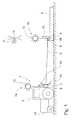
- Fig. 1 shows a rescue or rear vehicle 2 having an embodiment of the winch assembly 1 according to the invention.
- the cable drum 3 is arranged, which in the embodiment not shown drive, which can be designed as a rotary drive for the cable drum 3 or as a brake drive for this purpose assigned is.
- the traction means 6 can be fed or rolled up on the cable drum 3.
- the traction means 6 serves to draw an object 5 to be rescued, in the exemplary embodiment a tree trunk, in the direction of the rear or recovery vehicle 2.
- an eyelet 4 is provided, which is connected to a hook 16 which is hammered into the article 5 and thus allows the pulling of the article 5.
- a warning device 7a which in the exemplary embodiment has a lamp 10 which emits a warning signal in regular or irregular sections as soon as the drive for the cable drum 3 is activated. If the drive is taken as a rotary drive for the cable drum 3 in operation, that is, a retraction of the traction means 6 or a rolling, the traction means 6 comes under tension and is taut. From this moment results in a potential hazard to the traction means 6 approaching persons.
- the warning device 7a is activated immediately upon activation of the drive for the cable drum 3 and an optical signal is transmitted.
- the first warning device 7a opposite, that is, arranged on the eyelet 4 at the end 9 of the traction means 6 is located in the embodiment, a further, second warning device 7b, which is also equipped with a lamp 10. From the two signals, which may be the same or differently timed luminous results for an approaching person an indication of the course of the traction means 6, or an indication that a traction device 6 is in operation and thus an increased risk potential consists.
- the winch assembly 1, as well as the warning device 7a, b can be operated remotely.
- the warning device 7a, b has a receiver 15.
- An operator 12, who carries out the activation of the winch assembly 1, has a remote control 11, via which an activation of the winch assembly 1, that is in particular, a connection or disconnection of the drive of the cable drum 3 can be made.
- a signal can be emitted via the remote control 11, which activates the warning device 7a, b and causes the lamps 10 to emit an optical signal.
- the signal emitted by the remote control 11 is received by the receiver 15 and thereby activates the warning device 7a, b.
- the warning device 7a, b shown here can be supplemented by a warning device (not shown).
- a warning device (not shown).
- This picks up signals emitted by the warning device 7a, b and then in turn activates an additional signal, for example a sound or light signal or a vibration, which indicates that the cable winch arrangement is in operation. Only after deactivation of the winch drive also ends the output of the additional signal. The operator 12 is therefore always informed about the operation of the winch drive. An unintentional long unwinding or pulling the traction means 6 can thus be prevented, or the operator is reminded that the drive is still in operation.
- warning device 7a, b outputs an acoustic or mechanical signal.
- the combination of optical, acoustic and mechanical signal is equally possible and encompassed by the invention.
- the rear or recovery vehicle 2 has in the embodiment of Fig. 1 via a rear shield 14, against which the object 5 is pulled.
- the traction means 6 is guided by the rear shield 14.
- the warning device 7a, b is provided in the embodiment at an arrangement point 8 for the cable drum 3 and the winch assembly 1. Of course, there is the possibility that the warning device 7a, b is also attached to the rear shield 14.
- Fig. 1 is the rear attachment of the entire device. Equally possible, conceivable and covered by the invention is of course also an attachment to the front 17 of the recovery vehicle 2. The invention is not limited to the embodiment with remote control 11. Equally conceivable, possible and encompassed by the invention is a control of both the warning device 7a, b, as well as the winch assembly 1 from the mountains or rear vehicle 2 from.
- the arranged at the end of the cable 9 warning device 7b is preferably formed battery powered.
- the power supply to the mountains or rear vehicle 2 arranged warning device 7a can be done via the on-board electronics of mountain or rear vehicle 2.
- a charger associated with the winch assembly 1 or warning device 7a can be used to charge the battery provided in the second, separate part of the warning device 7b with the traction means 6 retracted.
- the inventive in the Fig. 1 illustrated in one embodiment, a way to prevent accidents when recovering objects 5 and this particular back of logs in the forest area, there on the intended warning device 7a, b, which also - as in Fig. 1 seen - may be formed in two parts, an early reference to the tensioned or exciting traction means 6 is carried out so that the winch assembly 1 approaching persons are warned in good time and thus can bypass the danger spot far. Security is also increased for persons involved in a harvesting activity, since the attention is drawn to the danger site, so that potential risks can be circumvented.
Landscapes
- Engineering & Computer Science (AREA)
- Mechanical Engineering (AREA)
- Emergency Alarm Devices (AREA)
- Emergency Lowering Means (AREA)
Applications Claiming Priority (1)
| Application Number | Priority Date | Filing Date | Title |
|---|---|---|---|
| DE201320100480 DE202013100480U1 (de) | 2013-02-01 | 2013-02-01 | Seilwindenanordnung |
Publications (2)
| Publication Number | Publication Date |
|---|---|
| EP2762437A2 true EP2762437A2 (fr) | 2014-08-06 |
| EP2762437A3 EP2762437A3 (fr) | 2014-09-17 |
Family
ID=50030130
Family Applications (1)
| Application Number | Title | Priority Date | Filing Date |
|---|---|---|---|
| EP14153557.5A Withdrawn EP2762437A3 (fr) | 2013-02-01 | 2014-01-31 | Système de treuil à câble |
Country Status (2)
| Country | Link |
|---|---|
| EP (1) | EP2762437A3 (fr) |
| DE (1) | DE202013100480U1 (fr) |
Cited By (1)
| Publication number | Priority date | Publication date | Assignee | Title |
|---|---|---|---|---|
| DE102017214398A1 (de) * | 2017-08-18 | 2019-02-21 | Jenoptik Advanced Systems Gmbh | Handsteuergerät zum Bedienen einer Seilwinde, Seilwindensystem und Verfahren zum Informieren eines Bedieners einer Seilwinde mittels eines Handsteuergeräts |
Family Cites Families (15)
| Publication number | Priority date | Publication date | Assignee | Title |
|---|---|---|---|---|
| US2745633A (en) * | 1953-06-22 | 1956-05-15 | Claire L Cornwell | Cable speed indicator |
| US2776814A (en) * | 1953-10-09 | 1957-01-08 | Hubert A Sparks | Drum movement indicator |
| DE1743108U (de) * | 1955-06-03 | 1957-04-11 | Ernst Rotzler K G Maschf | Seilwinde zum anbau an ein kraftfahrzeug, insbesondere am heck eines ackerschleppers. |
| AT279454B (de) * | 1967-08-21 | 1970-03-10 | Rolandia Gmbh | Vorrichtung zum Hochschrappen von Schüttgütern an eine Stau- oder Aufnahmevorrichtung |
| US3922605A (en) * | 1974-12-11 | 1975-11-25 | Koehring Co | Electrical winch drum rotation indicating system |
| DE3916558A1 (de) * | 1989-01-20 | 1990-07-26 | Gewerk Eisenhuette Westfalia | Einrichtung zur absperrung einer wandoeffnung in schottwaenden, schutzdaemmen u. dgl. |
| JPH075113Y2 (ja) * | 1993-04-19 | 1995-02-08 | 日本電話施設株式会社 | 車両用エンジンの緊急停止装置 |
| DE10018153A1 (de) * | 2000-04-12 | 2001-10-18 | Ralph Schneider | Selbstbergungshilfe für Kraftfahrzeuge |
| DE10203763A1 (de) * | 2002-01-25 | 2003-08-14 | Kaessbohrer Gelaendefahrzeug | Windeneinheit für ein Pistenfahrzeug |
| DE10207880C1 (de) * | 2002-02-21 | 2003-07-31 | Demag Cranes & Components Gmbh | Steuereinrichtung zum Steuern eines Hebezeugs |
| CN101132161A (zh) * | 2006-08-23 | 2008-02-27 | 麦尔马克汽车电子(深圳)有限公司 | 马达控制器及其控制方法 |
| CN101488020B (zh) * | 2008-01-18 | 2012-01-11 | 大禾电子(深圳)有限公司 | 有线遥控器及其控制方法 |
| AT508123B1 (de) * | 2009-07-22 | 2010-11-15 | Schardax Christian Dipl Ing Fh | Neigungssensitives überwachungsmodul für funkferngesteuerte forstseilwinden |
| DE102010007603A1 (de) * | 2010-02-05 | 2011-08-11 | Kässbohrer Geländefahrzeug AG, 88471 | Arbeitsfahrzeug |
| DE202010011345U1 (de) * | 2010-08-11 | 2010-10-21 | Terex Demag Gmbh | Überwachungs- und Warneinrichtung an Baumaschinen |
-
2013
- 2013-02-01 DE DE201320100480 patent/DE202013100480U1/de not_active Expired - Lifetime
-
2014
- 2014-01-31 EP EP14153557.5A patent/EP2762437A3/fr not_active Withdrawn
Non-Patent Citations (1)
| Title |
|---|
| None |
Cited By (1)
| Publication number | Priority date | Publication date | Assignee | Title |
|---|---|---|---|---|
| DE102017214398A1 (de) * | 2017-08-18 | 2019-02-21 | Jenoptik Advanced Systems Gmbh | Handsteuergerät zum Bedienen einer Seilwinde, Seilwindensystem und Verfahren zum Informieren eines Bedieners einer Seilwinde mittels eines Handsteuergeräts |
Also Published As
| Publication number | Publication date |
|---|---|
| EP2762437A3 (fr) | 2014-09-17 |
| DE202013100480U1 (de) | 2014-05-05 |
Similar Documents
| Publication | Publication Date | Title |
|---|---|---|
| DE102011115161A1 (de) | Anzeigevorrichtung für einen Ladezustand einer Kraftfahrzeug-Traktionsbatterie | |
| DE102010028988A1 (de) | Sicherheitsvorrichtung zur Vermeidung von Auffahrunfällen, Fahrzeug und Verfahren | |
| EP2762437A2 (fr) | Système de treuil à câble | |
| DE102004053163A1 (de) | Individual-Warngerät eines Rottenwarnsystems | |
| WO1999026808A1 (fr) | Systeme et dispositif de securite, ainsi que procede approprie ameliorant la securite | |
| DE3625812A1 (de) | Signalvorrichtung fuer schiffbruechige | |
| DE202004013455U1 (de) | Notfallhilfe | |
| DE102019202460A1 (de) | Warnschutzausrüstung sowie System und Verfahren zur Erkennung einer Warnschutzausrüstung | |
| DE4219894A1 (de) | Notrufsystem zur Sicherheitsüberwachung einer Person | |
| DE69315545T2 (de) | Optische Warneinrichtung | |
| DE102019209739A1 (de) | Warneinrichtungsanordnung zur Anordnung in oder an einem Fahrzeug | |
| DE202019001030U1 (de) | Signal- und Warnweste mit Anzeigeelementen zum Zwecke der optischen Signalisierung von Fahrsituationen nach StVO | |
| DE102013110213A1 (de) | Routenzuganhänger mit Personenschutzsystem | |
| DE10035686A1 (de) | Zusatz-Sicherheitsleuchteneinrichtung für Straßenfahrzeuge | |
| DE102011084681A1 (de) | Bekleidungsstück | |
| EP3780981A1 (fr) | Chaussure de détection d'obstacle | |
| DE202008008311U1 (de) | Rettungsballon | |
| DE202020002714U1 (de) | Ausziehbarer Lichtschlauch als Seitenmarkierungsleuchte für Fahrzeugkombinationen mit Nachläufern | |
| DE202007002063U1 (de) | Warnleuchtdreieck | |
| DE225793C (fr) | ||
| DE202018102130U1 (de) | Schuh zur Hinderniserkennung | |
| DE102018133085A1 (de) | Rettungsballonsystem | |
| DE202006019330U1 (de) | Sicherungseinrichtung für Zweiradfahrer | |
| DE10259573B4 (de) | Warnvorrichtung | |
| DE29908875U1 (de) | Handwerkzeug mit Leuchtmittel |
Legal Events
| Date | Code | Title | Description |
|---|---|---|---|
| PUAI | Public reference made under article 153(3) epc to a published international application that has entered the european phase |
Free format text: ORIGINAL CODE: 0009012 |
|
| 17P | Request for examination filed |
Effective date: 20140131 |
|
| AK | Designated contracting states |
Kind code of ref document: A2 Designated state(s): AL AT BE BG CH CY CZ DE DK EE ES FI FR GB GR HR HU IE IS IT LI LT LU LV MC MK MT NL NO PL PT RO RS SE SI SK SM TR |
|
| AX | Request for extension of the european patent |
Extension state: BA ME |
|
| PUAL | Search report despatched |
Free format text: ORIGINAL CODE: 0009013 |
|
| AK | Designated contracting states |
Kind code of ref document: A3 Designated state(s): AL AT BE BG CH CY CZ DE DK EE ES FI FR GB GR HR HU IE IS IT LI LT LU LV MC MK MT NL NO PL PT RO RS SE SI SK SM TR |
|
| AX | Request for extension of the european patent |
Extension state: BA ME |
|
| RIC1 | Information provided on ipc code assigned before grant |
Ipc: B66D 1/54 20060101ALI20140814BHEP Ipc: B66D 1/46 20060101AFI20140814BHEP |
|
| STAA | Information on the status of an ep patent application or granted ep patent |
Free format text: STATUS: THE APPLICATION IS DEEMED TO BE WITHDRAWN |
|
| 18D | Application deemed to be withdrawn |
Effective date: 20150318 |