EP2762274B1 - Method of polishing back surface of substrate and substrate processing apparatus - Google Patents
Method of polishing back surface of substrate and substrate processing apparatus Download PDFInfo
- Publication number
- EP2762274B1 EP2762274B1 EP14020010.6A EP14020010A EP2762274B1 EP 2762274 B1 EP2762274 B1 EP 2762274B1 EP 14020010 A EP14020010 A EP 14020010A EP 2762274 B1 EP2762274 B1 EP 2762274B1
- Authority
- EP
- European Patent Office
- Prior art keywords
- polishing
- substrate
- back surface
- wafer
- center
- Prior art date
- Legal status (The legal status is an assumption and is not a legal conclusion. Google has not performed a legal analysis and makes no representation as to the accuracy of the status listed.)
- Active
Links
Images


Classifications
-
- B—PERFORMING OPERATIONS; TRANSPORTING
- B24—GRINDING; POLISHING
- B24B—MACHINES, DEVICES, OR PROCESSES FOR GRINDING OR POLISHING; DRESSING OR CONDITIONING OF ABRADING SURFACES; FEEDING OF GRINDING, POLISHING, OR LAPPING AGENTS
- B24B21/00—Machines or devices using grinding or polishing belts; Accessories therefor
- B24B21/004—Machines or devices using grinding or polishing belts; Accessories therefor using abrasive rolled strips
-
- B—PERFORMING OPERATIONS; TRANSPORTING
- B24—GRINDING; POLISHING
- B24B—MACHINES, DEVICES, OR PROCESSES FOR GRINDING OR POLISHING; DRESSING OR CONDITIONING OF ABRADING SURFACES; FEEDING OF GRINDING, POLISHING, OR LAPPING AGENTS
- B24B21/00—Machines or devices using grinding or polishing belts; Accessories therefor
- B24B21/04—Machines or devices using grinding or polishing belts; Accessories therefor for grinding plane surfaces
- B24B21/06—Machines or devices using grinding or polishing belts; Accessories therefor for grinding plane surfaces involving members with limited contact area pressing the belt against the work, e.g. shoes sweeping across the whole area to be ground
-
- B—PERFORMING OPERATIONS; TRANSPORTING
- B24—GRINDING; POLISHING
- B24B—MACHINES, DEVICES, OR PROCESSES FOR GRINDING OR POLISHING; DRESSING OR CONDITIONING OF ABRADING SURFACES; FEEDING OF GRINDING, POLISHING, OR LAPPING AGENTS
- B24B37/00—Lapping machines or devices; Accessories
- B24B37/04—Lapping machines or devices; Accessories designed for working plane surfaces
- B24B37/042—Lapping machines or devices; Accessories designed for working plane surfaces operating processes therefor
-
- B—PERFORMING OPERATIONS; TRANSPORTING
- B24—GRINDING; POLISHING
- B24B—MACHINES, DEVICES, OR PROCESSES FOR GRINDING OR POLISHING; DRESSING OR CONDITIONING OF ABRADING SURFACES; FEEDING OF GRINDING, POLISHING, OR LAPPING AGENTS
- B24B37/00—Lapping machines or devices; Accessories
- B24B37/27—Work carriers
- B24B37/30—Work carriers for single side lapping of plane surfaces
-
- B—PERFORMING OPERATIONS; TRANSPORTING
- B24—GRINDING; POLISHING
- B24B—MACHINES, DEVICES, OR PROCESSES FOR GRINDING OR POLISHING; DRESSING OR CONDITIONING OF ABRADING SURFACES; FEEDING OF GRINDING, POLISHING, OR LAPPING AGENTS
- B24B7/00—Machines or devices designed for grinding plane surfaces on work, including polishing plane glass surfaces; Accessories therefor
- B24B7/20—Machines or devices designed for grinding plane surfaces on work, including polishing plane glass surfaces; Accessories therefor characterised by a special design with respect to properties of the material of non-metallic articles to be ground
- B24B7/22—Machines or devices designed for grinding plane surfaces on work, including polishing plane glass surfaces; Accessories therefor characterised by a special design with respect to properties of the material of non-metallic articles to be ground for grinding inorganic material, e.g. stone, ceramics, porcelain
- B24B7/228—Machines or devices designed for grinding plane surfaces on work, including polishing plane glass surfaces; Accessories therefor characterised by a special design with respect to properties of the material of non-metallic articles to be ground for grinding inorganic material, e.g. stone, ceramics, porcelain for grinding thin, brittle parts, e.g. semiconductors, wafers
Definitions
- the present invention relates to a method of polishing a back surface of a substrate, such as a wafer.
- the present invention also relates to a substrate processing apparatus for polishing the back surface of the substrate.
- CMOS complimentary metal-oxide-semiconductor
- the aforementioned foreign matters may also be attached to a back surface of the wafer (i.e., a bare silicon surface). If such foreign matters are attached to the back surface of the wafer, the wafer may be separated from a stage reference surface of an exposure apparatus, or a front surface of the wafer may be inclined with respect to the stage reference surface, resulting in a patterning shift or a focal length error. In order to prevent such problems, it is necessary to remove the foreign matters from the back surface of the wafer.
- US 2011/0312247 A1 discloses a polishing device and method for polishing a rear surface of a substrate and a system including the polishing device.
- the substrate is polished by the substrate polishing unit in accordance with information acquired from a prior process performed prior to the polishing process of the rear surface of the substrate at the substrate polishing unit.
- the substrate polishing unit polishes the substrate within a polishing area determined on the basis of information acquired from a prior process.
- the polishing is performed by using any one or all of a plurality of substrate polishing units.
- One of the polishing units is configured to polish the back surface of the substrate while holding a bevel portion of the same.
- the present invention has been made in view of the above issues. It is therefore an object of the present invention to provide a method and an apparatus which can remove foreign matters from an entire back surface of a substrate, such as a wafer, at a high removal rate.
- a polishing method as set forth in Claim 1 and a substrate processing apparatus as set forth in Claim 10 are provided. Further embodiments are inter alia claimed in the dependent claims.
- a polishing method to polish the back surface of a substrate in its entirety including: placing a polishing tool in sliding contact with an outer circumferential region of a back surface of a substrate while holding a center-side region of the back surface of the substrate; and placing a polishing tool in sliding contact with the center-side region of the back surface of the substrate while holding a bevel portion of the substrate to polish the back surface.
- the placing the polishing tool in sliding contact with the outer circumferential region may be performed prior to the placing the polishing tool in sliding contact with the center-side region.
- a substrate processing apparatus includes: a first back-surface polishing unit configured to place a polishing tool in sliding contact with an outer circumferential region of a back surface of a substrate while holding a center-side region of the back surface of the substrate to polish the outer circumferential region; a second back-surface polishing unit configured to place a polishing tool in sliding contact with the center-side region while holding a bevel portion of the substrate to polish the center-side region; and a transfer robot configured to transport the substrate between the first back-surface polishing unit and the second back-surface polishing unit.
- the first back-surface polishing unit may be configured to polish the outer circumferential region before the second back-surface polishing unit polishes the center-side region.
- the transfer robot may be configured to invert the substrate that has been polished by the first back-surface polishing unit and transport the inverted substrate to the second back-surface polishing unit.
- the polishing tool is placed in sliding contact with the back surface of the substrate to thereby scrape away the back surface slightly. Therefore, the foreign matters can be removed from the back surface at a high removal rate. In particular, the foreign matters can be removed from the entire back surface of the substrate by placing the polishing tool in sliding contact with the back surface in its entirety.
- a polishing method is constituted by a first polishing process and a second polishing process.
- the first polishing process is a process of polishing an outer circumferential region of a back surface of a substrate
- the second polishing process is a process of polishing a center-side region of the back surface of the substrate.
- the center-side region is a region including a center of the substrate
- the outer circumferential region is a region lying radially outwardly of the center-side region.
- the center-side region adjoins the outer circumferential region, and a combination of the center-side region and the outer circumferential region covers the back surface of the substrate in its entirety. More specifically, an outermost part of the center-side region and an innermost part of the outer circumferential region are connected to each other to cover the back surface in its entirety.
- FIG. 1A and FIG. 1B are enlarged cross sectional views each showing a peripheral portion of a wafer which is an example of the substrate. More specifically, FIG. 1A is a cross-sectional view of a so-called straight type wafer, and FIG. 1B is a cross-sectional view of a so-called round type wafer.
- the back surface of the wafer i.e., the substrate
- a peripheral round surface of the wafer is called a bevel portion.
- the back surface of the wafer is the flat surface which is located radially inwardly of the bevel portion.
- the outer circumferential region of the back surface of the wafer adjoins the bevel portion.
- the outer circumferential region is an annular region having a width of ten-odd millimeters
- the center-side region is a circular region lying inside the outer circumferential region.
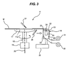
- FIG. 2 is a schematic view showing a first back-surface polishing unit 11 for polishing the outer circumferential region of the back surface of the wafer W.
- This first back-surface polishing unit 11 has a first substrate holder 12 for holding and rotating the wafer (i.e., substrate) W, and a first polishing head 14 for pressing a polishing tool against the back surface of the wafer W when held by the first substrate holder 12.
- the first substrate holder 12 has a substrate stage 17 configured to hold the wafer W by vacuum suction, and a motor 19 configured to rotate the substrate stage 17.
- the wafer W is placed on the substrate stage 17 with the back surface of the wafer W facing downward.
- a groove 17a is formed on a top surface of the substrate stage 17, and this groove 17a communicates with a vacuum line 20.
- the vacuum line 20 is coupled to a vacuum source (e.g., a vacuum pump) which is not shown in the figures.
- a vacuum is created in the groove 17a of the substrate stage 17 through the vacuum line 20
- the wafer W is held on the substrate stage 17 by a vacuum suction force.
- the motor 19 rotates the substrate stage 17 to thereby rotate the wafer W around its axis.
- the substrate stage 17 is smaller than a diameter of the wafer W, and the center-side region of the back surface of the wafer W is held by the substrate stage 17.
- the outer circumferential region of the back surface of the wafer W protrudes outwardly from the substrate stage 17.
- the first polishing head 14 is arranged adjacent to the substrate stage 17. More specifically, the first polishing head 14 is located so as to face the exposed outer circumferential region of the back surface of the wafer W.
- the first polishing head 14 has a plurality of rollers 23 which support a polishing tape 22 serving as the polishing tool, a pressing member 24 for pressing the polishing tape 22 against the back surface of the wafer W, and a pneumatic cylinder 25 as an actuator for applying a pressing force to the pressing member 24.
- the pneumatic cylinder 25 applies the pressing force to the pressing member 24, so that the pressing member 24 presses the polishing tape 22 against the back surface of the wafer W.
- a grindstone may be used as the polishing tool.
- polishing tape 22 One end of the polishing tape 22 is connected to a feeding reel 31, and the other end is connected to a take-up reel 32.
- the polishing tape 22 is advanced at a predetermined speed from the feeding reel 31 to the take-up reel 32 via the first polishing head 14.
- Examples of the polishing tape 22 to be used include a tape having abrasive grains fixed to a surface thereof, and a tape constituted by a hard nonwoven fabric.
- the first polishing head 14 is coupled to a polishing head moving mechanism 35. This polishing head moving mechanism 35 is configured to move the first polishing head 14 outwardly in the radial direction of the wafer W.
- the polishing head moving mechanism 35 may be constructed by a combination of a ball screw and a servomotor.
- Liquid supply nozzles 37, 38 for supplying a polishing liquid onto the wafer W are arranged above and below the wafer W which is held by the substrate stage 17. Pure water may be used as the polishing liquid. This is for the reason that use of a polishing liquid containing a chemical component having an etching action may enlarge a recess formed on the back surface of the wafer W.
- the outer circumferential region of the back surface of the wafer W is polished as follows.
- the wafer W, which is held on the substrate stage 17, is rotated about its axis by the motor 19, and the polishing liquid is supplied from the liquid supply nozzles 37, 38 to a front surface and the back surface of the rotating wafer W.
- the first polishing head 14 presses the polishing tape 22 against the back surface of the wafer W.
- the polishing tape 22 is placed in sliding contact with the outer circumferential region to thereby polish the outer circumferential region.
- the polishing head moving mechanism 35 moves the first polishing head 14 outwardly in the radial direction of the wafer W at a predetermined speed as indicated by arrow shown in FIG.
- the wafer W is removed from the first back-surface polishing unit 11 by a transfer robot which is not shown in the figures.
- the transfer robot inverts the wafer W so that the back surface of the wafer W faces upward, and transports the inverted wafer W to a second back-surface polishing unit which will be explained below.
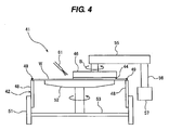
- FIG. 4 is a schematic view showing the second back-surface polishing unit for polishing the center-side region of the back surface of the wafer W
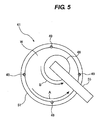
- FIG. 5 is a plan view of the second back-surface polishing unit.
- the second back-surface polishing unit 41 has a second substrate holder 42 configured to hold and rotate the wafer W, and a second polishing head 46 configured to press a polishing tool 44 against the back surface of the wafer W.
- the second substrate holder 42 has a plurality of chucks 48 for holding a bevel portion of the wafer W, and further has a hollow motor 51 for rotating these chucks 48 around the axis of the wafer W.
- Each chuck 48 has a clamp 49 at its upper end, and the bevel portion of the wafer W is gripped by this clamp 49.
- the hollow motor 51 rotates the chucks 48 to thereby rotate the wafer W around its axis as indicated by arrow A shown in FIG. 5 .
- the wafer W is held by the second substrate holder 42 with the back surface of the wafer W facing upward.
- the lower surface (i.e., the surface opposite to the back surface) of the wafer W, which is held by the chucks 48, is supported by a substrate supporting member 52.
- This substrate supporting member 52 is coupled to the hollow motor 51 through a connection member 53 so that the substrate supporting member 52 is rotated together with the second substrate holder 42 by the hollow motor 51.
- the substrate supporting member 52 has a circular upper surface which contacts the lower surface of the wafer W.
- This upper surface of the substrate supporting member 52 is constituted by a sheet which is made of an elastic material, such as a nonwoven fabric or a backing film, so as not to cause damage to devices fabricated on the wafer W.
- the substrate supporting member 52 merely supports the lower surface of the wafer W and does not hold the wafer W by the vacuum suction or the like.
- the wafer W and the substrate supporting member 52 are rotated in synchronization with each other, and a relative speed between the wafer W and the substrate supporting member 52 is 0.
- the second polishing head 46 is arranged above the wafer W and is configured to press the polishing tool 44 downwardly against the back surface of the wafer W.
- the polishing tool 44 to be used include a nonwoven fabric having abrasive grains fixed to a surface thereof, a hard nonwoven fabric, a grindstone, and the polishing tape which is used in the aforementioned first back-surface polishing unit 11.
- the polishing tool 44 may be a plurality of polishing tapes which are arranged around an axis of the second polishing head 46.
- the second polishing head 46 is supported by a head arm 55.
- a rotating mechanism which is not shown in the figures, is provided in this head arm 55 so that the second polishing head 46 is rotated around its axis by the rotating mechanism as indicated by arrow B .
- An end of the head arm 55 is fixed to a pivot shaft 56.
- This pivot shaft 56 is coupled to an actuator 57, such as a motor.
- This actuator 57 rotates the pivot shaft 56 through a predetermined angle to thereby move the second polishing head 46 between a polishing position which is above the wafer W and a standby position which is outside of wafer W.
- a liquid supply nozzle 61 for supplying a polishing liquid to the back surface of the wafer W is disposed adjacent to the second polishing head 46. Pure water may be used as the polishing liquid.
- the center-side region of the back surface of the wafer W is polished as follows. With the back surface of the wafer W facing upward, the bevel portion of the wafer W is held by the chucks 48. The wafer W is rotated around the axis thereof by the hollow motor 51, and the polishing liquid is supplied from the liquid supply nozzle 61 onto the back surface of the rotating wafer W. In this state, the second polishing head 46 presses the polishing tool 44 against the center-side region which includes the center of the back surface of the wafer W, while rotating the polishing tool 44. The polishing tool 44 is placed in sliding contact with the center-side region of the back surface of the wafer W to thereby polish the center-side region.
- the second polishing head 46 may oscillate in the radial direction of the wafer W while keeping the polishing tool 44 in contact with the center of the wafer W. In this manner, the center-side region of the back surface of the wafer W is polished by the polishing tool 44. During polishing, the polishing liquid flows from the inside to the outside of the wafer W to thereby remove polishing debris from the wafer W.
- the outer circumferential region of the back surface of the wafer W is firstly polished, and subsequently the center-side region of the back surface is polished. This is for the reason that a suction mark of the substrate stage 17, which could be left on the back surface of the wafer W in the first polishing process, is cleared in the second polishing process.
- the center-side region of the back surface may be firstly polished, and then the outer circumferential region may be polished.
- the center-side region of the back surface of the wafer W is held in the first polishing process, it is not possible to polish the center of the wafer W with the polishing tape 22, but it is possible to polish the outer circumferential region of the back surface.
- the bevel portion of the wafer W is held by the second substrate holder 42 in the second polishing process, it is not possible to polish the outer circumferential region of the back surface of the wafer W with the polishing tool 44, but it is possible to polish the center-side region which includes the center of the back surface of the wafer W. Therefore, the combination of the first polishing process and the second polishing process can polish the back surface of the wafer W in its entirety.
- the polishing tool 44 may be placed in sliding contact with the center-side region and the innermost part of the outer circumferential region of the back surface of the substrate.
- the back surface of the wafer W is slightly scraped away by the polishing tools 22, 44.
- An amount of the wafer W removed by the polishing tools 22, 44 (which corresponds to a removed thickness) may be not more than 100 nm, preferably not more than 10 nm, and more preferably not more than 1 nm.
- a polishing endpoint is determined based on a time. Specifically, the polishing of the wafer W is terminated when a predetermined polishing time is reached. After the second polishing process is terminated, the wafer W may be transported to a cleaning apparatus where both surfaces of the wafer W may be cleaned.
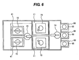
- FIG. 6 is a plan view showing a substrate processing apparatus provided with a plurality of substrate processing units including the first back-surface polishing unit 11 and the second back-surface polishing unit 41.
- FIG. 7 is a side view of the substrate processing apparatus shown in FIG. 6 .
- This substrate processing apparatus has load ports 66 on which wafer cassettes 65, each storing a plurality of wafers W, are placed, two first back-surface polishing units 11, two second back-surface polishing units 41, two cleaning units 72 each for cleaning the polished wafer W, and two drying units 73 each for drying the cleaned wafer W.
- the two cleaning units 72 are disposed on the two second back-surface polishing units 41, respectively.
- the two drying units 73 are disposed on the two first back-surface polishing units 11, respectively.
- a first transfer robot 74 is provided between the load ports 66 and the first back-surface polishing units 11. Further, a second transfer robot 75 is provided between the first back-surface polishing units 11 and the second back-surface polishing units 41.
- the wafer W in the wafer cassette 65 is transported to the first back-surface polishing unit 11 by the first transfer robot 74, and the outer circumferential region of the back surface of the wafer W is polished in the first back-surface polishing unit 11.
- the first polishing head 14 of the first back-surface polishing unit 11 may be provided with a tilting mechanism so that the first polishing head 14 can further polish the bevel portion of the wafer W.
- the wafer W is removed from the first back-surface polishing unit 11 by the second transfer robot 75, and is inverted such that the back surface of the wafer W faces upward.
- the inverted wafer W is then transported to the second back-surface polishing unit 41, where the center-side region of the back surface of the wafer W is polished.
- the wafer W Before being transported to the second back-surface polishing unit 41, the wafer W, whose outer circumferential region of the back surface has been polished, may be transported to the cleaning unit 72 so that the wafer W is cleaned.
- the wafer W whose back surface in its entirety has been polished, is removed from the second back-surface polishing unit 41 by the second transfer robot 75, and is inverted such that the back surface of the wafer W faces downward.
- the wafer W is transported to the cleaning unit 72.
- This cleaning unit 72 has an upper roll sponge and a lower roll sponge which are arranged so as to sandwich the wafer W therebetween.
- the cleaning unit 72 scrubs both surfaces of the wafer W with these roll sponges while supplying a cleaning liquid onto both surfaces of the wafer W.
- the cleaned wafer W is transported to the drying unit 73 by the second transfer robot 75.
- the drying unit 73 rotates the wafer W at a high speed around the axis of the wafer W to thereby spin-dry the wafer W.
- the dried wafer W is returned to the wafer cassette 65 on the load port 66 by the first transfer robot 74.
- the substrate processing apparatus performs a series of processes including polishing of the back surface of the wafer W, cleaning of the wafer W, and drying of the wafer W.
- the first back-surface polishing unit 11, the second back-surface polishing unit 41, the cleaning unit 72, and the drying unit 73 are constructed as modularized units, respectively, and an arrangement of these units can be changed freely.
- a notch polishing unit for polishing a notch portion of the wafer W may be provided instead of either or both of the two first back-surface polishing units 11 shown in FIG. 6 .
Landscapes
- Engineering & Computer Science (AREA)
- Mechanical Engineering (AREA)
- Chemical & Material Sciences (AREA)
- Ceramic Engineering (AREA)
- Inorganic Chemistry (AREA)
- Mechanical Treatment Of Semiconductor (AREA)
- Finish Polishing, Edge Sharpening, And Grinding By Specific Grinding Devices (AREA)
- Grinding And Polishing Of Tertiary Curved Surfaces And Surfaces With Complex Shapes (AREA)
Priority Applications (1)
| Application Number | Priority Date | Filing Date | Title |
|---|---|---|---|
| EP16181386.0A EP3112086A3 (en) | 2013-02-01 | 2014-01-29 | Method of polishing back surface of substrate and substrate processing apparatus |
Applications Claiming Priority (1)
| Application Number | Priority Date | Filing Date | Title |
|---|---|---|---|
| JP2013018476A JP6100002B2 (ja) | 2013-02-01 | 2013-02-01 | 基板裏面の研磨方法および基板処理装置 |
Related Child Applications (2)
| Application Number | Title | Priority Date | Filing Date |
|---|---|---|---|
| EP16181386.0A Division EP3112086A3 (en) | 2013-02-01 | 2014-01-29 | Method of polishing back surface of substrate and substrate processing apparatus |
| EP16181386.0A Division-Into EP3112086A3 (en) | 2013-02-01 | 2014-01-29 | Method of polishing back surface of substrate and substrate processing apparatus |
Publications (3)
| Publication Number | Publication Date |
|---|---|
| EP2762274A2 EP2762274A2 (en) | 2014-08-06 |
| EP2762274A3 EP2762274A3 (en) | 2015-06-03 |
| EP2762274B1 true EP2762274B1 (en) | 2016-09-21 |
Family
ID=50031138
Family Applications (2)
| Application Number | Title | Priority Date | Filing Date |
|---|---|---|---|
| EP14020010.6A Active EP2762274B1 (en) | 2013-02-01 | 2014-01-29 | Method of polishing back surface of substrate and substrate processing apparatus |
| EP16181386.0A Withdrawn EP3112086A3 (en) | 2013-02-01 | 2014-01-29 | Method of polishing back surface of substrate and substrate processing apparatus |
Family Applications After (1)
| Application Number | Title | Priority Date | Filing Date |
|---|---|---|---|
| EP16181386.0A Withdrawn EP3112086A3 (en) | 2013-02-01 | 2014-01-29 | Method of polishing back surface of substrate and substrate processing apparatus |
Country Status (6)
| Country | Link |
|---|---|
| US (1) | US9808903B2 (enExample) |
| EP (2) | EP2762274B1 (enExample) |
| JP (1) | JP6100002B2 (enExample) |
| KR (1) | KR102142893B1 (enExample) |
| CN (1) | CN103962941B (enExample) |
| TW (1) | TWI585838B (enExample) |
Families Citing this family (22)
| Publication number | Priority date | Publication date | Assignee | Title |
|---|---|---|---|---|
| JP6100002B2 (ja) | 2013-02-01 | 2017-03-22 | 株式会社荏原製作所 | 基板裏面の研磨方法および基板処理装置 |
| CN105150089B (zh) * | 2015-08-14 | 2019-06-28 | 深圳市中天超硬工具股份有限公司 | 金刚石盘表面研磨装置及研磨方法 |
| JP6560572B2 (ja) | 2015-09-14 | 2019-08-14 | 株式会社荏原製作所 | 反転機および基板研磨装置 |
| JP2017108113A (ja) * | 2015-11-27 | 2017-06-15 | 株式会社荏原製作所 | 基板処理装置および基板処理方法ならびに基板処理装置の制御プログラム |
| JP6577385B2 (ja) | 2016-02-12 | 2019-09-18 | 株式会社荏原製作所 | 基板保持モジュール、基板処理装置、および基板処理方法 |
| JP2017147334A (ja) * | 2016-02-17 | 2017-08-24 | 株式会社荏原製作所 | 基板の裏面を洗浄する装置および方法 |
| JP2017148931A (ja) * | 2016-02-19 | 2017-08-31 | 株式会社荏原製作所 | 研磨装置および研磨方法 |
| JP6625461B2 (ja) * | 2016-03-23 | 2019-12-25 | 株式会社荏原製作所 | 研磨装置 |
| JP6672207B2 (ja) * | 2016-07-14 | 2020-03-25 | 株式会社荏原製作所 | 基板の表面を研磨する装置および方法 |
| TWI821887B (zh) * | 2016-11-29 | 2023-11-11 | 日商東京威力科創股份有限公司 | 基板處理裝置、基板處理方法及記錄媒體 |
| JP6882017B2 (ja) | 2017-03-06 | 2021-06-02 | 株式会社荏原製作所 | 研磨方法、研磨装置、および基板処理システム |
| JP6920849B2 (ja) * | 2017-03-27 | 2021-08-18 | 株式会社荏原製作所 | 基板処理方法および装置 |
| EP3396707B1 (en) | 2017-04-28 | 2021-11-03 | Ebara Corporation | Apparatus and method for cleaning a back surface of a substrate |
| US10651057B2 (en) | 2017-05-01 | 2020-05-12 | Ebara Corporation | Apparatus and method for cleaning a back surface of a substrate |
| KR102135060B1 (ko) | 2017-05-10 | 2020-07-20 | 가부시키가이샤 에바라 세이사꾸쇼 | 기판의 이면을 세정하는 장치 및 방법 |
| JP6779173B2 (ja) | 2017-05-18 | 2020-11-04 | 株式会社荏原製作所 | 基板処理装置、プログラムを記録した記録媒体 |
| JP6974067B2 (ja) * | 2017-08-17 | 2021-12-01 | 株式会社荏原製作所 | 基板を研磨する方法および装置 |
| JP6908496B2 (ja) | 2017-10-25 | 2021-07-28 | 株式会社荏原製作所 | 研磨装置 |
| JP2019091746A (ja) * | 2017-11-13 | 2019-06-13 | 株式会社荏原製作所 | 基板の表面を処理する装置および方法 |
| JP7020986B2 (ja) | 2018-04-16 | 2022-02-16 | 株式会社荏原製作所 | 基板処理装置および基板保持装置 |
| KR20240154574A (ko) * | 2022-02-25 | 2024-10-25 | 가부시키가이샤 에바라 세이사꾸쇼 | 기판 연마 장치 |
| JP2024074050A (ja) * | 2022-11-18 | 2024-05-30 | 株式会社荏原製作所 | 基板処理装置 |
Family Cites Families (41)
| Publication number | Priority date | Publication date | Assignee | Title |
|---|---|---|---|---|
| JP3114156B2 (ja) * | 1994-06-28 | 2000-12-04 | 株式会社荏原製作所 | 洗浄方法および装置 |
| US6245677B1 (en) | 1999-07-28 | 2001-06-12 | Noor Haq | Backside chemical etching and polishing |
| JP2001110771A (ja) * | 1999-10-08 | 2001-04-20 | Ebara Corp | 基板洗浄装置及び基板処理装置 |
| DE10004578C1 (de) * | 2000-02-03 | 2001-07-26 | Wacker Siltronic Halbleitermat | Verfahren zur Herstellung einer Halbleiterscheibe mit polierter Kante |
| JP2001345298A (ja) | 2000-05-31 | 2001-12-14 | Ebara Corp | ポリッシング装置及び方法 |
| US6722964B2 (en) * | 2000-04-04 | 2004-04-20 | Ebara Corporation | Polishing apparatus and method |
| US6609950B2 (en) * | 2000-07-05 | 2003-08-26 | Ebara Corporation | Method for polishing a substrate |
| JP2002025952A (ja) * | 2000-07-07 | 2002-01-25 | Disco Abrasive Syst Ltd | 半導体ウエーハの処理方法 |
| DE10058305A1 (de) * | 2000-11-24 | 2002-06-06 | Wacker Siltronic Halbleitermat | Verfahren zur Oberflächenpolitur von Siliciumscheiben |
| JP2004515918A (ja) * | 2000-12-04 | 2004-05-27 | 株式会社荏原製作所 | 基板処理装置及びその方法 |
| JP4156200B2 (ja) * | 2001-01-09 | 2008-09-24 | 株式会社荏原製作所 | 研磨装置及び研磨方法 |
| KR100420205B1 (ko) * | 2001-09-10 | 2004-03-04 | 주식회사 하이닉스반도체 | 웨이퍼 제조 방법 |
| JP3949941B2 (ja) * | 2001-11-26 | 2007-07-25 | 株式会社東芝 | 半導体装置の製造方法および研磨装置 |
| JP4090247B2 (ja) * | 2002-02-12 | 2008-05-28 | 株式会社荏原製作所 | 基板処理装置 |
| JP4125148B2 (ja) * | 2003-02-03 | 2008-07-30 | 株式会社荏原製作所 | 基板処理装置 |
| US6913520B1 (en) * | 2004-01-16 | 2005-07-05 | United Microelectronics Corp. | All-in-one polishing process for a semiconductor wafer |
| CN100351040C (zh) * | 2004-03-25 | 2007-11-28 | 力晶半导体股份有限公司 | 晶片研磨机台 |
| JP2005305586A (ja) * | 2004-04-20 | 2005-11-04 | Nihon Micro Coating Co Ltd | 研磨装置 |
| JP4815801B2 (ja) * | 2004-12-28 | 2011-11-16 | 信越半導体株式会社 | シリコンウエーハの研磨方法および製造方法および円板状ワークの研磨装置ならびにシリコンウエーハ |
| JP2007258274A (ja) * | 2006-03-20 | 2007-10-04 | Ebara Corp | 基板処理方法、及び基板処理装置 |
| JP2008036783A (ja) * | 2006-08-08 | 2008-02-21 | Sony Corp | 研磨方法および研磨装置 |
| JP4913517B2 (ja) * | 2006-09-26 | 2012-04-11 | 株式会社ディスコ | ウエーハの研削加工方法 |
| JP2008042220A (ja) * | 2007-09-25 | 2008-02-21 | Ebara Corp | 基板処理方法及び装置 |
| JP5274993B2 (ja) * | 2007-12-03 | 2013-08-28 | 株式会社荏原製作所 | 研磨装置 |
| JP5478604B2 (ja) * | 2008-03-31 | 2014-04-23 | エムイーエムシー・エレクトロニック・マテリアルズ・インコーポレイテッド | シリコンウェハの端部をエッチングするための方法 |
| JP5160993B2 (ja) * | 2008-07-25 | 2013-03-13 | 株式会社荏原製作所 | 基板処理装置 |
| DE102008045534B4 (de) * | 2008-09-03 | 2011-12-01 | Siltronic Ag | Verfahren zum Polieren einer Halbleiterscheibe |
| DE102008053610B4 (de) * | 2008-10-29 | 2011-03-31 | Siltronic Ag | Verfahren zum beidseitigen Polieren einer Halbleiterscheibe |
| KR101004435B1 (ko) | 2008-11-28 | 2010-12-28 | 세메스 주식회사 | 기판 연마 장치 및 이를 이용한 기판 연마 방법 |
| DE102009030295B4 (de) * | 2009-06-24 | 2014-05-08 | Siltronic Ag | Verfahren zur Herstellung einer Halbleiterscheibe |
| JP5519256B2 (ja) * | 2009-12-03 | 2014-06-11 | 株式会社荏原製作所 | 裏面が研削された基板を研磨する方法および装置 |
| JP5663295B2 (ja) * | 2010-01-15 | 2015-02-04 | 株式会社荏原製作所 | 研磨装置、研磨方法、研磨具を押圧する押圧部材 |
| JP2011224680A (ja) * | 2010-04-16 | 2011-11-10 | Ebara Corp | 研磨方法及び研磨装置 |
| JP5460537B2 (ja) * | 2010-06-17 | 2014-04-02 | 東京エレクトロン株式会社 | 基板裏面研磨装置、基板裏面研磨システム及び基板裏面研磨方法並びに基板裏面研磨プログラムを記録した記録媒体 |
| JP5649417B2 (ja) * | 2010-11-26 | 2015-01-07 | 株式会社荏原製作所 | 固定砥粒を有する研磨テープを用いた基板の研磨方法 |
| US9457447B2 (en) * | 2011-03-28 | 2016-10-04 | Ebara Corporation | Polishing apparatus and polishing method |
| JP5946260B2 (ja) * | 2011-11-08 | 2016-07-06 | 株式会社ディスコ | ウエーハの加工方法 |
| JP6113960B2 (ja) | 2012-02-21 | 2017-04-12 | 株式会社荏原製作所 | 基板処理装置および基板処理方法 |
| JP6140439B2 (ja) * | 2012-12-27 | 2017-05-31 | 株式会社荏原製作所 | 研磨装置、及び研磨方法 |
| JP6100002B2 (ja) | 2013-02-01 | 2017-03-22 | 株式会社荏原製作所 | 基板裏面の研磨方法および基板処理装置 |
| US9287127B2 (en) * | 2014-02-17 | 2016-03-15 | Taiwan Semiconductor Manufacturing Co., Ltd. | Wafer back-side polishing system and method for integrated circuit device manufacturing processes |
-
2013
- 2013-02-01 JP JP2013018476A patent/JP6100002B2/ja active Active
-
2014
- 2014-01-23 KR KR1020140008156A patent/KR102142893B1/ko active Active
- 2014-01-27 CN CN201410039682.7A patent/CN103962941B/zh active Active
- 2014-01-28 TW TW103103084A patent/TWI585838B/zh active
- 2014-01-29 EP EP14020010.6A patent/EP2762274B1/en active Active
- 2014-01-29 EP EP16181386.0A patent/EP3112086A3/en not_active Withdrawn
- 2014-01-29 US US14/167,934 patent/US9808903B2/en active Active
Also Published As
| Publication number | Publication date |
|---|---|
| EP3112086A2 (en) | 2017-01-04 |
| TWI585838B (zh) | 2017-06-01 |
| TW201436016A (zh) | 2014-09-16 |
| EP2762274A2 (en) | 2014-08-06 |
| EP2762274A3 (en) | 2015-06-03 |
| US20140220866A1 (en) | 2014-08-07 |
| KR20140099191A (ko) | 2014-08-11 |
| JP6100002B2 (ja) | 2017-03-22 |
| KR102142893B1 (ko) | 2020-08-10 |
| EP3112086A3 (en) | 2017-01-18 |
| JP2014150178A (ja) | 2014-08-21 |
| US9808903B2 (en) | 2017-11-07 |
| CN103962941A (zh) | 2014-08-06 |
| CN103962941B (zh) | 2018-07-20 |
Similar Documents
| Publication | Publication Date | Title |
|---|---|---|
| EP2762274B1 (en) | Method of polishing back surface of substrate and substrate processing apparatus | |
| US10799917B2 (en) | Substrate processing apparatus and substrate processing method | |
| US6558239B2 (en) | Polishing apparatus | |
| US9711381B2 (en) | Methods and apparatus for post-chemical mechanical planarization substrate cleaning | |
| US20090038642A1 (en) | Methods and apparatus for cleaning an edge of a substrate | |
| US10651057B2 (en) | Apparatus and method for cleaning a back surface of a substrate | |
| US20140261539A1 (en) | Disk/pad clean with wafer and wafer edge/bevel clean module for chemical mechanical polishing | |
| JP4660494B2 (ja) | 研磨カートリッジ | |
| JP7148349B2 (ja) | 基板処理装置および基板処理方法 | |
| US10376929B2 (en) | Apparatus and method for polishing a surface of a substrate | |
| JP2017147334A (ja) | 基板の裏面を洗浄する装置および方法 | |
| JP6625461B2 (ja) | 研磨装置 | |
| JPWO2019138881A1 (ja) | 洗浄装置、洗浄方法及びコンピュータ記憶媒体 | |
| JP2018160509A (ja) | 基板処理装置および基板処理方法 | |
| EP3396707B1 (en) | Apparatus and method for cleaning a back surface of a substrate | |
| KR102135060B1 (ko) | 기판의 이면을 세정하는 장치 및 방법 | |
| TWI706813B (zh) | 基板處理裝置 | |
| WO2023162714A1 (ja) | 基板研磨装置 | |
| JP2023124820A (ja) | 基板研磨装置 |
Legal Events
| Date | Code | Title | Description |
|---|---|---|---|
| PUAI | Public reference made under article 153(3) epc to a published international application that has entered the european phase |
Free format text: ORIGINAL CODE: 0009012 |
|
| 17P | Request for examination filed |
Effective date: 20140129 |
|
| AK | Designated contracting states |
Kind code of ref document: A2 Designated state(s): AL AT BE BG CH CY CZ DE DK EE ES FI FR GB GR HR HU IE IS IT LI LT LU LV MC MK MT NL NO PL PT RO RS SE SI SK SM TR |
|
| AX | Request for extension of the european patent |
Extension state: BA ME |
|
| PUAL | Search report despatched |
Free format text: ORIGINAL CODE: 0009013 |
|
| AK | Designated contracting states |
Kind code of ref document: A3 Designated state(s): AL AT BE BG CH CY CZ DE DK EE ES FI FR GB GR HR HU IE IS IT LI LT LU LV MC MK MT NL NO PL PT RO RS SE SI SK SM TR |
|
| AX | Request for extension of the european patent |
Extension state: BA ME |
|
| RIC1 | Information provided on ipc code assigned before grant |
Ipc: B24B 37/04 20120101AFI20150429BHEP Ipc: B24B 7/22 20060101ALI20150429BHEP Ipc: B24B 21/00 20060101ALI20150429BHEP Ipc: B24B 37/30 20120101ALI20150429BHEP |
|
| R17P | Request for examination filed (corrected) |
Effective date: 20151202 |
|
| RBV | Designated contracting states (corrected) |
Designated state(s): AL AT BE BG CH CY CZ DE DK EE ES FI FR GB GR HR HU IE IS IT LI LT LU LV MC MK MT NL NO PL PT RO RS SE SI SK SM TR |
|
| GRAP | Despatch of communication of intention to grant a patent |
Free format text: ORIGINAL CODE: EPIDOSNIGR1 |
|
| INTG | Intention to grant announced |
Effective date: 20160418 |
|
| GRAS | Grant fee paid |
Free format text: ORIGINAL CODE: EPIDOSNIGR3 |
|
| GRAA | (expected) grant |
Free format text: ORIGINAL CODE: 0009210 |
|
| AK | Designated contracting states |
Kind code of ref document: B1 Designated state(s): AL AT BE BG CH CY CZ DE DK EE ES FI FR GB GR HR HU IE IS IT LI LT LU LV MC MK MT NL NO PL PT RO RS SE SI SK SM TR |
|
| REG | Reference to a national code |
Ref country code: GB Ref legal event code: FG4D |
|
| REG | Reference to a national code |
Ref country code: CH Ref legal event code: EP |
|
| REG | Reference to a national code |
Ref country code: AT Ref legal event code: REF Ref document number: 830653 Country of ref document: AT Kind code of ref document: T Effective date: 20161015 |
|
| REG | Reference to a national code |
Ref country code: IE Ref legal event code: FG4D |
|
| REG | Reference to a national code |
Ref country code: DE Ref legal event code: R096 Ref document number: 602014003692 Country of ref document: DE |
|
| REG | Reference to a national code |
Ref country code: LT Ref legal event code: MG4D Ref country code: NL Ref legal event code: MP Effective date: 20160921 |
|
| PG25 | Lapsed in a contracting state [announced via postgrant information from national office to epo] |
Ref country code: RS Free format text: LAPSE BECAUSE OF FAILURE TO SUBMIT A TRANSLATION OF THE DESCRIPTION OR TO PAY THE FEE WITHIN THE PRESCRIBED TIME-LIMIT Effective date: 20160921 Ref country code: LT Free format text: LAPSE BECAUSE OF FAILURE TO SUBMIT A TRANSLATION OF THE DESCRIPTION OR TO PAY THE FEE WITHIN THE PRESCRIBED TIME-LIMIT Effective date: 20160921 Ref country code: NO Free format text: LAPSE BECAUSE OF FAILURE TO SUBMIT A TRANSLATION OF THE DESCRIPTION OR TO PAY THE FEE WITHIN THE PRESCRIBED TIME-LIMIT Effective date: 20161221 Ref country code: FI Free format text: LAPSE BECAUSE OF FAILURE TO SUBMIT A TRANSLATION OF THE DESCRIPTION OR TO PAY THE FEE WITHIN THE PRESCRIBED TIME-LIMIT Effective date: 20160921 |
|
| REG | Reference to a national code |
Ref country code: AT Ref legal event code: MK05 Ref document number: 830653 Country of ref document: AT Kind code of ref document: T Effective date: 20160921 |
|
| PG25 | Lapsed in a contracting state [announced via postgrant information from national office to epo] |
Ref country code: LV Free format text: LAPSE BECAUSE OF FAILURE TO SUBMIT A TRANSLATION OF THE DESCRIPTION OR TO PAY THE FEE WITHIN THE PRESCRIBED TIME-LIMIT Effective date: 20160921 Ref country code: GR Free format text: LAPSE BECAUSE OF FAILURE TO SUBMIT A TRANSLATION OF THE DESCRIPTION OR TO PAY THE FEE WITHIN THE PRESCRIBED TIME-LIMIT Effective date: 20161222 Ref country code: SE Free format text: LAPSE BECAUSE OF FAILURE TO SUBMIT A TRANSLATION OF THE DESCRIPTION OR TO PAY THE FEE WITHIN THE PRESCRIBED TIME-LIMIT Effective date: 20160921 Ref country code: NL Free format text: LAPSE BECAUSE OF FAILURE TO SUBMIT A TRANSLATION OF THE DESCRIPTION OR TO PAY THE FEE WITHIN THE PRESCRIBED TIME-LIMIT Effective date: 20160921 |
|
| PG25 | Lapsed in a contracting state [announced via postgrant information from national office to epo] |
Ref country code: RO Free format text: LAPSE BECAUSE OF FAILURE TO SUBMIT A TRANSLATION OF THE DESCRIPTION OR TO PAY THE FEE WITHIN THE PRESCRIBED TIME-LIMIT Effective date: 20160921 Ref country code: EE Free format text: LAPSE BECAUSE OF FAILURE TO SUBMIT A TRANSLATION OF THE DESCRIPTION OR TO PAY THE FEE WITHIN THE PRESCRIBED TIME-LIMIT Effective date: 20160921 |
|
| PG25 | Lapsed in a contracting state [announced via postgrant information from national office to epo] |
Ref country code: PT Free format text: LAPSE BECAUSE OF FAILURE TO SUBMIT A TRANSLATION OF THE DESCRIPTION OR TO PAY THE FEE WITHIN THE PRESCRIBED TIME-LIMIT Effective date: 20170123 Ref country code: SM Free format text: LAPSE BECAUSE OF FAILURE TO SUBMIT A TRANSLATION OF THE DESCRIPTION OR TO PAY THE FEE WITHIN THE PRESCRIBED TIME-LIMIT Effective date: 20160921 Ref country code: IS Free format text: LAPSE BECAUSE OF FAILURE TO SUBMIT A TRANSLATION OF THE DESCRIPTION OR TO PAY THE FEE WITHIN THE PRESCRIBED TIME-LIMIT Effective date: 20170121 Ref country code: PL Free format text: LAPSE BECAUSE OF FAILURE TO SUBMIT A TRANSLATION OF THE DESCRIPTION OR TO PAY THE FEE WITHIN THE PRESCRIBED TIME-LIMIT Effective date: 20160921 Ref country code: SK Free format text: LAPSE BECAUSE OF FAILURE TO SUBMIT A TRANSLATION OF THE DESCRIPTION OR TO PAY THE FEE WITHIN THE PRESCRIBED TIME-LIMIT Effective date: 20160921 Ref country code: AT Free format text: LAPSE BECAUSE OF FAILURE TO SUBMIT A TRANSLATION OF THE DESCRIPTION OR TO PAY THE FEE WITHIN THE PRESCRIBED TIME-LIMIT Effective date: 20160921 Ref country code: ES Free format text: LAPSE BECAUSE OF FAILURE TO SUBMIT A TRANSLATION OF THE DESCRIPTION OR TO PAY THE FEE WITHIN THE PRESCRIBED TIME-LIMIT Effective date: 20160921 Ref country code: BE Free format text: LAPSE BECAUSE OF FAILURE TO SUBMIT A TRANSLATION OF THE DESCRIPTION OR TO PAY THE FEE WITHIN THE PRESCRIBED TIME-LIMIT Effective date: 20160921 Ref country code: CZ Free format text: LAPSE BECAUSE OF FAILURE TO SUBMIT A TRANSLATION OF THE DESCRIPTION OR TO PAY THE FEE WITHIN THE PRESCRIBED TIME-LIMIT Effective date: 20160921 Ref country code: BG Free format text: LAPSE BECAUSE OF FAILURE TO SUBMIT A TRANSLATION OF THE DESCRIPTION OR TO PAY THE FEE WITHIN THE PRESCRIBED TIME-LIMIT Effective date: 20161221 |
|
| REG | Reference to a national code |
Ref country code: DE Ref legal event code: R097 Ref document number: 602014003692 Country of ref document: DE |
|
| PG25 | Lapsed in a contracting state [announced via postgrant information from national office to epo] |
Ref country code: IT Free format text: LAPSE BECAUSE OF FAILURE TO SUBMIT A TRANSLATION OF THE DESCRIPTION OR TO PAY THE FEE WITHIN THE PRESCRIBED TIME-LIMIT Effective date: 20160921 |
|
| PLBE | No opposition filed within time limit |
Free format text: ORIGINAL CODE: 0009261 |
|
| STAA | Information on the status of an ep patent application or granted ep patent |
Free format text: STATUS: NO OPPOSITION FILED WITHIN TIME LIMIT |
|
| PG25 | Lapsed in a contracting state [announced via postgrant information from national office to epo] |
Ref country code: DK Free format text: LAPSE BECAUSE OF FAILURE TO SUBMIT A TRANSLATION OF THE DESCRIPTION OR TO PAY THE FEE WITHIN THE PRESCRIBED TIME-LIMIT Effective date: 20160921 |
|
| 26N | No opposition filed |
Effective date: 20170622 |
|
| REG | Reference to a national code |
Ref country code: CH Ref legal event code: PL |
|
| PG25 | Lapsed in a contracting state [announced via postgrant information from national office to epo] |
Ref country code: MC Free format text: LAPSE BECAUSE OF FAILURE TO SUBMIT A TRANSLATION OF THE DESCRIPTION OR TO PAY THE FEE WITHIN THE PRESCRIBED TIME-LIMIT Effective date: 20160921 |
|
| REG | Reference to a national code |
Ref country code: FR Ref legal event code: ST Effective date: 20170929 |
|
| PG25 | Lapsed in a contracting state [announced via postgrant information from national office to epo] |
Ref country code: LI Free format text: LAPSE BECAUSE OF NON-PAYMENT OF DUE FEES Effective date: 20170131 Ref country code: FR Free format text: LAPSE BECAUSE OF NON-PAYMENT OF DUE FEES Effective date: 20170131 Ref country code: CH Free format text: LAPSE BECAUSE OF NON-PAYMENT OF DUE FEES Effective date: 20170131 |
|
| REG | Reference to a national code |
Ref country code: IE Ref legal event code: MM4A |
|
| PG25 | Lapsed in a contracting state [announced via postgrant information from national office to epo] |
Ref country code: SI Free format text: LAPSE BECAUSE OF FAILURE TO SUBMIT A TRANSLATION OF THE DESCRIPTION OR TO PAY THE FEE WITHIN THE PRESCRIBED TIME-LIMIT Effective date: 20160921 Ref country code: LU Free format text: LAPSE BECAUSE OF NON-PAYMENT OF DUE FEES Effective date: 20170129 |
|
| PG25 | Lapsed in a contracting state [announced via postgrant information from national office to epo] |
Ref country code: IE Free format text: LAPSE BECAUSE OF NON-PAYMENT OF DUE FEES Effective date: 20170129 |
|
| GBPC | Gb: european patent ceased through non-payment of renewal fee |
Effective date: 20180129 |
|
| PG25 | Lapsed in a contracting state [announced via postgrant information from national office to epo] |
Ref country code: MT Free format text: LAPSE BECAUSE OF NON-PAYMENT OF DUE FEES Effective date: 20170129 |
|
| PG25 | Lapsed in a contracting state [announced via postgrant information from national office to epo] |
Ref country code: AL Free format text: LAPSE BECAUSE OF FAILURE TO SUBMIT A TRANSLATION OF THE DESCRIPTION OR TO PAY THE FEE WITHIN THE PRESCRIBED TIME-LIMIT Effective date: 20160921 |
|
| PG25 | Lapsed in a contracting state [announced via postgrant information from national office to epo] |
Ref country code: GB Free format text: LAPSE BECAUSE OF NON-PAYMENT OF DUE FEES Effective date: 20180129 |
|
| PG25 | Lapsed in a contracting state [announced via postgrant information from national office to epo] |
Ref country code: HU Free format text: LAPSE BECAUSE OF FAILURE TO SUBMIT A TRANSLATION OF THE DESCRIPTION OR TO PAY THE FEE WITHIN THE PRESCRIBED TIME-LIMIT; INVALID AB INITIO Effective date: 20140129 |
|
| PG25 | Lapsed in a contracting state [announced via postgrant information from national office to epo] |
Ref country code: CY Free format text: LAPSE BECAUSE OF NON-PAYMENT OF DUE FEES Effective date: 20160921 |
|
| PG25 | Lapsed in a contracting state [announced via postgrant information from national office to epo] |
Ref country code: MK Free format text: LAPSE BECAUSE OF FAILURE TO SUBMIT A TRANSLATION OF THE DESCRIPTION OR TO PAY THE FEE WITHIN THE PRESCRIBED TIME-LIMIT Effective date: 20160921 |
|
| PG25 | Lapsed in a contracting state [announced via postgrant information from national office to epo] |
Ref country code: TR Free format text: LAPSE BECAUSE OF FAILURE TO SUBMIT A TRANSLATION OF THE DESCRIPTION OR TO PAY THE FEE WITHIN THE PRESCRIBED TIME-LIMIT Effective date: 20160921 |
|
| PG25 | Lapsed in a contracting state [announced via postgrant information from national office to epo] |
Ref country code: HR Free format text: LAPSE BECAUSE OF FAILURE TO SUBMIT A TRANSLATION OF THE DESCRIPTION OR TO PAY THE FEE WITHIN THE PRESCRIBED TIME-LIMIT Effective date: 20160921 |
|
| P01 | Opt-out of the competence of the unified patent court (upc) registered |
Effective date: 20230428 |
|
| PGFP | Annual fee paid to national office [announced via postgrant information from national office to epo] |
Ref country code: DE Payment date: 20241203 Year of fee payment: 12 |