EP2762060B1 - Optical coherence tomographic imaging apparatus and method for controlling the same - Google Patents
Optical coherence tomographic imaging apparatus and method for controlling the same Download PDFInfo
- Publication number
- EP2762060B1 EP2762060B1 EP14000250.2A EP14000250A EP2762060B1 EP 2762060 B1 EP2762060 B1 EP 2762060B1 EP 14000250 A EP14000250 A EP 14000250A EP 2762060 B1 EP2762060 B1 EP 2762060B1
- Authority
- EP
- European Patent Office
- Prior art keywords
- subject
- scanning
- eye
- scan
- fundus
- Prior art date
- Legal status (The legal status is an assumption and is not a legal conclusion. Google has not performed a legal analysis and makes no representation as to the accuracy of the status listed.)
- Active
Links
Images


Classifications
-
- A—HUMAN NECESSITIES
- A61—MEDICAL OR VETERINARY SCIENCE; HYGIENE
- A61B—DIAGNOSIS; SURGERY; IDENTIFICATION
- A61B3/00—Apparatus for testing the eyes; Instruments for examining the eyes
- A61B3/10—Objective types, i.e. instruments for examining the eyes independent of the patients' perceptions or reactions
- A61B3/102—Objective types, i.e. instruments for examining the eyes independent of the patients' perceptions or reactions for optical coherence tomography [OCT]
-
- A—HUMAN NECESSITIES
- A61—MEDICAL OR VETERINARY SCIENCE; HYGIENE
- A61B—DIAGNOSIS; SURGERY; IDENTIFICATION
- A61B3/00—Apparatus for testing the eyes; Instruments for examining the eyes
- A61B3/0016—Operational features thereof
- A61B3/0025—Operational features thereof characterised by electronic signal processing, e.g. eye models
-
- A—HUMAN NECESSITIES
- A61—MEDICAL OR VETERINARY SCIENCE; HYGIENE
- A61B—DIAGNOSIS; SURGERY; IDENTIFICATION
- A61B3/00—Apparatus for testing the eyes; Instruments for examining the eyes
- A61B3/10—Objective types, i.e. instruments for examining the eyes independent of the patients' perceptions or reactions
- A61B3/113—Objective types, i.e. instruments for examining the eyes independent of the patients' perceptions or reactions for determining or recording eye movement
-
- A—HUMAN NECESSITIES
- A61—MEDICAL OR VETERINARY SCIENCE; HYGIENE
- A61B—DIAGNOSIS; SURGERY; IDENTIFICATION
- A61B3/00—Apparatus for testing the eyes; Instruments for examining the eyes
- A61B3/10—Objective types, i.e. instruments for examining the eyes independent of the patients' perceptions or reactions
- A61B3/12—Objective types, i.e. instruments for examining the eyes independent of the patients' perceptions or reactions for looking at the eye fundus, e.g. ophthalmoscopes
- A61B3/1225—Objective types, i.e. instruments for examining the eyes independent of the patients' perceptions or reactions for looking at the eye fundus, e.g. ophthalmoscopes using coherent radiation
-
- A—HUMAN NECESSITIES
- A61—MEDICAL OR VETERINARY SCIENCE; HYGIENE
- A61B—DIAGNOSIS; SURGERY; IDENTIFICATION
- A61B3/00—Apparatus for testing the eyes; Instruments for examining the eyes
- A61B3/10—Objective types, i.e. instruments for examining the eyes independent of the patients' perceptions or reactions
- A61B3/14—Arrangements specially adapted for eye photography
- A61B3/15—Arrangements specially adapted for eye photography with means for aligning, spacing or blocking spurious reflection ; with means for relaxing
- A61B3/152—Arrangements specially adapted for eye photography with means for aligning, spacing or blocking spurious reflection ; with means for relaxing for aligning
Definitions
- the present invention relates to an optical coherence tomographic imaging apparatus for capturing a tomographic image of a subject's eye through optical coherence, and a method for controlling the optical coherence tomographic imaging apparatus.
- a presently known optical coherence tomographic imaging apparatus based on optical coherence tomography utilizes multi-wavelength light wave interference.
- OCT optical coherence tomography
- the optical coherence tomographic imaging apparatus is used to acquire internal organ information with an endoscope and retina information in an ophthalmologic apparatus, and applied to increasing number of fields in the human body.
- An optical coherence tomographic imaging apparatus applied to the human eye is becoming essential for specialized retina clinic, as an ophthalmologic apparatus.
- Such an optical coherence tomographic imaging apparatus is capable of irradiating a sample with measuring light which is low-coherent light, and measuring backward scattering light from the sample by using an interferometer.
- image information in a depth direction at the one point on the sample can be acquired.
- a tomographic image of the sample can be acquired.
- the optical coherence tomographic imaging apparatus is applied to the fundus, the fundus of the subject's eye is scanned with the measuring light to capture a high-resolution tomographic image of the fundus of the subject's eye. Therefore, the optical coherence tomographic imaging apparatus is widely used in ophthalmology diagnosis of the retina.
- the optical coherence tomographic imaging apparatus uses a method for capturing a plurality of tomographic images by repetitively scanning a measurement target (fundus), in a horizontal or vertical direction.
- the optical coherence tomographic imaging apparatus scans an identical region on the fundus a plurality of times to capture a plurality of tomographic images of the identical region, and performs averaging processing on the captured tomographic images to acquire a high-definition tomographic image of the fundus.
- a three-dimensional image of the fundus can be acquired. In a case scanning the fundus a plurality of times in this way, however, since it takes a certain amount of time to complete image capturing, the eye may move during image capturing.
- Japanese Patent Application Laid-Open No. 2008-29467 discusses an ophthalmologic imaging apparatus having a tracking function. Specifically, the ophthalmologic imaging apparatus successively captures a plurality of front images of the subject's eye, detects the subject's eye movement by using the plurality of acquired front images, and corrects scanning positions according to the subject's eye movement.
- US 2012/0274783 A1 discloses an OCT system, comprising a computer to receive images of a sample from a video camera, wherein the computer processes the images and provides a motion offset signal based on the images to a two-dimensional transverse scanner.
- US 2005/0140984 A1 discloses an OCT system with a polarizing splitter disposed to direct light in an interferometer such that the OCT detector operates in a noise-optimized regime. When scanning an eye, the system detector simultaneously produces a low-frequency component representing a scanning laser ophthalmoscope-like (SLO-like) image pixel and a high frequency component representing a two-dimensional (2D) OCT en face image pixel of each point.
- SLO-like scanning laser ophthalmoscope-like
- the OCT image pixels may be remapped on the fly according to SLO-like image pixel remapping to create an undistorted 3D image data set for the scanned region.
- US 2011/0267581 A1 discloses an ophthalmologic apparatus that acquires a second fundus image of an eye to be inspected during a period different from a period during which a first fundus image is acquired; and calculates at least a rotation of movements of the eye to be inspected based on a plurality of characteristic images and the second fundus image.
- JP 2011-092291 discloses an ophthalmic observation apparatus which detects a blink of an eye while carrying out an OCT measurement.
- the present invention in its first aspect provides an optical coherence tomographic imaging apparatus as specified in claims 1 to 8, and further provides a method as defined in claims 9 to 14 and a program as defined in claim 15.
- One of objectives of the present exemplary embodiment is to acquire a tomographic image with reduced distortion due to this movement even if there arises a comparatively large subject's eye movement per unit time during tracking of the subject's eye movement.
- the optical coherence tomographic imaging apparatus can acquire the amount of subject's eye movement (for example, the amount of subject's eye rotation) based on a plurality of images of the subject's eye (for example, a plurality of fundus images) acquired at different times.
- the optical coherence tomographic imaging apparatus can determine whether the amount of subject's eye movement before a scan by a scanning unit exceeds a threshold value. In a case the amount of subject's eye movement before the scan is equal to or smaller than the threshold value, the optical coherence tomographic imaging apparatus according to the present exemplary embodiment can control the scanning unit to perform scanning position correction between the scan and the next scan based on the amount of subject's eye movement.
- An optical coherence tomographic imaging apparatus can control the scanning unit, in a case where the amount of subject's eye movement before the scan exceeds a threshold value, to restart scan of the scanning unit from a scanning position before the scan.
- An optical coherence tomographic imaging apparatus can detect a blink of the subject's eye before a scan by the scanning unit, based on a plurality of images of the subject's eye acquired at different times.
- An optical coherence tomographic imaging apparatus can control the scanning unit, in a case where a blink of the subject's eye is detected, to restart scan of the scanning unit from a scanning position before the scan.
- An optical coherence tomographic imaging apparatus can control the scanning unit (control the operation of a unit for tracking the subject's eye) to perform scanning position correction between a scan and the next scan of the scanning unit based on a plurality of images of the subject's eye acquired at different times.
- a distortion may arise in a tomographic image due to correction of a scanning position through fundus tracking.
- the interval of scanning position correction through fundus tracking is shorter than the time for acquiring information in the depth direction (A scan acquisition time) at one point on the subject's eye, no distortion arises in the tomographic image because the scanning position correction is suitably performed at each scanning point for acquiring one tomographic image.
- fundus tracking since a front fundus image is often used, it is difficult to make the interval of scanning position correction through fundus tracking shorter than a front image acquisition interval.
- the front image acquisition interval is about several tens of milliseconds which are longer than the A scan acquisition interval (generally, several tens of microseconds). Therefore, it is difficult to perform scanning position correction through fundus tracking for each point during scan on the subject's eye. Scanning position correction is performed at regular intervals for each amount of scanning range. After scanning position correction is performed at regular intervals, eye movements detected at regular intervals will be corrected at one time. As a result, in a case where scan is performed on the subject's eye, a rapid change in the scanning position will be produced at regular intervals. Such a rapid change in the scanning position appears as a tomographic deviation (distortion) at regular intervals on a captured tomographic image.
- Such a tomographic image distortion not only disturbs image diagnosis by a doctor but also causes misrecognition of the tomographic image distortion as a lesioned portion, possibly leading to misdiagnosis. Further, a tomographic image distortion may also have an adverse effect on an automatic retina layer boundary recognition function provided in many optical coherence tomographic imaging apparatuses. If a retina layer boundary is misrecognized, measurement values of the retina layer thickness based on the misrecognition will be displayed, possibly leading to misdiagnosis.
- This enables acquiring tomographic images with reduced distortion due to the subject's eye movement.
- the optical coherence tomographic imaging apparatus acquires a tomographic image of the subject's eye based on an interference light produced by the interference between return light from the subject's eye, irradiated with measuring light via a scanning unit, and reference light corresponding to the measuring light.
- the optical coherence tomographic imaging apparatus includes an optical head unit 100, a spectroscope 200, and a control unit 300. The following describes the configurations of the optical head unit 100, the spectroscope 200, and the control unit 300 in this order.
- the optical head unit 100 includes a measuring light optical system for capturing a two-dimensional image and a tomographic image of an anterior ocular segment Ea and a fundus Er of a subject's eye E.
- An objective lens 101-1 is disposed to face the subject's eye E.
- the optical path is branched by a first dichroic mirror 102 and a second dichroic mirror 103 disposed on the optical axis to function as an optical path separation unit. Specifically, the optical path is branched for each wavelength band into a measurement path L1 of an OCT optical system, a fundus observation optical path and a fixation lamp optical path L2, and an anterior ocular segment observation optical path L3.
- the optical path L2 is further branched for each wavelength band by a third dichroic mirror 118 into an optical path to an avalanche photodiode (APD) 115 for fundus observation, and an optical path to a fixation lamp 116.
- Lenses 101-2, 111, and 112 are disposed on the optical path L2.
- the lens 111 is driven by a motor (not illustrated) for focusing adjustment for the fixation lamp and fundus observation.
- the APD 115 has sensitivity in the vicinity of the wavelength of illumination light for fundus observation (not illustrated), specifically, 780 nanometers.
- the fixation lamp 116 generates visible light to prompt the subject to perform the fixation.
- An X scanner 117-1 (for the main scanning direction) and a Y scanner 117-2 (for the sub scanning direction intersecting with the main scanning direction) for scanning the fundus Er of the subject's eye E with light emitted from an illumination light source for fundus observation (not illustrated) are disposed on the optical path L2.
- the lens 101-2 is disposed so that its focal position comes to the vicinity of the center position between the X scanner 117-1 and the Y scanner 117-2.
- the X scanner 117-1 is a resonance type mirror, it may be a polygon mirror.
- the vicinity of the center position between the X scanner 117-1 and the Y scanner 117-2 has an optically conjugate relation with the pupillary position of the subject's eye E.
- the APD 115 (single detector) detects light dispersed and reflected by the fundus Er, as return light.
- the third dichroic mirror 118 which is a prism composed of a perforated mirror or a vapor-deposited hollow mirror, separates incident light into the illumination light and the return light from the fundus Er.
- a lens 141 and an infrared charge-coupled device (CCD) 142 for anterior ocular segment observation are disposed on the optical path L3.
- the infrared CCD 142 has sensitivity in the vicinity of the wavelength of illumination light for anterior ocular segment observation (not illustrated), specifically, 970 nanometers.
- the optical path L1 forms the OCT optical system, as described above, and is used to capture a tomographic image of the fundus Er of the subject's eye E. More specifically, the optical path L1 is used to acquire an interference signal for forming a tomographic image.
- a lens 101-3, a mirror 121, and an X scanner 122-1 and a Y scanner 122-2 as a scanning unit are disposed on the optical path L1 to deflect light on the fundus Er of the subject's eye E. Further, the X scanner 122-1 and the Y scanner 122-2 are disposed so that the center position between the X scanner 122-1 and the Y scanner 122-2 comes to the focal position of the lens 101-3. Further, the vicinity of the center position between the X scanner 122-1 and the Y scanner 122-2 has an optically conjugate relation with the pupillary position of the subject's eye E. With this configuration, the optical paths having the scanning unit as an object point become approximately parallel between the lenses 101-1 and 101-3. This enables providing an identical incident angle for the first dichroic mirror 102 and the second dichroic mirror 103 even when the X scanner 122-1 and the Y scanner 122-2 perform scanning.
- a measuring light source 130 serves as a light source for emitting the measuring light into the measurement path.
- the measuring light source 130 is a fiber end, and has an optically conjugate relation with the fundus Er of the subject's eye E.
- Lenses 123 and 124 are disposed on the optical path L1.
- the lens 123 is driven by a motor (not illustrated) to perform focusing adjustment. Focusing adjustment is performed so that the light emitted from the measuring light source 130 (fiber end) is focused on the fundus Er.
- the lens 123 which functions as a focusing adjustment unit is disposed between the measuring light source 130 and the X scanner 122-1 and the Y scanner 122-2 as a scanning unit. This makes it unnecessary to move the larger lens 101-3 and an optical fiber 125-2.
- This focusing adjustment enables forming of an image of the measuring light source 130 on the fundus Er of the subject's eye E, and the return light can be efficiently returned from the fundus Er of the subject's eye E to the optical fiber 125-2 via the measuring light source 130.
- the optical head unit 100 further includes a head driving unit 140.
- the head driving unit 140 includes three motors (not illustrated) to enable moving of the optical head unit 100 in the three-dimensional (X, Y, Z) directions with respect to the subject's eye E.
- the optical head unit 100 can be aligned with respect to the subject's eye E.
- the following describes the configurations of the optical path from the measuring light source 130, a reference light optical system, and the spectroscope 200.
- the measuring light source 130, an optical coupler 125, optical fibers 125-1 to 125-4, a lens 151, a dispersion compensation glass 152, a mirror 153, and a spectroscope 200 form a Michelson interference system.
- the optical fibers 125-1 to 125-4 (single mode optical fibers) are connected to and integrated with the optical coupler 125.
- the light emitted from the measuring light source 130 advances through the optical fiber 125-1, and is divided into measuring light on the side of the optical fiber 125-2 and reference light on the side of the optical fiber 125-3 by the optical coupler 125.
- the measuring light advances through the above-described optical path of the OCT optical system.
- the fundus Er of the subject's eye E observation target
- the measuring light reaches the optical coupler 125 via the same optical path.
- the reference light advances through the optical fiber 125-3, the lens 151, the dispersion compensation glass 152 provided to join dispersion of the measuring light and the reference light, reaches the mirror 153, and reflects off the mirror 153. Then, the reference light advances through the same optical path, and reaches the optical coupler 125.
- the optical coupler 125 combines the measuring light and the reference light into interference light. In this case, interference occurs when the optical path length for the measuring light becomes almost identical to the optical path length for the reference light.
- the position of the mirror 153 is adjustably held in the optical axis direction by a motor and a drive mechanism (not illustrated), enabling adjusting of the optical path length of the reference light to the optical path length of the measuring light which changes according to the subject's eye E.
- the interference light is led to the spectroscope 200 via the optical fiber 125-4.
- the spectroscope 200 includes a lens 201, a diffraction grating 202, a lens 203, and a line sensor 204.
- the interference light emitted from the optical fiber 125-4 is converted into approximately parallel light by the lens 201, subjected to spectral diffraction by the diffraction grating 202, and then focused on the line sensor 204 by the lens 203.
- the measuring light source 130 a typical low-coherent light source, is a super luminescent diode (SLD) having a center wavelength of 855 nanometers and a wavelength bandwidth of about 100 nanometers.
- the bandwidth affects the resolution of an acquired tomographic image in the optical axis direction, and therefore serves as an important parameter.
- a SLD is selected as a light source, the light source type is not limited thereto and may be, for example, an amplified spontaneous emission (ASE) as long as low-coherent light can be emitted.
- ASE amplified spontaneous emission
- the near-infrared light is suitable for the center wavelength. Since the center wavelength affects the resolution of an acquired tomographic image in the horizontal direction, the center wavelength is desirably as short as possible. For both reasons, the center wavelength was set to 855 nanometers.
- a Michelson interferometer is used as an interferometer
- a Mach-Zehnder interferometer may also be used.
- the use of a Mach-Zehnder interferometer is desirable.
- the use a Michelson interferometer is desirable.
- the control unit 300 is connected with the optical head unit 100 and each part of the spectroscope 200. Specifically, the control unit 300 is connected with the infrared CCD 142 in the optical head unit 100 to enable generating an observation image of the anterior ocular segment Ea of the subject's eye E. The control unit 300 is also connected with the APD 115 in the optical head unit 100 to enable generating a fundus observation image of the fundus Er of the subject's eye E. Further, the control unit 300 is also connected with the head driving unit 140 in the optical head unit 100 to enable three-dimensionally driving the optical head unit 100 with respect to the subject's eye E.
- control unit 300 is connected also with the line sensor 204 of the spectroscope 200.
- the spectroscope 200 enables acquiring measurement signals for respective wavelengths, and further generating a tomographic image of the subject's eye E based on these measurement signals.
- the generated anterior ocular segment observation image, fundus observation image, and tomographic image of the subject's eye E can be displayed on a monitor 301 connected to the control unit 300.
- step S201 upon reception of a switch operation (not illustrated) by the inspector, the control unit 300 starts automatic alignment.
- step S202 the control unit 300 functions as an anterior ocular segment image acquisition unit.
- the control unit 300 periodically acquires an anterior ocular segment image from the infrared CCD 142, and analyzes it. Specifically, the control unit 300 detects a pupillary region in the input anterior ocular segment image.
- step S203 the control unit 300 calculates the center position of the detected pupillary region.
- step S204 the control unit 300 functions as a displacement amount calculation unit, and calculates the amount of displacement between the center position of the detected pupillary region and the center position of the anterior ocular segment image.
- the optical coherence tomographic imaging apparatus according to the present exemplary embodiment is configured so that the center of the anterior ocular segment image coincides with the optical axis of the objective lens 101-1.
- the amount of displacement calculated in step S204 represents the amount of displacement between the subject's eye E and the measuring light axis.
- step S205 the control unit 300 instructs the head driving unit 140 to move the optical head unit 100 according to the amount of displacement calculated in step S204.
- step S206 the head driving unit 140 drives three motors (not illustrated) to move the position of the optical head unit 100 in the three-dimensional (X, Y, Z) directions with respect to the subject's eye E. As a result of this movement, the position of the optical axis of the objective lens 101-1 mounted on the optical head unit 100 is corrected so as to come close to the pupillary center position of the anterior ocular segment Ea of the subject's eye E.
- step S207 after the movement of the optical head unit 100, the control unit 300 determines whether a new anterior ocular segment image is input from the infrared CCD 142. In a case a new anterior ocular segment image is determined to have been input (YES in step S207), the processing returns to step S202. On the other hand, in a case where a new anterior ocular segment image is determined to have not been input (NO in step S207), the processing exits this flowchart.
- the optical axis position of the objective lens 101-1 constantly moves so as to constantly track the pupillary center position of the anterior ocular segment Ea of the subject's eye E. Even if the direction of the line of sight of the subject's eye E changes, this automatic alignment enables the optical axis of the objective lens 101-1 to track the pupillary center of the anterior ocular segment Ea after the line of sight is changed (anterior ocular segment tracking). Therefore, the fundus Er is irradiated with the measuring light emitted from the measuring light source 130 without being interrupted by the pupil, achieving stable tomographic image capturing.
- the control unit 300 continues this series of automatic alignments until deflection of the measuring light on the fundus Er of the subject's eye E is started to record a tomographic image of the fundus Er of the subject's eye E.
- control unit 300 performs automatic alignment of the optical system for the subject's eye E based on an anterior ocular segment image captured by the infrared CCD 142
- automatic alignment may be performed by using other techniques.
- automatic alignment in the three-dimensional (X, Y, Z) directions can be performed by projecting an alignment index onto the anterior ocular segment of the subject's eye E and detecting the reflected light.
- the following describes a fundus tracking method for correcting the deviation of the measuring light irradiation position due to the subject's eye E movement when irradiating the fundus Er of the subject's eye E with the measuring light to observe the state of the subject's eye E, with reference to the flowchart illustrated in Fig. 3 .
- step S301 after the above-described automatic alignment is started, the control unit 300 starts the operation for acquiring a two-dimensional observation image of the fundus Er which has passed through the optical path L2. Specifically, the control unit 300 starts acquiring the reflected light from the fundus Er input from the APD 115.
- the reflected light from the fundus Er is two-dimensionally and continuously deflected on the fundus Er by the X scanner 117-1 and the Y scanner 117-2. Therefore, periodically combining the reflected light input from the APD 115 enables periodically acquiring a fundus observation image of the fundus Er.
- step S302 the control unit 300 starts fundus tracking based on the periodically acquired fundus observation image.
- step S303 the control unit 300 calculates the amount of fundus Er movement by using two fundus observation images (a previously acquired fundus observation image and the current fundus observation image). Specifically, the control unit 300 calculates the amount of displacement between target regions on the fundus observation images in the two-dimensional (X, Y) directions to calculate the amount of fundus Er movement in the two-dimensional (X, Y) directions.
- the control unit 300 is an example of a movement amount acquisition unit for acquiring the subject's eye movement based on a plurality of subject's eye E images (for example, a plurality of fundus images) acquired at different times.
- a target region is the macula of the fundus Er, the optic disc, a blood vessel branch, etc., and may be any desired region on the fundus Er as long as the amount of fundus Er movement can be calculated.
- step S304 according to the calculated amount of fundus Er movement, the control unit 300 controls the X scanner 122-1 and the Y scanner 122-2 to perform scanning position correction so that an identical region on the fundus Er is constantly irradiated with the measuring light that takes the optical path L1.
- step 305 the control unit 300 determines whether a new two-dimensional observation image of the fundus Er has been acquired. In a case the new two-dimensional observation image of the fundus Er is determined to have been acquired (YES in step S305), the processing returns to step S303. On the other hand, in a case the new two-dimensional observation image of the fundus Er is determined to have not been acquired (NO in step S305), the processing exits this flowchart.
- the measuring light radiated from the measuring light source 130 onto the fundus Er moves so as to constantly track the movement of the fundus Er of the subject's eye E, achieving stable tomographic image capturing.
- the control unit 300 continues this series of fundus tracking until the inspection of the subject's eye E is completed.
- the control unit 300 performs fundus tracking by using fundus observation images based on a spot scanning laser ophthalmoscope (SLO), fundus tracking may be performed by using other techniques.
- the control unit 300 can perform fundus tracking by using two-dimensional fundus observation images acquired through the combination of the infrared light which can be broadly radiated onto the fundus and an infrared CCD.
- Fundus tracking can also be performed by projecting any desired pattern formed by a light source onto the fundus Er, and detecting the reflected light.
- the following describes a tomographic image capturing method using the optical coherence tomographic imaging apparatus according to the present exemplary embodiment.
- the inspector operates a switch (not illustrated) on the control unit 300 to start image capturing.
- the control unit 300 starts the generation of a tomographic image which is to be recorded, based on the interference light periodically output from the line sensor 204.
- the interference light output from the line sensor 204 is a signal for each frequency subjected to spectral diffraction by the diffraction grating 202.
- the control unit 300 performs the fast Fourier transform (FFT) processing on the signal of the line sensor 204 to generate information in the depth direction at a certain point on the fundus Er.
- FFT fast Fourier transform
- the control unit 300 drives at least either one of the X scanner 122-1 and the Y scanner 122-2 to irradiate the fundus Er with the measuring light, thus the fundus Er can be arbitrarily scanned.
- the X scanner 122-1 and the Y scanner 122-2 enable deflecting the measuring light on the subject's eye E for scanning.
- the control unit 300 combines a plurality of A scans acquired during a scan on an arbitrary locus into a two-dimensional image to generate a tomographic image of the fundus Er on an arbitrary locus.
- control unit 300 drives at least either one of the X scanner 122-1 and the Y scanner 122-2 to repeat the above-described scan on an arbitrary locus a plurality of times. Performing the same locus operation a plurality of times enables acquiring a plurality of tomographic images on an arbitrary locus on the fundus Er.
- the control unit 300 drives only the X scanner 122-1 to repetitively perform scan in the X direction to generate a plurality of tomographic images on the same scanning line of the fundus Er.
- the control unit 300 can simultaneously drive the X scanner 122-1 and the Y scanner 122-2 to repetitively perform a circular operation to generate a plurality of tomographic images on an identical circle of the fundus Er.
- the control unit 300 performs the addition average on the plurality of tomographic images to generate one high-definition tomographic image, and displays it on the monitor 301.
- control unit 300 can drive at least either one of the X scanner 122-1 and the Y scanner 122-2 to perform scanning a plurality of times while shifting each scan on an arbitrary locus in the X and Y directions.
- the control unit 300 performs scanning in the X direction a plurality of times while shifting each scan at regular intervals in the Y direction to generate a plurality of tomographic images covering the entire rectangular region on the fundus Er.
- the control unit 300 combines the plurality of tomographic images to generate three-dimensional information of the fundus Er, and displays the information on the monitor 301.
- These scanning patterns by the X scanner 122-1 and the Y scanner 122-2 can be arbitrarily switched by pressing a scanning pattern selection button (not illustrated).
- the time required to perform scanning a plurality of times is longer than the time required to perform a scanning.
- the control unit 300 is able to repeat 128 times a 10-mm scan in the X direction on the fundus Er while shifting each scan by 0.078 millimeters in the Y direction. These 128 scans enable acquiring 128 tomographic images and generating three-dimensional information for a 10 mm x 10 mm range on the fundus Er.
- Human eye movements can be roughly classified into three different types: saccade, drift, and tremolo. These eye movements are kinds of involuntary movement, and are difficult to completely stop even if the subject gazes at a fixation lamp.
- the generation interval of these eye movements is shorter than the above-described image capturing interval (1.87 seconds). In many cases, these eye movements occur a plurality of times during execution of all of 128 scans.
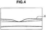
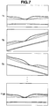
- Fig. 4 illustrate an example of a tomographic image captured in a state where the pupillary center of the anterior ocular segment Ea of the subject's eye E coincides with the optical axis of the objective lens 101-1.
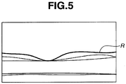
- Fig. 5 illustrate an example of a tomographic image captured in a state where the pupillary center is deviated by about 1 millimeter in the X direction with respect to the optical axis of the objective lens 101-1.
- a retina R is deviated in the X direction in comparison with the tomographic image illustrated in Fig. 4 .
- the tomographic image itself has not largely changed in shape. This kind of deviation in the X direction can be corrected by the above-described fundus tracking.
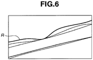
- Fig. 6 illustrates an example of a tomographic image captured in the state illustrated in Fig. 5 except that automatic alignment is activated so that the pupillary center coincides with the optical axis of the objective lens 101-1.
- a deviation in the X direction arises and further the retina R is largely inclined. This kind of inclination of the retina R cannot be corrected by fundus tracking.
- Fig. 7 illustrates an example display of a virtual tomographic image perpendicularly intersecting with the main scanning direction, generated by reconfiguring the 128 tomographic images illustrated in Fig. 7 .
- the retina R has largely changed in shape.
- the optical coherence tomographic imaging apparatus suspends automatic alignment during execution of scans for capturing a plurality of tomographic images. This operation will be described below with reference to the flowchart illustrated in Fig. 9 .
- the inspector Prior to image capturing, the inspector makes the subject sit down in front of the apparatus.
- the control unit 300 drives at least either one of the X scanner 122-1 and the Y scanner 122-2 as a scanning unit to switch between observation scan for capturing a tomographic image (hereinafter referred to as a tomographic image for observation) for subject's eye observation and recording scan for capturing a tomographic image (hereinafter referred to as a tomographic image for recording) for subject's eye state recording.
- step S901 upon reception of a switch operation (not illustrated) by the inspector, the control unit 300 starts automatic alignment.
- step S902 to observe alignment conditions, the control unit 300 starts capturing an observation tomographic image of the fundus Er.
- step S903 the control unit 300 displays the acquired observation tomographic image on the monitor 301.
- the inspector can determine right and wrong of alignment conditions with reference to the observation tomographic image displayed on the monitor 301. In a case the inspector determines that alignment conditions are right, the inspector operates a switch (not illustrated) on the control unit 300 to instruct to start tomographic image capturing.
- step S904 in response to a switch operation (not illustrated) by the inspector, the control unit 300 starts capturing tomographic images for recording.
- step S905 upon reception of an image capturing start instruction, the control unit 300 suspends automatic alignment before starting image capturing for recording.
- step S906 the control unit 300 starts scanning for generating a plurality of tomographic images for recording. Specifically, the control unit 300 controls at least either one of the X scanner 122-1 and the Y scanner 122-2 to perform scanning on an arbitrary locus a plurality of times.
- step S907 upon completion of all scans, the control unit 300 restarts automatic alignment.
- step S908 the control unit 300 generates a plurality of tomographic images corresponding to the plurality of scans.
- step S909 the control unit 300 records the plurality of tomographic images generated in step S908 in a recording medium (not illustrated). This completes the processing of the flowchart illustrated in Fig. 9 .
- automatic alignment is suspended immediately before starting scans for acquiring tomographic images for recording
- automatic alignment may be suspended before that timing.
- automatic alignment may be suspended when the pupillary position of the subject's eye E is determined to almost coincide with the optical axis of the optical system through automatic alignment.
- a reception unit for receiving a signal for acquiring a plurality of tomographic images may be provided, and the processing for tomographic image acquisition may be started after reception of the signal.
- control unit 300 suspends automatic alignment at least when generating tomographic images for recording, enabling acquiring suitable tomographic images having less distortion.
- the captured tomographic image is largely affected.
- the acquisition of one tomographic image takes 14.6 milliseconds. Therefore, in a case acquiring a plurality of tomographic images, the control unit 300 scans the fundus Er a plurality of times with a period of about 14.6 milliseconds. This interval depends on the number of A scans required to form one tomographic image, and on the time required to acquire one A scan.
- the period of scanning position correction through fundus tracking is 33.3 milliseconds. This period depends on the acquisition interval of fundus observation images of the fundus Er which is used to calculate the amount of displacement for scanning position correction.
- the scanning position correction is performed at long intervals, actual correction is performed at very high speed. Therefore, the operation of fundus tracking is performed in such a way that scanning position correction is instantaneously carried out in response to all of eye movements occurring within the correction intervals. Therefore, in a case scanning position correction through fundus tracking is performed during the scan on the fundus Er to acquire one tomographic image, a gap G of the retina layer will appear, as illustrated in Fig. 11 .
- the gap G of the retina layer not only disturbs diagnosis but also leads to misdiagnosis.
- the control unit 300 when capturing a plurality of tomographic images, the control unit 300 performs scanning position correction through fundus tracking between scans for each tomographic image acquisition, and suspends the scanning position correction during scan. This operation will be described below with reference to the flowchart illustrated in Fig. 12 .
- the inspector Prior to image capturing, the inspector makes the subject sit down in front of the apparatus.
- the control unit 300 can drive at least either one of the X scanner 122-1 and the Y scanner 122-2 as a scanning unit to switch between observation scan for capturing a tomographic image for subject's eye observation and recording scan for capturing a tomographic image for subject's eye state recording.
- step S1201 upon reception of a switch operation (not illustrated) by the inspector, the control unit 300 starts automatic alignment. Then, to observe alignment conditions, the control unit 300 starts capturing an observation tomographic image of the fundus Er. In step S1202, the control unit 300 displays the acquired observation tomographic image on the monitor 301. The inspector can determine right or wrong of alignment conditions with reference to the observation tomographic image displayed on the monitor 301.
- step S1203 the inspector determines that alignment conditions are right, and, upon reception of a switch operation (not illustrated), the control unit 300 starts capturing tomographic images for recording.
- steps S1201 to S1203 to adjust a coherence gate, the control unit 300 may perform scanning position correction based on fundus tracking.
- step S1204 the control unit 300 drives at least either one of the X scanner 122-1 and the Y scanner 122-2 as a scanning unit to start a scan on an arbitrary locus.
- step S1205 the control unit 300 functions as a fundus image acquisition unit, and determines whether a captured fundus image has been acquired. In a case it is determined that a fundus image has been acquired (YES in step S1205), the processing proceeds to step S1206. On the other hand, in a case it is determined that a fundus image has not been acquired (NO in step S1205), the processing proceeds to step S1208.
- control unit 300 functions as a movement amount calculation unit, and calculates the amount of fundus Er movement based on fundus images already acquired and newly acquired.
- step S1207 the control unit 300 stores in memory (not illustrated) information indicating that the fundus Er movement was detected during a scan, and information indicating the amount of the detected fundus Er movement. Then, the processing proceeds to step S1208. In step S1208, the control unit 300 ends a scan.
- step S1209 based on the information stored in memory (not illustrated), the control unit 300 determines whether the fundus Er movement has been detected during execution of a scan. In a case it is determined that the fundus Er movement has been detected (YES in step S1209), the processing proceeds to step S1210. On the other hand, in a case it is determined that the fundus Er movement has not been detected (NO in step S1209), the processing proceeds to step S1212.
- step S1210 the control unit 300 reads the calculated amount of fundus Er movement from memory (not illustrated).
- step S1211 the control unit 300 calculates the next scanning starting position corrected by offsetting the amount of fundus Er movement, and moves the the next scanning position to the offset scanning starting position.
- step S1212 the control unit 300 drives at least either one of the X scanner 122-1 and the Y scanner 122-2 as a scanning unit to move the scanning position to the next scanning starting position.
- step S1213 the control unit 300 determines whether a series of scans is completed. In a case a series of scans is determined to be completed (YES in step S1213), the processing proceeds to step S1214. On the other hand, in a case it is determined that the next scan has not been performed (NO in step S1213), the processing returns to step S1204. In step S1204, the control unit 300 repeats a series of fundus tracking.
- step S1214 the control unit 300 generates a plurality of tomographic images for recording corresponding to a series of a plurality of scans.
- step S1215 the control unit 300 displays the plurality of tomographic images for recording generated in step S1214 on the monitor 301. This completes the processing of the flowchart illustrated in Fig. 12 .
- the control unit 300 suspends the scanning position correction during a scan, and performs scanning position correction between a scan and the next scan.
- the control unit 300 may control the scanning unit to perform the scanning position correction during sub scan by the scanning unit, and to suspend the scanning position correction during main scan by the scanning unit.
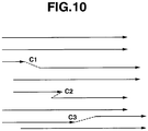
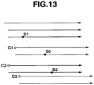
- the following describes an example of scanning in which the control unit 300 scans the fundus Er a plurality of times while performing fundus tracking according to the flowchart illustrated in Fig. 12 , with reference to Fig. 13 .
- the scanning position correction accompanying the fundus Er movement detected at the timing D1 is delayed till the next scan is started at the timing C1.
- the scanning position correction accompanying the fundus Er movement detected at timings D2 and D3 is delayed till timings C2 and C3, respectively.
- control in this way enables completely and continuously scanning the fundus Er of the subject's eye E without interruption. Therefore, it is possible to reduce the possibility that the gap G of the retina layer as illustrated in Fig. 11 appears on a captured tomographic image for recording.
- the scanning position is not corrected, and therefore the possibility that the gap G of the retina layer appears is low.
- the control unit 300 may remove tomographic images acquired by scans at the timings D1, D2, and D3, or perform again the same scans at respective scanning positions to capture tomographic images again. Thus, tomographic images having less distortion can be acquired.
- the control unit 300 may parallelly perform the automatic alignment suspending processing and the automatic alignment restart processing in steps S905 and S907, respectively, illustrated in Fig. 9 .
- the control unit 300 may perform the alignment suspending processing in step S905 between the processing in step S1203 and the processing in step S1204, and perform the alignment restart processing in step S907 between the processing in step S1213 and the processing in step S1214.
- the control unit 300 may perform at least either one of the automatic alignment processing illustrated in Fig. 9 and the scanning position correction processing based on fundus tracking illustrated in Fig. 12 .
- control unit 300 performs control to perform scanning position correction between scans (between a scan and the next scan) when acquiring a tomographic image for recording
- the control unit 300 may perform similar control also when acquiring a tomographic image for observation.
- a distortion of the retina layer can be reduced also in tomographic images for observation.
- the control unit 300 may perform scanning position correction when the fundus Er movement is detected.
- Tomographic images for observation are displayed as a real-time observation moving image, and therefore the display period is very short. Further, tomographic images for observation are not used for diagnosis, and therefore a distortion of the retina layer is permissible to a certain extent.
- the control unit 300 suspends at least either one of the alignment of the optical system relative to the subject's eye for capturing an image of the subject's eye and the scanning position correction through fundus tracking of the subject's eye.
- tomographic images having less distortion can be acquired.
- FIGs. 14A and 14B illustrate examples of configurations of an optical coherence tomographic imaging apparatus according to the second exemplary embodiment.
- FIG. 14A is almost similar to the configuration illustrated in Fig. 1 , an optical path L16 is disposed instead of the optical path L2.
- the configuration illustrated in Fig. 14A uses a CCD instead of an APD to acquire fundus observation images.
- a lens 1601, a perforated mirror 1602, lens 1605 and 1606, and a dichroic mirror 1607 are disposed on the optical path L16 in this order.
- a lens 1603 and a fundus observation light source 1604 are disposed on the reflection side of the perforated mirror 1602.
- the dichroic mirror 1607 transmits a wavelength in the vicinity of the fundus observation light source 1604, specifically, 780 nanometers.
- a fundus observation CCD 1608 is disposed on the penetration side, and a fixation lamp light source 116 is disposed on the reflection side.
- the lens 1605 is driven by a motor (not illustrated) for focusing adjustment for the fixation lamp and fundus observation.
- the CCD 1608 has sensitivity in the vicinity of the wavelength of the fundus observation light source 1604.
- Fundus images acquired by the CCD 1508 can be handled in a similar way to fundus images in the first exemplary embodiment. Therefore, the control unit 300 controls fundus tracking, detection of the amount of movement, and the scanning position correction in a similar way to the first exemplary embodiment.
- a CCD is used, a CMOS or other two-dimensional sensors may be used.
- a computer 300 performs the FFT processing on a signal of a line sensor 204, and performs control to generate information in the depth direction at a certain point on the fundus Er.
- this information in the depth direction is used to acquire a tomogram image.
- this information in the depth direction is accumulated for use as information indicating the state of a certain point on the fundus Er.
- control unit 300 can accumulate the information in the depth direction at each point within a 10-mm range in the X direction, and repeats the relevant processing 128 times to acquire the state of each point within a 10 mm x 10 mm range on the fundus Er. By converting the information into density and luminance, an image indicating the state of the fundus within the above-described range can be acquired.
- this image as a fundus observation image enables scanning position correction between scans in a similar way to the first exemplary embodiment.
- the control unit 300 since the control unit 300 needs to control the X scanner 122-1 and the Y scanner 122-2 to acquire a fundus observation image, the control unit 300 cannot perform scan for tomographic image acquisition during fundus observation image acquisition. The control unit 300 needs to perform fundus observation image acquisition between each of the scans.
- the present exemplary embodiment since neither a dedicated fundus observation light source nor a fundus observation sensor is provided, there is an advantage that the cost of the apparatus can be reduced.
- Fig. 15 is a flowchart illustrating an example of fundus tracking control according to a third exemplary embodiment.
- the control unit 300 performs alignment of the subject's eye, fundus tracking, and tomographic image capturing in a similar way to the first exemplary embodiment.
- the control unit 300 performs scanning position correction between a scan and the next scan based on the relevant amount of movement. Further, in a case the mount of subject's eye movement before a scan exceeds the threshold value, the control unit 300 restarts scan of the scanning unit from a scanning position before a scan.
- the control unit 300 may not perform scanning position correction in time. Then, a first distortion arises in the tomographic image caused by the fundus Er movement, and then a second distortion arises due to scanning position correction at delayed timing. In this way, the scanning position correction may increase the number of tomographic image distortions. To solve this problem, the control unit 300 restarts scan from a scan before the fundus Er movement occurs. Thus, tomographic images having less distortion can be acquired.
- Fig. 15 is a flowchart illustrating processing for restarting scan by the scanning unit.
- the flowchart illustrated in Fig. 15 is almost identical to the flowchart illustrated in Fig. 12 except that steps S1401 and S1402 are added.
- the control unit 300 performs scanning position correction in a similar way to the first exemplary embodiment.
- the control unit 300 as an example of a determination unit determines whether the amount of subject's eye movement before a scan by the scanning unit exceeds a threshold value. This amount of movement refers to the amount of fundus Er movement occurring during N scans.
- the value of N is an apparatus-specific value and is determined by the frame rate for fundus image acquisition, the frame rate for scan, and the fundus image processing time.
- N is about 5.
- the threshold value of the amount of fundus Er movement is determined by the resolution of the apparatus between the scans and the frame rate for fundus image acquisition. In the present exemplary embodiment, the threshold value is about 10 to 100 micrometers. In a case the amount of fundus Er movement is determined to be smaller than the threshold value (NO in step S1401), then in step S1212, the control unit 300 performs processing in subsequent steps in a similar way to the first exemplary embodiment. On the other hand, in a case the amount of fundus Er movement is determined to be equal to or greater than the threshold value (YES in step S1401), then in step S1402, the control unit 300 offsets the scanning starting position.
- the control unit 300 performs this offsetting of the past N scans in a backward direction. For example, in the present exemplary embodiment, the control unit 300 repeats 128 times a 10-mm scan in the X direction on the fundus Er while shifting each scan by 0.078 millimeters in the Y direction. In this case, the offset is 0.078 x N millimeters in the Y direction. In this way, the control unit 300 achieves control for restarting scan from a past scan.
- control unit 300 restarts scan from a scan before a tomographic image distortion occurs.
- tomographic images having less distortion can be acquired.
- a fourth exemplary embodiment will be described below.
- the apparatus configuration according to the present exemplary embodiment is similar to that according to the first exemplary embodiment, and redundant descriptions thereof will be omitted.
- the control unit 300 performs alignment of the subject's eye, fundus tracking, and tomographic image capturing in a similar way to the first exemplary embodiment.
- the present exemplary embodiment differs from the first exemplary embodiment in that it detects the amount of fundus Er rotation in addition to the amount of fundus Er movement.
- the control unit 300 since the control unit 300 detects the amount of fundus Er movement in the X and Y directions to perform scanning position correction, a tomographic image may not provide a straight line on the fundus Er if the angle of the subject's eye E changes during processing. Then, the control unit 300 detects the amount of fundus rotation to correct the rotational direction of scan.
- the control unit 300 detects the amount of fundus rotation as follows.
- the control unit 300 sets two target regions on each fundus observation image, and detects respective target regions in the previous fundus observation image and the current fundus observation image.
- the coordinates of the target regions detected in the previous fundus observation image are A1 (xa1, ya1) and B1 (xb1, yb1)
- the coordinates of the target regions detected in the current fundus observation image are A2 (xa2, ya2) and B2 (xb2, yb2).
- A2 indicates the same target region as A1
- B2 indicates the same target region as B1.
- the coordinate transformation based on the combination of parallel translation, and rotation in the two-dimensional coordinates are represented by an affine transformation matrix.
- the control unit 300 performs the coordinate transformation from the coordinates of the previous fundus observation image into the coordinates of the current fundus observation image as follows. First, the control unit 300 performs parallel translation so that the target region A1 coincides with the origin (0, 0). The control unit 300 sets a vector (tx1, ty1) for representing this translation.
- x ′ y ′ 1 1 0 tx 2 0 1 ty 2 0 0 1 cos ⁇ ⁇ ⁇ sin ⁇ ⁇ 0 sin ⁇ ⁇ cos ⁇ ⁇ 0 0 0 1 1 0 tx 1 0 1 ty 1 0 0 1 x y 1
- (x, y) indicates the coordinates before transformation
- (x', y') indicates the coordinates to be acquired after transformation.
- the control unit 300 performs coordinate transformation for all of subsequent scans by using this coordinate transformation matrix.
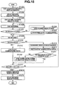
- Fig. 16 illustrates a flowchart to which processing for correcting the amount of fundus rotation is added.
- the control unit 300 After a fundus image has been acquired, in step S1501, the control unit 300 detects the target regions A and B.
- the control unit 300 stores the coordinates of the detected target regions in memory.
- the control unit 300 reads the coordinates of the target regions A and B from memory.
- step S1504 based on the coordinates (A1, B1, A2, B2) of the target regions A and B, the control unit 300 generates a coordinate transformation matrix through the affine transformation.
- step 1505 the control unit 300 transforms the coordinates of subsequent scans by using the generated coordinate transformation matrix.
- the control unit 300 can continue scanning so that the scan locus forms a straight line on the fundus Er.
- a fifth exemplary embodiment will be described below.
- the apparatus configuration according to the present exemplary embodiment is similar to that according to the second exemplary embodiment, and redundant descriptions thereof will be omitted.
- the control unit 300 detects the amount of fundus Er movement, detects a blink of the subject's eye, and stores and reads coordinates in/from memory according to the flowchart illustrated in Fig. 15 . Further, the condition in step S1401 is changed to "amount of fundus movement ⁇ threshold value, or is a subject's eye blink detected?". Processing for other control is similar to that according to the third exemplary embodiment.
- the control unit 300 determines a blink of the subject's eye as follows. First, the control unit 300 as an example of a detection unit detects the target regions described in the first exemplary embodiment in a plurality of fundus observation images acquired in succession. In a case the detection of the target region fails once or a plurality of times in succession, and then the detection of the same target region is successfully completed once or a plurality of times in succession, the control unit 300 determines that the subject's eye Er has blinked.
- the upper and the lower limits of the number of times of successive success or failure are apparatus-specific values which are determined by comparing the frame rate for fundus observation image acquisition with the blinking time of a healthy eye.
- the control unit 300 can return to a scan before the blink and then restart scan. Therefore, even if a blink causes information loss and suitable tomographic image acquisition fails, the above-described control enables acquiring of suitable tomographic images without information loss.
- the control unit 300 may detects a blink by using anterior ocular segment images for the subject's eye. For example, the control unit 300 may determine the detection of a blink in a case the area of the pupillary region in the anterior ocular segment image is smaller than a threshold value.
- Embodiments of the present invention can also be realized by a computer of a system or apparatus that reads out and executes computer executable instructions recorded on a storage medium (e.g., non-transitory computer-readable storage medium) to perform the functions of one or more of the above-described embodiment(s) of the present invention, and by a method performed by the computer of the system or apparatus by, for example, reading out and executing the computer executable instructions from the storage medium to perform the functions of one or more of the above-described embodiment(s).
- the computer may comprise one or more of a central processing unit (CPU), micro processing unit (MPU), or other circuitry, and may include a network of separate computers or separate computer processors.
- the computer executable instructions may be provided to the computer, for example, from a network or the storage medium.
- the storage medium may include, for example, one or more of a hard disk, a random-access memory (RAM), a read only memory (ROM), a storage of distributed computing systems, an optical disk (such as a compact disc (CD), digital versatile disc (DVD), or Blu-ray Disc (BD)TM), a flash memory device, a memory card, and the like.
Landscapes
- Health & Medical Sciences (AREA)
- Life Sciences & Earth Sciences (AREA)
- Engineering & Computer Science (AREA)
- Surgery (AREA)
- General Health & Medical Sciences (AREA)
- Biophysics (AREA)
- Biomedical Technology (AREA)
- Heart & Thoracic Surgery (AREA)
- Medical Informatics (AREA)
- Molecular Biology (AREA)
- Physics & Mathematics (AREA)
- Animal Behavior & Ethology (AREA)
- Ophthalmology & Optometry (AREA)
- Public Health (AREA)
- Veterinary Medicine (AREA)
- Nuclear Medicine, Radiotherapy & Molecular Imaging (AREA)
- Radiology & Medical Imaging (AREA)
- Human Computer Interaction (AREA)
- Signal Processing (AREA)
- Eye Examination Apparatus (AREA)
- Investigating Or Analysing Materials By Optical Means (AREA)
Applications Claiming Priority (1)
| Application Number | Priority Date | Filing Date | Title |
|---|---|---|---|
| JP2013017661A JP6460618B2 (ja) | 2013-01-31 | 2013-01-31 | 光干渉断層撮像装置およびその制御方法 |
Publications (3)
| Publication Number | Publication Date |
|---|---|
| EP2762060A2 EP2762060A2 (en) | 2014-08-06 |
| EP2762060A3 EP2762060A3 (en) | 2016-12-28 |
| EP2762060B1 true EP2762060B1 (en) | 2020-03-11 |
Family
ID=50023406
Family Applications (1)
| Application Number | Title | Priority Date | Filing Date |
|---|---|---|---|
| EP14000250.2A Active EP2762060B1 (en) | 2013-01-31 | 2014-01-24 | Optical coherence tomographic imaging apparatus and method for controlling the same |
Country Status (4)
| Country | Link |
|---|---|
| US (2) | US9211062B2 (enExample) |
| EP (1) | EP2762060B1 (enExample) |
| JP (1) | JP6460618B2 (enExample) |
| CN (2) | CN105942968B (enExample) |
Families Citing this family (33)
| Publication number | Priority date | Publication date | Assignee | Title |
|---|---|---|---|---|
| JP6217085B2 (ja) * | 2013-01-23 | 2017-10-25 | 株式会社ニデック | 眼科撮影装置 |
| JP6184114B2 (ja) * | 2013-01-31 | 2017-08-23 | キヤノン株式会社 | 光干渉断層撮像装置およびその制御方法 |
| JP6224908B2 (ja) * | 2013-04-17 | 2017-11-01 | キヤノン株式会社 | 撮像装置 |
| JP6207221B2 (ja) * | 2013-04-30 | 2017-10-04 | キヤノン株式会社 | 光断層撮像装置 |
| JP6557229B2 (ja) * | 2014-07-01 | 2019-08-07 | 興和株式会社 | 断層像撮影装置 |
| JP6444080B2 (ja) * | 2014-07-14 | 2018-12-26 | キヤノン株式会社 | Oct装置およびその制御方法 |
| DE112015004581B4 (de) | 2014-10-06 | 2024-02-22 | Carl Zeiss Meditec Ag | Operationssystem mit einer OCT-Einrichtung |
| DE102014222629A1 (de) * | 2014-11-05 | 2016-05-12 | Carl Zeiss Meditec Ag | Untersuchen eines Objekts mit OCT-Abtastlichtstrahlen |
| DE202014011051U1 (de) | 2014-11-05 | 2017-07-26 | Carl Zeiss Meditec Ag | Vorrichtung für das Untersuchen eines Patientenauges |
| DE202014011050U1 (de) | 2014-11-05 | 2017-07-26 | Carl Zeiss Meditec Ag | Vorrichtung für das Untersuchen eines Patientenauges |
| EP3081146B1 (en) * | 2015-04-15 | 2019-10-30 | Novartis AG | An apparatus for modelling ocular structures |
| CN104997482B (zh) * | 2015-08-04 | 2016-08-24 | 深圳市莫廷影像技术有限公司 | 一种直线高清扫描随访实现方法及装置 |
| KR101746763B1 (ko) | 2016-02-01 | 2017-06-14 | 한국과학기술원 | 망막 또는 맥락막 내 혈관조영 광가간섭 단층촬영 장치 및 이를 이용한 질병 진단방법 |
| US10832051B1 (en) * | 2016-06-13 | 2020-11-10 | Facebook Technologies, Llc | Eye tracking using optical coherence methods |
| WO2018079326A1 (ja) * | 2016-10-28 | 2018-05-03 | 富士フイルム株式会社 | 光干渉断層画像撮像装置および計測方法 |
| CN108662992B (zh) * | 2017-03-31 | 2020-10-16 | 均豪精密工业股份有限公司 | 表面量测方法及表面量测系统 |
| EP3654826A4 (en) * | 2017-07-17 | 2021-03-24 | Welch Allyn, Inc. | THROUGH-FOCUS RETINAL IMAGE CAPTURE |
| JP6923392B2 (ja) * | 2017-08-28 | 2021-08-18 | 株式会社トプコン | 眼科装置 |
| JP2019041841A (ja) * | 2017-08-30 | 2019-03-22 | 株式会社トプコン | 眼科装置、及びその制御方法 |
| JP7314345B2 (ja) * | 2017-08-30 | 2023-07-25 | 株式会社トプコン | 眼科装置、及びその制御方法 |
| JP7192204B2 (ja) * | 2017-09-29 | 2022-12-20 | 株式会社ニデック | 眼科撮影装置 |
| US10963046B1 (en) | 2018-05-17 | 2021-03-30 | Facebook Technologies, Llc | Drift corrected eye tracking |
| CN110215184B (zh) * | 2019-06-28 | 2020-11-20 | 南京博视医疗科技有限公司 | 一种眼底相机的闭环控制系统及其方法 |
| CN110301886B (zh) * | 2019-06-28 | 2020-11-27 | 南京博视医疗科技有限公司 | 一种实时闭环控制眼底相机的光学系统及其实现方法 |
| FR3099876B1 (fr) * | 2019-08-12 | 2025-03-21 | Imagine Eyes | Procédé et dispositif d’imagerie rétinienne tomographique en cohérence optique |
| CN110686865A (zh) * | 2019-10-18 | 2020-01-14 | 南昌航空大学 | 一种基于oct技术的光纤熔接结构及损耗云检测系统 |
| JP2023512347A (ja) * | 2020-01-27 | 2023-03-24 | ブドゥ、カロリヌ | マルチモード干渉装置および方法 |
| CN111714080B (zh) * | 2020-06-30 | 2021-03-23 | 重庆大学 | 一种基于眼动信息的疾病分类系统 |
| ES2970267T3 (es) * | 2020-11-12 | 2024-05-27 | Optos Plc | Procesamiento de datos de imagen OCT volumétrica |
| CN113040701B (zh) * | 2021-03-11 | 2024-05-28 | 视微影像(河南)科技有限公司 | 一种三维眼动追踪系统及其追踪方法 |
| CN113040700B (zh) * | 2021-03-11 | 2024-05-28 | 视微影像(河南)科技有限公司 | 一种眼动追踪系统及其追踪方法 |
| JP2024007132A (ja) * | 2022-07-05 | 2024-01-18 | 株式会社ニデック | 眼科撮影装置および眼科撮影制御プログラム |
| CN120240989A (zh) * | 2025-05-29 | 2025-07-04 | 山西医科大学 | 一种基于眼动门控的视神经扫描监控的方法及系统 |
Family Cites Families (23)
| Publication number | Priority date | Publication date | Assignee | Title |
|---|---|---|---|---|
| US7145661B2 (en) * | 2003-12-31 | 2006-12-05 | Carl Zeiss Meditec, Inc. | Efficient optical coherence tomography (OCT) system and method for rapid imaging in three dimensions |
| EP1602321A1 (en) | 2004-06-02 | 2005-12-07 | SensoMotoric Instruments GmbH | Method and apparatus for image-based eye tracking for retinal diagnostic or surgery device |
| JP4822969B2 (ja) | 2006-07-27 | 2011-11-24 | 株式会社ニデック | 眼科撮影装置 |
| JP5089940B2 (ja) | 2006-08-29 | 2012-12-05 | 株式会社トプコン | 眼球運動測定装置、眼球運動測定方法及び眼球運動測定プログラム |
| JP4466968B2 (ja) | 2008-11-10 | 2010-05-26 | キヤノン株式会社 | 画像処理装置、画象処理方法、プログラム、及びプログラム記憶媒体 |
| JP5437755B2 (ja) | 2009-04-15 | 2014-03-12 | 株式会社トプコン | 眼底観察装置 |
| JP5704879B2 (ja) * | 2009-09-30 | 2015-04-22 | 株式会社ニデック | 眼底観察装置 |
| JP5378157B2 (ja) * | 2009-10-27 | 2013-12-25 | 株式会社トプコン | 眼科観察装置 |
| JP5213835B2 (ja) | 2009-11-17 | 2013-06-19 | キヤノン株式会社 | 光干渉断層像の撮像方法および光干渉断層像の撮像装置 |
| JP5570195B2 (ja) | 2009-12-07 | 2014-08-13 | 株式会社ニデック | Oct装置 |
| JP5025715B2 (ja) * | 2009-12-08 | 2012-09-12 | キヤノン株式会社 | 断層画像撮影装置、画像処理装置、画像処理システム、画像処理装置の制御方法及びプログラム |
| JP5416577B2 (ja) * | 2009-12-25 | 2014-02-12 | 株式会社ニデック | 網膜機能計測装置 |
| JP5783681B2 (ja) * | 2010-03-31 | 2015-09-24 | キヤノン株式会社 | 撮像装置及び撮像方法 |
| WO2011139895A1 (en) | 2010-04-29 | 2011-11-10 | Massachusetts Institute Of Technology | Method and apparatus for motion correction and image enhancement for optical coherence tomography |
| JP5297415B2 (ja) | 2010-04-30 | 2013-09-25 | キヤノン株式会社 | 眼科装置及び眼科方法 |
| JP5818409B2 (ja) | 2010-06-17 | 2015-11-18 | キヤノン株式会社 | 眼底撮像装置及びその制御方法 |
| JP5864910B2 (ja) * | 2010-07-16 | 2016-02-17 | キヤノン株式会社 | 画像取得装置及び制御方法 |
| JP5704946B2 (ja) * | 2011-02-04 | 2015-04-22 | 株式会社ニデック | 眼科撮影装置 |
| JP5917004B2 (ja) * | 2011-03-10 | 2016-05-11 | キヤノン株式会社 | 撮像装置及び撮像装置の制御方法 |
| US9033510B2 (en) * | 2011-03-30 | 2015-05-19 | Carl Zeiss Meditec, Inc. | Systems and methods for efficiently obtaining measurements of the human eye using tracking |
| CA2834289A1 (en) * | 2011-04-29 | 2012-11-01 | Optovue, Inc. | Improved imaging with real-time tracking using optical coherence tomography |
| WO2013004801A1 (en) * | 2011-07-07 | 2013-01-10 | Carl Zeiss Meditec Ag | Improved data acquisition methods for reduced motion artifacts and applications in oct angiography |
| JP2014045868A (ja) * | 2012-08-30 | 2014-03-17 | Canon Inc | インタラクティブ制御装置 |
-
2013
- 2013-01-31 JP JP2013017661A patent/JP6460618B2/ja not_active Expired - Fee Related
-
2014
- 2014-01-22 US US14/161,498 patent/US9211062B2/en not_active Expired - Fee Related
- 2014-01-24 EP EP14000250.2A patent/EP2762060B1/en active Active
- 2014-01-29 CN CN201610391494.XA patent/CN105942968B/zh not_active Expired - Fee Related
- 2014-01-29 CN CN201410043344.0A patent/CN103961058B/zh not_active Expired - Fee Related
-
2015
- 2015-11-04 US US14/932,843 patent/US9730581B2/en active Active
Non-Patent Citations (1)
| Title |
|---|
| None * |
Also Published As
| Publication number | Publication date |
|---|---|
| EP2762060A3 (en) | 2016-12-28 |
| CN105942968B (zh) | 2018-07-03 |
| US20160051139A1 (en) | 2016-02-25 |
| US9730581B2 (en) | 2017-08-15 |
| US9211062B2 (en) | 2015-12-15 |
| JP2014147503A (ja) | 2014-08-21 |
| JP6460618B2 (ja) | 2019-01-30 |
| CN103961058A (zh) | 2014-08-06 |
| CN105942968A (zh) | 2016-09-21 |
| US20140211155A1 (en) | 2014-07-31 |
| CN103961058B (zh) | 2016-06-22 |
| EP2762060A2 (en) | 2014-08-06 |
Similar Documents
| Publication | Publication Date | Title |
|---|---|---|
| EP2762060B1 (en) | Optical coherence tomographic imaging apparatus and method for controlling the same | |
| KR101571924B1 (ko) | 광 간섭 단층 촬상 장치, 광 간섭 단층 촬상 장치 제어 방법 및 저장 매체 | |
| KR101630239B1 (ko) | 안과장치, 안과장치의 제어방법, 및 기억매체 | |
| US9554700B2 (en) | Optical coherence tomographic imaging apparatus and method of controlling the same | |
| KR101477591B1 (ko) | 광학 단층촬영 화상 촬상장치 및 그 제어 방법 | |
| JP2020044027A (ja) | 眼科装置、その制御方法、プログラム、及び記録媒体 | |
| US10123699B2 (en) | Ophthalmologic apparatus and imaging method | |
| JP6274728B2 (ja) | 光干渉断層撮像装置およびその制御方法 | |
| JP5649679B2 (ja) | 光干渉断層撮像装置、光干渉断層撮像装置の制御方法、およびプログラム | |
| JP6486427B2 (ja) | 光干渉断層撮像装置およびその制御方法 | |
| JP2021087762A (ja) | 光干渉断層撮像装置、光干渉断層撮像装置の制御方法、およびプログラム | |
| JP2019054982A (ja) | 検査装置、該検査装置の制御方法、及びプログラム | |
| JP2019170807A (ja) | 撮像装置およびその制御方法 |
Legal Events
| Date | Code | Title | Description |
|---|---|---|---|
| PUAI | Public reference made under article 153(3) epc to a published international application that has entered the european phase |
Free format text: ORIGINAL CODE: 0009012 |
|
| 17P | Request for examination filed |
Effective date: 20140124 |
|
| AK | Designated contracting states |
Kind code of ref document: A2 Designated state(s): AL AT BE BG CH CY CZ DE DK EE ES FI FR GB GR HR HU IE IS IT LI LT LU LV MC MK MT NL NO PL PT RO RS SE SI SK SM TR |
|
| AX | Request for extension of the european patent |
Extension state: BA ME |
|
| PUAL | Search report despatched |
Free format text: ORIGINAL CODE: 0009013 |
|
| AK | Designated contracting states |
Kind code of ref document: A3 Designated state(s): AL AT BE BG CH CY CZ DE DK EE ES FI FR GB GR HR HU IE IS IT LI LT LU LV MC MK MT NL NO PL PT RO RS SE SI SK SM TR |
|
| AX | Request for extension of the european patent |
Extension state: BA ME |
|
| RIC1 | Information provided on ipc code assigned before grant |
Ipc: A61B 3/12 20060101ALI20161122BHEP Ipc: A61B 3/15 20060101ALI20161122BHEP Ipc: A61B 3/113 20060101ALI20161122BHEP Ipc: G06T 7/00 20060101ALI20161122BHEP Ipc: A61B 3/10 20060101AFI20161122BHEP |
|
| STAA | Information on the status of an ep patent application or granted ep patent |
Free format text: STATUS: REQUEST FOR EXAMINATION WAS MADE |
|
| R17P | Request for examination filed (corrected) |
Effective date: 20170628 |
|
| RBV | Designated contracting states (corrected) |
Designated state(s): AL AT BE BG CH CY CZ DE DK EE ES FI FR GB GR HR HU IE IS IT LI LT LU LV MC MK MT NL NO PL PT RO RS SE SI SK SM TR |
|
| GRAP | Despatch of communication of intention to grant a patent |
Free format text: ORIGINAL CODE: EPIDOSNIGR1 |
|
| STAA | Information on the status of an ep patent application or granted ep patent |
Free format text: STATUS: GRANT OF PATENT IS INTENDED |
|
| INTG | Intention to grant announced |
Effective date: 20190528 |
|
| GRAJ | Information related to disapproval of communication of intention to grant by the applicant or resumption of examination proceedings by the epo deleted |
Free format text: ORIGINAL CODE: EPIDOSDIGR1 |
|
| STAA | Information on the status of an ep patent application or granted ep patent |
Free format text: STATUS: REQUEST FOR EXAMINATION WAS MADE |
|
| INTC | Intention to grant announced (deleted) | ||
| GRAP | Despatch of communication of intention to grant a patent |
Free format text: ORIGINAL CODE: EPIDOSNIGR1 |
|
| STAA | Information on the status of an ep patent application or granted ep patent |
Free format text: STATUS: GRANT OF PATENT IS INTENDED |
|
| INTG | Intention to grant announced |
Effective date: 20191011 |
|
| GRAS | Grant fee paid |
Free format text: ORIGINAL CODE: EPIDOSNIGR3 |
|
| RAP1 | Party data changed (applicant data changed or rights of an application transferred) |
Owner name: CANON KABUSHIKI KAISHA |
|
| GRAA | (expected) grant |
Free format text: ORIGINAL CODE: 0009210 |
|
| STAA | Information on the status of an ep patent application or granted ep patent |
Free format text: STATUS: THE PATENT HAS BEEN GRANTED |
|
| AK | Designated contracting states |
Kind code of ref document: B1 Designated state(s): AL AT BE BG CH CY CZ DE DK EE ES FI FR GB GR HR HU IE IS IT LI LT LU LV MC MK MT NL NO PL PT RO RS SE SI SK SM TR |
|
| REG | Reference to a national code |
Ref country code: GB Ref legal event code: FG4D |
|
| REG | Reference to a national code |
Ref country code: CH Ref legal event code: EP |
|
| REG | Reference to a national code |
Ref country code: AT Ref legal event code: REF Ref document number: 1242119 Country of ref document: AT Kind code of ref document: T Effective date: 20200315 |
|
| REG | Reference to a national code |
Ref country code: DE Ref legal event code: R082 Ref document number: 602014062051 Country of ref document: DE Representative=s name: WESER & KOLLEGEN PATENTANWAELTE PARTMBB, DE |
|
| REG | Reference to a national code |
Ref country code: IE Ref legal event code: FG4D |
|
| REG | Reference to a national code |
Ref country code: DE Ref legal event code: R096 Ref document number: 602014062051 Country of ref document: DE |
|
| PG25 | Lapsed in a contracting state [announced via postgrant information from national office to epo] |
Ref country code: NO Free format text: LAPSE BECAUSE OF FAILURE TO SUBMIT A TRANSLATION OF THE DESCRIPTION OR TO PAY THE FEE WITHIN THE PRESCRIBED TIME-LIMIT Effective date: 20200611 Ref country code: FI Free format text: LAPSE BECAUSE OF FAILURE TO SUBMIT A TRANSLATION OF THE DESCRIPTION OR TO PAY THE FEE WITHIN THE PRESCRIBED TIME-LIMIT Effective date: 20200311 Ref country code: RS Free format text: LAPSE BECAUSE OF FAILURE TO SUBMIT A TRANSLATION OF THE DESCRIPTION OR TO PAY THE FEE WITHIN THE PRESCRIBED TIME-LIMIT Effective date: 20200311 |
|
| REG | Reference to a national code |
Ref country code: NL Ref legal event code: MP Effective date: 20200311 |
|
| PG25 | Lapsed in a contracting state [announced via postgrant information from national office to epo] |
Ref country code: HR Free format text: LAPSE BECAUSE OF FAILURE TO SUBMIT A TRANSLATION OF THE DESCRIPTION OR TO PAY THE FEE WITHIN THE PRESCRIBED TIME-LIMIT Effective date: 20200311 Ref country code: GR Free format text: LAPSE BECAUSE OF FAILURE TO SUBMIT A TRANSLATION OF THE DESCRIPTION OR TO PAY THE FEE WITHIN THE PRESCRIBED TIME-LIMIT Effective date: 20200612 Ref country code: BG Free format text: LAPSE BECAUSE OF FAILURE TO SUBMIT A TRANSLATION OF THE DESCRIPTION OR TO PAY THE FEE WITHIN THE PRESCRIBED TIME-LIMIT Effective date: 20200611 Ref country code: LV Free format text: LAPSE BECAUSE OF FAILURE TO SUBMIT A TRANSLATION OF THE DESCRIPTION OR TO PAY THE FEE WITHIN THE PRESCRIBED TIME-LIMIT Effective date: 20200311 Ref country code: SE Free format text: LAPSE BECAUSE OF FAILURE TO SUBMIT A TRANSLATION OF THE DESCRIPTION OR TO PAY THE FEE WITHIN THE PRESCRIBED TIME-LIMIT Effective date: 20200311 |
|
| REG | Reference to a national code |
Ref country code: LT Ref legal event code: MG4D |
|
| PG25 | Lapsed in a contracting state [announced via postgrant information from national office to epo] |
Ref country code: NL Free format text: LAPSE BECAUSE OF FAILURE TO SUBMIT A TRANSLATION OF THE DESCRIPTION OR TO PAY THE FEE WITHIN THE PRESCRIBED TIME-LIMIT Effective date: 20200311 |
|
| PG25 | Lapsed in a contracting state [announced via postgrant information from national office to epo] |
Ref country code: LT Free format text: LAPSE BECAUSE OF FAILURE TO SUBMIT A TRANSLATION OF THE DESCRIPTION OR TO PAY THE FEE WITHIN THE PRESCRIBED TIME-LIMIT Effective date: 20200311 Ref country code: CZ Free format text: LAPSE BECAUSE OF FAILURE TO SUBMIT A TRANSLATION OF THE DESCRIPTION OR TO PAY THE FEE WITHIN THE PRESCRIBED TIME-LIMIT Effective date: 20200311 Ref country code: EE Free format text: LAPSE BECAUSE OF FAILURE TO SUBMIT A TRANSLATION OF THE DESCRIPTION OR TO PAY THE FEE WITHIN THE PRESCRIBED TIME-LIMIT Effective date: 20200311 Ref country code: SM Free format text: LAPSE BECAUSE OF FAILURE TO SUBMIT A TRANSLATION OF THE DESCRIPTION OR TO PAY THE FEE WITHIN THE PRESCRIBED TIME-LIMIT Effective date: 20200311 Ref country code: PT Free format text: LAPSE BECAUSE OF FAILURE TO SUBMIT A TRANSLATION OF THE DESCRIPTION OR TO PAY THE FEE WITHIN THE PRESCRIBED TIME-LIMIT Effective date: 20200805 Ref country code: IS Free format text: LAPSE BECAUSE OF FAILURE TO SUBMIT A TRANSLATION OF THE DESCRIPTION OR TO PAY THE FEE WITHIN THE PRESCRIBED TIME-LIMIT Effective date: 20200711 Ref country code: SK Free format text: LAPSE BECAUSE OF FAILURE TO SUBMIT A TRANSLATION OF THE DESCRIPTION OR TO PAY THE FEE WITHIN THE PRESCRIBED TIME-LIMIT Effective date: 20200311 Ref country code: RO Free format text: LAPSE BECAUSE OF FAILURE TO SUBMIT A TRANSLATION OF THE DESCRIPTION OR TO PAY THE FEE WITHIN THE PRESCRIBED TIME-LIMIT Effective date: 20200311 |
|
| REG | Reference to a national code |
Ref country code: AT Ref legal event code: MK05 Ref document number: 1242119 Country of ref document: AT Kind code of ref document: T Effective date: 20200311 |
|
| REG | Reference to a national code |
Ref country code: DE Ref legal event code: R097 Ref document number: 602014062051 Country of ref document: DE |
|
| PLBE | No opposition filed within time limit |
Free format text: ORIGINAL CODE: 0009261 |
|
| STAA | Information on the status of an ep patent application or granted ep patent |
Free format text: STATUS: NO OPPOSITION FILED WITHIN TIME LIMIT |
|
| PG25 | Lapsed in a contracting state [announced via postgrant information from national office to epo] |
Ref country code: ES Free format text: LAPSE BECAUSE OF FAILURE TO SUBMIT A TRANSLATION OF THE DESCRIPTION OR TO PAY THE FEE WITHIN THE PRESCRIBED TIME-LIMIT Effective date: 20200311 Ref country code: IT Free format text: LAPSE BECAUSE OF FAILURE TO SUBMIT A TRANSLATION OF THE DESCRIPTION OR TO PAY THE FEE WITHIN THE PRESCRIBED TIME-LIMIT Effective date: 20200311 Ref country code: DK Free format text: LAPSE BECAUSE OF FAILURE TO SUBMIT A TRANSLATION OF THE DESCRIPTION OR TO PAY THE FEE WITHIN THE PRESCRIBED TIME-LIMIT Effective date: 20200311 Ref country code: AT Free format text: LAPSE BECAUSE OF FAILURE TO SUBMIT A TRANSLATION OF THE DESCRIPTION OR TO PAY THE FEE WITHIN THE PRESCRIBED TIME-LIMIT Effective date: 20200311 |
|
| 26N | No opposition filed |
Effective date: 20201214 |
|
| PG25 | Lapsed in a contracting state [announced via postgrant information from national office to epo] |
Ref country code: PL Free format text: LAPSE BECAUSE OF FAILURE TO SUBMIT A TRANSLATION OF THE DESCRIPTION OR TO PAY THE FEE WITHIN THE PRESCRIBED TIME-LIMIT Effective date: 20200311 Ref country code: SI Free format text: LAPSE BECAUSE OF FAILURE TO SUBMIT A TRANSLATION OF THE DESCRIPTION OR TO PAY THE FEE WITHIN THE PRESCRIBED TIME-LIMIT Effective date: 20200311 |
|
| PG25 | Lapsed in a contracting state [announced via postgrant information from national office to epo] |
Ref country code: MC Free format text: LAPSE BECAUSE OF FAILURE TO SUBMIT A TRANSLATION OF THE DESCRIPTION OR TO PAY THE FEE WITHIN THE PRESCRIBED TIME-LIMIT Effective date: 20200311 |
|
| REG | Reference to a national code |
Ref country code: CH Ref legal event code: PL |
|
| PG25 | Lapsed in a contracting state [announced via postgrant information from national office to epo] |
Ref country code: LU Free format text: LAPSE BECAUSE OF NON-PAYMENT OF DUE FEES Effective date: 20210124 |
|
| REG | Reference to a national code |
Ref country code: BE Ref legal event code: MM Effective date: 20210131 |
|
| PG25 | Lapsed in a contracting state [announced via postgrant information from national office to epo] |
Ref country code: LI Free format text: LAPSE BECAUSE OF NON-PAYMENT OF DUE FEES Effective date: 20210131 Ref country code: CH Free format text: LAPSE BECAUSE OF NON-PAYMENT OF DUE FEES Effective date: 20210131 |
|
| PG25 | Lapsed in a contracting state [announced via postgrant information from national office to epo] |
Ref country code: IE Free format text: LAPSE BECAUSE OF NON-PAYMENT OF DUE FEES Effective date: 20210124 |
|
| PG25 | Lapsed in a contracting state [announced via postgrant information from national office to epo] |
Ref country code: BE Free format text: LAPSE BECAUSE OF NON-PAYMENT OF DUE FEES Effective date: 20210131 |
|
| PGFP | Annual fee paid to national office [announced via postgrant information from national office to epo] |
Ref country code: FR Payment date: 20221220 Year of fee payment: 10 |
|
| PG25 | Lapsed in a contracting state [announced via postgrant information from national office to epo] |
Ref country code: HU Free format text: LAPSE BECAUSE OF FAILURE TO SUBMIT A TRANSLATION OF THE DESCRIPTION OR TO PAY THE FEE WITHIN THE PRESCRIBED TIME-LIMIT; INVALID AB INITIO Effective date: 20140124 |
|
| PG25 | Lapsed in a contracting state [announced via postgrant information from national office to epo] |
Ref country code: CY Free format text: LAPSE BECAUSE OF FAILURE TO SUBMIT A TRANSLATION OF THE DESCRIPTION OR TO PAY THE FEE WITHIN THE PRESCRIBED TIME-LIMIT Effective date: 20200311 |
|
| PG25 | Lapsed in a contracting state [announced via postgrant information from national office to epo] |
Ref country code: MK Free format text: LAPSE BECAUSE OF FAILURE TO SUBMIT A TRANSLATION OF THE DESCRIPTION OR TO PAY THE FEE WITHIN THE PRESCRIBED TIME-LIMIT Effective date: 20200311 |
|
| PG25 | Lapsed in a contracting state [announced via postgrant information from national office to epo] |
Ref country code: MT Free format text: LAPSE BECAUSE OF FAILURE TO SUBMIT A TRANSLATION OF THE DESCRIPTION OR TO PAY THE FEE WITHIN THE PRESCRIBED TIME-LIMIT Effective date: 20200311 |
|
| PG25 | Lapsed in a contracting state [announced via postgrant information from national office to epo] |
Ref country code: FR Free format text: LAPSE BECAUSE OF NON-PAYMENT OF DUE FEES Effective date: 20240131 |
|
| PG25 | Lapsed in a contracting state [announced via postgrant information from national office to epo] |
Ref country code: FR Free format text: LAPSE BECAUSE OF NON-PAYMENT OF DUE FEES Effective date: 20240131 |
|
| PGFP | Annual fee paid to national office [announced via postgrant information from national office to epo] |
Ref country code: GB Payment date: 20241219 Year of fee payment: 12 |
|
| PGFP | Annual fee paid to national office [announced via postgrant information from national office to epo] |
Ref country code: DE Payment date: 20241218 Year of fee payment: 12 |
|
| PG25 | Lapsed in a contracting state [announced via postgrant information from national office to epo] |
Ref country code: TR Free format text: LAPSE BECAUSE OF FAILURE TO SUBMIT A TRANSLATION OF THE DESCRIPTION OR TO PAY THE FEE WITHIN THE PRESCRIBED TIME-LIMIT Effective date: 20200311 |