EP2762004B1 - Nahrungsmittelknetgerät - Google Patents
Nahrungsmittelknetgerät Download PDFInfo
- Publication number
- EP2762004B1 EP2762004B1 EP13168946.5A EP13168946A EP2762004B1 EP 2762004 B1 EP2762004 B1 EP 2762004B1 EP 13168946 A EP13168946 A EP 13168946A EP 2762004 B1 EP2762004 B1 EP 2762004B1
- Authority
- EP
- European Patent Office
- Prior art keywords
- kneading
- spindle
- dough
- appliance
- stirring
- Prior art date
- Legal status (The legal status is an assumption and is not a legal conclusion. Google has not performed a legal analysis and makes no representation as to the accuracy of the status listed.)
- Active
Links
Images


Classifications
-
- A—HUMAN NECESSITIES
- A21—BAKING; EDIBLE DOUGHS
- A21C—MACHINES OR EQUIPMENT FOR MAKING OR PROCESSING DOUGHS; HANDLING BAKED ARTICLES MADE FROM DOUGH
- A21C1/00—Mixing or kneading machines for the preparation of dough
- A21C1/14—Structural elements of mixing or kneading machines; Parts; Accessories
- A21C1/1405—Tools
-
- A—HUMAN NECESSITIES
- A21—BAKING; EDIBLE DOUGHS
- A21C—MACHINES OR EQUIPMENT FOR MAKING OR PROCESSING DOUGHS; HANDLING BAKED ARTICLES MADE FROM DOUGH
- A21C1/00—Mixing or kneading machines for the preparation of dough
- A21C1/02—Mixing or kneading machines for the preparation of dough with vertically-mounted tools; Machines for whipping or beating
-
- A—HUMAN NECESSITIES
- A21—BAKING; EDIBLE DOUGHS
- A21C—MACHINES OR EQUIPMENT FOR MAKING OR PROCESSING DOUGHS; HANDLING BAKED ARTICLES MADE FROM DOUGH
- A21C1/00—Mixing or kneading machines for the preparation of dough
- A21C1/14—Structural elements of mixing or kneading machines; Parts; Accessories
- A21C1/1465—Drives
-
- A—HUMAN NECESSITIES
- A47—FURNITURE; DOMESTIC ARTICLES OR APPLIANCES; COFFEE MILLS; SPICE MILLS; SUCTION CLEANERS IN GENERAL
- A47J—KITCHEN EQUIPMENT; COFFEE MILLS; SPICE MILLS; APPARATUS FOR MAKING BEVERAGES
- A47J43/00—Implements for preparing or holding food, not provided for in other groups of this subclass
- A47J43/04—Machines for domestic use not covered elsewhere, e.g. for grinding, mixing, stirring, kneading, emulsifying, whipping or beating foodstuffs, e.g. power-driven
- A47J43/07—Parts or details, e.g. mixing tools, whipping tools
- A47J43/0716—Parts or details, e.g. mixing tools, whipping tools for machines with tools driven from the lower side
- A47J43/0722—Mixing, whipping or cutting tools
-
- A—HUMAN NECESSITIES
- A47—FURNITURE; DOMESTIC ARTICLES OR APPLIANCES; COFFEE MILLS; SPICE MILLS; SUCTION CLEANERS IN GENERAL
- A47J—KITCHEN EQUIPMENT; COFFEE MILLS; SPICE MILLS; APPARATUS FOR MAKING BEVERAGES
- A47J43/00—Implements for preparing or holding food, not provided for in other groups of this subclass
- A47J43/04—Machines for domestic use not covered elsewhere, e.g. for grinding, mixing, stirring, kneading, emulsifying, whipping or beating foodstuffs, e.g. power-driven
- A47J43/07—Parts or details, e.g. mixing tools, whipping tools
- A47J43/08—Driving mechanisms
- A47J43/085—Driving mechanisms for machines with tools driven from the lower side
-
- B—PERFORMING OPERATIONS; TRANSPORTING
- B01—PHYSICAL OR CHEMICAL PROCESSES OR APPARATUS IN GENERAL
- B01F—MIXING, e.g. DISSOLVING, EMULSIFYING OR DISPERSING
- B01F27/00—Mixers with rotary stirring devices in fixed receptacles; Kneaders
- B01F27/05—Stirrers
- B01F27/11—Stirrers characterised by the configuration of the stirrers
- B01F27/112—Stirrers characterised by the configuration of the stirrers with arms, paddles, vanes or blades
- B01F27/1126—Stirrers characterised by the configuration of the stirrers with arms, paddles, vanes or blades the stirrer being a bent rod supported at one end only
-
- B—PERFORMING OPERATIONS; TRANSPORTING
- B01—PHYSICAL OR CHEMICAL PROCESSES OR APPARATUS IN GENERAL
- B01F—MIXING, e.g. DISSOLVING, EMULSIFYING OR DISPERSING
- B01F27/00—Mixers with rotary stirring devices in fixed receptacles; Kneaders
- B01F27/80—Mixers with rotary stirring devices in fixed receptacles; Kneaders with stirrers rotating about a substantially vertical axis
- B01F27/84—Mixers with rotary stirring devices in fixed receptacles; Kneaders with stirrers rotating about a substantially vertical axis with two or more stirrers rotating at different speeds or in opposite directions about the same axis
Definitions
- the present invention relates to improvement of a food kneading dough appliance.
- kneading tool is rotated by drive device, for mixing and kneading the flour with the water in a container into a dough, replacing traditional manual kneading method which can be tiring and unpleasant.
- Chinese patent application whose published NO. is CN102056526A discloses a kneading tool including one stirring arm and at least one axially and radially extended wiper. Due to the rotation, the stirring arm and the wiper make mixing and kneading force to the ingredients resulting in a properly kneaded dough.
- kneading appliances whose central body configure two stirring arms which are different or same shape on its top or bottom, and for increasing the effect of clashing and beating on the dough, it's provided with a lot of ribs on the wall of the container or central body. Though the ribs structure increases the effect of kneading by increasing contact area between dough and dough hook, the edges and ridges make cleaning cumbersome.
- US1692022 discloses a mixing machine having a container, a central body located on the center of the container, at least two mixing tools located on the central body, and a drive unit for driving the central body.
- the central body comprises two spindles each having an agitator located in the same axis and rotating in opposite directions in operation.
- the configurations and connections of the spindles are not the same as the present invention.
- An object of the present invention is to settle shortages of the existing technology, to provide a food kneading appliance which can operate under lower rotation speed and has at least a similar performance as manual dough kneading.
- the food kneading appliance according to the invention is defined by claim 1.
- the kneading spindle is located on the upper portion of the stirring spindle.
- the drive unit comprises a drive shaft for driving the stirring spindle, and a motor for driving the drive shaft; a driving bevel gear is located on the upper inner side of the stirring spindle; the upper kneading spindle has a following bevel gear located inside of lower portion and the lower kneading spindle is provided with several gear brackets, several planet bevel gears are received in the gear brackets and can rotate freely in the gear brackets; the driving bevel gear drives the following bevel gear rotating in counter directions via the planet bevel gears .
- a hollow cylindrical object with both ends open is projected out from the center of the bottom of the container; the central body is detachably mounted on the outside of the cylindrical object, the drive shaft connects to the central body though the center of the cylindrical object.
- the cover of the container comprises a feeding passage.
- the cylindrical object and the container are molded in one.
- the dough hook is substantially J shaped, one end of the dough hook extends downwardly from a lower side of the stirring spindle, and then extends upwardly after bending angularly;
- the kneading arm mounted on the outside of the upper kneading spindle has a substantially inverted L- shape;
- the dough mixer connected to the free end of the kneading arm is formed as a paddle shape.
- the dough hook protrudes substantially horizontally from the lower part of the stirring spindle and extends upward after bending angularly
- the dough mixer configured outside of the upper kneading spindle is substantially formed as L- shape.
- the invention Comparing with the conventional kneading device, the invention has the following advantages:
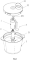
- a food kneading appliance includes a container 3, a central body 1 located on the center of the container 3, two kneading tools 2 located on the central body 1, and a drive unit for driving the central body 1.
- the central body 1 includes a stirring spindle 11 and a kneading spindle 12 which is configured on the stirring spindle 11.
- the stirring spindle 11 and the kneading spindle 12 are located in the same axis and rotating in opposite directions in operation.
- the kneading tools 2 include a dough hook 21 disposed on the stirring spindle 11 and a dough mixer 23 disposed on the kneading spindle 12.
- the dough hook 21 is substantially J shaped, one end of the dough hook 21 extends downwardly from a lower side of the stirring spindle 11, and then extends upwardly after bending angularly.
- a substantially inverted L-shape kneading arm 22 is mounted on the outside of the upper kneading spindle 14.
- the dough mixer 23 is connected to the free end of the kneading arm 22 and is formed as paddle shape.
- the dough hook 21 can protrude substantially horizontally from the lower part of the stirring spindle 11 and extends upwardly after bending angularly.
- the drive unit includes a drive shaft 4 for driving the stirring spindle 11, and a motor for driving the drive shaft 4.
- a hollow cylindrical object 31 with both ends open is projected upward from the center of the bottom of the container 3.
- the cylindrical object 31 and the container 3 are molded in one.
- the central body 1 detachably sleeved on the outside of the cylindrical object 31.
- the drive shaft 4 connects to the stirring spindle 11 though the center of the cylindrical object 31.
- a driving bevel gear 111 is located on the upper inner side of the stirring spindle 11 and rotates along with the drive shaft 4 in operation.
- the kneading spindle 12 includes a lower kneading spindle 13 with an end connected to the stirring spindle 11, an upper kneading spindle 14, and a connector 15 connected to the other end of the lower kneading spindle 13 via a through hole defined in the center of the upper kneading spindle 14.
- the lower kneading spindle 13 defines several gear brackets 131. Several planet bevel gears 132 are received in the corresponding gear brackets, and can rotate freely in the gear brackets 131.
- the upper kneading spindle 14 has a following bevel gear 141 located inside of the lower portion.
- the driving bevel gear 111 drives the following bevel gear 141 rotating in counter direction via the planet bevel gears 132. That is ,the dough hook 21 and the dough mixer 23 also rotate in opposite direction. Preferably, the dough hook 21 and the dough mixer 23 rotate in different circles.
- the container 3 includes a cover 32 and the cover includes a feeding passage 33.
- the lower kneading spindle 13 is connected with the connector 15 by screw joints which are respectively set in the lower inside part of the connector 15 and in the upper outside part of the lower kneading spindle 13, a locker groove on the connector 15 is used to lock a holder 321 which is fixedly connected to the cover 32.
- the kneading spindle 12 includes the lower kneading spindle 13 configured in bottom, and the upper kneading spindle 14 configured in the middle, and the connector 15 configured on top.
- the inner walls of both the lower kneading spindle 13 and the stirring spindle 11 having multiple guide rails and corresponding guide grooves which are matching each other for strength the fixation. And depending on the multiple guide rails and guide grooves, the upper portion of the stirring spindle 11 does not shake when it rotates.
- planet bevel gears 132 fixed on the gear brackets 131 which are configured in the side of the axis of the lower kneading spindle 13, the planet bevel gears 132 are allowed to rotate freely in the gear brackets 131 but can't be moved axially.
- the several planet bevel gears 132 are engaged between the driving bevel gear 111 and the following bevel gear 141.
- the driving bevel gear 111 is driven by motor and transmit power to the following bevel gear 141 and to rotate the upper kneading spindle 14 in counter rotation, the lower kneading spindle 13 and the connector 15 will not rotate.
- the gear unit includes the several planet bevel gears 132, the driving bevel gear 111 and the following bevel gear 141.
- the kneading arm 22 extends a part horizontally outside the upper kneading spindle 14, and then extending angularly downward, the dough mixer 23 is formed with the kneading arm 22.
- the angle of the kneading arm 22 bending is 90°in the Embodiment I.
- the dough mixer 23 is designed as paddle shape, it can increase contact area between the dough mixer 23 and dough.
- the lower kneading spindle 13 is connected with the connector 15 by screw joints 133, 151 which are respectively set in the lower inside part of the connector 15 and in the upper outside part of the lower kneading spindle 13, a locker groove on the connector 15 is used to lock the holder 321.
- the stirring spindle 11 is driven by the drive shaft 4 directly, the upper kneading spindle 14 driven by the gear unit are opposite on rotation direction, so that the dough hook 21 and the dough mixer 23 are different in rotation direction, the speed ratio is 1:1.
- Setting two kneading tools up and down and on counter rotation is to imitate the state of hand-making and to reach hand-making effect.
- the motor of driven unit is controlled by the control unit to achieve the speed adjusting and the positive and negative rotation. It can be driven directly by motor or indirectly by the gear unit.
- the Embodiment I is to achieve low speed rotation through speed switch by transmission, to avoid the case of overheat and deterioration in dough and to avoid the noise from severe vibration.
- the kneading tools formed up and down and rotated in different direction can increase touching times between dough and kneading tools. Comparing that with single dough hook and this with two kneading tools on the same speed, latter relative speed of dough and kneading tool is larger several times than the former, and kneading is better in consistency, gluten development and texture, and be allowed to reach manual kneading effect, meanwhile, the latter can restrain severe vibration and sway due to unbalance by single dough hook.
- the driving bevel gear 111 is allowed to set more planet bevel gears, so that the bearing capacity will be stronger, and processing more dough in one round.
- Embodiment II is similar to Embodiment I on structure, but be different from the shape of the dough mixer 23 which is L-style, and there is no need to set kneading arm.
- the L-shape dough mixer's 23 horizontal length and bending and vertical length are allowed to be various on design.
- the drive shaft 4 driven by drive unit and rotate the central body 1 and the kneading tools 2, because of the gear unit, the dough hook 21 and the dough mixer 23 will rotate in different direction, to stir and knead water and flour.
- the dough begin to be more sticky
- the central body 1 takes part in the kneading with the inner wall of the container 3 to squeeze the dough
- the dough hook 21 is extending under the dough and cause the dough move.
- the dough mixer 23 can achieve beat, knead and other manual effect, the kneading tools 2 may be replaced by other structure that realize the similar or the same function.
- the invention can restrain the noise of appliance's severe vibration effectively, also, the appliance will not sway.
- the central body 1 and the kneading tools 2 can be removed from the container and cleaned, both of them can be made of non-sticky metal or plastic in order to facilitate ease of cleaning.
- the appliance can provide large torque and low speed operation so that the dough can be processed without overheating and deteriorating. Beyond that, the dough is easy to be thoroughly mixed and achieve high quality dough that is comparable to manual kneading.
- Another advantage of the invention is that the kneading process is stable and low in noise. Vibration and sway will be avoided due to the balancing force of counterrotation action of the two kneading tools.
- the appliance has the advantages of strong bearing capacity in a single kneading, with stable function and being clever to drive various of kneading tools, it's easy to be cleaned, to provide simple and reliable structure.
Landscapes
- Engineering & Computer Science (AREA)
- Food Science & Technology (AREA)
- Life Sciences & Earth Sciences (AREA)
- Mechanical Engineering (AREA)
- Chemical & Material Sciences (AREA)
- Chemical Kinetics & Catalysis (AREA)
- Food-Manufacturing Devices (AREA)
- Manufacturing And Processing Devices For Dough (AREA)
Claims (8)
- - Nahrungsmittelknetgerät, umfassend:einen Behälter (3);einen zentralen Körper (1), der sich auf einem zentralen Teil des Behälters (3) befindet;mindestens zwei Knetwerkzeuge (2), die sich auf dem zentralen Körper (1) befinden; undeine Antriebseinheit, um den zentralen Körper (1) anzutreiben;der zentrale Körper (1) umfasst eine Rührspindel (11) und eine Knetspindel (12), die auf der Rührspindel (11) konfiguriert ist, die Rührspindel (11) und die Knetspindel (12) befinden sich in der gleichen Achse und drehen sich im Betrieb in entgegengesetzte Richtungen, die Knetwerkzeuge (2) umfassen mindestens einen Teighaken (21), der auf der Rührspindel (11) angeordnet ist, und einen Teigmischer (23), der auf der Knetspindel (12) angeordnet ist;die Knetspindel (12) beinhaltet eine untere Knetspindel (13), die im Boden konfiguriert ist, eine obere Knetspindel (14), die in der Mitte konfiguriert ist, und einen Verbinder (15), der auf der oberen Seite konfiguriert ist;eine äußere Seite der oberen Knetspindel (14) ist mit einem im Wesentlichen umgekehrten L-förmigen Knetarm (22) montiert, dessen freies Ende mit dem Teigmischer (23) verbunden ist, der als Paddelform gebildet ist;das Nahrungsmittelknetgerät ist dadurch gekennzeichnet, dass:die untere Knetspindel (13) ein Ende aufweist, das mit der Rührspindel (11) verbunden ist, und ein anderes Ende, das mit dem Verbinder (15) über ein Durchgangsloch verbunden ist, das in einem zentralen Teil der oberen Knetspindel (14) definiert ist; durch das Durchgangsloch, das im zentralen Teil der oberen Knetspindel (14) definiert ist, ist die untere Knetspindel (3) mit dem Verbinder (15) durch Schraubverbindungen verbunden, die jeweils in einem unteren inneren Teil des Verbinders (15) und in einem oberen äußeren Seitenteil der unteren Knetspindel (13) angeordnet sind; undeine Verriegelungsnut auf dem Verbinder (15) ist mit einer Haltevorrichtung (321) verriegelt, die fest mit einer Abdeckung (32) des Behälters (3) verbunden ist.
- - Nahrungsmittelknetgerät nach Anspruch 1, wobei sich die Knetspindel (12) auf einem oberen Abschnitt der Rührspindel (11) befindet.
- - Nahrungsmittelknetgerät nach Anspruch 1, wobei die Antriebseinheit eine Antriebswelle (4) umfasst, um die Rührspindel (11) anzutreiben, und einen Motor, um die Antriebswelle (4) anzutreiben; sich ein Antriebskegelrad (111) auf einer oberen inneren Seite der Rührspindel (11); befindet; die obere Knetspindel (14) ein folgendes Kegelrad (141) aufweist, das sich innerhalb des unteren Abschnitts befindet, und die untere Knetspindel (13) mit mehreren Getriebeklammern (131) ausgestattet ist, mehrere Planetenkegelräder (132) in den Getriebeklammern (131) aufgenommen und frei in den Getriebeklammern (131) drehbar sind; das Antriebskegelrad (111) das folgende Kegelrad (141), das sich in einer entgegengesetzten Richtung dreht, über die Planetenkegelräder (132) antreibt.
- - Nahrungsmittelknetgerät nach Anspruch 3, wobei ein hohler zylindrischer Gegenstand (31), dessen beide Enden geöffnet sind, von einem Zentrum eines Bodenteils des Behälters (3) nach außen vorspringt; der zentrale Körper (1) abnehmbar auf einer Außenseite des zylindrischen Gegenstands (31) montiert ist, die Antriebswelle (4) mit dem zentralen Körper (1) durch ein Zentrum des zylindrischen Gegenstands (31) verbunden ist.
- - Nahrungsmittelknetgerät nach Anspruch 4, wobei die Abdeckung (32) des Behälters (3) einen Zufuhrdurchgang (33) umfasst.
- - Nahrungsmittelknetgerät nach Anspruch 4, wobei der zylindrische Gegenstand (31) und der Behälter (3) ineinander geformt sind.
- - Nahrungsmittelknetgerät nach Anspruch 1, wobei der Teighaken (21) im Wesentlichen J-förmig ist, sich ein Ende des Teighakens (21) nach unten von einer unteren Seite der Rührspindel (11) erstreckt und sich dann nach oben erstreckt, nachdem er sich im Winkel biegt; der Knetarm (22), montiert auf die äußere Seite der oberen Knetspindel (14), eine im Wesentlichen umgekehrte L-Form aufweist; der Teigmischer (23), verbunden mit dem freien Ende der Knetarms (22), als eine Paddelform gebildet ist.
- - Nahrungsmittelknetgerät nach Anspruch 1, wobei der Teighaken (21) im Wesentlichen horizontal von einem unteren Teil der Rührspindel (11) vorspringt und sich nach oben erstreckt, nachdem er sich im Winkel biegt, der Teigmischer (23), konfiguriert außerhalb der oberen Knetspindel (14), im Wesentlichen als eine L-Form gebildet ist.
Applications Claiming Priority (1)
| Application Number | Priority Date | Filing Date | Title |
|---|---|---|---|
| CN201320065741 | 2013-02-05 |
Publications (3)
| Publication Number | Publication Date |
|---|---|
| EP2762004A2 EP2762004A2 (de) | 2014-08-06 |
| EP2762004A3 EP2762004A3 (de) | 2014-10-15 |
| EP2762004B1 true EP2762004B1 (de) | 2022-03-02 |
Family
ID=48534180
Family Applications (1)
| Application Number | Title | Priority Date | Filing Date |
|---|---|---|---|
| EP13168946.5A Active EP2762004B1 (de) | 2013-02-05 | 2013-05-23 | Nahrungsmittelknetgerät |
Country Status (3)
| Country | Link |
|---|---|
| US (1) | US9420801B2 (de) |
| EP (1) | EP2762004B1 (de) |
| CN (1) | CN103202324B (de) |
Families Citing this family (13)
| Publication number | Priority date | Publication date | Assignee | Title |
|---|---|---|---|---|
| CN103202324B (zh) * | 2013-02-05 | 2015-04-15 | 惠阳亚伦塑胶电器实业有限公司 | 一种食品搓揉设备 |
| GB2548082A (en) * | 2016-02-24 | 2017-09-13 | Kenwood Ltd | Processing tool |
| CN106070403A (zh) * | 2016-07-18 | 2016-11-09 | 张楠 | 一种新型食品工厂用自动揉面装置 |
| CH712834A1 (de) * | 2016-08-26 | 2018-02-28 | Betty Bossi Ag | Teigmischgerät. |
| CN106135332B (zh) * | 2016-08-29 | 2019-01-29 | 江门市新会区浩信电器制造有限公司 | 一种揉面机 |
| CN107865014B (zh) * | 2016-09-27 | 2023-05-16 | 惠阳亚伦塑胶电器实业有限公司 | 一种双向搅面粉装置 |
| CN106665725A (zh) * | 2017-02-20 | 2017-05-17 | 刘魁 | 一种揉面效果好的面条机 |
| CN107020036A (zh) * | 2017-06-16 | 2017-08-08 | 郑笔耕 | 一种块状药材研磨混合装置 |
| CN208447339U (zh) * | 2017-06-26 | 2019-02-01 | 汪恩光 | 一种小型食材切碎搅拌机 |
| CN110292319B (zh) * | 2018-03-22 | 2021-12-21 | 佛山市顺德区美的电热电器制造有限公司 | 面包机 |
| CN109323949B (zh) * | 2018-11-30 | 2023-10-13 | 山东省食品药品检验研究院 | 一种方便面复水测定装置及其测定方法 |
| CN113493322B (zh) * | 2021-07-16 | 2023-07-25 | 河南省恒信阳光实业有限公司 | 一种油井水泥缓凝剂制备用混合机 |
| USD1057515S1 (en) * | 2022-12-19 | 2025-01-14 | Menachem Dangot | Collar for a mixer |
Family Cites Families (25)
| Publication number | Priority date | Publication date | Assignee | Title |
|---|---|---|---|---|
| DE53824C (de) * | 1890-01-22 | 1890-10-04 | Firma C. marget & ClE. in Zell, Wiesenthal | Trockenapparat mit verschiedener Drehrichtung der Transportschaufeln |
| FR421255A (fr) * | 1909-10-12 | 1911-02-18 | Horace Mann Cake | Dispositif pour la propulsion des navires |
| US1555043A (en) * | 1924-05-31 | 1925-09-29 | Wagner Alfred | Propeller |
| US1692022A (en) * | 1924-06-25 | 1928-11-20 | Babitzky Samuel | Mixing machine |
| GB686771A (en) * | 1950-01-24 | 1953-01-28 | E J Bowman London Ltd | Improvements in or relating to rotary mixing and like apparatus |
| US3054565A (en) * | 1955-08-12 | 1962-09-18 | Willems Peter | Kneading and mixing apparatus |
| US3176968A (en) * | 1956-06-28 | 1965-04-06 | Arthur I Appleton | Portable food mixer |
| US4049243A (en) * | 1976-07-19 | 1977-09-20 | Hyman Kramer | Blending and kneading apparatus |
| SU1180056A1 (ru) * | 1984-04-02 | 1985-09-23 | Ленинградский Ордена Октябрьской Революции И Ордена Трудового Красного Знамени Технологический Институт Им.Ленсовета | Перемешивающее устройство |
| SE8802879L (sv) * | 1988-08-12 | 1990-02-13 | Novlab Innovation Ab | Omroerare |
| DE4310847C2 (de) * | 1993-04-02 | 1996-04-11 | Braun Ag | Antriebseinrichtung für eine Küchenmaschine |
| JPH07121350B2 (ja) * | 1993-05-20 | 1995-12-25 | 康郎 三波 | 混練機 |
| FI974256L (fi) * | 1997-02-25 | 1998-08-26 | Jouko Viljo Kalervo Niemi | Differentiaali-monipotkurijärjestelmä |
| CN1179650C (zh) * | 2000-06-03 | 2004-12-15 | 布雷维尔有限公司 | 自动面包机 |
| DE60307493T2 (de) * | 2002-03-05 | 2007-09-13 | Sancassiano S.P.A., Roddi D'alba | Knetmaschine für Teigmittel, insbesondere für Backwaren |
| CN2560211Y (zh) * | 2002-07-26 | 2003-07-16 | 曾春海 | 双动和面机 |
| CN2680029Y (zh) * | 2004-01-02 | 2005-02-23 | 番禺嘉宏食品机械有限公司 | 搅拌机 |
| CN2800808Y (zh) * | 2005-06-24 | 2006-08-02 | 中国人民解放军总后勤部军需装备研究所 | 一种和面机 |
| CN201160461Y (zh) * | 2008-03-04 | 2008-12-10 | 高国民 | 小型面粉和揉机 |
| EP2145571A1 (de) | 2008-06-11 | 2010-01-20 | Koninklijke Philips Electronics N.V. | Knetvorrichtung zum Kneten von Inhaltsstoffen in einem Teig und Knetwerkzeug |
| CN201479809U (zh) * | 2008-09-05 | 2010-05-26 | 何权林 | 和面揉面机 |
| IT1399634B1 (it) * | 2010-04-26 | 2013-04-26 | G S G Srl | Macchina per il trattamento di miscele alimentari ad attivazione centralizzata |
| IT1401799B1 (it) * | 2010-09-29 | 2013-08-28 | Firex S R L | Macchina per miscelazione o taglio, particolarmente per la trasformazione di alimenti, agente con albero a movimento planetario |
| CN103202324B (zh) * | 2013-02-05 | 2015-04-15 | 惠阳亚伦塑胶电器实业有限公司 | 一种食品搓揉设备 |
| CN203693407U (zh) * | 2014-01-20 | 2014-07-09 | 深圳市牧人电器五金制品有限公司 | 一种揉面钩结构及应用其的揉面机 |
-
2013
- 2013-04-25 CN CN201310145710.9A patent/CN103202324B/zh active Active
- 2013-05-21 US US13/898,488 patent/US9420801B2/en active Active
- 2013-05-23 EP EP13168946.5A patent/EP2762004B1/de active Active
Also Published As
| Publication number | Publication date |
|---|---|
| EP2762004A3 (de) | 2014-10-15 |
| CN103202324B (zh) | 2015-04-15 |
| CN103202324A (zh) | 2013-07-17 |
| EP2762004A2 (de) | 2014-08-06 |
| US20140219045A1 (en) | 2014-08-07 |
| US9420801B2 (en) | 2016-08-23 |
Similar Documents
| Publication | Publication Date | Title |
|---|---|---|
| EP2762004B1 (de) | Nahrungsmittelknetgerät | |
| US4337000A (en) | Two-spindle planetary kitchen mixer-kneader and anti-climb dough hooks therefor | |
| KR101836790B1 (ko) | 재료를 반죽 덩어리로 반죽하기 위한 반죽 장치 및 반죽 공구 | |
| EP2916702B1 (de) | Mixer | |
| EP3264955A1 (de) | Mischvorrichtung und verfahren | |
| EP2981200A1 (de) | Mixergefäss, mixerbasiseinheit und mixer | |
| US20120014207A1 (en) | Electric appliance with dual speed output | |
| RU2475174C2 (ru) | Кухонный комбайн, инструментальная оснастка такого комбайна | |
| CN104602581B (zh) | 包括按照行星式运动被驱动的搅拌钩子的烹饪制备设备 | |
| CN104853659A (zh) | 食品搅拌装置 | |
| KR20130108877A (ko) | 착즙기용 반죽용기 | |
| CN111374574B (zh) | 包括具有角传动件的附件组件的烹饪制备家电系统以及用于其的附件组件和附件架 | |
| EP3089591B1 (de) | Rotor für teigknetmaschinen für lebensmittel und teigknetmaschine | |
| CN210330378U (zh) | 搅拌附件以及包括其的烹饪制备的家电设备 | |
| US10660341B2 (en) | Counter-rotating dough making mechanism | |
| JP2011120689A (ja) | 自動製パン機 | |
| CN220422917U (zh) | 一种多功能和面机 | |
| CN210987932U (zh) | 一种带有制作蛋清功能的新和面机 | |
| CN208195099U (zh) | 一种用于电子元件清洗机上的搅拌装置 | |
| RU2398378C2 (ru) | Устройство для непрерывного перемешивания пищевого теста, содержащее два сопряженных инструмента для перемешивания и боковой отвод | |
| JP3139114U (ja) | ケーキ生地用の撹拌羽根 | |
| CN211270273U (zh) | 一种出面率高的面食机 | |
| CN209348524U (zh) | 一种罐装食品搅拌机 | |
| CN214413943U (zh) | 搅拌桨结构以及多功能和面机 | |
| CN210019066U (zh) | 一种搅拌组件及搅拌机 |
Legal Events
| Date | Code | Title | Description |
|---|---|---|---|
| PUAI | Public reference made under article 153(3) epc to a published international application that has entered the european phase |
Free format text: ORIGINAL CODE: 0009012 |
|
| 17P | Request for examination filed |
Effective date: 20130523 |
|
| AK | Designated contracting states |
Kind code of ref document: A2 Designated state(s): AL AT BE BG CH CY CZ DE DK EE ES FI FR GB GR HR HU IE IS IT LI LT LU LV MC MK MT NL NO PL PT RO RS SE SI SK SM TR |
|
| AX | Request for extension of the european patent |
Extension state: BA ME |
|
| PUAL | Search report despatched |
Free format text: ORIGINAL CODE: 0009013 |
|
| AK | Designated contracting states |
Kind code of ref document: A3 Designated state(s): AL AT BE BG CH CY CZ DE DK EE ES FI FR GB GR HR HU IE IS IT LI LT LU LV MC MK MT NL NO PL PT RO RS SE SI SK SM TR |
|
| AX | Request for extension of the european patent |
Extension state: BA ME |
|
| RIC1 | Information provided on ipc code assigned before grant |
Ipc: B01F 7/16 20060101ALI20140908BHEP Ipc: A47J 43/046 20060101ALI20140908BHEP Ipc: A47J 43/08 20060101ALI20140908BHEP Ipc: A21C 1/02 20060101AFI20140908BHEP Ipc: A47J 43/07 20060101ALI20140908BHEP Ipc: A21C 1/14 20060101ALI20140908BHEP |
|
| R17P | Request for examination filed (corrected) |
Effective date: 20130625 |
|
| STAA | Information on the status of an ep patent application or granted ep patent |
Free format text: STATUS: REQUEST FOR EXAMINATION WAS MADE |
|
| STAA | Information on the status of an ep patent application or granted ep patent |
Free format text: STATUS: EXAMINATION IS IN PROGRESS |
|
| 17Q | First examination report despatched |
Effective date: 20200401 |
|
| GRAP | Despatch of communication of intention to grant a patent |
Free format text: ORIGINAL CODE: EPIDOSNIGR1 |
|
| STAA | Information on the status of an ep patent application or granted ep patent |
Free format text: STATUS: GRANT OF PATENT IS INTENDED |
|
| RIC1 | Information provided on ipc code assigned before grant |
Ipc: A47J 43/08 20060101ALI20210929BHEP Ipc: A47J 43/07 20060101ALI20210929BHEP Ipc: B01F 7/16 20060101ALI20210929BHEP Ipc: B01F 7/00 20060101ALI20210929BHEP Ipc: A21C 1/14 20060101ALI20210929BHEP Ipc: A21C 1/02 20060101AFI20210929BHEP |
|
| INTG | Intention to grant announced |
Effective date: 20211025 |
|
| GRAS | Grant fee paid |
Free format text: ORIGINAL CODE: EPIDOSNIGR3 |
|
| GRAA | (expected) grant |
Free format text: ORIGINAL CODE: 0009210 |
|
| STAA | Information on the status of an ep patent application or granted ep patent |
Free format text: STATUS: THE PATENT HAS BEEN GRANTED |
|
| AK | Designated contracting states |
Kind code of ref document: B1 Designated state(s): AL AT BE BG CH CY CZ DE DK EE ES FI FR GB GR HR HU IE IS IT LI LT LU LV MC MK MT NL NO PL PT RO RS SE SI SK SM TR |
|
| REG | Reference to a national code |
Ref country code: GB Ref legal event code: FG4D |
|
| REG | Reference to a national code |
Ref country code: CH Ref legal event code: EP Ref country code: AT Ref legal event code: REF Ref document number: 1471523 Country of ref document: AT Kind code of ref document: T Effective date: 20220315 |
|
| REG | Reference to a national code |
Ref country code: DE Ref legal event code: R096 Ref document number: 602013081009 Country of ref document: DE |
|
| REG | Reference to a national code |
Ref country code: IE Ref legal event code: FG4D |
|
| REG | Reference to a national code |
Ref country code: LT Ref legal event code: MG9D |
|
| REG | Reference to a national code |
Ref country code: NL Ref legal event code: MP Effective date: 20220302 |
|
| PG25 | Lapsed in a contracting state [announced via postgrant information from national office to epo] |
Ref country code: SE Free format text: LAPSE BECAUSE OF FAILURE TO SUBMIT A TRANSLATION OF THE DESCRIPTION OR TO PAY THE FEE WITHIN THE PRESCRIBED TIME-LIMIT Effective date: 20220302 Ref country code: RS Free format text: LAPSE BECAUSE OF FAILURE TO SUBMIT A TRANSLATION OF THE DESCRIPTION OR TO PAY THE FEE WITHIN THE PRESCRIBED TIME-LIMIT Effective date: 20220302 Ref country code: NO Free format text: LAPSE BECAUSE OF FAILURE TO SUBMIT A TRANSLATION OF THE DESCRIPTION OR TO PAY THE FEE WITHIN THE PRESCRIBED TIME-LIMIT Effective date: 20220602 Ref country code: LT Free format text: LAPSE BECAUSE OF FAILURE TO SUBMIT A TRANSLATION OF THE DESCRIPTION OR TO PAY THE FEE WITHIN THE PRESCRIBED TIME-LIMIT Effective date: 20220302 Ref country code: HR Free format text: LAPSE BECAUSE OF FAILURE TO SUBMIT A TRANSLATION OF THE DESCRIPTION OR TO PAY THE FEE WITHIN THE PRESCRIBED TIME-LIMIT Effective date: 20220302 Ref country code: ES Free format text: LAPSE BECAUSE OF FAILURE TO SUBMIT A TRANSLATION OF THE DESCRIPTION OR TO PAY THE FEE WITHIN THE PRESCRIBED TIME-LIMIT Effective date: 20220302 Ref country code: BG Free format text: LAPSE BECAUSE OF FAILURE TO SUBMIT A TRANSLATION OF THE DESCRIPTION OR TO PAY THE FEE WITHIN THE PRESCRIBED TIME-LIMIT Effective date: 20220602 |
|
| PGFP | Annual fee paid to national office [announced via postgrant information from national office to epo] |
Ref country code: GB Payment date: 20220428 Year of fee payment: 10 Ref country code: FR Payment date: 20220523 Year of fee payment: 10 |
|
| REG | Reference to a national code |
Ref country code: AT Ref legal event code: MK05 Ref document number: 1471523 Country of ref document: AT Kind code of ref document: T Effective date: 20220302 |
|
| PG25 | Lapsed in a contracting state [announced via postgrant information from national office to epo] |
Ref country code: PL Free format text: LAPSE BECAUSE OF FAILURE TO SUBMIT A TRANSLATION OF THE DESCRIPTION OR TO PAY THE FEE WITHIN THE PRESCRIBED TIME-LIMIT Effective date: 20220302 Ref country code: LV Free format text: LAPSE BECAUSE OF FAILURE TO SUBMIT A TRANSLATION OF THE DESCRIPTION OR TO PAY THE FEE WITHIN THE PRESCRIBED TIME-LIMIT Effective date: 20220302 Ref country code: GR Free format text: LAPSE BECAUSE OF FAILURE TO SUBMIT A TRANSLATION OF THE DESCRIPTION OR TO PAY THE FEE WITHIN THE PRESCRIBED TIME-LIMIT Effective date: 20220603 Ref country code: FI Free format text: LAPSE BECAUSE OF FAILURE TO SUBMIT A TRANSLATION OF THE DESCRIPTION OR TO PAY THE FEE WITHIN THE PRESCRIBED TIME-LIMIT Effective date: 20220302 |
|
| PG25 | Lapsed in a contracting state [announced via postgrant information from national office to epo] |
Ref country code: NL Free format text: LAPSE BECAUSE OF FAILURE TO SUBMIT A TRANSLATION OF THE DESCRIPTION OR TO PAY THE FEE WITHIN THE PRESCRIBED TIME-LIMIT Effective date: 20220302 |
|
| PG25 | Lapsed in a contracting state [announced via postgrant information from national office to epo] |
Ref country code: SM Free format text: LAPSE BECAUSE OF FAILURE TO SUBMIT A TRANSLATION OF THE DESCRIPTION OR TO PAY THE FEE WITHIN THE PRESCRIBED TIME-LIMIT Effective date: 20220302 Ref country code: SK Free format text: LAPSE BECAUSE OF FAILURE TO SUBMIT A TRANSLATION OF THE DESCRIPTION OR TO PAY THE FEE WITHIN THE PRESCRIBED TIME-LIMIT Effective date: 20220302 Ref country code: RO Free format text: LAPSE BECAUSE OF FAILURE TO SUBMIT A TRANSLATION OF THE DESCRIPTION OR TO PAY THE FEE WITHIN THE PRESCRIBED TIME-LIMIT Effective date: 20220302 Ref country code: PT Free format text: LAPSE BECAUSE OF FAILURE TO SUBMIT A TRANSLATION OF THE DESCRIPTION OR TO PAY THE FEE WITHIN THE PRESCRIBED TIME-LIMIT Effective date: 20220704 Ref country code: EE Free format text: LAPSE BECAUSE OF FAILURE TO SUBMIT A TRANSLATION OF THE DESCRIPTION OR TO PAY THE FEE WITHIN THE PRESCRIBED TIME-LIMIT Effective date: 20220302 Ref country code: CZ Free format text: LAPSE BECAUSE OF FAILURE TO SUBMIT A TRANSLATION OF THE DESCRIPTION OR TO PAY THE FEE WITHIN THE PRESCRIBED TIME-LIMIT Effective date: 20220302 Ref country code: AT Free format text: LAPSE BECAUSE OF FAILURE TO SUBMIT A TRANSLATION OF THE DESCRIPTION OR TO PAY THE FEE WITHIN THE PRESCRIBED TIME-LIMIT Effective date: 20220302 |
|
| PG25 | Lapsed in a contracting state [announced via postgrant information from national office to epo] |
Ref country code: IS Free format text: LAPSE BECAUSE OF FAILURE TO SUBMIT A TRANSLATION OF THE DESCRIPTION OR TO PAY THE FEE WITHIN THE PRESCRIBED TIME-LIMIT Effective date: 20220702 Ref country code: AL Free format text: LAPSE BECAUSE OF FAILURE TO SUBMIT A TRANSLATION OF THE DESCRIPTION OR TO PAY THE FEE WITHIN THE PRESCRIBED TIME-LIMIT Effective date: 20220302 |
|
| REG | Reference to a national code |
Ref country code: DE Ref legal event code: R097 Ref document number: 602013081009 Country of ref document: DE |
|
| REG | Reference to a national code |
Ref country code: CH Ref legal event code: PL |
|
| PLBE | No opposition filed within time limit |
Free format text: ORIGINAL CODE: 0009261 |
|
| STAA | Information on the status of an ep patent application or granted ep patent |
Free format text: STATUS: NO OPPOSITION FILED WITHIN TIME LIMIT |
|
| REG | Reference to a national code |
Ref country code: BE Ref legal event code: MM Effective date: 20220531 |
|
| PG25 | Lapsed in a contracting state [announced via postgrant information from national office to epo] |
Ref country code: MC Free format text: LAPSE BECAUSE OF FAILURE TO SUBMIT A TRANSLATION OF THE DESCRIPTION OR TO PAY THE FEE WITHIN THE PRESCRIBED TIME-LIMIT Effective date: 20220302 Ref country code: LU Free format text: LAPSE BECAUSE OF NON-PAYMENT OF DUE FEES Effective date: 20220523 Ref country code: LI Free format text: LAPSE BECAUSE OF NON-PAYMENT OF DUE FEES Effective date: 20220531 Ref country code: DK Free format text: LAPSE BECAUSE OF FAILURE TO SUBMIT A TRANSLATION OF THE DESCRIPTION OR TO PAY THE FEE WITHIN THE PRESCRIBED TIME-LIMIT Effective date: 20220302 Ref country code: CH Free format text: LAPSE BECAUSE OF NON-PAYMENT OF DUE FEES Effective date: 20220531 |
|
| 26N | No opposition filed |
Effective date: 20221205 |
|
| PG25 | Lapsed in a contracting state [announced via postgrant information from national office to epo] |
Ref country code: SI Free format text: LAPSE BECAUSE OF FAILURE TO SUBMIT A TRANSLATION OF THE DESCRIPTION OR TO PAY THE FEE WITHIN THE PRESCRIBED TIME-LIMIT Effective date: 20220302 |
|
| PG25 | Lapsed in a contracting state [announced via postgrant information from national office to epo] |
Ref country code: IE Free format text: LAPSE BECAUSE OF NON-PAYMENT OF DUE FEES Effective date: 20220523 |
|
| PG25 | Lapsed in a contracting state [announced via postgrant information from national office to epo] |
Ref country code: BE Free format text: LAPSE BECAUSE OF NON-PAYMENT OF DUE FEES Effective date: 20220531 |
|
| PG25 | Lapsed in a contracting state [announced via postgrant information from national office to epo] |
Ref country code: IT Free format text: LAPSE BECAUSE OF FAILURE TO SUBMIT A TRANSLATION OF THE DESCRIPTION OR TO PAY THE FEE WITHIN THE PRESCRIBED TIME-LIMIT Effective date: 20220302 |
|
| GBPC | Gb: european patent ceased through non-payment of renewal fee |
Effective date: 20230523 |
|
| PG25 | Lapsed in a contracting state [announced via postgrant information from national office to epo] |
Ref country code: HU Free format text: LAPSE BECAUSE OF FAILURE TO SUBMIT A TRANSLATION OF THE DESCRIPTION OR TO PAY THE FEE WITHIN THE PRESCRIBED TIME-LIMIT; INVALID AB INITIO Effective date: 20130523 |
|
| PG25 | Lapsed in a contracting state [announced via postgrant information from national office to epo] |
Ref country code: MK Free format text: LAPSE BECAUSE OF FAILURE TO SUBMIT A TRANSLATION OF THE DESCRIPTION OR TO PAY THE FEE WITHIN THE PRESCRIBED TIME-LIMIT Effective date: 20220302 Ref country code: CY Free format text: LAPSE BECAUSE OF FAILURE TO SUBMIT A TRANSLATION OF THE DESCRIPTION OR TO PAY THE FEE WITHIN THE PRESCRIBED TIME-LIMIT Effective date: 20220302 Ref country code: GB Free format text: LAPSE BECAUSE OF NON-PAYMENT OF DUE FEES Effective date: 20230523 |
|
| PG25 | Lapsed in a contracting state [announced via postgrant information from national office to epo] |
Ref country code: FR Free format text: LAPSE BECAUSE OF NON-PAYMENT OF DUE FEES Effective date: 20230531 |
|
| PG25 | Lapsed in a contracting state [announced via postgrant information from national office to epo] |
Ref country code: TR Free format text: LAPSE BECAUSE OF FAILURE TO SUBMIT A TRANSLATION OF THE DESCRIPTION OR TO PAY THE FEE WITHIN THE PRESCRIBED TIME-LIMIT Effective date: 20220302 |
|
| PG25 | Lapsed in a contracting state [announced via postgrant information from national office to epo] |
Ref country code: MT Free format text: LAPSE BECAUSE OF FAILURE TO SUBMIT A TRANSLATION OF THE DESCRIPTION OR TO PAY THE FEE WITHIN THE PRESCRIBED TIME-LIMIT Effective date: 20220302 |
|
| PGFP | Annual fee paid to national office [announced via postgrant information from national office to epo] |
Ref country code: DE Payment date: 20250428 Year of fee payment: 13 |