EP2752539B2 - Treibriegelschloss - Google Patents
Treibriegelschloss Download PDFInfo
- Publication number
- EP2752539B2 EP2752539B2 EP13150413.6A EP13150413A EP2752539B2 EP 2752539 B2 EP2752539 B2 EP 2752539B2 EP 13150413 A EP13150413 A EP 13150413A EP 2752539 B2 EP2752539 B2 EP 2752539B2
- Authority
- EP
- European Patent Office
- Prior art keywords
- ejector
- lock
- adapter
- bolt
- drive rod
- Prior art date
- Legal status (The legal status is an assumption and is not a legal conclusion. Google has not performed a legal analysis and makes no representation as to the accuracy of the status listed.)
- Active
Links
- 238000009434 installation Methods 0.000 description 3
- 238000005299 abrasion Methods 0.000 description 1
- 238000004049 embossing Methods 0.000 description 1
- 238000009413 insulation Methods 0.000 description 1
- 125000006850 spacer group Chemical group 0.000 description 1
Images

Classifications
-
- E—FIXED CONSTRUCTIONS
- E05—LOCKS; KEYS; WINDOW OR DOOR FITTINGS; SAFES
- E05B—LOCKS; ACCESSORIES THEREFOR; HANDCUFFS
- E05B63/00—Locks or fastenings with special structural characteristics
- E05B63/06—Locks or fastenings with special structural characteristics with lengthwise-adjustable bolts ; with adjustable backset, i.e. distance from door edge
-
- E—FIXED CONSTRUCTIONS
- E05—LOCKS; KEYS; WINDOW OR DOOR FITTINGS; SAFES
- E05B—LOCKS; ACCESSORIES THEREFOR; HANDCUFFS
- E05B63/00—Locks or fastenings with special structural characteristics
- E05B63/24—Arrangements in which the fastening members which engage one another are mounted respectively on the wing and the frame and are both movable, e.g. for release by moving either of them
- E05B63/248—Arrangements in which the fastening members which engage one another are mounted respectively on the wing and the frame and are both movable, e.g. for release by moving either of them the striker being movable for latching, and pushed back by a member on the wing for unlatching, or vice versa
-
- E—FIXED CONSTRUCTIONS
- E05—LOCKS; KEYS; WINDOW OR DOOR FITTINGS; SAFES
- E05C—BOLTS OR FASTENING DEVICES FOR WINGS, SPECIALLY FOR DOORS OR WINDOWS
- E05C7/00—Fastening devices specially adapted for two wings
- E05C7/04—Fastening devices specially adapted for two wings for wings which abut when closed
-
- E—FIXED CONSTRUCTIONS
- E05—LOCKS; KEYS; WINDOW OR DOOR FITTINGS; SAFES
- E05B—LOCKS; ACCESSORIES THEREFOR; HANDCUFFS
- E05B65/00—Locks or fastenings for special use
- E05B65/10—Locks or fastenings for special use for panic or emergency doors
Definitions
- the invention relates to a drive bolt lock for a door having a moving leaf, with a latch ejector and a latch ejector drive.
- a preferred escape door solution for double-leaf doors usually uses active leaf and passive leaf locking systems.
- the active leaf has locks with at least one latch. If necessary, these locks can also be provided with a bolt.
- the passive leaf is locked by means of one or two drive rods, which engage in the lintel or crossbeam of the frame and, if necessary, in the floor.
- so-called drive bolt locks are used on the passive leaf side.
- a mortise lock with a variable backset and variable lock bolt length is known.
- the latch consists of two parts, a basic latch and an element to be attached.
- the DE 29 12 881 A1 discloses an espagnolette lock with a length-adjustable trap known. However, this has the disadvantage that it requires a lot of installation space in the lock case.
- a panic door lock for double-leaf doors is known, in which the latch and switch bolt can be inserted into the panic lock by means of cross slides so that the active leaf can be opened. It is not possible to adapt the lock mechanism.
- US 6,409,231 B1 A locking mechanism is shown in which adjustable locking bolts are connected to one another via a lever mechanism, so that when the active leaf is closed, the passive leaf is locked to the door frame.
- the FR 2 795 120 A1 shows a mortise lock with a latch, which has a detachable head piece, so that the latch length is adjustable with spacers.
- the object of the invention is to provide a drive bolt lock in which it can be ensured that the ejectors are extended sufficiently far from the lock case.
- the adapter that can be placed on the latch ejector offers the main advantage that the drive bolt lock can be used both without and with an adapter and that the adapter can be used to quickly or easily compensate or bridge a gap between the active leaf and the passive leaf that is too large.
- the adapter can be retrofitted to the ejector. Using the adapter, the extended length of the ejector can be set so that the latch is ejected with certainty on the one hand, but on the other hand the ejector does not protrude beyond the driving bolt lock so that it collides with the opposite active leaf lock.
- the drive bolt lock has a bolt ejector and a bolt ejector drive, the end face of the bolt ejector being extendable, in particular an adapter being attachable to it.
- the solution according to the invention is also applied to the bolt ejector.
- the adapter is detachably connected to the ejector so that the drive bolt lock can be adjusted not only once but also after installation in the sash if necessary.
- the adapter can also be removed if necessary.
- the adapter can be easily attached or removed by screwing the adapter to the ejector.
- the screw penetrates the adapter and is screwed into the ejector at the front.
- the adapter is positively connected to the ejector. This ensures, on the one hand, that a loosely attached adapter does not cause rattling noises, and the movements and forces of the ejector are transmitted undamped.
- the invention provides that the positive connection is formed by a mortise, that is, a tenon and a tenon receptacle.
- the adapter is designed as a plate and the pin and the pin receptacle are molded into the plate by means of an embossing.
- Another embodiment not according to the invention provides that the positive connection of one Dovetail connection is formed.
- tensile and compressive forces can be transmitted if necessary.
- the front side of the ejector is designed as a functional surface which ejects the latch or a bolt.
- the free end face of the adapter is designed as a functional surface which ejects the latch or a bolt.
- the adapter can be fastened axially to the end face of the ejector without opening the housing of the drive bolt lock. It can then be a or several adapters are placed axially on the end face of the ejector.
- a door, generally designated 10, which has a passive leaf 12 and an active leaf 14. Both the passive leaf 12 and the active leaf 14 are pivotally connected to a frame 18 via hinges 16.
- the active leaf 14 can be locked with the passive leaf 12 via a lock 20 and the passive leaf 12 has a drive bolt lock 22, to which an upper drive rod 24 and a lower drive rod 26 are coupled.
- the lower drive rod 26 engages with its downward free end 28 in the ground and the upper drive rod 24 engages with its upward free end 30 in the lintel or crossbar 32 of the frame 18.
- the lock 20 and the driving bolt lock 22 lie opposite one another, so that the latch of the lock 20 engages in the driving bolt lock 22.
- the bolt of the lock 20 also engages in the driving bolt lock 22.
- the two wings 12 and 14 are set on their hinges 16 such that they take up a defined gap dimension 34 between them.
- the latch ejectors 40 and latch ejectors 42 do not protrude so far from the driving bolt lock 22 that they collide with the active leaf lock 20.
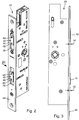
- the Figure 2 shows the drive bolt lock 22 in a perspective view and the ejected latch ejectors 40 and bolt ejectors 42 can be seen.
- the end faces 44 and 46 of the two ejectors 40 and 42 press the latch and the bolt out of the driving bolt lock 22 if necessary.
- the two end sides 44 and 46 protrude from the driving bolt lock 22 so far that they have the cuff 48 on which the driving bolt lock 22 is screwed, protrude.
- the Figure 3 shows these two projections 50 and 52, the latch ejector 40 projecting less far than the bolt ejector 42.
- a rotation-proof fixation of the adapters 54 on the end faces 44 and 46 of the ejectors 40 and 42 is achieved via a positive connection with these end faces 44 and 46.
- the adapters 54 are provided with a pin and a pin receptacle 62 receiving the pin.
- the end faces 44 and 46 of the ejectors 40 and 42 each have a pin receptacle 62, so that the pin projecting in the direction of the ejectors 40 and 42 can be received by these pin receptacles 62.
- the pin and the pin receptacle 62 are stamped into the plate-shaped adapter 54.
- the projections 50 and 52 are enlarged, the projection 52 being enlarged further than the projection 50.
- the adapters 54 can be attached without any problems without having to open the housing of the drive bolt lock 22.
Landscapes
- Engineering & Computer Science (AREA)
- Structural Engineering (AREA)
- Mechanical Engineering (AREA)
- Physics & Mathematics (AREA)
- Electromagnetism (AREA)
- Jet Pumps And Other Pumps (AREA)
- Lock And Its Accessories (AREA)
Description
- Die Erfindung betrifft ein Treibriegelschloss für eine einen Gangflügel aufweisende Tür, mit einem Fallenauswerfer und einem Fallenauswerferantrieb.
- Bei einer bevorzugten Fluchttürlösung für zweiflügelige Türen kommen üblicherweise Gangflügel- und Standflügelverschlusssysteme zum Einsatz. Dabei weisen die Gangflügel Schlösser mit zumindest einer Falle auf. Gegebenenfalls können diese Schlösser auch mit einem Riegel versehen sein. Der Standflügel wird mittels einer oder mit zwei Treibstangen verriegelt, die in den Sturz oder Querbalken des Rahmens und gegebenenfalls in den Boden eingreifen. Um das Schloss des Gangflügels im Bedarfsfall ohne direkte Betätigung des Schlosses öffnen zu können, werden auf der Standflügelseite sogenannte Treibriegelschlösser verwendet. Bei einer Panikbetätigung des Standflügelschlosses werden die obere und die untere Treibriegelstange eingezogen und gleichzeitig werden über Auslöseschieber oder Auswerfer die Falle und der Riegel des Gangflügelschlosses in den Schlosskasten zurückgedrückt, so dass das Türsystem geöffnet werden kann.
- Bei derartigen Türsystemen mit einem Gangflügel und einem Standflügel besteht die Anforderung, dass sie so in den Rahmen eingepasst sind, dass definierte Spaltmaße eingehalten werden, so dass die Flügel bewegt werden können, ohne dass sie am Boden oder an der Decke streifen. Sie müssen aber auch so schließen, dass die Falle und gegebenenfalls der Riegel des Gangflügelschlosses exakt in die hierfür vorgesehenen Riegelaufnahmen des Standflügelschlosses, also des Treibriegelschlosses, eingreifen. Bei zu großen Spaltmaßen ist dies nicht mehr gewährleistet. Dies wird noch durch unterschiedliche Kombinationen von zweiflügeligen Türen, insbesondere deren Flügelbreite, der Bandauslage, der Türluft usw., erschwert. Dadurch ergebenden sich unterschiedlich große Auswerfervorstände des Fallenauswerfers und gegebenenfalls des Riegelauswerfers, um die Falle und gegebenenfalls den Riegel sicher in das Gangflügelschloss zurückzuschieben und trotzdem ein reibungsloses Öffnen der beiden Türflügel zu gewährleisten.
- Aus der
DE 35 40 848 A1 ist ein Einsteckschloss mit einem variablen Dornmaß und variabler Schlossriegellänge bekannt. Um die Riegellänge nach dem Einbau des Schlosses exakt anpassen und auch später noch ändern zu können, wird vorgeschlagen, nach Art eines Bausteinsystems einen Basisriegel vorzusehen und einzelne Riegelelemente auf den Basisriegel aufzusetzen und aneinanderzukoppeln. Der Riegel besteht also aus zwei Teilen, einem Basisriegel und einem aufzusetzenden Element. - Die
DE 29 12 881 A1 offenbart einen Treibstangenverschluss mit einer in der Länge einstellbaren Falle bekannt. Diese hat jedoch den Nachteil, da sie viel Bauraum im Schlosskasten benötigt. - Aus der
DE 36 36 236 A1 ist ein Paniktürverschluss für zweiflügelige Türen bekannt, bei dem mittels Querschiebern Falle und Schaltriegel in das Panikschloss eingeschoben werden können, so dass der Gangflügel geöffnet werden kann. Eine Anpassung der Schlossmechanik ist nicht möglich. - In
US 6,409,231 B1 ist ein Riegelmechanismus gezeigt, bei dem einstellbare Schließriegel über eine Hebelmechanik miteinander verbunden sind, so dass beim Schließen des Gangflügels der Standflügel am Türrahmen verriegelt ist. DieFR 2 795 120 A1 - Der Erfindung liegt die Aufgabe zugrunde, ein Treibriegelschloss bereit zu stellen, bei dem sichergestellt werden kann, dass die Auswerfer ausreichend weit aus dem Schlosskasten ausgefahren werden.
- Diese Aufgabe wird bei einem Treibriegelschloss der eingangs genannten Art erfindungsgemäß dadurch gelöst, dass die Stirnseite des Fallenauswerfers verlängerbar, insbesondere auf diese ein Adapter aufsetzbar ist.
- Der auf den Fallenauswerfer aufsetzbare Adapter bietet den wesentlichen Vorteil, dass das Treibriegelschloss sowohl ohne als auch mit Adapter verwendbar ist und mittels des Adapters ein zu großer Spalt zwischen dem Gangflügel und dem Standflügel schnell und einfach ausgeglichen bzw. überbrückt werden kann. Der Adapter kann nachträglich auf den Auswerfer aufgesetzt werden. Mittels des Adapters kann die ausgefahrene Länge des Auswerfers so eingestellt werden, dass einerseits die Falle mit Bestimmtheit ausgeworfen wird, andererseits der Auswerfer aber auch nicht so weit über das Treibriegelschloss vorsteht, dass er mit dem gegenüber liegenden Gangflügelschloss kollidiert.
- Bei einer Weiterbildung der Erfindung weist das Treibriegelschloss einen Riegelauswerfer und einen Riegelauswerferantrieb auf, wobei die Stirnseite des Riegelauswerfers verlängerbar, insbesondere auf diese ein Adapter aufsetzbar ist. Somit wird die erfindungsgemäße Lösung auch beim Riegelauswerfer angewendet.
- Um das Treibriegelschloss nicht nur einmalig sondern auch nach dem Einbau in den Flügel im Bedarfsfall anpassen zu können, ist der Adapter lösbar mit dem Auswerfer verbunden.
- Ändert sich das Spaltmaß zwischen den Flügeln im Laufe der Zeit, z.B. durch Verzug der Flügel oder durch ein Setzen des Gebäudes, dann kann der Adapter gegebenenfalls auch wieder entfernt werden.
- Ein einfaches Befestigen bzw. Entfernen des Adapters wird dadurch erreicht, dass der Adapter mit dem Auswerfer verschraubt ist. Die Schraube durchsetzt dabei den Adapter und wird stirnseitig in den Auswerfer eingedreht.
- Gemäß der Erfindung ist der Adapter formschlüssig mit dem Auswerfer verbunden. Hierdurch ist einerseits gewährleistet, dass ein lose befestigter Adapter keine Klappergeräusche verursacht, außerdem werden die Bewegungen und Kräfte des Auswerfers ungedämpft übertragen.
- Die Erfindung sieht vor, dass der Formschluss von einer Verzapfung, also einem Zapfen und einer Zapfenaufnahme gebildet ist. Der Adapter ist als Platte ausgebildet und der Zapfen und die Zapfenaufnahme sind durch eine Prägung in die Platte eingeformt.
- Eine andere nicht erfindungsgemäße Ausführungsform sieht vor, dass der Formschluss von einer Schwalbenschwanzverbindung gebildet wird. Bei dieser Ausführungsform können, falls erforderlich, Zug- und Druckkräfte übertragen werden.
- Um größere Spaltmaße überbrücken zu können, können mehrere Adapter übereinander mit dem Auswerfer verbunden werden. Dabei sind dann alle Adapter ineinander gesteckt und werden mittels einer einzigen Schraube mit dem Auswerfer verschraubt.
- Die Stirnseite des Auswerfers ist als die Falle oder einen Riegel auswerfende Funktionsfläche ausgebildet. Außerdem ist die freie Stirnseite des Adapters als die Falle oder einen Riegel auswerfende Funktionsfläche ausgebildet. Dies bedeutet, dass der Auswerfer mit und ohne Adapter und der Adapter die gleichen Funktionen erfüllen kann und die gleichen Eigenschaften aufweist, wie der Auswerfer selbst, wie z.B. hohe Standfestigkeit, Abriebfestigkeit, eventuelle Geräuschdämmung, Einbruchsicherheit, Manipulationssicherheit usw..
- Um nach der Montage des Treibriegelschlosses dieses optimal an das Spaltmaß anpassen zu können, ist der Adapter ohne Öffnung des Gehäuses des Treibriegelschlosses axial an der Stirnfläche des Auswerfers befestigbar. Es können dann ein oder mehrere Adapter axial auf die Stirnfläche des Auswerfers aufgesetzt werden.
- Weitere Vorteile, Merkmale und Einzelheiten der Erfindung ergeben sich aus den Unteransprüchen sowie der nachfolgenden Beschreibung, in der unter Bezugnahme auf die Zeichnung ein besonders bevorzugtes Ausführungsbeispiel im Einzelnen beschrieben ist. Dabei können die in der Zeichnung dargestellten sowie in der Beschreibung und in den Ansprüchen erwähnten Merkmale jeweils einzeln für sich oder in beliebiger Kombination erfindungswesentlich sein.
- In der Zeichnung zeigen:
- Figur 1
- eine schematische Darstellung einer zweiflügeligen Tür mit einem Gang- und einem Standflügel;
- Figur 2
- eine perspektivische Ansicht eines Ausführungsbeispiels des erfindungsgemäßen Treibriegelschlosses, wobei die Auswerfer des Schlosses die ausgeschobene Stellung einnehmen;
- Figur 3
- eine Seitenansicht des Treibriegelschlosses in Richtung des Pfeils III gemäß
Figur 2 ; - Figur 4
- das Treibriegelschloss gemäß
Figur 2 mit auf die Auswerfer aufgesetzten Adaptern; und - Figur 5
- eine Seitenansicht des Treibriegelschlosses in Richtung des Pfeils V gemäß
Figur 4 . - In der
Figur 1 ist eine insgesamt mit 10 bezeichnete Tür dargestellt, die einen Standflügel 12 und einen Gangflügel 14 aufweist. Sowohl der Standflügel 12 als auch der Gangflügel 14 sind über Scharniere 16 mit einem Rahmen 18 schwenkbar verbunden. Der Gangflügel 14 ist über ein Schloss 20 mit dem Standflügel 12 verriegelbar und der Standflügel 12 weist ein Treibriegelschloss 22 auf, an welchem eine obere Treibstange 24 und eine untere Treibstange 26 angekoppelt sind. Die untere Treibstange 26 greift mit ihrem nach unten weisenden freien Ende 28 in den Boden und die obere Treibstange 24 greift mit ihrem nach oben weisenden freien Ende 30 in den Sturz oder Querbalken 32 des Rahmens 18 ein. Ferner ist erkennbar, dass das Schloss 20 und das Treibriegelschloss 22 einander gegenüberliegen, so dass die Falle des Schlosses 20 in das Treibriegelschloss 22 eingreift. Ebenso greift der Riegel des Schlosses 20 in das Treibriegelschloss 22 ein. Die beiden Flügel 12 und 14 sind an ihren Scharnieren 16 so eingestellt, dass sie zwischen sich ein definiertes Spaltmaß 34 einnehmen. Um eine sichere Verriegelung des Gangflügels 14 am Standflügel 12 zu gewährleisten muss sichergestellt sein, dass die Falle und der Riegel genügend weit in die entsprechenden Aufnahmen 36 und 38 (sieheFigur 2 ) des Treibriegelschlosses 22 eingreifen. Dabei muss aber auch berücksichtigt werden, dass die Falle und der Riegel sicher aus dem Treibriegelschloss 22 ausgeworfen werden, so dass der Gangflügel 14 reibungslos geöffnet werden kann. Ferner dürfen die die Fallen und den Riegel auswerfenden Fallenauswerfer 40 und Riegelauswerfer 42 (sieheFigur 2 ) nicht so weit aus dem Treibriegelschloss 22 vorstehen, dass sie mit dem gangflügelschloss 20 kollidieren. - Die
Figur 2 zeigt das Treibriegelschloss 22 in perspektivischer Ansicht und es sind die ausgeschobenen Fallenauswerfer 40 und Riegelauswerfer 42 erkennbar. Die Stirnseiten 44 und 46 der beiden Auswerfer 40 und 42 drücken die Falle und den Riegel bei Bedarf aus dem Treibriegelschloss 22. Dabei ragen die beiden Stirnseiten 44 und 46 so weit aus dem Treibriegelschloss 22 vor, dass sie die Stulpe 48, an welcher das Treibriegelschloss 22 angeschraubt ist, überragen. DieFigur 3 zeigt diese beiden Überstände 50 und 52, wobei der Fallenauswerfer 40 weniger weit vorsteht, als der Riegelauswerfer 42. - Besteht nun das Erfordernis, dass einer oder beide Überstände 50 und/oder 52 vergrößert werden muss, dann wird, wie in den
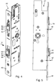
Figuren 4 und 5 dargestellt, auf die Stirnseiten 44 und 46 der beiden Auswerfer 40 und 42 ein oder es werden mehrere Adapter 54 aufgesetzt. Diese Adapter 54 besitzen eine eine Befestigungsschraube 56 aufnehmende Schrauböffnung 58. Die Befestigungsschraube 56 wird in in den Stirnseiten 44 und 46 der Auswerfer 40 und 42 vorgesehene Gewindebohrungen 60 (sieheFigur 2 ) eingeschraubt. - Eine verdrehsichere Fixierung der Adapter 54 an den Stirnseiten 44 und 46 der Auswerfer 40 und 42 wird über formschlüssige Verbindung mit diesen Stirnseiten 44 und 46 erreicht. Hierfür sind die Adapter 54 mit einem Zapfen und einer den Zapfen aufnehmenden Zapfenaufnahme 62 versehen. Auch die Stirnseiten 44 und 46 der Auswerfer 40 und 42 weisen jeweils eine Zapfenaufnahme 62 auf, so dass der in Richtung der Auswerfer 40 und 42 abragende Zapfen von diesen Zapfenaufnahmen 62 aufgenommen werden kann. Der Zapfen und die Zapfenaufnahme 62 sind in den plattenförmigen Adapter 54 eingeprägt.
- Wie aus den
Figuren 4 und 5 ersichtlich, sind die Überstände 50 und 52 vergrößert, wobei der Überstand 52 weiter vergrößert wurde, als der Überstand 50. Dies wurde dadurch ermöglicht, dass auf die Stirnseite 46 des Riegelauswerfers 42 nicht nur einer sondern zwei Adapter 54 aufgesetzt und angeschraubt wurden. Wie außerdem leicht erkennbar, können die Adapter 54 problemlos angebracht werden, ohne dass das Gehäuse des Treibriegelschlosses 22 geöffnet werden muss.
Claims (8)
- Treibriegelschloss (22) für eine einen Gangflügel (14) aufweisende Tür (10), mit einem Fallenauswerfer (40) und einem Fallenauswerferantrieb, wobei das Treibriegelschloss (22) einen Adapter (54) aufweist, der auf die Stirnseite (44) des Fallenauswerfers (40) aufsetzbar ist, so dass die Stirnseite (44) verlängerbar ist, wobei der Adapter (54) formschlüssig mit dem Auswerfer (40, 42) verbunden ist, dadurch gekennzeichnet, dass der Formschluss von einer Verzapfung mit einem Zapfen und einer Zapfenaufnahme (62) gebildet wird und dass der Adapter (54) eine Platte ist und der Zapfen und die Zapfenaufnahme (62) geprägt sind.
- Treibriegelschloss nach Anspruch 1, dadurch gekennzeichnet, dass ein Riegelauswerfer (42) und ein Riegelauswerferantrieb vorgesehen sind und dass das Treibriegelschloss (22) einen Adapter (54) aufweist, der auf die Stirnseite (46) des Riegelauswerfers (42) aufsetzbar ist, so dass die Stirnseite (46) verlängerbar ist.
- Treibriegelschloss nach einem der vorhergehenden Ansprüche, dadurch gekennzeichnet, dass der Adapter (54) lösbar mit dem Auswerfer (40, 42) verbunden ist.
- Treibriegelschloss nach einem der vorhergehenden Ansprüche, dadurch gekennzeichnet, dass der Adapter (54) mit dem Auswerfer (40, 42) verschraubt ist.
- Treibriegelschloss nach einem der vorhergehenden Ansprüche, dadurch gekennzeichnet, dass mehrere Adapter (54) übereinander mit dem Auswerfer (40, 42) verbunden sind.
- Treibriegelschloss nach einem der vorhergehenden Ansprüche, dadurch gekennzeichnet, dass die Stirnseite (44, 46) des Auswerfers (40, 42) als die Falle oder einen Riegel auswerfende Funktionsfläche ausgebildet ist.
- Treibriegelschloss nach einem der vorhergehenden Ansprüche, dadurch gekennzeichnet, dass die freie Stirnseite des Adapters (54) als die Falle oder einen Riegel auswerfende Funktionsfläche ausgebildet ist.
- Treibriegelschloss nach einem der vorhergehenden Ansprüche, dadurch gekennzeichnet, dass der Adapter (54) axial an der Stirnfläche (44, 46) des Auswerfers (40, 42) ohne Öffnung des Gehäuses des Treibriegelschlosses (22) befestigbar ist.
Priority Applications (1)
| Application Number | Priority Date | Filing Date | Title |
|---|---|---|---|
| EP13150413.6A EP2752539B2 (de) | 2013-01-07 | 2013-01-07 | Treibriegelschloss |
Applications Claiming Priority (1)
| Application Number | Priority Date | Filing Date | Title |
|---|---|---|---|
| EP13150413.6A EP2752539B2 (de) | 2013-01-07 | 2013-01-07 | Treibriegelschloss |
Publications (3)
| Publication Number | Publication Date |
|---|---|
| EP2752539A1 EP2752539A1 (de) | 2014-07-09 |
| EP2752539B1 EP2752539B1 (de) | 2017-08-02 |
| EP2752539B2 true EP2752539B2 (de) | 2020-03-25 |
Family
ID=47681632
Family Applications (1)
| Application Number | Title | Priority Date | Filing Date |
|---|---|---|---|
| EP13150413.6A Active EP2752539B2 (de) | 2013-01-07 | 2013-01-07 | Treibriegelschloss |
Country Status (1)
| Country | Link |
|---|---|
| EP (1) | EP2752539B2 (de) |
Cited By (2)
| Publication number | Priority date | Publication date | Assignee | Title |
|---|---|---|---|---|
| EP4512981A1 (de) | 2023-08-23 | 2025-02-26 | Carl Fuhr GmbH & Co. KG | Gegenkasten für einen standflügelverschluss |
| EP4575152A1 (de) | 2023-12-19 | 2025-06-25 | Carl Fuhr GmbH & Co. KG | Gegenkasten |
Families Citing this family (3)
| Publication number | Priority date | Publication date | Assignee | Title |
|---|---|---|---|---|
| DE102014118511A1 (de) | 2014-12-12 | 2016-06-16 | Eco Schulte Gmbh & Co. Kg | Fallenauswerfer mit einstellbarem Kontaktelement |
| DE102014225813A1 (de) | 2014-12-15 | 2016-06-16 | Aug. Winkhaus Gmbh & Co. Kg | Gegenschloss eines Treibstangenschlosses |
| DE102018115985B4 (de) | 2018-07-02 | 2021-12-09 | Assa Abloy Sicherheitstechnik Gmbh | Schlossgegenkasten für ein Aktivflügelschloss mit Falzluftausgleich |
Citations (2)
| Publication number | Priority date | Publication date | Assignee | Title |
|---|---|---|---|---|
| DE9211077U1 (de) † | 1992-08-18 | 1992-10-29 | BKS GmbH, 5620 Velbert | Panik-Treibstangenschloß |
| EP0688931A1 (de) † | 1994-06-21 | 1995-12-27 | BKS GmbH | Panik-Treibstangenschloss |
Family Cites Families (8)
| Publication number | Priority date | Publication date | Assignee | Title |
|---|---|---|---|---|
| DE273393C (de) * | ||||
| DE2912881A1 (de) | 1979-03-30 | 1980-10-09 | Scovill Sicherheitseinrichtung | Treibstangenverschluss, insbesondere fuer zweifluegelige feuerschutztueren |
| DE3540848A1 (de) | 1985-08-30 | 1987-03-12 | Eduard Schindler | Einsteckschloss mit variablem dornmass |
| DE3636236A1 (de) * | 1986-10-24 | 1988-04-28 | Betz Gmbh & Co Kg Geb | Panikverschluss fuer zweifluegelige tueren |
| FI104006B (fi) * | 1997-12-16 | 1999-10-29 | Abloy Oy | Oveen tai vastaavaan asennettava lukkorunko |
| FR2795120B1 (fr) | 1999-06-18 | 2005-09-23 | Metalux | Serrure a pene demi-tour reversible |
| US6409231B1 (en) * | 1999-09-30 | 2002-06-25 | Architectural Builders Hardware Manufacturing Inc. | Flush bolt mechanism |
| NZ529624A (en) * | 2003-11-18 | 2006-03-31 | Assa Abloy Financial Services | A multi-point lock |
-
2013
- 2013-01-07 EP EP13150413.6A patent/EP2752539B2/de active Active
Patent Citations (2)
| Publication number | Priority date | Publication date | Assignee | Title |
|---|---|---|---|---|
| DE9211077U1 (de) † | 1992-08-18 | 1992-10-29 | BKS GmbH, 5620 Velbert | Panik-Treibstangenschloß |
| EP0688931A1 (de) † | 1994-06-21 | 1995-12-27 | BKS GmbH | Panik-Treibstangenschloss |
Cited By (4)
| Publication number | Priority date | Publication date | Assignee | Title |
|---|---|---|---|---|
| EP4512981A1 (de) | 2023-08-23 | 2025-02-26 | Carl Fuhr GmbH & Co. KG | Gegenkasten für einen standflügelverschluss |
| DE102023122564A1 (de) | 2023-08-23 | 2025-02-27 | Carl Fuhr GmbH & Co. KG. | Gegenkasten für einen Standflügelverschluss |
| EP4575152A1 (de) | 2023-12-19 | 2025-06-25 | Carl Fuhr GmbH & Co. KG | Gegenkasten |
| DE102023135780A1 (de) * | 2023-12-19 | 2025-06-26 | Carl Fuhr GmbH & Co. KG. | Gegenkasten |
Also Published As
| Publication number | Publication date |
|---|---|
| EP2752539B1 (de) | 2017-08-02 |
| EP2752539A1 (de) | 2014-07-09 |
Similar Documents
| Publication | Publication Date | Title |
|---|---|---|
| EP2752539B2 (de) | Treibriegelschloss | |
| EP3798390B2 (de) | Faltanlage | |
| DE102015001960A1 (de) | Schliesszylinder mit zwei auf gleicher Achse beabstandet zueinander angeordneten Schliessnasen | |
| EP2113624B1 (de) | Tür- oder Fenstersicherungsvorrichtung | |
| EP3070238B1 (de) | Verriegelungsvorrichtung für eine tür oder ein fenster | |
| EP0433623A2 (de) | Verriegelungsvorrichtung für ein Fenster, eine Tür od.dgl. | |
| EP1172506B1 (de) | Schaltsperre für Mehrriegelverschlüsse | |
| DE102015211980B4 (de) | Verschlussvorrichtung für ein ein- oder mehrteiliges Tor | |
| WO2018046285A1 (de) | Aushebesicherung für einen verschiebbaren und zum verschieben anhebbaren flügel | |
| EP2466044B1 (de) | Schließeinrichtung | |
| EP1837460B1 (de) | Beschlag für einen Schiebeflügel sowie Beschlagsystem | |
| AT395630B (de) | Doppelfluegelige brandschutztuer | |
| DE102021115490B4 (de) | Feststellvorrichtung für beidseitig angeschlagene Tür | |
| DE102013203488A1 (de) | Öffnungsbegrenzer | |
| DE10015095C2 (de) | Verriegelungsvorrichtung für einen Türflügel | |
| EP1970513B1 (de) | Standflügel und Standflügelverschluss | |
| DE3417054A1 (de) | Treibstangenverschluss fuer den standfluegel von zweifluegeligen tueren, insbesondere selbsttaetig schliessenden feuerschutztueren | |
| DE202015001220U1 (de) | Schließzylinder mit zwei auf gleicher Achse beabstandet zueinander angeordneten Schließnasen | |
| EP2947241A1 (de) | Riegelschloss für ein türblatt einer tür sowie montageverfahren | |
| DE102014102041A1 (de) | Schließkantenklappe | |
| EP3626918B1 (de) | Beschlag für ein fenster, fenster | |
| EP0158069B1 (de) | Schliess- und Verriegelungsvorrichtung für eine Tür od. dgl. | |
| WO1993004253A1 (de) | Sicherheitstür und sicherheitsvorrichtung zum einbau in eine tür | |
| DE9421217U1 (de) | Schließeinrichtung mit mindestens einem zusätzlichen Sicherungsriegel | |
| EP4512981A1 (de) | Gegenkasten für einen standflügelverschluss |
Legal Events
| Date | Code | Title | Description |
|---|---|---|---|
| 17P | Request for examination filed |
Effective date: 20130107 |
|
| AK | Designated contracting states |
Kind code of ref document: A1 Designated state(s): AL AT BE BG CH CY CZ DE DK EE ES FI FR GB GR HR HU IE IS IT LI LT LU LV MC MK MT NL NO PL PT RO RS SE SI SK SM TR |
|
| AX | Request for extension of the european patent |
Extension state: BA ME |
|
| PUAI | Public reference made under article 153(3) epc to a published international application that has entered the european phase |
Free format text: ORIGINAL CODE: 0009012 |
|
| R17P | Request for examination filed (corrected) |
Effective date: 20141114 |
|
| RBV | Designated contracting states (corrected) |
Designated state(s): AL AT BE BG CH CY CZ DE DK EE ES FI FR GB GR HR HU IE IS IT LI LT LU LV MC MK MT NL NO PL PT RO RS SE SI SK SM TR |
|
| RIN1 | Information on inventor provided before grant (corrected) |
Inventor name: ROEHL CHRISTIAN Inventor name: VADALA JONATHAN Inventor name: HENNECKE GERHARD |
|
| RIC1 | Information provided on ipc code assigned before grant |
Ipc: E05B 65/10 20060101ALI20170117BHEP Ipc: E05B 63/06 20060101AFI20170117BHEP Ipc: E05C 7/04 20060101ALI20170117BHEP Ipc: E05B 63/24 20060101ALI20170117BHEP |
|
| GRAP | Despatch of communication of intention to grant a patent |
Free format text: ORIGINAL CODE: EPIDOSNIGR1 |
|
| INTG | Intention to grant announced |
Effective date: 20170301 |
|
| GRAS | Grant fee paid |
Free format text: ORIGINAL CODE: EPIDOSNIGR3 |
|
| GRAA | (expected) grant |
Free format text: ORIGINAL CODE: 0009210 |
|
| AK | Designated contracting states |
Kind code of ref document: B1 Designated state(s): AL AT BE BG CH CY CZ DE DK EE ES FI FR GB GR HR HU IE IS IT LI LT LU LV MC MK MT NL NO PL PT RO RS SE SI SK SM TR |
|
| REG | Reference to a national code |
Ref country code: CH Ref legal event code: EP Ref country code: AT Ref legal event code: REF Ref document number: 914658 Country of ref document: AT Kind code of ref document: T Effective date: 20170815 |
|
| REG | Reference to a national code |
Ref country code: IE Ref legal event code: FG4D Free format text: LANGUAGE OF EP DOCUMENT: GERMAN |
|
| REG | Reference to a national code |
Ref country code: CH Ref legal event code: NV Representative=s name: DREISS PATENTANWAELTE PARTG MBB, DE |
|
| REG | Reference to a national code |
Ref country code: DE Ref legal event code: R096 Ref document number: 502013007890 Country of ref document: DE |
|
| REG | Reference to a national code |
Ref country code: NL Ref legal event code: FP |
|
| REG | Reference to a national code |
Ref country code: LT Ref legal event code: MG4D |
|
| REG | Reference to a national code |
Ref country code: FR Ref legal event code: PLFP Year of fee payment: 6 |
|
| PG25 | Lapsed in a contracting state [announced via postgrant information from national office to epo] |
Ref country code: LT Free format text: LAPSE BECAUSE OF FAILURE TO SUBMIT A TRANSLATION OF THE DESCRIPTION OR TO PAY THE FEE WITHIN THE PRESCRIBED TIME-LIMIT Effective date: 20170802 Ref country code: SE Free format text: LAPSE BECAUSE OF FAILURE TO SUBMIT A TRANSLATION OF THE DESCRIPTION OR TO PAY THE FEE WITHIN THE PRESCRIBED TIME-LIMIT Effective date: 20170802 Ref country code: NO Free format text: LAPSE BECAUSE OF FAILURE TO SUBMIT A TRANSLATION OF THE DESCRIPTION OR TO PAY THE FEE WITHIN THE PRESCRIBED TIME-LIMIT Effective date: 20171102 Ref country code: FI Free format text: LAPSE BECAUSE OF FAILURE TO SUBMIT A TRANSLATION OF THE DESCRIPTION OR TO PAY THE FEE WITHIN THE PRESCRIBED TIME-LIMIT Effective date: 20170802 Ref country code: HR Free format text: LAPSE BECAUSE OF FAILURE TO SUBMIT A TRANSLATION OF THE DESCRIPTION OR TO PAY THE FEE WITHIN THE PRESCRIBED TIME-LIMIT Effective date: 20170802 |
|
| PG25 | Lapsed in a contracting state [announced via postgrant information from national office to epo] |
Ref country code: GR Free format text: LAPSE BECAUSE OF FAILURE TO SUBMIT A TRANSLATION OF THE DESCRIPTION OR TO PAY THE FEE WITHIN THE PRESCRIBED TIME-LIMIT Effective date: 20171103 Ref country code: ES Free format text: LAPSE BECAUSE OF FAILURE TO SUBMIT A TRANSLATION OF THE DESCRIPTION OR TO PAY THE FEE WITHIN THE PRESCRIBED TIME-LIMIT Effective date: 20170802 Ref country code: PL Free format text: LAPSE BECAUSE OF FAILURE TO SUBMIT A TRANSLATION OF THE DESCRIPTION OR TO PAY THE FEE WITHIN THE PRESCRIBED TIME-LIMIT Effective date: 20170802 Ref country code: RS Free format text: LAPSE BECAUSE OF FAILURE TO SUBMIT A TRANSLATION OF THE DESCRIPTION OR TO PAY THE FEE WITHIN THE PRESCRIBED TIME-LIMIT Effective date: 20170802 Ref country code: BG Free format text: LAPSE BECAUSE OF FAILURE TO SUBMIT A TRANSLATION OF THE DESCRIPTION OR TO PAY THE FEE WITHIN THE PRESCRIBED TIME-LIMIT Effective date: 20171102 Ref country code: IS Free format text: LAPSE BECAUSE OF FAILURE TO SUBMIT A TRANSLATION OF THE DESCRIPTION OR TO PAY THE FEE WITHIN THE PRESCRIBED TIME-LIMIT Effective date: 20171202 Ref country code: LV Free format text: LAPSE BECAUSE OF FAILURE TO SUBMIT A TRANSLATION OF THE DESCRIPTION OR TO PAY THE FEE WITHIN THE PRESCRIBED TIME-LIMIT Effective date: 20170802 |
|
| PG25 | Lapsed in a contracting state [announced via postgrant information from national office to epo] |
Ref country code: RO Free format text: LAPSE BECAUSE OF FAILURE TO SUBMIT A TRANSLATION OF THE DESCRIPTION OR TO PAY THE FEE WITHIN THE PRESCRIBED TIME-LIMIT Effective date: 20170802 Ref country code: DK Free format text: LAPSE BECAUSE OF FAILURE TO SUBMIT A TRANSLATION OF THE DESCRIPTION OR TO PAY THE FEE WITHIN THE PRESCRIBED TIME-LIMIT Effective date: 20170802 Ref country code: CZ Free format text: LAPSE BECAUSE OF FAILURE TO SUBMIT A TRANSLATION OF THE DESCRIPTION OR TO PAY THE FEE WITHIN THE PRESCRIBED TIME-LIMIT Effective date: 20170802 |
|
| REG | Reference to a national code |
Ref country code: DE Ref legal event code: R026 Ref document number: 502013007890 Country of ref document: DE |
|
| PLAX | Notice of opposition and request to file observation + time limit sent |
Free format text: ORIGINAL CODE: EPIDOSNOBS2 |
|
| PG25 | Lapsed in a contracting state [announced via postgrant information from national office to epo] |
Ref country code: SM Free format text: LAPSE BECAUSE OF FAILURE TO SUBMIT A TRANSLATION OF THE DESCRIPTION OR TO PAY THE FEE WITHIN THE PRESCRIBED TIME-LIMIT Effective date: 20170802 Ref country code: SK Free format text: LAPSE BECAUSE OF FAILURE TO SUBMIT A TRANSLATION OF THE DESCRIPTION OR TO PAY THE FEE WITHIN THE PRESCRIBED TIME-LIMIT Effective date: 20170802 Ref country code: IT Free format text: LAPSE BECAUSE OF FAILURE TO SUBMIT A TRANSLATION OF THE DESCRIPTION OR TO PAY THE FEE WITHIN THE PRESCRIBED TIME-LIMIT Effective date: 20170802 Ref country code: EE Free format text: LAPSE BECAUSE OF FAILURE TO SUBMIT A TRANSLATION OF THE DESCRIPTION OR TO PAY THE FEE WITHIN THE PRESCRIBED TIME-LIMIT Effective date: 20170802 |
|
| 26 | Opposition filed |
Opponent name: GEZE GMBH Effective date: 20180502 |
|
| PLBB | Reply of patent proprietor to notice(s) of opposition received |
Free format text: ORIGINAL CODE: EPIDOSNOBS3 |
|
| PG25 | Lapsed in a contracting state [announced via postgrant information from national office to epo] |
Ref country code: SI Free format text: LAPSE BECAUSE OF FAILURE TO SUBMIT A TRANSLATION OF THE DESCRIPTION OR TO PAY THE FEE WITHIN THE PRESCRIBED TIME-LIMIT Effective date: 20170802 |
|
| GBPC | Gb: european patent ceased through non-payment of renewal fee |
Effective date: 20180107 |
|
| PG25 | Lapsed in a contracting state [announced via postgrant information from national office to epo] |
Ref country code: MT Free format text: LAPSE BECAUSE OF FAILURE TO SUBMIT A TRANSLATION OF THE DESCRIPTION OR TO PAY THE FEE WITHIN THE PRESCRIBED TIME-LIMIT Effective date: 20170802 |
|
| PG25 | Lapsed in a contracting state [announced via postgrant information from national office to epo] |
Ref country code: LU Free format text: LAPSE BECAUSE OF NON-PAYMENT OF DUE FEES Effective date: 20180107 |
|
| REG | Reference to a national code |
Ref country code: IE Ref legal event code: MM4A |
|
| PG25 | Lapsed in a contracting state [announced via postgrant information from national office to epo] |
Ref country code: GB Free format text: LAPSE BECAUSE OF NON-PAYMENT OF DUE FEES Effective date: 20180107 |
|
| PG25 | Lapsed in a contracting state [announced via postgrant information from national office to epo] |
Ref country code: IE Free format text: LAPSE BECAUSE OF NON-PAYMENT OF DUE FEES Effective date: 20180107 |
|
| PG25 | Lapsed in a contracting state [announced via postgrant information from national office to epo] |
Ref country code: MC Free format text: LAPSE BECAUSE OF FAILURE TO SUBMIT A TRANSLATION OF THE DESCRIPTION OR TO PAY THE FEE WITHIN THE PRESCRIBED TIME-LIMIT Effective date: 20170802 |
|
| PUAH | Patent maintained in amended form |
Free format text: ORIGINAL CODE: 0009272 |
|
| STAA | Information on the status of an ep patent application or granted ep patent |
Free format text: STATUS: PATENT MAINTAINED AS AMENDED |
|
| REG | Reference to a national code |
Ref country code: CH Ref legal event code: AELC |
|
| 27A | Patent maintained in amended form |
Effective date: 20200325 |
|
| AK | Designated contracting states |
Kind code of ref document: B2 Designated state(s): AL AT BE BG CH CY CZ DE DK EE ES FI FR GB GR HR HU IE IS IT LI LT LU LV MC MK MT NL NO PL PT RO RS SE SI SK SM TR |
|
| REG | Reference to a national code |
Ref country code: DE Ref legal event code: R102 Ref document number: 502013007890 Country of ref document: DE |
|
| PG25 | Lapsed in a contracting state [announced via postgrant information from national office to epo] |
Ref country code: TR Free format text: LAPSE BECAUSE OF FAILURE TO SUBMIT A TRANSLATION OF THE DESCRIPTION OR TO PAY THE FEE WITHIN THE PRESCRIBED TIME-LIMIT Effective date: 20170802 |
|
| PG25 | Lapsed in a contracting state [announced via postgrant information from national office to epo] |
Ref country code: PT Free format text: LAPSE BECAUSE OF FAILURE TO SUBMIT A TRANSLATION OF THE DESCRIPTION OR TO PAY THE FEE WITHIN THE PRESCRIBED TIME-LIMIT Effective date: 20170802 Ref country code: HU Free format text: LAPSE BECAUSE OF FAILURE TO SUBMIT A TRANSLATION OF THE DESCRIPTION OR TO PAY THE FEE WITHIN THE PRESCRIBED TIME-LIMIT; INVALID AB INITIO Effective date: 20130107 |
|
| REG | Reference to a national code |
Ref country code: NL Ref legal event code: FP |
|
| PG25 | Lapsed in a contracting state [announced via postgrant information from national office to epo] |
Ref country code: MK Free format text: LAPSE BECAUSE OF NON-PAYMENT OF DUE FEES Effective date: 20170802 Ref country code: CY Free format text: LAPSE BECAUSE OF FAILURE TO SUBMIT A TRANSLATION OF THE DESCRIPTION OR TO PAY THE FEE WITHIN THE PRESCRIBED TIME-LIMIT Effective date: 20170802 |
|
| PG25 | Lapsed in a contracting state [announced via postgrant information from national office to epo] |
Ref country code: AL Free format text: LAPSE BECAUSE OF FAILURE TO SUBMIT A TRANSLATION OF THE DESCRIPTION OR TO PAY THE FEE WITHIN THE PRESCRIBED TIME-LIMIT Effective date: 20170802 |
|
| REG | Reference to a national code |
Ref country code: DE Ref legal event code: R082 Ref document number: 502013007890 Country of ref document: DE |
|
| P01 | Opt-out of the competence of the unified patent court (upc) registered |
Effective date: 20230509 |
|
| PGFP | Annual fee paid to national office [announced via postgrant information from national office to epo] |
Ref country code: NL Payment date: 20250121 Year of fee payment: 13 |
|
| PGFP | Annual fee paid to national office [announced via postgrant information from national office to epo] |
Ref country code: DE Payment date: 20250121 Year of fee payment: 13 |
|
| PGFP | Annual fee paid to national office [announced via postgrant information from national office to epo] |
Ref country code: BE Payment date: 20250121 Year of fee payment: 13 Ref country code: CH Payment date: 20250201 Year of fee payment: 13 Ref country code: AT Payment date: 20250122 Year of fee payment: 13 |
|
| PGFP | Annual fee paid to national office [announced via postgrant information from national office to epo] |
Ref country code: FR Payment date: 20250127 Year of fee payment: 13 |