EP2747110B1 - Temperaturschutzschaltung - Google Patents
Temperaturschutzschaltung Download PDFInfo
- Publication number
- EP2747110B1 EP2747110B1 EP13195968.6A EP13195968A EP2747110B1 EP 2747110 B1 EP2747110 B1 EP 2747110B1 EP 13195968 A EP13195968 A EP 13195968A EP 2747110 B1 EP2747110 B1 EP 2747110B1
- Authority
- EP
- European Patent Office
- Prior art keywords
- temperature
- switch
- protection circuit
- dependent
- thermal protection
- Prior art date
- Legal status (The legal status is an assumption and is not a legal conclusion. Google has not performed a legal analysis and makes no representation as to the accuracy of the status listed.)
- Active
Links
- 230000001419 dependent effect Effects 0.000 claims description 57
- 239000004065 semiconductor Substances 0.000 claims description 54
- 230000007246 mechanism Effects 0.000 claims description 27
- 238000012546 transfer Methods 0.000 claims description 13
- 238000010438 heat treatment Methods 0.000 claims description 8
- 230000013011 mating Effects 0.000 description 22
- 230000005540 biological transmission Effects 0.000 description 6
- 239000011810 insulating material Substances 0.000 description 6
- 238000010276 construction Methods 0.000 description 4
- 238000000034 method Methods 0.000 description 4
- 230000008569 process Effects 0.000 description 4
- 230000008901 benefit Effects 0.000 description 3
- 230000015572 biosynthetic process Effects 0.000 description 3
- 239000004020 conductor Substances 0.000 description 3
- 238000001816 cooling Methods 0.000 description 3
- 230000004044 response Effects 0.000 description 3
- 238000013461 design Methods 0.000 description 2
- 230000006866 deterioration Effects 0.000 description 2
- 238000002474 experimental method Methods 0.000 description 2
- 230000003993 interaction Effects 0.000 description 2
- 230000005923 long-lasting effect Effects 0.000 description 2
- 230000007774 longterm Effects 0.000 description 2
- 238000013021 overheating Methods 0.000 description 2
- 241000566137 Sagittarius Species 0.000 description 1
- 230000002457 bidirectional effect Effects 0.000 description 1
- 238000007664 blowing Methods 0.000 description 1
- 230000008859 change Effects 0.000 description 1
- 238000004891 communication Methods 0.000 description 1
- 230000003111 delayed effect Effects 0.000 description 1
- 230000005672 electromagnetic field Effects 0.000 description 1
- 230000003628 erosive effect Effects 0.000 description 1
- 230000003203 everyday effect Effects 0.000 description 1
- 230000001939 inductive effect Effects 0.000 description 1
- 238000002955 isolation Methods 0.000 description 1
- 239000000463 material Substances 0.000 description 1
- 239000007769 metal material Substances 0.000 description 1
- 230000002093 peripheral effect Effects 0.000 description 1
- 230000001681 protective effect Effects 0.000 description 1
- 238000012360 testing method Methods 0.000 description 1
- 238000004804 winding Methods 0.000 description 1
Images
Classifications
-
- H—ELECTRICITY
- H02—GENERATION; CONVERSION OR DISTRIBUTION OF ELECTRIC POWER
- H02H—EMERGENCY PROTECTIVE CIRCUIT ARRANGEMENTS
- H02H5/00—Emergency protective circuit arrangements for automatic disconnection directly responsive to an undesired change from normal non-electric working conditions with or without subsequent reconnection
- H02H5/04—Emergency protective circuit arrangements for automatic disconnection directly responsive to an undesired change from normal non-electric working conditions with or without subsequent reconnection responsive to abnormal temperature
- H02H5/047—Emergency protective circuit arrangements for automatic disconnection directly responsive to an undesired change from normal non-electric working conditions with or without subsequent reconnection responsive to abnormal temperature using a temperature responsive switch
-
- H—ELECTRICITY
- H01—ELECTRIC ELEMENTS
- H01H—ELECTRIC SWITCHES; RELAYS; SELECTORS; EMERGENCY PROTECTIVE DEVICES
- H01H37/00—Thermally-actuated switches
- H01H37/002—Thermally-actuated switches combined with protective means
-
- H—ELECTRICITY
- H01—ELECTRIC ELEMENTS
- H01H—ELECTRIC SWITCHES; RELAYS; SELECTORS; EMERGENCY PROTECTIVE DEVICES
- H01H37/00—Thermally-actuated switches
- H01H37/02—Details
- H01H37/32—Thermally-sensitive members
- H01H37/52—Thermally-sensitive members actuated due to deflection of bimetallic element
- H01H37/54—Thermally-sensitive members actuated due to deflection of bimetallic element wherein the bimetallic element is inherently snap acting
- H01H37/5418—Thermally-sensitive members actuated due to deflection of bimetallic element wherein the bimetallic element is inherently snap acting using cantilevered bimetallic snap elements
-
- H—ELECTRICITY
- H01—ELECTRIC ELEMENTS
- H01H—ELECTRIC SWITCHES; RELAYS; SELECTORS; EMERGENCY PROTECTIVE DEVICES
- H01H37/00—Thermally-actuated switches
- H01H37/02—Details
- H01H37/32—Thermally-sensitive members
- H01H37/52—Thermally-sensitive members actuated due to deflection of bimetallic element
- H01H37/54—Thermally-sensitive members actuated due to deflection of bimetallic element wherein the bimetallic element is inherently snap acting
- H01H37/5427—Thermally-sensitive members actuated due to deflection of bimetallic element wherein the bimetallic element is inherently snap acting encapsulated in sealed miniaturised housing
-
- H—ELECTRICITY
- H01—ELECTRIC ELEMENTS
- H01H—ELECTRIC SWITCHES; RELAYS; SELECTORS; EMERGENCY PROTECTIVE DEVICES
- H01H9/00—Details of switching devices, not covered by groups H01H1/00 - H01H7/00
- H01H9/54—Circuit arrangements not adapted to a particular application of the switching device and for which no provision exists elsewhere
- H01H9/541—Contacts shunted by semiconductor devices
-
- H—ELECTRICITY
- H02—GENERATION; CONVERSION OR DISTRIBUTION OF ELECTRIC POWER
- H02H—EMERGENCY PROTECTIVE CIRCUIT ARRANGEMENTS
- H02H5/00—Emergency protective circuit arrangements for automatic disconnection directly responsive to an undesired change from normal non-electric working conditions with or without subsequent reconnection
- H02H5/04—Emergency protective circuit arrangements for automatic disconnection directly responsive to an undesired change from normal non-electric working conditions with or without subsequent reconnection responsive to abnormal temperature
-
- H—ELECTRICITY
- H01—ELECTRIC ELEMENTS
- H01H—ELECTRIC SWITCHES; RELAYS; SELECTORS; EMERGENCY PROTECTIVE DEVICES
- H01H37/00—Thermally-actuated switches
- H01H37/02—Details
- H01H37/32—Thermally-sensitive members
- H01H37/52—Thermally-sensitive members actuated due to deflection of bimetallic element
- H01H37/54—Thermally-sensitive members actuated due to deflection of bimetallic element wherein the bimetallic element is inherently snap acting
- H01H2037/5463—Thermally-sensitive members actuated due to deflection of bimetallic element wherein the bimetallic element is inherently snap acting the bimetallic snap element forming part of switched circuit
Definitions
- the present invention relates to a temperature protection circuit having two electrical connection terminals for a device to be protected, comprising a temperature-dependent switch, a temperature-dependent switching mechanism, two stationary contacts, which are connected to the connection terminals, as well as arranged on the derailleur and moved by this Stromübertragungsglied with two includes electrically interconnected mating contacts that are temperature-dependent with the two stationary contacts in Appendix and then connect electrically conductive with each other, wherein the temperature-dependent switching mechanism comprises a spring member which carries the power transmission member.
- the known switch has a housing with a cup-shaped lower part, in which a temperature-dependent switching mechanism is inserted.
- the lower part is closed by an upper part, which is held by the raised edge of the lower part of this.
- the lower part can be made of metal or insulating material, while the upper part is made of insulating material.
- the rear derailleur carries a current transfer member in the form of a contact bridge, on the upper side of two via the contact bridge electrically interconnected mating contacts are provided, which are brought into contact with the two stationary contacts depending on the temperature and then electrically connect them together.
- the temperature-dependent switching mechanism has a bimetal snap-action disc and a spring snap-action disc, which are centrally penetrated by a pin which carries the contact bridge.
- the spring snap-action disc is circumferentially fixed in the housing, while the bimetallic snap-action disc is supported depending on the temperature at a shoulder of the lower part or on the edge of the spring snap-action disc, thereby enabling either the contact bridge on the two stationary contacts or the Contact bridge from the stationary contacts lifts, so that the electrical connection between the external connections is interrupted.
- This temperature-dependent switch is used in a known manner to protect electrical equipment from overheating.
- the switch is electrically connected in series with the device to be protected and its AC supply voltage and mechanically arranged on the device so that it is in thermal communication with this.
- the contact bridge is applied to the two stationary contacts, so that the circuit is closed and the load current of the device to be protected flows through the switch. If the temperature rises above a permissible value, the bimetallic snap-action disc lifts the contact bridge against the force of the spring snap-action disc from the stationary contacts, whereby the switch is opened and the load current of the device to be protected is interrupted.
- the now de-energized device can then cool down again.
- the thermally coupled to the device switch cools down again, which then automatically closes again.
- the contact bridge of the known switch By dimensioning the contact bridge of the known switch is able to compared with other temperature-dependent switches in which the load current of the device to be protected flows directly through the bimetallic snap disk or its associated spring snap-action, so much higher operating currents to lead that it can be used to protect larger electrical appliances with high power consumption.
- the known switch automatically switches on again after cooling the device protected by it. While such a switching behavior for protecting a hair dryer, for example, can be quite useful, this is not desirable anywhere where the device to be protected after switching off may not automatically turn on again to avoid damage. This applies, for example, for electric motors that are used as drive units.
- the DE 198 27 113 C2 proposes therefore to provide a so-called self-holding resistor, which is electrically parallel to the external terminals.
- the self-holding resistor is in the open switch electrically in series with the device to be protected, through which only a harmless residual current now flows because of the resistance value of the self-holding resistor.
- this residual current is sufficient to heat the self-holding resistor so far that it emits a heat that holds the bimetallic snap disk above its switching temperature.
- the from the DE 198 27 113 C2 Known switch can also be equipped with a current-dependent switching function, to which a heating resistor is provided, which is permanently connected in series with the external terminals.
- the load current of the device to be protected thus flows constantly through this heating resistor, which can be dimensioned so that it ensures that the bimetallic snap disk is heated to a temperature above its response temperature when a certain load current exceeds a certain, so that the switch at an increased Load current already opens before the device to be protected has warmed up inadmissible.
- Such switches have proven themselves in everyday use. They are used in particular for the protection of electrical equipment with high power consumption, because they can lead high currents through the contact bridge. If such switches do not open at the zero crossing of the AC supply voltage, form arcing between the stationary contacts and the mating contacts when lifting the contact bridge of the stationary contacts and the voltage drop across the switch drops to the burning voltage of the arcs. At this level, the voltage drop remains until the applied AC supply voltage polarity changes, ie reaches its next zero crossing. Then the arcs are extinguished and the switch is reliably opened.
- Arcing across the inside of the switch can cause damage to the bimetal snap-action disc. Arcs may also cause the buttons on the stationary contacts and the mating contacts to stick together so to speak, and the contact bridge does not detach or not fast enough from the stationary contacts.
- Applicant's generic switches have e.g. at an AC supply voltage of 250 volts, a typical life of 10,000 cycles at a load current of 10 amps, and 2,000 cycles at a load current of 25 amps.
- the structure of the known switch is designed so that the bimetallic snap disk is shielded by the spring snap-action disc and the contact bridge to arcs that arise when opening the switch.
- a controllable semiconductor valve for example a triac
- a contactor having two fixed contacts and a linearly movable contact bridge
- the control input of the triac is connected via a series resistor and a flexible cable, which leads into the interior of the contactor, with a terminal on the contact bridge, which lies between the contact points to the fixed contacts.
- the voltage drop across the contact points must be so low that the triac does not have an effective control current between the control terminal and its reference terminal, which corresponds to one of the two power connections.
- the triac is then not conductive, so it remains de-energized.
- a circuit is known in which an arc, which forms when opening or closing a temperature-dependent switch in an AC circuit, is deleted by a parallel to the switch arranged triac.
- the temperature-dependent switch used here is a switch with a central terminal which is temperature-dependent connected to a main contact, which is arranged in the load circuit of the device to be protected, or an auxiliary contact which is permanently connected to the control input of the triac. When the auxiliary contact is closed, a residual current flows permanently, which leads to power losses.
- this object is achieved in the above-mentioned temperature protection circuit in that it comprises a controllable semiconductor valve for AC voltage with two power connections and a control input, wherein each of the two power connections with one of the connection terminals and the control input at least with closed temperature-dependent switch thereby electrically via the switching mechanism the mating contacts is connected to the current transmitting member, that the spring member is electrically connected to the current transmitting member and at least at the closed temperature-dependent switch is electrically connected to the control input.
- the control input of the semiconductor valve is preferably connected via the lower part with the switching mechanism of the switch and the switching mechanism with the mating contacts on the current transmitting member, it is in which from the DE 26 44 411 C2 Known switch via the spring snap-action disc and / or the bimetallic snap disk electrically connected to the contact bridge and via this with the mating contacts. Because here the contact bridge itself is electrically conductive, the control input is connected to the two mating contacts provided on it and is thus at the electrical potential of the two mating contacts.
- the contact bridge itself does not have to be electrically conductive, it is sufficient if the mating contacts provided on it are electrically connected to one another and to the switching mechanism so that the switching mechanism is at the potential of the mating contacts.
- this potential corresponds to the potential of the alternating supply voltage at the reference current connection of the semiconductor valve, so that no control current is generated for the semiconductor valve. If the temperature-dependent switch opens, arcs that start rapidly when the contact bridge lifts off from the stationary contacts begin to reach an arc voltage of 10 volts. As a result, a sufficiently high and long-lasting control current is generated for the semiconductor valve, which leads to the ignition of the semiconductor valve, which thus opens.
- the semiconductor valve As soon as the semiconductor valve ignites, it takes over the load current and the temperature-dependent switch is de-energized, so that the arcs go out. The semiconductor valve closes again when the AC operating voltage reaches zero. During this period, the contact bridge has moved so far away from the stationary contacts that it does not come to a rollover and re-forming arcing.
- controllable semiconductor valve for alternating voltage surprisingly not only rapidly extinguishes the arcs, it also significantly increases the breaking capacity and the service life of existing temperature-dependent switches.
- a spring snap-action disc which can be made of bimetal and carries the current transmission member and is permanently mechanically and electrically connected to the lower part.
- the electrically conductive current transfer member is thus permanently connected to the control input of the semiconductor valve.
- control input is permanently electrically connected to the switching mechanism. It is only important that this connection exists at least when the switch is closed and thereafter until the semiconductor valve ignites, ie becomes conductive.
- the inventors of the present application have recognized for the first time that certain existing temperature-dependent switches provide an electrical connection between the mating contacts on the current transfer member and the lower part, which is maintained at the beginning of an opening process at least until a semiconductor valve can be ignited by forming arcs.
- the semiconductor valve only has to be connected at a suitable point in parallel with the supply lines to the temperature-dependent switch.
- only one control line from the control input to the rear derailleur is required.
- the semiconductor valve can be mounted where appropriate mounting space is available. Further, the mounting space may be selected so that the semiconductor valve is not placed inside coil windings but where lower temperatures prevail which do not affect the function of the semiconductor valve.
- the semiconductor valve therefore does not have to be arranged directly on the device. It can therefore - for example, via a plug - only then be mounted on the device when the temperature-dependent switch installed on the device and the device was impregnated, which is particularly advantageous for electric motors and coils.
- the semiconductor valve can be retrofitted and / or replaced at any time.
- the present invention also makes it possible for the first time to use simply constructed and thus inexpensive temperature-dependent switches for cut-off power, for which they are not designed without the additional semiconductor valve.
- the spring member may be a Bimetallteil, in particular a bimetallic snap disk, which not only provides the temperature-dependent switching function, but at the same time still carries the current when the switch is closed.
- the bimetallic disc is not or only slightly damaged when the switch is opened, as compared with operation without a semiconductor valve, the service life and permissible switching performance of this switch very simple built-on temperature-dependent switch can be significantly increased.
- the inventors have thus created a circuit which causes an electronic arc extinguishing for temperature-dependent switch with bimetallic switching mechanism of the type mentioned in AC circuits.
- a "controllable semiconductor valve” is understood to mean a semiconductor component that, without a control signal, blocks an AC voltage applied to its current connections and switches on when a control voltage is applied, that is, becomes conductive or in other words opens.
- the semiconductor valves remain conductive even when the control current is turned off, but they close again when the applied AC voltage reaches its zero crossing, that changes its polarity.
- a temperature protection circuit according to the invention is connected in the AC supply circuit of an electrical device to be protected against overheating, wherein the semiconductor valve and at least one temperature-dependent switch are connected between the two connection terminals.
- An important exemplary embodiment of the semiconductor valve used in accordance with the invention is a triac, that is to say a bidirectional thyristor triode, as used, for example, for phase-angle control.
- the semiconductor valve may be formed as an electronic component with a semiconductor layer structure and three terminals. But it is also possible to build the semiconductor valve by discrete components that meet in their interaction the function of a triac.
- the switch has a housing receiving the switching mechanism, which has a lower part and an upper part, on the inside of which the stationary contacts are arranged.
- the spring member may be an elongated bimetallic or a spring arm, which carries at its free end the current transmitting member and is fixed at its other end to the housing and there is formed with a connection for the control input. If the spring member is a spring arm, it is associated with a bimetallic part, the temperature of the free end of the spring arm of the stationary contacts moved away so that the switch opens. In these versions, the control input is permanently connected to the temperature-dependent switching mechanism.
- the spring part is preferably a bimetallic snap disk, which carries the power transmission member centrally and is supported at least at the closed temperature-dependent switch on the lower part.
- the spring part is a spring snap-action disc, which is supported on the lower part at least when the temperature-dependent switch is closed, wherein a bimetal snap-action disc is provided which lifts the current transmission element above its switching temperature from the stationary contacts.
- bimetallic snap disk While it is quite sufficient if only a bimetallic snap disk is provided which produces both the contact pressure and provides for the temperature-dependent opening, can by a spring-snap disk, which in addition to the bimetallic snap disk or alone causes the contact pressure, the bimetallic snap disk be mechanically relieved in their low temperature position, which contributes to a greater long-term stability of their switching behavior.
- the low current required to ignite the semiconductor valve may be passed through both the spring snap disk and the bimetallic snap disk due to initial endurance tests in Applicant's premises.
- the lower part may be made of electrically conductive material or of insulating material. If the lower part is made of insulating material, it has at its bottom an electrode on which the bimetallic and / or spring snap disc is supported and which leads out of the lower part and is connected there to the control input.
- the control input only has to be connected to the outside with the lower part, which is constructively advantageous.
- the spring member is permanently electrically connected to the lower part, it is ensured in a structurally simple and inexpensive manner that arcing occurring during an opening process lead to a control current to the control input.
- a self-holding resistor is connected between the stationary contacts, wherein preferably a heating resistor is connected between one of the stationary contacts and the associated connection terminal.
- the current transmission member is an electrically conductive contact plate, on which the two mating contacts are arranged, which are electrically connected to each other via the contact plate, wherein the contact plate is electrically connected to the switching mechanism.
- the contact plate may have on its upper side the mating contacts, may be formed by two coated contact surfaces on the top.
- the upper side of the contact plate may also itself form the mating contacts, or be formed continuously as a contact surface, as shown in the DE 10 2011 016 142 A1 is described.
- the contact plate may be formed as a circular contact disc or as an elongated contact bridge.
- the load current is passed through the temperature-dependent switch, which also does not require cooling.
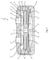
- Fig. 1 is denoted by a temperature-dependent switch 10, which includes a temperature-dependent switching mechanism 11 which is housed in a housing 12.
- the housing 12 comprises a lower part 14 consisting of electrically conductive material and an upper part 15 made of insulating material which closes this and which is held by a flanged edge 16 of the lower part 14 at this. Between the lower part 14 and the upper part 15, a ring 17 is arranged, which is supported on a shoulder 18 of the lower part 14 and there clamps a spring snap disc 21 of the rear derailleur 11 at its edge which is thus permanently electrically connected to the lower part 14.
- the rear derailleur 11 additionally comprises, in addition to the spring snap-action disc 21, a bimetallic snap-action disc 22, which is penetrated centrally together with the spring snap-action disc 21 by a pin-like rivet 23, by which it engages with a current transfer member in the form of a contact plate made of electrically conductive material 24 are mechanically and electrically connected.
- the rivet 23 has a first shoulder 25 on which the bimetal snap disc 22 is seated with radial and axial play, with a second shoulder 26 is provided on which the spring snap disc 21 also sits with radial and axial play.
- the bimetallic snap disk 22 is supported with its peripheral edge inside in the lower part 14.
- the contact plate 24 has, in the direction of the upper part 15, two large-area mating contacts 27 and 28 electrically connected to one another via the contact plate 24, which interact with two stationary contacts 31, 32 arranged on the inner side 29 of the upper part 29, the inner heads of contact rivets 33, 34 are that pass through the upper part 15 and serve with their outer heads as external connections 35, 36.
- the bimetal snap-action disc 22 If the temperature of the bimetal snap-action disc 22 increases beyond its response temperature, it snaps from the convex into a concave shape and supports itself with its edge in the region of the ring 17 and pulls the contact plate 24 against the force of the spring. Snap-action disc 21 away from the stationary contacts 31, 32; the switch 10 is now open.
- a schematically indicated self-holding resistor 37 is provided on the inside of the upper part 15, which is electrically connected in series between the two stationary contacts 31, 32 and when the switch 10 is open a residual current leads through which he so far heats the bimetallic snap disk 22 is maintained at a temperature above its return temperature.
- contact plate 24 is moved in the embodiment shown by a temperature-dependent switching mechanism 11 with a circular spring snap disc 21 and a circular bimetallic snap disk 22, it is also possible to dispense with the spring snap disk and the contact plate 24 only by a bimetal -Schnappulation 22 to hold and move. Further, instead of a circular contact plate 24 and an elongate contact bridge can be used.
- contact plate 24 is held centrally by the bimetallic snap disk 22 and spring snap disk 21 be, it is also possible to use a cantilevered, elongated bimetallic spring, which carries at its free end a contact bridge, as for example from the DE 10 2004 036 117 A1 is known.
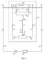
- Fig. 2 is between two connection terminals 39, 40, the interconnection of the temperature-dependent switch 10 from Fig. 1 shown with a controllable semiconductor valve 41 to a dashed rimmed temperature protection circuit 42 which is connected via the connection terminals 39, 40 with a series circuit of an AC voltage source 45 and an electrical device to be protected 46.
- the switch 10 is in Fig. 2 only indicated schematically; the schematically indicated structural features are denoted by the reference numerals as in Fig. 1 Mistake.
- Two connecting lines 43, 44 are connected to the two external terminals 35, 36 of the switch 10, which in turn are connected to the stationary contacts 31, 32, which in the in Fig. 1 shown switching position via the contact plate 24 are short-circuited, which is supported by the switching mechanism 11.
- the external terminals 35, 36 are connected to the connection terminals 39 and 40 of the temperature protection circuit 42, respectively.
- the contact plate 24 is connected via the rear derailleur 11, so here the spring snap-action disc 21 electrically connected to the lower part 14, the in Fig. 2 is indicated by a circle as a connection.
- the semiconductor valve 41 has two power connections 47, 48, which are each connected to one of the connection lines 43, 44. Furthermore, the semiconductor valve 41 has a control input 49, which is connected to the lower part 14 via a control line 50.
- Corrugated sections 51 in the connecting lines 43, 44 and the control line 50 indicate that the semiconductor valve 41 can be connected to the connecting lines 43, 44 at any suitable point.
- the corrugated terminals 51 may be formed as a plug.
- the semiconductor valve 41 can thus be connected at existing or fixed wiring of the switch 10 with the AC voltage source 45 and the device 46 arbitrarily to the connecting lines 43, 44 or external lines 53, 54, which does not newly relocated, but only at the appropriate location for the Connection to the power connectors 47, 48 must be stripped. Only the control line 50 still has to be routed to the switch 10 and connected there to the outside with the lower part 14, whereby the electrical connection to the switching mechanism 11 and via this to the contact plate 24 is produced.
- Fig. 2 the switch 10 is shown in a switching state in which the contact plate 24 is moving away from the stationary contacts 31, 32.
- the semiconductor valve 41 ignites, ie becomes conductive, it takes over the load current and the temperature-dependent switch 10 is de-energized, so that the arcs 55 go out.
- the semiconductor valve 41 closes again when the operating AC voltage 45 reaches the zero crossing, that is, the polarity changes. During this period, the contact plate 24 has so far away from the stationary contacts 31, 32, that it does not come to a rollover and re-forming arcing.
- the self-holding resistor 37 now adopts a residual current, which keeps the switch 10 open even after the device 46 has cooled.
- Fig. 2 is still a heating resistor 56 shown, which is connected in series between the stationary contact 31 and the external terminal 35, that is, one of the connection terminals of the temperature protection circuit 42.
- the lower part 14 While at the switch 10 off Fig. 1 the lower part 14 is electrically conductive, it may also be made of insulating material. Thus, the switching mechanism 11 can still be connected to the control input 49, an additional electrode is required, which establishes the connection to the rear derailleur 11. This may be in the construction of the Fig. 1 be on the shoulder 18 led out laterally tab.
- this may be an electrode connected to the other, the clamped end of the bimetallic spring.
- the two outer terminals 35 and 36 can also serve as connection terminals 39 and 40 at the same time.
- the external lines 53, 54 can also be formed by the connection lines 43 and 44, which are continued to the device 46 and the AC voltage source 45.
Landscapes
- Physics & Mathematics (AREA)
- Thermal Sciences (AREA)
- Thermally Actuated Switches (AREA)
Applications Claiming Priority (2)
| Application Number | Priority Date | Filing Date | Title |
|---|---|---|---|
| DE102012112487.6A DE102012112487A1 (de) | 2012-12-18 | 2012-12-18 | Temperaturschutzschaltung |
| DE202013100509U DE202013100509U1 (de) | 2012-12-18 | 2013-02-05 | Temperaturschutzschaltung |
Publications (2)
| Publication Number | Publication Date |
|---|---|
| EP2747110A1 EP2747110A1 (de) | 2014-06-25 |
| EP2747110B1 true EP2747110B1 (de) | 2016-04-27 |
Family
ID=47909427
Family Applications (2)
| Application Number | Title | Priority Date | Filing Date |
|---|---|---|---|
| EP13195968.6A Active EP2747110B1 (de) | 2012-12-18 | 2013-12-06 | Temperaturschutzschaltung |
| EP13802626.5A Not-in-force EP2867910B1 (de) | 2012-12-18 | 2013-12-10 | Temperaturschutzschaltung |
Family Applications After (1)
| Application Number | Title | Priority Date | Filing Date |
|---|---|---|---|
| EP13802626.5A Not-in-force EP2867910B1 (de) | 2012-12-18 | 2013-12-10 | Temperaturschutzschaltung |
Country Status (9)
| Country | Link |
|---|---|
| US (2) | US9263879B2 (zh) |
| EP (2) | EP2747110B1 (zh) |
| JP (2) | JP2016500508A (zh) |
| CN (2) | CN105103254B (zh) |
| DE (3) | DE102012112487A1 (zh) |
| DK (1) | DK2747110T3 (zh) |
| ES (1) | ES2583502T3 (zh) |
| PL (1) | PL2747110T3 (zh) |
| WO (1) | WO2014095477A1 (zh) |
Families Citing this family (6)
| Publication number | Priority date | Publication date | Assignee | Title |
|---|---|---|---|---|
| DE102012112487A1 (de) | 2012-12-18 | 2014-06-18 | Thermik Gerätebau GmbH | Temperaturschutzschaltung |
| DE102015114248B4 (de) | 2015-08-27 | 2019-01-17 | Marcel P. HOFSAESS | Temperaturabhängiger Schalter mit Schneidgrat |
| CN106026018A (zh) * | 2016-06-22 | 2016-10-12 | 宁波市艾亿赛热保护科技有限公司 | 一种自行发电船舶用的热温度异常保护器 |
| CN109801811A (zh) * | 2019-03-19 | 2019-05-24 | 广州安的电子技术有限公司 | 温度开关 |
| DE102019125450B4 (de) * | 2019-09-20 | 2021-04-08 | Marcel P. HOFSAESS | Temperaturabhängiger Schalter |
| CN113257623B (zh) * | 2021-05-12 | 2022-09-13 | 浙江浩克智能装备有限公司 | 一种智能装置通电保护设备 |
Family Cites Families (26)
| Publication number | Priority date | Publication date | Assignee | Title |
|---|---|---|---|---|
| GB331372A (en) | 1929-06-19 | 1930-07-03 | Coop Wholesale | Improvements in brushes |
| US3549970A (en) * | 1967-12-20 | 1970-12-22 | Alexander J Lewus | Single-phase motor controls with combination overload protector and starting switch |
| US3539775A (en) | 1968-10-10 | 1970-11-10 | American Mach & Foundry | Double-make contact switching apparatus with improved alternating current arc suppression means |
| US3600635A (en) * | 1969-07-15 | 1971-08-17 | Rca Corp | Protection circuit including a thyristor and a three terminal device |
| DE2121802C3 (de) | 1971-05-03 | 1974-10-24 | Thermik-Geraetebau Gmbh + Co, 7530 Pforzheim | Temperaturwächter |
| DE2253975A1 (de) * | 1971-11-04 | 1973-05-10 | Otter Controls Ltd | Elektrischer schalter |
| DE2644411C2 (de) | 1976-10-01 | 1984-08-16 | Hofsäss, Peter, 7530 Pforzheim | Temperaturwächter |
| DE3132338A1 (de) | 1981-08-17 | 1983-03-03 | Brown, Boveri & Cie Ag, 6800 Mannheim | Verfahren zur zuendung von steuerbaren halbleiterventilen, die zur loeschung von schaltlichtboegen elektrischer schaltgeraete dienen |
| US4574229A (en) * | 1983-10-20 | 1986-03-04 | Kim In S | Power efficient motor starter and circuit breaker for an induction motor |
| JPH01303018A (ja) * | 1988-05-30 | 1989-12-06 | Matsushita Refrig Co Ltd | モータの過負荷保護装置 |
| CN2166514Y (zh) | 1993-06-17 | 1994-05-25 | 蔡和平 | 交流接触器无弧放电装置 |
| JP3416229B2 (ja) * | 1993-11-30 | 2003-06-16 | 三洋電機株式会社 | パック電池 |
| JPH09213182A (ja) * | 1996-02-05 | 1997-08-15 | Texas Instr Japan Ltd | モータプロテクタ |
| DE19704563B4 (de) * | 1997-02-07 | 2005-07-21 | Thermik Gerätebau GmbH | Vorrichtung zum Schützen eines Gerätes |
| DE19827113C2 (de) * | 1998-06-18 | 2001-11-29 | Marcel Hofsaes | Temperaturabhängiger Schalter mit Stromübertragungsglied |
| JP2002352685A (ja) * | 2001-05-22 | 2002-12-06 | Ubukata Industries Co Ltd | サーマルプロテクタ |
| DE102004036117B4 (de) | 2004-07-24 | 2006-12-14 | Tmc Sensortechnik Gmbh | Thermobimetallschalter |
| DE102007042903A1 (de) * | 2007-07-02 | 2009-01-08 | Bammert, Jörg | Elektrische Schaltung |
| GB2458650A (en) * | 2008-03-25 | 2009-09-30 | Meiko Pet Corp | Fish tank heater |
| CN101710548A (zh) * | 2009-12-01 | 2010-05-19 | 艾默生网络能源有限公司 | 继电器灭弧电路和方法 |
| FR2958789B1 (fr) * | 2010-04-09 | 2012-05-11 | Abb France | Dispositif de protection contre les surtensions transitoires a deconnecteur thermique ameliore |
| DE102011016142A1 (de) | 2011-03-25 | 2012-09-27 | Marcel P. HOFSAESS | Temperaturabhängiger Schalter mit Stromübertragungsglied |
| DE102011100752A1 (de) * | 2011-05-05 | 2012-11-08 | Thermik Gerätebau GmbH | Schalteinheit mit drei Außenanschlüssen |
| DE102012103306B3 (de) | 2012-04-17 | 2013-04-25 | Thermik Gerätebau GmbH | Temperaturabhängiger Schalter mit Kontaktteil als Heizwiderstand |
| DE102012112487A1 (de) | 2012-12-18 | 2014-06-18 | Thermik Gerätebau GmbH | Temperaturschutzschaltung |
| JP6143615B2 (ja) * | 2013-09-03 | 2017-06-07 | 富士電機株式会社 | 直流開閉器 |
-
2012
- 2012-12-18 DE DE102012112487.6A patent/DE102012112487A1/de not_active Withdrawn
-
2013
- 2013-02-05 DE DE202013100509U patent/DE202013100509U1/de not_active Expired - Lifetime
- 2013-05-14 DE DE202013102091.5U patent/DE202013102091U1/de not_active Expired - Lifetime
- 2013-12-06 PL PL13195968.6T patent/PL2747110T3/pl unknown
- 2013-12-06 ES ES13195968.6T patent/ES2583502T3/es active Active
- 2013-12-06 DK DK13195968.6T patent/DK2747110T3/en active
- 2013-12-06 EP EP13195968.6A patent/EP2747110B1/de active Active
- 2013-12-10 EP EP13802626.5A patent/EP2867910B1/de not_active Not-in-force
- 2013-12-10 JP JP2015548360A patent/JP2016500508A/ja active Pending
- 2013-12-10 CN CN201380072925.0A patent/CN105103254B/zh not_active Expired - Fee Related
- 2013-12-10 US US14/101,638 patent/US9263879B2/en not_active Expired - Fee Related
- 2013-12-10 WO PCT/EP2013/076026 patent/WO2014095477A1/de active Application Filing
- 2013-12-16 CN CN201310689501.0A patent/CN103871779B/zh not_active Expired - Fee Related
- 2013-12-17 JP JP2013259923A patent/JP2014132819A/ja active Pending
-
2015
- 2015-06-09 US US14/734,606 patent/US10027109B2/en not_active Expired - Fee Related
Also Published As
| Publication number | Publication date |
|---|---|
| CN105103254B (zh) | 2018-07-06 |
| CN105103254A (zh) | 2015-11-25 |
| EP2867910A1 (de) | 2015-05-06 |
| DE202013102091U1 (de) | 2014-03-19 |
| EP2747110A1 (de) | 2014-06-25 |
| US20140168844A1 (en) | 2014-06-19 |
| DE102012112487A1 (de) | 2014-06-18 |
| CN103871779B (zh) | 2017-06-16 |
| PL2747110T3 (pl) | 2016-11-30 |
| DE202013100509U1 (de) | 2013-02-15 |
| EP2867910B1 (de) | 2016-09-28 |
| JP2016500508A (ja) | 2016-01-12 |
| WO2014095477A1 (de) | 2014-06-26 |
| ES2583502T3 (es) | 2016-09-21 |
| US20150270698A1 (en) | 2015-09-24 |
| JP2014132819A (ja) | 2014-07-17 |
| US9263879B2 (en) | 2016-02-16 |
| CN103871779A (zh) | 2014-06-18 |
| US10027109B2 (en) | 2018-07-17 |
| DK2747110T3 (en) | 2016-08-15 |
Similar Documents
| Publication | Publication Date | Title |
|---|---|---|
| EP2747110B1 (de) | Temperaturschutzschaltung | |
| EP2980822B1 (de) | Schutzschaltgerät und magnetjoch | |
| EP2553691B1 (de) | Überspannungsschutzeinrichtung, umfassend mindestens einen überspannungsableiter | |
| EP0966014B1 (de) | Temperaturabhängiger Schalter mit Stromübertragungsglied | |
| DE102015217704A1 (de) | Lichtbogen-Löschvorrichtung und Schutzschaltgerät | |
| EP2874171B1 (de) | Temperaturabhängiges schaltwerk | |
| DE202006020737U1 (de) | Passive oder aktive Kurzschließeinrichtung für den Einsatz in Nieder- und Mittelspannungsanlagen zum Sach- und Personenschutz | |
| DE102011101862B4 (de) | Temperaturabhängiger Schalter mit Stromübertragungsglied | |
| DE102013101393B4 (de) | Temperaturabhängiger Schalter | |
| EP0920044B1 (de) | Schalter mit einem temperaturabhängigen Schaltwerk | |
| DE202014002496U1 (de) | Überspannungsschutzeinrichtung, umfassend mindestens einen Überspannungsableiter und eine dem Überspannungsableiter parallel geschaltete, thermisch auslösbare, federvorgespannte Kurzschliessschalteinrichtung | |
| DE102014108518A1 (de) | Temperaturabhängiger Schalter mit Distanzring | |
| EP0828273B1 (de) | Schalter mit einem Sicherheitselement | |
| EP0994497B1 (de) | Schalter mit einem Isolierstoffträger | |
| EP2697881B2 (de) | Zweistufige abschaltvorrichtung | |
| EP0938116B1 (de) | Schalter | |
| DE2625715A1 (de) | Leistungssteuergeraet | |
| EP3229255B1 (de) | Temperaturabhängiger schalter | |
| DE19909059A1 (de) | Schalter mit Verschweißsicherung | |
| DE2511214A1 (de) | Temperatur-sicherheitseinrichtung fuer elektrische geraete, insbesondere haushaltgeraete | |
| DE102015217694A1 (de) | Lichtbogen-Löschvorrichtung und Schutzschaltgerät | |
| EP4411777A1 (de) | Temperaturabhängiger schalter | |
| DE102015201289A1 (de) | Anordnung mit einem wärmeisolierenden Schalter und einer Wärmeisolierung | |
| DE202016007195U1 (de) | Strombegrenzende Schalteinrichtung | |
| DD220751A1 (de) | Anordnung zum schmieren der kontakte von elektrischen schaltern |
Legal Events
| Date | Code | Title | Description |
|---|---|---|---|
| PUAI | Public reference made under article 153(3) epc to a published international application that has entered the european phase |
Free format text: ORIGINAL CODE: 0009012 |
|
| 17P | Request for examination filed |
Effective date: 20131206 |
|
| AK | Designated contracting states |
Kind code of ref document: A1 Designated state(s): AL AT BE BG CH CY CZ DE DK EE ES FI FR GB GR HR HU IE IS IT LI LT LU LV MC MK MT NL NO PL PT RO RS SE SI SK SM TR |
|
| AX | Request for extension of the european patent |
Extension state: BA ME |
|
| R17P | Request for examination filed (corrected) |
Effective date: 20141209 |
|
| RBV | Designated contracting states (corrected) |
Designated state(s): AL AT BE BG CH CY CZ DE DK EE ES FI FR GB GR HR HU IE IS IT LI LT LU LV MC MK MT NL NO PL PT RO RS SE SI SK SM TR |
|
| GRAP | Despatch of communication of intention to grant a patent |
Free format text: ORIGINAL CODE: EPIDOSNIGR1 |
|
| INTG | Intention to grant announced |
Effective date: 20151126 |
|
| GRAS | Grant fee paid |
Free format text: ORIGINAL CODE: EPIDOSNIGR3 |
|
| GRAA | (expected) grant |
Free format text: ORIGINAL CODE: 0009210 |
|
| AK | Designated contracting states |
Kind code of ref document: B1 Designated state(s): AL AT BE BG CH CY CZ DE DK EE ES FI FR GB GR HR HU IE IS IT LI LT LU LV MC MK MT NL NO PL PT RO RS SE SI SK SM TR |
|
| REG | Reference to a national code |
Ref country code: GB Ref legal event code: FG4D Free format text: NOT ENGLISH |
|
| REG | Reference to a national code |
Ref country code: CH Ref legal event code: EP |
|
| REG | Reference to a national code |
Ref country code: AT Ref legal event code: REF Ref document number: 795611 Country of ref document: AT Kind code of ref document: T Effective date: 20160515 |
|
| REG | Reference to a national code |
Ref country code: IE Ref legal event code: FG4D Free format text: LANGUAGE OF EP DOCUMENT: GERMAN |
|
| REG | Reference to a national code |
Ref country code: DE Ref legal event code: R096 Ref document number: 502013002768 Country of ref document: DE |
|
| REG | Reference to a national code |
Ref country code: CH Ref legal event code: NV Representative=s name: RENTSCH PARTNER AG, CH |
|
| REG | Reference to a national code |
Ref country code: NL Ref legal event code: FP |
|
| REG | Reference to a national code |
Ref country code: DK Ref legal event code: T3 Effective date: 20160802 |
|
| REG | Reference to a national code |
Ref country code: SE Ref legal event code: TRGR |
|
| REG | Reference to a national code |
Ref country code: LT Ref legal event code: MG4D |
|
| REG | Reference to a national code |
Ref country code: ES Ref legal event code: FG2A Ref document number: 2583502 Country of ref document: ES Kind code of ref document: T3 Effective date: 20160921 |
|
| PG25 | Lapsed in a contracting state [announced via postgrant information from national office to epo] |
Ref country code: FI Free format text: LAPSE BECAUSE OF FAILURE TO SUBMIT A TRANSLATION OF THE DESCRIPTION OR TO PAY THE FEE WITHIN THE PRESCRIBED TIME-LIMIT Effective date: 20160427 Ref country code: NO Free format text: LAPSE BECAUSE OF FAILURE TO SUBMIT A TRANSLATION OF THE DESCRIPTION OR TO PAY THE FEE WITHIN THE PRESCRIBED TIME-LIMIT Effective date: 20160727 Ref country code: LT Free format text: LAPSE BECAUSE OF FAILURE TO SUBMIT A TRANSLATION OF THE DESCRIPTION OR TO PAY THE FEE WITHIN THE PRESCRIBED TIME-LIMIT Effective date: 20160427 |
|
| PG25 | Lapsed in a contracting state [announced via postgrant information from national office to epo] |
Ref country code: LV Free format text: LAPSE BECAUSE OF FAILURE TO SUBMIT A TRANSLATION OF THE DESCRIPTION OR TO PAY THE FEE WITHIN THE PRESCRIBED TIME-LIMIT Effective date: 20160427 Ref country code: GR Free format text: LAPSE BECAUSE OF FAILURE TO SUBMIT A TRANSLATION OF THE DESCRIPTION OR TO PAY THE FEE WITHIN THE PRESCRIBED TIME-LIMIT Effective date: 20160728 Ref country code: HR Free format text: LAPSE BECAUSE OF FAILURE TO SUBMIT A TRANSLATION OF THE DESCRIPTION OR TO PAY THE FEE WITHIN THE PRESCRIBED TIME-LIMIT Effective date: 20160427 Ref country code: PT Free format text: LAPSE BECAUSE OF FAILURE TO SUBMIT A TRANSLATION OF THE DESCRIPTION OR TO PAY THE FEE WITHIN THE PRESCRIBED TIME-LIMIT Effective date: 20160829 Ref country code: RS Free format text: LAPSE BECAUSE OF FAILURE TO SUBMIT A TRANSLATION OF THE DESCRIPTION OR TO PAY THE FEE WITHIN THE PRESCRIBED TIME-LIMIT Effective date: 20160427 |
|
| REG | Reference to a national code |
Ref country code: DE Ref legal event code: R097 Ref document number: 502013002768 Country of ref document: DE |
|
| PG25 | Lapsed in a contracting state [announced via postgrant information from national office to epo] |
Ref country code: RO Free format text: LAPSE BECAUSE OF FAILURE TO SUBMIT A TRANSLATION OF THE DESCRIPTION OR TO PAY THE FEE WITHIN THE PRESCRIBED TIME-LIMIT Effective date: 20160427 Ref country code: EE Free format text: LAPSE BECAUSE OF FAILURE TO SUBMIT A TRANSLATION OF THE DESCRIPTION OR TO PAY THE FEE WITHIN THE PRESCRIBED TIME-LIMIT Effective date: 20160427 Ref country code: CZ Free format text: LAPSE BECAUSE OF FAILURE TO SUBMIT A TRANSLATION OF THE DESCRIPTION OR TO PAY THE FEE WITHIN THE PRESCRIBED TIME-LIMIT Effective date: 20160427 Ref country code: SK Free format text: LAPSE BECAUSE OF FAILURE TO SUBMIT A TRANSLATION OF THE DESCRIPTION OR TO PAY THE FEE WITHIN THE PRESCRIBED TIME-LIMIT Effective date: 20160427 |
|
| PG25 | Lapsed in a contracting state [announced via postgrant information from national office to epo] |
Ref country code: SM Free format text: LAPSE BECAUSE OF FAILURE TO SUBMIT A TRANSLATION OF THE DESCRIPTION OR TO PAY THE FEE WITHIN THE PRESCRIBED TIME-LIMIT Effective date: 20160427 |
|
| PLBE | No opposition filed within time limit |
Free format text: ORIGINAL CODE: 0009261 |
|
| STAA | Information on the status of an ep patent application or granted ep patent |
Free format text: STATUS: NO OPPOSITION FILED WITHIN TIME LIMIT |
|
| 26N | No opposition filed |
Effective date: 20170130 |
|
| PG25 | Lapsed in a contracting state [announced via postgrant information from national office to epo] |
Ref country code: SI Free format text: LAPSE BECAUSE OF FAILURE TO SUBMIT A TRANSLATION OF THE DESCRIPTION OR TO PAY THE FEE WITHIN THE PRESCRIBED TIME-LIMIT Effective date: 20160427 Ref country code: BE Free format text: LAPSE BECAUSE OF NON-PAYMENT OF DUE FEES Effective date: 20161231 |
|
| REG | Reference to a national code |
Ref country code: DK Ref legal event code: EBP Effective date: 20161231 Ref country code: CH Ref legal event code: PL |
|
| REG | Reference to a national code |
Ref country code: SE Ref legal event code: EUG |
|
| PG25 | Lapsed in a contracting state [announced via postgrant information from national office to epo] |
Ref country code: SE Free format text: LAPSE BECAUSE OF NON-PAYMENT OF DUE FEES Effective date: 20161207 |
|
| PG25 | Lapsed in a contracting state [announced via postgrant information from national office to epo] |
Ref country code: MC Free format text: LAPSE BECAUSE OF FAILURE TO SUBMIT A TRANSLATION OF THE DESCRIPTION OR TO PAY THE FEE WITHIN THE PRESCRIBED TIME-LIMIT Effective date: 20160427 |
|
| REG | Reference to a national code |
Ref country code: FR Ref legal event code: ST Effective date: 20170831 |
|
| REG | Reference to a national code |
Ref country code: IE Ref legal event code: MM4A |
|
| PG25 | Lapsed in a contracting state [announced via postgrant information from national office to epo] |
Ref country code: LI Free format text: LAPSE BECAUSE OF NON-PAYMENT OF DUE FEES Effective date: 20161231 Ref country code: FR Free format text: LAPSE BECAUSE OF NON-PAYMENT OF DUE FEES Effective date: 20170102 Ref country code: LU Free format text: LAPSE BECAUSE OF NON-PAYMENT OF DUE FEES Effective date: 20161206 Ref country code: CH Free format text: LAPSE BECAUSE OF NON-PAYMENT OF DUE FEES Effective date: 20161231 |
|
| PG25 | Lapsed in a contracting state [announced via postgrant information from national office to epo] |
Ref country code: IE Free format text: LAPSE BECAUSE OF NON-PAYMENT OF DUE FEES Effective date: 20161206 |
|
| PG25 | Lapsed in a contracting state [announced via postgrant information from national office to epo] |
Ref country code: DK Free format text: LAPSE BECAUSE OF NON-PAYMENT OF DUE FEES Effective date: 20161231 |
|
| PGFP | Annual fee paid to national office [announced via postgrant information from national office to epo] |
Ref country code: NL Payment date: 20171219 Year of fee payment: 5 |
|
| REG | Reference to a national code |
Ref country code: BE Ref legal event code: MM Effective date: 20161231 |
|
| PG25 | Lapsed in a contracting state [announced via postgrant information from national office to epo] |
Ref country code: PL Free format text: LAPSE BECAUSE OF NON-PAYMENT OF DUE FEES Effective date: 20161206 |
|
| PG25 | Lapsed in a contracting state [announced via postgrant information from national office to epo] |
Ref country code: ES Free format text: LAPSE BECAUSE OF NON-PAYMENT OF DUE FEES Effective date: 20171207 Ref country code: HU Free format text: LAPSE BECAUSE OF FAILURE TO SUBMIT A TRANSLATION OF THE DESCRIPTION OR TO PAY THE FEE WITHIN THE PRESCRIBED TIME-LIMIT; INVALID AB INITIO Effective date: 20131206 |
|
| REG | Reference to a national code |
Ref country code: ES Ref legal event code: FD2A Effective date: 20180625 |
|
| PG25 | Lapsed in a contracting state [announced via postgrant information from national office to epo] |
Ref country code: CY Free format text: LAPSE BECAUSE OF FAILURE TO SUBMIT A TRANSLATION OF THE DESCRIPTION OR TO PAY THE FEE WITHIN THE PRESCRIBED TIME-LIMIT Effective date: 20160427 Ref country code: IS Free format text: LAPSE BECAUSE OF FAILURE TO SUBMIT A TRANSLATION OF THE DESCRIPTION OR TO PAY THE FEE WITHIN THE PRESCRIBED TIME-LIMIT Effective date: 20160427 Ref country code: MK Free format text: LAPSE BECAUSE OF FAILURE TO SUBMIT A TRANSLATION OF THE DESCRIPTION OR TO PAY THE FEE WITHIN THE PRESCRIBED TIME-LIMIT Effective date: 20160427 |
|
| PG25 | Lapsed in a contracting state [announced via postgrant information from national office to epo] |
Ref country code: BG Free format text: LAPSE BECAUSE OF FAILURE TO SUBMIT A TRANSLATION OF THE DESCRIPTION OR TO PAY THE FEE WITHIN THE PRESCRIBED TIME-LIMIT Effective date: 20160427 Ref country code: ES Free format text: LAPSE BECAUSE OF NON-PAYMENT OF DUE FEES Effective date: 20161207 |
|
| GBPC | Gb: european patent ceased through non-payment of renewal fee |
Effective date: 20171206 |
|
| PG25 | Lapsed in a contracting state [announced via postgrant information from national office to epo] |
Ref country code: MT Free format text: LAPSE BECAUSE OF FAILURE TO SUBMIT A TRANSLATION OF THE DESCRIPTION OR TO PAY THE FEE WITHIN THE PRESCRIBED TIME-LIMIT Effective date: 20160427 |
|
| PG25 | Lapsed in a contracting state [announced via postgrant information from national office to epo] |
Ref country code: AL Free format text: LAPSE BECAUSE OF FAILURE TO SUBMIT A TRANSLATION OF THE DESCRIPTION OR TO PAY THE FEE WITHIN THE PRESCRIBED TIME-LIMIT Effective date: 20160427 Ref country code: TR Free format text: LAPSE BECAUSE OF FAILURE TO SUBMIT A TRANSLATION OF THE DESCRIPTION OR TO PAY THE FEE WITHIN THE PRESCRIBED TIME-LIMIT Effective date: 20160427 |
|
| PG25 | Lapsed in a contracting state [announced via postgrant information from national office to epo] |
Ref country code: GB Free format text: LAPSE BECAUSE OF NON-PAYMENT OF DUE FEES Effective date: 20171206 |
|
| REG | Reference to a national code |
Ref country code: NL Ref legal event code: MM Effective date: 20190101 |
|
| PG25 | Lapsed in a contracting state [announced via postgrant information from national office to epo] |
Ref country code: NL Free format text: LAPSE BECAUSE OF NON-PAYMENT OF DUE FEES Effective date: 20190101 |
|
| REG | Reference to a national code |
Ref country code: AT Ref legal event code: MM01 Ref document number: 795611 Country of ref document: AT Kind code of ref document: T Effective date: 20181206 |
|
| PGFP | Annual fee paid to national office [announced via postgrant information from national office to epo] |
Ref country code: IT Payment date: 20191230 Year of fee payment: 7 |
|
| PG25 | Lapsed in a contracting state [announced via postgrant information from national office to epo] |
Ref country code: AT Free format text: LAPSE BECAUSE OF NON-PAYMENT OF DUE FEES Effective date: 20181206 |
|
| PG25 | Lapsed in a contracting state [announced via postgrant information from national office to epo] |
Ref country code: IT Free format text: LAPSE BECAUSE OF NON-PAYMENT OF DUE FEES Effective date: 20201206 |
|
| P01 | Opt-out of the competence of the unified patent court (upc) registered |
Effective date: 20230508 |
|
| PGFP | Annual fee paid to national office [announced via postgrant information from national office to epo] |
Ref country code: DE Payment date: 20240129 Year of fee payment: 11 |