EP2746754A2 - Nichtlineare Lösung zur 2D-Phasenverschiebung - Google Patents
Nichtlineare Lösung zur 2D-Phasenverschiebung Download PDFInfo
- Publication number
- EP2746754A2 EP2746754A2 EP13199391.7A EP13199391A EP2746754A2 EP 2746754 A2 EP2746754 A2 EP 2746754A2 EP 13199391 A EP13199391 A EP 13199391A EP 2746754 A2 EP2746754 A2 EP 2746754A2
- Authority
- EP
- European Patent Office
- Prior art keywords
- images
- phase
- captured
- fringe pattern
- cos
- Prior art date
- Legal status (The legal status is an assumption and is not a legal conclusion. Google has not performed a legal analysis and makes no representation as to the accuracy of the status listed.)
- Withdrawn
Links
Images





Classifications
-
- G—PHYSICS
- G01—MEASURING; TESTING
- G01N—INVESTIGATING OR ANALYSING MATERIALS BY DETERMINING THEIR CHEMICAL OR PHYSICAL PROPERTIES
- G01N23/00—Investigating or analysing materials by the use of wave or particle radiation, e.g. X-rays or neutrons, not covered by groups G01N3/00 – G01N17/00, G01N21/00 or G01N22/00
- G01N23/02—Investigating or analysing materials by the use of wave or particle radiation, e.g. X-rays or neutrons, not covered by groups G01N3/00 – G01N17/00, G01N21/00 or G01N22/00 by transmitting the radiation through the material
- G01N23/04—Investigating or analysing materials by the use of wave or particle radiation, e.g. X-rays or neutrons, not covered by groups G01N3/00 – G01N17/00, G01N21/00 or G01N22/00 by transmitting the radiation through the material and forming images of the material
- G01N23/041—Phase-contrast imaging, e.g. using grating interferometers
-
- G—PHYSICS
- G01—MEASURING; TESTING
- G01N—INVESTIGATING OR ANALYSING MATERIALS BY DETERMINING THEIR CHEMICAL OR PHYSICAL PROPERTIES
- G01N23/00—Investigating or analysing materials by the use of wave or particle radiation, e.g. X-rays or neutrons, not covered by groups G01N3/00 – G01N17/00, G01N21/00 or G01N22/00
- G01N23/20—Investigating or analysing materials by the use of wave or particle radiation, e.g. X-rays or neutrons, not covered by groups G01N3/00 – G01N17/00, G01N21/00 or G01N22/00 by using diffraction of the radiation by the materials, e.g. for investigating crystal structure; by using scattering of the radiation by the materials, e.g. for investigating non-crystalline materials; by using reflection of the radiation by the materials
- G01N23/20075—Investigating or analysing materials by the use of wave or particle radiation, e.g. X-rays or neutrons, not covered by groups G01N3/00 – G01N17/00, G01N21/00 or G01N22/00 by using diffraction of the radiation by the materials, e.g. for investigating crystal structure; by using scattering of the radiation by the materials, e.g. for investigating non-crystalline materials; by using reflection of the radiation by the materials by measuring interferences of X-rays, e.g. Borrmann effect
-
- G—PHYSICS
- G06—COMPUTING OR CALCULATING; COUNTING
- G06T—IMAGE DATA PROCESSING OR GENERATION, IN GENERAL
- G06T12/00—Tomographic reconstruction from projections
Definitions
- phase contrast imaging In the last century or so a large number of techniques have been developed to make (normally invisible) phase variations visible in imaging devices. These techniques include: Zernike phase contrast, Nomarski differential interference contrast, generalized phase contrast, Foucault knife edge, schlieren, shadowgraph, dark-field and wire-test. More recently there has been progress in extending some of these techniques to X-ray imaging. A number of new phase-contrast techniques have been developed for the particularly difficult nature of X-rays, arising primarily from the difficulty of focusing and imaging X-ray beams. These techniques include TIE (Transport of Intensity Equation) phase contrast imaging and ptychography.
- TIE Transport of Intensity Equation
- X-ray Talbot moiré interferometry X-ray Talbot moiré interferometry
- XTMI X-ray Talbot moiré interferometry
- Phase shifting methods have also been applied to x-ray Talbot moiré interferometry.
- linear gratings which are only sensitive to one gradient direction, it is known that if higher harmonics can be ignored, then a minimum of three images are required to recover the low frequency background intensity, the fringe modulation amplitude and the phase parameters, at a point in the image.
- this system is only sensitive to the differential behaviour orthogonal to the grating. Rotating the grating and taking a further two exposures allows the differential phase and modulation parameters in the orthogonal direction to be obtained with a total of only five exposures. Mechanically, this is complex and required a rotation of the grating by 90° during the measurement.
- Crossed or two-dimension (2D) gratings allow the system to be sensitive to the differential phase and the modulation in two orthogonal directions at the same time.
- This modulated sinusoid arises from one element of the pair of gratings that form the crossed grating.
- the third term has the same general form but arises from the second element of the crossed grating.
- the fourth and fifth terms appear similar in form but arise from interactions of the second and third terms.
- This formulation of the intensity has nine unknown parameters, so at least nine phase-stepped images, producing nine intensity values (Z 1 to Z 9 ) associated with nine equations are required to solve for the nine unknowns.
- phase steps must have the precise values imposed by the model used in order to fit the observations. Any variation in the phase step from the nominal phase step required by the analysis will induce errors in the resulting parameters recovered by the analysis since the analysis methods explicitly assume the nominal phase steps. However, because the phase steps are produced by very small mechanical movements in the system, significant errors typically occur in the resulting phase steps. Although there are known methods for correcting for these phase step errors for interferometric phase shifting with one-dimensional (1D) fringe systems, there are no known methods for correcting for phase step errors for crossed grating x-ray Talbot moiré interferometry. A need exists for a method of analysis for these systems that can correct for these phase errors.
- the images are captured by an x-ray interferometer having a crossed diffraction grating.
- a set of captured fringe pattern interferogram images from the x-ray interferometer are provided, the set comprises no more than eight captured fringe pattern interferogram images.
- the method determines an estimate of an absorption parameter ( a ), two-dimensional amplitude modulation parameters (m x , m y ), and two-dimensional phase modulation parameters ( ⁇ x and ⁇ y ) from an appropriate closed-form solution using the received set of captured fringe pattern interferogram images, and reconstructs the representative detailed phase image using the parameter estimates.
- the determining step (220) comprises: obtaining (310) an initial estimate of the parameters; using (320) a phase estimation method to correct phase step errors in the parameters; and iteratively (330) determining an optimal solution (Eqn 27) for the parameters using the corrected phase steps.
- ⁇ x [0, 2 ⁇ /5, 4 ⁇ /5, 6 ⁇ /5, 8 ⁇ /5]
- ⁇ y [0, 6 ⁇ /5, 2 ⁇ /5, 8 ⁇ /5, 4 ⁇ /5]
- a method of reconstructing a representative detailed phase image from a set of fringe pattern interferogram images of an object captured by an x-ray interferometer having a crossed diffraction grating comprises providing a set of captured images; providing a reconstruction technique capable of reconstructing the image from no more than eight images by relating cross components associated with the fringe pattern to the principle components associated with the fringe pattern; and reconstructing the representative detailed phase image from the provided set of captured images using the provided reconstruction technique.
- the present disclosure relates to extracting phase information from a set of interferogram images obtained from an X-ray Talbot interferometry system using a phase shifting technique.
- An X-ray Talbot interferometry system captures fringe patterns generated by an object through a number of gratings using the Talbot effect in order to recover information about the object. Because this type of X-ray imaging uses phase differences instead of absorption to produce contrast, the accuracy is higher than regular X-ray imaging.
- X-ray Talbot interferometry (XTI) system 400 is shown in Fig. 4 , where a phase grating G1 (410) and an object 402 being imaged are both illuminated by X-rays.
- a self-image 420 is formed at a position behind the phase grating G1 due to Talbot effect. Since the phase of the X-ray wave is perturbed by the object 402, the self-image 420 is deformed. By analysing the deformed self-image, the characteristics of the object 402 can be deduced.
- an absorption grating G2 (430) is placed at the position of the self-image 420 to generate a moiré fringe pattern.
- An image sensor 440 is proximate to the absorption grating 430 and configured to capture the moiré fringe pattern.
- the period of the absorption grating G2 (430) is configured to be similar to that of the self-image 420 so the moiré pattern generated by superposing the self-image 420 and the absorption grating G2 (430) amplifies the intensity changes of the self-image permitting the image sensor 440 to more readily resolve the pattern.
- a phase shifting technique may be applied to recover the absorption, amplitude modulation and phase modulation caused by the object.
- a set of images are captured with the gratings shifted between each capture so that temporal samples along the optical path are obtained through spatial shifts of the moiré pattern.
- the phase shifting technique will be described in detail later in this document.
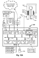
- the computer system 1300 includes: a computer module 1301; input devices such as a keyboard 1302, a mouse pointer device 1303, a scanner 1326, a camera 1327, and a microphone 1380; and output devices including a printer 1315, a display device 1314 and loudspeakers 1317.
- the computer module 1301 is also shown coupled via a connection 1323 to an X-ray apparatus 1399 configured according to the arrangement of Fig. 4 .
- the X-ray apparatus 1399 is configured for imaging the torso of a subject 1324, representing the object 402 of Fig. 4 .
- the computer module 1301 typically includes at least one processor unit 1305, and a memory unit 1306.
- the memory unit 1306 may have semiconductor random access memory (RAM) and semiconductor read only memory (ROM).
- the computer module 1301 also includes an number of input/output (I/O) interfaces including: an audio-video interface 1307 that couples to the video display 1314, loudspeakers 1317 and microphone 1380; an I/O interface 1313 that couples to the keyboard 1302, mouse 1303, scanner 1326, camera 1327 and optionally a joystick or other human interface device (not illustrated); and an interface 1308 for the external modem 1316 and printer 1315.
- the modem 1316 may be incorporated within the computer module 1301, for example within the interface 1308.
- the computer module 1301 also has a local interface 1311, which permits coupling of the computer system 1300 via the connection 1323 to the X-ray apparatus 1399.
- the interfaces 1308 and 1311 may be configured to operate on respective standards, such as EthernetTM, a BluetoothTM wireless arrangement or an IEEE 802.11 wireless arrangement; however, numerous other types of interfaces may be practiced.
- the connection 1323 is typically bidirectional enabling automated X-ray image capture by the apparatus 1399 under direction of the computer 1301 and for the communication of captured image data to the computer 1301 for storage in the memory 1306 or HDD 1310.
- the I/O interfaces 1308 and 1313 may afford either or both of serial and parallel connectivity, the former typically being implemented according to the Universal Serial Bus (USB) standards and having corresponding USB connectors (not illustrated).
- Storage devices 1309 are provided and typically include a hard disk drive (HDD) 1310. Other storage devices such as a floppy disk drive and a magnetic tape drive (not illustrated) may also be used.
- An optical disk drive 1312 is typically provided to act as a non-volatile source of data.
- Portable memory devices such optical disks (e.g., CD-ROM, DVD, Blu ray DiscTM), USB-RAM, portable, external hard drives, and floppy disks, for example, may be used as appropriate sources of data to the system 1300.
- the methods of phase demodulation may be implemented using the computer system 1300 wherein the processes of Figs. 1 to 12 , to be described, may be implemented as one or more software application programs 1333 executable within the computer system 1300.
- the steps of the methods of phase demodulation are effected by instructions 1331 (see Fig. 13B ) in the software 1333 that are carried out within the computer system 1300.
- the software instructions 1331 may be formed as one or more code modules, each for performing one or more particular tasks.
- the software may also be divided into two separate parts, in which a first part and the corresponding code modules performs the phase demodulation methods and a second part and the corresponding code modules manage a user interface between the first part and the user.
- Examples of such storage media include floppy disks, magnetic tape, CD-ROM, DVD, Blu-ray DiscTM, a hard disk drive, a ROM or integrated circuit, USB memory, a magneto-optical disk, or a computer readable card such as a PCMCIA card and the like, whether or not such devices are internal or external of the computer module 1301.
- Examples of transitory or non-tangible computer readable transmission media that may also participate in the provision of software, application programs, instructions and/or data to the computer module 1301 include radio or infra-red transmission channels as well as a network connection to another computer or networked device, and the Internet or Intranets including e-mail transmissions and information recorded on Websites and the like.
- the second part of the application programs 1333 and the corresponding code modules mentioned above may be executed to implement one or more graphical user interfaces (GUIs) to be rendered or otherwise represented upon the display 1314.
- GUIs graphical user interfaces
- a user of the computer system 1300 and the application may manipulate the interface in a functionally adaptable manner to provide controlling commands and/or input to the applications associated with the GUI(s).
- Other forms of functionally adaptable user interfaces may also be implemented, such as an audio interface utilizing speech prompts output via the loudspeakers 1317 and user voice commands input via the microphone 1380.
- Fig. 13B is a detailed schematic block diagram of the processor 1305 and a "memory" 1334.
- the memory 1334 represents a logical aggregation of all the memory modules (including the HDD 1309 and semiconductor memory 1306) that can be accessed by the computer module 1301 in Fig. 13A .
- the operating system 1353 manages the memory 1334 (1309, 1306) to ensure that each process or application running on the computer module 1301 has sufficient memory in which to execute without colliding with memory allocated to another process. Furthermore, the different types of memory available in the system 1300 of Fig. 13A must be used properly so that each process can run effectively. Accordingly, the aggregated memory 1334 is not intended to illustrate how particular segments of memory are allocated (unless otherwise stated), but rather to provide a general view of the memory accessible by the computer system 1300 and how such is used.
- the processor 1305 includes a number of functional modules including a control unit 1339, an arithmetic logic unit (ALU) 1340, and a local or internal memory 1348, sometimes called a cache memory.
- the cache memory 1348 typically includes a number of storage registers 1344 - 1346 in a register section.
- One or more internal busses 1341 functionally interconnect these functional modules.
- the processor 1305 typically also has one or more interfaces 1342 for communicating with external devices via the system bus 1304, using a connection 1318.
- the memory 1334 is coupled to the bus 1304 using a connection 1319.
- the application program 1333 includes a sequence of instructions 1331 that may include conditional branch and loop instructions.
- the program 1333 may also include data 1332 which is used in execution of the program 1333.
- the instructions 1331 and the data 1332 are stored in memory locations 1328, 1329, 1330 and 1335, 1336, 1337, respectively.
- a particular instruction may be stored in a single memory location as depicted by the instruction shown in the memory location 1330.
- an instruction may be segmented into a number of parts each of which is stored in a separate memory location, as depicted by the instruction segments shown in the memory locations 1328 and 1329.
- the processor 1305 is given a set of instructions which are executed therein.
- the processor 1305 waits for a subsequent input, to which the processor 1305 reacts to by executing another set of instructions.
- Each input may be provided from one or more of a number of sources, including data generated by one or more of the input devices 1302, 1303, data received from an external source across one of the networks 1320, 1302, data retrieved from one of the storage devices 1306, 1309 or data retrieved from a storage medium 1325 inserted into the corresponding reader 1312, all depicted in Fig. 13A .
- the execution of a set of the instructions may in some cases result in output of data. Execution may also involve storing data or variables to the memory 1334.
- the disclosed image processing arrangements use input variables 1354, which are stored in the memory 1334 in corresponding memory locations 1355, 1356, 1357.
- the image processing arrangements produce output variables 1361, which are stored in the memory 1334 in corresponding memory locations 1362, 1363, 1364.
- Intermediate variables 1358 may be stored in memory locations 1359, 1360, 1366 and 1367.
- each fetch, decode, and execute cycle comprises:
- a further fetch, decode, and execute cycle for the next instruction may be executed.
- a store cycle may be performed by which the control unit 1339 stores or writes a value to a memory location 1332.
- Each step or sub-process in the processes of Figs. 1 to 12 is associated with one or more segments of the program 1333 and is performed by the register section 1344, 1345, 1347, the ALU 1340, and the control unit 1339 in the processor 1305 working together to perform the fetch, decode, and execute cycles for every instruction in the instruction set for the noted segments of the program 1333.
- the methods of image processing may alternatively be implemented in whole or part using dedicated hardware such as one or more integrated circuits performing the functions or sub functions of image processing.
- dedicated hardware may include graphic processors, digital signal processors, or one or more microprocessors and associated memories.
- the gratings used in crossed grating X-ray Talbot moiré interferometry are created by etching holes in silicon wafers.
- the accuracy constraints on the fabrication process means that these holes tend to be more round than the ideal square profile, such as depicted in Fig. 5 .
- the square profile is not practically achievable it does make a convenient starting point for the analysis.
- Z n a ⁇ 1 + m x cos ⁇ x + ⁇ x , n ⁇ 1 + m y ⁇ cos ⁇ y + ⁇ y , n
- a is the overall absorption factor
- m x is the modulation of the x component
- m y is the modulation of the y component
- ⁇ x is the phase of the x component
- ⁇ y is the phase of the y component
- ⁇ x,n is the imposed phase step in the x component
- ⁇ y,n is the imposed phase step in the y component.
- Equation (4) The nature of the gratings used in an X-ray Talbot system 400 means that there will be some harmonics in the resulting image. However, the strength of the harmonics is usually very low due to the modulation translation function (MTF) of the optical system, including the effects of the sensor 440. Those harmonics are therefore ignored in Equation (4).
- MTF modulation translation function
- Equation (4) In order to solve Equation (4) for a, m x , m y , ⁇ x and ⁇ y , a sequence of images must be captured. If the captured intensity is well modelled by a separable modulation in each of the x and y directions as in Equation (4), it is theoretically possible to solve the system in Equation (4) using as few as 5 captures.
- the moiré interferogram produced by the X-ray Talbot system 400 cannot strictly be represented by a separable form like Equation (4).
- the separable representation is expanded and adapted in form as follows:
- Z n a ⁇ 1 + m x ⁇ cos ⁇ x + ⁇ x , n + m y ⁇ cos ⁇ y + ⁇ y , n + b ⁇ m x ⁇ m y ⁇ cos ⁇ x + ⁇ x , n ⁇ cos ⁇ y + ⁇ y , n
- the modulation of the cross terms is modified by a factor b .
- Fig. 1 depicts a method 100 offering a closed-form solution.
- the method 100 is preferably implemented as software executable on the computer system 1300 working in concert with the X-ray apparatus 1399.
- Step 110 captures the fringe pattern interferogram images which are provided to the computer 1301 for storage and processing. In some applications, the images may be captured by remote X-ray apparatus and communicated to the computer via the network 1320.
- the computer 1301 then executes an application in step 120 to estimate the five parameters: a, m x , m y , ⁇ x and ⁇ y from the moiré image data obtained from the captures of step 110 using a closed-form solution for each pixel in the images.
- the estimated parameters are then used in step 130 to solve for the x and y derivatives of the optical path length ⁇ ( x , y) of the object in Fig. 4 to thereby reconstruct the phase image of the object 402 (the subject 1324) using the estimated parameters from step 120.
- Step 610 captures a first fringe pattern interferogram image.
- Step 620 spatially shifts at least one grating to obtain a desired phase step.
- the gratings G1(410) and G2(430) can be shifted in a 'translation' motion in the plane perpendicular to the X-ray direction.
- the relative position between G1 and G2 is maintained during the whole shifting process. i.e., the distance and angle between them (to generate moiré) stay the same.
- the two gratings (G1 and G2) are moved in several small and regular steps (5, 6, 7, or 8 steps according to the present disclosure) to generate enough samples of the sinusoidal function.
- an extra grating G0 is arranged close to the X-ray source 404 and stepped in the direction perpendicular to the X-ray so that the object 402,1324 appears to move in a plane parallel to G1(410) and G2(430).
- the XTI system then captures another fringe pattern image in step 630.
- step 120 uses different formulae to estimate the parameters using a closed form solution.
- Example 1 9-phase-shift estimation with fixed ratio
- Step 640 checks if all 9 phase shifts are done giving 9 phase-shifted images.
- These 9 artificially introduced phase steps are chosen to be some specific values to cover at least one cycle of a sinusoidal signal.
- the x direction phase steps ⁇ x,n are chosen as follows: 0 , 2 ⁇ ⁇ / 9 , 4 ⁇ ⁇ / 9 , 2 ⁇ ⁇ / 3 , 8 ⁇ ⁇ / 9 , 10 ⁇ ⁇ / 9 , 4 ⁇ ⁇ / 3 , 14 ⁇ ⁇ / 9 , 16 ⁇ ⁇ / 9 radians .
- the y direction phase steps ⁇ y,n are: 0 , 2 ⁇ ⁇ / 3 , 4 ⁇ ⁇ / 3 , 0 , 2 ⁇ ⁇ / 3 , 4 ⁇ ⁇ / 3 , 0 , 2 ⁇ ⁇ / 3 , 4 ⁇ ⁇ / 3 radians .
- the captured value z n is a linear combination of 9 vectors that are orthogonal to each other.
- Equations (11) and (12) provide two sets of independent estimates for the parameters. This is useful in estimating the noise in the parameters.
- the difference and sum phase values may be helpful in unwrapping the ⁇ x and ⁇ y values as they will have different wrapping artefacts.
- ( x, y ) is the pixel location
- p x and p y are the known moiré carrier period in x and y direction, respectively.
- step 640 checks if all 8 phase shifts are done.
- These 8 artificially introduced phase steps are chosen to be some specific values to cover at least one cycle of a sinusoidal signal.
- step 640 checks if all 8 phase shifts are done.
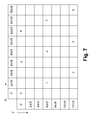
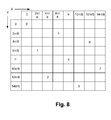
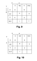
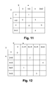
- the phase steps applied in this example form a checkerboard pattern in the x-y plane.
- phase steps are: ⁇ x : 0 , ⁇ / 2 , ⁇ , 3 ⁇ ⁇ / 2 , 0 , ⁇ / 2 , ⁇ , 3 ⁇ ⁇ / 2 ⁇ y : 0 , 3 ⁇ ⁇ / 2 , ⁇ , ⁇ / 2 , ⁇ , ⁇ / 2 , 0 , 3 ⁇ ⁇ / 2
- Step 640 checks if all 7 phase shifts are done.
- the phase steps applied in this example form a checkerboard pattern in the x-y plane.
- the phase steps are: ⁇ x : 0 , ⁇ / 2 , ⁇ , 3 ⁇ ⁇ / 2 , 0 , ⁇ / 2 , ⁇ ⁇ y : 0 , 3 ⁇ ⁇ / 2 , ⁇ , ⁇ / 2 , ⁇ ⁇ / 2 , 0
- Equation (11) the values of m x , m y , ⁇ x , ⁇ y can be deduced using Equation (11).
- Step 640 checks if all 6 phase shifts are done.
- the phase steps applied in this example form a checkerboard pattern in the x-y plane.
- the phase steps are: ⁇ x : 0 , ⁇ / 2 , ⁇ / 2 , ⁇ , ⁇ , 3 ⁇ ⁇ / 2 ⁇ y : ⁇ / 2 , 0 , ⁇ , ⁇ / 2 , 3 ⁇ ⁇ / 2 , ⁇
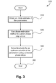
- the parameters in Equation (4) can also be estimated using an iterative method 200 shown in Fig. 2 which may also be implemented by the computer 1301. Referring to Fig. 2 , the method 200 commences with step 110 by which fringe pattern interferogram images are captured in the same way described in Fig. 1 . Step 220 then determines an estimate of the parameters in Equation (4) from an iterative solution.
- Step 130 solves for the x and y derivatives of the optical path length ⁇ ( x, y ) of the object in Fig. 4 , and the method 200 concludes at step 299.
- the reconstruction may be performed by treating the recovered data (recovered independently at each pixel) as images.
- the differential path length images are those that are commonly used as the features of the object are more visible once the carrier phase is removed.
- step 310 obtains an initial estimate of the phase and modulation parameters, a, m x , m y , ⁇ x and ⁇ y .
- the initial estimate of the five parameters can be the same as the first example, or it can be just random values, since the method to be implemented in this example is iterative.
- the parameter estimates for each pixel can be revised by generating an simulated (i.e. iterated) set of fringe intensities for that pixel and comparing the simulated set of fringe intensities with the set of captured fringe intensities at that pixel.
- Step 320 uses a phase estimation method to correct phase step errors.
- Step 330 solves iteratively for an optimum solution of the parameters using the corrected phase steps from step 320 and the initial estimate from 310.
- the value of M can be any integer greater than 4.
- the Gauss-Newton method updates the estimate of the parameter vector at each step until the estimate converges ( f ( C k ) ⁇ ⁇ , where ⁇ is some small number).
- Equation (28) the introduced phase steps ( ⁇ x,n , ⁇ y,n ) in Equation (28) are corrected in step 320 using a phase estimation method to reduce the error between the nominal phase steps and the actual phase steps in the experiments.
- any phase estimation method can be used to correct the phase steps ( ⁇ x,n , ⁇ y,n ) .
- the carrier frequency of each individual carrier in a group of phase-shifted images can be determined by measuring the position of the peaks in the Fourier transform, and the relative phases of each of the phase-shift images can be determined by measuring the complex phase of these peaks.
- Equation (28) the introduced phase steps ( ⁇ x,n , ⁇ y,n ) in Equation (28) are corrected in step 320 using a phase estimation method to reduce the error between the nominal phase steps and the actual phase steps in the experiments.
- a total of 7 images are captured in step 110. Similar to Example 7, Gauss-Newton algorithm is used to obtain an optimum estimate in the minimum mean square sense. This initial estimate C 0 for the iterative algorithm can be chosen heuristically. Unlike the closed-form solutions, as long as the Jacobian matrix J in Equation (28) is non-singular, no specific phase shift pattern is required.
- Equation (28) the introduced phase steps ( ⁇ x,n , ⁇ y,n ) in Equation (28) are corrected in step 320 using a phase estimation method to reduce the error between the nominal phase steps and the actual phase steps in the experiments.
- Equation (28) the introduced phase steps ( ⁇ x,n , ⁇ y,n ) in Equation (28) are corrected in step 320 using a phase estimation method to reduce the error between the nominal phase steps and the actual phase steps in the experiments.
- Step 640 checks if all 5 phase shifts are done. These 5 artificially introduced phase shifts are chosen to be some specific values to cover at least one cycle of a sinusoidal signal.
- n 0, ..., 4.
- Example 12 Non-linear demodulation with varying cross term
- z n a ( 1 + ⁇ x ⁇ cos ⁇ x , n + ⁇ x ⁇ sin ⁇ x , n + ⁇ y ⁇ cos ⁇ y , n + ⁇ y ⁇ sin ⁇ y , n + b ⁇ ⁇ x ⁇ ⁇ y ⁇ cos ⁇ y , n ⁇ cos ⁇ x , n + b ⁇ ⁇ x ⁇ ⁇ y ⁇ sin ⁇ y , n ⁇ sin ⁇ x , n + b ⁇ ⁇ x ⁇ ⁇ y ⁇ sin ⁇ y , n ⁇ cos ⁇ x , n + b ⁇ ⁇ x ⁇ ⁇ y ⁇ sin ⁇ y , n ⁇ cos ⁇ x , n + b ⁇ ⁇ x ⁇ ⁇ y ⁇ sin ⁇ y , n ⁇
- Gauss-Newton algorithm is used to obtain an optimum estimate in the minimum mean square sense.
- the initial estimate for the Gauss Newton algorithm can be chosen heuristically or the closed-form solutions described in Examples 1 - 5 can be used.
- the value of M can be any integer greater than 4.
- the value of M can be any integer greater than 4. This example demostrates that where the fringe pattern interferogram image comprises a crossed term varying in both dimensions, the amplitude of the crossed term can be estiomated independently using data about grating configuration, and the determined amplitude is used to revise the parameter estimates
- the examples provide processing of a number of moiré fringe pattern images obtained using a phase shifting technique for the estimation of the phase and modulation parameters, being an absorption parameter ( a ), amplitude modulation parameters (m x , m y ) and phase modulation parameters ( ⁇ x , ⁇ y ) caused by the object.
- These parameters are recovered independently for each pixel location in the image sequence and when considered as images and corrected for the carrier frequency of the moiré patterns according to equation (13) provide differential path length images ⁇ ⁇ ⁇ x ⁇ ⁇ ⁇ ⁇ y of the object (402,1324), potentially revealing detail of the object not otherwise discernible from the individual x-ray images or the fringe pattern images.
- the parameters each provide for corresponding representation by specific images.
- the specific images comprise:
- a reduction in the number of captured images is advantageous in that such reduces the exposure of the object (potentially a living organism) to X-ray radiation, and also reduces the collective data set that needs to be processed, thus generally reducing communication and computational time and costs.
- the specific images, and particularly the phase images may be used in isolation to reveal detail of the object not otherwise discernible from traditional x-ray methods, whilst the set of specific images may be used collectively for the full reconstruction of a phase image of the object.
- the images may be displayed on the display device 1314.
- the closed form approach can be used to derive a quick solution, but one that is subject to phase step errors.
- the iterative approach is significantly slower but by its very nature can accommodate phase step errors.
- the two approaches may be used in combination, where the closed form approach is initially used to quickly obtain a starting point for the iterative approach, which then provides a refined solution whilst avoiding unnecessary iterations. The result is an optimal set of specific images obtained using reasonable computing resources.
Landscapes
- Health & Medical Sciences (AREA)
- Chemical & Material Sciences (AREA)
- General Physics & Mathematics (AREA)
- Physics & Mathematics (AREA)
- Biochemistry (AREA)
- Pathology (AREA)
- Immunology (AREA)
- General Health & Medical Sciences (AREA)
- Life Sciences & Earth Sciences (AREA)
- Analytical Chemistry (AREA)
- Radiology & Medical Imaging (AREA)
- Nuclear Medicine, Radiotherapy & Molecular Imaging (AREA)
- Crystallography & Structural Chemistry (AREA)
- Engineering & Computer Science (AREA)
- Theoretical Computer Science (AREA)
- Apparatus For Radiation Diagnosis (AREA)
- Image Analysis (AREA)
- Image Processing (AREA)
Applications Claiming Priority (1)
| Application Number | Priority Date | Filing Date | Title |
|---|---|---|---|
| AU2012268876A AU2012268876A1 (en) | 2012-12-24 | 2012-12-24 | Non-linear solution for 2D phase shifting |
Publications (1)
| Publication Number | Publication Date |
|---|---|
| EP2746754A2 true EP2746754A2 (de) | 2014-06-25 |
Family
ID=50064346
Family Applications (1)
| Application Number | Title | Priority Date | Filing Date |
|---|---|---|---|
| EP13199391.7A Withdrawn EP2746754A2 (de) | 2012-12-24 | 2013-12-23 | Nichtlineare Lösung zur 2D-Phasenverschiebung |
Country Status (4)
| Country | Link |
|---|---|
| US (1) | US20140177790A1 (de) |
| EP (1) | EP2746754A2 (de) |
| JP (1) | JP5739976B2 (de) |
| AU (1) | AU2012268876A1 (de) |
Cited By (3)
| Publication number | Priority date | Publication date | Assignee | Title |
|---|---|---|---|---|
| WO2015038793A1 (en) * | 2013-09-12 | 2015-03-19 | The United States Of America, As Represented By The Secretary, Department Of Health & Human Services | Demodulation of intensity modulation in x-ray imaging |
| CN104501781A (zh) * | 2014-11-18 | 2015-04-08 | 中国科学院大学 | 基于已知先验信息约束的叠层成像技术 |
| CN105629695A (zh) * | 2016-01-13 | 2016-06-01 | 河北工程大学 | 一种基于相位层叠衍射的全息成像方法 |
Families Citing this family (9)
| Publication number | Priority date | Publication date | Assignee | Title |
|---|---|---|---|---|
| AU2013260650B2 (en) * | 2013-11-20 | 2015-07-16 | Canon Kabushiki Kaisha | Rotational phase unwrapping |
| JP2016106721A (ja) * | 2014-12-03 | 2016-06-20 | キヤノン株式会社 | 画像処理装置および画像処理方法 |
| JP6418066B2 (ja) | 2015-05-21 | 2018-11-07 | コニカミノルタ株式会社 | 位相画像処理方法、位相画像処理装置、画像処理装置及び画像処理プログラム |
| EP3314576B1 (de) * | 2015-06-26 | 2019-11-27 | Koninklijke Philips N.V. | Robuste rekonstruktion für dunkelfeld- und phasenkontrast-ct |
| CN106618623B (zh) * | 2017-01-11 | 2019-08-30 | 合肥工业大学 | 一次曝光的硬x射线光栅干涉仪的成像方法 |
| US10897560B2 (en) * | 2017-06-07 | 2021-01-19 | Rambus Inc. | Imaging devices and methods for reducing image artifacts |
| CN109186497B (zh) * | 2018-10-30 | 2019-11-26 | 北京理工大学 | 牛顿迭代的数字莫尔移相干涉法中频谱混叠噪声去除方法 |
| WO2020133531A1 (zh) * | 2018-12-29 | 2020-07-02 | 深圳大学 | X射线双相位光栅相衬成像系统 |
| JP7381827B2 (ja) * | 2019-05-30 | 2023-11-16 | 株式会社トプコン | 光干渉測定装置および光干渉測定方法 |
Family Cites Families (28)
| Publication number | Priority date | Publication date | Assignee | Title |
|---|---|---|---|---|
| US7341348B2 (en) * | 2003-03-25 | 2008-03-11 | Bausch & Lomb Incorporated | Moiré aberrometer |
| JP5174180B2 (ja) * | 2008-10-29 | 2013-04-03 | キヤノン株式会社 | X線撮像装置およびx線撮像方法 |
| DE102009004702B4 (de) * | 2009-01-15 | 2019-01-31 | Paul Scherer Institut | Anordnung und Verfahren zur projektiven und/oder tomographischen Phasenkontrastbildgebung mit Röntgenstrahlung |
| EP2443491B1 (de) * | 2009-06-16 | 2020-03-04 | Koninklijke Philips N.V. | Kippgitter und verfahren zur herstellung eines kippgitters |
| JP2011108696A (ja) * | 2009-11-13 | 2011-06-02 | Nikon Corp | 波面計測方法及び装置、並びに露光方法及び装置 |
| JP5789613B2 (ja) * | 2009-12-10 | 2015-10-07 | コーニンクレッカ フィリップス エヌ ヴェ | オンザフライ位相ステッピングを備えた非平行な格子装置、x線システム及び使用方法 |
| US8989474B2 (en) * | 2010-03-18 | 2015-03-24 | Konica Minolta Medical & Graphic, Inc. | X-ray image capturing system |
| JP2012090944A (ja) * | 2010-03-30 | 2012-05-17 | Fujifilm Corp | 放射線撮影システム及び放射線撮影方法 |
| JP2012090945A (ja) * | 2010-03-30 | 2012-05-17 | Fujifilm Corp | 放射線検出装置、放射線撮影装置、放射線撮影システム |
| DE102010017425A1 (de) * | 2010-06-17 | 2011-12-22 | Karlsruher Institut für Technologie | Geneigte Phasengitterstrukturen |
| CN103189739B (zh) * | 2010-10-19 | 2015-12-02 | 皇家飞利浦电子股份有限公司 | 微分相位对比成像 |
| JP5331940B2 (ja) * | 2010-10-27 | 2013-10-30 | 富士フイルム株式会社 | 放射線撮影システム及び放射線画像生成方法 |
| EP2633813B1 (de) * | 2010-10-29 | 2015-02-25 | FUJIFILM Corporation | Phasenkontrast-strahlungsabbildungsvorrichtung |
| JP2012115576A (ja) * | 2010-12-02 | 2012-06-21 | Fujifilm Corp | 放射線画像検出装置、放射線撮影装置、放射線撮影システム |
| JP2012143537A (ja) * | 2010-12-24 | 2012-08-02 | Fujifilm Corp | 放射線撮影システム及び画像処理方法 |
| JP5915645B2 (ja) * | 2011-03-23 | 2016-05-11 | コニカミノルタ株式会社 | 医用画像表示システム |
| JP2012200567A (ja) * | 2011-03-28 | 2012-10-22 | Fujifilm Corp | 放射線撮影システム及び放射線撮影方法 |
| JP5475925B2 (ja) * | 2011-04-20 | 2014-04-16 | 富士フイルム株式会社 | 放射線撮影装置及び画像処理方法 |
| JP2012236005A (ja) * | 2011-04-26 | 2012-12-06 | Fujifilm Corp | 放射線撮影装置 |
| JP2013063099A (ja) * | 2011-09-15 | 2013-04-11 | Canon Inc | X線撮像装置 |
| JP5475737B2 (ja) * | 2011-10-04 | 2014-04-16 | 富士フイルム株式会社 | 放射線撮影装置及び画像処理方法 |
| RU2624513C2 (ru) * | 2012-01-24 | 2017-07-04 | Конинклейке Филипс Н.В. | Мультинаправленная фазоконтрастная рентгеновская визуализация |
| JP5857800B2 (ja) * | 2012-03-01 | 2016-02-10 | コニカミノルタ株式会社 | 関節撮影装置及び撮影対象固定ユニット |
| JP2014090967A (ja) * | 2012-11-06 | 2014-05-19 | Canon Inc | X線撮像装置 |
| AU2012268882B2 (en) * | 2012-12-24 | 2015-07-09 | Canon Kabushiki Kaisha | Estimating phase for phase-stepping algorithms |
| US9439613B2 (en) * | 2013-02-12 | 2016-09-13 | The Johns Hopkins University | System and method for phase-contrast X-ray imaging |
| AU2013260650B2 (en) * | 2013-11-20 | 2015-07-16 | Canon Kabushiki Kaisha | Rotational phase unwrapping |
| AU2013273822A1 (en) * | 2013-12-23 | 2015-07-09 | Canon Kabushiki Kaisha | Modulation guided phase unwrapping |
-
2012
- 2012-12-24 AU AU2012268876A patent/AU2012268876A1/en not_active Abandoned
-
2013
- 2013-12-11 US US14/103,685 patent/US20140177790A1/en not_active Abandoned
- 2013-12-23 EP EP13199391.7A patent/EP2746754A2/de not_active Withdrawn
- 2013-12-24 JP JP2013266132A patent/JP5739976B2/ja not_active Expired - Fee Related
Non-Patent Citations (1)
| Title |
|---|
| None |
Cited By (5)
| Publication number | Priority date | Publication date | Assignee | Title |
|---|---|---|---|---|
| WO2015038793A1 (en) * | 2013-09-12 | 2015-03-19 | The United States Of America, As Represented By The Secretary, Department Of Health & Human Services | Demodulation of intensity modulation in x-ray imaging |
| US9939392B2 (en) | 2013-09-12 | 2018-04-10 | The United States Of America, As Represented By The Secretary, Department Of Health And Human Services | Demodulation of intensity modulation in X-ray imaging |
| CN104501781A (zh) * | 2014-11-18 | 2015-04-08 | 中国科学院大学 | 基于已知先验信息约束的叠层成像技术 |
| CN105629695A (zh) * | 2016-01-13 | 2016-06-01 | 河北工程大学 | 一种基于相位层叠衍射的全息成像方法 |
| CN105629695B (zh) * | 2016-01-13 | 2019-01-18 | 河北工程大学 | 一种基于相位层叠衍射的全息成像方法 |
Also Published As
| Publication number | Publication date |
|---|---|
| US20140177790A1 (en) | 2014-06-26 |
| AU2012268876A1 (en) | 2014-07-10 |
| JP5739976B2 (ja) | 2015-06-24 |
| JP2014121614A (ja) | 2014-07-03 |
Similar Documents
| Publication | Publication Date | Title |
|---|---|---|
| EP2746754A2 (de) | Nichtlineare Lösung zur 2D-Phasenverschiebung | |
| JP5766259B2 (ja) | 逆リース変換による差分画像の合成 | |
| Bruña et al. | Phase locking value revisited: teaching new tricks to an old dog | |
| Van Reeth et al. | Super‐resolution in magnetic resonance imaging: a review | |
| US20140369623A1 (en) | Estimating phase for phase-stepping algorithms | |
| Milanfar | A model of the effect of image motion in the Radon transform domain | |
| AU2013260650B2 (en) | Rotational phase unwrapping | |
| US9053542B2 (en) | Image resampling by frequency unwrapping | |
| CN106802137B (zh) | 一种相位展开方法及系统 | |
| Felsberg | Optical flow estimation from monogenic phase | |
| JP2016087473A (ja) | 2次元のフリンジ模様の復調において軸外周波数を低減するための非線形処理の方法、記憶媒体、および撮影システム | |
| JP2016077904A (ja) | 撮像方法、画像処理装置、コンピュータ可読媒体、方法、装置およびシステム | |
| Réthoré et al. | Curve and boundaries measurement using B-splines and virtual images | |
| Westin et al. | Three‐dimensional adaptive filtering in magnetic resonance angiography | |
| Qin et al. | Video superresolution reconstruction based on subpixel registration and iterative back projection | |
| Löcke et al. | A comparison of phase unwrapping methods in velocity‐encoded MRI for aortic flows | |
| US20090324012A1 (en) | System and method for contour tracking in cardiac phase contrast flow mr images | |
| Eklund et al. | True 4D image denoising on the GPU | |
| Tounsi et al. | Estimation of phase derivative from a single fringe pattern using Riesz transforms | |
| He et al. | Parallel Operator Splitting Algorithms with Application to Imaging Inverse Problems | |
| Li et al. | High precision and fast disparity estimation via parallel phase correlation hierarchical framework | |
| Frank et al. | Field dynamics inference via spectral density estimation | |
| Färneback et al. | Efficient computation of the inverse gradient on irregular domains | |
| Qazi et al. | Optimizing image reconstruction in SENSE using GPU | |
| Camara et al. | Multi-sequence registration of cine, tagged and delay-enhancement MRI with shift correction and steerable pyramid-based detagging |
Legal Events
| Date | Code | Title | Description |
|---|---|---|---|
| PUAI | Public reference made under article 153(3) epc to a published international application that has entered the european phase |
Free format text: ORIGINAL CODE: 0009012 |
|
| 17P | Request for examination filed |
Effective date: 20131223 |
|
| AK | Designated contracting states |
Kind code of ref document: A2 Designated state(s): AL AT BE BG CH CY CZ DE DK EE ES FI FR GB GR HR HU IE IS IT LI LT LU LV MC MK MT NL NO PL PT RO RS SE SI SK SM TR |
|
| AX | Request for extension of the european patent |
Extension state: BA ME |
|
| STAA | Information on the status of an ep patent application or granted ep patent |
Free format text: STATUS: THE APPLICATION HAS BEEN WITHDRAWN |
|
| 18W | Application withdrawn |
Effective date: 20170524 |