EP2744064B1 - Power supply device - Google Patents
Power supply device Download PDFInfo
- Publication number
- EP2744064B1 EP2744064B1 EP12822736.0A EP12822736A EP2744064B1 EP 2744064 B1 EP2744064 B1 EP 2744064B1 EP 12822736 A EP12822736 A EP 12822736A EP 2744064 B1 EP2744064 B1 EP 2744064B1
- Authority
- EP
- European Patent Office
- Prior art keywords
- power
- connector
- power source
- load
- loads
- Prior art date
- Legal status (The legal status is an assumption and is not a legal conclusion. Google has not performed a legal analysis and makes no representation as to the accuracy of the status listed.)
- Not-in-force
Links
Images


Classifications
-
- B—PERFORMING OPERATIONS; TRANSPORTING
- B60—VEHICLES IN GENERAL
- B60R—VEHICLES, VEHICLE FITTINGS, OR VEHICLE PARTS, NOT OTHERWISE PROVIDED FOR
- B60R16/00—Electric or fluid circuits specially adapted for vehicles and not otherwise provided for; Arrangement of elements of electric or fluid circuits specially adapted for vehicles and not otherwise provided for
- B60R16/02—Electric or fluid circuits specially adapted for vehicles and not otherwise provided for; Arrangement of elements of electric or fluid circuits specially adapted for vehicles and not otherwise provided for electric constitutive elements
- B60R16/03—Electric or fluid circuits specially adapted for vehicles and not otherwise provided for; Arrangement of elements of electric or fluid circuits specially adapted for vehicles and not otherwise provided for electric constitutive elements for supply of electrical power to vehicle subsystems or for
- B60R16/033—Electric or fluid circuits specially adapted for vehicles and not otherwise provided for; Arrangement of elements of electric or fluid circuits specially adapted for vehicles and not otherwise provided for electric constitutive elements for supply of electrical power to vehicle subsystems or for characterised by the use of electrical cells or batteries
-
- H—ELECTRICITY
- H02—GENERATION; CONVERSION OR DISTRIBUTION OF ELECTRIC POWER
- H02J—CIRCUIT ARRANGEMENTS OR SYSTEMS FOR SUPPLYING OR DISTRIBUTING ELECTRIC POWER; SYSTEMS FOR STORING ELECTRIC ENERGY
- H02J7/00—Circuit arrangements for charging or depolarising batteries or for supplying loads from batteries
- H02J7/14—Circuit arrangements for charging or depolarising batteries or for supplying loads from batteries for charging batteries from dynamo-electric generators driven at varying speed, e.g. on vehicle
-
- B—PERFORMING OPERATIONS; TRANSPORTING
- B60—VEHICLES IN GENERAL
- B60Q—ARRANGEMENT OF SIGNALLING OR LIGHTING DEVICES, THE MOUNTING OR SUPPORTING THEREOF OR CIRCUITS THEREFOR, FOR VEHICLES IN GENERAL
- B60Q1/00—Arrangement of optical signalling or lighting devices, the mounting or supporting thereof or circuits therefor
- B60Q1/0088—Details of electrical connections
- B60Q1/0094—Arrangement of electronic circuits separated from the light source, e.g. mounting of housings for starter circuits for discharge lamps
-
- H—ELECTRICITY
- H02—GENERATION; CONVERSION OR DISTRIBUTION OF ELECTRIC POWER
- H02J—CIRCUIT ARRANGEMENTS OR SYSTEMS FOR SUPPLYING OR DISTRIBUTING ELECTRIC POWER; SYSTEMS FOR STORING ELECTRIC ENERGY
- H02J2310/00—The network for supplying or distributing electric power characterised by its spatial reach or by the load
- H02J2310/40—The network being an on-board power network, i.e. within a vehicle
- H02J2310/46—The network being an on-board power network, i.e. within a vehicle for ICE-powered road vehicles
Definitions
- This invention relates to power supply units, particularly to power supply units including batteries and a plurality of loads receiving power from the batteries.
- Such a vehicle as an automobile has a power supply unit mounted therein for supplying power to a plurality of loads.
- a power supply unit is, for example, what is illustrated in FIG. 14 .
- the power supply unit 100 is provided with a battery 101, ramp loads 102 as a plurality of loads, and a controller 103 disposed between the battery 101 and the plurality of ramps 102.
- the aforementioned controller 103 is mounted to, for example, a power supply box disposed near the battery 101.
- This controller 103 incorporates a branch circuit 103a branching a power line form the battery 101 into a plurality of branch lines, and a plurality of switch elements 103b each disposed on the branch lines branched by the branch circuit 103a.
- a Mechanical relay or transistor relay is used as the switch elements 103b.
- the switch elements 103b is controlled to switch on or off by supplying a drive signal from a main drive device 200.
- to switch on the switch elements 103b by the main drive device 200 allows power from the battery 101 to be supplied to the ramp loads 102, and to switch off the switch elements 103b by the main drive device 200 allows power supplied from the battery 101 to the ramp loads 102 to be shut down.
- the automobile in order to charge the battery 101, also has alternate 104 mounted thereto as a generator transforming mechanical energy of an engine into an electric energy.
- this alternate 104 may be disposed between the battery 101 and the ramp loads 102.
- a DC/DC convertor 105 may be disposed between the battery 101 and the ramp loads 102 that steps down the power voltage from the battery 101.
- a cable L01 that connects between the battery 101 and the controller 103 is required to apply large current to which currents applied to the plurality of ramp loads 102 total up, and thus is applied for the one in which its cable size is large and pathway resistance is small.
- the cable L11 connecting the controller 103 and each ramp load 102 may apply current only applied to ramp loads 102 to be connected, and thus is applied for the one in which its cable size is small and pathway resistance is large.
- the aforementioned ramp loads 102 is regulated in its rated voltage, and when voltage beyond the rated voltage is applied, power the ramp loads 102 consume increases so as to become bright beyond necessity. It follows from this that applying voltage beyond the rated voltage to the ramp loads 102 results in applying useless voltage. Furthermore, the higher the voltage applied to the ramp loads 102, the more electrical stress applied to the ramp loads 102, possibly deteriorating product life (it is exactly well known that the ramp loads 102 such as filament when beyond the rated voltage becomes short in their product life).
- Reference EP 2 172 371 discloses a vehicle-mounted load controller which is characterized by including: a power terminal connected to a power line through a fuse; load connecting portions to which loads having vehicle-mounted light sources are connected; switches which are provided corresponding to the load connecting portions and which control states of power supply from the power line connected to the power terminal to the light sources connected to the load connecting portions; and a control unit which controls the switches in response to inputted control signals.
- the vehicle-mounted load controller is characterized in that the multiple load connecting portions to which the multiple light sources for different uses are respectively connected are electrically connected to the power terminal, and that each of the switches stops the supply of power from the power line to the light source connected to the corresponding load connecting portion when the magnitude of current flowing through the light source reaches or exceeds a predetermined value.
- a rise in lamp voltage during a period from the start of lighting to the establishment of stable lighting is reduced with consideration given to a history of lighting conditions for stable lighting. This produces effects such as increasing the lives of lamps and reducing the frequency of occurrence of arc jumping.
- the object of the invention is to provide a power supply unit capable of reducing deterioration of power loss caused by cable .
- the invention is set out in the first and the sixth embodiment.
- the other embodiments are examples that do not form part of the invention but represent background art that is useful for understanding the invention.
- the branch circuit since the branch circuit is located adjacent to the plurality of loads, it is made possible that the cable with large size and small pathway resistance between the power supply and the branch is enabled to be long, and the cable with small size and large pathway resistance between the branch and each load short, reducing deterioration of power loss caused by the cable.
- the branching circuit is housed in the connector housing, it is made possible to readily be attached to the power supply unit.
- the on/off controller intermittently switches on the switch elements and decreases the duty ratio of the on-period of the switching elements as the supply voltage detected by the voltage detector increases. Namely, the higher the supply voltage, the shorter the on-period of the switch elements, thus allowing power to be controlled in constant. This makes no useless power beyond certain level supplied, saving power and lengthening product life. Furthermore, enabling possibly shortening pathway between the connector and each load allows the supply voltage to be supplied to the loads to be accurately detected.
- This power supply unit 1 is the one that is mounted to an ICEC (Internal Combustion Engine Vehicle) .
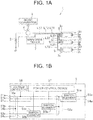
- the power supply unit 1 is provided with a battery 2 as a power source, a plurality of loads 31 to 33 receiving power supply from such the battery 2 to operate, an alternator 4 disposed between the battery 2 and the plurality of loads 31 to 33, a connector 5 connecting a power line L11 connected to the battery 2, ground line L12, and the plurality of loads 31 to 33.
- the aforementioned battery 2 uses what is called a secondary battery such as a lead battery or lithium battery, and is arranged within, e.g., an engine room in the vehicle.
- the plurality of loads units 31 to 33 is each provided with a ramp load 3a, a holder 3b holding and housing the ramp load 3a, and a connector 3c disposed integral with the holder 3b. These load units 31 to 33 are arranged near to each other in the vehicle.
- the aforementioned connector 3c is composed of, e.g., a not-shown male and female terminal fitting connected to both ends of the ramp load 3a, and a housing disposed integral with the holder 3b holding these terminal fittings.
- the alternator 4 is a generator that transforms mechanical energy from an engine into an electric energy, charging the battery 2 or supplying directly power to the aforementioned ramp load 3a. While instead of this alternator 4, DC/DC convertor 6 may be connected between the battery 2 and the plurality of load units 31 to 33 that steps down the supply voltage from the battery 2, the alternator 4 is herein described.
- the aforementioned connector 5 is connected and mounted to the connector 3c of the one load unit 31 among the plurality of load units 31 to 33.
- This load unit 31 is provided with the ramp load 3a of which consumption current is the largest among the ramp loads 3a disposed to the load units 31 to 33.
- This connector 5 initiates according to an output of a drive signal from a main drive device 7 supplying power to the ramp load 3a incorporated into the plurality of load units 31 to 33, and blocks according to stop of the output of the drive signal supplying power to the ramp load 3a.
- This connector 5 is, as shown in FIG. 1B , provided with a pressure-bonding power source terminal 51a, a pressure-bonding ground terminal 51b, a pressure-bonding terminal 51c, a first branch circuit 52a, a second branch circuit 52b, a tub-like power source terminal 53a, a pressure-bonding power source terminals 53b, 53c, a tub-like ground terminal 54a, and pressure-bonding ground terminals 54b, 54c.
- the pressure-bonding power source terminal 51a as the aforementioned first terminal fitting has the power source line L11 connected to a positive of the battery 2, connected thereto and a positive from the battery 2 is inputted.
- the pressure-bonding ground terminal 51b has the ground line L12 connected to a negative of the battery 2 connected and a negative from the battery 2 is inputted.
- the pressure-bonding signal terminal 51c has a signal line L13 connected to the main drive device 7, connected thereto and a drive signal is inputted.
- the first branch circuit 52a as the branch circuit is a circuit that branches one power source line inputted from the pressure-bonding power source terminal 51a into a plurality of branch lines.
- the aforementioned second branch circuit 52b is a circuit that branches one ground line inputted from the pressure-bonding ground terminal 51b into a plurality of branch lines.
- the tub-like power source terminal 53a, the pressure-bonding power source terminals 53b, 53c as the second terminal fittings are each connected to the plurality of branch lines branched by the first branch circuit 52a, and output the positive of the power source to each ramp loads 3a.
- the tub-like power source terminal 53a, the pressure-bonding power source terminals 53b, 53c are terminals that are each connected to the plurality of branch lines branched by the second branch circuit 52b, and output negative of the power source to each ramp load 3a.
- the aforementioned connector 5 is also provided with switch elements 55a to 55c each disposed on the branch line branched by the first branch circuit 52a, a voltage detector 56 detecting the input voltage V IN inputted from the pressure-bonding power source terminal 51a as power supply voltage supplied to the ramp load 3a disposed to each load units 31 to 33, and a power control device 57 as an on/off control means controlling on/off of the switch elements 55a to 55c in accordance with detecting result of the drive signal and the voltage detection device 56.
- the aforementioned switch elements 55a to 55c are made of, for example, semiconductor relay, when powered on, supplies power from the alternator 4 to the ramp load 3a, and when powered off, blocks power supply from the alternator 4 to the ramp load 3a.
- the aforementioned voltage detector 56 is made of, e.g., operational amplifier or the like, supplying a detected voltage to the power control device 57.
- the aforementioned power control device 57 is composed of, e.g., a known microprocessor or the like, managing wholly the power supply unit 1. These voltage detector 56 and the power control device 57 are those that receive power from the battery 2 through the pressure-bonding power source terminal 51a and the ground terminal 51b to operate.
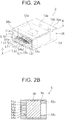
- the aforementioned connector 5 is also provided with a sealing body 58 where these terminals 51a to 51c, 53a to 53c, and 54a to 54c project, a housing 59 housing these terminals 51a to 51c, 53a to 53c, and 54a to 54c, and the sealing body 58.
- the aforementioned pressure-bonding power source terminal 51a, the pressure-bonding ground terminal 51b, the pressure-bonding signal terminal 51c, the pressure-bonding power source terminals 53b, 53c, and the pressure-bonding ground terminals 54b, 54c are mode of conductive metal, one end of which is each inserted into the sealing body 58 to be mentioned below, the other end of which each projects from one face of a pair of opposite faces of the sealing body 58.
- pressure-bonding power source terminal 51a, the pressure-bonding ground terminal 51b, the pressure-bonding signal terminal 51c, the pressure-bonding power source terminals 53b, 53c, and the pressure-bonding ground terminals 54b, 54c have pressure-bonding blade formed at the other end thereof.
- the pressure-bonding power source terminal 51a has a terminal of the power source line L11 pressure bonded, the pressure-bonding ground terminal 51b a terminal of the ground line L12, and the pressure-bonding signal terminal 51c a terminal of the signal line L13.
- the pressure-bonding power source terminal 53b, the pressure-bonding ground terminal 54b have one end of the power line L21 and one end of the ground line L22 connected to the load unit 33 as the power line pressure bonded.
- the pressure-bonding power source terminal 53c, the pressure-bonding ground terminal 54c have one end of the power line L31 and one end of the ground line L32 connected to the load unit 32 as the power line pressure bonded.
- the other ends of the aforementioned power source line L31 and the ground line L32 also have the connector 9 attached thereto, which the connector 9 is connected to the connector 3c of the load unit 32. Then, when the connector 9 and the connector 3c of the load unit 32 are connected, the power source L31 and the ground line L32 are connected to both ends of the ramp load 3a of the load unit 32.
- the aforementioned tub-like power source terminal 53a and the tub-like ground terminal 54a are made of conductive metal, one ends of which are inserted into the sealing body 58 to be mentioned below, the other ends of which each project from the other face of the pair of opposite faces of the sealing body 58.
- the other ends of the tub-like power source terminal 53a and the tub-like ground terminal 54a are formed into a tub-like shape, and are engaged with the female terminal fitting disposed to the connector 3c of the load unit 31.
- the sealing body 58 and the housing 59 are then discussed.
- the sealing body 58 seals with resin the aforementioned first branch circuit 52a, the second branch circuit 52b, the switch elements 55a to 55c, chip 58a having the voltage detector 56 and the power control device 57 mounted thereto, these terminals 51a to 51c, 53a to 53c, and 54a to 54c with their wire-bonded are sealed with resin.
- the aforementioned housing 59 houses these terminals 51a to 51c, 53a to 53c, and 54a to 54c, and the sealing body 58.
- the housing 59 is formed into a flattened square shape, and from an opening of one of the housing 59 the pressure-bonding power source terminal 51a, the pressure-bonding ground terminal 51b, the pressure-bonding signal terminal 51c, the pressure-bonding power source terminals 53b, 53c, and the pressure-bonding ground terminals 54b, 54c are exposed, from an opening of the other the tub-like power source terminal 53a and the tub-like ground terminal 54a are exposed.
- the other side of the housing 59 in a tubular length direction is provided with a hood 59a into which a housing for the connector 3c disposed to the load unit 31 is inserted to engage.
- the housing for the connector 3c disposed to the load unit 31 enters into the hood 59a, and thereby the terminal fitting of the connector 3c is connected to the tub-like power source terminal 53a and the tub-like ground terminal 54a.
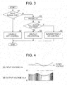
- FIG. 3 illustrates a flow chart of the power control device 57 composing the power supply unit 1 shown in FIG. 1 .
- FIG. 4 illustrates a time chart, of which (A) illustrates the input voltage V IN inputted from the pressure-bonding power source terminal 51a of the connector 5 composing the power supply unit 1 shown in FIG. 1 and of which (B) a time chart of the input voltage V OUT outputted from the tub-like power source terminal 53a, the pressure-bonding power source terminals 51b, 53c composing the power supply unit 1 shown in FIG. 1 .
- the power control device 57 also starts operation in accordance with the drive signal from the main drive device 7. Firstly, the power control device 57 determines whether the drive signal from the main drive device 7 is switched off or not (step S1) as shown in FIG. 3 . If switched off (Y in step S1), the power control device 57 stops outputting control signal to the switch elements 55a to 55a (step S2), before terminating. If not switched off (N in step S1), the power control device 57 otherwise goes to step S3.
- step S3 the power control device 57 imports the input voltage V IN detected by the voltage detector device 56. Then, the power control device 57 determines whether the voltage V IN imported in step S3 exceeds rated voltage (predetermined value) of the ramp load 3a preliminarily determined (step S4).
- the power control device 57 If the input voltage V IN does not exceed the rated voltage (N in step S4), the power control device 57 outputs control signal to usually switch on the switch elements 55a to 55c before terminating.
- step S6 the power control device 57 decreases duty ratio of on-period of the switch elements 55a to 55c as the input voltage V IN rises.
- the duty ratio of on-period is meant a ratio of on-period of the switch elements 55a to 55c divided by a cycle time of the switch elements 55a to 55c being switched on.
- the input voltage V IN bears a relationship with the power P OUT supplied to the ramp load 3a as shown in FIG. 5 .
- the switch elements 55a to 55c is controlled to be usually switched on by the power control device 57, resulting in power increasing as the input voltage V IN increase.
- the switch elements 55a to 55c is controlled to be intermittently switched on by the power control device 57, and on-period decreases as the input voltage V IN rises, making it possible to keep the power P OUT in constant.
- the aforementioned power supply unit 1 attaching the connector 5 integrating therein the circuit 52a to the holder 3b housing the plurality of ramp loads 3a, makes it possible to lengthen the power source line L11 that is thick and small pathway resistance between the battery 2 and the connector 5, and shorten the pathway that is thin and high pathway resistance to the ramp loads 3a disposed between the connector 5 and the load unit 31. Furthermore, since the load units 31 to 33 are arranged adjacent to each other, it is made possible to lengthen the power source lines L21, L31 that is thick and small pathway resistance to the ramp loads 3a disposed between the connector 5 and the load unit 32, 33. This makes possible reduction of power loss by the cables.
- the connector 5 is attached to the load unit 3a integrating the ramp load 3a of which consumption current is the largest, it is made possible to further reduce power loss.
- the power control device 57 controls to intermittently switch on the switch elements 55a to 55c and to decrease the duty ratio of on-period of the switch elements 55a to 55c as the input voltage V IN detected by the voltage detector 56 rises. Namely, the larger the input voltage V IN , the shorter the on-period of the switch elements 55a to 55c, making it possible to keep the power in constant. This attends not supplying useless power exceeding a certain level, making possible power saving and longer operating life. In addition, since as mentioned above it is made possible to possibly shorten pathway between the connector 5 and each ramp load 3a, it is made possible accurate detection for supply voltage supplied to the ramp load 3a.
- the power control device 57 controls to usually switch on the switch elements 55a to 55c while the input voltage V IN detected by the voltage detector 56 does not exceed the rated voltage, and controls to intermittently switch on the switch elements 55a to 55c while the input voltage V IN exceeds the rated voltage, it is made possible fulfilling function of the ramp load 3a.
- the alternator 4 or DC/DC convertor 6 connected in parallel to the battery 2 is further provided, and the switch elements 55a to 55c are disposed nearer to the ramp load 3a than the alternator 4 or DC/DC convertor 6. Therefore, with the alternator 4, reduction of engine load makes possible for power saving to improve by reduction of power generation torque of the alternator 4, contributing to reduction of consumption fuel. With the DC/DC convertor 6, reduction of the output voltage makes possible reduction of a consumption of battery 2.
- the invention is not limited to this embodiment.
- the ground voltage is supplied to the ramp load 3a via another route, the second branch circuit 52b, the tub-like ground terminal 54a, the pressure-bonding ground terminals 54a, 54c may not be provided.
- the ground voltage may be inputted from one of the plurality of ramp loads 3a.
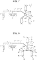
- the aforementioned connector 5 may be arranged nearer to the plurality of ramp loads 3a than the middle between the battery 2 and the plurality of ramp loads 3a, for example, as shown in FIG. 6 , the connector 5 and the load unit 31 may be connected with the power source line L41 and the ground line L41 as cables, so as to connect all the load units 31 and the connector 5 with cables.
- the power source terminal 53a and the ground terminal 54b are provided with not only a tub-like shape, but a pressure-bonding blade, and the power source line L41 and the ground line L41 are pressure-bonded.
- the connector 5 when each of the load units 31 to 33 are, for example, arranged as shown in FIG. 7 , the connector 5 is arranged in the middle of the load units 31 to 33 as shown in FIG. 7 , the connector 5 may be arranged within a range of the power lines L21, L31, L41, and the ground lines L22, L32, L42 being possibly wired, where total cable length of the plurality of power source lines L21, L31, L41, and the ground lines L22, L32, L42 becomes the shortest.
- the connector 5 is arranged in the middle of the load units 32 and 33 as shown in FIG. 8 , the connector 5 may be arranged within a range of the power lines L21, L31, L41, and the ground lines L22, L32, L42 being possibly wired, where total power loss the plurality of power source lines L21, L31, L41, and the ground lines L22, L32, L42 becomes minimum.
- the connector 5 may be arranged within a range of the power lines L21, L31, L41, and the ground lines L22, L32, L42 being possibly wired, where total weight of the plurality of power source lines L21, L31, L41, and the ground lines L22, L32, L42 becomes minimum.
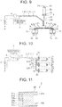
- FIG. 10 is the schematic diagram illustrating the sixth embodiment of the power supply unit 1 of the invention.
- FIG. 11 is the cross-sectional view of the connector 5 shown in FIG. 10 .
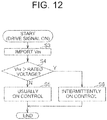
- FIG. 12 is the flow chart of the power control device composing the power supply unit 1 shown in FIG. 10 .
- on/off drive to the ramp load 3a and duty control in accordance with the input V IN is made by the connector 5
- this invention is not limited to this configuration.
- a switch element 8 may be arranged between the battery 2 or the alternator 4 and the connector 5, on/off drive to the ramp load 3a is made by the switch element 8, and the duty control is made by the connector 5.
- the aforementioned switch element 8 is, for example, composed of a mechanical relay, or a semiconductor relay, switches on in accordance with the output of the drive signal from the main drive device 7 so as to start supplying power to the voltage detector 56 and the power control device 57 integrated in the ramp load 3a or the connector 5, or block supplying power to the voltage detector 56 and the power control device 57 integrated in the ramp load 3a or the connector 5 in accordance with stop of the output of the drive signal from the main drive device 7.
- the power control device 57 is, differing from the first embodiment, not supplied with the drive signal. Therefore, differing from the first embodiment, the connector 5 is not provide with the pressure-bonding signal terminal 51c for inputting the drive signal as shown in FIG. 11 .
- the power control device 57 While in the first embodiment confirming a state of drive signal in the step S1, instantly goes to steps S3 to S6 without operation in the steps S1 and S2.
- the steps S3 to S6 were described in the aforementioned first embodiment, of which detailed description is thereby omitted herein.
- FIG. 10 illustrates an example to which the first embodiment is applied, but the second to the fifth embodiments can be applied thereto.
- the power control device 57 entirely controls the plurality of switch elements 55a to 55c, but the invention is not limited to this configuration. With the drive signal every ramp load 3a from the main drive device 7 outputting, or the rated voltage of the ramp load 3a differing, the plurality of switch elements 55a to 55c may be controlled independently from each other.
- the power control device 57 controls the duty ratio of each of the switch elements 55a to 55c, but the invention is not limited to this configuration.
- the power control device 57 may usually switch on the switch elements 55a to 55c only when the drive signal is supplied, and may usually switch off the switch elements 55a to 55c when the drive signal is not supplied.
- the connector 5 integrates therein the switch elements 55a to 55c, the voltage detector 56 and the power control device 57, but the invention is not limited to this configuration.
- the connector 5 may integrate therein at least the pressure-bonding power source terminal 51a, the first branch circuit 52a, the tub-like power source terminal 53a, but the switch elements 55a to 55c, the voltage detector 56, and the power control device 57 are not indispensable.
- the alternator 4 is disposed between embodiments the battery 2 and the ramp load 3a, but the invention is not limited to this configuration.
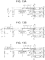
- the alternator 4 may be connected to the battery 2 in parallel, but such case can be applied thereto that any ICEV has the power supply unit 1 configured as shown in FIG. 13A .
- the terminals 51a to 51c, 53b, 53c, 54b, and 54c projecting from one side of the connector 5 have pressure-bonding blade formed, the terminals 53a and 54a projecting from the other side have pressure-bonding blade formed into tub-like shape, but forms of the terminal 51a to 51c, 53a to 53c, and 54a to 54c are not limited to this configuration.
- the load is described taking the ramp load 3a, but the invention is not limited to this configuration.
- Such load may be driven receiving power supply from the battery, as other motors as well.
- DC/DC convertor 6 is disposed between the battery 2 and the ramp load 3a, but the invention is not limited to this configuration.
- the DC/DC convertor 6 may be connected in parallel to the battery 2, which can also be applied to HEV (Hybrid Electric Vehicle) or PHEV (Plug-In Hybrid Electric Vehicle) having power source device 1 mounted therein provided with two batteries 2, 11 and generator 10.
- HEV Hybrid Electric Vehicle
- PHEV Plug-In Hybrid Electric Vehicle
- BEV Battery Electric Vehicle
- FCEV Full Cell Electric Vehicle
- FIG. 13 illustrates an example to which the first embodiment is applied, but to which the second to sixth embodiments can be applied.
- the first branch circuit 52a is integrated into the connector 5, but the invention is not limited to this configuration.
- the connector 5 may not be integrated thereinto.
Landscapes
- Engineering & Computer Science (AREA)
- Power Engineering (AREA)
- Mechanical Engineering (AREA)
- Direct Current Feeding And Distribution (AREA)
- Charge And Discharge Circuits For Batteries Or The Like (AREA)
- Secondary Cells (AREA)
- Circuit Arrangement For Electric Light Sources In General (AREA)
Applications Claiming Priority (2)
| Application Number | Priority Date | Filing Date | Title |
|---|---|---|---|
| JP2011175840A JP5892533B2 (ja) | 2011-08-11 | 2011-08-11 | 電源供給装置 |
| PCT/JP2012/069797 WO2013021928A1 (ja) | 2011-08-11 | 2012-08-03 | 電源供給装置 |
Publications (3)
| Publication Number | Publication Date |
|---|---|
| EP2744064A1 EP2744064A1 (en) | 2014-06-18 |
| EP2744064A4 EP2744064A4 (en) | 2015-11-25 |
| EP2744064B1 true EP2744064B1 (en) | 2018-07-25 |
Family
ID=47668436
Family Applications (1)
| Application Number | Title | Priority Date | Filing Date |
|---|---|---|---|
| EP12822736.0A Not-in-force EP2744064B1 (en) | 2011-08-11 | 2012-08-03 | Power supply device |
Country Status (5)
| Country | Link |
|---|---|
| US (1) | US9545889B2 (enExample) |
| EP (1) | EP2744064B1 (enExample) |
| JP (1) | JP5892533B2 (enExample) |
| CN (1) | CN103875152A (enExample) |
| WO (1) | WO2013021928A1 (enExample) |
Families Citing this family (11)
| Publication number | Priority date | Publication date | Assignee | Title |
|---|---|---|---|---|
| CN105656096A (zh) * | 2014-11-14 | 2016-06-08 | 江苏永昌新能源科技有限公司 | 一种电动车锂电池安装壳 |
| FR3041579B1 (fr) * | 2015-09-24 | 2017-10-13 | Vignal Systems | Feu arriere de vehicule et systeme de commande d’un accessoire d’un vehicule |
| CN106593148B (zh) * | 2015-10-16 | 2019-04-05 | 联合汽车电子有限公司 | 乘用车门锁控制单元 |
| JP6387040B2 (ja) | 2016-04-28 | 2018-09-05 | 矢崎総業株式会社 | 車両電源制御装置 |
| JP6646540B2 (ja) | 2016-07-13 | 2020-02-14 | 矢崎総業株式会社 | 車両電源制御装置 |
| JP6836414B2 (ja) | 2017-02-09 | 2021-03-03 | 矢崎総業株式会社 | 車両電源制御装置 |
| JP2018127148A (ja) | 2017-02-09 | 2018-08-16 | 矢崎総業株式会社 | 車両電源制御装置 |
| JP6836925B2 (ja) | 2017-02-09 | 2021-03-03 | 矢崎総業株式会社 | 車両電源制御装置 |
| JP7140725B2 (ja) * | 2019-07-31 | 2022-09-21 | 本田技研工業株式会社 | 電源装置 |
| EP3786649A1 (de) * | 2019-08-29 | 2021-03-03 | Siemens Aktiengesellschaft | Verfahren zum überprüfen von lastkreisen in einer technischen anlage |
| KR102512377B1 (ko) * | 2021-08-10 | 2023-03-21 | 현대모비스 주식회사 | 엘이디 드라이버 모듈 및 이를 포함하는 차량 |
Citations (1)
| Publication number | Priority date | Publication date | Assignee | Title |
|---|---|---|---|---|
| JP2004259582A (ja) * | 2003-02-26 | 2004-09-16 | Yazaki Corp | ランプ制御回路、およびランプ制御方法 |
Family Cites Families (19)
| Publication number | Priority date | Publication date | Assignee | Title |
|---|---|---|---|---|
| JPS54159934A (en) * | 1978-06-09 | 1979-12-18 | Yazaki Corp | Wireering system of automobile |
| JPS5780681A (en) * | 1980-11-10 | 1982-05-20 | Hitachi Ltd | Concentrated wiring device for vehicle |
| GB9406625D0 (en) * | 1994-04-05 | 1994-05-25 | Smiths Industries Plc | Electrical systems and connectors |
| EP0692850B1 (en) * | 1994-07-15 | 2003-03-12 | Sumitomo Wiring Systems, Ltd. | Electrical connection box |
| US5604385A (en) * | 1995-05-22 | 1997-02-18 | Target Hi-Tech Electronics Ltd. | Apparatus for and method of evenly distributing an electrical load across a three phase power distribution network |
| US6144110A (en) * | 1997-03-19 | 2000-11-07 | The Furukawa Electric Co., Ltd. | Vehicular use power distribution apparatus and vehicular use power source apparatus |
| DE19739410C1 (de) * | 1997-08-28 | 1998-12-17 | Volkswagen Bordnetze Gmbh | Elektrische Schaltungsanordnung für das Bordnetz eines Kraftfahrzeuges |
| JP2002200948A (ja) * | 2000-12-28 | 2002-07-16 | Denso Corp | 車両用配電装置 |
| JP3713477B2 (ja) * | 2001-11-19 | 2005-11-09 | Tdk株式会社 | 電力線通信システム |
| JP2003212065A (ja) * | 2002-01-24 | 2003-07-30 | Yazaki Corp | 電力供給装置及びジョイントコネクタ |
| JP3794564B2 (ja) * | 2002-02-08 | 2006-07-05 | 古河電気工業株式会社 | 電源制御装置 |
| US6972375B2 (en) * | 2002-10-21 | 2005-12-06 | Denso Corporation | Wiring harness |
| US6768647B1 (en) * | 2003-03-19 | 2004-07-27 | Lear Corporation | Wireless RF/serial remote zone connector and system |
| DE10341838A1 (de) * | 2003-09-09 | 2005-04-28 | Siemens Ag | Verfahren zur Steuerung von Energieströmen |
| JP2005297860A (ja) * | 2004-04-14 | 2005-10-27 | Toyota Motor Corp | 車両用電源装置 |
| JP2008298536A (ja) | 2007-05-30 | 2008-12-11 | Canon Inc | 接続検知装置 |
| JP5144160B2 (ja) * | 2007-07-26 | 2013-02-13 | パナソニック株式会社 | 車載用負荷制御装置、車載用前照灯装置、および車載用尾灯装置 |
| JP5170888B2 (ja) * | 2008-08-01 | 2013-03-27 | 古河電気工業株式会社 | 車両用電源供給装置及び車両用電源供給方法 |
| JP2010192240A (ja) * | 2009-02-18 | 2010-09-02 | Sumitomo Wiring Syst Ltd | 半導体リレーモジュール付ワイヤハーネス |
-
2011
- 2011-08-11 JP JP2011175840A patent/JP5892533B2/ja not_active Expired - Fee Related
-
2012
- 2012-08-03 WO PCT/JP2012/069797 patent/WO2013021928A1/ja not_active Ceased
- 2012-08-03 EP EP12822736.0A patent/EP2744064B1/en not_active Not-in-force
- 2012-08-03 CN CN201280049906.1A patent/CN103875152A/zh active Pending
-
2014
- 2014-02-11 US US14/177,701 patent/US9545889B2/en not_active Expired - Fee Related
Patent Citations (1)
| Publication number | Priority date | Publication date | Assignee | Title |
|---|---|---|---|---|
| JP2004259582A (ja) * | 2003-02-26 | 2004-09-16 | Yazaki Corp | ランプ制御回路、およびランプ制御方法 |
Also Published As
| Publication number | Publication date |
|---|---|
| JP5892533B2 (ja) | 2016-03-23 |
| EP2744064A4 (en) | 2015-11-25 |
| US9545889B2 (en) | 2017-01-17 |
| CN103875152A (zh) | 2014-06-18 |
| WO2013021928A1 (ja) | 2013-02-14 |
| US20140159482A1 (en) | 2014-06-12 |
| JP2013042563A (ja) | 2013-02-28 |
| EP2744064A1 (en) | 2014-06-18 |
Similar Documents
| Publication | Publication Date | Title |
|---|---|---|
| EP2744064B1 (en) | Power supply device | |
| US10710469B2 (en) | Automotive dual voltage battery charging system | |
| KR101866037B1 (ko) | 차량의 배터리 관리 시스템 | |
| US11535151B2 (en) | Vehicle and method of notifying charging information of vehicle | |
| US9731610B2 (en) | Vehicle electric system, device for controlling a vehicle electric system, and vehicle with a device | |
| KR102478091B1 (ko) | 차량용 배터리 충전 제어 시스템 및 방법 | |
| US11843274B2 (en) | Charge control apparatus for controlling charging of an energy storage device via purality of charging paths connected in parallel anssociated energy storage appartus, and an associated charging method | |
| JP2018125947A (ja) | 電源システム | |
| KR20180045954A (ko) | 배터리 관리 시스템 및 그 제어방법 | |
| CN105984353A (zh) | 电池电源整合装置以及具有该装置的油电混合车电源系统 | |
| KR20120062956A (ko) | 전기 자동차의 고전압 시스템 | |
| JP2004519593A (ja) | 車両の多電圧電源回路網へのエネルギ供給装置 | |
| US20130249522A1 (en) | Power Supply Control Device | |
| JP7200902B2 (ja) | 電動車両の電源回路 | |
| CN110450675B (zh) | 一种动力电池系统、控制方法和电动汽车 | |
| JP2015226360A (ja) | 車載用dcdcコンバータ | |
| EP2045902A1 (en) | Power supply device | |
| KR20170000325U (ko) | 전기자동차의 배터리 디스커넥트 유닛용 일체형 프리차지 릴레이 | |
| KR102171985B1 (ko) | 친환경 차량의 비상 전력 공급 장치 | |
| WO2003067737A1 (en) | Method of automotive battery charging | |
| JP7575434B2 (ja) | 車両用電源制御システム | |
| JP2007020283A (ja) | 車両用電源制御システム | |
| JP2024068962A (ja) | 電源制御装置及び電源制御システム | |
| KR20240121618A (ko) | 차량 충전 장치 |
Legal Events
| Date | Code | Title | Description |
|---|---|---|---|
| PUAI | Public reference made under article 153(3) epc to a published international application that has entered the european phase |
Free format text: ORIGINAL CODE: 0009012 |
|
| 17P | Request for examination filed |
Effective date: 20140305 |
|
| AK | Designated contracting states |
Kind code of ref document: A1 Designated state(s): AL AT BE BG CH CY CZ DE DK EE ES FI FR GB GR HR HU IE IS IT LI LT LU LV MC MK MT NL NO PL PT RO RS SE SI SK SM TR |
|
| DAX | Request for extension of the european patent (deleted) | ||
| RA4 | Supplementary search report drawn up and despatched (corrected) |
Effective date: 20151023 |
|
| RIC1 | Information provided on ipc code assigned before grant |
Ipc: B60Q 1/00 20060101ALI20151019BHEP Ipc: H02J 7/00 20060101AFI20151019BHEP Ipc: B60R 16/02 20060101ALI20151019BHEP |
|
| 17Q | First examination report despatched |
Effective date: 20160808 |
|
| GRAP | Despatch of communication of intention to grant a patent |
Free format text: ORIGINAL CODE: EPIDOSNIGR1 |
|
| INTG | Intention to grant announced |
Effective date: 20180329 |
|
| GRAS | Grant fee paid |
Free format text: ORIGINAL CODE: EPIDOSNIGR3 |
|
| GRAA | (expected) grant |
Free format text: ORIGINAL CODE: 0009210 |
|
| AK | Designated contracting states |
Kind code of ref document: B1 Designated state(s): AL AT BE BG CH CY CZ DE DK EE ES FI FR GB GR HR HU IE IS IT LI LT LU LV MC MK MT NL NO PL PT RO RS SE SI SK SM TR |
|
| REG | Reference to a national code |
Ref country code: GB Ref legal event code: FG4D |
|
| REG | Reference to a national code |
Ref country code: CH Ref legal event code: EP |
|
| REG | Reference to a national code |
Ref country code: AT Ref legal event code: REF Ref document number: 1022801 Country of ref document: AT Kind code of ref document: T Effective date: 20180815 |
|
| REG | Reference to a national code |
Ref country code: IE Ref legal event code: FG4D |
|
| REG | Reference to a national code |
Ref country code: DE Ref legal event code: R096 Ref document number: 602012048954 Country of ref document: DE |
|
| REG | Reference to a national code |
Ref country code: NL Ref legal event code: MP Effective date: 20180725 |
|
| REG | Reference to a national code |
Ref country code: LT Ref legal event code: MG4D |
|
| PG25 | Lapsed in a contracting state [announced via postgrant information from national office to epo] |
Ref country code: NL Free format text: LAPSE BECAUSE OF FAILURE TO SUBMIT A TRANSLATION OF THE DESCRIPTION OR TO PAY THE FEE WITHIN THE PRESCRIBED TIME-LIMIT Effective date: 20180725 |
|
| REG | Reference to a national code |
Ref country code: AT Ref legal event code: MK05 Ref document number: 1022801 Country of ref document: AT Kind code of ref document: T Effective date: 20180725 |
|
| PG25 | Lapsed in a contracting state [announced via postgrant information from national office to epo] |
Ref country code: GR Free format text: LAPSE BECAUSE OF FAILURE TO SUBMIT A TRANSLATION OF THE DESCRIPTION OR TO PAY THE FEE WITHIN THE PRESCRIBED TIME-LIMIT Effective date: 20181026 Ref country code: NO Free format text: LAPSE BECAUSE OF FAILURE TO SUBMIT A TRANSLATION OF THE DESCRIPTION OR TO PAY THE FEE WITHIN THE PRESCRIBED TIME-LIMIT Effective date: 20181025 Ref country code: BG Free format text: LAPSE BECAUSE OF FAILURE TO SUBMIT A TRANSLATION OF THE DESCRIPTION OR TO PAY THE FEE WITHIN THE PRESCRIBED TIME-LIMIT Effective date: 20181025 Ref country code: AT Free format text: LAPSE BECAUSE OF FAILURE TO SUBMIT A TRANSLATION OF THE DESCRIPTION OR TO PAY THE FEE WITHIN THE PRESCRIBED TIME-LIMIT Effective date: 20180725 Ref country code: LT Free format text: LAPSE BECAUSE OF FAILURE TO SUBMIT A TRANSLATION OF THE DESCRIPTION OR TO PAY THE FEE WITHIN THE PRESCRIBED TIME-LIMIT Effective date: 20180725 Ref country code: PL Free format text: LAPSE BECAUSE OF FAILURE TO SUBMIT A TRANSLATION OF THE DESCRIPTION OR TO PAY THE FEE WITHIN THE PRESCRIBED TIME-LIMIT Effective date: 20180725 Ref country code: IS Free format text: LAPSE BECAUSE OF FAILURE TO SUBMIT A TRANSLATION OF THE DESCRIPTION OR TO PAY THE FEE WITHIN THE PRESCRIBED TIME-LIMIT Effective date: 20181125 Ref country code: RS Free format text: LAPSE BECAUSE OF FAILURE TO SUBMIT A TRANSLATION OF THE DESCRIPTION OR TO PAY THE FEE WITHIN THE PRESCRIBED TIME-LIMIT Effective date: 20180725 Ref country code: FI Free format text: LAPSE BECAUSE OF FAILURE TO SUBMIT A TRANSLATION OF THE DESCRIPTION OR TO PAY THE FEE WITHIN THE PRESCRIBED TIME-LIMIT Effective date: 20180725 Ref country code: SE Free format text: LAPSE BECAUSE OF FAILURE TO SUBMIT A TRANSLATION OF THE DESCRIPTION OR TO PAY THE FEE WITHIN THE PRESCRIBED TIME-LIMIT Effective date: 20180725 |
|
| PG25 | Lapsed in a contracting state [announced via postgrant information from national office to epo] |
Ref country code: AL Free format text: LAPSE BECAUSE OF FAILURE TO SUBMIT A TRANSLATION OF THE DESCRIPTION OR TO PAY THE FEE WITHIN THE PRESCRIBED TIME-LIMIT Effective date: 20180725 Ref country code: HR Free format text: LAPSE BECAUSE OF FAILURE TO SUBMIT A TRANSLATION OF THE DESCRIPTION OR TO PAY THE FEE WITHIN THE PRESCRIBED TIME-LIMIT Effective date: 20180725 Ref country code: LV Free format text: LAPSE BECAUSE OF FAILURE TO SUBMIT A TRANSLATION OF THE DESCRIPTION OR TO PAY THE FEE WITHIN THE PRESCRIBED TIME-LIMIT Effective date: 20180725 |
|
| REG | Reference to a national code |
Ref country code: CH Ref legal event code: PL |
|
| REG | Reference to a national code |
Ref country code: DE Ref legal event code: R097 Ref document number: 602012048954 Country of ref document: DE |
|
| PG25 | Lapsed in a contracting state [announced via postgrant information from national office to epo] |
Ref country code: LI Free format text: LAPSE BECAUSE OF NON-PAYMENT OF DUE FEES Effective date: 20180831 Ref country code: EE Free format text: LAPSE BECAUSE OF FAILURE TO SUBMIT A TRANSLATION OF THE DESCRIPTION OR TO PAY THE FEE WITHIN THE PRESCRIBED TIME-LIMIT Effective date: 20180725 Ref country code: LU Free format text: LAPSE BECAUSE OF NON-PAYMENT OF DUE FEES Effective date: 20180803 Ref country code: MC Free format text: LAPSE BECAUSE OF FAILURE TO SUBMIT A TRANSLATION OF THE DESCRIPTION OR TO PAY THE FEE WITHIN THE PRESCRIBED TIME-LIMIT Effective date: 20180725 Ref country code: CZ Free format text: LAPSE BECAUSE OF FAILURE TO SUBMIT A TRANSLATION OF THE DESCRIPTION OR TO PAY THE FEE WITHIN THE PRESCRIBED TIME-LIMIT Effective date: 20180725 Ref country code: IT Free format text: LAPSE BECAUSE OF FAILURE TO SUBMIT A TRANSLATION OF THE DESCRIPTION OR TO PAY THE FEE WITHIN THE PRESCRIBED TIME-LIMIT Effective date: 20180725 Ref country code: CH Free format text: LAPSE BECAUSE OF NON-PAYMENT OF DUE FEES Effective date: 20180831 Ref country code: ES Free format text: LAPSE BECAUSE OF FAILURE TO SUBMIT A TRANSLATION OF THE DESCRIPTION OR TO PAY THE FEE WITHIN THE PRESCRIBED TIME-LIMIT Effective date: 20180725 Ref country code: RO Free format text: LAPSE BECAUSE OF FAILURE TO SUBMIT A TRANSLATION OF THE DESCRIPTION OR TO PAY THE FEE WITHIN THE PRESCRIBED TIME-LIMIT Effective date: 20180725 |
|
| REG | Reference to a national code |
Ref country code: BE Ref legal event code: MM Effective date: 20180831 |
|
| REG | Reference to a national code |
Ref country code: IE Ref legal event code: MM4A |
|
| PG25 | Lapsed in a contracting state [announced via postgrant information from national office to epo] |
Ref country code: SM Free format text: LAPSE BECAUSE OF FAILURE TO SUBMIT A TRANSLATION OF THE DESCRIPTION OR TO PAY THE FEE WITHIN THE PRESCRIBED TIME-LIMIT Effective date: 20180725 Ref country code: DK Free format text: LAPSE BECAUSE OF FAILURE TO SUBMIT A TRANSLATION OF THE DESCRIPTION OR TO PAY THE FEE WITHIN THE PRESCRIBED TIME-LIMIT Effective date: 20180725 Ref country code: SK Free format text: LAPSE BECAUSE OF FAILURE TO SUBMIT A TRANSLATION OF THE DESCRIPTION OR TO PAY THE FEE WITHIN THE PRESCRIBED TIME-LIMIT Effective date: 20180725 |
|
| PLBE | No opposition filed within time limit |
Free format text: ORIGINAL CODE: 0009261 |
|
| STAA | Information on the status of an ep patent application or granted ep patent |
Free format text: STATUS: NO OPPOSITION FILED WITHIN TIME LIMIT |
|
| GBPC | Gb: european patent ceased through non-payment of renewal fee |
Effective date: 20181025 |
|
| 26N | No opposition filed |
Effective date: 20190426 |
|
| PG25 | Lapsed in a contracting state [announced via postgrant information from national office to epo] |
Ref country code: IE Free format text: LAPSE BECAUSE OF NON-PAYMENT OF DUE FEES Effective date: 20180803 |
|
| PG25 | Lapsed in a contracting state [announced via postgrant information from national office to epo] |
Ref country code: BE Free format text: LAPSE BECAUSE OF NON-PAYMENT OF DUE FEES Effective date: 20180831 Ref country code: FR Free format text: LAPSE BECAUSE OF NON-PAYMENT OF DUE FEES Effective date: 20180925 Ref country code: SI Free format text: LAPSE BECAUSE OF FAILURE TO SUBMIT A TRANSLATION OF THE DESCRIPTION OR TO PAY THE FEE WITHIN THE PRESCRIBED TIME-LIMIT Effective date: 20180725 |
|
| PG25 | Lapsed in a contracting state [announced via postgrant information from national office to epo] |
Ref country code: GB Free format text: LAPSE BECAUSE OF NON-PAYMENT OF DUE FEES Effective date: 20181025 |
|
| PG25 | Lapsed in a contracting state [announced via postgrant information from national office to epo] |
Ref country code: MT Free format text: LAPSE BECAUSE OF NON-PAYMENT OF DUE FEES Effective date: 20180803 |
|
| PG25 | Lapsed in a contracting state [announced via postgrant information from national office to epo] |
Ref country code: TR Free format text: LAPSE BECAUSE OF FAILURE TO SUBMIT A TRANSLATION OF THE DESCRIPTION OR TO PAY THE FEE WITHIN THE PRESCRIBED TIME-LIMIT Effective date: 20180725 |
|
| PG25 | Lapsed in a contracting state [announced via postgrant information from national office to epo] |
Ref country code: HU Free format text: LAPSE BECAUSE OF FAILURE TO SUBMIT A TRANSLATION OF THE DESCRIPTION OR TO PAY THE FEE WITHIN THE PRESCRIBED TIME-LIMIT; INVALID AB INITIO Effective date: 20120803 Ref country code: PT Free format text: LAPSE BECAUSE OF FAILURE TO SUBMIT A TRANSLATION OF THE DESCRIPTION OR TO PAY THE FEE WITHIN THE PRESCRIBED TIME-LIMIT Effective date: 20180725 |
|
| PG25 | Lapsed in a contracting state [announced via postgrant information from national office to epo] |
Ref country code: CY Free format text: LAPSE BECAUSE OF FAILURE TO SUBMIT A TRANSLATION OF THE DESCRIPTION OR TO PAY THE FEE WITHIN THE PRESCRIBED TIME-LIMIT Effective date: 20180725 Ref country code: MK Free format text: LAPSE BECAUSE OF NON-PAYMENT OF DUE FEES Effective date: 20180725 |
|
| PGFP | Annual fee paid to national office [announced via postgrant information from national office to epo] |
Ref country code: DE Payment date: 20230627 Year of fee payment: 12 |
|
| REG | Reference to a national code |
Ref country code: DE Ref legal event code: R119 Ref document number: 602012048954 Country of ref document: DE |
|
| PG25 | Lapsed in a contracting state [announced via postgrant information from national office to epo] |
Ref country code: DE Free format text: LAPSE BECAUSE OF NON-PAYMENT OF DUE FEES Effective date: 20250301 |