EP2743540A1 - Umschaltbares Motorlager - Google Patents
Umschaltbares Motorlager Download PDFInfo
- Publication number
- EP2743540A1 EP2743540A1 EP12008337.3A EP12008337A EP2743540A1 EP 2743540 A1 EP2743540 A1 EP 2743540A1 EP 12008337 A EP12008337 A EP 12008337A EP 2743540 A1 EP2743540 A1 EP 2743540A1
- Authority
- EP
- European Patent Office
- Prior art keywords
- engine mount
- mount according
- opening
- closure plug
- reversible
- Prior art date
- Legal status (The legal status is an assumption and is not a legal conclusion. Google has not performed a legal analysis and makes no representation as to the accuracy of the status listed.)
- Granted
Links
- 238000005192 partition Methods 0.000 claims abstract description 13
- 238000013016 damping Methods 0.000 claims abstract description 12
- 239000007788 liquid Substances 0.000 claims description 17
- 230000002441 reversible effect Effects 0.000 claims description 14
- 239000013536 elastomeric material Substances 0.000 claims description 3
- 239000012530 fluid Substances 0.000 abstract description 2
- 238000005096 rolling process Methods 0.000 description 6
- 230000010355 oscillation Effects 0.000 description 3
- 239000011324 bead Substances 0.000 description 2
- 239000012528 membrane Substances 0.000 description 2
- 239000006096 absorbing agent Substances 0.000 description 1
- 230000001419 dependent effect Effects 0.000 description 1
- 238000011161 development Methods 0.000 description 1
- 230000018109 developmental process Effects 0.000 description 1
- 238000002955 isolation Methods 0.000 description 1
Images



Classifications
-
- F—MECHANICAL ENGINEERING; LIGHTING; HEATING; WEAPONS; BLASTING
- F16—ENGINEERING ELEMENTS AND UNITS; GENERAL MEASURES FOR PRODUCING AND MAINTAINING EFFECTIVE FUNCTIONING OF MACHINES OR INSTALLATIONS; THERMAL INSULATION IN GENERAL
- F16F—SPRINGS; SHOCK-ABSORBERS; MEANS FOR DAMPING VIBRATION
- F16F13/00—Units comprising springs of the non-fluid type as well as vibration-dampers, shock-absorbers, or fluid springs
- F16F13/04—Units comprising springs of the non-fluid type as well as vibration-dampers, shock-absorbers, or fluid springs comprising both a plastics spring and a damper, e.g. a friction damper
- F16F13/26—Units comprising springs of the non-fluid type as well as vibration-dampers, shock-absorbers, or fluid springs comprising both a plastics spring and a damper, e.g. a friction damper characterised by adjusting or regulating devices responsive to exterior conditions
- F16F13/262—Units comprising springs of the non-fluid type as well as vibration-dampers, shock-absorbers, or fluid springs comprising both a plastics spring and a damper, e.g. a friction damper characterised by adjusting or regulating devices responsive to exterior conditions changing geometry of passages between working and equilibration chambers, e.g. cross-sectional area or length
Definitions
- the present invention relates to a switchable motor bearing of a support bearing and a support, which are interconnected by an elastomeric spring body and having a working space and a compensation space, which separated by a partition, filled with a liquid and hydraulically connected to each other via a damping channel are, wherein the partition has a closable via a switch opening.
- Reversible bearings of this type are known per se and are manufactured in multiple designs. Individual parts of the warehouse take on assigned functions. Turning certain parts on or off changes the properties of the bearing.
- the damping channel is used for damping low-frequency, large-amplitude oscillations. High-frequency, small-amplitude oscillations are decoupled from a membrane within the bulkhead.
- the open aperture in the partition in turn acts in the idle range as absorber.
- a switchable bearing in which the opening in the partition by an actuator of a control device is closed.
- the actuator has a plug-like bead, which is uniformly connected to the rolling bellows, which closes the compensation chamber.
- Actuates the actuator by a control pressure cell, which is arranged in the support.
- a push spring holds the actuator in the open position and by the application of the control pressure cell with negative pressure, the actuator moves to the opening and closes the same.
- Another reversible engine mount is in the DE 198 07 868 A1 treated. There, the attached in the partition movable diaphragm is locked by an adjusting device at the opening of the opening.
- the invention has for its object to provide a switchable hydraulic bearing, which requires the smallest possible space, and provides a secure closure of the opening at the same time low Zuhattekraft.
- the switchable hydraulic bearing of the type mentioned is performed with an opening and a closure plug, which are formed frustoconical, wherein the closure plug protrudes into the opening.
- the plug therefore assumes the entire interior of the opening in the closed position.
- a special shape of the opening in the opening therein adjusting liquid column and a resulting insulating vibration damping is achieved.
- a liquid column which is constant in its cross-sectional areas between the inner wall of the aperture and the outer wall of the closure plug is preferably achieved. It is particularly advantageous if the cross-sectional areas of the liquid column are identical at the passages to the working space and to the compensation chamber. The cone angles on the inner wall of the opening and on the outer wall of the closure plug are adjusted accordingly.
- the cone angle on the inner wall is different from the bow angle on the Verschufussstöpsel,
- the cone angle of the plug is greater than the cone angle of the aperture, while the cone angle over their entire height are uniform.
- the liquid column in the opening is matched with the liquid column in the damping channel so that when the opening is open Isolation of the vibrations takes place through the liquid column in the opening.
- Fig. 1 and 2 an embodiment is shown in which the plug 6 is part of the rolling diaphragm 34. Below the rolling diaphragm 34 is the spring 9 with the annular support 10, which press the plug 6 in the opening 5, Fig. 1 , Spring 9 and ring support 10 are part of the control pressure box 14 of the switch 7. From a predetermined negative pressure in the control pressure box 14, the spring force is overcome and the plug 6 is pulled down and the opening 5 is opened, Fig. 2 ,
- the plug 6 is part of the switch 7, which is housed within the compensation chamber 2.
- the aperture 5 When the aperture 5 is open, a liquid column is formed between the inner wall 12, the aperture 5 and the outer wall 13 of the closure plug 6, which results in a damping action of the vibrations introduced into the bearing 30 during idling of the motor.
- the Querschnüts vom the liquid column are consistent over the entire height of the opening 5.
- the cross-sectional areas of the liquid column at the passages to the working space 2 are identical in their area size.
- the cone angles ⁇ and ⁇ on the inner wall 12 of the opening 5 and on the outer wall 13 of the closure plug 6 differ from each other.
- the cone angle ⁇ of the closure plug 6 is greater than the cone angle ⁇ of the opening 5. It is advantageous if at the opening 5 and on Closure plug 6 over the entire height of the respective cone angle ⁇ and ⁇ are uniform.
- the in the Fig. 3 to 5 shown negative pressure switch 7 consists of the pressure box 14, the closing spring 15 and the closing plug 6.
- the pressure box 14 has the rigid bottom 17 and the patch-mounted cone-like shell 18 made of an elastomeric material. On the shell 18 is the Schüeßstöpsel 6.
- the bottom 17 is made of a plastic. Sheath 18 and closure plugs 6 are a unitary part.
- the bottom 17 and the shell 18 are connected together watertight at their edges. This is done by jamming at the bottom edge of the terminal attachment 22, the closing spring 15 is disposed within the pressure box coil spring. At the bottom 17, the receptacle 20 is formed for the closing spring 15. While the upper end of the coil spring 15 is provided with the insert 21, which fits into a recess in the closure plug 6.
- connection 23 is provided on the underside of the support 3, which is connected via a channel in the bottom 17 with the interior of the pressure box 14,
- the aperture 5 is closed by the stopper 6.
- the closing spring 15 pushes the plug 6 against the partition wall 3 in the region of the opening 5 and holds the plug 6 in this position.
- the pressures of the liquid in the expansion chamber 2 and the compressed air in the interior of the pressure cell 14 are approximately equal, so that the pressure can be kept very low by the closing spring 15 on the plug 6.
- the control of the internal pressure in the interior of the pressure box 14 is made so that in Idling a negative pressure is built up, so that the back pressure of the spring 15 is overcome. Due to the negative pressure in the interior, the opening 5 is opened, so that a vibration damping occurs at idle through the liquid column present in the opening.
- the applied vacuum can be controlled so that a complete opening of the aperture 5 occurs or even a partial opening.
- the shell 18 has at its edge a circumferential bead in order to achieve a good seal of the pressure box 14 against the pressure of the liquid in the expansion chamber 2.
Landscapes
- Engineering & Computer Science (AREA)
- General Engineering & Computer Science (AREA)
- Mechanical Engineering (AREA)
- Combined Devices Of Dampers And Springs (AREA)
Abstract
Description
- Die vorliegende Erfindung befasst sich mit einem umschaltbaren Motorlager aus einem Traglager und einem Auflager, die durch einen elastomeren Federkörper miteinander verbunden sind und das einen Arbeitsraum und einen Ausgleichsraum hat, welche durch eine Trennwand getrennt, mit einer Flüssigkeit gefüllt und über einen Dämpfungskanal hydraulisch miteinander verbunden sind, wobei die Trennwand eine über einen Schalter verschließbare Durchbrechung aufweist.
- Umschaltbare Lager dieser Art sind an sich bekannt und werden in vielfachen Ausführungen hergestellt. Dabei übernehmen einzelne Teile des Lagers ihnen zugeordnete Funktionen. Durch Ein- oder Ausschalten bestimmter Teile werden die Eigenschaften des Lagers verändert. So dient der Dämpfungskanal für die Dämpfung niedrigfrequenter, großamplitudiger Schwingungen. Hochfrequente, kleinamplitudige Schwingungen werden von einer Membran innerhalb der Trennwand entkoppelt. Die geöffnete Durchbrechung in der Trennwand ihrerseits wirkt Im Leerlaufbereich als Tilger. Hier folgt ein Überströmen der Dämpfungsflüssigkeit aus dem Arbeitsraum und wiederzurück, da der Strömungswiderstand in der Durchbrechung wesentlich geringer ist, als der Strömungswiderstand im Dämpfungskanal.
- In der
DE 41 41 332 C2 ist ein umschaltbares Lager dargestellt, bei dem die Durchbrechung in der Trennwand durch ein Stellglied einer Steuereinrichtung verschließbar ist. Das Stellglied hat eine stopfenartige Wulst, die mit dem Rollbalg, welcher den Ausgleichsraum abschließt, einheitliche verbunden ist. Betätigt wird das Stellglied durch eine Steuerdruckdose, welche im Auflager angeordnet ist. Eine Schubfeder hält die Stelleinrichtung in Offenstellung und durch die Beaufschlagung der Steuerdruckdose mit Unterdruck bewegt sich die Stelleinrichtung auf die Durchbrechung und verschließt dieselbe. - In der
DE 103 48 964 A1 ist eine andere Möglichkeit für das Verschließen der Durchbrechung gezeigt. Dort ist ein Stellelement vorgesehen, welches durch eine Spindel mit Gewinde betätigt wird. Die Spindel erlaubt eine besonders exakt einstellbare Position des Stellelements, bezogen auf die Durchbrechung. Die Spindel ist in einem hermetisch abgedichteten Raum unterhalb des Rollbalgs des Ausgleichsraumes angebracht. In dieser Druckschrift ist die Wirkungsweise der einzelnen Elemente des umschaltbaren Hydrolagers ausführlich beschrieben. - Ein weiteres umschaltbares Motorlager ist in der
DE 198 07 868 A1 behandelt. Dort wird die in der Trennwand angebrachte bewegliche Membran durch eine Stellvorrichtung bei Öffnung der Durchbrechung arretiert. - Der Erfindung liegt die Aufgabe zugrunde, ein umschaltbares Hydrolager zu erstellen, das einen möglichst geringen Bauraum benötigt, und einen sicheren Verschluss der Durchbrechung bei gleichzeitig geringer Zuhattekraft ergibt.
- Die Lösung der gestellten Aufgabe erfolgt mit den Merkmalen des Anspruchs 1. Die Unteransprüche stellen vorteilhafte Weiterbildungen des Erfindungsgegenstands dar.
- Das umschaltbare Hydrolager der eingangs genannten Art, wird mit einer Durchbrechung und einem Verschlussstöpsel ausgeführt, die kegelstumpfartig ausgebildet sind, wobei der Verschlussstöpsel in die Durchbrechung hineinragt. Der Stöpsel nimmt daher in geschlossener Stellung den gesamten Innenraum der Durchbrechung ein. Hierdurch wird eine besondere Form der bei geöffneter Durchbrechung darin sich einstellenden Flüssigkeitssäule und eine daraus resultierende isolierende Schwingungstilgung erreicht. Bei geöffneter Durchbrechung wird bevorzugt eine in ihren Querschnittsflächen zwischen der Innenwand der Durchbrechung und der Außenwand des Verschlussstöpsels gleichbleibende Flüssigkeitssäule erreicht. Besonders günstig ist es dabei, wenn die Querschnittsflächen der Flüssigkeitssäule an den Durchlässen zum Arbeitsraum und zum Ausgleichsraum identisch sind. Die Kegelwinkel an der Innenwand der Durchbrechung und an der Außenwand des Verschlussstöpsels werden entsprechend zueinander angepasst. Dabei ist der Kegelwinkel an der Innenwand abweichend vom Kegetwinkel am Verschfussstöpsel, In der Regel ist der Kegelwinkel des Verschlussstöpsels größer als der Kegelwinkel der Durchbrechung, dabei sind die Kegelwinkel über ihre gesamte Höhe einheitlich. Die Flüssigkeitssäule in der Durchbrechung wird mit der Flüssigkeitssäule im Dämpfungskanal so abgestimmt, dass bei geöffneter Durchbrechung eine Isolierung der Schwingungen durch die Flüssigkeitssäule in der Durchbrechung erfolgt.
- In der Zeichnung sind zwei Ausführungsbeispiele der Erfindung dargestellt
- Es zeigt,
- Fig.1 und 2
- im Schnitt den Bereich der Trennwand mit Stöpsel an der Rollmembran des Ausgleichsraums
- Fig. 3
- einen Schnitt durch das Hydrolager mit einem Stöpsel innerhalb des Ausgleichsraumes und
- Fig. 4 und 5
- vergrößert einen Ausschnitt aus
Fig. 3 mit geschlossener und mit geöffneter Durchbrechung. - In den
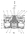
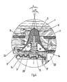
Fig. 1 bis 5 sind zwei Ausführungsbeispiele gezeigt. Das Hydrolager 30,Fig. 3 , besteht aus dem Traglager 31 und dem Auflager 32. Ein konusförmiger Federkörper 33 aus elastomerem Material verbindet Traglager 31 und Auflager 32. Der Arbeitsraum 1 wird vom Ausgleichsraum 2 durch die Trennwand 3 getrennt. Beide Räume 1 und 2 sind mit einer Flüssigkeit gefüllt. Der Ausgleichsraum 2 ist durch die Rollmembran 34 abgeschlossen. Arbeitsraum 1 und Ausgleichsraum 2 sind über den Dämpfungskanal 4 miteinander verbunden. In der Trennwand 3 befindet sich die verschließbare Durchbrechung 5 mit dem Verschlussstöpsel 6. Der Verschlussstöpsel 6 ist Teil eines Schalters 7, der in den Beispielen durch Unterdruck gesteuert wird. In beiden Ausführungen ist die Durchbrechung 5 und der Verschlussstöpsel 6 kegelstumpfartig ausgebildet. In die Trennwand ist des Weiteren eine Ringmembran 8 eingefügt, die zur Isolierung hochfrequenter Schwingungen mit kleiner Amplitude dient. - In den
Fig. 1 und2 ist eine Ausbildung gezeigt, bei der der Stöpsel 6 Teil der Rollmembran 34 ist. Unterhalb der Rollmembran 34 befindet sich die Feder 9 mit der Ringstütze 10, welche den Stöpsel 6 in die Durchbrechung 5 drücken,Fig. 1 . Feder 9 und Ringstütze 10 sind Teil der Steuerdruckdose 14 des Schalters 7. Ab einem vorgegebenen Unterdruck in der Steuerdruckdose 14 wird die Federkraft überwunden und der Stöpsel 6 nach unten gezogen und die Durchbrechung 5 geöffnet,Fig. 2 . - In den
Fig. 3 bis 5 ist die bevorzugte Ausführungsform gezeigt, bei der der Stöpsel 6 Teil des Schalters 7 ist, der innerhalb des Ausgleichsraumes 2 untergebracht ist. Bei geöffneter Durchbrechung 5 entsteht zwischen der Innenwand 12, der Durchbrechung 5 und der Außenwand 13 des Verschlussstöpsels 6 eine Flüssigkeitssäule, welche während des Leerlaufs des Motors eine Tilgerwirkung der in das Lager 30 eingeleiteten Schwingungen zur Folge hat. Die Querschnütsflächen der Flüssigkeitssäule sind über die gesamte Höhe der Durchbrechung 5 gleichbleibend. Insbesondere sind die Querschnittsflächen der Flüssigkeitssäule an den Durchlässen zum Arbeitsraum 2 in ihrer Flächengröße identisch. - Die Kegelwinkel α und β an der Innenwand 12 der Durchbrechung 5 und an der Außenwand 13 des Verschlussstöpsels 6 weichen voneinander ab. Dabei ist der Kegelwinkel α des Verschlussstöpsels 6 größer als der Kegelwinkel β der Durchbrechung 5. Dabei ist es günstig, wenn bei der Durchbrechung 5 und am Verschlussstöpsel 6 über deren gesamte Höhe die jeweiligen Kegelwinkel α und β einheitlich sind.
- Der in den
Fig. 3 bis 5 gezeigte Unterdruckschalter 7 besteht aus der Druckdose 14, der Schließfeder 15 und dem Schließstöpsel 6. Die Druckdose 14 hat den steifen Boden 17 und die darauf aufgesetzte konusartige Hülle 18 aus einem elastomeren Material. An der Hülle 18 befindet sich der Schüeßstöpsel 6. Der Boden 17 ist aus einem Kunststoff hergestellt. Hülle 18 und Schließstöpsel 6 sind ein einheitliches Teil. - Der Boden 17 und die Hülle 18 sind an ihren Rändern wasserdicht miteinander verbunden. Dieses erfolgt durch ein Verklemmen am Bodenrand über den Klemmaufsatz 22, Die Schließfeder 15 ist eine innerhalb der Druckdose angeordnete Schraubenfeder. Am Boden 17 ist die Aufnahme 20 für die Schließfeder 15 gebildet. Während das obere Ende der Schraubenfeder 15 mit dem Einsatz 21 versehen ist, der sich in eine Vertiefung im Schließstöpsel 6 einfügt.
- Der Innenraum der Druckdose 14 ist mit einem nicht näher gezeigten Druckgenerator verbunden. Hierfür ist an der Unterseite des Auflagers 3 der Anschluss 23 vorhanden, der über einen Kanal im Boden 17 mit dem Innenraum der Druckdose 14 verbunden ist,
- In der
Fig. 4 ist die Durchbrechung 5 durch den Stöpsel 6 verschlossen. Die Schließfeder 15 drückt den Stöpsel 6 gegen die Trennwand 3 im Bereich der Durchbrechung 5 und hält den Stöpsel 6 in dieser Lage. Die Drücke der Flüssigkeit im Ausgleichsraum 2 und der Druckluft im Innenraum der Druckdose 14 sind in etwa gleich, sodass der Druck durch die Schließfeder 15 auf den Stöpsel 6 sehr gering gehalten werden kann. Die Steuerung des Innendrucks im Innenraum der Druckdose 14 wird so vorgenommen, dass im Leerlauf ein Unterdruck aufgebaut wird, sodass der Gegendruck der Feder 15 überwunden wird. Durch den Unterdruck im Innenraum wird die Durchbrechung 5 geöffnet, sodass eine Schwingungstilgung im Leerlauf durch die in der Durchbrechung vorhandene Flüssigkeitssäule eintritt. Der angelegte Unterdruck kann so gesteuert werden, dass eine vollständige Öffnung der Durchbrechung 5 eintritt oder auch nur eine Teilweise Öffnung. - Bei dem Ausführungsbeispiel hat die Hülle 18 an ihrem Rand eine umlaufende Wulst, um eine gute Abdichtung der Druckdose 14 gegenüber dem Druck der Flüssigkeit im Ausgleichsraum 2 zu erreichen.
Claims (15)
- Umschaltbares Motorlager (30) aus einem Traglager (31) und einem Auflager (32), die durch einen elastomeren Federkörper (33) miteinander verbunden sind, und das einen Arbeitsraum (1) und einen Ausgleichsraum (2) hat, welche durch eine Trennwand (3) getrennt und mit einer Flüssigkeit gefüllt sind und die über einen Dämpfungskanal (4) hydraulisch miteinander verbunden sind, wobei die Trennwand (3) eine über einen Schalter (7) verschließbare Durchbrechung (5) aufweist, dadurch gekennzeichnet, dass die Durchbrechung (5) und der Verschlussstöpsel (6) kegelstumpfartig ausgebildet sind und der Verschlussstöpsel (6) in die Durchbrechung (5) hineinragt.
- Umschaltbares Motorlager nach Anspruch 1, dadurch gekennzeichnet, dass bei geöffneter Durchbrechung (5) die zwischen der Innenwand (12) der Durchbrechung (5) und der Außenwand (13) des Verschlussstöpsels (6) vorhandene Flüssigkeitssäule in ihren Querschnittsflächen gleichbleibend ist.
- Umschaltbares Motorlager nach Anspruch 1, dadurch gekennzeichnet, dass bei geöffneter Durchbrechung (5) die Querschnittsflächen der Flüssigkeitssäule an den Durchlässen zum Arbeitsraum und zum Ausgleichsraum (1) in ihrer Flächengröße identisch sind.
- Umschaltbares Motorlager nach einem der Ansprüche 1 bis 3, dadurch gekennzeichnet, dass die Kegelwinkel (α und β) an der Innenwand (12) der Durchbrechung (5) und an der Außenwand (13) des Verschlussstöpsels (6) voneinander abweichen.
- Umschaltbares Motorlager nach Anspruch 4, dadurch gekennzeichnet, dass der Kegelwinkel (α) des Verschlussstöpsels (6) größer als der Kegeiwinkel (β) der Durchbrechung (5) ist.
- Umschaltbares Motorlager nach Anspruch 4, dadurch gekennzeichnet, dass an der Durchbrechung (5) und am Verschlussstöpsel (6) über deren gesamte Höhe einheitliche Kegelwinkel (α und β) vorhanden sind.
- Umschaltbares Motorlager nach einem der Ansprüche 1 bis 6, dadurch gekennzeichnet, dass der Schalter (7) eine Druckdose hat, deren Innenraum an einen Druckgenerator angeschlossen ist.
- Umschaltbares Motarlager nach einem der Ansprüche 1 bis 7, dadurch gekennzeichnet, dass der durch Unterdruck gesteuerte Schalter (7) aus einer Druckdose (14), einer Schließfeder (15) und einem Schließstöpsel (6) besteht.
- Umschaltbares Motorlager nach einem der Ansprüche 1 bis 8, dadurch gekennzeichnet, dass die Druckdose (14) aus einem steifen Boden (17) und einer daran aufgesetzten konusartigen Hülle (18) aus einem elastomeren Material mit einem Verschlussstöpsel (6) an ihrer Oberseite besteht.
- Umschaltbares Motorlager nach Anspruch 9, dadurch gekennzeichnet, dass der Boden (17) aus einem Kunststoff hergestellt ist.
- Umschaltbares Motorlager nach einem der Ansprüche 9 oder 10, dadurch gekennzeichnet, dass die Hülle (18) und der Verschlussstöpsel (6) ein einheitliches Teil sind.
- Umschaltbares Motorlager nach einem der Ansprüche 9 bis 11, dadurch gekennzeichnet, dass der Boden (17) und die Hülle (18) wasserdicht miteinander verbunden sind.
- Umschaltbares Motorlager nach einem der Ansprüche 9 bis 12, dadurch gekennzeichnet, dass die Schließfeder (15) eine innerhalb der Druckdose (14) angeordnete Schraubenfeder ist.
- Umschaltbares Motorlager nach einem der Ansprüche 9 bis 13, dadurch gekennzeichnet, dass am Boden (17) und am Verschlussstöpsel (6) Aufnahmen (20) für die Enden der Schraubenfeder (15) vorhanden sind.
- Umschaltbares Motorlager nach Anspruch 14, dadurch gekennzeichnet, dass das obere Ende der Schraubenfeder (15) mit einem Einsatz (21) aus Kunststoff versehen ist.
Priority Applications (4)
| Application Number | Priority Date | Filing Date | Title |
|---|---|---|---|
| ES12008337.3T ES2643472T3 (es) | 2012-12-14 | 2012-12-14 | Soporte de motor conmutable |
| EP12008337.3A EP2743540B1 (de) | 2012-12-14 | 2012-12-14 | Umschaltbares Motorlager |
| PL12008337T PL2743540T3 (pl) | 2012-12-14 | 2012-12-14 | Przełączalne łożysko silnika |
| CN201310466906.8A CN103867632B (zh) | 2012-12-14 | 2013-10-09 | 可切换的发动机悬置装置 |
Applications Claiming Priority (1)
| Application Number | Priority Date | Filing Date | Title |
|---|---|---|---|
| EP12008337.3A EP2743540B1 (de) | 2012-12-14 | 2012-12-14 | Umschaltbares Motorlager |
Publications (2)
| Publication Number | Publication Date |
|---|---|
| EP2743540A1 true EP2743540A1 (de) | 2014-06-18 |
| EP2743540B1 EP2743540B1 (de) | 2017-08-09 |
Family
ID=47552729
Family Applications (1)
| Application Number | Title | Priority Date | Filing Date |
|---|---|---|---|
| EP12008337.3A Not-in-force EP2743540B1 (de) | 2012-12-14 | 2012-12-14 | Umschaltbares Motorlager |
Country Status (4)
| Country | Link |
|---|---|
| EP (1) | EP2743540B1 (de) |
| CN (1) | CN103867632B (de) |
| ES (1) | ES2643472T3 (de) |
| PL (1) | PL2743540T3 (de) |
Cited By (1)
| Publication number | Priority date | Publication date | Assignee | Title |
|---|---|---|---|---|
| WO2018141531A1 (de) * | 2017-02-01 | 2018-08-09 | Vibracoustic Gmbh | Hydrolager |
Families Citing this family (3)
| Publication number | Priority date | Publication date | Assignee | Title |
|---|---|---|---|---|
| FR3057216B1 (fr) * | 2016-10-06 | 2018-10-26 | Peugeot Citroen Automobiles Sa | Cale composite pour groupe motopropulseur |
| FR3057217B1 (fr) * | 2016-10-06 | 2018-11-09 | Peugeot Citroen Automobiles Sa | Cale allegee pour groupe motopropulseur apte a limiter des efforts transversaux |
| DE102018216477B4 (de) | 2018-09-26 | 2023-03-16 | Robert Bosch Gmbh | Lenkvorrichtung mit einer Steckverbindereinheit zur elektrischen Kontaktierung einer Lenksensoreinheit |
Citations (7)
| Publication number | Priority date | Publication date | Assignee | Title |
|---|---|---|---|---|
| JPS60116937A (ja) * | 1983-11-28 | 1985-06-24 | Toyota Motor Corp | 車輌用内燃機関の防振支持方法 |
| US4877225A (en) * | 1987-06-29 | 1989-10-31 | Bridgestone Corp. | Vibration isolator |
| DE4141332C2 (de) | 1991-12-14 | 1995-05-24 | Freudenberg Carl Fa | Umschaltbares Lager |
| DE19807868A1 (de) | 1998-02-25 | 1999-09-09 | Freudenberg Carl Fa | Hydraulisch dämpfendes Lager |
| DE10348964A1 (de) | 2003-10-22 | 2005-06-09 | Carl Freudenberg Kg | Hydrolager |
| EP1544501A1 (de) * | 2003-12-18 | 2005-06-22 | Vibracoustic GmbH & Co. KG | Hydraulisch dämpfendes Stützlager |
| EP2093456A2 (de) * | 2008-02-22 | 2009-08-26 | Carl Freudenberg KG | Hydrolager |
Family Cites Families (2)
| Publication number | Priority date | Publication date | Assignee | Title |
|---|---|---|---|---|
| DE19861063C2 (de) * | 1998-02-25 | 2002-02-14 | Freudenberg Carl Kg | Hydraulisch dämpfendes Lager |
| CN201317260Y (zh) * | 2008-11-28 | 2009-09-30 | 安徽江淮汽车股份有限公司 | 中型卡车发动机悬置机构 |
-
2012
- 2012-12-14 ES ES12008337.3T patent/ES2643472T3/es active Active
- 2012-12-14 EP EP12008337.3A patent/EP2743540B1/de not_active Not-in-force
- 2012-12-14 PL PL12008337T patent/PL2743540T3/pl unknown
-
2013
- 2013-10-09 CN CN201310466906.8A patent/CN103867632B/zh not_active Expired - Fee Related
Patent Citations (7)
| Publication number | Priority date | Publication date | Assignee | Title |
|---|---|---|---|---|
| JPS60116937A (ja) * | 1983-11-28 | 1985-06-24 | Toyota Motor Corp | 車輌用内燃機関の防振支持方法 |
| US4877225A (en) * | 1987-06-29 | 1989-10-31 | Bridgestone Corp. | Vibration isolator |
| DE4141332C2 (de) | 1991-12-14 | 1995-05-24 | Freudenberg Carl Fa | Umschaltbares Lager |
| DE19807868A1 (de) | 1998-02-25 | 1999-09-09 | Freudenberg Carl Fa | Hydraulisch dämpfendes Lager |
| DE10348964A1 (de) | 2003-10-22 | 2005-06-09 | Carl Freudenberg Kg | Hydrolager |
| EP1544501A1 (de) * | 2003-12-18 | 2005-06-22 | Vibracoustic GmbH & Co. KG | Hydraulisch dämpfendes Stützlager |
| EP2093456A2 (de) * | 2008-02-22 | 2009-08-26 | Carl Freudenberg KG | Hydrolager |
Cited By (2)
| Publication number | Priority date | Publication date | Assignee | Title |
|---|---|---|---|---|
| WO2018141531A1 (de) * | 2017-02-01 | 2018-08-09 | Vibracoustic Gmbh | Hydrolager |
| US10941832B2 (en) | 2017-02-01 | 2021-03-09 | Vibracoustic Gmbh | Hydromount |
Also Published As
| Publication number | Publication date |
|---|---|
| CN103867632B (zh) | 2016-08-17 |
| CN103867632A (zh) | 2014-06-18 |
| PL2743540T3 (pl) | 2018-01-31 |
| EP2743540B1 (de) | 2017-08-09 |
| ES2643472T3 (es) | 2017-11-23 |
Similar Documents
| Publication | Publication Date | Title |
|---|---|---|
| DE3133839C2 (de) | ||
| DE102012014583B4 (de) | Ventilstruktur eines Schwingungsdämpfers | |
| DE102007017589B3 (de) | Dämpfungsvorrichtung mit feldsteuerbarer Flüssigkeit | |
| EP2287492B1 (de) | Hydropneumatischer Kolbenspeicher | |
| DE102018122135B4 (de) | Antriebsanordnung für eine Klappe eines Kraftfahrzeugs | |
| DE102013111502A1 (de) | Schwingungsdämpfer mit amplitudenabhängiger Dämpfung | |
| EP2743540B1 (de) | Umschaltbares Motorlager | |
| DE2312445B2 (de) | Hydraulischer Stoßdämpfer | |
| EP4153884B1 (de) | Gasdruckfeder und herstellungsverfahren der gasdruckfeder | |
| WO2011026786A1 (de) | Hydrolager | |
| DE112012002322T5 (de) | Flüssigkeitsgedichtete vibrationsisolierende Vorrichtung | |
| WO2014127955A1 (de) | Hydraulikeinheit | |
| DE102017008752A1 (de) | Hydraulische Dämpfvorrichtung | |
| DE3828132C2 (de) | Elastische Aufhängung mit einer Flüssigkeitsfüllung | |
| EP0831245A2 (de) | Industrie-Stossdämpfer | |
| DE2109398A1 (de) | Stoßdämpferventil mit kontinuierlichem Übergang | |
| DE102019208414A1 (de) | Bremssystemdämpfvorrichtung | |
| DE19856697C2 (de) | Schwingungsdämpfer zur Dämpfung von Flüssigkeits-Schwingungen in einem hydraulischen System | |
| WO1999021774A1 (de) | Schraubkappe aus kunststoff zum verschluss einer flasche oder dergleichen | |
| EP2743539B1 (de) | Umschaltbares Motorlager | |
| DE3030616A1 (de) | Einstellbarer druckstossdaempfer | |
| DE102019210649A1 (de) | Bremssystemdämpfvorrichtung mit einem Durchlass | |
| DE19807868A1 (de) | Hydraulisch dämpfendes Lager | |
| DE2522443A1 (de) | Wasserschadenschutzventil | |
| DE60219485T2 (de) | Einsatz für dynamische flusssteuerung |
Legal Events
| Date | Code | Title | Description |
|---|---|---|---|
| PUAI | Public reference made under article 153(3) epc to a published international application that has entered the european phase |
Free format text: ORIGINAL CODE: 0009012 |
|
| 17P | Request for examination filed |
Effective date: 20121214 |
|
| AK | Designated contracting states |
Kind code of ref document: A1 Designated state(s): AL AT BE BG CH CY CZ DE DK EE ES FI FR GB GR HR HU IE IS IT LI LT LU LV MC MK MT NL NO PL PT RO RS SE SI SK SM TR |
|
| AX | Request for extension of the european patent |
Extension state: BA ME |
|
| R17P | Request for examination filed (corrected) |
Effective date: 20141217 |
|
| RBV | Designated contracting states (corrected) |
Designated state(s): AL AT BE BG CH CY CZ DE DK EE ES FI FR GB GR HR HU IE IS IT LI LT LU LV MC MK MT NL NO PL PT RO RS SE SI SK SM TR |
|
| RAP1 | Party data changed (applicant data changed or rights of an application transferred) |
Owner name: VIBRACOUSTIC GMBH |
|
| GRAP | Despatch of communication of intention to grant a patent |
Free format text: ORIGINAL CODE: EPIDOSNIGR1 |
|
| INTG | Intention to grant announced |
Effective date: 20170425 |
|
| GRAS | Grant fee paid |
Free format text: ORIGINAL CODE: EPIDOSNIGR3 |
|
| GRAA | (expected) grant |
Free format text: ORIGINAL CODE: 0009210 |
|
| AK | Designated contracting states |
Kind code of ref document: B1 Designated state(s): AL AT BE BG CH CY CZ DE DK EE ES FI FR GB GR HR HU IE IS IT LI LT LU LV MC MK MT NL NO PL PT RO RS SE SI SK SM TR |
|
| REG | Reference to a national code |
Ref country code: GB Ref legal event code: FG4D Free format text: NOT ENGLISH |
|
| REG | Reference to a national code |
Ref country code: CH Ref legal event code: EP Ref country code: AT Ref legal event code: REF Ref document number: 917205 Country of ref document: AT Kind code of ref document: T Effective date: 20170815 |
|
| REG | Reference to a national code |
Ref country code: IE Ref legal event code: FG4D Free format text: LANGUAGE OF EP DOCUMENT: GERMAN |
|
| REG | Reference to a national code |
Ref country code: DE Ref legal event code: R096 Ref document number: 502012010947 Country of ref document: DE |
|
| REG | Reference to a national code |
Ref country code: RO Ref legal event code: EPE |
|
| REG | Reference to a national code |
Ref country code: ES Ref legal event code: FG2A Ref document number: 2643472 Country of ref document: ES Kind code of ref document: T3 Effective date: 20171123 |
|
| REG | Reference to a national code |
Ref country code: NL Ref legal event code: MP Effective date: 20170809 |
|
| REG | Reference to a national code |
Ref country code: FR Ref legal event code: PLFP Year of fee payment: 6 |
|
| REG | Reference to a national code |
Ref country code: LT Ref legal event code: MG4D |
|
| PG25 | Lapsed in a contracting state [announced via postgrant information from national office to epo] |
Ref country code: NL Free format text: LAPSE BECAUSE OF FAILURE TO SUBMIT A TRANSLATION OF THE DESCRIPTION OR TO PAY THE FEE WITHIN THE PRESCRIBED TIME-LIMIT Effective date: 20170809 Ref country code: LT Free format text: LAPSE BECAUSE OF FAILURE TO SUBMIT A TRANSLATION OF THE DESCRIPTION OR TO PAY THE FEE WITHIN THE PRESCRIBED TIME-LIMIT Effective date: 20170809 Ref country code: SE Free format text: LAPSE BECAUSE OF FAILURE TO SUBMIT A TRANSLATION OF THE DESCRIPTION OR TO PAY THE FEE WITHIN THE PRESCRIBED TIME-LIMIT Effective date: 20170809 Ref country code: NO Free format text: LAPSE BECAUSE OF FAILURE TO SUBMIT A TRANSLATION OF THE DESCRIPTION OR TO PAY THE FEE WITHIN THE PRESCRIBED TIME-LIMIT Effective date: 20171109 Ref country code: HR Free format text: LAPSE BECAUSE OF FAILURE TO SUBMIT A TRANSLATION OF THE DESCRIPTION OR TO PAY THE FEE WITHIN THE PRESCRIBED TIME-LIMIT Effective date: 20170809 Ref country code: FI Free format text: LAPSE BECAUSE OF FAILURE TO SUBMIT A TRANSLATION OF THE DESCRIPTION OR TO PAY THE FEE WITHIN THE PRESCRIBED TIME-LIMIT Effective date: 20170809 |
|
| PGFP | Annual fee paid to national office [announced via postgrant information from national office to epo] |
Ref country code: TR Payment date: 20171213 Year of fee payment: 6 |
|
| PG25 | Lapsed in a contracting state [announced via postgrant information from national office to epo] |
Ref country code: LV Free format text: LAPSE BECAUSE OF FAILURE TO SUBMIT A TRANSLATION OF THE DESCRIPTION OR TO PAY THE FEE WITHIN THE PRESCRIBED TIME-LIMIT Effective date: 20170809 Ref country code: IS Free format text: LAPSE BECAUSE OF FAILURE TO SUBMIT A TRANSLATION OF THE DESCRIPTION OR TO PAY THE FEE WITHIN THE PRESCRIBED TIME-LIMIT Effective date: 20171209 Ref country code: BG Free format text: LAPSE BECAUSE OF FAILURE TO SUBMIT A TRANSLATION OF THE DESCRIPTION OR TO PAY THE FEE WITHIN THE PRESCRIBED TIME-LIMIT Effective date: 20171109 Ref country code: RS Free format text: LAPSE BECAUSE OF FAILURE TO SUBMIT A TRANSLATION OF THE DESCRIPTION OR TO PAY THE FEE WITHIN THE PRESCRIBED TIME-LIMIT Effective date: 20170809 Ref country code: GR Free format text: LAPSE BECAUSE OF FAILURE TO SUBMIT A TRANSLATION OF THE DESCRIPTION OR TO PAY THE FEE WITHIN THE PRESCRIBED TIME-LIMIT Effective date: 20171110 |
|
| PG25 | Lapsed in a contracting state [announced via postgrant information from national office to epo] |
Ref country code: DK Free format text: LAPSE BECAUSE OF FAILURE TO SUBMIT A TRANSLATION OF THE DESCRIPTION OR TO PAY THE FEE WITHIN THE PRESCRIBED TIME-LIMIT Effective date: 20170809 |
|
| REG | Reference to a national code |
Ref country code: DE Ref legal event code: R097 Ref document number: 502012010947 Country of ref document: DE |
|
| PG25 | Lapsed in a contracting state [announced via postgrant information from national office to epo] |
Ref country code: SM Free format text: LAPSE BECAUSE OF FAILURE TO SUBMIT A TRANSLATION OF THE DESCRIPTION OR TO PAY THE FEE WITHIN THE PRESCRIBED TIME-LIMIT Effective date: 20170809 Ref country code: IT Free format text: LAPSE BECAUSE OF FAILURE TO SUBMIT A TRANSLATION OF THE DESCRIPTION OR TO PAY THE FEE WITHIN THE PRESCRIBED TIME-LIMIT Effective date: 20170809 Ref country code: EE Free format text: LAPSE BECAUSE OF FAILURE TO SUBMIT A TRANSLATION OF THE DESCRIPTION OR TO PAY THE FEE WITHIN THE PRESCRIBED TIME-LIMIT Effective date: 20170809 |
|
| PLBE | No opposition filed within time limit |
Free format text: ORIGINAL CODE: 0009261 |
|
| STAA | Information on the status of an ep patent application or granted ep patent |
Free format text: STATUS: NO OPPOSITION FILED WITHIN TIME LIMIT |
|
| 26N | No opposition filed |
Effective date: 20180511 |
|
| REG | Reference to a national code |
Ref country code: CH Ref legal event code: PL |
|
| PG25 | Lapsed in a contracting state [announced via postgrant information from national office to epo] |
Ref country code: SI Free format text: LAPSE BECAUSE OF FAILURE TO SUBMIT A TRANSLATION OF THE DESCRIPTION OR TO PAY THE FEE WITHIN THE PRESCRIBED TIME-LIMIT Effective date: 20170809 |
|
| PG25 | Lapsed in a contracting state [announced via postgrant information from national office to epo] |
Ref country code: MT Free format text: LAPSE BECAUSE OF FAILURE TO SUBMIT A TRANSLATION OF THE DESCRIPTION OR TO PAY THE FEE WITHIN THE PRESCRIBED TIME-LIMIT Effective date: 20170809 Ref country code: LU Free format text: LAPSE BECAUSE OF NON-PAYMENT OF DUE FEES Effective date: 20171214 |
|
| REG | Reference to a national code |
Ref country code: BE Ref legal event code: MM Effective date: 20171231 |
|
| PG25 | Lapsed in a contracting state [announced via postgrant information from national office to epo] |
Ref country code: LI Free format text: LAPSE BECAUSE OF NON-PAYMENT OF DUE FEES Effective date: 20171231 Ref country code: CH Free format text: LAPSE BECAUSE OF NON-PAYMENT OF DUE FEES Effective date: 20171231 Ref country code: BE Free format text: LAPSE BECAUSE OF NON-PAYMENT OF DUE FEES Effective date: 20171231 |
|
| PGFP | Annual fee paid to national office [announced via postgrant information from national office to epo] |
Ref country code: SE Payment date: 20181219 Year of fee payment: 7 Ref country code: RO Payment date: 20181210 Year of fee payment: 7 |
|
| REG | Reference to a national code |
Ref country code: AT Ref legal event code: MM01 Ref document number: 917205 Country of ref document: AT Kind code of ref document: T Effective date: 20171214 |
|
| PG25 | Lapsed in a contracting state [announced via postgrant information from national office to epo] |
Ref country code: AT Free format text: LAPSE BECAUSE OF NON-PAYMENT OF DUE FEES Effective date: 20171214 |
|
| PG25 | Lapsed in a contracting state [announced via postgrant information from national office to epo] |
Ref country code: MC Free format text: LAPSE BECAUSE OF FAILURE TO SUBMIT A TRANSLATION OF THE DESCRIPTION OR TO PAY THE FEE WITHIN THE PRESCRIBED TIME-LIMIT Effective date: 20170809 Ref country code: HU Free format text: LAPSE BECAUSE OF FAILURE TO SUBMIT A TRANSLATION OF THE DESCRIPTION OR TO PAY THE FEE WITHIN THE PRESCRIBED TIME-LIMIT; INVALID AB INITIO Effective date: 20121214 |
|
| PG25 | Lapsed in a contracting state [announced via postgrant information from national office to epo] |
Ref country code: CY Free format text: LAPSE BECAUSE OF NON-PAYMENT OF DUE FEES Effective date: 20170809 |
|
| PG25 | Lapsed in a contracting state [announced via postgrant information from national office to epo] |
Ref country code: MK Free format text: LAPSE BECAUSE OF FAILURE TO SUBMIT A TRANSLATION OF THE DESCRIPTION OR TO PAY THE FEE WITHIN THE PRESCRIBED TIME-LIMIT Effective date: 20170809 |
|
| PGFP | Annual fee paid to national office [announced via postgrant information from national office to epo] |
Ref country code: IE Payment date: 20191217 Year of fee payment: 8 Ref country code: CZ Payment date: 20191203 Year of fee payment: 8 |
|
| REG | Reference to a national code |
Ref country code: DE Ref legal event code: R082 Ref document number: 502012010947 Country of ref document: DE Representative=s name: PATENTANWAELTE OLBRICHT, BUCHHOLD, KEULERTZ PA, DE |
|
| PGFP | Annual fee paid to national office [announced via postgrant information from national office to epo] |
Ref country code: ES Payment date: 20200122 Year of fee payment: 8 |
|
| PG25 | Lapsed in a contracting state [announced via postgrant information from national office to epo] |
Ref country code: PT Free format text: LAPSE BECAUSE OF FAILURE TO SUBMIT A TRANSLATION OF THE DESCRIPTION OR TO PAY THE FEE WITHIN THE PRESCRIBED TIME-LIMIT Effective date: 20170809 |
|
| PG25 | Lapsed in a contracting state [announced via postgrant information from national office to epo] |
Ref country code: RO Free format text: LAPSE BECAUSE OF NON-PAYMENT OF DUE FEES Effective date: 20191214 Ref country code: AL Free format text: LAPSE BECAUSE OF FAILURE TO SUBMIT A TRANSLATION OF THE DESCRIPTION OR TO PAY THE FEE WITHIN THE PRESCRIBED TIME-LIMIT Effective date: 20170809 |
|
| REG | Reference to a national code |
Ref country code: SK Ref legal event code: MM4A Ref document number: E 25585 Country of ref document: SK Effective date: 20191214 |
|
| PG25 | Lapsed in a contracting state [announced via postgrant information from national office to epo] |
Ref country code: SK Free format text: LAPSE BECAUSE OF NON-PAYMENT OF DUE FEES Effective date: 20191214 |
|
| PG25 | Lapsed in a contracting state [announced via postgrant information from national office to epo] |
Ref country code: CZ Free format text: LAPSE BECAUSE OF NON-PAYMENT OF DUE FEES Effective date: 20201214 |
|
| REG | Reference to a national code |
Ref country code: DE Ref legal event code: R081 Ref document number: 502012010947 Country of ref document: DE Owner name: VIBRACOUSTIC SE, DE Free format text: FORMER OWNER: VIBRACOUSTIC GMBH, 64293 DARMSTADT, DE |
|
| PG25 | Lapsed in a contracting state [announced via postgrant information from national office to epo] |
Ref country code: IE Free format text: LAPSE BECAUSE OF NON-PAYMENT OF DUE FEES Effective date: 20201214 |
|
| PGFP | Annual fee paid to national office [announced via postgrant information from national office to epo] |
Ref country code: GB Payment date: 20211222 Year of fee payment: 10 Ref country code: FR Payment date: 20211224 Year of fee payment: 10 Ref country code: DE Payment date: 20211231 Year of fee payment: 10 |
|
| REG | Reference to a national code |
Ref country code: ES Ref legal event code: FD2A Effective date: 20220411 |
|
| PG25 | Lapsed in a contracting state [announced via postgrant information from national office to epo] |
Ref country code: PL Free format text: LAPSE BECAUSE OF NON-PAYMENT OF DUE FEES Effective date: 20191214 |
|
| PG25 | Lapsed in a contracting state [announced via postgrant information from national office to epo] |
Ref country code: TR Free format text: LAPSE BECAUSE OF NON-PAYMENT OF DUE FEES Effective date: 20191214 |
|
| PG25 | Lapsed in a contracting state [announced via postgrant information from national office to epo] |
Ref country code: ES Free format text: LAPSE BECAUSE OF NON-PAYMENT OF DUE FEES Effective date: 20201215 |
|
| REG | Reference to a national code |
Ref country code: DE Ref legal event code: R119 Ref document number: 502012010947 Country of ref document: DE |
|
| GBPC | Gb: european patent ceased through non-payment of renewal fee |
Effective date: 20221214 |
|
| PG25 | Lapsed in a contracting state [announced via postgrant information from national office to epo] |
Ref country code: GB Free format text: LAPSE BECAUSE OF NON-PAYMENT OF DUE FEES Effective date: 20221214 Ref country code: DE Free format text: LAPSE BECAUSE OF NON-PAYMENT OF DUE FEES Effective date: 20230701 |
|
| PG25 | Lapsed in a contracting state [announced via postgrant information from national office to epo] |
Ref country code: FR Free format text: LAPSE BECAUSE OF NON-PAYMENT OF DUE FEES Effective date: 20221231 |