EP2739504B1 - Kraftfahrzeug und verfahren zur herstellung eines solchen kraftfahrzeugs - Google Patents
Kraftfahrzeug und verfahren zur herstellung eines solchen kraftfahrzeugs Download PDFInfo
- Publication number
- EP2739504B1 EP2739504B1 EP12745816.4A EP12745816A EP2739504B1 EP 2739504 B1 EP2739504 B1 EP 2739504B1 EP 12745816 A EP12745816 A EP 12745816A EP 2739504 B1 EP2739504 B1 EP 2739504B1
- Authority
- EP
- European Patent Office
- Prior art keywords
- rail
- seat
- blank
- rails
- motor vehicle
- Prior art date
- Legal status (The legal status is an assumption and is not a legal conclusion. Google has not performed a legal analysis and makes no representation as to the accuracy of the status listed.)
- Active
Links
Images




Classifications
-
- B—PERFORMING OPERATIONS; TRANSPORTING
- B60—VEHICLES IN GENERAL
- B60N—SEATS SPECIALLY ADAPTED FOR VEHICLES; VEHICLE PASSENGER ACCOMMODATION NOT OTHERWISE PROVIDED FOR
- B60N2/00—Seats specially adapted for vehicles; Arrangement or mounting of seats in vehicles
- B60N2/02—Seats specially adapted for vehicles; Arrangement or mounting of seats in vehicles the seat or part thereof being movable, e.g. adjustable
- B60N2/04—Seats specially adapted for vehicles; Arrangement or mounting of seats in vehicles the seat or part thereof being movable, e.g. adjustable the whole seat being movable
- B60N2/06—Seats specially adapted for vehicles; Arrangement or mounting of seats in vehicles the seat or part thereof being movable, e.g. adjustable the whole seat being movable slidable
-
- B—PERFORMING OPERATIONS; TRANSPORTING
- B21—MECHANICAL METAL-WORKING WITHOUT ESSENTIALLY REMOVING MATERIAL; PUNCHING METAL
- B21D—WORKING OR PROCESSING OF SHEET METAL OR METAL TUBES, RODS OR PROFILES WITHOUT ESSENTIALLY REMOVING MATERIAL; PUNCHING METAL
- B21D19/00—Flanging or other edge treatment, e.g. of tubes
- B21D19/08—Flanging or other edge treatment, e.g. of tubes by single or successive action of pressing tools, e.g. vice jaws
-
- B—PERFORMING OPERATIONS; TRANSPORTING
- B60—VEHICLES IN GENERAL
- B60N—SEATS SPECIALLY ADAPTED FOR VEHICLES; VEHICLE PASSENGER ACCOMMODATION NOT OTHERWISE PROVIDED FOR
- B60N2/00—Seats specially adapted for vehicles; Arrangement or mounting of seats in vehicles
- B60N2/02—Seats specially adapted for vehicles; Arrangement or mounting of seats in vehicles the seat or part thereof being movable, e.g. adjustable
- B60N2/04—Seats specially adapted for vehicles; Arrangement or mounting of seats in vehicles the seat or part thereof being movable, e.g. adjustable the whole seat being movable
- B60N2/06—Seats specially adapted for vehicles; Arrangement or mounting of seats in vehicles the seat or part thereof being movable, e.g. adjustable the whole seat being movable slidable
- B60N2/07—Slide construction
- B60N2/075—Slide construction roller-less
-
- B—PERFORMING OPERATIONS; TRANSPORTING
- B21—MECHANICAL METAL-WORKING WITHOUT ESSENTIALLY REMOVING MATERIAL; PUNCHING METAL
- B21D—WORKING OR PROCESSING OF SHEET METAL OR METAL TUBES, RODS OR PROFILES WITHOUT ESSENTIALLY REMOVING MATERIAL; PUNCHING METAL
- B21D22/00—Shaping without cutting, by stamping, spinning, or deep-drawing
- B21D22/02—Stamping using rigid devices or tools
-
- B—PERFORMING OPERATIONS; TRANSPORTING
- B21—MECHANICAL METAL-WORKING WITHOUT ESSENTIALLY REMOVING MATERIAL; PUNCHING METAL
- B21D—WORKING OR PROCESSING OF SHEET METAL OR METAL TUBES, RODS OR PROFILES WITHOUT ESSENTIALLY REMOVING MATERIAL; PUNCHING METAL
- B21D5/00—Bending sheet metal along straight lines, e.g. to form simple curves
- B21D5/01—Bending sheet metal along straight lines, e.g. to form simple curves between rams and anvils or abutments
-
- B—PERFORMING OPERATIONS; TRANSPORTING
- B21—MECHANICAL METAL-WORKING WITHOUT ESSENTIALLY REMOVING MATERIAL; PUNCHING METAL
- B21D—WORKING OR PROCESSING OF SHEET METAL OR METAL TUBES, RODS OR PROFILES WITHOUT ESSENTIALLY REMOVING MATERIAL; PUNCHING METAL
- B21D53/00—Making other particular articles
- B21D53/88—Making other particular articles other parts for vehicles, e.g. cowlings, mudguards
-
- B—PERFORMING OPERATIONS; TRANSPORTING
- B60—VEHICLES IN GENERAL
- B60N—SEATS SPECIALLY ADAPTED FOR VEHICLES; VEHICLE PASSENGER ACCOMMODATION NOT OTHERWISE PROVIDED FOR
- B60N2/00—Seats specially adapted for vehicles; Arrangement or mounting of seats in vehicles
- B60N2/02—Seats specially adapted for vehicles; Arrangement or mounting of seats in vehicles the seat or part thereof being movable, e.g. adjustable
- B60N2/0224—Non-manual adjustments, e.g. with electrical operation
- B60N2/02246—Electric motors therefor
-
- B—PERFORMING OPERATIONS; TRANSPORTING
- B60—VEHICLES IN GENERAL
- B60N—SEATS SPECIALLY ADAPTED FOR VEHICLES; VEHICLE PASSENGER ACCOMMODATION NOT OTHERWISE PROVIDED FOR
- B60N2/00—Seats specially adapted for vehicles; Arrangement or mounting of seats in vehicles
- B60N2/02—Seats specially adapted for vehicles; Arrangement or mounting of seats in vehicles the seat or part thereof being movable, e.g. adjustable
- B60N2/04—Seats specially adapted for vehicles; Arrangement or mounting of seats in vehicles the seat or part thereof being movable, e.g. adjustable the whole seat being movable
- B60N2/06—Seats specially adapted for vehicles; Arrangement or mounting of seats in vehicles the seat or part thereof being movable, e.g. adjustable the whole seat being movable slidable
- B60N2/067—Seats specially adapted for vehicles; Arrangement or mounting of seats in vehicles the seat or part thereof being movable, e.g. adjustable the whole seat being movable slidable by linear actuators, e.g. linear screw mechanisms
-
- B—PERFORMING OPERATIONS; TRANSPORTING
- B60—VEHICLES IN GENERAL
- B60N—SEATS SPECIALLY ADAPTED FOR VEHICLES; VEHICLE PASSENGER ACCOMMODATION NOT OTHERWISE PROVIDED FOR
- B60N2/00—Seats specially adapted for vehicles; Arrangement or mounting of seats in vehicles
- B60N2/02—Seats specially adapted for vehicles; Arrangement or mounting of seats in vehicles the seat or part thereof being movable, e.g. adjustable
- B60N2/04—Seats specially adapted for vehicles; Arrangement or mounting of seats in vehicles the seat or part thereof being movable, e.g. adjustable the whole seat being movable
- B60N2/06—Seats specially adapted for vehicles; Arrangement or mounting of seats in vehicles the seat or part thereof being movable, e.g. adjustable the whole seat being movable slidable
- B60N2/07—Slide construction
-
- B—PERFORMING OPERATIONS; TRANSPORTING
- B60—VEHICLES IN GENERAL
- B60N—SEATS SPECIALLY ADAPTED FOR VEHICLES; VEHICLE PASSENGER ACCOMMODATION NOT OTHERWISE PROVIDED FOR
- B60N2/00—Seats specially adapted for vehicles; Arrangement or mounting of seats in vehicles
- B60N2/02—Seats specially adapted for vehicles; Arrangement or mounting of seats in vehicles the seat or part thereof being movable, e.g. adjustable
- B60N2/04—Seats specially adapted for vehicles; Arrangement or mounting of seats in vehicles the seat or part thereof being movable, e.g. adjustable the whole seat being movable
- B60N2/06—Seats specially adapted for vehicles; Arrangement or mounting of seats in vehicles the seat or part thereof being movable, e.g. adjustable the whole seat being movable slidable
- B60N2/07—Slide construction
- B60N2/0702—Slide construction characterised by its cross-section
- B60N2/0715—C or U-shaped
-
- B—PERFORMING OPERATIONS; TRANSPORTING
- B60—VEHICLES IN GENERAL
- B60N—SEATS SPECIALLY ADAPTED FOR VEHICLES; VEHICLE PASSENGER ACCOMMODATION NOT OTHERWISE PROVIDED FOR
- B60N2/00—Seats specially adapted for vehicles; Arrangement or mounting of seats in vehicles
- B60N2/02—Seats specially adapted for vehicles; Arrangement or mounting of seats in vehicles the seat or part thereof being movable, e.g. adjustable
- B60N2/04—Seats specially adapted for vehicles; Arrangement or mounting of seats in vehicles the seat or part thereof being movable, e.g. adjustable the whole seat being movable
- B60N2/06—Seats specially adapted for vehicles; Arrangement or mounting of seats in vehicles the seat or part thereof being movable, e.g. adjustable the whole seat being movable slidable
- B60N2/07—Slide construction
- B60N2/0735—Position and orientation of the slide as a whole
- B60N2/0745—Position and orientation of the slide as a whole the slide path being curved
-
- B—PERFORMING OPERATIONS; TRANSPORTING
- B60—VEHICLES IN GENERAL
- B60N—SEATS SPECIALLY ADAPTED FOR VEHICLES; VEHICLE PASSENGER ACCOMMODATION NOT OTHERWISE PROVIDED FOR
- B60N2/00—Seats specially adapted for vehicles; Arrangement or mounting of seats in vehicles
- B60N2/02—Seats specially adapted for vehicles; Arrangement or mounting of seats in vehicles the seat or part thereof being movable, e.g. adjustable
- B60N2/04—Seats specially adapted for vehicles; Arrangement or mounting of seats in vehicles the seat or part thereof being movable, e.g. adjustable the whole seat being movable
- B60N2/06—Seats specially adapted for vehicles; Arrangement or mounting of seats in vehicles the seat or part thereof being movable, e.g. adjustable the whole seat being movable slidable
- B60N2/07—Slide construction
- B60N2/0735—Position and orientation of the slide as a whole
- B60N2/0747—Position and orientation of the slide as a whole the opening of the cross section being oriented in a direction different from the vertical, e.g. transversal
-
- B—PERFORMING OPERATIONS; TRANSPORTING
- B60—VEHICLES IN GENERAL
- B60N—SEATS SPECIALLY ADAPTED FOR VEHICLES; VEHICLE PASSENGER ACCOMMODATION NOT OTHERWISE PROVIDED FOR
- B60N2/00—Seats specially adapted for vehicles; Arrangement or mounting of seats in vehicles
- B60N2/02—Seats specially adapted for vehicles; Arrangement or mounting of seats in vehicles the seat or part thereof being movable, e.g. adjustable
- B60N2/04—Seats specially adapted for vehicles; Arrangement or mounting of seats in vehicles the seat or part thereof being movable, e.g. adjustable the whole seat being movable
- B60N2/16—Seats specially adapted for vehicles; Arrangement or mounting of seats in vehicles the seat or part thereof being movable, e.g. adjustable the whole seat being movable height-adjustable
- B60N2/1695—Seats specially adapted for vehicles; Arrangement or mounting of seats in vehicles the seat or part thereof being movable, e.g. adjustable the whole seat being movable height-adjustable with simultaneous height and inclination adjustment
-
- B—PERFORMING OPERATIONS; TRANSPORTING
- B60—VEHICLES IN GENERAL
- B60N—SEATS SPECIALLY ADAPTED FOR VEHICLES; VEHICLE PASSENGER ACCOMMODATION NOT OTHERWISE PROVIDED FOR
- B60N2/00—Seats specially adapted for vehicles; Arrangement or mounting of seats in vehicles
- B60N2/02—Seats specially adapted for vehicles; Arrangement or mounting of seats in vehicles the seat or part thereof being movable, e.g. adjustable
- B60N2/04—Seats specially adapted for vehicles; Arrangement or mounting of seats in vehicles the seat or part thereof being movable, e.g. adjustable the whole seat being movable
- B60N2/16—Seats specially adapted for vehicles; Arrangement or mounting of seats in vehicles the seat or part thereof being movable, e.g. adjustable the whole seat being movable height-adjustable
- B60N2/18—Seats specially adapted for vehicles; Arrangement or mounting of seats in vehicles the seat or part thereof being movable, e.g. adjustable the whole seat being movable height-adjustable the front or the rear portion of the seat being adjustable, e.g. independently of each other
-
- B—PERFORMING OPERATIONS; TRANSPORTING
- B60—VEHICLES IN GENERAL
- B60N—SEATS SPECIALLY ADAPTED FOR VEHICLES; VEHICLE PASSENGER ACCOMMODATION NOT OTHERWISE PROVIDED FOR
- B60N2/00—Seats specially adapted for vehicles; Arrangement or mounting of seats in vehicles
- B60N2/02—Seats specially adapted for vehicles; Arrangement or mounting of seats in vehicles the seat or part thereof being movable, e.g. adjustable
- B60N2/04—Seats specially adapted for vehicles; Arrangement or mounting of seats in vehicles the seat or part thereof being movable, e.g. adjustable the whole seat being movable
- B60N2/16—Seats specially adapted for vehicles; Arrangement or mounting of seats in vehicles the seat or part thereof being movable, e.g. adjustable the whole seat being movable height-adjustable
- B60N2/18—Seats specially adapted for vehicles; Arrangement or mounting of seats in vehicles the seat or part thereof being movable, e.g. adjustable the whole seat being movable height-adjustable the front or the rear portion of the seat being adjustable, e.g. independently of each other
- B60N2/1807—Seats specially adapted for vehicles; Arrangement or mounting of seats in vehicles the seat or part thereof being movable, e.g. adjustable the whole seat being movable height-adjustable the front or the rear portion of the seat being adjustable, e.g. independently of each other characterised by the cinematic
- B60N2/1828—Slides only
- B60N2/1832—Slides only including a curved slide
-
- B—PERFORMING OPERATIONS; TRANSPORTING
- B60—VEHICLES IN GENERAL
- B60N—SEATS SPECIALLY ADAPTED FOR VEHICLES; VEHICLE PASSENGER ACCOMMODATION NOT OTHERWISE PROVIDED FOR
- B60N2/00—Seats specially adapted for vehicles; Arrangement or mounting of seats in vehicles
- B60N2/02—Seats specially adapted for vehicles; Arrangement or mounting of seats in vehicles the seat or part thereof being movable, e.g. adjustable
- B60N2/04—Seats specially adapted for vehicles; Arrangement or mounting of seats in vehicles the seat or part thereof being movable, e.g. adjustable the whole seat being movable
- B60N2/16—Seats specially adapted for vehicles; Arrangement or mounting of seats in vehicles the seat or part thereof being movable, e.g. adjustable the whole seat being movable height-adjustable
- B60N2/18—Seats specially adapted for vehicles; Arrangement or mounting of seats in vehicles the seat or part thereof being movable, e.g. adjustable the whole seat being movable height-adjustable the front or the rear portion of the seat being adjustable, e.g. independently of each other
- B60N2/185—Seats specially adapted for vehicles; Arrangement or mounting of seats in vehicles the seat or part thereof being movable, e.g. adjustable the whole seat being movable height-adjustable the front or the rear portion of the seat being adjustable, e.g. independently of each other characterised by the drive mechanism
- B60N2/1853—Linear actuator, e.g. screw mechanism
Definitions
- the invention relates to a motor vehicle according to the preamble of claim 1 and to a method for manufacturing.
- a motor vehicle seat is from the GB 2 071 486 A known.
- the JP H01 87042 U shows a similar motor vehicle seat.
- a rail guide is off DE 42 38 486 A1 , there for example FIG. 2 , previously known.
- Other rail guides are known from US 5,941,495 A and DE 10 2006 048 786 A1 , In addition, on DE 10 2006 047 525 A1 directed.
- the adjustment direction runs along the displacement path on a circular arc line. Due to the special choice of radii of curvature within the specified limits, it is achieved that a seat located far back in the rail guide is positioned somewhat more obliquely backwards and also lower than a seat set in the front region of the rail guide. This makes it possible to adapt to additional adjustment devices, for example a seat height adjustment and / or tilt adjustment of the backrest, to dispense. This means a considerable weight saving. In this way, a motor vehicle seat can be significantly lighter weight than in the prior art.
- the curve following a circular arc has a center of curvature, which is located in the installed state of the vehicle seat below this seat.
- the center of curvature is on the side of the rail guide that faces away from the seating area and the backrest.
- one of the two rails is preferably the clasping rail, the other the clasped rail.
- the two rails lie against each other with elastic bias.
- the two rails are by means of rolling or sliding against each other. These form the guiding means. Due to this elasticity manufacturing inaccuracies are compensated and the guide means held in position.
- the rails are both at least 25 cm long, one of the rails is at least 30 cm long.
- the rails are made of a steel sheet having a yield strength of at least 600 N / mm 2.
- the thickness range is 1.2 to 1.8 mm, preferably 1.5 + 10% and -30%. The thinner the sheet, the lower the weight of the rail.
- both rails are manufactured individually as stamped and bent parts. This is based on a blank made of sheet steel, in particular broadband. This blank is elongated, it is either banana or saber-shaped if the rail is to be mounted so that a base flange is in the xz plane, or substantially rectangular if the rail is to be mounted so that a base flange in the xy-plane lies. This blank is preferably bent in several individual bending steps in each case by two parallel bending lines. These are realized by bending bars. Bends are made along and near the longitudinal edges. Preferably, the profile of the finished rail is hinged or substantially symmetrical with respect to an axis perpendicular to the base flange.
- the method is as follows: In a first processing step, the blank is bent, wherein the bending line has a radius which coincides with or around the radius of curvature deviates up to 3%. The midpoint is near or on the midpoint line, which is parallel to the short edges of the blank. The blank then follows a cylinder jacket. In a second bending step are then left and right parallel to the respective longitudinal edge of the blank per side first leg bent. This is done around a bend line that lies on a circular arc. The bendline has a radius that can deviate from the radius of curvature by up to 3%. He usually does not agree with the radius of curvature.
- At least one further bending step at least one further leg is bent.
- the bends are made by bending strips are applied to the blank and bent around the bending bars.
- the bending bars have a curvature about the curvature means with a deviation in the radius of less than +/- 3% of the radius of curvature. Bending steps are carried out, as is also the case with straight rails. But now bending strips are used, which are not straight, but curved to the bending radius.
- the rail guide is associated with an actuator for the longitudinal adjustment.
- This actuator preferably has a rotary drive having an output shaft and a transmission having a spindle nut connected to the output shaft is rotatably connected and has a spindle, while the spindle has a spindle thread, with which the spindle nut is engaged, the spindle is curved in the same circular radius of curvature as the rails, the spindle nut is a straight nut.
- the motor vehicle seat is equipped with a motor adjusting device, which ensures the adjustment along the displacement path.
- the rotary drive can also be designed for manual adjustment. The rotary drive is then operated by hand. He has e.g. a crank, which is within reach of a passenger and over which the passenger initiates the rotational movement in the transmission.
- a prior art rail guide which is equipped without a rotary drive and with a manually operated locking device, no spring is required, which loads the seat forward within its rail guide. This spring must have a considerable spring force, it contributes to the total weight. Such a spring is saved.
- the bottom rail and the seat rail are each made of a suitable blank, this blank runs along the radii of curvature, which has the finished rail.
- the blanks are embossed in at least one respective embossing mold, embossing takes place in at least one embossing step. In this way, the finished rail is created.
- This method has the advantage that the desired accuracies are achieved. It can be produced in this way rails that are easily adjustable despite the curved course of the displacement, are precisely guided into each other and have good sliding properties.
- the bottom rail preferably has attachment regions, on which it is connectable to a bottom group of the motor vehicle.
- the seat frame has connecting parts, the connecting parts are preferably connected to the means for fixing the two seat rails of each side.
- such a motor vehicle seat has no further adjustment device, in particular no seat height adjustment and / or no backrest tilt adjustment.
- the rail guide is arranged so that in the rearmost position of the longitudinal adjustment, the backrest of the motor vehicle seat is inclined at an angle of 10 to 15 ° measured from the vertical to the rear and in the foremost position at an angle of 5 to 10 °, in turn is inclined to the rear measured from the vertical, wherein the angle change between these two positions is at least 4 °, preferably 6 °.
- the desired adjustment positions are achieved directly via the rail guide, without additional adjustment devices are available. This leads to a significant cost and weight advantage.
- the seat area is preferably rigidly connected to the rails. There are preferably no adjusting devices between the seat rail and the seating area provided.
- components of a normally existing seat height adjustment and / or seat tilt adjustment can be saved. These components include, for example, a seat-lifting spring, which must have a certain spring force, which means a considerable weight, there are articulated arms and adjusters, such as Taumelgelenkbeoeuvre saved.
- all the centers of curvature of subregions of the rails and optionally of an associated, curved spindle lie on a center line which is a parallel to the y-axis.
- the individual radii are perpendicular to this center line. Their centers are on the midpoint line.
- At a Longitudinal guide with two rail guides are the centers of curvature Both rail guides on the same center line, but at different locations on this.
- the centers of the radii of curvature of the edges lie on the center line. There they have the same distance from each other, as they are spaced apart in the rail itself in the y-direction.
- the radii of curvature of different sections of the rails are different. They are concentric with each other. This is especially true for the portions of a rail that are in contact with the other rail.
- FIG. 1 shown motor vehicle seat is shown in two different extreme positions, namely in solid lines in a rearmost position and dash-dotted in a forwardmost position. Both positions are achieved along a displacement path 20 which runs on a circular arc.
- the motor vehicle seat has at least one pair of rails, which has a bottom rail 22, a seat rail 24 and guide means 26.
- two mutually parallel rail guides are provided. They are identical in construction in the embodiment.
- the guide means 26 are formed as balls, other configurations are possible.
- the bottom rail 22 is substantially C-shaped. It is designed as a comprehensive rail. It has means for attachment to a floor assembly 28 of a motor vehicle otherwise not shown.
- the seat rail 24 is an engaged rail, also it is substantially C-shaped. It has means 30 which are here designed as openings, they serve to connect to a front connecting part 32 and a rear connecting part 34 for each seat side. These connecting parts 32, 34 carry a seating area 36. This is rigidly connected to the seat rail 24.
- There is a backrest 38 is provided. As FIG. 1 shows no means for a seat tilt adjustment, seat height adjustment and tilt adjustment of the back 38 are provided.
- the description uses a right-handed xyz coordinate system.
- the x-axis and the y-axis are horizontal.
- the x-axis points in the direction of normal straight ahead driving of the motor vehicle.
- the z-axis is parallel to a vertical.
- the two rails 22, 24 of each rail guide define a channel-shaped cavity 40. It is only open in the x direction.
- the bottom rail 22 and the seat rail 24 are curved around the same, the same circular radius of curvature.
- the displacement path 20 has at least a length of 150 mm and a maximum length of 350 mm. Preferably, the displacement path 20 is in the range of 250 to 300 mm.
- the radius of curvature R 42 is between 1,500 and 3,000 mm, in particular between 1,800 and 2,500 mm.
- a center of curvature 44 lies on a midpoint line 46 that is parallel to the y-axis.
- the radii of curvature 42 for the individual edges of a rail 22 and 24 have different lengths and also different centers of curvature. All centers of curvature lie on a center line 46. The radii each run perpendicular to the center line 46, this is in Fig.
- the centers of curvature 44 of two different longitudinal edges of a rail 22 and 24 have the same distance in the y-direction in the rail itself as on the center line 46.
- Each rail 22 and 24 has over its length seen a constant cross-section.
- the cross section is determined on a cross-sectional plane, the center line 46 lies in the respective cross-sectional plane.
- the individual cross-sectional planes are at an angle to each other.
- Both rails 22, 24 each have a base flange 48.
- This base flange extends in a plane that is parallel to the x-z plane.
- the base flange 48 is in the form of a circular disc sector.
- the two pairs of rails of the motor vehicle seat are offset only in the y-direction to each other, in the x-direction and in the z-direction they have matching coordinates.
- the offset in the y direction corresponds to at least half the width of the seat area and is at most 120% of the width in the y direction of the seat area.
- FIG. 1 shows the state of the motor vehicle seat (not shown) installed in the motor vehicle. In this state of installation is the rear end of the rails 20, 22 the lowest point.
- the designation at the front corresponds to the positive direction of the x-direction and at the top corresponds to the positive direction of the z-axis.
- the rail guide is arranged in the vehicle rising to the front.
- a tangent applied to the foremost portion of the bottom rail 22 is substantially parallel to the x-y plane.
- the tangent deviates from this plane preferably only ⁇ 5, in particular only ⁇ 3.
- the seating area 36 In a forwardmost position, the seating area 36 is inclined rearwardly at an angle to the horizontal x-y plane, which is about 3 degrees.
- the angle range can be 0 to 6 °.
- an angle change 50 is achieved by about 10 °. This angle change can be between 4 and 12 °.
- the length of the front connecting parts 32 is slightly less, for example 5 to 30% less than the length of the rear connecting parts 34.
- the front connecting parts 32 of each seat side and also the rear connecting parts 34 of each seat side are in the longitudinal direction, which substantially with z-direction, same length.
- the midpoint line 46 is the location of the centers of curvature 44. These are located below the rail guide and thus on the other side of the rail guide as the seating area 36 and the backrest 38th
- a motor adjusting device which allows an adjustment of the motor vehicle seat within the displacement path 20. It has in a conventional manner a spindle 52 which is rotatably connected at its ends via holders with the bottom rail 22. In contrast to the prior art, the spindle 52 is curved along a circular line. This circular line has a radius of curvature which corresponds to the radius of curvature of the rails 22, 24. The center of curvature lies on the center line 46. Spindles with a diameter of 6 to 10 mm are used, for example a spindle with M8 thread. In a conventional manner, the spindle 52 is encompassed by a spindle nut 54. This spindle nut 54 is straight. It has a length of 10 to 20 mm.
- the spindle nut 54 is a nut according to the prior Technology. Preferably, however, the spindle nut 54 has on each axial side an initial portion 56 which is conically or otherwise widening outwardly. Due to the initial regions 56, a tilting of the spindle nut 54 is counteracted.
- an outer worm wheel is formed on the spindle nut, which is in engagement with a worm 58.
- This is connected via an elastic output shaft 70 with an electric motor 60.
- the electric motor 60 is responsible for both sides of the seat, it is connected via a further elastic shaft with the rail guide the other side of the seat. This is state of the art.
- a manual drive is used instead of an electric motor, here, for example, a hand crank use.
- This can be arranged below the seat front edge and have a substantially running in the x direction axis of rotation. It is connected by elastic waves with the two seat sides.
- the spindle nut 54 and the worm 58 are housed in a housing 62.
- the housing 62 is encompassed by a bracket 64, which is substantially U-shaped. It has attachment areas, these are connected to the seat rail 24, this has the seat rail 24 mounting holes. In the middle between the two mounting holes is a passage of the seat rail 24 for the elastic output shaft 70th
- a first method for producing the seat rail 22, 24 will be described, as for the embodiment according to Fig. 1 and 3 is suitable, ie for attachment to a component which extends substantially in the xy plane.
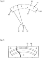
- FIG. 4 shows a banana or saber-shaped blank 66. It is cut from a sheet metal material. Steel sheet qualities and thicknesses are used as in the prior art.
- the blank 66 is delimited by circular arc lines which have a radius of curvature corresponding to the finished rail. Laterally, the blanks are bounded by longitudinal edges 67 in the form of radial lines. As FIG. 4 shows, lie the centers of curvature 44 substantially on a plane extending in the plane of the paper, which corresponds to the later center line 46. The centers of curvature 44 are distributed over a length corresponding to the thickness of the blank 66. The radius deviates from the radius of curvature by less than 3%.
- the blank has short transverse edges 69.
- FIG. 5 If a part of an embossing mold 68 is shown, only a principal view is shown.
- the embossing mold 68 is associated with a corresponding counter-mold, this is not shown.
- the embossing of the blank 66 can take place in a single embossing mold 68 with die and male, but it is also possible to carry out a plurality of embossing steps in different embossing dies 68.
- the blank 66 is inserted into the embossing mold 68, it is then added the counter-mold and carried out the embossing process.
- a production of the rail 22, 24 by stepwise shaping along the course of curvature is possible, such a method would be for example a rolling or bending.
- FIG. 6 shows a perspective view of a blank 66 from which an outer rail is to be made. It is intended for attachment to a component that extends substantially in the xy plane.
- the blank 66 is already bent so that it follows a cylinder jacket whose axis is determined by the midpoint line 46 (with a maximum deviation of 3% of the radius length).
- the longitudinal edges 67 now run along a circular arc with a radius that differs from the radius of curvature 42 by a maximum of 3%.
- the transverse edge 69 runs parallel to the midpoint line 46.
- FIG. 7 is a first bending step performed.
- first legs 73 have been angled parallel to the two longitudinal edges 67 and in their vicinity.
- a first bending line 79 runs along a circular arc with a radius that differs from the radius of curvature 42 by a maximum of 3%.
- FIG. 8 shows the state after a second bending step along second bending lines 81, these lie within the first bending lines 79 of the first bending step, second legs 74 are angled. Due to the bending steps, the used high-strength material has been discarded, it has easily discarded and twisted. The irregularities are eliminated by a calibration step.
- the calibration step is also referred to as a compensation step or correction bending step.
- the first leg 73 and / or the second leg 74 are each bent over in the opposite direction to the previous respective bending step and plastically deformed, that the faults are reduced and the outer surface of the respective leg 73, 74 has a regular, smooth course.
- the inner rail is created in the same way as the outer rail, this will be described below, however, more than two bending steps are carried out.
- 92 generally designates a bendline.
- FIG. 9 shows the rectangular blank 76 of the inner rail, it is already curved as well as the blank 66 for the outer rail.
- FIG. 10 shows the blank 76 after performing a first bending step, while first outer leg 78 are formed. It was bent along a third bending line 83, it runs along a circular arc with a radius which differs from the radius of curvature 42 by a maximum of 3%.
- FIG. 11 shows, second outer legs 80 are formed, which are inside of the first outer leg 78.
- FIG. 12 shows, third outer legs 82 are bent out of the plane of the blank 76, lying inside the second outer legs 80.
- each bending step which was described for the outer rail and the inner rail, takes place in each case about a circular arc line having a radius which differs from the radius of curvature 42 by a maximum of 3%.
- the blank 71 for the outer rail has a plurality of detent openings 86 which are arranged periodically in the longitudinal direction one behind the other.
- Each blank 71, 76 has attachment means 30 which are here formed as holes. With their help, the rail can run directly to a substantially in the xy plane Component of the floor assembly to be screwed. The screws used in this case run in the z-direction.
- the blank 76 for the inner rail has pin holes 90, here individual locking pins of a multi-pin lock are passed, as for example from the EP 1 316 465 B1 is known.
- FIG. 14 schematically shows a bending device, as they are alternative to the embossing mold 68 according to FIG. 5 can be used to a blank 66 accordingly FIG. 4 which is curved banana or saber-shaped, gradually deform into a splint.
- the bender has a base 94 from which two parallel bending bars 96 project upwardly. They form a bending line 92 with their upper, smooth edges. This extends on a circular arc with the radius 98, this radius 98 differs by a maximum of 3% of the radius of curvature 42. Its center is above the base 94, the radius 98 is parallel to the plane of the base 94.
- the bending bars 96 form bending lines 92.
- a blank 66 has already been placed on the upper edges of the bending bars 96, a first bending process has been carried out along the bending lines 92, a first leg 73 has been created on both sides.
- Bend line 92 extends near the longitudinal edge 67.
- the intermediate state achieved, as well as the final rail, is hinged symmetrically to an axis 100 which is perpendicular to the base flange 48 of the later rail.
- a bending mold for the production of the rails according to the Figures 6-13 differs from the bending form according to FIG. 14 as follows:
- the bending bars are now straight. They stay parallel to each other.
- the distance of the bending line from the base 94 is no longer constant, as in FIG. 14 but changes, he is still on a circular arc.
- the radius 98 now runs at right angles to the base 94, in the plane of the bending bar.
Landscapes
- Engineering & Computer Science (AREA)
- Mechanical Engineering (AREA)
- Aviation & Aerospace Engineering (AREA)
- Transportation (AREA)
- Seats For Vehicles (AREA)
- General Engineering & Computer Science (AREA)
Description
- Die Erfindung bezieht sich auf ein Kraftfahrzeug nach dem Oberbegriff des Anspruchs 1 und auf ein Verfahren zur Herstelllung. Ein derartiger Kraftfahrzeugsitz ist aus der
GB 2 071 486 A JP H01 87042 U DE 42 38 486 A1 , dort beispielsweiseFigur 2 , vorbekannt. Weitere Schienenführungen sind bekannt ausUS 5,941,495 A undDE 10 2006 048 786 A1 . Zudem wird aufDE 10 2006 047 525 A1 verwiesen. - Bei geradlinig verlaufenden Schienen besteht der Nachteil, dass bei einer Verstellung der Sitz im Raum lediglich linear bewegt wird, nicht aber weitere Bewegungen möglich sind. Ein großer Passagier stellt den Sitz weit nach hinten und tief nach unten, in der Regel neigt er auch zudem die Rückenlehne stärker gegenüber der Vertikalen nach hinten als ein kleinerer Passagier, der seinen Sitz weiter nach vorn und höher einstellt. Die Neigung der Rückenlehne kann nach dem Stand der Technik nur durch ein separates Rückenlehnengelenk verstellt werden. Wenn man ein solches vorsieht, bedeutet dies aber einen gewissen Aufwand. Auch die Neigung der Sitzfläche wird unterschiedlich gewählt von großen und kleinen Personen. Um die Neigung der Sitzfläche einstellen zu können, gibt es Sitzneigungsverstellungen. Diese bieten eine gute Bequemlichkeit, bedeuten aber wiederum Aufwand. Häufig wird auch eine Höhenverstellung vorgesehen, mit der die Höhe der Sitzfläche verstellt werden kann. Diese und jede andere zusätzliche Verstelleinrichtung bedeuten grundsätzlich ein Mehrgewicht und einen Aufwand an Material und in der Montage.
- Hier setzt nun die Erfindung ein. Sie hat es sich zur Aufgabe gemacht, ein Kraftfahrzeug der eingangs genannten Art so weiterzubilden, dass aufgrund seiner Schienenführung er von sich aus für die gesamte Bandbreite der Passagiere eine möglichst gute Einstellung liefert, so dass zusätzliche Einstellvorrichtungen über die Längsverstellung hinaus soweit wie möglich entfallen können. Dabei soll die Schienenführung nach wie vor einfach aufgebaut sein, sie soll den Ansprüchen, die man an eine Schienenführung nach dem Stand der Technik stellt, standhalten. Sie soll sich für manuelle und motorische Verstellvorrichtungen eignen.
- Diese Aufgabe wird gelöst durch die Merkmale des Anspruchs 1.
- Die Verstellrichtung verläuft entlang des Verschiebewegs auf einer Kreisbogenlinie. Aufgrund der speziellen Wahl der Krümmungsradien innerhalb der angegebenen Grenzen wird erreicht, dass ein weit hinten in der Schienenführung befindlicher Sitz etwas schräger nach hinten und zudem tiefer positioniert ist als ein im vorderen Bereich der Schienenführung eingestellter Sitz. Dies ermöglicht es, auf zusätzliche Einstellvorrichtungen, beispielsweise eine Sitzhöhenverstellung und/oder eine Neigungsverstellung der Rückenlehne, zu verzichten. Dies bedeutet eine erhebliche Einsparung von Gewicht. Auf diese Weise lässt sich ein Kraftfahrzeugsitz deutlich leichtgewichtiger ausbilden als nach dem Stand der Technik.
- Die einer Kreisbogenlinie folgende Krümmung hat einen Krümmungsmittelpunkt, der sich im eingebauten Zustand des Kraftfahrzeugsitzes unterhalb dieses Sitzes befindet. Der Krümmungsmittelpunkt befindet sich auf der Seite der Schienenführung, die von dem Sitzbereich und der Lehne abgewandt ist.
- Schienen mit einem derartigen Krümmungsradius lassen sich präzise fertigen. Trotz der nicht mehr linearen Verschiebung werden ein guter Gleichlauf, eine präzise Führung und eine hohe Fertigungsgenauigkeit erreicht. Nach wie vor ist eine der beiden Schienen vorzugsweise die umklammernde Schiene, die andere die umklammerte Schiene. Vorzugsweise liegen die beiden Schienen mit elastischer Vorspannung aneinander an. Die beiden Schienen liegen mittels Roll-oder Gleitkörpern aneinander an. Diese bilden die Führungsmittel. Aufgrund dieser Elastizität werden Fertigungsungenauigkeiten ausgeglichen und die Führungsmittel in ihrer Position gehalten. Die Schienen sind beide jeweils mindestens 25 cm lang, eine der beiden Schienen ist mindestens 30 cm lang. Vorzugsweise werden die Schienen aus einem Stahlblech mit einer Streckgrenze von mindestens 600 N/mm2 gefertigt. Dadurch können Bleche mit einer Dicke z.B. von 1,5 mm verwendet werden. Der Dickenbereich ist 1,2 bis 1,8 mm, vorzugsweise 1,5 + 10% und -30 %. Je dünner das Blech, umso geringer das Gewicht der Schiene.
- Vorzugsweise werden beide Schienen als Stanz-Biegeteil jeweils einzeln gefertigt. Dabei wird ausgegangen von einem Zuschnitt aus Stahlblech, insbesondere Breitband. Dieser Zuschnitt ist länglich, er ist entweder bananen- bzw. säbelförmig, wenn die Schiene so montiert werden soll, dass ein Basisflansch in der x-z-Ebene liegt, oder im Wesentlichen rechteckförmig, wenn die Schiene so montiert werden soll, dass ein Basisflansch in der x-y-Ebene liegt. Dieser Zuschnitt wird vorzugsweise in mehreren einzelnen Biegeschritten jeweils um zwei parallelle Biegelinien gebogen. Diese werden durch Biegeleisten realisiert. Es werden Biegungen entlang und in Nähe von den Längskanten durchgeführt. Vorzugsweise ist das Profil der fertigen Schiene klappsymmetrisch oder im Wesentlichen klappsymmetrisch zu einer Achse, die eine Mittelsenkrechte zum Basisflansch ist.
- Vorzugsweise wird zur Herstellung einer Schiene, die so montiert werden soll, dass der Basisflansch in der x-y-Ebene liegt, wie folgt verfahren: In einem ersten Bearbeitungsschritt wird der Zuschnitt gebogen, wobei die Biegelinie einen Radius aufweist, der mit dem Krümmungsradius übereinstimmt oder um bis zu 3% abweicht. Der Mittelpunkt befindet sich in Nähe der oder auf der Mittelpunktlinie, diese verläuft parallel zu den kurzen Kanten des Zuschnitts. Der Zuschnitt folgt dann einem Zylindermantel. In einem zweiten Biegeschritt werden dann links und rechts parallel zu der jeweiligen Längskante des Zuschnitts je ein seitlicher erster Schenkel gebogen. Dies erfolgt um eine Biegelinie, die auf einem Kreisbogen liegt. Die Biegelinie weist einen Radius auf, der vom Krümmungsradius um bis zu 3% abweichen kann. Er stimmt in der Regel nicht mit dem Krümmungsradius überein. Sein Mittelpunkt befindet sich in Nähe der oder auf der Mittelpunktlinie. In mindestens einem weiteren Biegeschritt wird mindestens ein weiterer Schenkel gebogen. Hier wird wie beim zweiten Biegeschritt verfahren. Bei der Herstellung einer Schiene, die so montiert werden soll, dass der Basisflansch in der x-z-Ebene liegt, entfällt der erste Bearbeitungsschritt und wird gleich mit dem zweiten Biegeschritt begonnen.
- Aufgrund der Verwendung von hochfestem Stahlmaterial und durch die Biegeschritte bedingt tritt ein Verzug bzw. eine Verwerfung auf. Die Schenkel und ggf. auch der Basisflansch der späteren Schiene zeigen Unregelmäßigkeiten, sie verlaufen nicht exakt auf einer Zylindermantelfläche bzw. einer glatten, regelmäßig gekrümmten Fläche. Umso hochfester der Stahl ist, also umso größer die Streckgrenze ist, umso größer sind auch die inneren Spannungen im Material bei den Biegeschritten und damit die Verwerfungen. Deshalb muss nach mindestens einem Biegeschritt, vorzugsweise nach zwei oder drei Biegeschritten ein Ausgleich der Verwerfungen und Spannungen erfolgen. Dies erfolgt in einem Kalibrierschritt. Dabei wird die Schiene begradigt. Der Verzug wird beseitigt. Dies geschieht dadurch, dass zur Gegenseite, also in Gegenrichtung der vorherigen Biegerichtung, überbogen wird. Dabei wird eine plastische Deformation durchgeführt. Die seitliche Flanke wird auf diese Weise begradigt. Gegebenenfalls wird auch ein anderer Bereich begradigt.
- Die Verbiegungen erfolgen dadurch, dass Biegeleisten an den Zuschnitt angelegt werden und um die Biegeleisten gebogen wird. Die Biegeleisten haben eine Krümmung um den Krümmungsmittel mit einer Abweichung im Radius von unter +/- 3% vom Krümmungsradius. Es werden Biegeschritte durchgeführt, wie dies auch bei gradlinig verlaufenden Schienen durchgeführt wird. Es werden nun aber Biegeleisten verwendet, die nicht gradlinig verlaufen, sondern um den Biegeradius gekrümmt.
- Vorzugsweise ist der Schienenführung ein Stellantrieb für die Längsverstellung zugeordnet. Dieser Stellantrieb hat vorzugsweise einen Drehantrieb, der eine Ausgangswelle und ein Getriebe hat, das eine Spindelmutter, die mit der Ausgangswelle drehverbunden ist und eine Spindel aufweist, dabei weist die Spindel ein Spindelgewinde auf, mit dem die Spindelmutter in Eingriff ist, die Spindel ist in demselben kreisförmigen Krümmungsradius wie die Schienen gekrümmt, die Spindelmutter ist eine gerade Mutter.
- Vorzugsweise ist der Kraftfahrzeugsitz mit einer motorischen Verstellvorrichtung ausgerüstet, die für die Verstellung entlang des Verschiebeweges sorgt. Der Drehantrieb kann auch für eine manuelle Verstellung ausgelegt sein. Der Drehantrieb ist dann von Hand zu betätigen. Er weist z.B. eine Kurbel auf, die sich in Griffweite eines Passagiers befindet und über die der Passagier die Drehbewegung in das Getriebe einleitet. Im Gegensatz zu einer Schienenführung nach dem Stand der Technik, die ohne Drehantrieb und mit einer manuell zu betätigenden Arretiereinrichtung ausgestattet ist, wird keine Feder benötigt, die den Sitz innerhalb seiner Schienenführung nach vorn belastet. Diese Feder muss eine erhebliche Federkraft aufweisen, sie trägt zum Gesamtgewicht bei. Eine derartige Feder wird eingespart.
- Es ist auch Aufgabe der Erfindung, ein Verfahren zum Herstellen einer derartigen Schienenführung anzugeben. Gemäß diesem Verfahren werden die Bodenschiene und die Sitzschiene jeweils aus einem geeigneten Zuschnitt hergestellt, dieser Zuschnitt verläuft entlang der Krümmungsradien, den die fertige Schiene hat. Die Zuschnitte werden in mindestens einer jeweiligen Prägeform geprägt, das Prägen findet in zumindest einem Prägeschritt statt. Auf diese Weise wird die fertige Schiene erstellt.
- Dieses Verfahren hat den Vorteil, dass die gewünschten Genauigkeiten erreicht werden. Es lassen sich auf diese Weise Schienen herstellen, die trotz des gekrümmten Verlaufs des Verschiebeweges leicht verstellbar sind, präzise ineinander geführt sind und gute Gleiteigenschaften aufweisen.
- Üblicherweise hat eine Längsverstellung zwei Schienenführungen, die weitgehend baugleich sind. Bei einem Kraftfahrzeugsitz mit zwei Schienenführungen sind beide Schienenführungen um denselben Krümmungsradius gebogen.
- Die Bodenschiene weist vorzugsweise Befestigungsbereiche auf, an diesen ist sie mit einer Bodengruppe des Kraftfahrzeugs verbindbar.
- Bei dem Kraftfahrzeugsitz weist das Sitzgestell Verbindungsteile auf, die Verbindungsteile sind vorzugsweise mit den Mitteln zur Befestigung der beiden Sitzschienen jeder Seite verbunden.
- Vorzugsweise hat ein derartiger Kraftfahrzeugsitz keine weitere Einstellvorrichtung, insbesondere keine Sitzhöhenverstellung und/oder keine Lehnenneigungsverstellung.
- Im Kraftfahrzeug ist die Schienenführung so angeordnet, dass in der hintersten Position der Längsverstellung die Lehne des Kraftfahrzeugsitzes in einem Winkel von 10 bis 15° gemessen von der Vertikalen nach hinten geneigt ist und in der vordersten Position in einem Winkel von 5 bis 10°, wiederum gemessen von der Vertikalen nach hinten geneigt ist, wobei die Winkeländerung zwischen diesen beiden Positionen mindestens 4°, vorzugsweise 6° beträgt. Dabei werden die gewünschten Verstellpositionen unmittelbar über die Schienenführung erreicht, ohne dass zusätzliche Einstellvorrichtungen vorhanden sind. Dies führt zu einem deutlichen Kosten- und Gewichtsvorteil.
- Bei dem Kraftfahrzeugsitz ist der Sitzbereich vorzugsweise starr mit den Schienen verbunden. Es sind vorzugsweise keine Einstellvorrichtungen zwischen der Sitzschiene und dem Sitzbereich vorgesehen. Dadurch werden Bauteile einer normalerweise vorhandenen Sitzhöhenverstellung und/oder Sitzneigungsverstellung eingespart. Zu diesen Bauteilen gehört beispielsweise eine sitzanhebende Feder, die eine gewisse Federkraft haben muss, was ein beträchtliches Gewicht bedeutet, es werden Gelenkarme und Einstellvorrichtungen, beispielsweise Taumelgelenkbeschläge, eingespart.
- Vorzugsweise liegen alle Krümmungsmittelpunkte von Teilbereichen der Schienen und ggf. einer zugeordneten, gekrümmten Spindel auf einer Mittelpunktlinie, die eine Parallele zur y-Achse ist. Die einzelnen Radien verlaufen senkrecht zu dieser Mittelpunktlinie. Ihre Mittelpunkte liegen auf der Mittelpunktslinie. Bei einer Längsführung mit zwei Schienenführungen liegen die Krümmungsmittelpunkte beider Schienenführungen auf derselben Mittelpunktlinie, allerdings an unterschiedlichen Orten auf dieser. Bei jeder einzelnen Schiene einer Schienenführung liegen die Zentren der Krümmungsradien der Kanten auf der Mittelpunktlinie. Sie haben dort denselben Abstand voneinander, wie sie in der Schiene selbst in y-Richtung beabstandet sind. Die Krümmungsradien unterschiedlicher Teilbereiche der Schienen sind unterschiedlich. Sie verlaufen konzentrisch zueinander. Dies gilt insbesondere für die Teilbereiche einer Schiene, die in Kontakt mit der anderen Schiene sind.
- Weitere Vorteile und Merkmale der Erfindung ergeben sich aus den übrigen Ansprüchen sowie der folgenden Beschreibung eines nicht einschränkend zu verstehenden Ausführungsbeispiels der Erfindung, das unter Bezugnahme auf die Zeichnung im Folgenden näher erläutert wird. In dieser Zeichnung zeigen:
- Fig. 1:
- eine prinzipielle Seitenansicht auf einen Kraftfahrzeugsitz mit einer gekrümmten Schienenführung,
- Fig. 2:
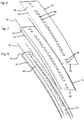
- eine perspektivische Darstellung in Form eines Montagebildes einer Schienenführung mit zusätzlichem Spindelantrieb,
- Fig. 3:
- einen Axialschnitt durch eine Spindel eines Spindelantriebs mit Spindelmutter, Gehäuse und Zubehör, gezeigt ist nur der Bereich um die Spindelmutter herum,
- Fig. 4:
- eine Draufsicht auf einen Zuschnitt für eine Schiene,
- Fig. 5:
- eine prinzipielle Darstellung einer Prägeform mit Draufsicht auf den Formhohlraum,
- Fig. 6:
- eine perspektivische Ansicht eines Zuschnitts für eine Außenschiene,
- Fig. 7
- den Zuschnitt nach
Fig. 6 nach einer ersten Biegestufe, - Fig. 8
- den Zuschnitt nach
Fig. 6 nach einer zweiten Biegestufe, - Fig. 9:
- eine perspektivische Ansicht eines Zuschnitts für eine Innenschiene,
- Fig. 10
- den Zuschnitt nach
Fig. 9 nach einer ersten Biegestufe, - Fig. 11
- den Zuschnitt nach
Fig. 9 nach einer zweiten Biegestufe, - Fig. 12
- den Zuschnitt nach
Fig. 9 nach einer dritten Biegestufe, - Fig. 13
- den Zuschnitt nach
Fig. 9 nach einer vierten Biegestufe und - Fig. 14
- eine schematische, perspektivische Darstellung einer Biegeform, wie sie für die Herstellung der Schienen nach
Fig. 1 und 3 alternaitiv zu der Prägeform gem.Fig. 5 verwendet werden kann. - Der in
Figur 1 dargestellte Kraftfahrzeugsitz ist in zwei unterschiedlichen Extrempositionen dargestellt, nämlich in ausgezogenen Strichen in einer hintersten Position und strichpunktiert in einer vordersten Position. Beide Positionen werden entlang eines Verschiebeweges 20 erreicht, der auf einem Kreisbogen verläuft. - In bekannter Weise hat der Kraftfahrzeugsitz mindestens ein Schienenpaar, das eine Bodenschiene 22, eine Sitzschiene 24 und Führungsmittel 26 aufweist. Im gezeigten Ausführungsbeispiel sind zwei parallel zueinander angeordnete Schienenführungen vorgesehen. Sie sind im Ausführungsbeispiel baugleich. Die Führungsmittel 26 sind als Kugeln ausgebildet, andere Ausbildungen sind möglich. Die Bodenschiene 22 ist im Wesentlichen C-förmig. Sie ist als umgreifende Schiene ausgebildet. Sie hat Mittel für eine Befestigung an einer Bodengruppe 28 eines sonst nicht näher dargestellten Kraftfahrzeugs. Die Sitzschiene 24 ist eine umgriffene Schiene, auch sie ist im Wesentlichen C-förmig. Sie hat Mittel 30, die hier als Öffnungen ausgebildet sind, sie dienen der Verbindung mit einem vorderen Verbindungsteil 32 und einem hinteren Verbindungsteil 34 für jede Sitzseite. Diese Verbindungsteile 32, 34 tragen einen Sitzbereich 36. Dieser ist starr mit der Sitzschiene 24 verbunden. Es ist eine Lehne 38 vorgesehen. Wie
Figur 1 zeigt, sind keine Mittel für eine Sitzneigungsverstellung, Sitzhöhenverstellung und Neigungsverstellung der Lehne 38 vorgesehen. - Für die Beschreibung wird ein rechtshändiges x-y-z-Koordinatensystem verwendet. Die x-Achse und die y-Achse liegen in der Horizontalen. Die x-Achse zeigt in die Richtung normaler Geradeausfahrt des Kraftfahrzeugs. Die z-Achse ist parallel zu einer Vertikalen.
- Die beiden Schienen 22, 24 jeder Schienenführung begrenzen einen kanalförmigen Hohlraum 40. Er ist nur in x-Richtung offen.
- Die Bodenschiene 22 und die Sitzschiene 24 sind um den jeweils gleichen, kreisförmigen Krümmungsradius gekrümmt. Der Verschiebeweg 20 hat mindestens eine Länge von 150 mm und maximal eine Länge von 350 mm. Vorzugsweise liegt der Verschiebeweg 20 im Bereich von 250 bis 300 mm. De Krümmungsradius R 42 liegt zwischen 1.500 und 3.000 mm, insbesondere zwischen 1.800 und 2.500 mm. Ein Krümmungsmittelpunkt 44 liegt auf einer Mittelpunktlinie 46, die eine Parallele zur y-Achse ist. Die Krümmungsradien 42 für die einzelnen Kanten einer Schiene 22 bzw. 24 haben unterschiedliche Längen und auch unterschiedliche Krümmungsmittelpunkte. Alle Krümmungsmittelpunkte liegen auf einer Mittelpunktlinie 46. Die Radien verlaufen jeweils senkrecht zur Mittelpunktlinie 46, dies ist in
Fig. 2 durch ein entsprechendes Symbol angegeben. Die Krümmungsmittelpunkte 44 zweier unterschiedlicher Längskanten einer Schiene 22 bzw. 24 haben in der Schiene selbst denselben Abstand in y-Richtung wie auf der Mittelpunktlinie 46. Jede Schiene 22 bzw. 24 hat über ihre Länge gesehen einen konstanten Querschnitt. Der Querschnitt wird auf einer Querschnittsebene ermittelt, die Mittelpunktlinie 46 liegt in der jeweiligen Querschnittsebene. Die einzelnen Querschnittsebenen stehen in einem Winkel zueinander. - Beide Schienen 22, 24 haben jeweils einen Basisflansch 48. Dieser Basisflansch verläuft in einer Ebene, die parallel zur x-z-Ebene ist. Der Basisflansch 48 hat die Form eines Kreisscheibensektors.
- Die beiden Schienenpaare des Kraftfahrzeugsitzes sind lediglich in y-Richtung zueinander versetzt, in x-Richtung und in z-Richtung haben sie übereinstimmende Koordinaten. Der Versatz in y-Richtung entspricht mindestens der halben Breite des Sitzbereichs und ist maximal 120% der Breite in y-Richtung des Sitzbereichs.
-
Figur 1 zeigt den Zustand des im Kraftfahrzeug (nicht dargestellt) eingebauten Kraftfahrzeugsitzes. In diesem Einbauzustand ist das hintere Ende der Schienen 20, 22 der tiefste Punkt. Die Bezeichnung vorn entspricht der positiven Richtung der x-Richtung und oben entspricht der positiven Richtung der z-Achse. - Die Schienenführung ist im Kraftfahrzeug nach vorn ansteigend angeordnet. Eine Tangente angelegt an den vordersten Bereich der Bodenschiene 22 verläuft im Wesentlichen parallel zur x-y-Ebene. Die Tangente weicht von dieser Ebene vorzugsweise nur ±° 5, insbesondere nur ±° 3 ab.
- In einer vordersten Stellung ist der Sitzbereich 36 um einen Winkel gegenüber der horizontalen x-y-Ebene nach hinten geneigt, der bei etwa 3° liegt. Der Winkelbereich kann 0 bis 6° betragen. Innerhalb des Verschiebeweges 20 wird eine Winkeländerung 50 um etwa 10° erreicht. Diese Winkeländerung kann zwischen 4 und 12° liegen.
- Im Ausführungsbeispiel ist die Länge der vorderen Verbindungsteile 32 etwas geringer, beispielsweise 5 bis 30% geringer, als die Länge der hinteren Verbindungsteile 34. Die vorderen Verbindungsteile 32 jeder Sitzseite und ebenfalls die hinteren Verbindungsteile 34 jeder Sitzseite sind in Längsrichtung, die im Wesentlichen mit der z-Richtung übereinstimmt, gleich lang.
- Die Mittelpunktlinie 46 ist der Ort der Krümmungsmittelpunkte 44. Diese befinden sich unterhalb der Schienenführung und damit auf der anderen Seite der Schienenführung als der Sitzbereich 36 und die Lehne 38.
- Es ist eine motorische Verstellvorrichtung vorgesehen, die eine Verstellung des Kraftfahrzeugsitzes innerhalb des Verschiebeweges 20 ermöglicht. Sie hat in an sich bekannter Weise eine Spindel 52, die drehfest an ihren Enden über Halter mit der Bodenschiene 22 verbunden ist. Im Unterschied zum Stand der Technik ist die Spindel 52 entlang einer Kreislinie gekrümmt. Diese Kreislinie hat einen Krümmungsradius, der den Krümmungsradius der Schienen 22, 24 entspricht. Der Krümmungsmittelpunkt liegt auf der Mittelpunktlinie 46. Verwendet werden Spindeln mit einem Durchmesser von 6 bis 10 mm, beispielsweise eine Spindel mit M8-Gewinde. In an sich bekannter Weise wird die Spindel 52 von einer Spindelmutter 54 umgriffen. Diese Spindelmutter 54 ist gerade. Sie hat eine Länge von 10 bis 20 mm. Vorzugsweise wird sie kurz gewählt. Eine Länge von 10 bis 15 mm ist bevorzugt. Die Spindelmutter 54 ist eine Mutter nach dem Stand der Technik. Vorzugsweise hat die Spindelmutter 54 jedoch an jeder axialen Seite einen Anfangsbereich 56, der kegelförmig oder anderweitig nach außen erweiternd ausgebildet ist. Aufgrund der Anfangsbereiche 56 wird einem Verkanten der Spindelmutter 54 entgegengewirkt.
- In an sich bekannter Weise ist an der Spindelmutter ein äußeres Schneckenrad ausgebildet, das in Eingriff mit einer Schnecke 58 ist. Diese ist über eine elastische Ausgangswelle 70 mit einem Elektromotor 60 verbunden. Der Elektromotor 60 ist für beide Sitzseiten zuständig, er ist über eine weitere elastische Welle mit der Schienenführung der anderen Sitzseite verbunden. Dies ist Stand der Technik.
- In einer bevorzugten Alternative wird anstelle eines Elektromotors ein Handantrieb eingesetzt, hier findet beispielsweise eine Handkurbel Verwendung. Diese kann unterhalb der Sitzvorderkante angeordnet sein und eine im Wesentlichen in x-Richtung verlaufende Drehachse haben. Sie ist über elastische Wellen mit den beiden Sitzseiten verbunden.
- Die Spindelmutter 54 und die Schnecke 58 sind in einem Gehäuse 62 untergebracht. Das Gehäuse 62 wird von einer Klammer 64 umgriffen, die im Wesentlichen U-förmig ist. Sie hat Befestigungsbereiche, diese sind mit der Sitzschiene 24 verbunden, hierzu hat die Sitzschiene 24 Befestigungslöcher. In der Mitte zwischen den beiden Befestigungslöchern befindet sich ein Durchlass der Sitzschiene 24 für die elastische Ausgangswelle 70.
- Im Folgenden wird nun ein erstes Verfahren zur Herstellung der Sitzschiene 22, 24 beschrieben, wie sie für das Ausführungsbeispiel nach
Fig. 1 und 3 geeignet ist, also für eine Befestigung an einem Bauteil, das im Wesentlichen in der x-y-Ebene verläuft. -
Figur 4 zeigt einen bananen- bzw. säbelförmigen Zuschnitt 66. Er ist aus einem Blechmaterial zugeschnitten. Verwendet werden Stahlblechqualitäten und - dicken wie im Stand der Technik. Im Unterschied zum Stand der Technik ist der Zuschnitt 66 durch Kreisbogenlinien begrenzt, die einem Krümmungsradius entsprechend der fertigen Schiene aufweisen. Seitlich sind die Zuschnitte durch Längskanten 67 in Form von radialen Linien begrenzt. WieFigur 4 zeigt, liegen die Krümmungsmittelpunkte 44 im Wesentlichen auf einer in der Papierebene verlaufenden Linie, die der späteren Mittelpunktlinie 46 entspricht. Die Krümmungsmittelpunkte 44 verteilen sich über eine Länge, die der Dicke des Zuschnitts 66 entspricht. Der Radius weicht vom Krümmungsradius um weniger als 3% ab. Der Zuschnitt hat kurze Querkanten 69. - In
Figur 5 ist ein Teil einer Prägeform 68 dargestellt, gezeigt ist nur eine prinzipielle Ansicht. Die Prägeform 68 ist eine entsprechende Gegenform zugeordnet, diese ist nicht dargestellt. Das Prägen des Zuschnitts 66 kann in einer einzigen Prägeform 68 mit Matrize und Patrize erfolgen, es können aber auch mehrere Prägeschritte in unterschiedlichen Prägeformen 68 durchgeführt werden. Der Zuschnitt 66 wird in die Prägeform 68 eingelegt, es wird dann die Gegenform hinzugefügt und der Prägevorgang durchgeführt. - Eine Herstellung der Schiene 22, 24 durch schrittweises Formen entlang des Krümmungsverlaufs ist möglich, ein derartiges Verfahren wäre beispielsweise ein Rollen oder Biegen.
- Ein weiteres Verfahren wird nun unter Bezugnahme auf die
Figuren 6-8 und9-13 beschrieben.Figur 6 zeigt eine perspektivische Ansicht eines Zuschnitts 66, aus dem eine Außenschiene hergestellt werden soll. Sie ist für eine Befestigung an einem Bauteil, das im Wesentlichen in der x-y-Ebene verläuft, bestimmt. Der Zuschnitt 66 ist bereits so gebogen, das er einem Zylindermantel folgt, dessen Achse durch die Mittelpunktslinie 46 (mit einer maximalen Abweichung von 3% der Radiuslänge) bestimmt ist. Anders ausgedrückt verlaufen die Längskanten 67 nun entlang eines Kreisbogens mit einem Radius, der vom Krümmungsradius 42 um maximal 3% abweicht. Die Querkante 69 verläuft parallel zur Mittelpunktslinie 46. - In
Figur 7 ist eine erste Biegestufe durchgeführt. Dabei sind erste Schenkel 73 parallel zu den beiden Längskanten 67 und in deren Nähe abgewinkelt worden. Eine erste Biegelinie 79 verläuft entlang eines Kreisbogens mit einem Radius, der vom Krümmungsradius 42 um maximal 3% abweicht. -
Figur 8 zeigt den Zustand nach einem zweiten Biegeschritt entlang zweiten Biegelinien 81, diese liegen innerhalb der ersten Biegelinien 79 des ersten Biegeschrittes, es werden zweite Schenkel 74 abgewinkelt. Durch die Biegeschritte hat sich das verwendete hochfeste Material verworfen, es hat sich leicht verworfen und verdrillt. Die Unregelmäßigkeiten werden durch einen Kalibrierschritt beseitigt. Der Kalibrierschritt wird auch als Ausgleichsschritt oder Korrekturbiegeschritt bezeichnet. Hierbei werden der erste Schenkel 73 und/oder der zweite Schenkel 74 jeweils so in Gegenrichtung zum vorangegangenen jeweiligen Biegeschritt überbogen und plastisch deformiert, dass die Verwerfungen abgebaut werden und die Außenfläche des jeweiligen Schenkels 73, 74 einen regelmäßigen, glatten Verlauf hat. - Entsprechend wie die Außenschiene wird die Innenschiene erstellt, dies wird im Folgenden beschrieben, es werden allerdings mehr als zwei Biegeschritte durchgeführt. Mit 92 wird allgemein eine Biegelinie bezeichnet.
-
Figur 9 zeigt den rechteckförmigen Zuschnitt 76 der Innenschiene, er ist bereits ebenso wie der Zuschnitt 66 für die Außenschiene gekrümmt. -
Figur 10 zeigt den Zuschnitt 76 nach Durchführen eines ersten Biegeschritts, dabei sind erste Außenschenkel 78 ausgebildet. Gebogen wurde entlang einer dritten Biegelinie 83, sie verläuft entlang eines Kreisbogens mit einem Radius, der vom Krümmungsradius 42 um maximal 3% abweicht. Nach einem zweiten Biegeschritt, denFigur 11 zeigt, sind zweite Außenschenkel 80 gebildet, die innseitig der ersten Außenschenkel 78 liegen. Nach einem dritten Biegeschritt, denFigur 12 zeigt, sind dritte Außenschenkel 82 aus der Ebene des Zuschnitts 76 ausgebogen, sie liegen innseitig der zweiten Außenschenkel 80. - In einem vierten und letzten Biegeschritt, den
Figur 13 zeigt, sind vierte Außenschenkel 84 erstellt, sie liegen innseitig der dritten Außenschenkel 82. Jeder Biegeschritt, der für die Außenschiene und die Innenschiene beschrieben wurde, erfolgt jeweils um eine Kreisbogenlinie mit einem Radius, der vom Krümmungsradius 42 um maximal 3% abweicht. - Der Zuschnitt 71 für die Außenschiene hat eine Vielzahl von Rastöffnungen 86, die in Längsrichtung hintereinander periodisch angeordnet sind. Jeder Zuschnitt 71, 76 hat Befestigungsmittel 30, die hier als Löcher ausgebildet sind. Mit ihrer Hilfe kann die Schiene direkt an einem im Wesentlichen in der x-y-Ebene verlaufenden Bauteil der Bodengruppe angeschraubt werden. Die dabei verwendeten Schrauben verlaufen in der z-Richtung. Der Zuschnitt 76 für die Innenschiene hat Stiftlöcher 90, hier werden einzelne Sperrstifte einer Vielstiftverriegelung hindurchgeführt, wie sie beispielsweise aus dem
EP 1 316 465 B1 bekannt ist. -
Figur 14 zeigt schematisch eine Biegevorrichtung, wie sie alternativ zur Prägeform 68 gemäßFigur 5 eingesetzt werden kann, um einen Zuschnitt 66 entsprechendFigur 4 , der bananen- bzw. säbelförmig gekrümmt ist, schrittweise in eine Schiene zu verformen. Die Biegevorrichtung hat eine Basis 94, von der zwei parallele Biegeleisten 96 nach oben wegstehen. Sie bilden mit ihren oberen, glatten Kanten eine Biegelinie 92 aus. Diese verläuft auf einem Kreisbogen mit dem Radius 98, dieser Radius 98 unterscheidet sich um maximal 3% vom Krümmungsradius 42. Sein Zentrum liegt oberhalb der Basis 94, der Radius 98 verläuft parallel zur Ebene der Basis 94. Die Biegeleisten 96 bilden Biegelinien 92 aus. Auf die Oberkanten der Biegeleisten 96 ist bereits ein Zuschnitt 66 aufgelegt, es ist ein erster Biegevorgang entlang der Biegelinien 92 durchgeführt worden, es ist ein erster Schenkel 73 beidseitig erstellt worden. Die Biegelinie 92 verläuft in Nähe der Längskante 67. Der erreichte Zwischenzustand ist wie auch die finale Schiene klappsymmetrisch zu einer Achse 100, die eine Mittelsenkrechte zum Basisflansch 48 der späteren Schiene ist. - Eine Biegeform für die Herstellung der Schienen gemäß den
Figuren 6-13 unterscheidet sich von der Biegeform gemäßFigur 14 wie folgt: Die Biegeleisten verlaufen nun gradlinig. Sie bleiben parallel zueinander. Der Abstand der Biegelinie von der Basis 94 ist nicht mehr konstant, wie beiFigur 14 , sondern ändert sich, er liegt nach wie vor auf einem Kreisbogen. Der Radius 98 läuft nun rechtwinklig zur Basis 94, in der Ebene der Biegeleiste. -
- 20
- Verschiebeweg
- 22
- Bodenschiene
- 24
- Sitzschiene
- 26
- Führungsmittel
- 28
- Bodengruppe
- 30
- Mitte (Loch 88 Befestigungsmittel)
- 32
- vorderes Verbindungsteil
- 34
- hinteres Verbindungsteile
- 36
- Sitzbereich
- 38
- Lehne
- 40
- Hohlraum
- 42
- Krümmungsradius
- 44
- Krümmungsmittelpunkt
- 46
- Mittelpunktlinie
- 48
- Basisflansch
- 50
- Winkeländerung
- 52
- Spindel
- 54
- Spindelmutter
- 56
- Anfangsbereich
- 58
- Schnecke
- 60
- Elektromotor
- 62
- Gehäuse
- 64
- Klammer
- 66
- Zuschnitt
- 67
- Längskante
- 68
- Prägeform
- 69
- Querkante
- 70
- Ausgangswelle
- 71
- Zuschnitt für Außenschiene
- 72
- Hohlraum
- 73
- erster Innenschenkel
- 74
- zweiter Innenschenkel
- 76
- Zuschnitt für Innenschiene
- 78
- erster Außenschenkel
- 80
- zweiter Außenschenkel
- 82
- dritter Außenschenkel
- 84
- vierter Außenschenkel
- 86
- Rastöffnung
- 90
- Stiftlöcher
- 94
- Basis
- 96
- Biegeleiste
- 98
- Radius
- 100
- Achse
Claims (8)
- Kraftfahrzeug, mit einem an einer Bodengruppe (28) befestigten Kraftfahrzeugsitz,- mit einem Sitzgestell, das einen Sitzbereich (36) aufweist, und- mit einer Längsverstellvorrichtung, die eine Schienenführung mit mindestens einem Schienenpaar hat, das eine an der Bodengruppe befestigte Bodenschiene (22), eine Sitzschiene (24) und zwischen diesen beiden Schienen angeordnete Führungsmittel (26) aufweist, wobei die Schienen des Schienenpaars in einer Längsrichtung, die im Wesentlichen parallel zu einer x-Achse ist, gegeneinander entlang eines Verschiebewegs (20) verschiebbar sind und die Sitzschiene (24) Mittel (30) zur Befestigung des oberhalb des Schienenpaars anzuordnenden Sitzgestells aufweist, wobei die Bodenschiene (22) und die Sitzschiene (24) um den jeweils gleichen, kreisförmigen Krümmungsradius (42) gekrümmt sind und der Krümmungsmittelpunkt (44) sich auf der dem Sitzgestell abgewandten Seite des Schienenpaars befindet,dadurch gekennzeichnet, dass der Krümmungsradius (42) zwischen 1.500 und 3.000 mm, insbesondere zwischen 1.800 und 2.500 mm liegt, und dass eine Tangente angelegt an den vordersten Bereich der Bodenschiene (22) im Wesentlichen parallel zur x-y-Ebene verläuft und von dieser Ebene vorzugsweise nur ± 5°, insbesondere nur ± 3° abweicht.
- Kraftfahrzeug nach dem vorangegangenen Anspruch, dadurch gekennzeichnet, dass der Krümmungsmittelpunkt (44) sich auf einer Ebene befindet, die parallel zur x-z-Ebene ist und durch die Mitte des Schienenpaars verläuft.
- Kraftfahrzeug nach einem der vorangegangenen Ansprüche, dadurch gekennzeichnet, dass in einer vordersten Stellung der Sitzbereich (36) um einen Winkel gegenüber der horizontalen x-y-Ebene nach hinten geneigt ist, der im Bereich von 0 bis 6° liegt.
- Kraftfahrzeug nach einem der vorangegangenen Ansprüche, dadurch gekennzeichnet, dass die Mittel (30) zur Befestigung des Sitzgestells vordere Verbindungsteile (32) und hintere Verbindungsteile (34) aufweisen, und dass die vorderen Verbindungsteile (32) eine 5 bis 30% geringere Länge als die Länge der hinteren Verbindungsteile 34 aufweisen, und/oder dass die vorderen Verbindungsteile (32) jeder Sitzseite und die hinteren Verbindungsteile (34) jeder Sitzseite in Längsrichtung, die im Wesentlichen mit der z-Richtung übereinstimmt, gleich lang sind.
- Kraftfahrzeug nach einem der vorangegangenen Ansprüche, dadurch gekennzeichnet, dass die Längsverstellvorrichtung weiterhin einen Stellantrieb aufweist, dass der Stellantrieb a) einen Drehantrieb, insbesondere einen Elektromotor, der eine Ausgangswelle hat, b) ein Getriebe, das eine Spindelmutter hat, die mit der Ausgangswelle drehverbunden ist und c) eine Spindel aufweist, dass die Spindel ein Spindelgewinde aufweist, mit dem die Spindelmutter in Eingriff ist, dass die Spindel in demselben kreisförmigen Krümmungsradius (42) wie die Schienen gekrümmt ist, und dass die Spindelmutter eine gerade Mutter ist.
- Kraftfahrzeug nach einem der Ansprüche 1 bis 5, dadurch gekennzeichnet, dass der Kraftfahrzeugsitz keine Sitzneigungsverstellung und Sitzhöhenverstellung hat und keine Neigungsverstellung einer Lehne (38) hat, und dass auf ein in einer horizontalen Ebene befindliches Fahrzeug bezogen, die Lehne in der hintersten Position der Längsverstellung in einem Winkel von 10 bis 15° gemessen von der Vertikalen nach hinten geneigt ist und in der vordersten Position der Sitzverstellung in einem Winkel von 5 bis 10° gemessen von der Vertikalen nach hinten geneigt ist, wobei die Winkeländerung (50) zwischen diesen beiden Positionen mindestens 4°, vorzugsweise etwa 6° beträgt.
- Verfahren zum Herstellen eines Kraftfahrzeugs nach einem der vorangegangenen Ansprüche, dadurch gekennzeichnet, dass die Bodenschiene (22) aus einem Bodenschienenzuschnitt und die Sitzschiene (24) aus einem Sitzschienenzuschnitt gefertigt werden, dass die Zuschnitte jeweils um den Krümmungsradius (42) der Schiene gekrümmt verlaufen, dass die Zuschnitte in mindestens einer jeweiligen Prägeform (68) geprägt werden, die einen gekrümmte Verlauf aufweist, wobei der Verlauf in demselben kreisförmigen Krümmungsradius (42) wie die Schienen gekrümmt ist, und dass durch Prägen in mindestens einem Schritt die fertige Bodenschiene (22) bzw. Sitzschiene (24) erstellt wird.
- Verfahren zum Herstellen eines Kraftfahrzeugs nach einem der Ansprüche 1 bis 6 , dadurch gekennzeichnet, dass die Bodenschiene (22) aus einem Bodenschienenzuschnitt und die Sitzschiene (24) aus einem Sitzschienenzuschnitt gefertigt werden, dass die Zuschnitte aus Stahlblech hergestellt werden und länglich sind, wobei a) die Längskanten (67) des Zuschnitts dann, wenn ein Basisflansch (48) im fertigen Fahrzeug in der x-y-Ebene liegt, geradlinig verlaufen und der Zuschnitt einem Zylindermantel entsprechend gebogen ist und b) die Längskanten (67) des Zuschnitts dann, wenn ein Basisflansch (48) im fertigen Fahrzeug in der x-z-Ebene liegt, gekrümmt verlaufen und der Zuschnitt eben ist, dass der Zuschnitt in mindestens einem Biegeschritt um jeweils um zwei parallele Biegeleisten (96) um Biegelinien (83, 92) gebogen wird, die jeweils im Wesentlichen parallel zu einer Längskante (67) verlaufen, und dass mindestens ein Kalibrierschritt durchgeführt wird, bei dem in Gegenrichtung zur Biegung des mindestens einen Biegeschrittes zurückgebogen wird.
Applications Claiming Priority (2)
| Application Number | Priority Date | Filing Date | Title |
|---|---|---|---|
| DE102011080221 | 2011-08-01 | ||
| PCT/EP2012/065064 WO2013017633A1 (de) | 2011-08-01 | 2012-08-01 | Schienenführung für eine längsverstellung eines kraftfahrzeugsitzes und verfahren zur herstellung einer derartigen schienenführung |
Publications (2)
| Publication Number | Publication Date |
|---|---|
| EP2739504A1 EP2739504A1 (de) | 2014-06-11 |
| EP2739504B1 true EP2739504B1 (de) | 2018-10-10 |
Family
ID=46642502
Family Applications (1)
| Application Number | Title | Priority Date | Filing Date |
|---|---|---|---|
| EP12745816.4A Active EP2739504B1 (de) | 2011-08-01 | 2012-08-01 | Kraftfahrzeug und verfahren zur herstellung eines solchen kraftfahrzeugs |
Country Status (6)
| Country | Link |
|---|---|
| US (1) | US9050907B2 (de) |
| EP (1) | EP2739504B1 (de) |
| JP (1) | JP5826389B2 (de) |
| KR (2) | KR101863939B1 (de) |
| CN (1) | CN103717444B (de) |
| WO (1) | WO2013017633A1 (de) |
Families Citing this family (20)
| Publication number | Priority date | Publication date | Assignee | Title |
|---|---|---|---|---|
| WO2013017632A2 (de) * | 2011-08-01 | 2013-02-07 | C. Rob. Hammerstein Gmbh & Co. Kg | Stellantrieb für eine schienenführung einer längsverstellung eines kraftfahrzeugsitzes |
| DE102013105095B4 (de) * | 2013-02-14 | 2018-05-30 | Adient Luxembourg Holding S.À R.L. | Verstellvorrichtung für einen Fahrzeugsitz |
| CN103909841B (zh) * | 2014-04-23 | 2016-07-20 | 上海延锋江森座椅有限公司 | 汽车座椅滑轨机构 |
| US10384567B2 (en) * | 2014-11-12 | 2019-08-20 | Ts Tech Co., Ltd. | Vehicle seat |
| DE102016204503B4 (de) | 2015-04-01 | 2022-05-12 | Adient Luxembourg Holding S.À R.L. | Fahrzeugsitz mit Längseinstellvorrichtung |
| US9745066B2 (en) * | 2015-09-03 | 2017-08-29 | Ami Industries, Inc. | Adjustable seat assembly |
| CN105835728B (zh) * | 2016-05-12 | 2018-03-27 | 浙江龙生汽车部件科技有限公司 | 一种带解锁限位结构的车用手动滑轨 |
| GB201619544D0 (en) | 2016-11-18 | 2017-01-04 | Mclaren Automotive Ltd | Seat adjustment mechanism |
| DE102016225053B4 (de) * | 2016-12-14 | 2025-07-10 | Brose Fahrzeugteile SE & Co. Kommanditgesellschaft, Coburg | Verstelleinrichtung für die Längsverstellung eines Fahrzeugsitzes |
| US10155548B2 (en) * | 2017-03-14 | 2018-12-18 | Ford Global Technologies, Llc | Vehicle structure including reinforcement extending between rockers |
| DE102017003686B4 (de) * | 2017-04-15 | 2020-07-09 | Audi Ag | Fahrersitz für ein Zweirad |
| DE102017117846A1 (de) * | 2017-08-07 | 2019-02-07 | Faurecia Autositze Gmbh | Vorrichtung und Verfahren zur Verstellung eines Sitzes |
| DE102017122754A1 (de) * | 2017-09-29 | 2019-04-04 | MAX-PLANCK-Gesellschaft zur Förderung der Wissenschaften e.V. | Vorrichtung sowie Vakuumkammer |
| US11833933B2 (en) | 2019-03-04 | 2023-12-05 | Adient Us Llc | Longitudinal adjusting device for the motorized longitudinal adjustment of a vehicle seat, and vehicle seat |
| FR3099891B1 (fr) * | 2019-08-14 | 2021-07-23 | Cooper Standard France | Rail de guidage, dispositif et procédé de moulage par injection de ce rail. |
| DE102020102867B4 (de) * | 2019-10-02 | 2024-08-22 | Keiper Seating Mechanisms Co., Ltd. | Längseinsteller für einen fahrzeugsitz und fahrzeugsitz |
| CN111674298B (zh) * | 2020-06-17 | 2022-05-13 | 中国第一汽车股份有限公司 | 一种座椅滑轨机构及汽车 |
| KR102448459B1 (ko) * | 2020-07-22 | 2022-09-29 | 현대자동차주식회사 | 차량의 시트 조립체 |
| EP4493430A1 (de) * | 2022-12-27 | 2025-01-22 | Pilot Tasit Koltuklari Sanayi Ve Ticaret Anonim Sirketi | Seitenisolator für fahrzeugsitze |
| CN117124942B (zh) * | 2023-10-25 | 2024-01-23 | 今创集团股份有限公司 | 一种自锁装置、锁定机构及电动旋转座椅 |
Family Cites Families (24)
| Publication number | Priority date | Publication date | Assignee | Title |
|---|---|---|---|---|
| GB2071486A (en) * | 1980-02-22 | 1981-09-23 | Cox T I Ltd | Vehicle seat slides |
| FR2544415B1 (fr) | 1983-04-15 | 1986-09-05 | Peugeot Cycles | Element de glissiere a billes et glissiere ainsi realisee |
| JPS60121938U (ja) * | 1984-01-27 | 1985-08-17 | 池田物産株式会社 | 車輛用シ−トのパワ−スライド装置 |
| JPS60180638U (ja) * | 1984-05-11 | 1985-11-30 | アラコ株式会社 | 車両用フロントシ−ト |
| JPH0187042U (de) | 1987-12-01 | 1989-06-08 | ||
| JPH0737023Y2 (ja) | 1989-02-22 | 1995-08-23 | 自動車電機工業株式会社 | パワーウインド装置 |
| DE4000555A1 (de) | 1990-01-10 | 1991-07-11 | Walter Dipl Ing Dr Ing Mehnert | Getriebeanordnung |
| DE4238486A1 (de) | 1992-04-27 | 1993-10-28 | Hammerstein Gmbh C Rob | Längsführung für Längsverstelleinrichtungen von Fahrzeugsitzen |
| DE19521566B4 (de) | 1995-06-19 | 2008-07-10 | C. Rob. Hammerstein Gmbh & Co. Kg | Längsführung für einen Fahrzeugsitz mit zwei Schienen und zwischen diesen angeordneten Führungsmitteln |
| JPH1190534A (ja) | 1997-09-18 | 1999-04-06 | Pacific Ind Co Ltd | 形状凍結性に優れた弓形プレス成形品の成形方法 |
| DE19815283C2 (de) * | 1998-04-06 | 2000-07-13 | Brose Fahrzeugteile | Spindelantrieb für Verstelleinrichtungen in Kraftfahrzeugen |
| DE50211512D1 (de) | 2001-11-28 | 2008-02-21 | Hammerstein Gmbh C Rob | Arretiervorrichtung mit gerillten Sperrstiften |
| JP4078199B2 (ja) * | 2002-12-20 | 2008-04-23 | プレス工業株式会社 | 折り曲げ品の製造方法及び製造装置 |
| DE102004013009B4 (de) * | 2004-03-16 | 2008-03-20 | Ims Gear Gmbh | Antrieb für eine Verstelleinrichtung innerhalb eines Fahrzeuges, insbesondere eine Sitzverstelleinrichtung innerhalb eines Kraftfahrzeuges und Verfahren zur Herstellung eines solchen Antriebs |
| JP4264054B2 (ja) | 2004-06-01 | 2009-05-13 | 株式会社神戸製鋼所 | 曲げ成形方法およびその成形方法に用いる成形金型 |
| DE102004063932B4 (de) | 2004-09-21 | 2013-03-28 | Ims Gear Gmbh | Getriebe und Fahrzeugsitz mit einem solchen Getriebe |
| JP2006305627A (ja) | 2005-03-28 | 2006-11-09 | Kobe Steel Ltd | 湾曲状チャンネル部材の成形方法 |
| DE102006047525A1 (de) | 2005-10-27 | 2007-05-03 | C. Rob. Hammerstein Gmbh & Co. Kg | Arretiervorrichtung einer Längsverstellvorrichtung eines Kraftfahrzeugsitzes mit zwei Schienenpaaren |
| DE102006048786A1 (de) | 2005-11-14 | 2007-05-24 | C. Rob. Hammerstein Gmbh & Co. Kg | Schienenpaar einer Längsführung eines Kraftfahrzeugsitzes |
| US8226063B2 (en) * | 2006-10-23 | 2012-07-24 | Intier Automotive Inc | Power seat track drive assembly |
| DE102007027322A1 (de) * | 2007-06-14 | 2008-12-18 | Brose Fahrzeugteile Gmbh & Co. Kommanditgesellschaft, Coburg | Schienenverstellsystem für einen Kraftfahrzeugsitz |
| JP5293026B2 (ja) * | 2008-09-12 | 2013-09-18 | アイシン精機株式会社 | 車両用パワーシート装置 |
| EP2305512B1 (de) * | 2009-10-05 | 2014-01-01 | Delta Kogyo Co., Ltd. | Sitzschienenstruktur für ein Fahrzeug |
| DE102011011315A1 (de) * | 2011-02-15 | 2012-08-16 | Brose Fahrzeugteile Gmbh & Co. Kommanditgesellschaft, Coburg | Sitzschiene für Kraftfahrzeugsitze |
-
2012
- 2012-08-01 EP EP12745816.4A patent/EP2739504B1/de active Active
- 2012-08-01 KR KR1020167007120A patent/KR101863939B1/ko active Active
- 2012-08-01 KR KR1020147005605A patent/KR20140034328A/ko not_active Ceased
- 2012-08-01 WO PCT/EP2012/065064 patent/WO2013017633A1/de not_active Ceased
- 2012-08-01 JP JP2014523319A patent/JP5826389B2/ja active Active
- 2012-08-01 CN CN201280038106.XA patent/CN103717444B/zh active Active
- 2012-08-01 US US14/236,507 patent/US9050907B2/en active Active
Non-Patent Citations (1)
| Title |
|---|
| None * |
Also Published As
| Publication number | Publication date |
|---|---|
| JP2014521555A (ja) | 2014-08-28 |
| JP5826389B2 (ja) | 2015-12-02 |
| WO2013017633A1 (de) | 2013-02-07 |
| US20140175249A1 (en) | 2014-06-26 |
| CN103717444B (zh) | 2016-08-10 |
| KR20160036636A (ko) | 2016-04-04 |
| CN103717444A (zh) | 2014-04-09 |
| US9050907B2 (en) | 2015-06-09 |
| KR101863939B1 (ko) | 2018-07-04 |
| EP2739504A1 (de) | 2014-06-11 |
| KR20140034328A (ko) | 2014-03-19 |
Similar Documents
| Publication | Publication Date | Title |
|---|---|---|
| WO2013017633A1 (de) | Schienenführung für eine längsverstellung eines kraftfahrzeugsitzes und verfahren zur herstellung einer derartigen schienenführung | |
| DE102012103038B4 (de) | Vorrichtung zur Gurtführung an einem Gurtintegralsitz | |
| EP3007928B1 (de) | Fahrzeugsitzunterkonstruktion mit einer unfallinduzierten verstellvorrichtung | |
| EP2739503B1 (de) | Schienenführung einer längsverstellung eines kraftfahrzeugsitzes | |
| EP3271209B1 (de) | Längseinsteller für einen fahrzeugsitz | |
| DE102013221542B4 (de) | Fahrzeugsitz mit Fangelement | |
| WO2019243176A1 (de) | Baugruppe mit einer mit einer bodenbaugruppe verbundenen führungsschiene | |
| DE102018117118A1 (de) | Schiene für Fahrzeugsitz und Fahrzeugsitz umfassend eine solche Schiene | |
| DE102008021802B4 (de) | Türführung eines Fahrzeuges und Verfahren zu deren Herstellung | |
| DE102019104530B3 (de) | Führungseinrichtung zum Führen einer Verstellbewegung eines Fahrzeugsitzes | |
| EP1193119B1 (de) | Rahmenstruktur, insbesondere Lehnenrahmen für einen Fahrzeugstuhl, umfassend wenigstens zwei Seitenholme und einen diese verbindenden oberen Querträger, jeweils aus Hohlprofilen | |
| DE3301309A1 (de) | Verstellvorrichtung fuer fahrzeug-sitze | |
| EP2523827A1 (de) | Führungsmittel mit toleranzkompensation für vernähung von dekorelementen | |
| DE102006014719B4 (de) | Trägerprofil und Befestigungsanordnung eines Sitzuntergestells an einer Bodenanlage eines Omnibusses | |
| DE102007010064A1 (de) | Fahrzeugsitz mit einer Kopfstütze | |
| EP1721770A2 (de) | Führungsschiene für ein Kfz-Schiebedachsystem | |
| DE102019215725A1 (de) | Fensterheberbaugruppe mit Einstellelement | |
| DE102018121478A1 (de) | Verkleidungselement, umfassend eine verformbare Außenfläche | |
| DE102011119551A1 (de) | Sitzanlage,insbesondere Fahrzeugsitz, für einen Kraftwagen | |
| WO2012163551A1 (de) | Aufnahmevorrichtung für eine kopfstütze an der lehne eines sitzes, insbesondere eines kraftfahrzeugsitzes | |
| WO2019025343A1 (de) | Befestigungseinheit zum beweglichen befestigen einer luftfahrzeugkomponente an einer tragstruktur eines luftfahrzeugs | |
| EP2740636B1 (de) | Schlitten für eine Höhenverstellung eines schulternahen Ankerpunktes eines Fahrzeugrückhaltesystems | |
| DE102004010488B4 (de) | Längseinsteller für einen Fahrzeugsitz | |
| DE102010055181B4 (de) | Fertigungsverfahren sowie Seitenteil der Struktur eines Fahrzeugsitzes | |
| DE102017207358A1 (de) | Fahrzeugsitz mit einer Verstellkinematik |
Legal Events
| Date | Code | Title | Description |
|---|---|---|---|
| PUAI | Public reference made under article 153(3) epc to a published international application that has entered the european phase |
Free format text: ORIGINAL CODE: 0009012 |
|
| 17P | Request for examination filed |
Effective date: 20140303 |
|
| AK | Designated contracting states |
Kind code of ref document: A1 Designated state(s): AL AT BE BG CH CY CZ DE DK EE ES FI FR GB GR HR HU IE IS IT LI LT LU LV MC MK MT NL NO PL PT RO RS SE SI SK SM TR |
|
| RAP1 | Party data changed (applicant data changed or rights of an application transferred) |
Owner name: JOHNSON CONTROLS METALS AND MECHANISMS GMBH & CO. |
|
| DAX | Request for extension of the european patent (deleted) | ||
| RAP1 | Party data changed (applicant data changed or rights of an application transferred) |
Owner name: ADIENT LUXEMBOURG HOLDING S.A R.L. |
|
| GRAP | Despatch of communication of intention to grant a patent |
Free format text: ORIGINAL CODE: EPIDOSNIGR1 |
|
| STAA | Information on the status of an ep patent application or granted ep patent |
Free format text: STATUS: GRANT OF PATENT IS INTENDED |
|
| INTG | Intention to grant announced |
Effective date: 20180214 |
|
| RAP1 | Party data changed (applicant data changed or rights of an application transferred) |
Owner name: ADIENT LUXEMBOURG HOLDING S.A R.L. |
|
| GRAS | Grant fee paid |
Free format text: ORIGINAL CODE: EPIDOSNIGR3 |
|
| GRAJ | Information related to disapproval of communication of intention to grant by the applicant or resumption of examination proceedings by the epo deleted |
Free format text: ORIGINAL CODE: EPIDOSDIGR1 |
|
| GRAL | Information related to payment of fee for publishing/printing deleted |
Free format text: ORIGINAL CODE: EPIDOSDIGR3 |
|
| GRAJ | Information related to disapproval of communication of intention to grant by the applicant or resumption of examination proceedings by the epo deleted |
Free format text: ORIGINAL CODE: EPIDOSDIGR1 |
|
| GRAL | Information related to payment of fee for publishing/printing deleted |
Free format text: ORIGINAL CODE: EPIDOSDIGR3 |
|
| STAA | Information on the status of an ep patent application or granted ep patent |
Free format text: STATUS: REQUEST FOR EXAMINATION WAS MADE |
|
| GRAR | Information related to intention to grant a patent recorded |
Free format text: ORIGINAL CODE: EPIDOSNIGR71 |
|
| STAA | Information on the status of an ep patent application or granted ep patent |
Free format text: STATUS: GRANT OF PATENT IS INTENDED |
|
| INTG | Intention to grant announced |
Effective date: 20180214 |
|
| INTC | Intention to grant announced (deleted) | ||
| INTG | Intention to grant announced |
Effective date: 20180625 |
|
| GRAA | (expected) grant |
Free format text: ORIGINAL CODE: 0009210 |
|
| STAA | Information on the status of an ep patent application or granted ep patent |
Free format text: STATUS: THE PATENT HAS BEEN GRANTED |
|
| AK | Designated contracting states |
Kind code of ref document: B1 Designated state(s): AL AT BE BG CH CY CZ DE DK EE ES FI FR GB GR HR HU IE IS IT LI LT LU LV MC MK MT NL NO PL PT RO RS SE SI SK SM TR |
|
| REG | Reference to a national code |
Ref country code: GB Ref legal event code: FG4D Free format text: NOT ENGLISH |
|
| REG | Reference to a national code |
Ref country code: CH Ref legal event code: EP Ref country code: AT Ref legal event code: REF Ref document number: 1050831 Country of ref document: AT Kind code of ref document: T Effective date: 20181015 |
|
| REG | Reference to a national code |
Ref country code: IE Ref legal event code: FG4D Free format text: LANGUAGE OF EP DOCUMENT: GERMAN |
|
| REG | Reference to a national code |
Ref country code: DE Ref legal event code: R096 Ref document number: 502012013588 Country of ref document: DE |
|
| REG | Reference to a national code |
Ref country code: NL Ref legal event code: MP Effective date: 20181010 |
|
| REG | Reference to a national code |
Ref country code: LT Ref legal event code: MG4D |
|
| PG25 | Lapsed in a contracting state [announced via postgrant information from national office to epo] |
Ref country code: NL Free format text: LAPSE BECAUSE OF FAILURE TO SUBMIT A TRANSLATION OF THE DESCRIPTION OR TO PAY THE FEE WITHIN THE PRESCRIBED TIME-LIMIT Effective date: 20181010 |
|
| PG25 | Lapsed in a contracting state [announced via postgrant information from national office to epo] |
Ref country code: IS Free format text: LAPSE BECAUSE OF FAILURE TO SUBMIT A TRANSLATION OF THE DESCRIPTION OR TO PAY THE FEE WITHIN THE PRESCRIBED TIME-LIMIT Effective date: 20190210 Ref country code: FI Free format text: LAPSE BECAUSE OF FAILURE TO SUBMIT A TRANSLATION OF THE DESCRIPTION OR TO PAY THE FEE WITHIN THE PRESCRIBED TIME-LIMIT Effective date: 20181010 Ref country code: LV Free format text: LAPSE BECAUSE OF FAILURE TO SUBMIT A TRANSLATION OF THE DESCRIPTION OR TO PAY THE FEE WITHIN THE PRESCRIBED TIME-LIMIT Effective date: 20181010 Ref country code: HR Free format text: LAPSE BECAUSE OF FAILURE TO SUBMIT A TRANSLATION OF THE DESCRIPTION OR TO PAY THE FEE WITHIN THE PRESCRIBED TIME-LIMIT Effective date: 20181010 Ref country code: NO Free format text: LAPSE BECAUSE OF FAILURE TO SUBMIT A TRANSLATION OF THE DESCRIPTION OR TO PAY THE FEE WITHIN THE PRESCRIBED TIME-LIMIT Effective date: 20190110 Ref country code: BG Free format text: LAPSE BECAUSE OF FAILURE TO SUBMIT A TRANSLATION OF THE DESCRIPTION OR TO PAY THE FEE WITHIN THE PRESCRIBED TIME-LIMIT Effective date: 20190110 Ref country code: PL Free format text: LAPSE BECAUSE OF FAILURE TO SUBMIT A TRANSLATION OF THE DESCRIPTION OR TO PAY THE FEE WITHIN THE PRESCRIBED TIME-LIMIT Effective date: 20181010 Ref country code: LT Free format text: LAPSE BECAUSE OF FAILURE TO SUBMIT A TRANSLATION OF THE DESCRIPTION OR TO PAY THE FEE WITHIN THE PRESCRIBED TIME-LIMIT Effective date: 20181010 Ref country code: ES Free format text: LAPSE BECAUSE OF FAILURE TO SUBMIT A TRANSLATION OF THE DESCRIPTION OR TO PAY THE FEE WITHIN THE PRESCRIBED TIME-LIMIT Effective date: 20181010 |
|
| PG25 | Lapsed in a contracting state [announced via postgrant information from national office to epo] |
Ref country code: PT Free format text: LAPSE BECAUSE OF FAILURE TO SUBMIT A TRANSLATION OF THE DESCRIPTION OR TO PAY THE FEE WITHIN THE PRESCRIBED TIME-LIMIT Effective date: 20190210 Ref country code: AL Free format text: LAPSE BECAUSE OF FAILURE TO SUBMIT A TRANSLATION OF THE DESCRIPTION OR TO PAY THE FEE WITHIN THE PRESCRIBED TIME-LIMIT Effective date: 20181010 Ref country code: GR Free format text: LAPSE BECAUSE OF FAILURE TO SUBMIT A TRANSLATION OF THE DESCRIPTION OR TO PAY THE FEE WITHIN THE PRESCRIBED TIME-LIMIT Effective date: 20190111 Ref country code: SE Free format text: LAPSE BECAUSE OF FAILURE TO SUBMIT A TRANSLATION OF THE DESCRIPTION OR TO PAY THE FEE WITHIN THE PRESCRIBED TIME-LIMIT Effective date: 20181010 Ref country code: RS Free format text: LAPSE BECAUSE OF FAILURE TO SUBMIT A TRANSLATION OF THE DESCRIPTION OR TO PAY THE FEE WITHIN THE PRESCRIBED TIME-LIMIT Effective date: 20181010 |
|
| REG | Reference to a national code |
Ref country code: DE Ref legal event code: R097 Ref document number: 502012013588 Country of ref document: DE |
|
| PG25 | Lapsed in a contracting state [announced via postgrant information from national office to epo] |
Ref country code: CZ Free format text: LAPSE BECAUSE OF FAILURE TO SUBMIT A TRANSLATION OF THE DESCRIPTION OR TO PAY THE FEE WITHIN THE PRESCRIBED TIME-LIMIT Effective date: 20181010 Ref country code: IT Free format text: LAPSE BECAUSE OF FAILURE TO SUBMIT A TRANSLATION OF THE DESCRIPTION OR TO PAY THE FEE WITHIN THE PRESCRIBED TIME-LIMIT Effective date: 20181010 Ref country code: DK Free format text: LAPSE BECAUSE OF FAILURE TO SUBMIT A TRANSLATION OF THE DESCRIPTION OR TO PAY THE FEE WITHIN THE PRESCRIBED TIME-LIMIT Effective date: 20181010 |
|
| PLBE | No opposition filed within time limit |
Free format text: ORIGINAL CODE: 0009261 |
|
| STAA | Information on the status of an ep patent application or granted ep patent |
Free format text: STATUS: NO OPPOSITION FILED WITHIN TIME LIMIT |
|
| PG25 | Lapsed in a contracting state [announced via postgrant information from national office to epo] |
Ref country code: EE Free format text: LAPSE BECAUSE OF FAILURE TO SUBMIT A TRANSLATION OF THE DESCRIPTION OR TO PAY THE FEE WITHIN THE PRESCRIBED TIME-LIMIT Effective date: 20181010 Ref country code: SM Free format text: LAPSE BECAUSE OF FAILURE TO SUBMIT A TRANSLATION OF THE DESCRIPTION OR TO PAY THE FEE WITHIN THE PRESCRIBED TIME-LIMIT Effective date: 20181010 Ref country code: SK Free format text: LAPSE BECAUSE OF FAILURE TO SUBMIT A TRANSLATION OF THE DESCRIPTION OR TO PAY THE FEE WITHIN THE PRESCRIBED TIME-LIMIT Effective date: 20181010 Ref country code: RO Free format text: LAPSE BECAUSE OF FAILURE TO SUBMIT A TRANSLATION OF THE DESCRIPTION OR TO PAY THE FEE WITHIN THE PRESCRIBED TIME-LIMIT Effective date: 20181010 |
|
| 26N | No opposition filed |
Effective date: 20190711 |
|
| PG25 | Lapsed in a contracting state [announced via postgrant information from national office to epo] |
Ref country code: SI Free format text: LAPSE BECAUSE OF FAILURE TO SUBMIT A TRANSLATION OF THE DESCRIPTION OR TO PAY THE FEE WITHIN THE PRESCRIBED TIME-LIMIT Effective date: 20181010 |
|
| PG25 | Lapsed in a contracting state [announced via postgrant information from national office to epo] |
Ref country code: TR Free format text: LAPSE BECAUSE OF FAILURE TO SUBMIT A TRANSLATION OF THE DESCRIPTION OR TO PAY THE FEE WITHIN THE PRESCRIBED TIME-LIMIT Effective date: 20181010 |
|
| GBPC | Gb: european patent ceased through non-payment of renewal fee |
Effective date: 20190801 |
|
| PG25 | Lapsed in a contracting state [announced via postgrant information from national office to epo] |
Ref country code: LI Free format text: LAPSE BECAUSE OF NON-PAYMENT OF DUE FEES Effective date: 20190831 Ref country code: LU Free format text: LAPSE BECAUSE OF NON-PAYMENT OF DUE FEES Effective date: 20190801 Ref country code: CH Free format text: LAPSE BECAUSE OF NON-PAYMENT OF DUE FEES Effective date: 20190831 Ref country code: MC Free format text: LAPSE BECAUSE OF FAILURE TO SUBMIT A TRANSLATION OF THE DESCRIPTION OR TO PAY THE FEE WITHIN THE PRESCRIBED TIME-LIMIT Effective date: 20181010 |
|
| REG | Reference to a national code |
Ref country code: BE Ref legal event code: MM Effective date: 20190831 |
|
| PG25 | Lapsed in a contracting state [announced via postgrant information from national office to epo] |
Ref country code: IE Free format text: LAPSE BECAUSE OF NON-PAYMENT OF DUE FEES Effective date: 20190801 |
|
| PG25 | Lapsed in a contracting state [announced via postgrant information from national office to epo] |
Ref country code: BE Free format text: LAPSE BECAUSE OF NON-PAYMENT OF DUE FEES Effective date: 20190831 Ref country code: GB Free format text: LAPSE BECAUSE OF NON-PAYMENT OF DUE FEES Effective date: 20190801 |
|
| REG | Reference to a national code |
Ref country code: AT Ref legal event code: MM01 Ref document number: 1050831 Country of ref document: AT Kind code of ref document: T Effective date: 20190801 |
|
| PG25 | Lapsed in a contracting state [announced via postgrant information from national office to epo] |
Ref country code: AT Free format text: LAPSE BECAUSE OF NON-PAYMENT OF DUE FEES Effective date: 20190801 |
|
| PG25 | Lapsed in a contracting state [announced via postgrant information from national office to epo] |
Ref country code: CY Free format text: LAPSE BECAUSE OF FAILURE TO SUBMIT A TRANSLATION OF THE DESCRIPTION OR TO PAY THE FEE WITHIN THE PRESCRIBED TIME-LIMIT Effective date: 20181010 |
|
| REG | Reference to a national code |
Ref country code: DE Ref legal event code: R082 Ref document number: 502012013588 Country of ref document: DE Representative=s name: KUTZENBERGER WOLFF & PARTNER PATENTANWALTSPART, DE Ref country code: DE Ref legal event code: R082 Ref document number: 502012013588 Country of ref document: DE Representative=s name: LIEDTKE & PARTNER PATENTANWAELTE, DE Ref country code: DE Ref legal event code: R081 Ref document number: 502012013588 Country of ref document: DE Owner name: KEIPER SEATING MECHANISMS CO., LTD., CN Free format text: FORMER OWNER: ADIENT LUXEMBOURG HOLDING S.A R.L., LUXEMBOURG, LU Ref country code: DE Ref legal event code: R081 Ref document number: 502012013588 Country of ref document: DE Owner name: KEIPER SEATING MECHANISMS CO., LTD., CN Free format text: FORMER OWNER: ADIENT YANFENG SEATING MECHANISM CO., LTD, SHANGHAI, CN |
|
| PG25 | Lapsed in a contracting state [announced via postgrant information from national office to epo] |
Ref country code: HU Free format text: LAPSE BECAUSE OF FAILURE TO SUBMIT A TRANSLATION OF THE DESCRIPTION OR TO PAY THE FEE WITHIN THE PRESCRIBED TIME-LIMIT; INVALID AB INITIO Effective date: 20120801 Ref country code: MT Free format text: LAPSE BECAUSE OF FAILURE TO SUBMIT A TRANSLATION OF THE DESCRIPTION OR TO PAY THE FEE WITHIN THE PRESCRIBED TIME-LIMIT Effective date: 20181010 |
|
| PG25 | Lapsed in a contracting state [announced via postgrant information from national office to epo] |
Ref country code: MK Free format text: LAPSE BECAUSE OF FAILURE TO SUBMIT A TRANSLATION OF THE DESCRIPTION OR TO PAY THE FEE WITHIN THE PRESCRIBED TIME-LIMIT Effective date: 20181010 |
|
| REG | Reference to a national code |
Ref country code: DE Ref legal event code: R082 Ref document number: 502012013588 Country of ref document: DE Representative=s name: KUTZENBERGER WOLFF & PARTNER PATENTANWALTSPART, DE |
|
| PGFP | Annual fee paid to national office [announced via postgrant information from national office to epo] |
Ref country code: FR Payment date: 20250610 Year of fee payment: 14 |
|
| PGFP | Annual fee paid to national office [announced via postgrant information from national office to epo] |
Ref country code: DE Payment date: 20250604 Year of fee payment: 14 |