EP2738461B1 - Solid fuel burner - Google Patents
Solid fuel burner Download PDFInfo
- Publication number
- EP2738461B1 EP2738461B1 EP12820064.9A EP12820064A EP2738461B1 EP 2738461 B1 EP2738461 B1 EP 2738461B1 EP 12820064 A EP12820064 A EP 12820064A EP 2738461 B1 EP2738461 B1 EP 2738461B1
- Authority
- EP
- European Patent Office
- Prior art keywords
- guide member
- combustion gas
- secondary combustion
- burner
- nozzle
- Prior art date
- Legal status (The legal status is an assumption and is not a legal conclusion. Google has not performed a legal analysis and makes no representation as to the accuracy of the status listed.)
- Active
Links
Images


Classifications
-
- F—MECHANICAL ENGINEERING; LIGHTING; HEATING; WEAPONS; BLASTING
- F23—COMBUSTION APPARATUS; COMBUSTION PROCESSES
- F23B—METHODS OR APPARATUS FOR COMBUSTION USING ONLY SOLID FUEL
- F23B99/00—Subject matter not provided for in other groups of this subclass
-
- F—MECHANICAL ENGINEERING; LIGHTING; HEATING; WEAPONS; BLASTING
- F23—COMBUSTION APPARATUS; COMBUSTION PROCESSES
- F23D—BURNERS
- F23D1/00—Burners for combustion of pulverulent fuel
-
- F—MECHANICAL ENGINEERING; LIGHTING; HEATING; WEAPONS; BLASTING
- F23—COMBUSTION APPARATUS; COMBUSTION PROCESSES
- F23D—BURNERS
- F23D14/00—Burners for combustion of a gas, e.g. of a gas stored under pressure as a liquid
- F23D14/46—Details, e.g. noise reduction means
- F23D14/72—Safety devices, e.g. operative in case of failure of gas supply
- F23D14/78—Cooling burner parts
-
- F—MECHANICAL ENGINEERING; LIGHTING; HEATING; WEAPONS; BLASTING
- F23—COMBUSTION APPARATUS; COMBUSTION PROCESSES
- F23D—BURNERS
- F23D2201/00—Burners adapted for particulate solid or pulverulent fuels
- F23D2201/10—Nozzle tips
-
- F—MECHANICAL ENGINEERING; LIGHTING; HEATING; WEAPONS; BLASTING
- F23—COMBUSTION APPARATUS; COMBUSTION PROCESSES
- F23D—BURNERS
- F23D2201/00—Burners adapted for particulate solid or pulverulent fuels
- F23D2201/20—Fuel flow guiding devices
-
- F—MECHANICAL ENGINEERING; LIGHTING; HEATING; WEAPONS; BLASTING
- F23—COMBUSTION APPARATUS; COMBUSTION PROCESSES
- F23D—BURNERS
- F23D2214/00—Cooling
-
- F—MECHANICAL ENGINEERING; LIGHTING; HEATING; WEAPONS; BLASTING
- F23—COMBUSTION APPARATUS; COMBUSTION PROCESSES
- F23D—BURNERS
- F23D2900/00—Special features of, or arrangements for burners using fluid fuels or solid fuels suspended in a carrier gas
- F23D2900/00016—Preventing or reducing deposit build-up on burner parts, e.g. from carbon
Definitions
- the present invention relates to a solid fuel burner for burning a solid fuel such as coal.
- a large circulating flow is formed between a mixture fluid of pulverized coal and carrier gas and secondary and tertiary air flows (combustion air flow) by ejecting the tertiary air flow outside the mixture fluid of pulverized coal and carrier gas and ejecting the secondary air flow outwardly beyond the tertiary air flow, whereby the mixing of the pulverized coal and the combustion air in the furnace in the vicinity of the burner outlet can be suppressed to effectively reduce the NOx generation and the unburned combustible contents in burnt ash, maintaining stable pulverized coal ignition and flame stability.
- a structure in which, for the purpose of cooling a flame stabilizing ring disposed at an outlet of a primary sleeve through which a mixture fluid of pulverized coal and carrier gas flows, the flame stabilizing ring and a part of the primary sleeve connected to the flame stabilizing ring are both made into a two-tiered cooling sleeve, and a fin is provided in the cooling sleeve so that the flame stabilizing ring can be cooled by air flowing through the cooling sleeve.
- a pilot nozzle is provided at the center of a burner body and a plurality of main nozzles are arranged at intervals around the pilot nozzle so as to use a flame ejected from the pilot nozzle for ignition of a fuel ejected from the main nozzles
- an end of a gas nozzle has a cooling structure with an air cooling fin so as to prevent temperature from rising due to radiant heat from a furnace.
- a guide plate for making the jet angle of the secondary air flow larger than the jet angle of the tertiary air flow is provided at an end of a partition between a pulverized coal nozzle and a secondary air nozzle.
- the guide plate directly receives radiation from the furnace, it may be burnt.
- Patent Literature 2 in which the flame stabilizing ring is cooled by the air flowing through the cooling sleeve of the solid fuel burner, meanwhile, since the fin is also provided in the cooling sleeve, the flame stabilizing ring can be effectively cooled.
- the cooling air ejected into the furnace from the flame stabilizing ring may interfere with the formation of the circulating flow composed of hot air and pulverized coal in the vicinity of the flame stabilizing ring and downstream of the flame stabilizing ring.
- the burner disclosed in Patent Literature 3 is a gas turbine burner
- the flame reducing zone (circulating flow) for stabilizing flame is formed downstream of the collar disposed at the end of the tapered part spreading in a radial fashion from the outlet of the pilot nozzle toward the main nozzles, and moreover, the air passage leading to the tapered part is provided in the collar so as to cool the collar.
- the circulation zone downstream of the collar is made large without consideration of deposition of ash. Therefore, ash may easily deposit on the collar when the burner structure is employed for a solid fuel such as coal.
- the solid fuel ignites slower than a gas fuel, employing the above burner structure may result in retarding the ignition.
- Patent Literature 4 which has a cooling device between a secondary air and a tertiary air, meanwhile, slugs are cracked and removed by thermal shock not only with a cooling air flowing through a slit provided at an end of the cooling device but also with different materials used for the members located inside and outside the slit.
- the cooling air coming out of the slit is ejected toward the center axis (fuel jet side) and its flow is obstructed by the secondary air flow, it is estimated that a sufficient amount of secondary air necessary for cooling cannot flow. Therefore, presumably, the deposited slugs have to be cracked by using the different materials.
- the flow from the slit and the secondary air flow (or fuel jet) may interfere with each other to make unstable the ignition of the burner and the flame.
- the present invention adopts the following solutions.
- a preferential embodiment provides a solid fuel burner according to the first or second aspect of the present invention, characterized in that the second guide member (35) has an inner diameter which is smaller than an outer diameter of the first guide member (34) and an outer diameter which is larger than the outer diameter of the first guide member (34).
- the flow 17b of the secondary combustion gas flow 17 at the furnace-facing front side of the second guide member 35 which is a part of the secondary combustion gas flow 17 rectified by the fin members 36, is ejected along the flame stabilizing sleeve 23b, and the first guide member 34 is disposed at the end of the flame stabilizing sleeve 23b, so that the front side of the second guide member 35 can be cooled by the secondary combustion gas flow 17b, rectified by the fin member 36, flowing toward the front side (furnace side) of the second guide member 35 through the gap between the second guide member 35 and the flame stabilizer 23, which also prevents deposition of ash and the like on the second guide member 35.
- a relatively small circulating flow 19b can be formed downstream of the second guide member 35 to draw in a hot gas from the furnace, while a relatively large circulating flow 19a can be formed at the front side (furnace-facing side) of the first and the second guide members 34, 35, wherein these circulating flows 19a, 19b may draw in a hot gas from the furnace, so that the fuel ignition and flaming stability can be maintained to effectively reduce the NO X concentration and the unburned combustible contents in burnt ash.
- the outward angles of the first guide member 34 and the second guide member 35 with respect to the burner center axis are larger than the outward angle of the guide sleeve 25 with respect to the burner center axis, the secondary combustion gas flow 17 and the tertiary combustion gas flow 18 intersect each other at the burner outlet, which facilitates formation of the circulating flows 19a, 19b.
- the second aspect of the present invention has the same effects as the first aspect of the invention except for the effect due to the flame stabilizer 23 according to the first aspect of the present invention.
- the inner diameter of the second guide member 35 is smaller than the outer diameter of the first guide member 34, while the outer diameter of the second guide member 35 is larger than the outer diameter of the first guide member 34, whereby the secondary combustion gas flows 17a, 17b separated into two parts at the second guide member 35 can be ejected perpendicularly with respect to the burner center axis in the furnace 41, so that the passage for the secondary combustion gas at the rear side of the furnace of the second guide member 35, along which the secondary combustion gas flow 17a flows, becomes sufficiently long to prevent the flow 17b at the front side of the furnace of the second guide member 35 from causing deposition of ash on the front side of the first guide member 34 or prevent damage due to radiant heat from the furnace 41.
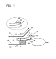
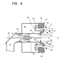
- Fig. 1 is an enlarged view of a part where guide members are disposed in a solid fuel burner illustrated in Fig. 2, and Fig. 2 is a sectional view of the solid fuel burner according to the present embodiment.
- the solid fuel burner is inserted in a burner throat 30 of a furnace wall provided with water pipes 31 and has a combustion-assisting oil gun 24 at its center axis and a fuel ejecting nozzle, i.e., a fuel nozzle 11 for ejecting a mixture fluid of a fuel and a carrier gas around the combustion-assisting oil gun 24.
- the combustion-assisting oil gun 24 passing through the fuel nozzle 11 along the center axis is used for ignition of the fuel at start-up of the solid fuel burner.
- a condenser (obstacle) 33 is disposed around the oil gun 24, and a passage contracting member (venturi) 32 is disposed upstream of the condenser 33.
- a flow of the mixture fluid 16 can be deflected along the direction indicated by arrows to increase the density of solid fuel particles inside the inner circumferential wall 29 of the fuel nozzle 11, which facilitates ignition of the solid fuel at the outlet of the fuel nozzle 11.
- the furnace wall is provided with a wind box 26 into which a combustion air is introduced, and in the wind box 26, outer air nozzles concentric with the fuel nozzle 11, i.e., a secondary air nozzle 13 and a tertiary air nozzle 14 are provided for ejecting air.
- the tertiary air nozzle 14 is provided with a swirler 28 for swirling air.
- a flow is induced at the burner outlet, between the fuel jet from the fuel nozzle 11, i.e., the flow of the mixture fluid of the fuel and its carrier gas 16 and the combustion air flows such as a secondary air flow 17 ejected from the secondary air nozzle 13 and a tertiary air flow 18 ejected from the tertiary air nozzle 14, in the direction reverse to the flow of the mixture fluid 16 and the tertiary air flow 18.
- the circulating flow 19 comprises a circulating flow 19a formed downstream of a flame stabilizer 23 and a circulating flow 19b formed downstream of a first guide member 34.
- a hot gas generated by combustion of the fuel flows into these two circulating flows 19a, 19b from a downstream zone in the furnace 41 and stays there. The ignition occurs such that the hot gas is mixed with the fuel particles in the flow of the mixture fluid 16 at the outlet of the solid fuel burner and then the temperature of the fuel particles is raised by radiant heat from the furnace 41.
- a guide sleeve 25 for ejecting the tertiary air toward the outside of the solid fuel jet is provided at the end part (furnace-side outlet part) of an inner circumferential wall 38 of the tertiary air nozzle 14.
- the flame stabilizer 23 composed of a flame stabilizing base member 23a and a flame stabilizing sleeve 23b is provided for radially outwardly narrowing and converging the flow of the mixture fluid 16 ejected from the fuel nozzle 11, which is composed of the solid fuel and its carrier gas, and the secondary air flow 17 ejected from the secondary nozzle 13, and the two guide members 34, 35 are provided for ejecting the secondary air flow 17 into the furnace 41 outwardly beyond the tertiary air flow 18.
- the first guide member 34 and the second guide member 35 are provided at a distance from each other in the flow direction of the combustion air.
- the first guide member 34 is located at the end of the flame stabilizing sleeve 23b and disposed such that the jet angle of the secondary air flow 17, which is deflected by the first guide member 34 and then ejected into the furnace 41, with respect to the burner center axis is larger than the jet angle of the tertiary air flow 18 with respect to the burner center axis.
- the secondary air flow 17 and the tertiary air flow 18 intersect each other at the burner outlet, which facilitates formation of the circulating flows 19a, 19b.
- the second guide member 35 is placed in the same direction as the first guide member 34 with respect to the burner center axis, but upstream of the first guide member 34 in the burner. In addition, a gap is formed between the second guide member 35 and the flame stabilizing sleeve 23b.
- the distance between the first guide member 34 and the second guide member 35 is equal to the distance between the second guide member 35 and the flame stabilizer 23.
- the secondary air flow 17 comprises a secondary air jet 17a ejected into the furnace 41 through the gap between the guide sleeve 25 and the second guide member 35 and a secondary air jet 17b ejected into the furnace 41 through the gap between the second guide member 35 and the first guide member 34, and the secondary air jets 17a, 17b are ejected outwardly with respect to the burner center axis beyond the tertiary air flow 18.
- a fin member 36 connects to the second guide member 35, and the fin member 36 is attached in an upright position to the outer circumferential wall of the flame stabilizer 23 along the gas flow direction.
- a plurality of the fin members 36 are arranged at a pitch of 30 to 50 mm uniformly in the circumferential direction of the flame stabilizer 23 and radially. With the plurality of fin members 36 arranged at small intervals, the secondary air jets 17a, 17b can be rectified.
- the second guide member 35 is provided at the end of the fin member 36, moreover, the secondary air jet 17a rectified with the fin members 36 can be ejected into the furnace 41 along the second guide member 35 perpendicularly outwardly with respect to the burner center axis. With this flow, the flame stabilizer 23 and the second guide member 35 can be cooled to prevent the burning of the burner due to radiant heat from the furnace 41.
- the secondary air jet 17b rectified with the fin members 36, which is a part of the secondary air flow 17, can be ejected along the flame stabilizing sleeve 23b.
- the secondary air jet 17b rectified with the fin members 36 can be ejected along the first guide member 34 perpendicularly with respect to the burner center axis.
- This jet 17b flows the gap between the first guide member 34 and the second guide member 35, so that a flow is formed along the surface of the second guide member 35 directed toward the furnace 41.
- the relatively small circulating flow 19b formed downstream of the second guide member 35 may draw in a hot gas from the furnace. This may cause the burning of the second guide member 35 or the deposition of ash on the second guide member 35, but the deposition of ash on the second guide member 35 can be prevented by the secondary air jet 17b coming out of the gap between the first and the second guide members 34, 35.
- the secondary air jet 17b can be ejected perpendicularly with respect to the burner center axis to prevent the deposition of ash on the surface of the second guide member 35.
- Fig. 3 shows the secondary air jets 17a, 17b and the circulating flows 19a, 19b in a case where the first guide member 34 and the second guide member 35 have almost the same outer diameter.
- the second guide member 35 can be cooled by the secondary air jet 17b flowing through the gap between the first guide member 34 and the second guide member 35.
- the small circulating flow 19b formed downstream of the second guide member 35 may cause the burning of the second guide member 35 or the deposition of ash on it.
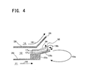
- Fig. 4 shows the secondary air jets 17a, 17b in a case where the first guide member 34 does not exist virtually.
- the first guide member 34 When the first guide member 34 does not exist, the secondary air flow 17b being a part of the secondary air flow 17 jets out along the burner center axis. Therefore, the cooling air does not flow along the front side (furnace side) of the second guide member 35, and the small circulating flow 19b due to the second guide member 35 is formed on the surface side of the second guide member 35. In this case, the ash-containing hot gas in the furnace 41 may be brought into contact with the surface of the second guide member 35 to cause the burning or the deposition of ash. Therefore, the first guide member 34 is effective in preventing the deposition of ash or the burning when it is shorter than the second guide member 35.
- the present embodiment in which the second guide member 35 is provided at the end of the fin member 36, has an effect significantly different from the effect of the fin member according to the above-mentioned publication. Since the gap is formed between the second guide member 35 provided at the end of the fin member 36 and the flame stabilizing sleeve 23b, the secondary air flow 17 can be separated into the jet 17a flowing along the inner side of the second guide member 35 and the jet 17b flowing through the gap between the second guide member 35 and the flame stabilizing sleeve 23b.
- the jet 17a can cool the second guide member 35 from the inner side, while the jet 17b can prevent the deposition of ash on the surface of the second guide member 35 because it flows toward the tertiary air nozzle 14 along the second guide member 35 owing to the first guide member 34.
- the secondary air jet 17b not only prevents the burning of the flame stabilizer 23 and the second guide member 35 by cooling but also prevents the deposition of ash on the flame stabilizer 23 and the second guide member 35, improving the solid fuel ignition and flaming stability more than before.
- the two guide members are provided because when the major second guide member 35 is provided on the fin member 36, the temperature around these two guide members 34, 35 can be lowered by 250°C as compared with the case where a single guide member is provided, which prevents the burning of the first and the second guide members 34, 35.
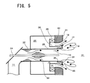
- Fig. 5 shows a sectional view showing the structure of a solid fuel burner according to Embodiment 2 of the present invention
- Fig. 6 shows an enlarged view of its major part.
- the present embodiment is configured such that the part corresponding to the flame stabilizer 23 in the first embodiment is removed from the outward end of the partition between the fuel nozzle 11 and the secondary air nozzle 13 (the inner circumferential wall 29 of the secondary air nozzle 13).
- the first guide member 34 for guiding the secondary air flow 17 outwardly from the burner center axis is provided at the outward end of the inner circumferential wall 29 of the secondary air gas nozzle 13, a plurality of the fin members 36 to be cooled by the secondary air flow 17 are attached to the outside of the inner circumferential wall 29 of the secondary air nozzle 13, and moreover, the second guide member 35 for guiding the secondary air flow 17 outwardly from the burner center axis is provided at the end of the fin member 36 at a distance from the first guide member 34, upstream of the secondary air flow 17 from the first guide member 34.
- the gap for permitting passage of a part of the secondary air flow 17 is formed between the inner circumferential wall 29 of the secondary air nozzle 13, which extends to the first guide member 34, and the second guide member 35 so as to separate the secondary air flow 17 into the furnace front side flow (the jet 17b) and the rear side flow (the jet 17a) at the second guide member 35.
- the relatively small circulating flow 19b can be formed downstream of the second guide member 35 and may draw in a hot gas from the furnace. This may cause the burning of the second guide member 35 or the deposition of ash on the second guide member 35, but the deposition of ash and the like on the second guide member 35 can be prevented by the secondary air jet 17b coming out of the gap between the first and the second guide members 34, 35.
- the secondary air jet 17b can be ejected perpendicularly with respect to the burner center axis to prevent the deposition of ash on the surface of the second guide member 35.
- the outward angles of the first guide member 34 and the second guide member 35 with respect to the burner center axis are larger than the outward angle of the guide sleeve 25 with respect to the burner center axis, the secondary air flow 17 and the tertiary air flow 18 intersect each other at the burner outlet, which facilitates formation of the circulating flow 19b.
- the fin member 36 terminates at the rear side of the second guide member 35 (the boiler's interior side is called as the front side) in the illustrated example, it may extend to the rear side of the first guide member 34, for example, without being limited to the height in the radial direction of the burner, the length in the axial direction or the shape shown in the burner's side view of Fig. 1 , etc.
- the fin member 36 is acceptable as long as it is cooled by the secondary air flow 17, it retains the second guide member 35 and the gap is formed between the second guide member 35 and the inner circumferential wall 29 of the secondary air nozzle, which extends continuously from the fuel nozzle 11 to the first guide member 34, so as to separate the secondary air flow 17 into the front side flow and the rear side flow with the second guide member 35.
- the solid fuel burner has been described with reference to a burner in which pulverized coal prepared by pulverizing coal is employed as the fuel and air is employed as the combustion gas, the present invention should not be construed as limited by the type of fuel or the composition of the combustion gas.
- solid fuel all the solid fuels such as brown coal or various biomasses can be employed in addition to the coal, while as the combustion gas, a recirculated exhaust gas, a mixed gas of air or oxygen and exhaust gas or the like can be employed.
- first guide member 34, the second guide member 35, the fin member 36 and the fuel nozzle 11 have been described as independent members for the convenience of description, even when a few of them or all of them are produced by casting or the like into an integral continuous member, they fall within the scope of the present invention.
Landscapes
- Engineering & Computer Science (AREA)
- Chemical & Material Sciences (AREA)
- Combustion & Propulsion (AREA)
- Mechanical Engineering (AREA)
- General Engineering & Computer Science (AREA)
- Physics & Mathematics (AREA)
- Thermal Sciences (AREA)
- Gas Burners (AREA)
Applications Claiming Priority (2)
| Application Number | Priority Date | Filing Date | Title |
|---|---|---|---|
| JP2011166366A JP5794419B2 (ja) | 2011-07-29 | 2011-07-29 | 固体燃料バーナ |
| PCT/JP2012/004764 WO2013018328A1 (ja) | 2011-07-29 | 2012-07-26 | 固体燃料バーナ |
Publications (3)
| Publication Number | Publication Date |
|---|---|
| EP2738461A1 EP2738461A1 (en) | 2014-06-04 |
| EP2738461A4 EP2738461A4 (en) | 2015-04-15 |
| EP2738461B1 true EP2738461B1 (en) | 2016-09-14 |
Family
ID=47628879
Family Applications (1)
| Application Number | Title | Priority Date | Filing Date |
|---|---|---|---|
| EP12820064.9A Active EP2738461B1 (en) | 2011-07-29 | 2012-07-26 | Solid fuel burner |
Country Status (7)
| Country | Link |
|---|---|
| EP (1) | EP2738461B1 (ko) |
| JP (1) | JP5794419B2 (ko) |
| KR (1) | KR101560076B1 (ko) |
| AU (1) | AU2012291497B2 (ko) |
| MY (1) | MY155735A (ko) |
| PL (1) | PL2738461T3 (ko) |
| WO (1) | WO2013018328A1 (ko) |
Families Citing this family (8)
| Publication number | Priority date | Publication date | Assignee | Title |
|---|---|---|---|---|
| JP6301650B2 (ja) * | 2013-12-27 | 2018-03-28 | 川崎重工業株式会社 | 石油ピッチ燃料用バーナおよびその使用方法 |
| JP6304872B2 (ja) * | 2014-02-12 | 2018-04-04 | 三菱日立パワーシステムズ株式会社 | バーナ、およびそれを用いたボイラ、バーナの燃焼方法 |
| JP6326593B2 (ja) * | 2014-02-14 | 2018-05-23 | 三菱日立パワーシステムズ株式会社 | バーナ装置、およびそれを用いたボイラ、バーナ装置の燃焼方法 |
| JP6797714B2 (ja) * | 2017-02-22 | 2020-12-09 | 三菱パワー株式会社 | 燃焼装置 |
| CA3086988C (en) | 2017-12-26 | 2022-07-26 | Mitsubishi Hitachi Power Systems, Ltd. | Solid fuel burner and flame stabilizer for solid fuel burner |
| JP6615252B2 (ja) * | 2018-03-01 | 2019-12-04 | 川崎重工業株式会社 | 石油ピッチ燃料用バーナおよびその使用方法 |
| JP6813533B2 (ja) | 2018-05-22 | 2021-01-13 | 三菱パワー株式会社 | バーナおよび燃焼装置 |
| IT201900020508A1 (it) * | 2019-11-06 | 2021-05-06 | Ac Boilers S P A | Gruppo bruciatore, metodo per operare detto gruppo bruciatore e impianto comprendente detto gruppo bruciatore |
Family Cites Families (15)
| Publication number | Priority date | Publication date | Assignee | Title |
|---|---|---|---|---|
| JPS6172906A (ja) * | 1984-09-17 | 1986-04-15 | Babcock Hitachi Kk | 冷却型低NOxバ−ナ装置 |
| JPS6280409A (ja) * | 1985-10-04 | 1987-04-13 | Babcock Hitachi Kk | 固体燃料の低NOx燃焼装置 |
| JPS6370009A (ja) * | 1986-09-09 | 1988-03-30 | Babcock Hitachi Kk | 微粉炭焚燃焼装置 |
| JP2638040B2 (ja) * | 1988-02-23 | 1997-08-06 | バブコツク日立株式会社 | 微粉炭燃焼装置 |
| JPH04292702A (ja) * | 1991-03-20 | 1992-10-16 | Babcock Hitachi Kk | 微粉炭燃焼装置 |
| JPH06172906A (ja) * | 1992-12-08 | 1994-06-21 | Furukawa Alum Co Ltd | 耐落下衝撃性に優れたアルミニウム合金板およびその製造方法 |
| JPH06272817A (ja) * | 1993-03-24 | 1994-09-27 | Babcock Hitachi Kk | 微粉炭燃焼装置 |
| JP3344694B2 (ja) * | 1997-07-24 | 2002-11-11 | 株式会社日立製作所 | 微粉炭燃焼バーナ |
| JPH11148611A (ja) * | 1997-11-19 | 1999-06-02 | Babcock Hitachi Kk | 燃焼装置 |
| JPH11304116A (ja) * | 1998-04-17 | 1999-11-05 | Babcock Hitachi Kk | 固体燃料燃焼バーナとその燃焼方法 |
| JP2001336707A (ja) * | 2000-05-25 | 2001-12-07 | Hitachi Ltd | 微粉炭燃焼バーナ |
| JP3970139B2 (ja) * | 2002-09-10 | 2007-09-05 | 三菱重工業株式会社 | 燃焼器 |
| GB0403057D0 (en) * | 2004-02-12 | 2004-03-17 | Rolls Royce Plc | Guide member for a fuel injection arrangement |
| US20060029895A1 (en) * | 2004-03-08 | 2006-02-09 | Joel Vatsky | Fuel injector for low NOx and enhanced flame stabilization |
| JP4261401B2 (ja) * | 2004-03-24 | 2009-04-30 | 株式会社日立製作所 | バーナと燃料燃焼方法及びボイラの改造方法 |
-
2011
- 2011-07-29 JP JP2011166366A patent/JP5794419B2/ja active Active
-
2012
- 2012-07-26 AU AU2012291497A patent/AU2012291497B2/en active Active
- 2012-07-26 KR KR1020137033617A patent/KR101560076B1/ko active IP Right Grant
- 2012-07-26 PL PL12820064T patent/PL2738461T3/pl unknown
- 2012-07-26 EP EP12820064.9A patent/EP2738461B1/en active Active
- 2012-07-26 WO PCT/JP2012/004764 patent/WO2013018328A1/ja active Application Filing
- 2012-07-26 MY MYPI2013004068A patent/MY155735A/en unknown
Also Published As
| Publication number | Publication date |
|---|---|
| JP2013029270A (ja) | 2013-02-07 |
| EP2738461A1 (en) | 2014-06-04 |
| KR20140051858A (ko) | 2014-05-02 |
| JP5794419B2 (ja) | 2015-10-14 |
| AU2012291497A1 (en) | 2013-11-21 |
| WO2013018328A1 (ja) | 2013-02-07 |
| PL2738461T3 (pl) | 2017-02-28 |
| KR101560076B1 (ko) | 2015-10-13 |
| EP2738461A4 (en) | 2015-04-15 |
| MY155735A (en) | 2015-11-17 |
| AU2012291497B2 (en) | 2015-04-09 |
Similar Documents
| Publication | Publication Date | Title |
|---|---|---|
| EP2738461B1 (en) | Solid fuel burner | |
| US6752620B2 (en) | Large scale vortex devices for improved burner operation | |
| EP1351017B1 (en) | Pulverized coal burner | |
| JP5188238B2 (ja) | 燃焼装置及びバーナの燃焼方法 | |
| US6189464B1 (en) | Pulverized coal combustion burner and combustion method thereby | |
| JPH01305206A (ja) | バーナー | |
| JPS63210508A (ja) | 超低NOx燃焼装置 | |
| US20070026356A1 (en) | Burner and combustion method for solid fuels | |
| JP5386230B2 (ja) | 燃料バーナ及び旋回燃焼ボイラ | |
| CN110186044A (zh) | 燃气-空气部分预混燃烧器 | |
| JP3643461B2 (ja) | 微粉炭燃焼バーナおよびその燃焼方法 | |
| JP5797238B2 (ja) | 燃料バーナ及び旋回燃焼ボイラ | |
| JP6871422B2 (ja) | 固体燃料バーナおよび固体燃料バーナ用保炎器 | |
| JP2010270990A (ja) | 燃料バーナ及び旋回燃焼ボイラ | |
| JPS59210205A (ja) | 微粉炭バ−ナ装置 | |
| JP2003343817A (ja) | 旋回型低NOx燃焼器 | |
| JP6640591B2 (ja) | 燃焼バーナ及び燃焼装置並びにボイラ | |
| JPS62288406A (ja) | 微粉炭バ−ナ | |
| JP4857025B2 (ja) | 多管式貫流ボイラ | |
| CN110594761A (zh) | 低温甲醇洗焚烧炉燃烧器 | |
| JPS6237606A (ja) | 固体燃料の低NOx燃焼装置 |
Legal Events
| Date | Code | Title | Description |
|---|---|---|---|
| PUAI | Public reference made under article 153(3) epc to a published international application that has entered the european phase |
Free format text: ORIGINAL CODE: 0009012 |
|
| 17P | Request for examination filed |
Effective date: 20131126 |
|
| AK | Designated contracting states |
Kind code of ref document: A1 Designated state(s): AL AT BE BG CH CY CZ DE DK EE ES FI FR GB GR HR HU IE IS IT LI LT LU LV MC MK MT NL NO PL PT RO RS SE SI SK SM TR |
|
| DAX | Request for extension of the european patent (deleted) | ||
| RAP1 | Party data changed (applicant data changed or rights of an application transferred) |
Owner name: MITSUBISHI HITACHI POWER SYSTEMS, LTD. |
|
| RA4 | Supplementary search report drawn up and despatched (corrected) |
Effective date: 20150313 |
|
| RAP1 | Party data changed (applicant data changed or rights of an application transferred) |
Owner name: MITSUBISHI HITACHI POWER SYSTEMS, LTD. |
|
| RIC1 | Information provided on ipc code assigned before grant |
Ipc: F23D 14/78 20060101ALI20150309BHEP Ipc: F23D 1/00 20060101AFI20150309BHEP |
|
| GRAP | Despatch of communication of intention to grant a patent |
Free format text: ORIGINAL CODE: EPIDOSNIGR1 |
|
| INTG | Intention to grant announced |
Effective date: 20160202 |
|
| GRAS | Grant fee paid |
Free format text: ORIGINAL CODE: EPIDOSNIGR3 |
|
| GRAA | (expected) grant |
Free format text: ORIGINAL CODE: 0009210 |
|
| AK | Designated contracting states |
Kind code of ref document: B1 Designated state(s): AL AT BE BG CH CY CZ DE DK EE ES FI FR GB GR HR HU IE IS IT LI LT LU LV MC MK MT NL NO PL PT RO RS SE SI SK SM TR |
|
| REG | Reference to a national code |
Ref country code: GB Ref legal event code: FG4D |
|
| REG | Reference to a national code |
Ref country code: CH Ref legal event code: EP |
|
| REG | Reference to a national code |
Ref country code: IE Ref legal event code: FG4D |
|
| REG | Reference to a national code |
Ref country code: AT Ref legal event code: REF Ref document number: 829427 Country of ref document: AT Kind code of ref document: T Effective date: 20161015 |
|
| REG | Reference to a national code |
Ref country code: DE Ref legal event code: R096 Ref document number: 602012023089 Country of ref document: DE |
|
| REG | Reference to a national code |
Ref country code: NL Ref legal event code: FP |
|
| REG | Reference to a national code |
Ref country code: LT Ref legal event code: MG4D |
|
| PG25 | Lapsed in a contracting state [announced via postgrant information from national office to epo] |
Ref country code: LT Free format text: LAPSE BECAUSE OF FAILURE TO SUBMIT A TRANSLATION OF THE DESCRIPTION OR TO PAY THE FEE WITHIN THE PRESCRIBED TIME-LIMIT Effective date: 20160914 Ref country code: HR Free format text: LAPSE BECAUSE OF FAILURE TO SUBMIT A TRANSLATION OF THE DESCRIPTION OR TO PAY THE FEE WITHIN THE PRESCRIBED TIME-LIMIT Effective date: 20160914 Ref country code: RS Free format text: LAPSE BECAUSE OF FAILURE TO SUBMIT A TRANSLATION OF THE DESCRIPTION OR TO PAY THE FEE WITHIN THE PRESCRIBED TIME-LIMIT Effective date: 20160914 Ref country code: NO Free format text: LAPSE BECAUSE OF FAILURE TO SUBMIT A TRANSLATION OF THE DESCRIPTION OR TO PAY THE FEE WITHIN THE PRESCRIBED TIME-LIMIT Effective date: 20161214 |
|
| REG | Reference to a national code |
Ref country code: AT Ref legal event code: MK05 Ref document number: 829427 Country of ref document: AT Kind code of ref document: T Effective date: 20160914 |
|
| PG25 | Lapsed in a contracting state [announced via postgrant information from national office to epo] |
Ref country code: SE Free format text: LAPSE BECAUSE OF FAILURE TO SUBMIT A TRANSLATION OF THE DESCRIPTION OR TO PAY THE FEE WITHIN THE PRESCRIBED TIME-LIMIT Effective date: 20160914 Ref country code: LV Free format text: LAPSE BECAUSE OF FAILURE TO SUBMIT A TRANSLATION OF THE DESCRIPTION OR TO PAY THE FEE WITHIN THE PRESCRIBED TIME-LIMIT Effective date: 20160914 Ref country code: GR Free format text: LAPSE BECAUSE OF FAILURE TO SUBMIT A TRANSLATION OF THE DESCRIPTION OR TO PAY THE FEE WITHIN THE PRESCRIBED TIME-LIMIT Effective date: 20161215 |
|
| PG25 | Lapsed in a contracting state [announced via postgrant information from national office to epo] |
Ref country code: EE Free format text: LAPSE BECAUSE OF FAILURE TO SUBMIT A TRANSLATION OF THE DESCRIPTION OR TO PAY THE FEE WITHIN THE PRESCRIBED TIME-LIMIT Effective date: 20160914 Ref country code: RO Free format text: LAPSE BECAUSE OF FAILURE TO SUBMIT A TRANSLATION OF THE DESCRIPTION OR TO PAY THE FEE WITHIN THE PRESCRIBED TIME-LIMIT Effective date: 20160914 |
|
| PG25 | Lapsed in a contracting state [announced via postgrant information from national office to epo] |
Ref country code: SK Free format text: LAPSE BECAUSE OF FAILURE TO SUBMIT A TRANSLATION OF THE DESCRIPTION OR TO PAY THE FEE WITHIN THE PRESCRIBED TIME-LIMIT Effective date: 20160914 Ref country code: PT Free format text: LAPSE BECAUSE OF FAILURE TO SUBMIT A TRANSLATION OF THE DESCRIPTION OR TO PAY THE FEE WITHIN THE PRESCRIBED TIME-LIMIT Effective date: 20170116 Ref country code: ES Free format text: LAPSE BECAUSE OF FAILURE TO SUBMIT A TRANSLATION OF THE DESCRIPTION OR TO PAY THE FEE WITHIN THE PRESCRIBED TIME-LIMIT Effective date: 20160914 Ref country code: BE Free format text: LAPSE BECAUSE OF FAILURE TO SUBMIT A TRANSLATION OF THE DESCRIPTION OR TO PAY THE FEE WITHIN THE PRESCRIBED TIME-LIMIT Effective date: 20160914 Ref country code: SM Free format text: LAPSE BECAUSE OF FAILURE TO SUBMIT A TRANSLATION OF THE DESCRIPTION OR TO PAY THE FEE WITHIN THE PRESCRIBED TIME-LIMIT Effective date: 20160914 Ref country code: AT Free format text: LAPSE BECAUSE OF FAILURE TO SUBMIT A TRANSLATION OF THE DESCRIPTION OR TO PAY THE FEE WITHIN THE PRESCRIBED TIME-LIMIT Effective date: 20160914 Ref country code: IS Free format text: LAPSE BECAUSE OF FAILURE TO SUBMIT A TRANSLATION OF THE DESCRIPTION OR TO PAY THE FEE WITHIN THE PRESCRIBED TIME-LIMIT Effective date: 20170114 Ref country code: BG Free format text: LAPSE BECAUSE OF FAILURE TO SUBMIT A TRANSLATION OF THE DESCRIPTION OR TO PAY THE FEE WITHIN THE PRESCRIBED TIME-LIMIT Effective date: 20161214 Ref country code: CZ Free format text: LAPSE BECAUSE OF FAILURE TO SUBMIT A TRANSLATION OF THE DESCRIPTION OR TO PAY THE FEE WITHIN THE PRESCRIBED TIME-LIMIT Effective date: 20160914 |
|
| REG | Reference to a national code |
Ref country code: DE Ref legal event code: R097 Ref document number: 602012023089 Country of ref document: DE |
|
| PLBE | No opposition filed within time limit |
Free format text: ORIGINAL CODE: 0009261 |
|
| STAA | Information on the status of an ep patent application or granted ep patent |
Free format text: STATUS: NO OPPOSITION FILED WITHIN TIME LIMIT |
|
| PG25 | Lapsed in a contracting state [announced via postgrant information from national office to epo] |
Ref country code: DK Free format text: LAPSE BECAUSE OF FAILURE TO SUBMIT A TRANSLATION OF THE DESCRIPTION OR TO PAY THE FEE WITHIN THE PRESCRIBED TIME-LIMIT Effective date: 20160914 |
|
| 26N | No opposition filed |
Effective date: 20170615 |
|
| PG25 | Lapsed in a contracting state [announced via postgrant information from national office to epo] |
Ref country code: SI Free format text: LAPSE BECAUSE OF FAILURE TO SUBMIT A TRANSLATION OF THE DESCRIPTION OR TO PAY THE FEE WITHIN THE PRESCRIBED TIME-LIMIT Effective date: 20160914 |
|
| REG | Reference to a national code |
Ref country code: DE Ref legal event code: R119 Ref document number: 602012023089 Country of ref document: DE |
|
| REG | Reference to a national code |
Ref country code: CH Ref legal event code: PL |
|
| GBPC | Gb: european patent ceased through non-payment of renewal fee |
Effective date: 20170726 |
|
| REG | Reference to a national code |
Ref country code: IE Ref legal event code: MM4A |
|
| REG | Reference to a national code |
Ref country code: FR Ref legal event code: ST Effective date: 20180330 |
|
| PG25 | Lapsed in a contracting state [announced via postgrant information from national office to epo] |
Ref country code: LI Free format text: LAPSE BECAUSE OF NON-PAYMENT OF DUE FEES Effective date: 20170731 Ref country code: CH Free format text: LAPSE BECAUSE OF NON-PAYMENT OF DUE FEES Effective date: 20170731 Ref country code: DE Free format text: LAPSE BECAUSE OF NON-PAYMENT OF DUE FEES Effective date: 20180201 Ref country code: IE Free format text: LAPSE BECAUSE OF NON-PAYMENT OF DUE FEES Effective date: 20170726 Ref country code: GB Free format text: LAPSE BECAUSE OF NON-PAYMENT OF DUE FEES Effective date: 20170726 |
|
| PG25 | Lapsed in a contracting state [announced via postgrant information from national office to epo] |
Ref country code: FR Free format text: LAPSE BECAUSE OF NON-PAYMENT OF DUE FEES Effective date: 20170731 |
|
| PG25 | Lapsed in a contracting state [announced via postgrant information from national office to epo] |
Ref country code: LU Free format text: LAPSE BECAUSE OF NON-PAYMENT OF DUE FEES Effective date: 20170726 |
|
| PG25 | Lapsed in a contracting state [announced via postgrant information from national office to epo] |
Ref country code: MT Free format text: LAPSE BECAUSE OF NON-PAYMENT OF DUE FEES Effective date: 20170726 |
|
| PG25 | Lapsed in a contracting state [announced via postgrant information from national office to epo] |
Ref country code: AL Free format text: LAPSE BECAUSE OF FAILURE TO SUBMIT A TRANSLATION OF THE DESCRIPTION OR TO PAY THE FEE WITHIN THE PRESCRIBED TIME-LIMIT Effective date: 20160914 |
|
| PG25 | Lapsed in a contracting state [announced via postgrant information from national office to epo] |
Ref country code: MC Free format text: LAPSE BECAUSE OF FAILURE TO SUBMIT A TRANSLATION OF THE DESCRIPTION OR TO PAY THE FEE WITHIN THE PRESCRIBED TIME-LIMIT Effective date: 20160914 Ref country code: HU Free format text: LAPSE BECAUSE OF FAILURE TO SUBMIT A TRANSLATION OF THE DESCRIPTION OR TO PAY THE FEE WITHIN THE PRESCRIBED TIME-LIMIT; INVALID AB INITIO Effective date: 20120726 |
|
| PG25 | Lapsed in a contracting state [announced via postgrant information from national office to epo] |
Ref country code: CY Free format text: LAPSE BECAUSE OF NON-PAYMENT OF DUE FEES Effective date: 20160914 |
|
| PG25 | Lapsed in a contracting state [announced via postgrant information from national office to epo] |
Ref country code: MK Free format text: LAPSE BECAUSE OF FAILURE TO SUBMIT A TRANSLATION OF THE DESCRIPTION OR TO PAY THE FEE WITHIN THE PRESCRIBED TIME-LIMIT Effective date: 20160914 |
|
| PG25 | Lapsed in a contracting state [announced via postgrant information from national office to epo] |
Ref country code: TR Free format text: LAPSE BECAUSE OF FAILURE TO SUBMIT A TRANSLATION OF THE DESCRIPTION OR TO PAY THE FEE WITHIN THE PRESCRIBED TIME-LIMIT Effective date: 20160914 |
|
| REG | Reference to a national code |
Ref country code: NL Ref legal event code: HC Owner name: MITSUBISHI POWER, LTD.; JP Free format text: DETAILS ASSIGNMENT: CHANGE OF OWNER(S), CHANGE OF OWNER(S) NAME; FORMER OWNER NAME: MITSUBISHI HITACHI POWER SYSTEMS, LTD. Effective date: 20210114 |
|
| REG | Reference to a national code |
Ref country code: FI Ref legal event code: PCE Owner name: MITSUBISHI POWER, LTD. |
|
| PGFP | Annual fee paid to national office [announced via postgrant information from national office to epo] |
Ref country code: NL Payment date: 20230614 Year of fee payment: 12 Ref country code: IT Payment date: 20230612 Year of fee payment: 12 |
|
| PGFP | Annual fee paid to national office [announced via postgrant information from national office to epo] |
Ref country code: PL Payment date: 20230614 Year of fee payment: 12 |
|
| PGFP | Annual fee paid to national office [announced via postgrant information from national office to epo] |
Ref country code: FI Payment date: 20230712 Year of fee payment: 12 |