EP2738143B1 - Precision forming of sheet glass and sheet rolling apparatus - Google Patents
Precision forming of sheet glass and sheet rolling apparatus Download PDFInfo
- Publication number
- EP2738143B1 EP2738143B1 EP12306484.2A EP12306484A EP2738143B1 EP 2738143 B1 EP2738143 B1 EP 2738143B1 EP 12306484 A EP12306484 A EP 12306484A EP 2738143 B1 EP2738143 B1 EP 2738143B1
- Authority
- EP
- European Patent Office
- Prior art keywords
- rollers
- pair
- spacer belts
- spacer
- belts
- Prior art date
- Legal status (The legal status is an assumption and is not a legal conclusion. Google has not performed a legal analysis and makes no representation as to the accuracy of the status listed.)
- Not-in-force
Links
- 239000005357 flat glass Substances 0.000 title claims description 33
- 238000005096 rolling process Methods 0.000 title description 47
- 125000006850 spacer group Chemical group 0.000 claims description 128
- 239000012768 molten material Substances 0.000 claims description 29
- 238000000034 method Methods 0.000 claims description 14
- 239000006060 molten glass Substances 0.000 claims description 10
- 229910045601 alloy Inorganic materials 0.000 claims description 7
- 239000000956 alloy Substances 0.000 claims description 7
- 229910052751 metal Inorganic materials 0.000 claims description 4
- 239000002184 metal Substances 0.000 claims description 4
- 239000000463 material Substances 0.000 description 34
- 230000008878 coupling Effects 0.000 description 10
- 238000010168 coupling process Methods 0.000 description 10
- 238000005859 coupling reaction Methods 0.000 description 10
- 239000011521 glass Substances 0.000 description 7
- 230000033001 locomotion Effects 0.000 description 7
- 230000007246 mechanism Effects 0.000 description 5
- 230000004048 modification Effects 0.000 description 4
- 238000012986 modification Methods 0.000 description 4
- 238000002144 chemical decomposition reaction Methods 0.000 description 3
- 239000012530 fluid Substances 0.000 description 3
- 230000008569 process Effects 0.000 description 3
- 230000008901 benefit Effects 0.000 description 2
- 238000000926 separation method Methods 0.000 description 2
- 238000004513 sizing Methods 0.000 description 2
- 229910018487 Ni—Cr Inorganic materials 0.000 description 1
- 229910000831 Steel Inorganic materials 0.000 description 1
- 238000000137 annealing Methods 0.000 description 1
- VNNRSPGTAMTISX-UHFFFAOYSA-N chromium nickel Chemical compound [Cr].[Ni] VNNRSPGTAMTISX-UHFFFAOYSA-N 0.000 description 1
- 238000010924 continuous production Methods 0.000 description 1
- 238000001816 cooling Methods 0.000 description 1
- 239000012809 cooling fluid Substances 0.000 description 1
- 239000006059 cover glass Substances 0.000 description 1
- 238000004049 embossing Methods 0.000 description 1
- 239000006112 glass ceramic composition Substances 0.000 description 1
- 230000005484 gravity Effects 0.000 description 1
- 229910001026 inconel Inorganic materials 0.000 description 1
- 238000004519 manufacturing process Methods 0.000 description 1
- 238000005259 measurement Methods 0.000 description 1
- 239000010935 stainless steel Substances 0.000 description 1
- 229910001220 stainless steel Inorganic materials 0.000 description 1
- 239000010959 steel Substances 0.000 description 1
- 230000001360 synchronised effect Effects 0.000 description 1
Images


Classifications
-
- C—CHEMISTRY; METALLURGY
- C03—GLASS; MINERAL OR SLAG WOOL
- C03B—MANUFACTURE, SHAPING, OR SUPPLEMENTARY PROCESSES
- C03B13/00—Rolling molten glass, i.e. where the molten glass is shaped by rolling
- C03B13/16—Construction of the glass rollers
-
- C—CHEMISTRY; METALLURGY
- C03—GLASS; MINERAL OR SLAG WOOL
- C03B—MANUFACTURE, SHAPING, OR SUPPLEMENTARY PROCESSES
- C03B13/00—Rolling molten glass, i.e. where the molten glass is shaped by rolling
- C03B13/04—Rolling non-patterned sheets continuously
-
- C—CHEMISTRY; METALLURGY
- C03—GLASS; MINERAL OR SLAG WOOL
- C03B—MANUFACTURE, SHAPING, OR SUPPLEMENTARY PROCESSES
- C03B17/00—Forming molten glass by flowing-out, pushing-out, extruding or drawing downwardly or laterally from forming slits or by overflowing over lips
- C03B17/06—Forming glass sheets
Definitions
- the present disclosure relates generally to forming of sheet glass by rolling. More specifically, the present disclosure relates to setting of a nip gap formed by a pair of rollers.
- nip gap Passing a stream or ribbon of molten glass through a nip gap formed by a pair of rollers is one of the oldest methods of producing sheet glass.
- the thickness of the rolled sheet glass is determined by the nip gap, which means that any variations in the width of the nip gap as the rollers rotate will be transferred to the thickness of the rolled sheet glass.
- collars mounted in recesses in the rollers are used to set the nip gap between the rollers. The collars on one roller are pressed against the collars on the other roller to set the nip gap. Variability of the nip gap is influenced by the dimensional accuracy of the rollers, collars, and recesses in which the collars are mounted.
- Rolling is really an old method of producing sheet glass. Numerous embodiments of rolling apparatus are disclosed in the prior art. French patent FR 715 635 discloses a rolling apparatus comprising three rollers: a lower roller and two upper rollers. Said lower roller and one of said upper rollers may bear end rings.
- US patent 3 486 879 discloses an apparatus, for forming a length of thin ribbon from a vitreous material, comprising a pair of driven cylindrical rollers disposed parallel and in substantially continuous rolling contact with each other, defining therebetween an elongated orifice having closed end portions, the central portion of said orifice being deeper than said end portions; said orifice being formed by a circumferential channel incorporated intermediate the ends of at least one roller, said channel having a bottom portion and sides, said sides terminating in cylindrical shoulder portions to provide said substantially continuous rolling contact between said rollers.
- Japanese patent application JPS63 089421 discloses an apparatus comprising an upper forming roller and a lower forming roller. Each of said rollers bears thickness adjusting rings at its ends.
- the apparatus includes a pair of rollers arranged in opposing relation to form a nip gap. At least one of the rollers is translatable to adjust a width of the nip gap.
- the apparatus includes a pair of spacer belts passing in between the pair of rollers. The pair of spacer belts is spaced apart along a length of the pair of rollers and has a thickness to set the width of the nip gap.
- the apparatus includes a belt guide disposed adjacent to at least one of the rollers. At least one of the spacer belts passes around one of the rollers and the belt guide.
- At least one actuator is coupled to at least one of the rollers and is operable to adjust the width of nip gap until the pair of spacer belts is gripped by the pair of rollers and the thickness of the pair of spacer belts sets the width of the nip gap.
- the belt guide includes a pair of pulleys, where each of the spacer belts passes around one of the rollers and one of the pulleys.
- the belt guide includes an auxiliary roller, where the pair of spacer belts passes around one of the rollers and the auxiliary roller.
- the belt guide includes a pair of guide blocks and a set of needle rollers attached to each of the guide blocks, where each of the spacer belts passes around one of the rollers and the set of needle rollers attached to one of the guide blocks.
- the set of needle rollers on each guide blocks is arranged in an arc or circular path on the guide block.
- the thickness of the pair of spacer belts is in a range from 0.1 mm to 4 mm.
- the thickness of the pair of spacer belts is 1 mm or less.
- the thickness of the pair of spacer belts is uniform.
- the thickness of the pair of spacer belts is profiled.
- the pair of spacer belts is made of a metal or an alloy.
- the apparatus further includes a pair of motors coupled to the pair of rollers for selectively rotating the rollers.
- the apparatus further includes a delivery vessel positioned to deliver molten material to the nip gap.
- the present disclosure also describes a method of forming a sheet glass.
- the method includes arranging a pair of rollers in opposing relation to form a nip gap.
- the method includes passing a pair of spacer belts between the pair of rollers.
- the passing includes spacing the pair of spacer belts apart along a length of the pair of rollers and passing at least one of the spacer belts around one of the rollers and a belt guide disposed adjacent to the one of the rollers.
- the method includes translating at least one of the pair of rollers to adjust a width of the nip gap until the pair of spacer belts is gripped by the pair of rollers and the width of the nip gap is set by a thickness of the pair of spacer belts.
- the method includes rotating at least one of the rollers.
- the method further includes delivering molten glass to the nip gap having the width set by the pair of spacer belts to form the sheet glass.
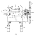
- FIG. 1 shows a sheet rolling apparatus 10 that can receive a stream or ribbon of molten material and form the molten material into a sheet material with a select thickness and width.
- the molten material is molten glass and the sheet material formed by rolling is sheet glass.
- glass is intended to cover glass or other material containing glass, such as a glass-ceramic material.
- the rolling apparatus 10 includes a pair of rollers 12a, 12b arranged in parallel and on opposite sides of a reference axis 13.
- the rollers 12a, 12b may or may not be equidistant from the reference axis 13.
- the axial axes of the rollers 12a, 12b are parallel to the reference axis 13.
- the rollers 12a, 12b have circular cross-sections and cylindrical rolling surfaces 15a, 15b, which may be smooth to form a smooth sheet glass or may incorporate embossing textures to form an embossed sheet glass.
- the rollers 12a, 12b are mounted on and rotatable with roller shafts 14a, 14b.
- the roller shaft 14a extends through bearing blocks 16a, 18a arranged near distal ends of the roller 12a and is supported for rotation by bearings in the bearing blocks 16a, 18a.
- the roller shaft 14b extends through bearing blocks 16b, 18b arranged near distal ends of the roller 12b and is supported for rotation by bearings in the bearing blocks 16b, 18b.
- the roller shafts 14a, 14b are coupled to drive motor shafts 20a, 20b of drive motors 22a, 22b by shaft couplings 24a, 24b.
- the shaft couplings 24a, 24b are offset couplings, such as Schmidt Offset Couplings, which are capable of compensating for parallel shift between the roller shafts 14a, 14b and the drive motor shafts 20a, 20b while transmitting torque and speed. With the offset couplings, it is not necessary for the drive motor shafts 20a, 20b to be axially aligned with the roller shafts 14a, 14b.
- the offset couplings will allow the drive motors 22a, 22b to be fixed to a support frame 25 while the rollers 12a, 12b can be translated relative to the support frame 25.
- the drive motor shafts 20a, 20b may be coupled to the roller shafts 14a, 14b via inline couplings.
- the positions of the drive motors 22a, 22b and rollers 12a, 12b would need to be coordinated such that the roller shafts 14a, 14b and drive motor shafts 20a, 20b are axially aligned.
- Pulleys 26, 28 are positioned adjacent to and at a distance from the roller 12a.
- the axial axes of the pulleys 26, 28 are parallel to the reference axis 13 or to the axial axis of the roller 12a.
- the pulleys 26, 28 are mounted on pulley shafts 30, 32 in a manner that allows them to rotate freely on the pulley shafts 30, 32.
- the pulley shafts 30, 32 are attached at one end to the bearing blocks 16a, 18a, which allows the relationship between the pulleys 26, 28 and the roller 12a to be maintained through any translational motion of the roller 12a.
- a pair of spacer belts 34, 36 is mounted on the roller 12a and spaced apart along the length of the roller 12a.
- the spacing between the spacer belts 34, 36 will need to be equal to or greater than the width of the sheet material to be rolled.
- the spacer belts 34, 36 will be identical in thickness but may or may not be identical in width.
- the thickness of the spacer belts 34, 36 will be determined by the thickness of the sheet material to be rolled.
- the spacer belts 34, 36 are endless belts and pass around the roller 12a and the pulleys 26, 28.
- the pulleys 26, 28 may have grooves to receive the spacer belts 34, 36.
- the spacer belts 34, 36 are also seamless.
- the spacer belts 34, 36 will typically be made of a relatively hard or stiff material such as a metal or an alloy. Unmounted, the spacer belts 34, 36 may have a circular shape or oval shape or other continuous loop shape.
- the spacer belts 34, 36 can be easily installed by passing them over the bearing block 16a and onto the roller 12a and pulleys 26, 28.
- the spacer belts 34, 36 can be temporarily deformed to a shape that would allow them to be slipped onto the pulleys 26, 28. Such temporary shape would have a span that is larger than the distance between the roller 12a and the pulleys 26, 28 so that the spacer belts 34, 36 can be pulled onto the pulleys 26, 28.
- the reverse of this process can be used to remove the spacer belts 34, 36 from the roller 12a and pulleys 26, 28.
- the spacer belts 34, 36 can be mounted on and dismounted from the roller 12a and pulleys 26, 28 without having to remove the roller 12a from the bearing blocks 16a, 18a, which is a possible advantage over collars that must engage circumferential recesses in rollers.
- the pulleys 26, 28 form a belt guide.
- another belt guide not made of pulleys may be arranged adjacent to the roller 12a, with the spacer belts 34, 36 passing over the alternate belt guide in the same manner explained for the pulleys 26, 28.
- the rollers 12a, 12b have an open position where they are not closed against the spacer belts 34, 36, as shown in FIG. 1 . In this open position, both of the rollers 12a, 12b are not in contact with both of the spacer belts 34, 36. In the particular configuration shown in FIG. 1 , only the roller 12a is in contact with the spacer belts 34, 36.
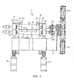
- the rollers 12a, 12b have a closed position where they are closed against the spacer belts 34, 36, as shown in FIG. 2 . In the closed position, both of the rollers 12a, 12b are in contact with the spacer belts 34, 36.
- the contact between the rollers 12a, 12b and spacer belts 34, 36 is such that the spacer belts 34, 36 are pinched or gripped between the rollers 12a, 12b.
- the rollers 12a, 12b form a nip gap 38 (see FIGS. 1 and 2 ), which is essentially a constriction.
- the width 39 of the nip gap 38 is the distance between the rollers 12a, 12b measured transverse to the axial centerlines of the rollers 12a, 12b. In the closed position, the width 39 of the nip gap 38 is determined by the thickness of the spacer belts 34, 36 in between the rollers 12a, 12b.
- the length 41 of the nip gap 38 is measured along the length of the pair of rollers 12a, 12b or along the reference axis 13.
- the length 41 of the nip gap 38 is determined by the spacing between the spacer belts 34, 36 along the length of the pair of rollers 12a, 12b or along the reference axis 13.
- the rollers 12a, 12b are moved to the closed position where the width of the nip gap 38 is set by the spacer belts 34, 36. Then, the drive motors 22a, 22b are operated to rotate the rollers 12a, 12b in opposing directions, and typically at the same speed. In alternate embodiments, only one of the drive motors may be operated to rotate its respective roller while the other roller is held fixed.
- the spacer belts 34, 36 will move around the roller 12a and pulleys 26, 28 as the rollers 12a, 12b are rotated. The motion of the spacer belts 34, 36 may result in rotation of the pulleys 36, 38 on the pulley shafts 30, 32.
- a stream or ribbon of molten material can be delivered to the nip gap 38.
- the rotating rollers 12a, 12b will pull the molten material through the nip gap 38 to form the sheet material.
- the width of the stream or ribbon of molten material delivered to the nip gap 38 is smaller than the nip gap length 41 so that contact of the molten material with the spacer belts 34, 36 can be substantially avoided.
- the width of the stream or ribbon of molten material may be the same as the nip gap length 41, which may allow contact of the molten material with the spacer belts 34, 36.
- the nip gap 38 is set by the thickness of the pair of spacer belts 34, 36 in between the rollers 12a, 12b and the spacing between the spacer belts 34, 36.
- thickness of the pair of spacer belts means the thickness of any one of the spacer belts in the pair or the representative thickness of the spacer belts in the pair when the spacer belts are arranged in a spaced-apart relation, as shown for spacer belts 34, 36 in FIGS. 1 and 2 ).
- the nip gap width 39 is determined by the thickness of the spacer belts 34, 36 between the rollers 12a, 12b.
- the precision of the nip gap 38 is a function of the straightness accuracy of the rollers 12a, 12b and the thickness accuracy of the spacer belts 34, 36.
- the roundness accuracy of the rollers 12a, 12b does not affect the precision of the nip gap 38.
- the chain of dimension that defines the nip gap 38 formed by the spacer belts 34, 36 is relatively short.
- the precision of the nip gap width is a function of the straightness accuracy and roundness accuracy of the rollers, the roundness accuracy and depth accuracy of the recesses formed in the rollers, and the roundness accuracy and thickness accuracy of the collars mounted in the recesses.
- the straightness accuracy of each roller 12a, 12b i.e., the straightness variation of each roller across a length of the roller, is within ⁇ 0.025 mm, preferably within ⁇ 0.01 mm.
- each spacer belt 34, 36 i.e., the thickness variation of each spacer belt across the width of the spacer belt, is within ⁇ 0.025 mm, preferably within ⁇ 0.01 mm, more preferably within ⁇ 0.005 mm.
- Spacer belts 34, 36 having a thickness accuracy such as described above can be sourced from standard seamless endless belt suppliers or can be machined using standard turning methods.
- Spacer belts 34, 36 and rollers 12a, 12b with thickness accuracy and straightness accuracy such as described above can be used for forming precision sheet glass by rolling.
- the rolled sheet glass is a "precision sheet glass” if the thickness accuracy of the sheet glass, i.e., the thickness variation of the sheet glass across the width of the sheet glass, is within ⁇ 0.025 mm. It should be noted that “thickness” may be uniform or non-uniform. The variation that should be within a certain amount would be relative to the desired thickness profile.
- the spacer belts 34, 36 may have a uniform thickness or may have a profiled thickness.
- a profiled thickness means that the thickness of the spacer belts 34, 36 changes along the circumference of the belts and follows a select profile.
- Spacer belts having a profiled thickness can be used to produce profiled sheet glass.
- FIG. 3A shows an example spacer belt 34a with a profiled thickness in between rollers 12a, 12b.
- FIGS. 3B and 3C show sheet thickness profiles 35a, 35b that may be formed with the spacer belt 34a.
- FIG. 4A shows an example spacer belt 34b with a profiled thickness in between rollers 12a, 12b.
- FIGS. 4B and 4C show sheet thickness profiles 35c, 35d that may be formed with the spacer belt 34b.
- the symmetrical sheet thickness profiles shown in FIGS. 3B and 4B are formed by rotating both rollers symmetrically so that the molten material flows along a fixed vertical axis.
- the asymmetrical sheet thickness profiles shown in FIGS. 3C and 4C are formed by holding one roller fixed while rotating the other roller.
- the thickness of the spacer belts 34, 36 will generally be dictated by the desired thickness of the sheet material.
- the rolling apparatus 10 is used to form sheet glass and the thickness of the spacer belts 34, 36 is in a range from 0.1 mm to 4 mm, from 0.2 mm to 3 mm, or from 0.5 mm to 1 mm.
- the width of each of the spacer belts 34, 36 need only suffice to provide a reliable gap structure between the rollers 12a, 12b.
- the width of the spacer belts 34, 36 can be in a range from 5 mm to 50 mm or from 5 mm to 40 mm. As mentioned earlier, the widths of the spacer belts 34, 36 may or may not be the same.
- the thickness and width guidelines described above may be used for uniform thickness or profiled thickness spacer belts.
- the rollers 12a, 12b in FIGS. 1 and 2 are preferably made of a material that can withstand a high temperature without physical or chemical degradation.
- the high temperature that must be withstood by the material of the rollers 12a, 12b will depend on the temperature at which the rollers 12a, 12b are maintained during a rolling process.
- molten material at temperatures from 1000 to 1500°C is delivered to the nip gap 38 while the rollers 12a, 12b are maintained at temperatures below 700°C.
- the material of the rollers 12a, 12b may be one that can withstand a high temperature of about 700°C without physical or chemical degradation.
- the rollers 12a, 12b are preferably made of a material that will not react with glass at high temperatures that would be encountered during roll forming.
- the rollers 12a, 12b may be made of stainless steel or other high temperature alloy that will not react with glass at high temperatures.
- the rollers 12a, 12b may also have internal chambers for circulating cooling fluid, e.g., to keep the rollers 12a, 12b at a lower temperature than that of the molten material delivered to the nip gap 38. Such cooling circulation may be used to reduce temperature gradients across the molten material delivered to the nip gap 38 and thereby reduce thermally-induced thickness variability of the rolled sheet material.
- the spacer belts 34, 36 are preferably made of a material that can withstand a high temperature. However, the temperature requirement of the spacer belts 34, 36 can be somewhat relaxed compared to that of the rollers 12a, 12b. This is because the spacer belts 34, 36 do not need to contact the molten material during roll forming. In some embodiments, the spacer belts 34, 36 are made of a material that can withstand temperatures up to 500°C without physical or chemical degradation. In various embodiments, the spacer belts 34, 36 are made of a hard or stiff material, typically a metal or an alloy.
- the hardness or stiffness of the material may be similar to that of the rollers 12a, 12b to avoid significant deformation of the spacer belts 34, 36 when pinched or gripped in between the rollers 12a, 12b.
- suitable materials for the spacer belts 34, 36 are steel and INCONEL ® alloys (i.e., nickel-chromium-based alloys).
- the pulleys 26, 28 may be made of the same material as the spacer belts 34, 36. In some cases, the pulleys 26, 28 may be made of a material that is not necessarily as hard as the material of the spacer belts 34, 36. In other cases, it is not necessary for the pulleys 26, 28 to withstand as high a temperature as either of the spacer belts 34, 36 or the rollers 12a, 12b.
- Any suitable actuator system can be used to move the rollers 12a, 12b between the open and closed positions. In the closed position, the actuator system can push the rollers 12a, 12b against the spacer belts 34, 36 such that the spacer belts 34, 36 are pinched or gripped in between the rollers 12a, 12b, and thereby set the width of the nip gap 38.
- the actuator system may incorporate linear, rotary, or a combination of linear and rotary actuators.
- FIG. 1 shows an actuator 42a coupled to the bearing blocks 16a, 16b.
- the manner of coupling the actuator 42a is such that the actuator 42a is operable to create opposed motions of the bearing blocks 16a, 16b that will move the rollers 12a, 12b between the open and closed positions.
- An actuator 42b coupled to the bearing blocks 18a, 18b is also shown in FIG. 1 .
- the manner of coupling the actuator 42b is such that the actuator 42b is operable to create opposed motions of the bearing blocks 18a, 18b.
- the two actuators 42a, 42b will allow balanced or symmetric motion of the rollers 12a, 12b between the open and closed positions.
- the actuators 42a, 42b are linear actuators.
- the actuators 42a, 42b are fluid powered cylinders, such as pneumatic cylinders.
- a body member 44a of the actuator 42a is coupled to the bearing block 16a by upper and lower guide shafts 48a, 50a. If the actuator 42a is a fluid powered cylinder, for example, the body member 44a may be the cylinder of the device.
- the upper and lower guide shafts 48a, 50a pass through openings in the bearing block 16b to reach the bearing block 16a. This allows the bearing block 16b to be slidable on and guided by the upper and lower guide shafts 48a, 50a.
- a slidable member 46a of the actuator 42a is coupled to the bearing block 18a by a middle shaft 52a. If the actuator 42a is a fluid powered cylinder, the slidable member 46a may be the piston rod of the device.
- a similar arrangement of upper, middle, and lower shafts is provided between the actuator 42b (in FIG. 1 ) and the bearing blocks 16b, 18b (in FIG. 1 ).
- the upper and middle guide shafts 48a, 52a are coupled together by a rack and pinion mechanism 53a.
- the rack and pinion mechanism 53a includes racks 54a, 56a, which are formed on the upper and middle shafts 48a, 52a.
- a pinion 58 In between the racks 54a, 56b is a pinion 58.
- the rack and pinion mechanism 53a allows motion of the bearing blocks 16a, 16b to be synchronized. Relative to the drawing of FIG. 5 , extension of the slidable member 46a in the left direction, i.e., towards the bearing blocks 16a, 16b, will cause the middle shaft 52a and rack 56a to move in the left direction.
- rollers 12a, 12b between the open and closed positions.
- One roller could be held translationally fixed while the other roller is translated to place the rollers 12a, 12b between the open and closed positions.
- FIG. 6A Another possible modification is shown in FIG. 6A , where the spacer belt 34 is passed around the roller 12a and pulley 26 and the spacer belt 36 is passed around the roller 12b and pulley 28.
- the pulley 28 has been relocated to a position adjacent to the roller 12b, with the pulley shaft 32 attached to the bearing block 18b.
- the width 39 of the nip gap 38 will be set when the rollers 12a, 12b are biased against the spacer belts 34, 36 in the same manner as described above with reference to FIG. 2 .
- a belt guide in the form of an auxiliary roller 27 is positioned adjacent to the roller 12a.
- the auxiliary roller 27 may be used in place of the previously described pulleys 26, 28 (in FIG. 1 ).
- the auxiliary roller 27 can have the same length as the roller 12a.
- the auxiliary roller 27 will not need to be rotated by a driver motor.
- the auxiliary roller 27 may be mounted on a shaft 27a and may be free to rotate on the shaft 27a.
- the auxiliary roller shaft 27a can be coupled at its ends to the bearing blocks 16a, 18a or some other support members that are movable so that when the roller 12a moves to a new position the auxiliary roller 27 can also move.
- auxiliary roller 27 This would allow a desired position of the auxiliary roller 27 relative to the roller 12a to be maintained. At this desired position, the spacer belts 34, 36 would pass around the roller 12a and the auxiliary roller 27.
- the auxiliary roller 27 may have grooves for receiving the spacer belts 34, 36.
- a belt guide in the form of a pair of guide blocks 29a, 29b and a set of needle rollers 31a, 31b attached to the guide blocks 29a, 29b is positioned adjacent to the roller 12a.
- Each set of needle rollers 31a, 31b is arranged along an arc or circular path on the respective one of the guide blocks 29a, 29b (see FIG. 6D ).
- the guide blocks 29a, 29b and needle rollers 31a, 31b may be used in place of the previously described pulleys 26, 28 (in FIG.
- the guide blocks 29a, 29b can be coupled to the bearing blocks 16a, 18a via any suitable means or to some other support members that are movable so that when the roller 12a moves to a new position the guide blocks 29a, 29b can also move. This would allow a desired position of the guide blocks 29a, 29b relative to the roller 12a to be maintained. At this desired position, the spacer belts 34, 36 would pass over the roller 12a and the needle rollers 31a, 31b on the guide blocks 29a, 29b (see FIG. 6D ).
- FIG. 7A shows an apparatus 60 for forming a sheet glass including the rolling apparatus 10 arranged below a molten material delivery vessel 62.
- FIG. 7A is a simplified schematic of the apparatus 60 and that all the details of the rolling apparatus 10, as described above, are not shown in FIG. 7A .
- the stream of molten glass 72 may be in the form of a sheet that is aligned with the nip gap 38. As shown in FIG.
- the width of the stream of molten glass 72 is preferably smaller than the nip gap length 41, which would allow contact between the molten glass 72 and the spacer belts 34, 36 to be avoided.
- the molten glass 72 may be fed to the nip gap 38 while the glass viscosity is in a range from about 200 poise to about 10,000 poise or from about 30 poise to about 10,000 poise.
- the rolling apparatus 10 From the stream of molten glass 72 delivered to the nip gap 38, the rolling apparatus 10 produces a precision sheet glass 78 with a select thickness and width, as determined by the characteristics of the nip gap 38 and rotational speed of the rollers 12a, 12b.
- the apparatus 60 in FIG. 7A can be used for continuous production of sheet glass.
- the apparatus 60 can also be used for production of other sheet material besides sheet glass.
- the molten material delivered to the nip gap 38 will determine the type of sheet material produced.
- Additional rolling apparatus which may or may not have the same configuration as the rolling apparatus 10, may be arranged above or below the rolling apparatus 10. Arranged above the rolling apparatus 10, the additional rolling apparatus may produce a sheet glass (or other sheet material) that will be further thinned down by the rolling apparatus 10. Arranged below the rolling apparatus 10, the additional rolling apparatus may further thin down or apply texture to a sheet glass (or other sheet material) produced by the rolling apparatus 10.
- rolling apparatus 10a is shown below the rolling apparatus 10.
- the rolling apparatus 10a may have the same characteristics as rolling apparatus 10, except that the dimensions of the spacer belts used in the rolling apparatus 10a may differ from those of the spacer belts used in the rolling apparatus 10. In some embodiments, any combination of rolling apparatus used yields a precision sheet glass (or other precision sheet material).
- the rolling apparatus 10 is arranged vertically below the delivery vessel 62 in FIG. 7A . However, it is possible for the rolling apparatus 10 to be used in a horizontal or inclined orientation. In these alternate embodiments, a mechanism for transitioning the stream of molten material provided by the delivery vessel 62 to a horizontal or inclined orientation will be needed so that the molten material can be fed into the nip gap formed by the rollers of the horizontal or inclined rolling apparatus.
- a scoring device may be provided downstream of the rolling apparatus 10 to score the sheet material produced by the rolling apparatus 10.
- the scoring device may be a mechanical or laser device.
- a separation device may also be provided downstream of the rolling apparatus 10 to separate the sheet material at the score line.
- the scoring and separation devices may be rolled into a single device.
- a profile measurement device may also be provided to measure a thickness profile of the sheet material produced by the rolling apparatus. In the case of glass, the rolled sheet material can be transitioned onto transport rollers and transported to an annealing lehr for further processing.
- molten material delivery vessels besides a slot-type delivery vessel may be used to deliver molten material to the nip gap 38 of the rolling apparatus 10.
- a ladle or crucible may be loaded with molten material and then tipped over the rollers 12a, 12b to deliver the molten material to the nip gap 38.
- the tipping may be in a controlled manner so that the molten material pours out of the ladle at a desired rate.
- the ladle may be tipped to quickly dump its contents on the rollers.
- the molten material will then be drawn down the nip gap 38 by gravity and by the rotating surfaces of the rollers 12a, 12b.
- Another method of delivery is an isopipe.
- Molten material may be delivered to the weir of the isopipe and then overflown down opposing sides of the isopipe.
- the separate streams of molten material will converge at a root of the isopipe into a single stream of the molten material that can be delivered to the nip gap 38.
Landscapes
- Chemical & Material Sciences (AREA)
- Engineering & Computer Science (AREA)
- Materials Engineering (AREA)
- Organic Chemistry (AREA)
- Casting Or Compression Moulding Of Plastics Or The Like (AREA)
- Extrusion Moulding Of Plastics Or The Like (AREA)
Priority Applications (9)
| Application Number | Priority Date | Filing Date | Title |
|---|---|---|---|
| PL12306484T PL2738143T3 (pl) | 2012-11-29 | 2012-11-29 | Precyzyjne formowanie szkła płaskiego oraz urządzenie do walcowania arkusza |
| ES12306484.2T ES2547423T3 (es) | 2012-11-29 | 2012-11-29 | Conformación de precisión de vidrio plano y aparato de laminación de vidrio plano |
| EP12306484.2A EP2738143B1 (en) | 2012-11-29 | 2012-11-29 | Precision forming of sheet glass and sheet rolling apparatus |
| JP2015545186A JP2016502493A (ja) | 2012-11-29 | 2013-11-26 | 板ガラスの精密成形およびシート圧延装置 |
| PCT/US2013/072008 WO2014085455A1 (en) | 2012-11-29 | 2013-11-26 | Precision forming of sheet glass and sheet rolling apparatus |
| CN201380071621.2A CN105228961B (zh) | 2012-11-29 | 2013-11-26 | 平板玻璃的精密形成和薄板轧制设备 |
| TW102143111A TWI598303B (zh) | 2012-11-29 | 2013-11-26 | 薄片玻璃之精密形成及薄片滾筒裝置 |
| KR1020157017051A KR20150090910A (ko) | 2012-11-29 | 2013-11-26 | 정밀 시트 유리 형성 및 시트 롤링 장치 |
| US14/089,988 US9346698B2 (en) | 2012-11-29 | 2013-11-26 | Precision forming of sheet glass and sheet rolling apparatus |
Applications Claiming Priority (1)
| Application Number | Priority Date | Filing Date | Title |
|---|---|---|---|
| EP12306484.2A EP2738143B1 (en) | 2012-11-29 | 2012-11-29 | Precision forming of sheet glass and sheet rolling apparatus |
Publications (2)
| Publication Number | Publication Date |
|---|---|
| EP2738143A1 EP2738143A1 (en) | 2014-06-04 |
| EP2738143B1 true EP2738143B1 (en) | 2015-07-08 |
Family
ID=47324006
Family Applications (1)
| Application Number | Title | Priority Date | Filing Date |
|---|---|---|---|
| EP12306484.2A Not-in-force EP2738143B1 (en) | 2012-11-29 | 2012-11-29 | Precision forming of sheet glass and sheet rolling apparatus |
Country Status (9)
Families Citing this family (11)
| Publication number | Priority date | Publication date | Assignee | Title |
|---|---|---|---|---|
| CN105263564A (zh) | 2013-03-14 | 2016-01-20 | 佐尔医药公司 | 基于先前电击的电击确定 |
| CN105531236B (zh) | 2013-07-25 | 2018-11-30 | 康宁公司 | 形成玻璃带的方法和设备 |
| US9701574B2 (en) | 2013-10-09 | 2017-07-11 | Corning Incorporated | Crack-resistant glass-ceramic articles and methods for making the same |
| US10246365B2 (en) | 2013-10-09 | 2019-04-02 | Corning Incorporated | Apparatus and method for forming thin glass articles |
| US20150352369A1 (en) | 2014-06-10 | 2015-12-10 | Zoll Medical Corporation | Selecting energy escalation for defibrillation |
| CN105130172A (zh) * | 2015-09-18 | 2015-12-09 | 苏州凯锝微电子有限公司 | 一种用于切割光学玻璃的轧机辊道固定工装 |
| JP7230042B2 (ja) * | 2017-10-31 | 2023-02-28 | コーニング インコーポレイテッド | ガラスリボン製造方法 |
| US20220106215A1 (en) * | 2019-01-17 | 2022-04-07 | Corning Incorporated | Glass manufacturing apparatus and methods |
| US12338157B2 (en) * | 2019-09-12 | 2025-06-24 | Corning Incorporated | Methods and apparatus for manufacturing a glass ribbon |
| CN115734947A (zh) * | 2020-06-19 | 2023-03-03 | 康宁公司 | 制造玻璃带的方法 |
| WO2022132525A1 (en) * | 2020-12-18 | 2022-06-23 | Corning Incorporated | Method of manufacturing sheets of glass with reduced total thickness variation |
Family Cites Families (8)
| Publication number | Priority date | Publication date | Assignee | Title |
|---|---|---|---|---|
| GB347588A (en) * | 1929-12-28 | 1931-04-28 | Pilkington Brothers Ltd | Improvements in and relating to glass rolling apparatus particularly applicable to the production of continuous glass strip |
| FR715635A (fr) * | 1931-04-18 | 1931-12-07 | Chance Brothers & Co Ltd | Perfectionnements à la fabrication du verre sous la forme de feuilles ou plaques |
| US3486879A (en) * | 1965-10-14 | 1969-12-30 | Corning Glass Works | Clad channel ribbon forming rolls |
| JPS6389421A (ja) * | 1986-09-30 | 1988-04-20 | Nippon Electric Glass Co Ltd | 板ガラス成形装置 |
| JPH06215423A (ja) * | 1992-11-26 | 1994-08-05 | Canon Inc | 光記録媒体用基板シートの製造方法及び製造装置、スタンパーの製造方法及びフォトマスクの製造方法 |
| KR101212294B1 (ko) | 2008-01-21 | 2012-12-12 | 삼성전자주식회사 | 화상형성장치 |
| US9003835B2 (en) * | 2011-05-31 | 2015-04-14 | Corning Incorporated | Precision roll forming of textured sheet glass |
| EP2714600B1 (en) | 2011-05-31 | 2015-08-05 | Corning Incorporated | Precision glass roll forming process and apparatus |
-
2012
- 2012-11-29 ES ES12306484.2T patent/ES2547423T3/es active Active
- 2012-11-29 PL PL12306484T patent/PL2738143T3/pl unknown
- 2012-11-29 EP EP12306484.2A patent/EP2738143B1/en not_active Not-in-force
-
2013
- 2013-11-26 US US14/089,988 patent/US9346698B2/en not_active Expired - Fee Related
- 2013-11-26 WO PCT/US2013/072008 patent/WO2014085455A1/en active Application Filing
- 2013-11-26 TW TW102143111A patent/TWI598303B/zh not_active IP Right Cessation
- 2013-11-26 JP JP2015545186A patent/JP2016502493A/ja active Pending
- 2013-11-26 CN CN201380071621.2A patent/CN105228961B/zh not_active Expired - Fee Related
- 2013-11-26 KR KR1020157017051A patent/KR20150090910A/ko not_active Abandoned
Also Published As
| Publication number | Publication date |
|---|---|
| US20140144181A1 (en) | 2014-05-29 |
| EP2738143A1 (en) | 2014-06-04 |
| ES2547423T3 (es) | 2015-10-06 |
| TWI598303B (zh) | 2017-09-11 |
| CN105228961A (zh) | 2016-01-06 |
| KR20150090910A (ko) | 2015-08-06 |
| PL2738143T3 (pl) | 2015-12-31 |
| US9346698B2 (en) | 2016-05-24 |
| JP2016502493A (ja) | 2016-01-28 |
| CN105228961B (zh) | 2018-06-05 |
| TW201422539A (zh) | 2014-06-16 |
| WO2014085455A1 (en) | 2014-06-05 |
Similar Documents
| Publication | Publication Date | Title |
|---|---|---|
| EP2738143B1 (en) | Precision forming of sheet glass and sheet rolling apparatus | |
| EP2714600B1 (en) | Precision glass roll forming process and apparatus | |
| EP2785655B1 (en) | Precision roll forming of textured sheet glass | |
| TWI481572B (zh) | Manufacture method and manufacturing apparatus for glass plate | |
| US9770745B2 (en) | Roll stand, particularly push roll stand | |
| KR0160762B1 (ko) | 유리판의 캠버링 방법 및 장치 | |
| US4230475A (en) | Ceramic roll drive and support mechanism and a method of using same | |
| FI115768B (fi) | Menetelmä ja laite kahteen suuntaan kaarevan lasilevyn taivuttamiseksi ja karkaisemiseksi tai lämpölujittamiseksi | |
| KR101365527B1 (ko) | 가열로의 스라브 이송장치 | |
| WO2017104177A1 (ja) | 板ガラスの製造装置、板ガラスの製造方法および板ガラスの搬送装置 | |
| CN102387878B (zh) | 连续铸造设备 | |
| KR101332780B1 (ko) | 무구동 각도 교정기 | |
| EP0549896B1 (en) | Four-roller type sizing mill apparatus for producing round steel rods | |
| AU2018251565B2 (en) | System and method for continuous casting | |
| RU159468U1 (ru) | Роликовый центрователь | |
| FI89159C (fi) | Liggande ugn foer glasskivor och daer anvaend koppling mellan stoedvalsarna och utanfoer ugnen belaegna drivaxlar | |
| SU808173A1 (ru) | Прокатный валок | |
| SU753522A1 (ru) | Рабоча клеть стана продольной периодической прокатки | |
| CN114761149A (zh) | 轧制线 | |
| EP1084777A1 (en) | Continuous casting apparatus | |
| CN101027140A (zh) | 紧凑型滚轧机以及制造薄带材的方法 |
Legal Events
| Date | Code | Title | Description |
|---|---|---|---|
| PUAI | Public reference made under article 153(3) epc to a published international application that has entered the european phase |
Free format text: ORIGINAL CODE: 0009012 |
|
| 17P | Request for examination filed |
Effective date: 20121129 |
|
| AK | Designated contracting states |
Kind code of ref document: A1 Designated state(s): AL AT BE BG CH CY CZ DE DK EE ES FI FR GB GR HR HU IE IS IT LI LT LU LV MC MK MT NL NO PL PT RO RS SE SI SK SM TR |
|
| AX | Request for extension of the european patent |
Extension state: BA ME |
|
| R17P | Request for examination filed (corrected) |
Effective date: 20141128 |
|
| RBV | Designated contracting states (corrected) |
Designated state(s): AL AT BE BG CH CY CZ DE DK EE ES FI FR GB GR HR HU IE IS IT LI LT LU LV MC MK MT NL NO PL PT RO RS SE SI SK SM TR |
|
| GRAP | Despatch of communication of intention to grant a patent |
Free format text: ORIGINAL CODE: EPIDOSNIGR1 |
|
| INTG | Intention to grant announced |
Effective date: 20150213 |
|
| GRAS | Grant fee paid |
Free format text: ORIGINAL CODE: EPIDOSNIGR3 |
|
| GRAA | (expected) grant |
Free format text: ORIGINAL CODE: 0009210 |
|
| AK | Designated contracting states |
Kind code of ref document: B1 Designated state(s): AL AT BE BG CH CY CZ DE DK EE ES FI FR GB GR HR HU IE IS IT LI LT LU LV MC MK MT NL NO PL PT RO RS SE SI SK SM TR |
|
| REG | Reference to a national code |
Ref country code: GB Ref legal event code: FG4D |
|
| REG | Reference to a national code |
Ref country code: AT Ref legal event code: REF Ref document number: 735255 Country of ref document: AT Kind code of ref document: T Effective date: 20150715 Ref country code: CH Ref legal event code: EP |
|
| REG | Reference to a national code |
Ref country code: IE Ref legal event code: FG4D |
|
| REG | Reference to a national code |
Ref country code: DE Ref legal event code: R096 Ref document number: 602012008575 Country of ref document: DE |
|
| REG | Reference to a national code |
Ref country code: ES Ref legal event code: FG2A Ref document number: 2547423 Country of ref document: ES Kind code of ref document: T3 Effective date: 20151006 |
|
| REG | Reference to a national code |
Ref country code: AT Ref legal event code: MK05 Ref document number: 735255 Country of ref document: AT Kind code of ref document: T Effective date: 20150708 |
|
| REG | Reference to a national code |
Ref country code: NL Ref legal event code: FP |
|
| REG | Reference to a national code |
Ref country code: LT Ref legal event code: MG4D |
|
| REG | Reference to a national code |
Ref country code: PL Ref legal event code: T3 |
|
| PG25 | Lapsed in a contracting state [announced via postgrant information from national office to epo] |
Ref country code: NO Free format text: LAPSE BECAUSE OF FAILURE TO SUBMIT A TRANSLATION OF THE DESCRIPTION OR TO PAY THE FEE WITHIN THE PRESCRIBED TIME-LIMIT Effective date: 20151008 Ref country code: GR Free format text: LAPSE BECAUSE OF FAILURE TO SUBMIT A TRANSLATION OF THE DESCRIPTION OR TO PAY THE FEE WITHIN THE PRESCRIBED TIME-LIMIT Effective date: 20151009 Ref country code: LV Free format text: LAPSE BECAUSE OF FAILURE TO SUBMIT A TRANSLATION OF THE DESCRIPTION OR TO PAY THE FEE WITHIN THE PRESCRIBED TIME-LIMIT Effective date: 20150708 Ref country code: LT Free format text: LAPSE BECAUSE OF FAILURE TO SUBMIT A TRANSLATION OF THE DESCRIPTION OR TO PAY THE FEE WITHIN THE PRESCRIBED TIME-LIMIT Effective date: 20150708 Ref country code: FI Free format text: LAPSE BECAUSE OF FAILURE TO SUBMIT A TRANSLATION OF THE DESCRIPTION OR TO PAY THE FEE WITHIN THE PRESCRIBED TIME-LIMIT Effective date: 20150708 |
|
| PG25 | Lapsed in a contracting state [announced via postgrant information from national office to epo] |
Ref country code: PT Free format text: LAPSE BECAUSE OF FAILURE TO SUBMIT A TRANSLATION OF THE DESCRIPTION OR TO PAY THE FEE WITHIN THE PRESCRIBED TIME-LIMIT Effective date: 20151109 Ref country code: HR Free format text: LAPSE BECAUSE OF FAILURE TO SUBMIT A TRANSLATION OF THE DESCRIPTION OR TO PAY THE FEE WITHIN THE PRESCRIBED TIME-LIMIT Effective date: 20150708 Ref country code: AT Free format text: LAPSE BECAUSE OF FAILURE TO SUBMIT A TRANSLATION OF THE DESCRIPTION OR TO PAY THE FEE WITHIN THE PRESCRIBED TIME-LIMIT Effective date: 20150708 Ref country code: IS Free format text: LAPSE BECAUSE OF FAILURE TO SUBMIT A TRANSLATION OF THE DESCRIPTION OR TO PAY THE FEE WITHIN THE PRESCRIBED TIME-LIMIT Effective date: 20151108 Ref country code: SE Free format text: LAPSE BECAUSE OF FAILURE TO SUBMIT A TRANSLATION OF THE DESCRIPTION OR TO PAY THE FEE WITHIN THE PRESCRIBED TIME-LIMIT Effective date: 20150708 Ref country code: RS Free format text: LAPSE BECAUSE OF FAILURE TO SUBMIT A TRANSLATION OF THE DESCRIPTION OR TO PAY THE FEE WITHIN THE PRESCRIBED TIME-LIMIT Effective date: 20150708 |
|
| REG | Reference to a national code |
Ref country code: FR Ref legal event code: PLFP Year of fee payment: 4 |
|
| REG | Reference to a national code |
Ref country code: DE Ref legal event code: R097 Ref document number: 602012008575 Country of ref document: DE |
|
| PG25 | Lapsed in a contracting state [announced via postgrant information from national office to epo] |
Ref country code: CZ Free format text: LAPSE BECAUSE OF FAILURE TO SUBMIT A TRANSLATION OF THE DESCRIPTION OR TO PAY THE FEE WITHIN THE PRESCRIBED TIME-LIMIT Effective date: 20150708 Ref country code: DK Free format text: LAPSE BECAUSE OF FAILURE TO SUBMIT A TRANSLATION OF THE DESCRIPTION OR TO PAY THE FEE WITHIN THE PRESCRIBED TIME-LIMIT Effective date: 20150708 Ref country code: EE Free format text: LAPSE BECAUSE OF FAILURE TO SUBMIT A TRANSLATION OF THE DESCRIPTION OR TO PAY THE FEE WITHIN THE PRESCRIBED TIME-LIMIT Effective date: 20150708 Ref country code: SK Free format text: LAPSE BECAUSE OF FAILURE TO SUBMIT A TRANSLATION OF THE DESCRIPTION OR TO PAY THE FEE WITHIN THE PRESCRIBED TIME-LIMIT Effective date: 20150708 |
|
| PLBE | No opposition filed within time limit |
Free format text: ORIGINAL CODE: 0009261 |
|
| STAA | Information on the status of an ep patent application or granted ep patent |
Free format text: STATUS: NO OPPOSITION FILED WITHIN TIME LIMIT |
|
| PG25 | Lapsed in a contracting state [announced via postgrant information from national office to epo] |
Ref country code: RO Free format text: LAPSE BECAUSE OF FAILURE TO SUBMIT A TRANSLATION OF THE DESCRIPTION OR TO PAY THE FEE WITHIN THE PRESCRIBED TIME-LIMIT Effective date: 20150708 |
|
| 26N | No opposition filed |
Effective date: 20160411 |
|
| PG25 | Lapsed in a contracting state [announced via postgrant information from national office to epo] |
Ref country code: LU Free format text: LAPSE BECAUSE OF FAILURE TO SUBMIT A TRANSLATION OF THE DESCRIPTION OR TO PAY THE FEE WITHIN THE PRESCRIBED TIME-LIMIT Effective date: 20151129 Ref country code: MC Free format text: LAPSE BECAUSE OF FAILURE TO SUBMIT A TRANSLATION OF THE DESCRIPTION OR TO PAY THE FEE WITHIN THE PRESCRIBED TIME-LIMIT Effective date: 20150708 |
|
| REG | Reference to a national code |
Ref country code: CH Ref legal event code: PL |
|
| PG25 | Lapsed in a contracting state [announced via postgrant information from national office to epo] |
Ref country code: LI Free format text: LAPSE BECAUSE OF NON-PAYMENT OF DUE FEES Effective date: 20151130 Ref country code: CH Free format text: LAPSE BECAUSE OF NON-PAYMENT OF DUE FEES Effective date: 20151130 |
|
| REG | Reference to a national code |
Ref country code: IE Ref legal event code: MM4A |
|
| PG25 | Lapsed in a contracting state [announced via postgrant information from national office to epo] |
Ref country code: SI Free format text: LAPSE BECAUSE OF FAILURE TO SUBMIT A TRANSLATION OF THE DESCRIPTION OR TO PAY THE FEE WITHIN THE PRESCRIBED TIME-LIMIT Effective date: 20150708 |
|
| PG25 | Lapsed in a contracting state [announced via postgrant information from national office to epo] |
Ref country code: IE Free format text: LAPSE BECAUSE OF NON-PAYMENT OF DUE FEES Effective date: 20151129 |
|
| REG | Reference to a national code |
Ref country code: FR Ref legal event code: PLFP Year of fee payment: 5 |
|
| PG25 | Lapsed in a contracting state [announced via postgrant information from national office to epo] |
Ref country code: HU Free format text: LAPSE BECAUSE OF FAILURE TO SUBMIT A TRANSLATION OF THE DESCRIPTION OR TO PAY THE FEE WITHIN THE PRESCRIBED TIME-LIMIT; INVALID AB INITIO Effective date: 20121129 Ref country code: BG Free format text: LAPSE BECAUSE OF FAILURE TO SUBMIT A TRANSLATION OF THE DESCRIPTION OR TO PAY THE FEE WITHIN THE PRESCRIBED TIME-LIMIT Effective date: 20150708 Ref country code: SM Free format text: LAPSE BECAUSE OF FAILURE TO SUBMIT A TRANSLATION OF THE DESCRIPTION OR TO PAY THE FEE WITHIN THE PRESCRIBED TIME-LIMIT Effective date: 20150708 |
|
| PG25 | Lapsed in a contracting state [announced via postgrant information from national office to epo] |
Ref country code: CY Free format text: LAPSE BECAUSE OF FAILURE TO SUBMIT A TRANSLATION OF THE DESCRIPTION OR TO PAY THE FEE WITHIN THE PRESCRIBED TIME-LIMIT Effective date: 20150708 |
|
| PG25 | Lapsed in a contracting state [announced via postgrant information from national office to epo] |
Ref country code: MT Free format text: LAPSE BECAUSE OF FAILURE TO SUBMIT A TRANSLATION OF THE DESCRIPTION OR TO PAY THE FEE WITHIN THE PRESCRIBED TIME-LIMIT Effective date: 20150708 |
|
| REG | Reference to a national code |
Ref country code: FR Ref legal event code: PLFP Year of fee payment: 6 |
|
| PG25 | Lapsed in a contracting state [announced via postgrant information from national office to epo] |
Ref country code: MK Free format text: LAPSE BECAUSE OF FAILURE TO SUBMIT A TRANSLATION OF THE DESCRIPTION OR TO PAY THE FEE WITHIN THE PRESCRIBED TIME-LIMIT Effective date: 20150708 |
|
| REG | Reference to a national code |
Ref country code: FR Ref legal event code: PLFP Year of fee payment: 7 |
|
| PG25 | Lapsed in a contracting state [announced via postgrant information from national office to epo] |
Ref country code: TR Free format text: LAPSE BECAUSE OF FAILURE TO SUBMIT A TRANSLATION OF THE DESCRIPTION OR TO PAY THE FEE WITHIN THE PRESCRIBED TIME-LIMIT Effective date: 20150708 Ref country code: AL Free format text: LAPSE BECAUSE OF FAILURE TO SUBMIT A TRANSLATION OF THE DESCRIPTION OR TO PAY THE FEE WITHIN THE PRESCRIBED TIME-LIMIT Effective date: 20150708 |
|
| PGFP | Annual fee paid to national office [announced via postgrant information from national office to epo] |
Ref country code: PL Payment date: 20200918 Year of fee payment: 9 |
|
| PGFP | Annual fee paid to national office [announced via postgrant information from national office to epo] |
Ref country code: NL Payment date: 20201015 Year of fee payment: 9 |
|
| PGFP | Annual fee paid to national office [announced via postgrant information from national office to epo] |
Ref country code: IT Payment date: 20201118 Year of fee payment: 9 Ref country code: DE Payment date: 20201013 Year of fee payment: 9 Ref country code: GB Payment date: 20201029 Year of fee payment: 9 Ref country code: ES Payment date: 20201202 Year of fee payment: 9 Ref country code: FR Payment date: 20201023 Year of fee payment: 9 |
|
| PGFP | Annual fee paid to national office [announced via postgrant information from national office to epo] |
Ref country code: BE Payment date: 20201015 Year of fee payment: 9 |
|
| REG | Reference to a national code |
Ref country code: DE Ref legal event code: R119 Ref document number: 602012008575 Country of ref document: DE |
|
| REG | Reference to a national code |
Ref country code: NL Ref legal event code: MM Effective date: 20211201 |
|
| GBPC | Gb: european patent ceased through non-payment of renewal fee |
Effective date: 20211129 |
|
| PG25 | Lapsed in a contracting state [announced via postgrant information from national office to epo] |
Ref country code: BE Free format text: LAPSE BECAUSE OF NON-PAYMENT OF DUE FEES Effective date: 20211130 |
|
| REG | Reference to a national code |
Ref country code: BE Ref legal event code: MM Effective date: 20211130 |
|
| PG25 | Lapsed in a contracting state [announced via postgrant information from national office to epo] |
Ref country code: NL Free format text: LAPSE BECAUSE OF NON-PAYMENT OF DUE FEES Effective date: 20211201 |
|
| PG25 | Lapsed in a contracting state [announced via postgrant information from national office to epo] |
Ref country code: GB Free format text: LAPSE BECAUSE OF NON-PAYMENT OF DUE FEES Effective date: 20211129 Ref country code: DE Free format text: LAPSE BECAUSE OF NON-PAYMENT OF DUE FEES Effective date: 20220601 |
|
| PG25 | Lapsed in a contracting state [announced via postgrant information from national office to epo] |
Ref country code: FR Free format text: LAPSE BECAUSE OF NON-PAYMENT OF DUE FEES Effective date: 20211130 |
|
| PG25 | Lapsed in a contracting state [announced via postgrant information from national office to epo] |
Ref country code: IT Free format text: LAPSE BECAUSE OF NON-PAYMENT OF DUE FEES Effective date: 20211129 |
|
| REG | Reference to a national code |
Ref country code: ES Ref legal event code: FD2A Effective date: 20230227 |
|
| PG25 | Lapsed in a contracting state [announced via postgrant information from national office to epo] |
Ref country code: ES Free format text: LAPSE BECAUSE OF NON-PAYMENT OF DUE FEES Effective date: 20211130 |
|
| PG25 | Lapsed in a contracting state [announced via postgrant information from national office to epo] |
Ref country code: PL Free format text: LAPSE BECAUSE OF NON-PAYMENT OF DUE FEES Effective date: 20211129 |