EP2737152B1 - Lifting door having a movable door leaf guide - Google Patents
Lifting door having a movable door leaf guide Download PDFInfo
- Publication number
- EP2737152B1 EP2737152B1 EP12743371.2A EP12743371A EP2737152B1 EP 2737152 B1 EP2737152 B1 EP 2737152B1 EP 12743371 A EP12743371 A EP 12743371A EP 2737152 B1 EP2737152 B1 EP 2737152B1
- Authority
- EP
- European Patent Office
- Prior art keywords
- door
- door leaf
- guides
- lintel
- lifting
- Prior art date
- Legal status (The legal status is an assumption and is not a legal conclusion. Google has not performed a legal analysis and makes no representation as to the accuracy of the status listed.)
- Active
Links
- 238000007789 sealing Methods 0.000 claims description 72
- 230000007246 mechanism Effects 0.000 claims description 23
- 238000004804 winding Methods 0.000 claims description 13
- 238000006073 displacement reaction Methods 0.000 claims description 11
- 238000000034 method Methods 0.000 claims description 7
- 230000000977 initiatory effect Effects 0.000 claims description 3
- 230000008569 process Effects 0.000 claims description 2
- 230000004308 accommodation Effects 0.000 claims 2
- 230000000694 effects Effects 0.000 description 10
- 238000010276 construction Methods 0.000 description 8
- 230000009471 action Effects 0.000 description 4
- 230000008901 benefit Effects 0.000 description 4
- 238000005096 rolling process Methods 0.000 description 3
- 230000007704 transition Effects 0.000 description 3
- 230000004913 activation Effects 0.000 description 2
- 230000006835 compression Effects 0.000 description 2
- 238000007906 compression Methods 0.000 description 2
- 230000001419 dependent effect Effects 0.000 description 2
- 238000005516 engineering process Methods 0.000 description 2
- 230000003993 interaction Effects 0.000 description 2
- 238000002360 preparation method Methods 0.000 description 2
- 238000003860 storage Methods 0.000 description 2
- 241000446313 Lamella Species 0.000 description 1
- 238000004026 adhesive bonding Methods 0.000 description 1
- 238000013459 approach Methods 0.000 description 1
- 230000005540 biological transmission Effects 0.000 description 1
- 230000008859 change Effects 0.000 description 1
- 238000006243 chemical reaction Methods 0.000 description 1
- 230000003247 decreasing effect Effects 0.000 description 1
- 230000000994 depressogenic effect Effects 0.000 description 1
- 238000011161 development Methods 0.000 description 1
- 230000018109 developmental process Effects 0.000 description 1
- 230000007613 environmental effect Effects 0.000 description 1
- 239000000463 material Substances 0.000 description 1
- 230000003287 optical effect Effects 0.000 description 1
- 238000003825 pressing Methods 0.000 description 1
- 238000007639 printing Methods 0.000 description 1
- 239000003566 sealing material Substances 0.000 description 1
- 238000000926 separation method Methods 0.000 description 1
Images


Classifications
-
- E—FIXED CONSTRUCTIONS
- E06—DOORS, WINDOWS, SHUTTERS, OR ROLLER BLINDS IN GENERAL; LADDERS
- E06B—FIXED OR MOVABLE CLOSURES FOR OPENINGS IN BUILDINGS, VEHICLES, FENCES OR LIKE ENCLOSURES IN GENERAL, e.g. DOORS, WINDOWS, BLINDS, GATES
- E06B9/00—Screening or protective devices for wall or similar openings, with or without operating or securing mechanisms; Closures of similar construction
- E06B9/02—Shutters, movable grilles, or other safety closing devices, e.g. against burglary
- E06B9/08—Roll-type closures
- E06B9/11—Roller shutters
- E06B9/15—Roller shutters with closing members formed of slats or the like
-
- E—FIXED CONSTRUCTIONS
- E05—LOCKS; KEYS; WINDOW OR DOOR FITTINGS; SAFES
- E05D—HINGES OR SUSPENSION DEVICES FOR DOORS, WINDOWS OR WINGS
- E05D15/00—Suspension arrangements for wings
- E05D15/16—Suspension arrangements for wings for wings sliding vertically more or less in their own plane
- E05D15/165—Details, e.g. sliding or rolling guides
-
- E—FIXED CONSTRUCTIONS
- E05—LOCKS; KEYS; WINDOW OR DOOR FITTINGS; SAFES
- E05D—HINGES OR SUSPENSION DEVICES FOR DOORS, WINDOWS OR WINGS
- E05D15/00—Suspension arrangements for wings
- E05D15/16—Suspension arrangements for wings for wings sliding vertically more or less in their own plane
- E05D15/24—Suspension arrangements for wings for wings sliding vertically more or less in their own plane consisting of parts connected at their edges
-
- E—FIXED CONSTRUCTIONS
- E05—LOCKS; KEYS; WINDOW OR DOOR FITTINGS; SAFES
- E05F—DEVICES FOR MOVING WINGS INTO OPEN OR CLOSED POSITION; CHECKS FOR WINGS; WING FITTINGS NOT OTHERWISE PROVIDED FOR, CONCERNED WITH THE FUNCTIONING OF THE WING
- E05F15/00—Power-operated mechanisms for wings
- E05F15/70—Power-operated mechanisms for wings with automatic actuation
-
- E—FIXED CONSTRUCTIONS
- E06—DOORS, WINDOWS, SHUTTERS, OR ROLLER BLINDS IN GENERAL; LADDERS
- E06B—FIXED OR MOVABLE CLOSURES FOR OPENINGS IN BUILDINGS, VEHICLES, FENCES OR LIKE ENCLOSURES IN GENERAL, e.g. DOORS, WINDOWS, BLINDS, GATES
- E06B9/00—Screening or protective devices for wall or similar openings, with or without operating or securing mechanisms; Closures of similar construction
- E06B9/02—Shutters, movable grilles, or other safety closing devices, e.g. against burglary
- E06B9/06—Shutters, movable grilles, or other safety closing devices, e.g. against burglary collapsible or foldable, e.g. of the bellows or lazy-tongs type
- E06B9/0607—Shutters, movable grilles, or other safety closing devices, e.g. against burglary collapsible or foldable, e.g. of the bellows or lazy-tongs type comprising a plurality of similar rigid closing elements movable to a storage position
- E06B9/0615—Shutters, movable grilles, or other safety closing devices, e.g. against burglary collapsible or foldable, e.g. of the bellows or lazy-tongs type comprising a plurality of similar rigid closing elements movable to a storage position characterised by the closing elements
- E06B9/0638—Slats or panels
-
- E—FIXED CONSTRUCTIONS
- E06—DOORS, WINDOWS, SHUTTERS, OR ROLLER BLINDS IN GENERAL; LADDERS
- E06B—FIXED OR MOVABLE CLOSURES FOR OPENINGS IN BUILDINGS, VEHICLES, FENCES OR LIKE ENCLOSURES IN GENERAL, e.g. DOORS, WINDOWS, BLINDS, GATES
- E06B9/00—Screening or protective devices for wall or similar openings, with or without operating or securing mechanisms; Closures of similar construction
- E06B9/02—Shutters, movable grilles, or other safety closing devices, e.g. against burglary
- E06B9/06—Shutters, movable grilles, or other safety closing devices, e.g. against burglary collapsible or foldable, e.g. of the bellows or lazy-tongs type
- E06B9/0607—Shutters, movable grilles, or other safety closing devices, e.g. against burglary collapsible or foldable, e.g. of the bellows or lazy-tongs type comprising a plurality of similar rigid closing elements movable to a storage position
- E06B9/0646—Shutters, movable grilles, or other safety closing devices, e.g. against burglary collapsible or foldable, e.g. of the bellows or lazy-tongs type comprising a plurality of similar rigid closing elements movable to a storage position characterised by the relative arrangement of the closing elements in the stored position
-
- E—FIXED CONSTRUCTIONS
- E06—DOORS, WINDOWS, SHUTTERS, OR ROLLER BLINDS IN GENERAL; LADDERS
- E06B—FIXED OR MOVABLE CLOSURES FOR OPENINGS IN BUILDINGS, VEHICLES, FENCES OR LIKE ENCLOSURES IN GENERAL, e.g. DOORS, WINDOWS, BLINDS, GATES
- E06B9/00—Screening or protective devices for wall or similar openings, with or without operating or securing mechanisms; Closures of similar construction
- E06B9/56—Operating, guiding or securing devices or arrangements for roll-type closures; Spring drums; Tape drums; Counterweighting arrangements therefor
- E06B9/58—Guiding devices
-
- E—FIXED CONSTRUCTIONS
- E06—DOORS, WINDOWS, SHUTTERS, OR ROLLER BLINDS IN GENERAL; LADDERS
- E06B—FIXED OR MOVABLE CLOSURES FOR OPENINGS IN BUILDINGS, VEHICLES, FENCES OR LIKE ENCLOSURES IN GENERAL, e.g. DOORS, WINDOWS, BLINDS, GATES
- E06B9/00—Screening or protective devices for wall or similar openings, with or without operating or securing mechanisms; Closures of similar construction
- E06B9/56—Operating, guiding or securing devices or arrangements for roll-type closures; Spring drums; Tape drums; Counterweighting arrangements therefor
- E06B9/68—Operating devices or mechanisms, e.g. with electric drive
-
- E—FIXED CONSTRUCTIONS
- E05—LOCKS; KEYS; WINDOW OR DOOR FITTINGS; SAFES
- E05F—DEVICES FOR MOVING WINGS INTO OPEN OR CLOSED POSITION; CHECKS FOR WINGS; WING FITTINGS NOT OTHERWISE PROVIDED FOR, CONCERNED WITH THE FUNCTIONING OF THE WING
- E05F15/00—Power-operated mechanisms for wings
- E05F15/60—Power-operated mechanisms for wings using electrical actuators
- E05F15/603—Power-operated mechanisms for wings using electrical actuators using rotary electromotors
- E05F15/665—Power-operated mechanisms for wings using electrical actuators using rotary electromotors for vertically-sliding wings
- E05F15/668—Power-operated mechanisms for wings using electrical actuators using rotary electromotors for vertically-sliding wings for overhead wings
-
- E—FIXED CONSTRUCTIONS
- E05—LOCKS; KEYS; WINDOW OR DOOR FITTINGS; SAFES
- E05Y—INDEXING SCHEME RELATING TO HINGES OR OTHER SUSPENSION DEVICES FOR DOORS, WINDOWS OR WINGS AND DEVICES FOR MOVING WINGS INTO OPEN OR CLOSED POSITION, CHECKS FOR WINGS AND WING FITTINGS NOT OTHERWISE PROVIDED FOR, CONCERNED WITH THE FUNCTIONING OF THE WING
- E05Y2201/00—Constructional elements; Accessories therefore
- E05Y2201/40—Motors; Magnets; Springs; Weights; Accessories therefore
- E05Y2201/47—Springs; Spring tensioners
-
- E—FIXED CONSTRUCTIONS
- E05—LOCKS; KEYS; WINDOW OR DOOR FITTINGS; SAFES
- E05Y—INDEXING SCHEME RELATING TO HINGES OR OTHER SUSPENSION DEVICES FOR DOORS, WINDOWS OR WINGS AND DEVICES FOR MOVING WINGS INTO OPEN OR CLOSED POSITION, CHECKS FOR WINGS AND WING FITTINGS NOT OTHERWISE PROVIDED FOR, CONCERNED WITH THE FUNCTIONING OF THE WING
- E05Y2201/00—Constructional elements; Accessories therefore
- E05Y2201/60—Suspension or transmission members; Accessories therefore
- E05Y2201/622—Suspension or transmission members elements
- E05Y2201/638—Cams; Ramps
-
- E—FIXED CONSTRUCTIONS
- E05—LOCKS; KEYS; WINDOW OR DOOR FITTINGS; SAFES
- E05Y—INDEXING SCHEME RELATING TO HINGES OR OTHER SUSPENSION DEVICES FOR DOORS, WINDOWS OR WINGS AND DEVICES FOR MOVING WINGS INTO OPEN OR CLOSED POSITION, CHECKS FOR WINGS AND WING FITTINGS NOT OTHERWISE PROVIDED FOR, CONCERNED WITH THE FUNCTIONING OF THE WING
- E05Y2201/00—Constructional elements; Accessories therefore
- E05Y2201/60—Suspension or transmission members; Accessories therefore
- E05Y2201/622—Suspension or transmission members elements
- E05Y2201/684—Rails
-
- E—FIXED CONSTRUCTIONS
- E05—LOCKS; KEYS; WINDOW OR DOOR FITTINGS; SAFES
- E05Y—INDEXING SCHEME RELATING TO HINGES OR OTHER SUSPENSION DEVICES FOR DOORS, WINDOWS OR WINGS AND DEVICES FOR MOVING WINGS INTO OPEN OR CLOSED POSITION, CHECKS FOR WINGS AND WING FITTINGS NOT OTHERWISE PROVIDED FOR, CONCERNED WITH THE FUNCTIONING OF THE WING
- E05Y2600/00—Mounting or coupling arrangements for elements provided for in this subclass
- E05Y2600/10—Adjustable or movable
- E05Y2600/13—Adjustable or movable by motors, magnets, springs, weights
-
- E—FIXED CONSTRUCTIONS
- E05—LOCKS; KEYS; WINDOW OR DOOR FITTINGS; SAFES
- E05Y—INDEXING SCHEME RELATING TO HINGES OR OTHER SUSPENSION DEVICES FOR DOORS, WINDOWS OR WINGS AND DEVICES FOR MOVING WINGS INTO OPEN OR CLOSED POSITION, CHECKS FOR WINGS AND WING FITTINGS NOT OTHERWISE PROVIDED FOR, CONCERNED WITH THE FUNCTIONING OF THE WING
- E05Y2800/00—Details, accessories and auxiliary operations not otherwise provided for
- E05Y2800/10—Additional functions
- E05Y2800/12—Sealing
-
- E—FIXED CONSTRUCTIONS
- E05—LOCKS; KEYS; WINDOW OR DOOR FITTINGS; SAFES
- E05Y—INDEXING SCHEME RELATING TO HINGES OR OTHER SUSPENSION DEVICES FOR DOORS, WINDOWS OR WINGS AND DEVICES FOR MOVING WINGS INTO OPEN OR CLOSED POSITION, CHECKS FOR WINGS AND WING FITTINGS NOT OTHERWISE PROVIDED FOR, CONCERNED WITH THE FUNCTIONING OF THE WING
- E05Y2900/00—Application of doors, windows, wings or fittings thereof
- E05Y2900/10—Application of doors, windows, wings or fittings thereof for buildings or parts thereof
- E05Y2900/106—Application of doors, windows, wings or fittings thereof for buildings or parts thereof for garages
-
- E—FIXED CONSTRUCTIONS
- E05—LOCKS; KEYS; WINDOW OR DOOR FITTINGS; SAFES
- E05Y—INDEXING SCHEME RELATING TO HINGES OR OTHER SUSPENSION DEVICES FOR DOORS, WINDOWS OR WINGS AND DEVICES FOR MOVING WINGS INTO OPEN OR CLOSED POSITION, CHECKS FOR WINGS AND WING FITTINGS NOT OTHERWISE PROVIDED FOR, CONCERNED WITH THE FUNCTIONING OF THE WING
- E05Y2900/00—Application of doors, windows, wings or fittings thereof
- E05Y2900/10—Application of doors, windows, wings or fittings thereof for buildings or parts thereof
- E05Y2900/13—Application of doors, windows, wings or fittings thereof for buildings or parts thereof characterised by the type of wing
- E05Y2900/132—Doors
-
- E—FIXED CONSTRUCTIONS
- E06—DOORS, WINDOWS, SHUTTERS, OR ROLLER BLINDS IN GENERAL; LADDERS
- E06B—FIXED OR MOVABLE CLOSURES FOR OPENINGS IN BUILDINGS, VEHICLES, FENCES OR LIKE ENCLOSURES IN GENERAL, e.g. DOORS, WINDOWS, BLINDS, GATES
- E06B9/00—Screening or protective devices for wall or similar openings, with or without operating or securing mechanisms; Closures of similar construction
- E06B9/02—Shutters, movable grilles, or other safety closing devices, e.g. against burglary
- E06B9/06—Shutters, movable grilles, or other safety closing devices, e.g. against burglary collapsible or foldable, e.g. of the bellows or lazy-tongs type
- E06B9/0607—Shutters, movable grilles, or other safety closing devices, e.g. against burglary collapsible or foldable, e.g. of the bellows or lazy-tongs type comprising a plurality of similar rigid closing elements movable to a storage position
- E06B9/0646—Shutters, movable grilles, or other safety closing devices, e.g. against burglary collapsible or foldable, e.g. of the bellows or lazy-tongs type comprising a plurality of similar rigid closing elements movable to a storage position characterised by the relative arrangement of the closing elements in the stored position
- E06B2009/0684—Shutters, movable grilles, or other safety closing devices, e.g. against burglary collapsible or foldable, e.g. of the bellows or lazy-tongs type comprising a plurality of similar rigid closing elements movable to a storage position characterised by the relative arrangement of the closing elements in the stored position stored in a spiral like arrangement
-
- E—FIXED CONSTRUCTIONS
- E06—DOORS, WINDOWS, SHUTTERS, OR ROLLER BLINDS IN GENERAL; LADDERS
- E06B—FIXED OR MOVABLE CLOSURES FOR OPENINGS IN BUILDINGS, VEHICLES, FENCES OR LIKE ENCLOSURES IN GENERAL, e.g. DOORS, WINDOWS, BLINDS, GATES
- E06B9/00—Screening or protective devices for wall or similar openings, with or without operating or securing mechanisms; Closures of similar construction
- E06B9/56—Operating, guiding or securing devices or arrangements for roll-type closures; Spring drums; Tape drums; Counterweighting arrangements therefor
- E06B9/58—Guiding devices
- E06B2009/587—Mounting of guiding devices to supporting structure
-
- E—FIXED CONSTRUCTIONS
- E06—DOORS, WINDOWS, SHUTTERS, OR ROLLER BLINDS IN GENERAL; LADDERS
- E06B—FIXED OR MOVABLE CLOSURES FOR OPENINGS IN BUILDINGS, VEHICLES, FENCES OR LIKE ENCLOSURES IN GENERAL, e.g. DOORS, WINDOWS, BLINDS, GATES
- E06B9/00—Screening or protective devices for wall or similar openings, with or without operating or securing mechanisms; Closures of similar construction
- E06B9/56—Operating, guiding or securing devices or arrangements for roll-type closures; Spring drums; Tape drums; Counterweighting arrangements therefor
- E06B9/58—Guiding devices
- E06B2009/588—Sealings for guides
Definitions
- the invention relates to a lifting gate with a movable door leaf and arranged on both sides of a door opening, building-fixed frames, which are arranged on the sides facing each other, lateral guides for the door leaf, each having a vertical portion and a lintel portion, wherein the door leaf from angled connected to each other Slats is formed and covers the door opening in the closed state, wherein the door leaf is guided in the lateral guides such that it is received with the lift door open in the lintel sections and with closed lift gate in the vertical sections of the guides, wherein the vertical sections of the guides displaceable on the Sides are mounted, whereby the door leaf is displaceable in the direction of the Torau hitseite with the lift gate closed, and wherein the lifting door has a drive device which responds to a movement of the door leaf and based thereon the offset of the vertical sections a n causes the frames.
- a lift gate in the form of a high-speed industrial door is for example from the DE 199 15 376 A1 known.
- the door leaf is here designed in the manner of a lamellar armor, wherein the individual lamellae are mutually connected bendable with each other and guided in lateral guides.
- the guides each have a vertical section and a spiral section, the latter being arranged in the lintel area of the lifting gate.
- the door leaf is guided by means of rollers in the lateral guides, wherein the axes of rotation coincide with the pivot axes of the individual slats.
- a collar is further arranged, by means of which an indirect positive reception of the side edges of the door leaf is given in the lateral guides.
- This known roller door is characterized by very high movement speeds of up to 4 m / s when opening and closing and by a noise and low-energy operation. In addition, this provides a full completion of the door opening.
- a similar construction for a lift gate is from the US 5,402,841 known.
- the door leaf is guided in lateral guides, which have a vertical portion and a flat outstretched camber portion, which are firmly connected to each other.
- These guides are mounted at their foot pivotally about axes of rotation, so that they can be pivoted in total to the door opening or away from it.
- the guides are arranged here inclined to the door leaf level, that the upper ends of the vertical sections are again spaced from the lintel.
- the guides are then pivoted by manual action to the door opening, that the door leaf is pressed against a sealing device arranged there. This produces an airtight seal.
- a disadvantage of this lifting gate is that the door leaf executes a sliding movement on the frame elements of the door opening in the last section of the closing movement. This leads to a considerable wear of the door leaf over its entire height. Since a manual operation is obviously provided in this known lifting door, this seems acceptable due to the low speed of movement. For a high-speed operation, however, such a lifting door is not suitable.
- the invention is therefore based on the object, a generic lifting gate such that it can be used with greater reliability at the same time improved sealing between the door leaf and the door opening.
- a lifting gate with the features of claim 1.
- the lifting gate has a drive unit for the operation of the door leaf, that the lifting gate has a sealing device with Zargen Whylementen which are arranged on the frames, which faces a gap between the door leaf and one of the door opening with the lifting gate closed Close section of the frames, wherein the door leaf is pressed with the lift gate closed against the sealing means that the lintel portions of the guides are spirally formed, wherein the door leaf is arranged in the open state of the lifting gate with non-contact winding layers therein, that the lintel sections of the guides together with the Vertical sections of the guides are displaceably mounted on the frames, and that the guides are displaceable only in a direction transverse to the Torblattebene and not in the direction of movement of the door leaf.
- the sealing effect can already be improved by changing the interaction of the door leaf with the sealing device in a specific manner.
- the invention provides for the first time, the guides only transversely to the door leaf form movable on the door assembly, i. to apply a purely linear horizontal offset.
- the door leaf behaves as a rigid plate by the inclusion in the vertical sections of the guides and thus an effective power transmission is possible transverse to the door leaf level. Accordingly, it is possible according to the invention despite the Torblatt ups from mutually angled slats to press the door leaf as a rigid element in the direction of Torau builtseite against the sealing device.
- the sealing device in the lifting door according to the invention is applied transversely to its longitudinal extent and not as in the prior art by a movement along it along sliding. It is thus subject to less wear and accordingly achieves a longer service life than those in the prior art. This makes it possible to achieve a particularly well-sealed and even with regard to the sealing device particularly durable and reliable lift gate.
- the lifting door according to the invention is characterized by a particularly high reliability.
- the aligned connection between the vertical section and the horizontal section of the respective guide is maintained.
- the door leaf of the lifting door according to the invention is thus in principle movable in all positions of the guides relative to the frames.
- the risk of damage to the door leaf in the prior art due to a possibly not aligned connection of the vertical section to the lintel section is therefore banned according to the invention.
- the reliability of the invention Hubtores is thus in contrast to the prior art regardless of any spring devices or the like for resetting an offset between a vertical portion and a lintel portion of the guide.
- the lifting door according to the invention is also particularly suitable for special applications such. B. as Tiefkühltor, in which due to the environmental conditions an aligned alignment of lintel section and vertical section could delay in operation.
- B. as Tiefkühltor in which due to the environmental conditions an aligned alignment of lintel section and vertical section could delay in operation.
- the lifting gate has a drive device which responds to a movement of the door leaf and, based thereon, effects the offset of the vertical sections on the sides. Then this process can be automated with little technological effort, and it is also ensured that this offset takes place only when the door leaf has completely entered the vertical section. As a result, a very reliable Hubtorantler can be achieved with a particularly simple construction effort.
- the inventive Hubtor allowed by its permanent leadership in the side guides as well as by the non-contact winding of the door leaf in the spiral lintel section reliable high-speed operation, as it is usually desired for industrial applications.
- the lifting door according to the invention can be constructed particularly compact.
- no special concessions in terms of design are required.
- the prior art still provided here corresponding buffer guide lengths in the guide sections to give the arrangement in the course of the provision of the guide sections in an aligned constellation sufficient time for this, there is no separation point according to the invention, so that the lintel section directly on the vertical section touches.
- the aim of this known arrangement is, despite the continuously changing in the course of the winding diameter of the winding shaft with already wound lamellar armor to allow a substantially tangential inlet of Rolltorbehangs from the side guide rails or into it.
- this known distance adjustment thus the distance of the axis of rotation of the winding shaft from the fall of the door openings to be closed in dependence on the diameter of the rolling armor can be changed.
- the lintel sections of the guides can each be arranged on a carrier element, wherein the carrier elements with the lintel sections of the guides arranged thereon can be displaced together with the vertical sections of the guides are stored on the sides. Then a particularly reliable guidance of the spiral lintel sections is possible, whereby the reliability of the lifting door according to the invention further improved. In particular, such a possible tilting of the guides during displacement can be avoided even more reliably.
- the drive device is a Torblattage, which is arranged in the region of a closing element of the door leaf and initiates the driving force of the drive unit on the door leaf.
- the invention can be realized with particularly low design effort, since such a Torblattage is usually present anyway in conventional lifting gates.
- the driving force of the drive unit is thereby used particularly effectively for initiating the offset movement of the vertical sections on the frames.
- the activation device can cooperate with a frame-side actuating device which initiates the offset of the guides via offset mechanisms, at least two, preferably at least three, and in particular more than four, offset mechanisms being present on each side of the gate.
- offset mechanisms at least two, preferably at least three, and in particular more than four, offset mechanisms being present on each side of the gate.
- the actuating device is preferably designed as an actuating rod, which cooperates with the offset mechanisms and allows simultaneous actuation thereof. As a result, a reliable operation is achieved with simple technological means.
- control device has on both sides at the upper and lower end of the door leaf mounted actuating receptacles, in which frame side mounted guide rollers engage to produce the offset of the guides to the frames in the course of the closing operation of the door leaf.
- This embodiment is characterized by a particularly low design effort, since it can be dispensed with an actuating rod in each case, etc. here.
- typically only a force input is provided at the top and bottom of the door leaf.
- the guides are offset indirectly via the offset movement of the door leaf in the direction of the Torau hitseite the sealing device.
- this alternative embodiment of a control device represents a cost-effective and practicable variant.
- the activation device in a further alternative, it is possible for the activation device to be a control unit which actuates a separate drive device, by means of which the offset of the guides on the frame can be produced after completion of the closing movement of the door leaf.
- This embodiment requires the least amount of structural change on Torblatt or Torblattantrieb compared to conventional designs and can also control technology very reliable and implement with simple means.
- the separate drive means in the region of each frame at least two, preferably at least three and in particular more than four actuators, which produce the offset of the guides on the sides.
- the number of actuators is also to be selected in this embodiment usually on the basis of the given door height of the invention Hubtores, with a larger door height should generally be associated with a larger number of actuators.
- the sealing device may further comprise a lintel sealing element, which is arranged in the lintel area and closes an existing there movement gap between the lintel and the door leaf with offset door leaf.
- a lintel sealing element which is arranged in the lintel area and closes an existing there movement gap between the lintel and the door leaf with offset door leaf.
- the lintel sealing element is connected to the lateral Zargenêtlementen, whereby a gap in the joint area of these sealing elements can be avoided.
- the lintel sealing element and the two frame sealing elements can be made in one piece, e.g. in the form of a hose seal, formed or even welded or glued together at the abutting ends.
- a frame for a lifting gate which has a guide for a door leaf with a vertical portion and a lintel portion, wherein the vertical portion of the guide is displaceably mounted on the frame.
- this frame is characterized by the fact that it has a Zargen Whylement a sealing device which closes a closed gap between the door leaf and a door opening facing portion of the frame when the lift gate is closed, that the lintel portion of the guide formed spirally and displaceable together with the vertical portion of the guide is mounted on the frame, and that the guide is displaceable only in a direction transverse to the Torblattebene and not in the direction of movement of the door leaf.
- the frame also represents a retrofit or conversion part for conventional lift gates, by means of which they can be improved in the manner according to the invention.
- the frame according to the invention can be further developed by the corresponding detail features of the dependent claims 2 to 7, whereby thereby also the above-described advantages are made possible.
- a method for closing a gap at a lifting gate is disclosed, which can be used particularly advantageously on the lifting door according to the invention.
- This method is characterized by the steps of: moving the door leaf to its closed position, and displacing the camber sections of the guides together with the vertical sections of the guides transversely to the door leaf plane in the course of the closing movement or thereafter towards the door outer side without movement of the guides in Direction of movement of the door leaf, whereby the door leaf is pressed against the sealing device.
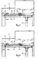
- a lifting door 1 has a frame 2 which has a guide 3 for a door leaf, not shown in this figure.
- Fig. 1 In this case, only the area of a gate page is explained in this description mostly, with a correspondingly designed frame arrangement with guide etc. is present on the other side of the door opening mirror-inverted.
- the lifting gate 1 furthermore has a drive unit 4 with a motor and a drive shaft 41, which extends over the gate width, as well as a sealing device 5.
- the drive unit 4 is fixed, that is arranged not displaceable on the frame 2.
- the guide 3 includes a lintel portion 31 which is formed in the present embodiment as a spiral and mounted on a support member 31 a. In this, the door leaf is received at open Hubtor 1 in a non-contact winding in the lintel area.
- the guide 3 further includes a vertical portion 32 in which the door leaf is present when the lifting door 1 is closed.
- a mirror-image guide is arranged at the opposite frame of the door opening.
- Fig. 1 shows the state in which the guide 3 is in the initial position, in which the door leaf can be moved from one area to the other.
- Fig. 2 shows the situation in which the guide 3 is offset on the frame 2.
- the guide 3 is displaceably mounted on the frame 2 in a manner which will be explained later in more detail.
- Fig. 2 also shows a door leaf 6 of the lifting gate 1, which in the position according to Fig. 2 completely received in the vertical portion 32 of the guide 3.
- the door leaf 6 is mounted in the guide 3 and is thus displaced horizontally together with the vertical section 32 and the guide 3, when the lifting door 1 in the position according to Fig. 2 passes.
- the offset movement takes place transversely to the door leaf plane, which is defined by the large surfaces - inner surface or outer surface - of the door leaf in the closed state.
- the sealing device 5 has Zargen Whylemente 51, which are fixed on the gate height away on each side of the door opening on the corresponding frame 2, and a lintel sealing element 52, which is attached to the lintel.
- the two vertical Zargenêtlemente 51 and the horizontally extending lintel sealing element 52 are connected to each other by gluing, so that the sealing device 5 is present as a one-piece element. This results in the corner region at the joints of the sealing elements 51 and 52 no gap and thus a reliable sealing effect.
- the door leaf 6 In the unextended position of the guide 3 and the door leaf 6 according to Fig. 1 in contrast, the door leaf 6 is at a distance from the sealing device 5. By the pressure of the door leaf 6 on the sealing device 5 in the position according to Fig. 2 a reliable seal in this area is achieved.
- the door leaf 6 has a plurality of lamellae 61, which each extend transversely across the door opening from one frame 2 to the other frame, not shown here, and are connected to one another in an angled manner.
- the fins 61 are each supported by guide rollers 62 in the lateral guides 3.
- the lamellae 61 are coupled to each other adjacent to the frames 2 hinge bands 63 on both sides, via which the driving force for the operation of the door leaf 6 is transmitted to this.
- the structure of the door leaf 6 and its interaction with the guides 3 is per se conventional nature and for example from the DE 199 15 376 A1 known.
- FIG. 3 is a plan view of the lintel of the guide 3 shown in more detail.
- Fig. 3 is the guide 3 in its normal position, that is, it is not offset in the direction of Torau Hseite against the lintel 2.
- Fig. 4 on the other hand shows the situation with staggered guide 3, in which the door leaf 6, not shown here completely present in the vertical section 32.
- the measure of the offset is in the 3 and 4 indicated by the word "HUB".
- Fig. 3 HUB 0, since there is no offset, while Fig. 4 indicates an offset by a predetermined amount.
- a linear guide 22 is shown in more detail. How out Fig. 2 it can be seen, two such linear guides 22 are provided in the region of the lintel section 31 of the guide 3, to store this by means of the support member 31a transversely to the door leaf level, ie horizontally displaceable.
- the linear guide 22 in this case has a bearing shaft 23 which is mounted displaceably in bearing bushes 33.
- a return spring 24 is also placed in the form of a compression spring, which counteracts an offset of the lintel section 31 of the guide 3 in the direction of Torau Wseite and so causes a reset of the lintel portion 31 in its initial position upon release of the actuating mechanism.
- the guides 3 are offset on both sides of the door opening in total and to the same extent on the respectively associated frame 2.
- the offset movement thus relates both to the lintel section 31 and the vertical section 32 of a guide 3, as described below with reference to FIG FIGS. 5 and 6 will be explained further.
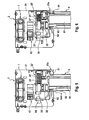
- FIGS. 5 and 6 show plan views of a frame 2 with adjacent door leaf 6 in the region of a vertical portion 32.
- Fig. 6 the offset position of the vertical portion 32 by a predetermined amount of HUB reproduces.
- Gate leaf 6 As shown in Fig. 6 press that Gate leaf 6, however, in the staggered position of the vertical portion 32 against the sealing device 5 and provides a reliable seal in the region of the side edges (as well as in the lintel area) of the door opening ago.
- FIGS. 5 and 6 also show other elements of the lifting gate 1.
- a frame housing 21 of the frame 2 can be seen from this.
- a door opening facing portion 21a of the frame 2 is closer, to which a Zargen Whylement 51 of the sealing device 5 is fixed.
- a belt drive 42 of the drive unit 4 by means of which the driving force of the motor via the drive shaft 41 is transmitted to the door leaf 6.
- the belt drive 42 interacts with a door leaf receptacle 64 on the door leaf 6, which engages at the lower end of the door leaf 6 in the region of its end element or an adjacent lamella 61.
- FIGS. 5 and 6 a linear guide 22 'for the vertical portion 32 of the guide 3 is shown.
- This linear guide 22 ' differs from that in the lintel area only in their concrete structural form, the mode of action, however, is identical.
- the vertical portion 32 is in this case by means of a bearing bush 33 'slidably mounted on a bearing shaft 23' of the linear guide 22 '.
- a return spring 24' is also placed in the form of a compression spring, which counteracts an offset of the vertical portion 32 in the direction of Torau Wseite and thus causes a resetting of the vertical portion 32 together with the lintel portion 31 at a release of the actuating mechanism. From the FIGS. 5 and 6 In this case, the offset of the vertical section 32 can also be seen in the area of the linear guide 22 '.
- Such a linear guide 22 ' is arranged on the frame 2 at least two points above the door height.
- Corresponding linear guides 22 ' are mirror images in the opposite frame. To avoid tilting the guide 3 in the course of the offset and especially for larger door heights more than two linear guides 22 'per gate page are provided.
- the offset movement is initiated by the Torblattage 64, which has a pressure section 65. This presses in the course of the closing operation of the door leaf 6 shortly before reaching the full closed position on a roller 27 which is mounted at the lower end of the actuating rod 25.
- the actuating rod 25 is in this case mounted displaceably in the longitudinal direction in the frame 2, so that it is pressed by the action of the pressure section 65 down to the footprint. This initiates a rolling movement of the deflection roller 35 along the inclined guide surface 26a. As a result, the door leaf 6 is moved in the last movement section not only down, but at the same time also towards the Torau combinée.
- Fig. 9 a schematic perspective view of a frame 2 is shown. From this, a control unit 8 for the control of the operation of the lifting door 1 can be seen. In particular shows Fig. 9 However, four linear guides 22 'for a vertical portion 32. This tilting of the vertical portion 32 is avoided. In addition, are out Fig. 9 also three operating mechanisms with one corresponding number of actuation blocks 26 and pulleys 35 recognizable. The introduced by the actuating rod 25 offset force is thus transmitted to the vertical portion 32 of the guide 3 at three points.
- Fig. 10 shows an actuating mechanism in more detail, in particular, the actuating rod 25, the storage and the roller 27 are each clearly visible. On the roller 27 of the printing section 65, not shown, acts on the Torblattage 64 and pushes them down, so that the actuating rod 25 is pulled all down.
- Fig. 10 also shows a linear guide 22 'in more detail.
- the vertical portion 32 is fixedly connected to the bearing bush 33 'which is slidably slidable on the bearing shaft 23'.
- the return spring 24 ' causes a return of the vertical portion 32, as soon as the pressure on the roller 27 is released and the likewise spring biased in the opposite direction actuating rod 25 returns to its rest position.
- the actuating blocks 26 are offset together with the actuating rod 25 so that the guide rollers 35 roll on the inclined guide surface 26a in the opposite direction and the vertical portion 32 can return to its original position.
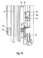
- FIGS. 11 and 12 are shown detail views of the actuating mechanism in the area at the transition from the vertical section 32 to the lintel section 31.
- Fig. 11 again shows the initial state in which the guide 3 is not offset to the outside.
- Fig. 12 on the other hand shows the staggered state of the guide 3, in which this presses against the sealing device 5.
- the actuating mechanism is formed in this area identical to the actuating mechanisms in the region of the vertical portion 32.
- an actuating block 26 is attached to the actuating rod 25 and cooperates with a guide roller 35 which sits on a Umlenkrollenitati 34.
- the deflection roller 35 rolls in the preparation of the offset or in the provision of the offset of the guide 3 on the inclined guide surface 26 a of the actuating block 26 from.
- the lintel portion 31 is offset via the carrier element 31 a together with the vertical portion 32 in a train by the action of the actuating rod 25 transversely to the Torblattebene.
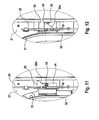
- actuating mechanism In the Fig. 13 to 16 an alternative embodiment for an actuating mechanism is shown.
- an actuating rod is dispensed with and the force for displacement of the guide is introduced at the top and bottom of a door leaf 6 '.
- actuating receptacles are arranged at these locations, wherein Fig. 13 a lower actuating receptacle 66 and Fig. 14 an upper actuating receptacle 67 shows. These have each oblique guide surfaces 66a and 67a, which cooperate with fixedly attached to a frame 2 'guide rollers.
- Fig. 15 shows a lower guide roller 28 and Fig. 16 shows an upper guide roller 29th
- the oblique guide surface 66a of the lower actuating receptacle 66 engages with the lower guide roller 28, which then rolls on it.
- the oblique guide surface 67a of the upper actuation receptacle 67 engages with the upper guide roller 29, which also rolls on it.
- the vertical portion 32 'and thus the entire guide 3 is thus indirectly offset horizontally over the door leaf 6' in this second embodiment by being taken along by the guide rollers 62 'mounted on lamellae 61' or hinge bands 63 '.
- the guide is mounted here in an identical manner by means of linear guides as the linear guides 22 and 22 'of the first embodiment of the frame 2', so that tilting of the door leaf 6 'and the guide is avoided.
- the invention allows, in addition to the illustrated embodiments, further design approaches.
- actuating mechanisms such as the actuating rod, etc. for the initiation of the offset of the guide 3, as long as a reliable operation of the lifting door 1 is made possible.
- traction elements such as timing belts, chains, ropes, etc.
- the inclination angle of the inclined guide surface 26a of the actuating blocks 26 can be selected differently depending on the application. Preferably, an inclination angle between 20 and 45 degrees is provided relative to the vertical. With the angle selection, you can influence the relationship between vertical and horizontal Torblatthub in the course of the movement. At an angle of 45 degrees, for example, the ratio is 1: 1.
- the lifting gate according to the invention can also be realized without the lintel sealing element 52, so that the sealing device 5 or 5 'then only the two lateral Zargen Whylemente 51 and 51 'has.
- a lintel sealing device according to the DE 10 2008 007 592 A1 be provided. This achieves a reliable sealing effect not only in the area of the side frames but also in the lintel area.
- the lintel portion 31 of the guide 3 is formed as a round spiral.
- an elongated spiral shape can be chosen, as for example from the DE 40 15 214 A1 has become known.
- the lintel portion 31 is formed integrally with the support member 31a.
- the introduction of force of the drive on the door leaf at the lower end of the door leaf is not mandatory.
- the door leaf drive to act on the upper end of the door leaf, so that there the driving force is introduced.
Description
Die Erfindung betrifft ein Hubtor mit einem beweglichen Torblatt und beidseits einer Toröffnung angeordneten, gebäudefesten Zargen, wobei an den Zargen aufeinander zu weisende, seitliche Führungen für das Torblatt angeordnet sind, welche jeweils einen Vertikalabschnitt und einen Sturzabschnitt aufweisen, wobei das Torblatt aus abwinkelbar miteinander verbundenen Lamellen ausgebildet ist und in geschlossenem Zustand die Toröffnung abdeckt, wobei das Torblatt in den seitlichen Führungen derart geführt ist, dass es bei geöffnetem Hubtor in den Sturzabschnitten und bei geschlossenem Hubtor in den Vertikalabschnitten der Führungen aufgenommen ist, wobei die Vertikalabschnitte der Führungen versetzbar an den Zargen gelagert sind, wodurch das Torblatt bei geschlossenem Hubtor in Richtung zur Toraußenseite versetzbar ist, und wobei das Hubtor eine Ansteuereinrichtung aufweist, welche auf eine Bewegung des Torblatts anspricht und hierauf basierend den Versatz der Vertikalabschnitte an den Zargen bewirkt.The invention relates to a lifting gate with a movable door leaf and arranged on both sides of a door opening, building-fixed frames, which are arranged on the sides facing each other, lateral guides for the door leaf, each having a vertical portion and a lintel portion, wherein the door leaf from angled connected to each other Slats is formed and covers the door opening in the closed state, wherein the door leaf is guided in the lateral guides such that it is received with the lift door open in the lintel sections and with closed lift gate in the vertical sections of the guides, wherein the vertical sections of the guides displaceable on the Sides are mounted, whereby the door leaf is displaceable in the direction of the Toraußenseite with the lift gate closed, and wherein the lifting door has a drive device which responds to a movement of the door leaf and based thereon the offset of the vertical sections a n causes the frames.
Ein Hubtor in Gestalt eines schnelllaufenden Industrietores ist beispielsweise aus der
Die Abdichtung des Bewegungsspalts zwischen dem Torblatt und der Toröffnung erfolgt beim Rolltor gemäß der
Darüber hinaus werden derartige Rolltore, wie sie aus der
Ferner sind aus der
Eine ähnliche Bauweise für ein Hubtor ist aus der
Bei derartigen Hubtorsystemen ist es jedoch nachteilig, dass die Dichtelemente jedenfalls im unteren Bereich der Toröffnung weiterhin einem erheblichen Verschleiß durch das hieran entlang gleitende Torblatt ausgesetzt sind. Damit nutzen sich die hier gegebenen Dichtelemente zwar nicht über ihre gesamte Länge hinweg ab; sie verschleißen jedoch unverändert deutlich im unteren Bereich, so dass dort keine zuverlässige Abdichtwirkung erzielbar ist. Darüber hinaus besteht über den Einsatzzeitraum der Hubtorsysteme mit geteilten Führungsabschnitten hinweg zunehmend die Gefahr, dass keine passend fluchtende Verbindung zwischen dem Sturzabschnitt und dem Vertikalabschnitt mehr herstellbar ist. Dann ist kein ordentlicher Betrieb mehr möglich.In such lifting door systems, however, it is disadvantageous that the sealing elements are at least in the lower region of the door opening continue to be exposed to considerable wear by the thereto along sliding door leaf. Although this does not take advantage of the sealing elements given here over their entire length away from; However, they continue to wear significantly in the lower region, so that there is no reliable sealing effect can be achieved. In addition, over the period of use of Hubtorsysteme with divided guide sections away increasingly the danger that no matching aligned connection between the camber portion and the vertical portion is more producible. Then no proper operation is possible.
Aus der
Nachteilig an diesem Hubtor ist dabei, dass das Torblatt im letzten Abschnitt der Schließbewegung eine schleifende Bewegung an den Rahmenelementen der Toröffnung ausführt. Dies führt zu einem erheblichen Verschleiß des Torblatts über seine gesamte Höhe hinweg. Da bei diesem bekannten Hubtor offensichtlich eine manuelle Betätigung vorgesehen ist, erscheint dies aufgrund der geringen Bewegungsgeschwindigkeit hinnehmbar. Für einen Schnelllaufbetrieb ist ein derartiges Hubtor jedoch nicht geeignet.A disadvantage of this lifting gate is that the door leaf executes a sliding movement on the frame elements of the door opening in the last section of the closing movement. This leads to a considerable wear of the door leaf over its entire height. Since a manual operation is obviously provided in this known lifting door, this seems acceptable due to the low speed of movement. For a high-speed operation, however, such a lifting door is not suitable.
Zudem unterliegt die für die Rückführung des Vertikalabschnitts eingesetzte Federeinrichtung einer erheblichen Abnutzung, da sie bei jeder Öffnungsbewegung das Eigengewicht des Vertikalabschnitts der beiden Führungen anheben muss. Von besonderer Problematik ist es hierbei, dass bei nachlassender Federkraft nicht mehr gewährleistet ist, dass zuverlässig eine fluchtender Anschluss an den Sturzabschnitt erreicht wird. Das Torblatt kann dann nicht mehr störungsfrei in den Sturzabschnitt hineinbewegt werden. Die Folge sind Beschädigungen am Torblatt sowie Probleme im Betrieb des Hubtores.In addition, the spring device used for the return of the vertical section is subject to considerable wear, since it must raise the dead weight of the vertical portion of the two guides at each opening movement. Of particular concern here is that with decreasing spring force is no longer guaranteed that a reliable connection to the lintel section is achieved. The door leaf can then no longer be moved without interference in the lintel section. The result is damage to the door leaf and problems in the operation of the lift gate.
Der Erfindung liegt daher die Aufgabe zugrunde, ein gattungsgemäßes Hubtor derart weiterzubilden, dass es mit größerer Betriebssicherheit bei zugleich verbesserter Abdichtwirkung zwischen dem Torblatt und der Toröffnung einsetzbar ist.The invention is therefore based on the object, a generic lifting gate such that it can be used with greater reliability at the same time improved sealing between the door leaf and the door opening.
Diese Aufgabe wird durch ein Hubtor mit den Merkmalen des Anspruches 1 gelöst. Dieses zeichnet sich insbesondere dadurch aus, dass das Hubtor eine Antriebseinheit für den Betrieb des Torblatts aufweist, dass das Hubtor eine Dichteinrichtung mit Zargendichtelementen aufweist, welche an den Zargen angeordnet sind, wobei diese bei geschlossenem Hubtor einen Spalt zwischen dem Torblatt und einem der Toröffnung zugewandten Abschnitt der Zargen schließen, wobei das Torblatt bei geschlossenem Hubtor gegen die Dichteinrichtung gedrückt ist, dass die Sturzabschnitte der Führungen spiralförmig ausgebildet sind, wobei das Torblatt im geöffneten Zustand des Hubtores mit berührungsfrei vorliegenden Wickellagen hierin angeordnet ist, dass die Sturzabschnitte der Führungen zusammen mit den Vertikalabschnitten der Führungen versetzbar an den Zargen gelagert sind, und dass die Führungen nur in eine Richtung quer zur Torblattebene und nicht in Bewegungsrichtung des Torblatts versetzbar sind.This object is achieved by a lifting gate with the features of
Im Rahmen der Erfindung wurde hierbei erkannt, dass sich die Dichtwirkung bereits dadurch verbessern lässt, dass man das Zusammenwirken des Torblatts mit der Dichteinrichtung in bestimmter Weise verändert. Hierzu sieht die Erfindung erstmals vor, die Führungen nur quer zur Torblattebene beweglich an der Toranordnung auszubilden, d.h. einen rein linearen Horizontalversatz anzuwenden.In the context of the invention, it has been recognized that the sealing effect can already be improved by changing the interaction of the door leaf with the sealing device in a specific manner. For this purpose, the invention provides for the first time, the guides only transversely to the door leaf form movable on the door assembly, i. to apply a purely linear horizontal offset.
Dabei wurde im Rahmen der Erfindung ferner erkannt, dass sich das Torblatt durch die Aufnahme in den Vertikalabschnitten der Führungen wie eine starre Platte verhält und somit quer zur Torblattebene eine wirksame Kraftübertragung möglich ist. Dementsprechend ist es erfindungsgemäß trotz des Torblattaufbaus aus zueinander abwinkelbaren Lamellen möglich, das Torblatt wie ein starres Element in Richtung zur Toraußenseite gegen die Dichteinrichtung zu drücken.It was further recognized in the invention that the door leaf behaves as a rigid plate by the inclusion in the vertical sections of the guides and thus an effective power transmission is possible transverse to the door leaf level. Accordingly, it is possible according to the invention despite the Torblattaufbaus from mutually angled slats to press the door leaf as a rigid element in the direction of Toraußenseite against the sealing device.
Damit kann hier eine außerordentlich zuverlässige Abdichtwirkung erreicht werden, da die Dichteinrichtung durch den ausgeübten Druck ihre Wirksamkeit besonders gut entfalten kann. Auf diese Weise wird erreicht, dass das Torblatt exakter und zuverlässiger an der Dichteinrichtung anliegt, als dies im Stand der Technik der Fall war.Thus, an extremely reliable sealing effect can be achieved here, since the sealing device can develop its effectiveness particularly well by the pressure exerted. In this way it is achieved that the door leaf rests more accurately and reliably on the sealing device, as was the case in the prior art.
Die Dichteinrichtung beim erfindungsgemäßen Hubtor wird dabei quer zu ihrer Längserstreckung beaufschlagt und nicht wie im Stand der Technik durch eine hieran entlang gleitende Bewegung. Sie unterliegt somit einem geringeren Verschleiß und erreicht dementsprechend eine höhere Lebensdauer als jene im Stand der Technik. Damit lässt sich ein besonders gut abgedichtetes und selbst im Hinblick auf die Dichteinrichtung besonders langlebiges und zuverlässiges Hubtor erzielen.The sealing device in the lifting door according to the invention is applied transversely to its longitudinal extent and not as in the prior art by a movement along it along sliding. It is thus subject to less wear and accordingly achieves a longer service life than those in the prior art. This makes it possible to achieve a particularly well-sealed and even with regard to the sealing device particularly durable and reliable lift gate.
Damit ist es möglich, auf eine schleifende Dichteinrichtung zu verzichten, so dass eine besonders hohe Lebensdauer für diese erreichbar ist. Ferner ergibt sich hieraus der Vorteil, dass die Gestaltungsfreiheit im Hinblick auf das Material der Dichteinrichtung besonders groß ist, da typischerweise mehr geeignete Dichtwerkstoffe und Dichtungsformen für gedrückte Dichtungen zur Verfügung stehen, als für schleifende Dichtungen.This makes it possible to dispense with a sliding sealing device, so that a particularly long service life can be achieved for them. Furthermore, this results in the advantage that the freedom of design with respect to the material of the sealing device is particularly large, since typically more suitable sealing materials and seal shapes for depressed seals are available, as for sliding seals.
Darüber hinaus zeichnet sich das erfindungsgemäße Hubtor durch eine besonders hohe Betriebssicherheit aus. Im Gegensatz zum nächstkommenden Stand der Technik
Hierdurch ist das erfindungsgemäße Hubtor auch besonders geeignet für spezielle Anwendungsfälle wie z. B. als Tiefkühltor, bei welchem sich auf Grund der Umgebungsbedingungen ein fluchtendes Ausrichten von Sturzabschnitt und Vertikalabschnitt im Betrieb verzögern könnte. Dieser Nachteil aus dem Stand der Technik ist nun überwunden und die Bauweise des Hubtores kann erfindungsgemäß einfacher gehalten werden.As a result, the lifting door according to the invention is also particularly suitable for special applications such. B. as Tiefkühltor, in which due to the environmental conditions an aligned alignment of lintel section and vertical section could delay in operation. This disadvantage of the prior art is now overcome and the construction of the lifting gate can be kept simpler according to the invention.
Von Vorteil ist es zudem, dass das Hubtor eine Ansteuereinrichtung aufweist, welche auf eine Bewegung des Torblatts anspricht und hierauf basierend den Versatz der Vertikalabschnitte an den Zargen bewirkt. Dann lässt sich dieser Vorgang mit geringem technologischen Aufwand automatisieren, wobei zudem sichergestellt ist, dass dieser Versatz nur dann erfolgt, wenn das Torblatt vollständig in die Vertikalabschnittte eingetreten ist. Hierdurch lässt sich mit besonders einfachem baulichen Aufwand eine sehr zuverlässige Hubtoranordnung erzielen.It is also advantageous that the lifting gate has a drive device which responds to a movement of the door leaf and, based thereon, effects the offset of the vertical sections on the sides. Then this process can be automated with little technological effort, and it is also ensured that this offset takes place only when the door leaf has completely entered the vertical section. As a result, a very reliable Hubtoranordnung can be achieved with a particularly simple construction effort.
Da die Relativbewegung der beiden Führungen gegenüber den Zargen nur horizontal erfolgt, ergibt sich zudem eine sehr geringe Störanfälligkeit des erfindungsgemäßen Hubtores.Since the relative movement of the two guides relative to the frames only takes place horizontally, also results in a very low susceptibility to failure of the invention Hubtores.
Zudem erlaubt das erfindungemäße Hubtor durch seine permanente Führung in den seitlichen Führungen wie auch durch das berührungsfreie Wickeln des Torblatts im spiralförmigen Sturzabschnitt einen zuverlässigen Schnelllaufbetrieb, wie er für industrielle Einsatzzwecke in der Regel gewünscht ist.In addition, the inventive Hubtor allowed by its permanent leadership in the side guides as well as by the non-contact winding of the door leaf in the spiral lintel section reliable high-speed operation, as it is usually desired for industrial applications.
Darüber hinaus ist von Vorteil, dass das erfindungsgemäße Hubtor besonders kompakt aufgebaut sein kann. Insbesondere sind beim Übergang von Vertikalabschnitt der Führung zum Sturzabschnitt im Gegensatz zum Stand der Technik keine besonderen Zugeständnisse in konstruktiver Hinsicht erforderlich. Während der Stand der Technik hier noch entsprechende Pufferführungslängen in den Führungsabschnitten vorsah, um der Anordnung im Zuge der Rückstellung der Führungsabschnitte in eine fluchtende Konstellation hinreichend Zeit dafür zu geben, besteht hier erfindungsgemäß keine Trennstelle, so dass der Sturzabschnitt unmittelbar auf den Vertikalabschnitt aufsetzt. Insofern ist es erfindungsgemäß im Wesentlichen auch unerheblich, an welcher Position sich die letzte, oberste Führungsrolle des Torblatts bei geschlossenem Hubtor befindet, das heißt ob diese sich noch am Ausgang des Sturzabschnitts befindet oder bereits innerhalb des Vertikalabschnitts, solange eine hinreichende Dichtwirkung an der Toröffnung erzielt wird.In addition, it is advantageous that the lifting door according to the invention can be constructed particularly compact. In particular, in the transition from the vertical section of the guide to the lintel section in contrast to the prior art, no special concessions in terms of design are required. While the prior art still provided here corresponding buffer guide lengths in the guide sections to give the arrangement in the course of the provision of the guide sections in an aligned constellation sufficient time for this, there is no separation point according to the invention, so that the lintel section directly on the vertical section touches. In this respect, it is inventively essentially irrelevant, at which position is the last, uppermost leadership role of the door leaf with the lift gate closed, that is, whether this is still at the exit of the lintel section or already within the vertical section, as long as a sufficient sealing effect is achieved at the door opening.
Hierbei ist zwar aus der
Mit dieser bekannten Bauweise gemäß der
Vorteilhafte Weiterbildungen des erfindungsgemäßen Hubtores sind Gegenstand der abhängigen Ansprüche 2 bis 7.Advantageous developments of the invention Hubtores are the subject of the
So können die Sturzabschnitte der Führungen jeweils auf einem Trägerelement angeordnet sein, wobei die Trägerelemente mit den darauf angeordneten Sturzabschnitten der Führungen zusammen mit den Vertikalabschnitten der Führungen versetzbar an den Zargen gelagert sind. Dann ist eine besonders zuverlässige Führung der spiralförmigen Sturzabschnitte möglich, wodurch sich die Betriebssicherheit des erfindungsgemäßen Hubtores weiter verbessert. Insbesondere kann so ein mögliches Verkanten der Führungen beim Versetzen noch zuverlässiger vermieden werden.Thus, the lintel sections of the guides can each be arranged on a carrier element, wherein the carrier elements with the lintel sections of the guides arranged thereon can be displaced together with the vertical sections of the guides are stored on the sides. Then a particularly reliable guidance of the spiral lintel sections is possible, whereby the reliability of the lifting door according to the invention further improved. In particular, such a possible tilting of the guides during displacement can be avoided even more reliably.
Ferner ist es möglich, dass die Ansteuereinrichtung eine Torblattaufnahme ist, welche im Bereich eines Abschlusselements des Torblatts angeordnet ist und die Antriebskraft der Antriebseinheit auf das Torblatt einleitet. Hierdurch lässt sich die Erfindung mit besonders geringem konstruktiven Aufwand realisieren, da eine derartige Torblattaufnahme bei herkömmlichen Hubtoren zumeist ohnehin vorhanden ist. Insbesondere ist es ohne einer oder allenfalls nur einer sehr geringen konstruktiven Anpassung der Torblattaufnahme möglich, diese als Ansteuereinrichtung zu nutzen. Ferner wird hierdurch die Antriebskraft der Antriebseinheit besonders effektiv zur Einleitung der Versatzbewegung der Vertikalabschnitte an den Zargen genutzt.Furthermore, it is possible that the drive device is a Torblattaufnahme, which is arranged in the region of a closing element of the door leaf and initiates the driving force of the drive unit on the door leaf. As a result, the invention can be realized with particularly low design effort, since such a Torblattaufnahme is usually present anyway in conventional lifting gates. In particular, it is possible without one or at most only a very small structural adjustment of the Torblattaufnahme to use this as a drive device. Furthermore, the driving force of the drive unit is thereby used particularly effectively for initiating the offset movement of the vertical sections on the frames.
Gemäß einer Ausführungsvariante kann die Ansteuereinrichtung mit einer zargenseitigen Betätigungseinrichtung zusammenwirken, welche den Versatz der Führungen über Versatzmechanismen einleitet, wobei wenigstens zwei, vorzugsweise zumindest drei und insbesondere mehr als vier Versatzmechanismen an jeder Torseite vorliegen. Damit wird die gleichzeitige Einleitung einer Kraft zum Versetzen der Vertikalabschnitte und der Sturzabschnitte der Führungen zur Toraußenseite hin an mehreren Stellen über die Torblatthöhe hinweg ermöglicht. Ein Verkanten der Führungen kann so zuverlässig unterbunden werden, da deren Bewegung im Sinne eines horizontalen Parallelversatzes zugleich über die gesamte Längserstreckung der Führungen im Bereich der Toröffnung erfolgt. Dementsprechend sind an jeder Torseite wenigstens zwei Versatzmechanismen angeordnet, die zumindest jeweils im oberen und unteren Bereich der Vertikalabschnitte der Führungen angreifen. In Abhängigkeit von der Torhöhe kann es jedoch auch sachgerecht sein, drei, vier oder auch mehr Versatzmechanismen an jeder Torseite vorzusehen, um ein gleichmäßiges Andrücken des in den Vertikalabschnitten der Führungen aufgenommenen und hiermit zugleich bewegten Torblatts gegen die Dichteinrichtung zu erzielen. Gerade bei Torhöhen über fünf Metern ist es zumeist sachgerecht, mehr als vier Versatzmechanismen an jeder Torseite einzusetzen. Dabei ist die Betätigungseinrichtung vorzugsweise als eine Betätigungsstange ausgebildet, welche mit den Versatzmechanismen zusammenwirkt und eine gleichzeitige Betätigung derselben erlaubt. Hierdurch wird mit einfachen technologischen Mitteln eine zuverlässige Betätigungsweise erzielt.According to one embodiment variant, the activation device can cooperate with a frame-side actuating device which initiates the offset of the guides via offset mechanisms, at least two, preferably at least three, and in particular more than four, offset mechanisms being present on each side of the gate. Thus, the simultaneous introduction of a force for displacing the vertical sections and the lintel sections of the guides towards the outside of the door is made possible at several points beyond the door leaf height. A tilting of the guides can be reliably prevented because their movement in the sense of a horizontal parallel offset at the same time over the entire longitudinal extension of the guides in the gate opening. Accordingly, at least two offset mechanisms are arranged on each door side, which engage at least in each case in the upper and lower regions of the vertical sections of the guides. Depending on the height of the door, however, it may also be appropriate to provide three, four or even more offset mechanisms on each door side in order to achieve a uniform pressing of the door leaf accommodated in the vertical sections of the guides and at the same time moving against the sealing device. Especially with door heights over five meters, it is usually appropriate to use more than four offset mechanisms on each side of the goal. In this case, the actuating device is preferably designed as an actuating rod, which cooperates with the offset mechanisms and allows simultaneous actuation thereof. As a result, a reliable operation is achieved with simple technological means.
Alternativ ist es auch möglich, dass die Ansteuereinrichtung beidseits am oberen und unteren Ende des Torblatts befestigte Betätigungsaufnahmen aufweist, in welche zargenseitig gelagerte Führungsrollen eingreifen, um den Versatz der Führungen an den Zargen im Zuge des Schließvorganges des Torblatts herzustellen. Diese Ausführungsvariante zeichnet sich durch einen besonders geringen konstruktiven Aufwand aus, da hier auf eine Betätigungsstange in jeder Zarge etc. verzichtet werden kann. Allerdings ist dann typischerweise nur ein Krafteintrag am oberen und unteren Ende des Torblatts vorgesehen. Hierbei werden die Führungen mittelbar über die Versatzbewegung des Torblatts in Richtung zur Toraußenseite der Dichteinrichtung versetzt. Gerade bei Hubtoren mit Torblättern von vergleichsweise geringer Höhe stellt diese alternative Ausgestaltung einer Ansteuereinrichtung jedoch eine kostengünstige und praktikable Variante dar.Alternatively, it is also possible that the control device has on both sides at the upper and lower end of the door leaf mounted actuating receptacles, in which frame side mounted guide rollers engage to produce the offset of the guides to the frames in the course of the closing operation of the door leaf. This embodiment is characterized by a particularly low design effort, since it can be dispensed with an actuating rod in each case, etc. here. However, then typically only a force input is provided at the top and bottom of the door leaf. In this case, the guides are offset indirectly via the offset movement of the door leaf in the direction of the Toraußenseite the sealing device. However, in the case of lifting gates with door leaves of comparatively low height, this alternative embodiment of a control device represents a cost-effective and practicable variant.
In einer weiteren Alternative ist es möglich, dass die Ansteuereinrichtung eine Steuereinheit ist, welche eine separate Antriebseinrichtung ansteuert, mittels welcher der Versatz der Führungen an den Zargen nach Abschluss der Schließbewegung des Torblatts herstellbar ist. Diese Ausführungsvariante erfordert den geringsten baulichen Änderungsaufwand am Torblatt bzw. Torblattantrieb gegenüber herkömmlichen Bauweisen und lässt sich steuerungstechnisch zudem sehr zuverlässig und mit einfachen Mitteln realisieren. Dabei weist die separate Antriebseinrichtung im Bereich von jeder Zarge wenigstens zwei, vorzugsweise zumindest drei und insbesondere mehr als vier Stellglieder auf, welche den Versatz der Führungen an den Zargen herstellen. Die Anzahl der Stellglieder ist auch in dieser Ausführungsvariante in der Regel anhand der gegebenen Torhöhe des erfindungsgemäßen Hubtores zu wählen, wobei eine größere Torhöhe generell mit einer größeren Anzahl an Stellgliedern verbunden sein dürfte.In a further alternative, it is possible for the activation device to be a control unit which actuates a separate drive device, by means of which the offset of the guides on the frame can be produced after completion of the closing movement of the door leaf. This embodiment requires the least amount of structural change on Torblatt or Torblattantrieb compared to conventional designs and can also control technology very reliable and implement with simple means. In this case, the separate drive means in the region of each frame at least two, preferably at least three and in particular more than four actuators, which produce the offset of the guides on the sides. The number of actuators is also to be selected in this embodiment usually on the basis of the given door height of the invention Hubtores, with a larger door height should generally be associated with a larger number of actuators.
Zudem kann die Dichteinrichtung ferner ein Sturzdichtelement aufweisen, welches im Torsturzbereich angeordnet ist und einen dort vorhandenen Bewegungsspalt zwischen dem Torsturz und dem Torblatt bei versetztem Torblatt schließt. Damit lässt sich die Abdichtwirkung am erfindungsgemäßen Hubtor noch weiter verbessern. Insbesondere ist es auch möglich, dass das Sturzdichtelement mit den seitlichen Zargendichtelementen verbunden ist, wodurch sich ein Spalt im Stoßbereich dieser Dichtelemente vermeiden lässt. Das Sturzdichtelement und die beiden Zargendichtelemente können dabei einstückig, z.B. in Gestalt einer Schlauchdichtung, ausgebildet oder auch an den aufeinander stossenden Enden miteinander verschweißt bzw. verklebt sein.In addition, the sealing device may further comprise a lintel sealing element, which is arranged in the lintel area and closes an existing there movement gap between the lintel and the door leaf with offset door leaf. This makes it possible to further improve the sealing effect on the lifting door according to the invention. In particular, it is also possible that the lintel sealing element is connected to the lateral Zargendichtelementen, whereby a gap in the joint area of these sealing elements can be avoided. The lintel sealing element and the two frame sealing elements can be made in one piece, e.g. in the form of a hose seal, formed or even welded or glued together at the abutting ends.
Gemäß einem weiteren Aspekt der vorliegenden Erfindung wird nach Anspruch 8 eine Zarge für ein erfindungsgemäßes Hubtor bereitgestellt, die eine Führung für ein Torblatt mit einem Vertikalabschnitt und einem Sturzabschnitt aufweist, wobei der Vertikalabschnitt der Führung versetzbar an der Zarge gelagert ist. Dabei zeichnet sich diese Zarge dadurch aus, dass sie ein Zargendichtelement einer Dichteinrichtung aufweist, welches bei geschlossenem Hubtor einen Spalt zwischen dem Torblatt und einem der Toröffnung zugewandten Abschnitt der Zarge schließt, dass der Sturzabschnitt der Führung spiralförmig ausgebildet und zusammen mit dem Vertikalabschnitt der Führung versetzbar an der Zarge gelagert ist, und dass die Führung nur in eine Richtung quer zur Torblattebene und nicht in Bewegungsrichtung des Torblatts versetzbar ist.According to a further aspect of the present invention, according to claim 8, a frame for a lifting gate according to the invention is provided which has a guide for a door leaf with a vertical portion and a lintel portion, wherein the vertical portion of the guide is displaceably mounted on the frame. In this case, this frame is characterized by the fact that it has a Zargendichtelement a sealing device which closes a closed gap between the door leaf and a door opening facing portion of the frame when the lift gate is closed, that the lintel portion of the guide formed spirally and displaceable together with the vertical portion of the guide is mounted on the frame, and that the guide is displaceable only in a direction transverse to the Torblattebene and not in the direction of movement of the door leaf.
Mittels dieser Zarge lassen sich analog die oben im Hinblick auf das erfindungsgemäße Hubtor erläuterten Vorteile erzielen. Dabei stellt die Zarge zudem ein Nachrüst- bzw. Umrüstteil für herkömmliche Hubtore dar, mittels dem diese in der erfindungsgemäßen Weise verbessert werden können.By means of this frame, the advantages explained above with regard to the lifting door according to the invention can be achieved analogously. The frame also represents a retrofit or conversion part for conventional lift gates, by means of which they can be improved in the manner according to the invention.
Dabei lässt sich die erfindungsgemäße Zarge durch die entsprechenden Detailmerkmale aus den abhängigen Ansprüchen 2 bis 7 weiterbilden, wobei hierdurch ebenfalls die oben erläuterten Vorteile ermöglicht werden.In this case, the frame according to the invention can be further developed by the corresponding detail features of the
Gemäß noch einem weiteren Aspekt der vorliegenden Erfindung wird nach Anspruch 10 ein Verfahren zum Schließen eines Spalts an einem Hubtor aufgezeigt, welches sich besonders vorteilhaft am erfindungsgemäßen Hubtor anwenden lässt. Dieses Verfahren ist dabei durch die Schritte gekennzeichnet: Bewegen des Torblatts in seine Schließstellung, und Versetzen der Sturzabschnitte der Führungen zusammen mit den Vertikalabschnitten der Führungen quer zur Torblattebene im Zuge der Schließbewegung oder im Anschluss hieran in Richtung zur Toraußenseite, ohne eine Bewegung der Führungen in Bewegungsrichtung des Torblatts, wodurch das Torblatt gegen die Dichteinrichtung gedrückt wird.According to yet another aspect of the present invention, according to claim 10, a method for closing a gap at a lifting gate is disclosed, which can be used particularly advantageously on the lifting door according to the invention. This method is characterized by the steps of: moving the door leaf to its closed position, and displacing the camber sections of the guides together with the vertical sections of the guides transversely to the door leaf plane in the course of the closing movement or thereafter towards the door outer side without movement of the guides in Direction of movement of the door leaf, whereby the door leaf is pressed against the sealing device.
Durch dieses erfindungsgemäße Verfahren lässt sich in vorteilhafter Weise eine verbesserte Abdichtwirkung zwischen dem Torblatt und der Toröffnung herstellen, wobei zudem ein sehr geringer Verschleiß an der Dichteinrichtung auftritt. Zudem tritt im Betrieb im Gegensatz zum Stand der Technik kein Versatz zwischen dem Vertikalabschnitt und dem Sturzabschnitt der Führungen auf, wodurch das erfindungsgemäße Hubtor besonders betriebssicher eingesetzt werden kann. Das erfindungsgemäße Verfahren führt daher zu einem besonders langlebigen und zuverlässigen Einsatz eines erfindungsgemäßen Hubtores auch bei hohen Bewegungsgeschwindigkeiten von z.B. 3 m/s.By means of this method according to the invention, it is advantageously possible to produce an improved sealing effect between the door leaf and the door opening, wherein, in addition, very little wear occurs on the sealing device. In addition, in contrast to the prior art, no offset occurs between the vertical section and the lintel section of the guides during operation, as a result of which the lifting gate according to the invention can be used particularly reliably. The inventive method therefore leads to a particularly durable and reliable use of a lifting door according to the invention, even at high speeds of movement of e.g. 3 m / s.
Das erfindungsgemäße Hubtor wird nachfolgend in Ausführungsbeispielen anhand der Figuren der Zeichnung näher erläutert. Es zeigt:
- Fig. 1
- eine Seitenansicht auf den Bereich einer Zarge eines erfindungsgemäßen Hubtores, wobei das Torblatt zur Verdeutlichung weggelassen ist und die Führung in ihrer Grundstellung zum Betrieb des Torblatts vorliegt;
- Fig. 2
- eine gegenüber
Fig. 1 dahingehend abgewandelte Ansicht, dass die Führung in Richtung zur Toraußenseite versetzt ist, wobei hier das Torblatt mit eingezeichnet ist; - Fig. 3
- eine Draufsicht auf den Sturzabschnitt der Führung bei nicht versetzter Führung;
- Fig. 4
- eine Darstellung ähnlich
Fig. 3 , wobei die Führung gegenüber der Stellung inFig. 3 versetzt ist; - Fig. 5
- eine Draufsicht auf den Vertikalabschnitt der Führung des erfindungsgemäßen Hubtors mit nicht versetzter Führung;
- Fig. 6
- eine Darstellung ähnlich
Fig. 5 , wobei jedoch die Führung zusammen mit dem Torblatt in Richtung zur Toraußenseite versetzt ist; - Fig. 7
- ein Detail aus einer Seitenansicht des erfindungsgemäßen Hubtores im Bereich von dessen Aufstandsfläche bei nicht versetzter Führung;
- Fig. 8
- eine Darstellung ähnlich
Fig. 7 , wobei die Führung zur Toraußenseite versetzt ist; - Fig. 9
- eine schematische perspektivische Ansicht eines Zargenbereichs am erfindungsgemäßen Hubtor;
- Fig. 10
- eine Detailansicht der Lagerung des Vertikalabschnitts der Führung an der Zarge;
- Fig. 11
- eine vergrößerte Detailansicht einer Zarge im Übergangsbereich vom Vertikalabschnitt zum Sturzabschnitt bei nicht versetzter Führung;
- Fig. 12
- eine Darstellung ähnlich wie
Fig. 11 , wobei hier die Führung versetzt ist; - Fig. 13
- eine schematische perspektivische Darstellung einer unteren Betätigungsaufnahme für einen Betätigungsmechanismus gemäß einer zweiten Ausführungs form;
- Fig. 14
- eine schematische perspektivische Ansicht einer oberen Betätigungsaufnahme für einen Betätigungsmechanismus gemäß der zweiten Ausführungsform;
- Fig. 15
- eine schematische perspektivische Ansicht einer unteren Führungsrolle für den Betätigungsmechanismus gemäß der zweiten Ausführungsform; und
- Fig. 16
- eine schematische perspektivische Ansicht einer oberen Führungsrolle für den Betätigungsmechanismus gemäß der zweiten Ausführungsform.
- Fig. 1
- a side view of the region of a frame of a lifting door according to the invention, wherein the door leaf is omitted for clarity and the guide is in its normal position for operation of the door leaf;
- Fig. 2
- one opposite
Fig. 1 to the effect modified view that the guide is offset towards the Toraußenseite, in which case the door leaf is drawn with; - Fig. 3
- a plan view of the camber portion of the guide in non-offset guide;
- Fig. 4
- a representation similar
Fig. 3 , with the guide opposite the position inFig. 3 is offset; - Fig. 5
- a plan view of the vertical portion of the guide of the lifting door according to the invention with non-offset guide;
- Fig. 6
- a representation similar
Fig. 5 but wherein the guide is offset together with the door leaf in the direction of Toraußenseite; - Fig. 7
- a detail of a side view of the invention Hubtores in the region of its footprint with non-offset guide;
- Fig. 8
- a representation similar
Fig. 7 wherein the guide is offset to the Toraußenseite; - Fig. 9
- a schematic perspective view of a Zargenbereichs at Hubtor invention;
- Fig. 10
- a detailed view of the storage of the vertical portion of the guide on the frame;
- Fig. 11
- an enlarged detail view of a frame in the transition region from the vertical section to the lintel section with non-offset guide;
- Fig. 12
- a representation similar to
Fig. 11 , where the guide is offset here; - Fig. 13
- a schematic perspective view of a lower actuating receptacle for an actuating mechanism according to a second embodiment form;
- Fig. 14
- a schematic perspective view of an upper actuating receptacle for an actuating mechanism according to the second embodiment;
- Fig. 15
- a schematic perspective view of a lower guide roller for the actuating mechanism according to the second embodiment; and
- Fig. 16
- a schematic perspective view of an upper guide roller for the actuating mechanism according to the second embodiment.
Gemäß der Darstellung in
Die Führung 3 enthält einen Sturzabschnitt 31, der im vorliegenden Ausführungsbeispiel als Spirale ausgebildet und auf einem Trägerelement 31 a befestigt ist. In diesem wird das Torblatt bei geöffnetem Hubtor 1 in einem berührungsfreien Wickel im Torsturzbereich aufgenommen. Die Führung 3 enthält ferner einen Vertikalabschnitt 32, in dem das Torblatt bei geschlossenem Hubtor 1 vorliegt. An der gegenüberliegenden Zarge der Toröffnung ist eine spiegelbildlich ausgebildete Führung angeordnet.The
Die Führung 3 ist versetzbar und hierzu horizontal verschiebbar an der Zarge 2 gelagert.
Hierdurch drückt das Torblatt 6 gegen die Dichteinrichtung 5, welche im vorliegenden Ausführungsbeispiel als Schlauchdichtung ausgebildet ist. Die Dichteinrichtung 5 weist Zargendichtelemente 51, die über die Torhöhe hinweg an jeder Seite der Toröffnung an der entsprechenden Zarge 2 befestigt sind, sowie ein Sturzdichtelement 52 auf, welches am Torsturz befestigt ist. Die beiden vertikalen Zargendichtelemente 51 und das horizontal verlaufende Sturzdichtelement 52 sind miteinander durch Verkleben verbunden, so dass die Dichteinrichtung 5 als einteiliges Element vorliegt. Damit ergibt sich auch im Eckbereich an den Stoßstellen der Dichtelemente 51 bzw. 52 kein Spalt und somit eine zuverlässige Abdichtwirkung. In der nicht versetzten Stellung der Führung 3 bzw. des Torblatts 6 gemäß
Wie aus
In den
In den
Dabei werden die Führungen 3 zu beiden Seiten der Toröffnung insgesamt und im gleichen Maße an der jeweils zugehörigen Zarge 2 versetzt. Die Versatzbewegung betrifft somit sowohl den Sturzabschnitt 31 als auch den Vertikalabschnitt 32 einer Führung 3, wie nachfolgend anhand der
Die
Die
Darüber hinaus befindet sich innerhalb der Zarge 2 ein Riementrieb 42 der Antriebseinheit 4, mittels welchem die Antriebskraft des Motors über die Antriebswelle 41 auf das Torblatt 6 übertragen wird. Der Riementrieb 42 wirkt hierzu mit einer Torblattaufnahme 64 am Torblatt 6 zusammen, welche am unteren Ende des Torblatts 6 im Bereich von dessen Abschlusselement oder einer benachbarten Lamelle 61 angreift.In addition, located within the
Darüber hinaus ist in
Eine derartige Linearführung 22' ist an wenigstens zwei Stellen über die Torhöhe hinweg an der Zarge 2 angeordnet. Entsprechende Linearführungen 22' finden sich spiegelbildlich auch in der gegenüberliegenden Zarge. Zur Vermeidung von Verkantungen der Führung 3 im Zuge des Versatzes und insbesondere bei größeren Torhöhen sind auch mehr als zwei Linearführungen 22' pro Torseite vorgesehen.Such a linear guide 22 'is arranged on the
Aus den
Die Versatzbewegung wird dabei durch die Torblattaufnahme 64 eingeleitet, welche einen Druckabschnitt 65 aufweist. Dieser drückt im Zuge des Schließvorganges des Torblattes 6 kurz vor Erreichen der vollständigen Schließstellung auf eine Rolle 27, welche am unteren Ende der Betätigungsstange 25 gelagert ist. Die Betätigungsstange 25 ist hierbei in ihrer Längsrichtung verschieblich in der Zarge 2 gelagert, so dass sie durch die Einwirkung des Druckabschnitts 65 nach unten zur Aufstandsfläche hin gedrückt wird. Dies leitet eine Abrollbewegung der Umlenkrolle 35 entlang der schrägen Führungsfläche 26a ein. Hierdurch wird das Torblatt 6 im letzten Bewegungsabschnitt nicht nur nach unten, sondern zugleich auch in Richtung zur Toraußenseite hin bewegt.The offset movement is initiated by the
In
In den
Auf diese Weise wird der Sturzabschnitt 31 über das Trägerelement 31 a gemeinsam mit dem Vertikalabschnitt 32 in einem Zuge durch die Einwirkung der Betätigungsstange 25 quer zur Torblattebene versetzt.In this way, the
In den
Im Zuge des Schließvorganges des Torblatts 6' gelangt die schräge Führungsfläche 66a der unteren Betätigungsaufnahme 66 in Eingriff mit der unteren Führungsrolle 28, welche dann hierauf abrollt. Im Wesentlichen zugleich gelangt die schräge Führungsfläche 67a der oberen Betätigungsaufnahme 67 in Eingriff mit der oberen Führungsrolle 29, welche ebenfalls hieran abrollt. Hierdurch ergibt sich ein Versatz des Torblatts 6' gegenüber der Zarge 2', wodurch das Torblatt 6' zusammen mit einem Vertikalabschnitt 32' in Richtung zur Toraußenseite bewegt wird. Der Vertikalabschnitt 32' und damit die gesamte Führung 3 wird in dieser zweiten Ausführungsform somit mittelbar über das Torblatt 6' horizontal versetzt, indem er durch die an Lamellen 61' bzw. Scharnierbändern 63' gelagerten Führungsrollen 62' mitgenommen wird. Auch hierdurch wird ein in den
Im übrigen ist die Führung hier in an sich identischer Weise mittels Linearführungen wie den Linearführungen 22 bzw. 22' der ersten Ausführungsform an der Zarge 2' gelagert, so dass ein Verkanten des Torblatts 6' bzw. der Führung vermieden wird.Moreover, the guide is mounted here in an identical manner by means of linear guides as the
Die Erfindung lässt neben den erläuterten Ausführungsformen weitere Gestaltungsansätze zu.The invention allows, in addition to the illustrated embodiments, further design approaches.
So ist es auch möglich, andere Arten von Betätigungsmechanismen als die Betätigungsstange etc. für die Einleitung des Versatzes der Führung 3 einzusetzen, solange ein zuverlässiger Betrieb des Hubtores 1 ermöglicht wird. Beispiele hierfür sind Zugorgane wie Zahnriemen, Ketten, Seile etc.So it is also possible to use other types of actuating mechanisms than the actuating rod, etc. for the initiation of the offset of the
Darüber hinaus ist es jedoch auch möglich, separate Antriebseinrichtungen anstelle der erläuterten Betätigungsmechanismen einzusetzen und den Versatz der Sturz- und Vertikalabschnitte der Führungen an den Zargen unabhängig von der Bewegungsenergie des Torblatts herzustellen. Diese Antriebseinrichtungen könnten beispielsweise Stellmotoren sein oder motorisch angetriebene separate Stellglieder anderer Art, mittels welchen an einer vorbestimmten Anzahl größer als zwei Stellen über die Torhöhe hinweg eine Versatzbewegung auf den Sturz- und Vertikalabschnitt bzw. das Torblatt eingeleitet wird. Diese separaten Antriebseinrichtungen können zudem durch die gleiche Steuereinheit wie das Hubtor 1 an sich oder auch durch eine separate, ergänzend hierzu angeordnete und vorzugsweise steuerungstechnisch hiermit verbundene Steuereinheit betrieben werden. Eine solche Steuereinheit kann dabei durch eine Ansteuereinrichtung angesteuert werden, welche durch elektrische, elektronische, optische Mittel etc. auf eine bestimmte Torblattbewegung reagiert.In addition, however, it is also possible to use separate drive means instead of the explained actuating mechanisms and to produce the offset of the camber and vertical sections of the guides on the frames independently of the kinetic energy of the door leaf. These drive devices could for example be servomotors or motor-driven separate actuators of another type, by means of which at a predetermined number greater than two points beyond the door height, an offset movement on the lintel and vertical section or the door leaf is initiated. These separate drive devices can also be operated by the same control unit as the lifting
Ferner kann der Neigungswinkel der schrägen Führungsfläche 26a der Betätigungsklötze 26 je nach Anwendungsfall unterschiedlich gewählt werden. Bevorzugt ist ein Neigungswinkel zwischen 20 und 45 Grad gegenüber der Vertikalen vorgesehen. Mit der Winkelauswahl kann man dabei das Verhältnis zwischen vertikalem und horizontalem Torblatthub im Zuge der Bewegung beeinflussen. Bei einem Winkel von 45 Grad ist das Verhältnis beispielsweise 1:1.Further, the inclination angle of the
Das erfindungsgemäße Hubtor kann zudem auch ohne das Sturzdichtelement 52 realisiert werden, so dass die Dichteinrichtung 5 bzw. 5' dann lediglich die beiden seitlichen Zargendichtelemente 51 bzw. 51' aufweist. In diesem Falle kann alternativ eine Torsturz-Abdichteinrichtung gemäß der
Im gezeigten Ausführungsbeispiel ist der Sturzabschnitt 31 der Führung 3 als Rundspirale ausgebildet. Stattdessen kann jedoch auch eine lang gestreckte Spiralform gewählt werden, wie sie beispielsweise aus der
In einer abgewandelten Ausführungsform ist es ferner auch möglich, dass der Sturzabschnitt 31 einstückig mit dem Trägerelement 31a ausgebildet ist.In a modified embodiment, it is also possible that the
Ferner erfolgt in den gezeigten Ausführungsbeispielen die Krafteinleitung des Antriebs auf das Torblatt am unteren Ende des Torblatts. Dies ist jedoch nicht zwingend erforderlich. Bei einer Bauweise beispielsweise gemäß der
Claims (10)
- A lifting door (1) comprising a movable door leaf (6; 6') and structure-mounted frames (2; 2') arranged on both sides of a door opening,
wherein lateral guides (3) for the door leaf (6; 6') which face each other and which each comprise a vertical section (32; 32') and a lintel section (31) are arranged on the frames (2; 2'),
wherein the door leaf (6; 6') is designed of slats (61; 61') being connected to one another so as to bend and covers the door opening in the closed condition,
wherein the door leaf (6; 6') is guided in the lateral guides (3) such that it is accommodated in the lintel sections (31) when the lifting door (1) is open and in the vertical sections (32; 32') of the guides (3) when the lifting door (1) is closed, wherein the vertical sections (32; 32') of the guides (3) are displaceably mounted on the frames (2; 2'), so that the door leaf (6; 6') is displaceable in a direction to the outer side of the door when the lifting door (1) is closed, and
wherein the lifting door (1) comprises a trigger device responding to a movement of the door leaf (6; 6') and, based thereon, causing the displacement of the vertical sections (32; 32') at the frames (2; 2'),
characterized in
that the lifting door comprises a drive unit (4) for the operation of the door leaf (6; 6'),
that the lifting door comprises a sealing assembly (5; 5') with frame sealing elements (51; 51') arranged at the frames (2; 2'), wherein they close a gap between the door leaf (6; 6') and a section (21a) of the frames (2; 2') facing the door opening when the lifting door (1) is closed, wherein the door leaf (6; 6') is pressed against the sealing assembly (5; 5') when the lifting door (1) is closed,
that the lintel sections (31) of the guides (3) are designed to be spiral, wherein the door leaf (6; 6'), in the open condition of the lifting door (1), is arranged therein with touch-free winding layers,
that the lintel sections (31) of the guides (3), together with the vertical sections (32; 32') of the guides (3), are displaceably mounted on the frames (2; 2'), and
that the guides (3) can only be displaced in a direction that is perpendicular to the door leaf plane, but not in a moving direction of the door leaf (6; 6'). - The lifting door according to claim 1, characterized in that the lintel sections (31) of the guides (3) are each arranged on a carrier element (31a), and that the carrier elements (31a) with the lintel sections (31) of the guides (3) arranged thereon, together with the vertical sections (32; 32') of the guides (3), are displaceably mounted on the frames (2; 2').
- The lifting door according to claims 1 or 2, characterized in that the trigger device is a door leaf accommodation (64) arranged in the region of an end element of the door leaf (6) and introduces the drive force of the drive unit (4) on the door leaf (6).
- The lifting door according to any of claims 1 to 3, characterized in that the trigger device cooperates with a frame-side actuator initiating the displacement of the guides (3) via displacement mechanisms, wherein at least two, preferably at least three, and in particular more than four displacement mechanisms are available at each side of the door, wherein the actuator preferably is an actuating rod (25).
- The lifting door according to claim 1, characterized in that the trigger device comprises actuating accommodations (66, 67) attached at both sides at the upper and lower ends of the door leaf (6'), into which frame-side mounted guide rollers (28, 29) engage to establish the displacement of the guides (3) at the frames (2') in the course of the closing process of the door leaf (6').
- The lifting door according to claim 1, characterized in that the trigger device comprises a control unit (8) triggering a separate drive means by which the displacement of the guides (3) at the frames (2) can be established after termination of the closing movement of the door leaf (6), wherein the separate drive means comprises in the region of each frame (2) at least two, preferably at least three, and
in particular more than four control elements establishing the displacement of the guides (3) at the frames (2). - The lifting door according to any of claims 1 to 6, characterized in that the sealing assembly (5; 5') further comprises a lintel sealing element (52) arranged in the door lintel region and preferably connected with the lateral frame sealing elements (51; 51').
- A frame (2; 2') for a lifting door (1) according to any of claims 1 to 7, comprising a guide (3) for a door leaf (6; 6') with a vertical section (32; 32') and a lintel section (31), wherein the vertical section (32; 32') of the guide (3) is displaceably mounted on the frame (2; 2'),
characterized in
that the frame (2; 2') comprises a frame sealing element (51; 51') with a sealing assembly (5; 5') closing a gap between the door leaf (6; 6') and a section (21a) of the frame (2; 2') facing the door opening when the lifting door (1) is closed,
that the lintel section (31) of the guide (3) is designed to be spiral and is, together with the vertical section (32; 32') of the guide (3), displaceably mounted on the frame (2; 2'), and
that the guide (3) can only be displaced in a direction that is perpendicular to the door leaf plane, but not in a moving direction of the door leaf (6; 6'). - The frame according to claim 8, characterized by any of the features from claims 2 to 7.
- A method for closing a gap at a lifting door (1), in particular according to any of claims 1 to 7, which exists between a door leaf (6; 6') and a section (21a) of frames (2; 2') facing the door opening, at which frame sealing elements (51; 51') of a sealing assembly (5; 5') are arranged, wherein lateral guides (3) for the door leaf (6; 6') facing each other are arranged at the frames (2; 2') which each comprise a vertical section (32; 32') and a lintel section (31), wherein the door leaf (6; 6') is designed of slats (61; 61') connected to one another so as to bend and covers the door opening in the closed condition, wherein the door leaf (6; 6') is guided in the lateral guides (3) such that it is accommodated in the lintel sections (32; 32') when the lifting door (1) is open and in the vertical sections (31) of the guides (3) when the lifting door (1) is closed, wherein the guides (3) are displaceably mounted on the frames (2; 2'), and wherein the lintel sections (31) of the guides (3) are designed to be spiral,
comprising the steps of:moving the door leaf (6; 6') into its closed position, anddisplacing the lintel sections (31) of the guides (3) together with the vertical sections (32; 32') of the guides (3) perpendicularly to the door leaf plane in the course of the closing movement or subsequent thereto in a direction to the outer side of the door without a movement of the guides (3) in a moving direction of the door leaf (6; 6'), so that the door leaf (6; 6') is pressed against the sealing assembly (5; 5').
Priority Applications (2)
| Application Number | Priority Date | Filing Date | Title |
|---|---|---|---|
| SI201230452T SI2737152T1 (en) | 2011-07-29 | 2012-07-19 | Lifting door having a movable door leaf guide |
| PL12743371T PL2737152T3 (en) | 2011-07-29 | 2012-07-19 | Lifting door having a movable door leaf guide |
Applications Claiming Priority (2)
| Application Number | Priority Date | Filing Date | Title |
|---|---|---|---|
| DE102011052304A DE102011052304A1 (en) | 2011-07-29 | 2011-07-29 | Lifting gate with a movable door leaf guide |
| PCT/EP2012/003043 WO2013017209A1 (en) | 2011-07-29 | 2012-07-19 | Lifting door having a movable door leaf guide |
Publications (2)
| Publication Number | Publication Date |
|---|---|
| EP2737152A1 EP2737152A1 (en) | 2014-06-04 |
| EP2737152B1 true EP2737152B1 (en) | 2015-12-16 |
Family
ID=46614410
Family Applications (1)
| Application Number | Title | Priority Date | Filing Date |
|---|---|---|---|
| EP12743371.2A Active EP2737152B1 (en) | 2011-07-29 | 2012-07-19 | Lifting door having a movable door leaf guide |
Country Status (14)
| Country | Link |
|---|---|
| US (1) | US9347257B2 (en) |
| EP (1) | EP2737152B1 (en) |
| JP (1) | JP5824150B2 (en) |
| CN (1) | CN103717822B (en) |
| AU (1) | AU2012289739B2 (en) |
| CA (1) | CA2839120C (en) |
| DE (1) | DE102011052304A1 (en) |
| DK (1) | DK2737152T3 (en) |
| EA (1) | EA025661B1 (en) |
| ES (1) | ES2558332T3 (en) |
| HU (1) | HUE026495T2 (en) |
| PL (1) | PL2737152T3 (en) |
| SI (1) | SI2737152T1 (en) |
| WO (1) | WO2013017209A1 (en) |
Cited By (1)
| Publication number | Priority date | Publication date | Assignee | Title |
|---|---|---|---|---|
| DE102016117336B3 (en) * | 2016-09-15 | 2017-11-30 | Torbau - Schwaben Gmbh. | Storage device of an elastically mounted gate leaf |
Families Citing this family (9)
| Publication number | Priority date | Publication date | Assignee | Title |
|---|---|---|---|---|
| DE102010000556A1 (en) | 2010-02-25 | 2011-08-25 | Efaflex Inzeniring D.O.O. Ljubljana | Lifting gate with a movable door leaf guide |
| DE102011119895A1 (en) * | 2011-11-29 | 2013-05-29 | Gabrijel Rejc | Weight compensation device of a lifting gate with at least one compression spring |
| DE102012111611A1 (en) * | 2012-11-29 | 2014-06-05 | Efaflex Inzeniring D.O.O. | Roller shutter with a door leaf in the form of a flexible curtain |
| DE102014005578A1 (en) * | 2014-04-15 | 2015-10-15 | Seuster Kg | gate |
| WO2018165129A1 (en) * | 2017-03-09 | 2018-09-13 | Conway Matthew B | Window shade device |
| CN107269181B (en) * | 2017-08-16 | 2023-03-17 | 天仁民防建筑工程设计有限公司 | Protective airtight door with lifting type airtight beam device |
| EP3775463B1 (en) * | 2018-04-05 | 2023-08-09 | Seuster KG | Gate with guide arrangement |
| DE102018111201A1 (en) * | 2018-05-09 | 2019-11-14 | Roto Frank Ag | Fitting arrangement for a sliding window or a sliding door |
| CN114014131B (en) * | 2021-11-03 | 2023-04-18 | 湖州锐格物流科技有限公司 | Toilet's lifting machine |
Family Cites Families (43)
| Publication number | Priority date | Publication date | Assignee | Title |
|---|---|---|---|---|
| US423739A (en) | 1890-03-18 | Car-door | ||
| US822130A (en) | 1905-04-01 | 1906-05-29 | John R Hussey | Sliding-door construction. |
| US1869347A (en) | 1928-04-12 | 1932-07-26 | Clarence G Johnson | Door |
| US2069665A (en) | 1931-12-24 | 1937-02-02 | Bouthillier Emile | Garage door |
| US2166746A (en) | 1937-07-10 | 1939-07-18 | Huck Gerhardt Company Inc | Overhead operating garage door construction |
| US2738179A (en) * | 1953-03-10 | 1956-03-13 | Joy Mfg Co | Mobile brattice machine and ramp for mines |
| US2820516A (en) | 1953-05-15 | 1958-01-21 | Cookson Company | Door construction |
| US2749582A (en) | 1954-04-02 | 1956-06-12 | Frederick J Beck | Sectional overhead door seal |
| US2827114A (en) * | 1956-05-18 | 1958-03-18 | Overhead Door Corp | Upwardly acting door |
| US3034575A (en) | 1956-08-29 | 1962-05-15 | Overhead Door Corp | Vertically acting door |
| US2855989A (en) | 1957-04-26 | 1958-10-14 | Duralite Mfg Company | Door seal |
| US3027937A (en) | 1960-11-18 | 1962-04-03 | Foster M Wilson | Weather strip for sliding closures |
| US3331158A (en) | 1965-04-26 | 1967-07-18 | Louis Laackmann | Automatic door seal |
| US3373527A (en) * | 1966-11-25 | 1968-03-19 | Ass Cargo Gear Ab | Essentially vertical doors adapted to be opened by a sideward movement |
| US3947998A (en) | 1974-09-19 | 1976-04-06 | Yoshida Kogyo Kabushiki Kaisha | Dual sash window assembly with weathertight sealing means |
| US4119133A (en) | 1977-06-06 | 1978-10-10 | Dwight Carter | Insulated garage door |
| US4250941A (en) | 1979-08-31 | 1981-02-17 | Mcnally John P | Automatic sealing apparatus for overhead doors |
| US4320793A (en) | 1980-03-10 | 1982-03-23 | Charles Lindbergh | Outward thrusting door weatherstrip |
| US4601320A (en) * | 1984-02-09 | 1986-07-22 | Douglas Taylor | Industrial door |
| US4880046A (en) | 1988-09-26 | 1989-11-14 | Jerry Gesy | Door sealing apparatus |
| US5277240A (en) | 1990-04-24 | 1994-01-11 | Tebel Pneumatiek B.V. | Overhead door assembly |
| DE4015214A1 (en) | 1990-05-11 | 1991-11-14 | Efaflex Transport Lager | Lifting gate |
| DE4015216A1 (en) | 1990-05-11 | 1991-11-14 | Efaflex Transport Lager | CLOSING ELEMENT |
| US5484007A (en) | 1990-05-11 | 1996-01-16 | Rejc; Gabrijel | Vertical lift gate with strip cladding in guideways |
| US5402841A (en) | 1993-06-07 | 1995-04-04 | Tierney; Patrick F. | Door assembly for a temperature controlled storage structure |
| DE29516507U1 (en) | 1995-10-18 | 1995-12-07 | Effertz Rolladenwerk | Sectional gate |
| DE19548263A1 (en) * | 1995-12-22 | 1997-06-26 | Schanz Hans | Roller shutter drive, in particular for shading devices |
| DE19715295A1 (en) | 1996-04-12 | 1997-10-30 | Lothar Weil | Sectional up-and-over type door with guide rails |
| US6123139A (en) | 1997-07-25 | 2000-09-26 | Rytec Corporation | Overhead rigid-panel door |
| JP2000170461A (en) | 1998-12-03 | 2000-06-20 | Bunka Shutter Co Ltd | Opening/closing device |
| DE19915376A1 (en) | 1999-04-06 | 2000-10-12 | Efaflex Tor & Sicherheitssys | Industrial door |
| JP4558167B2 (en) | 2000-09-26 | 2010-10-06 | アイセル株式会社 | Shutter |
| JP2003253976A (en) | 2002-03-01 | 2003-09-10 | Masaharu Sakata | Sheet shutter device and sheet seal unit used therefor |
| DE20206188U1 (en) * | 2002-04-18 | 2003-08-28 | Lucas Bernd | Sectional door with system for pressing sections against guide or seal when door is closed, has fixed and movable press parts which cooperate when door is closed |
| DE10324084B4 (en) | 2002-05-27 | 2006-03-16 | Hörmann Kg Dissen | roll completion |
| JP3743393B2 (en) | 2002-05-28 | 2006-02-08 | 松下電工株式会社 | Door opening and closing device |
| JP3940061B2 (en) | 2002-11-14 | 2007-07-04 | 文化シヤッター株式会社 | Sealing structure of switchgear |
| DE10300302A1 (en) | 2003-01-02 | 2004-07-22 | Günther-Tore GmbH | Sectional roller shutter door with overhead storage has the vertical guide rails pivot mounted at the bottom ends to swing the closed door onto the door seals |
| US6942003B2 (en) | 2003-07-25 | 2005-09-13 | Service Door Industries Limited | Roll-up door curtain and guides and bottom bar therefor |
| DE202004000679U1 (en) | 2004-01-17 | 2004-04-08 | Sks Stakusit Bautechnik Gmbh | Folding system for armored lifting door has winch winding up cords attached to bottom slat and has chamber under door lintel receiving door slats which fold up concertina-fashion |
| DE102005049584A1 (en) | 2005-10-17 | 2007-05-10 | Efaflex Inzeniring D.O.O. | High-speed industrial rolling gate |
| DE102008007592A1 (en) | 2008-02-06 | 2009-08-13 | Efaflex Tor- Und Sicherheitssysteme Gmbh & Co. Kg | Hubtoranordnung and Torsturz-sealing device for this purpose |
| DE102010000556A1 (en) | 2010-02-25 | 2011-08-25 | Efaflex Inzeniring D.O.O. Ljubljana | Lifting gate with a movable door leaf guide |
-
2011
- 2011-07-29 DE DE102011052304A patent/DE102011052304A1/en not_active Withdrawn
-
2012
- 2012-07-19 US US14/235,946 patent/US9347257B2/en active Active
- 2012-07-19 CA CA2839120A patent/CA2839120C/en active Active
- 2012-07-19 AU AU2012289739A patent/AU2012289739B2/en active Active
- 2012-07-19 SI SI201230452T patent/SI2737152T1/en unknown
- 2012-07-19 CN CN201280037261.XA patent/CN103717822B/en active Active
- 2012-07-19 DK DK12743371.2T patent/DK2737152T3/en active
- 2012-07-19 ES ES12743371.2T patent/ES2558332T3/en active Active
- 2012-07-19 EA EA201490367A patent/EA025661B1/en not_active IP Right Cessation
- 2012-07-19 PL PL12743371T patent/PL2737152T3/en unknown
- 2012-07-19 HU HUE12743371A patent/HUE026495T2/en unknown
- 2012-07-19 WO PCT/EP2012/003043 patent/WO2013017209A1/en active Application Filing
- 2012-07-19 JP JP2014521978A patent/JP5824150B2/en active Active
- 2012-07-19 EP EP12743371.2A patent/EP2737152B1/en active Active
Cited By (1)
| Publication number | Priority date | Publication date | Assignee | Title |
|---|---|---|---|---|
| DE102016117336B3 (en) * | 2016-09-15 | 2017-11-30 | Torbau - Schwaben Gmbh. | Storage device of an elastically mounted gate leaf |
Also Published As
| Publication number | Publication date |
|---|---|
| CN103717822B (en) | 2015-11-25 |
| SI2737152T1 (en) | 2016-03-31 |
| CA2839120A1 (en) | 2013-02-07 |
| AU2012289739A1 (en) | 2014-01-09 |
| EP2737152A1 (en) | 2014-06-04 |
| CN103717822A (en) | 2014-04-09 |
| US20140246157A1 (en) | 2014-09-04 |
| WO2013017209A1 (en) | 2013-02-07 |
| CA2839120C (en) | 2015-06-30 |
| EA201490367A1 (en) | 2014-05-30 |
| EA025661B1 (en) | 2017-01-30 |
| JP2014523987A (en) | 2014-09-18 |
| DE102011052304A1 (en) | 2013-01-31 |
| US9347257B2 (en) | 2016-05-24 |
| AU2012289739B2 (en) | 2015-06-25 |
| PL2737152T3 (en) | 2016-06-30 |
| ES2558332T3 (en) | 2016-02-03 |
| DK2737152T3 (en) | 2016-02-15 |
| JP5824150B2 (en) | 2015-11-25 |
| HUE026495T2 (en) | 2016-06-28 |
Similar Documents
| Publication | Publication Date | Title |
|---|---|---|
| EP2737152B1 (en) | Lifting door having a movable door leaf guide | |
| EP2539528B1 (en) | Lifting door having a movable door-leaf guide | |
| EP1948898B1 (en) | High-speed industrial roller gate | |
| EP2041385B1 (en) | Apparatus for sliding gates or sliding doors | |
| EP3063354B1 (en) | Hinge for an oven | |
| WO2001055543A1 (en) | Sectional lifting door or folding door | |
| EP2248983B1 (en) | Louvre door with cabinet element | |
| EP2839100B1 (en) | Door closer | |
| EP2322745A1 (en) | Device for opening a movable furniture part | |
| EP1639224A2 (en) | Sectional door | |
| EP1635023A1 (en) | Tilting mechanism for doors | |
| EP1726560B1 (en) | Scissor type lifting table | |
| EP2252756B1 (en) | Gate having an escape door that can be stabilized | |
| EP4097322A1 (en) | Device for assisting the closing and opening of a lift-and-slide element, and lift-and-slide element equipped with such a device | |
| EP3919715A1 (en) | Door, in particular a quick-action rolling door | |
| DE10037329A1 (en) | Sectional vertical lift door or overhead door comprises a smaller door composed of several sections that tilt relative to one another and whose tilting axis runs coaxially to the tilting axis of the larger door sections | |
| EP3179022B1 (en) | Gate, especially sectional gate and gate drive | |
| EP2993297B1 (en) | Rolling gate | |
| EP3243616B1 (en) | Cutting machine | |
| AT518985B1 (en) | sealing device | |
| AT369110B (en) | DEVICE FOR OPENING AND CLOSING GATES | |
| DE3108556C2 (en) | Device for sealing insulating glass panes | |
| DE102010030785B4 (en) | sliding door system | |
| AT504334B1 (en) | ARRANGEMENT FOR CLOSING AND UNLOCKING OF SEALED SWING DOORS | |
| DE2008401B2 (en) | Lifting device for sliding car windows - has two parallel arms coacting with two further arms of parallel double arm arrangement |
Legal Events
| Date | Code | Title | Description |
|---|---|---|---|
| PUAI | Public reference made under article 153(3) epc to a published international application that has entered the european phase |
Free format text: ORIGINAL CODE: 0009012 |
|
| 17P | Request for examination filed |
Effective date: 20131121 |
|
| AK | Designated contracting states |
Kind code of ref document: A1 Designated state(s): AL AT BE BG CH CY CZ DE DK EE ES FI FR GB GR HR HU IE IS IT LI LT LU LV MC MK MT NL NO PL PT RO RS SE SI SK SM TR |
|
| DAX | Request for extension of the european patent (deleted) | ||
| REG | Reference to a national code |
Ref country code: DE Ref legal event code: R079 Ref document number: 502012005507 Country of ref document: DE Free format text: PREVIOUS MAIN CLASS: E06B0009580000 Ipc: E06B0009150000 |
|
| GRAP | Despatch of communication of intention to grant a patent |
Free format text: ORIGINAL CODE: EPIDOSNIGR1 |
|
| RIC1 | Information provided on ipc code assigned before grant |
Ipc: E05F 15/70 20150101ALI20150703BHEP Ipc: E06B 9/58 20060101ALI20150703BHEP Ipc: E06B 9/06 20060101ALI20150703BHEP Ipc: E05D 15/16 20060101ALI20150703BHEP Ipc: E06B 9/15 20060101AFI20150703BHEP Ipc: E05D 15/24 20060101ALI20150703BHEP Ipc: E06B 9/68 20060101ALI20150703BHEP |
|
| INTG | Intention to grant announced |
Effective date: 20150724 |
|
| GRAS | Grant fee paid |
Free format text: ORIGINAL CODE: EPIDOSNIGR3 |
|
| GRAA | (expected) grant |
Free format text: ORIGINAL CODE: 0009210 |
|
| AK | Designated contracting states |
Kind code of ref document: B1 Designated state(s): AL AT BE BG CH CY CZ DE DK EE ES FI FR GB GR HR HU IE IS IT LI LT LU LV MC MK MT NL NO PL PT RO RS SE SI SK SM TR |
|
| REG | Reference to a national code |
Ref country code: GB Ref legal event code: FG4D Free format text: NOT ENGLISH |
|
| REG | Reference to a national code |
Ref country code: CH Ref legal event code: NV Representative=s name: KELLER AND PARTNER PATENTANWAELTE AG, CH Ref country code: CH Ref legal event code: EP |
|
| REG | Reference to a national code |
Ref country code: IE Ref legal event code: FG4D Free format text: LANGUAGE OF EP DOCUMENT: GERMAN |
|
| REG | Reference to a national code |
Ref country code: AT Ref legal event code: REF Ref document number: 765652 Country of ref document: AT Kind code of ref document: T Effective date: 20160115 |
|
| REG | Reference to a national code |
Ref country code: DE Ref legal event code: R096 Ref document number: 502012005507 Country of ref document: DE |
|
| REG | Reference to a national code |
Ref country code: ES Ref legal event code: FG2A Ref document number: 2558332 Country of ref document: ES Kind code of ref document: T3 Effective date: 20160203 |
|
| REG | Reference to a national code |
Ref country code: DK Ref legal event code: T3 Effective date: 20160209 |
|
| REG | Reference to a national code |
Ref country code: NL Ref legal event code: FP |
|
| REG | Reference to a national code |
Ref country code: NO Ref legal event code: T2 Effective date: 20151216 |
|
| REG | Reference to a national code |
Ref country code: SE Ref legal event code: TRGR |
|
| REG | Reference to a national code |
Ref country code: LT Ref legal event code: MG4D |
|
| PG25 | Lapsed in a contracting state [announced via postgrant information from national office to epo] |
Ref country code: HR Free format text: LAPSE BECAUSE OF FAILURE TO SUBMIT A TRANSLATION OF THE DESCRIPTION OR TO PAY THE FEE WITHIN THE PRESCRIBED TIME-LIMIT Effective date: 20151216 Ref country code: LT Free format text: LAPSE BECAUSE OF FAILURE TO SUBMIT A TRANSLATION OF THE DESCRIPTION OR TO PAY THE FEE WITHIN THE PRESCRIBED TIME-LIMIT Effective date: 20151216 |
|
| PG25 | Lapsed in a contracting state [announced via postgrant information from national office to epo] |
Ref country code: LV Free format text: LAPSE BECAUSE OF FAILURE TO SUBMIT A TRANSLATION OF THE DESCRIPTION OR TO PAY THE FEE WITHIN THE PRESCRIBED TIME-LIMIT Effective date: 20151216 Ref country code: GR Free format text: LAPSE BECAUSE OF FAILURE TO SUBMIT A TRANSLATION OF THE DESCRIPTION OR TO PAY THE FEE WITHIN THE PRESCRIBED TIME-LIMIT Effective date: 20160317 Ref country code: RS Free format text: LAPSE BECAUSE OF FAILURE TO SUBMIT A TRANSLATION OF THE DESCRIPTION OR TO PAY THE FEE WITHIN THE PRESCRIBED TIME-LIMIT Effective date: 20151216 Ref country code: FI Free format text: LAPSE BECAUSE OF FAILURE TO SUBMIT A TRANSLATION OF THE DESCRIPTION OR TO PAY THE FEE WITHIN THE PRESCRIBED TIME-LIMIT Effective date: 20151216 |
|
| REG | Reference to a national code |
Ref country code: HU Ref legal event code: AG4A Ref document number: E026495 Country of ref document: HU |
|
| REG | Reference to a national code |
Ref country code: FR Ref legal event code: PLFP Year of fee payment: 5 |
|
| REG | Reference to a national code |
Ref country code: SK Ref legal event code: T3 Ref document number: E 20798 Country of ref document: SK |
|
| PG25 | Lapsed in a contracting state [announced via postgrant information from national office to epo] |
Ref country code: SM Free format text: LAPSE BECAUSE OF FAILURE TO SUBMIT A TRANSLATION OF THE DESCRIPTION OR TO PAY THE FEE WITHIN THE PRESCRIBED TIME-LIMIT Effective date: 20151216 Ref country code: RO Free format text: LAPSE BECAUSE OF FAILURE TO SUBMIT A TRANSLATION OF THE DESCRIPTION OR TO PAY THE FEE WITHIN THE PRESCRIBED TIME-LIMIT Effective date: 20151216 Ref country code: IS Free format text: LAPSE BECAUSE OF FAILURE TO SUBMIT A TRANSLATION OF THE DESCRIPTION OR TO PAY THE FEE WITHIN THE PRESCRIBED TIME-LIMIT Effective date: 20160416 Ref country code: EE Free format text: LAPSE BECAUSE OF FAILURE TO SUBMIT A TRANSLATION OF THE DESCRIPTION OR TO PAY THE FEE WITHIN THE PRESCRIBED TIME-LIMIT Effective date: 20151216 Ref country code: PT Free format text: LAPSE BECAUSE OF FAILURE TO SUBMIT A TRANSLATION OF THE DESCRIPTION OR TO PAY THE FEE WITHIN THE PRESCRIBED TIME-LIMIT Effective date: 20160418 |
|
| REG | Reference to a national code |
Ref country code: DE Ref legal event code: R097 Ref document number: 502012005507 Country of ref document: DE |
|
| PLBE | No opposition filed within time limit |
Free format text: ORIGINAL CODE: 0009261 |
|
| STAA | Information on the status of an ep patent application or granted ep patent |
Free format text: STATUS: NO OPPOSITION FILED WITHIN TIME LIMIT |
|
| 26N | No opposition filed |
Effective date: 20160919 |
|
| PG25 | Lapsed in a contracting state [announced via postgrant information from national office to epo] |
Ref country code: MC Free format text: LAPSE BECAUSE OF FAILURE TO SUBMIT A TRANSLATION OF THE DESCRIPTION OR TO PAY THE FEE WITHIN THE PRESCRIBED TIME-LIMIT Effective date: 20151216 |
|
| REG | Reference to a national code |
Ref country code: FR Ref legal event code: PLFP Year of fee payment: 6 |
|
| PG25 | Lapsed in a contracting state [announced via postgrant information from national office to epo] |
Ref country code: CY Free format text: LAPSE BECAUSE OF FAILURE TO SUBMIT A TRANSLATION OF THE DESCRIPTION OR TO PAY THE FEE WITHIN THE PRESCRIBED TIME-LIMIT Effective date: 20151216 |
|
| PG25 | Lapsed in a contracting state [announced via postgrant information from national office to epo] |
Ref country code: MT Free format text: LAPSE BECAUSE OF FAILURE TO SUBMIT A TRANSLATION OF THE DESCRIPTION OR TO PAY THE FEE WITHIN THE PRESCRIBED TIME-LIMIT Effective date: 20151216 Ref country code: MK Free format text: LAPSE BECAUSE OF FAILURE TO SUBMIT A TRANSLATION OF THE DESCRIPTION OR TO PAY THE FEE WITHIN THE PRESCRIBED TIME-LIMIT Effective date: 20151216 |
|
| REG | Reference to a national code |
Ref country code: FR Ref legal event code: PLFP Year of fee payment: 7 |
|
| PG25 | Lapsed in a contracting state [announced via postgrant information from national office to epo] |
Ref country code: BG Free format text: LAPSE BECAUSE OF FAILURE TO SUBMIT A TRANSLATION OF THE DESCRIPTION OR TO PAY THE FEE WITHIN THE PRESCRIBED TIME-LIMIT Effective date: 20151216 |
|
| PG25 | Lapsed in a contracting state [announced via postgrant information from national office to epo] |
Ref country code: AL Free format text: LAPSE BECAUSE OF FAILURE TO SUBMIT A TRANSLATION OF THE DESCRIPTION OR TO PAY THE FEE WITHIN THE PRESCRIBED TIME-LIMIT Effective date: 20151216 |
|
| REG | Reference to a national code |
Ref country code: CH Ref legal event code: PFA Owner name: EFAFLEX INZENIRING D.O.O. LJUBLJANA, SI Free format text: FORMER OWNER: EFAFLEX INZENIRING D.O.O. LJUBLJANA, SI |
|
| PGFP | Annual fee paid to national office [announced via postgrant information from national office to epo] |
Ref country code: NL Payment date: 20230720 Year of fee payment: 12 Ref country code: LU Payment date: 20230719 Year of fee payment: 12 |
|
| PGFP | Annual fee paid to national office [announced via postgrant information from national office to epo] |
Ref country code: TR Payment date: 20230717 Year of fee payment: 12 Ref country code: NO Payment date: 20230720 Year of fee payment: 12 Ref country code: IT Payment date: 20230731 Year of fee payment: 12 Ref country code: IE Payment date: 20230726 Year of fee payment: 12 Ref country code: GB Payment date: 20230724 Year of fee payment: 12 Ref country code: ES Payment date: 20230821 Year of fee payment: 12 Ref country code: CZ Payment date: 20230707 Year of fee payment: 12 Ref country code: CH Payment date: 20230801 Year of fee payment: 12 Ref country code: AT Payment date: 20230718 Year of fee payment: 12 |
|
| PGFP | Annual fee paid to national office [announced via postgrant information from national office to epo] |
Ref country code: SK Payment date: 20230710 Year of fee payment: 12 Ref country code: SI Payment date: 20230711 Year of fee payment: 12 Ref country code: SE Payment date: 20230724 Year of fee payment: 12 Ref country code: PL Payment date: 20230710 Year of fee payment: 12 Ref country code: HU Payment date: 20230717 Year of fee payment: 12 Ref country code: FR Payment date: 20230724 Year of fee payment: 12 Ref country code: DK Payment date: 20230724 Year of fee payment: 12 Ref country code: DE Payment date: 20230720 Year of fee payment: 12 Ref country code: BE Payment date: 20230719 Year of fee payment: 12 |