EP2839100B1 - Door closer - Google Patents
Door closer Download PDFInfo
- Publication number
- EP2839100B1 EP2839100B1 EP12810178.9A EP12810178A EP2839100B1 EP 2839100 B1 EP2839100 B1 EP 2839100B1 EP 12810178 A EP12810178 A EP 12810178A EP 2839100 B1 EP2839100 B1 EP 2839100B1
- Authority
- EP
- European Patent Office
- Prior art keywords
- contour
- piston
- spring
- damping
- rotation axis
- Prior art date
- Legal status (The legal status is an assumption and is not a legal conclusion. Google has not performed a legal analysis and makes no representation as to the accuracy of the status listed.)
- Active
Links
- 238000013016 damping Methods 0.000 claims description 172
- 230000002093 peripheral effect Effects 0.000 claims description 9
- 230000002040 relaxant effect Effects 0.000 claims description 5
- 238000013459 approach Methods 0.000 description 2
- 230000005540 biological transmission Effects 0.000 description 2
- 230000000694 effects Effects 0.000 description 2
- 239000010720 hydraulic oil Substances 0.000 description 2
- 239000000463 material Substances 0.000 description 2
- 230000013011 mating Effects 0.000 description 2
- 230000000750 progressive effect Effects 0.000 description 2
- 238000005096 rolling process Methods 0.000 description 2
- 241001295925 Gegenes Species 0.000 description 1
- 208000012886 Vertigo Diseases 0.000 description 1
- 230000015572 biosynthetic process Effects 0.000 description 1
- 238000010276 construction Methods 0.000 description 1
- 230000007423 decrease Effects 0.000 description 1
- 230000003247 decreasing effect Effects 0.000 description 1
- 230000001419 dependent effect Effects 0.000 description 1
- 230000000977 initiatory effect Effects 0.000 description 1
- 239000003921 oil Substances 0.000 description 1
- 230000000284 resting effect Effects 0.000 description 1
Images

Classifications
-
- E—FIXED CONSTRUCTIONS
- E05—LOCKS; KEYS; WINDOW OR DOOR FITTINGS; SAFES
- E05F—DEVICES FOR MOVING WINGS INTO OPEN OR CLOSED POSITION; CHECKS FOR WINGS; WING FITTINGS NOT OTHERWISE PROVIDED FOR, CONCERNED WITH THE FUNCTIONING OF THE WING
- E05F3/00—Closers or openers with braking devices, e.g. checks; Construction of pneumatic or liquid braking devices
- E05F3/04—Closers or openers with braking devices, e.g. checks; Construction of pneumatic or liquid braking devices with liquid piston brakes
- E05F3/10—Closers or openers with braking devices, e.g. checks; Construction of pneumatic or liquid braking devices with liquid piston brakes with a spring, other than a torsion spring, and a piston, the axes of which are the same or lie in the same direction
- E05F3/104—Closers or openers with braking devices, e.g. checks; Construction of pneumatic or liquid braking devices with liquid piston brakes with a spring, other than a torsion spring, and a piston, the axes of which are the same or lie in the same direction with cam-and-slide transmission between driving shaft and piston within the closer housing
-
- E—FIXED CONSTRUCTIONS
- E05—LOCKS; KEYS; WINDOW OR DOOR FITTINGS; SAFES
- E05Y—INDEXING SCHEME RELATING TO HINGES OR OTHER SUSPENSION DEVICES FOR DOORS, WINDOWS OR WINGS AND DEVICES FOR MOVING WINGS INTO OPEN OR CLOSED POSITION, CHECKS FOR WINGS AND WING FITTINGS NOT OTHERWISE PROVIDED FOR, CONCERNED WITH THE FUNCTIONING OF THE WING
- E05Y2900/00—Application of doors, windows, wings or fittings thereof
- E05Y2900/10—Application of doors, windows, wings or fittings thereof for buildings or parts thereof
- E05Y2900/13—Application of doors, windows, wings or fittings thereof for buildings or parts thereof characterised by the type of wing
- E05Y2900/132—Doors
Definitions
- GB 2 479 145 A relates to a door closer with a closer shaft, with a arranged on one side of the closer shaft closer spring unit and with a damping piston on the opposite side of the closer shaft.
- the closer shaft is provided with a central drive contour and with the middle drive contour on both sides adjacent outer drive contours. Due to an opening movement of the door leaf, the closer spring unit is acted upon both by the central drive contour and by the outer drive contours and thereby tensioned.
- the middle drive contour and the outer drive contours of the prior art door closer thus form a spring piston drive contour. If the open door is released, then the conditions arise again before the beginning of the opening movement of the door leaf. A loading of the damping piston takes place exclusively by the outer drive contours, but not by the average drive contour.
- EP 2 426 300 A1 discloses a door closer with a closer shaft on which a central drive contour and two outer drive contours are provided.
- the outer drive contours interact with a spring piston acted upon by a closing spring, the central drive contour with a damping piston acted upon by a damping spring.
- end surfaces are provided on the spring piston, which are supported on counter surfaces of the outer drive contours.
- the damping piston has an end face, which is associated with a counter surface on the central drive contour.
- the mating surfaces of the outer drive contours on the one hand and the mating surface of the central drive contour on the other hand extend at an angle of 90 ° to each other.
- the closer shaft When opening the provided with the known door closer door leaf, the closer shaft rotates from the starting position in a direction of rotation opening through an angle of 90 °.
- the spring piston is acted upon by the outer drive contours and moved under tensioning of the closing spring.
- the previously tensioned closing spring drives the closer shaft in a direction opposite to the direction of rotation opening via the spring piston.
- the central drive contour acts on the damping piston. Accordingly, the circumferential angle over which the outer drive contours serving as the spring piston drive contour rotate under tensioning of the closer spring as well as the circumferential angle over which the central drive contour serving as damping piston drive contour under the action of the damping piston rotates 90 °. A mutual overlap of the two circumferential angles does not exist.
- the spring piston drive contour and the damping piston drive contour thus extend over equally large circumferential angles about the axis of the closer shaft and close to each other in the circumferential direction of the heart-shaped disc.
- the spring piston drive contour is a roller rotatably mounted on the spring piston, the damper piston drive contour assigned to a rotatably mounted on the damping piston roller. If the door provided with the door closer is pivoted in the opening direction, the closer shaft and the heart-shaped disk mounted thereon rotate in the rotational opening direction and the spring-piston-side roller rolls on the spring-piston drive contour of the heart-shaped disk.
- the spring piston side roller and with this the spring piston by the spring piston drive contour in the radial direction of the axis of the closer shaft is moved away from the latter.
- the spring piston biases a closing spring of the door closer, which is supported on the spring piston at its side remote from the closer shaft side.
- the roller mounted on the damping piston of the door closer rolls on the damping piston drive contour of the heart-shaped disc.
- the previously tensioned closing spring on the spring piston and the spring piston side roller rotation of the closer shaft against the rotational opening direction and thus an automatic closing of the door can cause the spring piston side roller on the spring piston drive contour of the heart-shaped disc be supported on this side of the heart.
- this condition is only fulfilled if the opening angle over which the door leaf provided with the door is opened is less than 180 °.
- the spring-piston-side roller would override the apex toward the damping piston drive contour.
- the door opening angle at which the previously known door closer can effect an automatic closing movement is accordingly limited.
- the advantage of the known door closer insofar as the power transmission between the heart-shaped disc and the piston-side rollers supported thereon is largely along the median plane of the door closer and consequently the roller axes are arranged along the median plane of the door closer. Due to this arrangement of the roller axes results on the one hand a slim design of the door closer.
- the effective between the heart-shaped disc and the spring piston and the damping piston of the prior art door closer forces are introduced symmetrically into the spring piston and the damping piston. In turn, acting on the spring piston and the damping piston tilting moments are avoided, as a result of which the friction between the spring piston and the damping piston on the one hand and the piston leading door closer housing on the other hand would be increased.
- the object of the present invention is to develop the prior art to the effect that even large door opening angle, in particular door opening angle of at least 180 °, can be mastered with a slim door closer construction.
- the spring piston drive contour and the damping piston drive contour along the contour axis of rotation are offset from each other.
- the spring piston drive contour and the damping piston drive contour of the door closer according to the invention extend with mutual overlap of their circumferential angles about the contour axis of rotation.
- the mutual offset of the spring piston drive contour and the damping piston drive contour along the contour axis of rotation creates the prerequisite that both the spring piston drive contour and the damping piston drive contour in the circumferential direction can extend around the contour axis of rotation over a circumferential angle of more than 180 °.
- Such a "long" spring piston drive contour offers even at opening angles of 180 ° and more the ability to implement the force exerted by the relaxing closing spring force in a closing movement of the closer shaft.
- the available length of the damping piston drive contour ensures that the damping piston drive contour can be effective during the entire closing movement in a sense that damps the closing movement.
- the force can be applied to the spring piston drive contour and / or on the damping piston drive contour at locations that lie together with the contour axis of rotation along the median plane of the door closer.
- a closing movement can be effected starting from a large door opening angle, in particular starting from a door opening angle of 180 ° and more, without the force transmission to the spring piston drive contour and / or to the damping piston drive contour for this purpose considerable extent must be offset laterally against the center line of the door closer. After such a lateral offset is dispensable, door closers according to the invention can build narrow and consequently slim.
- a preferred type of invention is characterized in that the mutual loading of the spring piston drive contour and the spring piston and / or the mutual loading of the damping piston drive contour and the damping piston takes place symmetrically on the piston side. Due to the symmetry of the introduction of force acting on the spring piston and / or the damping piston tilting moments are avoided.
- the force is applied between the spring piston drive contour and the spring piston and / or the damping piston drive contour and the damping piston via a piston-side support roller, which extends about a parallel to the contour axis of rotation roller rotation axis is rotatable.
- a piston-side support roller which extends about a parallel to the contour axis of rotation roller rotation axis is rotatable.
- the damping piston drive contour comprises a plurality along the contour axis offset from each other arranged drive part contours.
- the circumferential angle of the spring piston drive contour and the damping piston drive contour engages the spring piston drive contour with at least one height-reduced length section in the space between two adjacent drive sub-contours of the damping piston drive contour.
- the spring piston drive contour is formed in several parts.
- the damping piston drive contour is arranged in the region of mutual overlap of the circumferential angle of damping piston drive contour and spring piston drive contour with a reduced-height portion between two adjacent drive part contours of the spring piston drive contour.
- piston-side support roller which is intended to support the damping piston on the multi-part damping piston drive contour or for supporting the spring piston on the multi-part spring piston drive contour, in their shape to the multi-part damping piston drive contour or the spring piston Drive contour adapted.
- the piston-side support roller is articulated along the roller axis of rotation parallel to the contour axis of rotation to form spaces between adjacent axial roller sections. Rolls the piston-side support roller in the region of mutual overlap of the circumferential angle of damping piston drive contour and spring piston drive contour, the gap between the adjacent roller sections at the height of engaging between two drive part contours reduced-height portion of the spring piston drive contour or Dämpfungskolben- drive contour.
- the spring piston drive contour or the damping piston drive contour can also be designed in the region of the mutual overlap of its circumferential angle almost arbitrarily and only tuned to the torque curve to be guaranteed by it.
- the respective drive contour can protrude in the circumferential direction from the damping piston drive contour and the spring piston drive contour in the radial direction of the contour axis with respect to the drive partial contours adjacent to it.
- a door closer 1 designed as a top door closer comprises a door closer housing 2, which is mounted on an in-door closer FIG. 2 indicated door leaf 3 is mounted resting.
- the door leaf 3 is part of a fire door in the illustrated example.
- a band-side pivot axis 4 and an opening direction 5 of the door leaf 3 are in FIG. 2 indicated.
- a closer shaft 7 is mounted rotatably about a geometric axis 8 as an essential component of a closer drive 6.
- the closer shaft 7 via an in FIG. 2 schematically illustrated shutter arm 9 connected to a slide rail, not shown, which in turn is mounted on a likewise not shown fixed frame of the door leaf 3.
- the axis 8 of the closer shaft 7 lies in the longitudinal center plane of the door closer housing 2, which runs along the dash-dotted line in Figure 2 perpendicular to the plane.
- closer drive 6 Further components of the closer drive 6 are a closer spring unit 10 consisting of an outer closing spring 11 and an inner closing spring 12, a spring piston 13, a spring piston-side supporting roller 14 and a spring-piston drive contour 15.
- the closer spring unit 10 is biased between the spring piston 13 and a first housing cover 16 of the door closer housing 2.
- the spring piston 13 is movably guided on the inner wall of the door closer housing 2 in the direction of a double arrow 17.
- the spring piston-side support roller 14 is rotatably mounted on the side remote from the closer spring unit 10 side of the spring piston 13 about a roller rotation axis 18.
- the roller rotation axis 18 runs parallel to the Axle 8 of the closer shaft 7 and is also located with its geometric axis in the longitudinal center plane of the door closer housing. 2
- the spring piston drive contour 15 is formed by a one-piece with the closer shaft 7 and the same material outer collar 19. It extends over the in FIG. 2 Dashed marked part of the circumference of the outer collar 19 and thus over a circumferential angle a about the axis 8 of the closer shaft 7. At the spring piston drive contour 15 of the spring piston 13 is supported by the closer spring unit 10 via the spring piston side support roller 14. The location of the presentation plane of FIG. 2 is in FIG. 1 illustrated by "II".
- a hydraulic damping device 20 is provided for the closer drive 6 of the door closer 1.
- the damping device 20 comprises a damping piston 21, a damping piston-side support roller 22, a return spring 23 and a damping piston drive contour 24.
- the damping piston-side support roller 22 is rotatably mounted on the side remote from the return spring 23 side of the damping piston 21 about a parallel to the axis 8 of the closer shaft 7 extending roller rotation axis 25.
- the geometric axis of the roller rotation axis 25 is in the longitudinal center plane of the door closer housing. 2
- the damping piston drive contour 24 comprises two drive partial contours 27, 28, which are both formed integrally and with the same material as the closer shaft 7 are ( FIG. 1 ).
- the drive part contours 27, 28 along the axis 8 of the closer shaft 7 with the formation of a gap offset from each other.
- the drive subcontour 27 of the damping piston drive contour 24 is in FIG. 3 marked by a dashed line.
- the drive sub-contour 28 of the damping piston drive contour 24 coincides in terms of its geometry with the drive sub-contour 27.
- Both drive partial contours 27, 28 and thus the damping piston drive contour 24 in total extend or extend over a circumferential angle ⁇ about the axis 8 of the closer shaft 7 (FIG. FIG. 3 ).
- the damping piston-side support roller 22 has two roller sections 29, 30 spaced from each other along the roller rotation axis 25.
- FIG. 3 is the roller portion 29 of the damping piston-side support roller 22 can be seen.
- the location of the presentation plane of FIG. 3 is in FIG. 1 illustrated by "III".
- the circumferential angle ⁇ over which the spring piston drive contour 15 extends around the axis 8 of the closer shaft 7 and the circumferential angle ⁇ , over which the damping piston drive contour 15 extends about the axis 8 of the closer shaft 7, a mutual overlap on.
- the area of coverage is in FIG. 3 hatched.
- the coverage angle is approximately 15 ° in the illustrated example case.
- FIGS. 1 to 3 show the door closer 1 with the door closed 3.
- the spring piston 13 and the spring piston-side support roller 14 are located along the longitudinal center plane of the door closer housing 2 in its closing shaft end position.
- the spring piston-side support roller 14 is acted upon in the direction of the axis 8 of the closer shaft 7.
- the damping piston 21 on the side opposite the spring piston 13 side of the closer shaft 7 is located along the longitudinal center plane of the door closer housing 2 in its direction close to the end remote from the breaker shaft.
- the return spring 23 is compressed between the damping piston 21 and the second housing cover 26 of the door closer housing 2 and consequently pushes the damping piston 21 and the damping piston side support roller 22 in the direction of the axis 8 of the closer shaft 7.
- a housing space 31 between the second housing cover 26 and the damping piston 21 has its minimum Volume up.
- FIG. 2 is directed in a clockwise direction.
- the closer to the shutter arm 9 rotatably connected closer shaft 7 thus rotates about its axis 8 in a rotational opening direction 32.
- the spring piston drive contour 15 and the damping piston drive contour 24 a rectified rotational movement about the axis acting as a contour axis of rotation 8 of the closer shaft 7th out.
- the spring piston-side support roller 14 rolls on the spring piston drive contour 15. Due to the geometry of the spring piston drive contour 15, the location of the support of the spring piston-side support roller 14 on the spring piston drive contour 15 is displaced away from the axis 8 of the closer shaft 7. The spring piston 13 is therefore by the about the axis 8 of the closer shaft 7 rotating spring piston drive contour 15 on the spring piston side support roller 14 in FIG. 2 moved to the right. In this case, the spring piston 13 biases the closer spring unit 10. The rotational movement of the spring piston drive contour 15 about the (contour-rotation) axis 8 of the closer shaft 7 is thus a clamping rotary movement.
- the course of the spring piston drive contour 15 about the axis 8 of the closer shaft 7 is selected such that the center distance of the support of the spring piston side support roller 14 on the spring piston drive contour 15 increases with increasing door opening angle and consequently the opening movement of the door leaf 3 of the closer spring unit 10, a resistance decreasing with increasing door opening angle is counteracted.
- the spring piston-side support roller 14 rolls during the last part of its rolling movement until it reaches the maximum door opening angle. This is 180 ° in the illustrated example case. If the door leaf 3 is opened with an opening angle of 180 °, the spring piston-side support roller 14 acts on the spring piston drive contour 15 on its in the FIGS. 2 and 3 to the damping piston 21 towards the end.
- the damping piston-side support roller 22 With progressive rotation of the damping piston drive contour 24 in the rotational opening direction 32, the damping piston-side support roller 22 following the course of the damping piston drive contour 24 approaches more and more of the axis 8 of the closer shaft 7 along the longitudinal center plane of the door closer housing 2. With the damping piston-side support roller 22 and this overlapping damping piston 21 moves in the direction of the axis 8 of the closer shaft 7. For the movement of the damping piston 21 and the damping piston-side support roller 22 in the direction of the axis 8 of the closer shaft ensures thereby the biased and the damping piston 21st acting return spring 23.
- the housing space 31, in which it flows in a known manner hydraulic oil increases.
- the damping piston-side support roller 22 is located at the in the FIGS. 2 and 3 to the spring piston side support roller 14 toward the end of the damping piston drive contour 24 at.
- the spring piston 13 moves under the action of the closing spring unit 10 acting on it in the direction of its starting position according to FIGS FIGS. 2 and 3 back.
- the spring piston-side support roller 14 acts on the spring piston drive contour 15 and thereby puts them into a rotational movement, the direction of the rotational opening direction 32 is opposite, and ends when the spring piston drive contour 15 in its rotational position in accordance with FIGS. 2 and 3 is reset.
- the housing space 31 between the damping piston 21 and the second housing cover 26 from its maximum volume to its minimum volume according to the FIGS. 2 and 3 reduced.
- the hydraulic oil flowing out of the housing chamber 31 as a result of the reduction in volume is used in a known manner as a damping means by throttling the oil flow and causes a damping of the rotation movement of the closer shaft 7 under the action of the relaxing normally open spring unit 10 against the direction of rotation opening 32, and consequently a damping of the from the door leaf 3, starting from its maximum open position executed closing movement.
- the damping piston drive contour 24 counter to the rotational opening direction 32 about the axis 8 of the closer shaft 7 executed rotational movement is therefore a damping rotational movement.
Description
Die Erfindung betrifft einen Türschließer mit einem Schließerantrieb und mit einer Dämpfungseinrichtung hierfür,
- wobei der Schließerantrieb eine Schließerwelle, eine Schließerfedereinheit, einen Federkolben und eine zwischen der Schließerwelle und dem Federkolben vorgesehene Federkolben-Antriebskontur aufweist,
- wobei die Dämpfungseinrichtung ein Dämpfungsmittel, einen Dämpfungskolben und eine zwischen der Schließerwelle und dem Dämpfungskolben vorgesehene Dämpfungskolben-Antriebskontur aufweist,
- wobei die Federkolben-Antriebskontur und die Dämpfungskolben-Antriebskontur untereinander und mit der Schließerwelle antriebsgekoppelt um eine Konturdrehachse drehbar sind und einander an der Konturdrehachse gegenüberliegend jeweils über einen Umfangswinkel um die Konturdrehachse verlaufen,
- wobei sich aufgrund einer Drehung der Schließerwelle in einer Drehöffnungsrichtung die Federkolben-Antriebskontur mit einer Spann-Drehbewegung um die Konturdrehachse dreht und dabei bei einer Drehung über den Umfangswinkel der Federkolben-Antriebskontur den an einer Seite der Konturdrehachse angeordneten Federkolben beaufschlagt und unter Spannen der Schließerfedereinheit in radialer Richtung der Konturdrehachse bewegt,
- wobei sich nach, dem Drehen der Schließerwelle in Drehöffnungsrichtung der Federkolben unter der Wirkung der sich entspannenden Schließerfedereinheit in radialer Richtung der Konturdrehachse zurückbewegt und dabei unter Beaufschlagung der Federkolben-Antriebskontur die Dämpfungskolben-Antriebskontur mit einer der Spann-Drehbewegung der Federkolben-Antriebskontur entgegengerichteten Dämpfungs-Drehbewegung um die Konturdrehachse dreht, wobei die mit der Dämpfungs-Drehbewegung um die Konturdrehachse gedrehte Dämpfungskolben-Antriebskontur bei einer Drehung über den Umfangswinkel der Dämpfungskolben-Antriebskontur den an der von dem Federkolben abliegenden Seite der Konturdrehachse angeordneten Dämpfungskolben beaufschlagt und gegen einen von dem Dämpfungsmittel ausgeübten Widerstand in radialer Richtung der Konturdrehachse bewegt und
- wobei die Federkolben-Antriebskontur und die Dämpfungskolben-Antriebskontur längs der Konturdrehachse gegeneinander versetzt angeordnet sind.
- wherein the closer drive has a closer shaft, a closer spring unit, a spring piston and a spring piston drive contour provided between the closer shaft and the spring piston,
- wherein the damping device comprises a damping means, a damping piston and a damping piston drive contour provided between the closer shaft and the damping piston,
- wherein the spring piston drive contour and the damping piston drive contour are drive-coupled to one another and to the closer shaft about a contour rotation axis and extend on the contour rotation axis opposite each other over a circumferential angle about the contour axis of rotation
- wherein, due to a rotation of the closer shaft in a rotational opening direction, the spring piston drive contour rotates about the contour rotational axis with a clamping rotational movement and acts on a side of the contour axis of rotation arranged spring piston at a rotation over the circumferential angle of the spring piston drive contour and under tensioning the closer spring unit in moved radial direction of the contour axis of rotation,
- after, the rotation of the closer shaft in the rotational opening direction of the spring piston under the action of the relaxing closer spring unit Moves back in the radial direction of the contour axis of rotation while the damping piston drive contour with the clamping-rotational movement of the spring piston drive contour counter-rotating damping rotational movement about the contour axis of rotation, with the damping rotational movement about the contour axis rotated Dämpfungskolben- Drive contour applied during a rotation over the circumferential angle of the damping piston drive contour arranged on the side remote from the spring piston side of the contour axis of rotation damping piston and moves against a force exerted by the damping means resistance in the radial direction of the contour axis of rotation and
- wherein the spring piston drive contour and the damping piston drive contour are offset from each other along the contour axis of rotation.
Gattungsgemäßer Stand der Technik ist bekannt aus
Weiterer Stand der Technik ist bekannt aus
Damit nach dem Öffnen des mit dem Türschließer versehenen Türflügels die zuvor gespannte Schließerfeder über den Federkolben und die federkolbenseitige Rolle eine Drehung der Schließerwelle entgegen der Drehöffnungsrichtung und somit ein selbsttätiges Schließen des Türflügels bewirken kann, muss die federkolbenseitige Rolle an der Federkolben-Antriebskontur der herzförmigen Scheibe diesseits der Herzspitze abgestützt sein. Diese Bedingung ist aber nur dann erfüllt, wenn der Öffnungswinkel, über welchen der mit dem Türschließer versehene Türflügel geöffnet wird, kleiner als 180° ist. Bei größeren Türöffnungswinkeln würde die federkolbenseitige Rolle die Herzspitze in Richtung auf die Dämpfungskolben-Antriebskontur überfahren. Bei einer Einleitung der von der Schließerfeder ausgeübten Schließkraft jenseits der Herzspitze könnte die bei der Öffnungsbewegung des Türflügels gespannte Schließerfeder die Schließerwelle aber nicht entgegen der Drehöffnungsrichtung drehen und somit den Türflügel nicht schließen.Thus, after opening the provided with the door closer door, the previously tensioned closing spring on the spring piston and the spring piston side roller rotation of the closer shaft against the rotational opening direction and thus an automatic closing of the door can cause the spring piston side roller on the spring piston drive contour of the heart-shaped disc be supported on this side of the heart. However, this condition is only fulfilled if the opening angle over which the door leaf provided with the door is opened is less than 180 °. For larger door opening angles, the spring-piston-side roller would override the apex toward the damping piston drive contour. Upon initiation of the closing force exerted by the closing spring beyond the apex of the heart, the closing spring which is tensioned during the opening movement of the door leaf could not turn the closer shaft counter to the direction of rotation opening and thus not close the door leaf.
Der Türöffnungswinkel, bei welchem der vorbekannte Türschließer eine selbsttätige Schließbewegung bewirken kann, ist dementsprechend begrenzt. Von Vorteil ist der vorbekannte Türschließer allerdings insofern, als die Kraftübertragung zwischen der herzförmigen Scheibe und den daran abgestützten kolbenseitigen Rollen weitestgehend längs der Mittelebene des Türschließers erfolgt und folglich die Rollenachsen längs der Mittelebene des Türschließers angeordnet sind. Aufgrund dieser Anordnung der Rollenachsen ergibt sich zum einen eine schlanke Bauweise des Türschließers. Außerdem werden die zwischen der herzförmigen Scheibe und dem Federkolben sowie dem Dämpfungskolben des vorbekannten Türschließers wirksamen Kräfte symmetrisch in den Federkolben und den Dämpfungskolben eingeleitet. Dadurch wiederum werden auf den Federkolben und den Dämpfungskolben wirkende Kippmomente vermieden, in Folge derer die Reibung zwischen dem Federkolben und dem Dämpfungskolben einerseits und dem die Kolben führenden Türschließergehäuse andererseits erhöht wäre.The door opening angle at which the previously known door closer can effect an automatic closing movement is accordingly limited. The advantage of the known door closer, however, insofar as the power transmission between the heart-shaped disc and the piston-side rollers supported thereon is largely along the median plane of the door closer and consequently the roller axes are arranged along the median plane of the door closer. Due to this arrangement of the roller axes results on the one hand a slim design of the door closer. In addition, the effective between the heart-shaped disc and the spring piston and the damping piston of the prior art door closer forces are introduced symmetrically into the spring piston and the damping piston. In turn, acting on the spring piston and the damping piston tilting moments are avoided, as a result of which the friction between the spring piston and the damping piston on the one hand and the piston leading door closer housing on the other hand would be increased.
Die Aufgabe der vorliegenden Erfindung besteht darin, den Stand der Technik dahingehend weiterzubilden, dass auch große Türöffnungswinkel, insbesondere Türöffnungswinkel von wenigstens 180°, bei gleichzeitig schlanker Türschließerbauweise bewältigt werden können.The object of the present invention is to develop the prior art to the effect that even large door opening angle, in particular door opening angle of at least 180 °, can be mastered with a slim door closer construction.
Erfindungsgemäß gelöst wird diese Aufgabe durch den Türschließer nach Anspruch 1.This object is achieved according to the invention by the door closer according to
Im Falle des Anspruchsgegenstands sind die Federkolben-Antriebskontur und die Dämpfungskolben-Antriebskontur längs der Konturdrehachse gegeneinander versetzt angeordnet. Gleichzeitig verlaufen die Federkolben-Antriebskontur und die Dämpfungskolben-Antriebskontur erfindungsgemäßer Türschließer mit gegenseitiger Überdeckung ihrer Umfangswinkel um die Konturdrehachse. Der gegenseitige Versatz der Federkolben-Antriebskontur und der Dämpfungskolben-Antriebskontur längs der Konturdrehachse schafft die Voraussetzung dafür, dass sowohl die Federkolben-Antriebskontur als auch die Dämpfungskolben-Antriebskontur in Umfangsrichtung um die Konturdrehachse über einen Umfangswinkel von mehr als 180° reichen können. Eine derart "lange" Federkolben-Antriebskontur bietet auch noch bei Öffnungswinkeln von 180° und mehr die Möglichkeit, die von der sich entspannenden Schließerfeder ausgeübte Kraft in eine Schließbewegung der Schließerwelle umzusetzen. Gleichzeitig gewährleistet die zur Verfügung stehende Länge der Dämpfungskolben-Antriebskontur dass die Dämpfungskolben-Antriebskontur während der gesamten Schließbewegung in einem die Schließbewegung dämpfenden Sinne wirksam sein kann. Dabei kann die Krafteinleitung an der Federkolben-Antriebskontur und/oder an der Dämpfungskolben-Antriebskontur an Stellen erfolgen, die gemeinsam mit der Konturdrehachse längs der Mittelebene des Türschließers liegen. Im Falle der Erfindung kann demnach eine Schließbewegung ausgehend von einem großen Tür-Öffnungswinkel, insbesondere ausgehend von einem Türöffnungswinkel von 180° und mehr bewirkt werden, ohne dass zu diesem Zweck die Kraftübertragung an der Federkolben-Antriebskontur und/oder an der Dämpfungskolben-Antriebskontur in erheblichem Umfang seitlich gegen die Mittellinie des Türschließers versetzt erfolgen müsste. Nachdem ein derartiger seitlicher Versatz verzichtbar ist, können erfindungsgemäße Türschließer schmal und folglich schlank bauen.In the case of the claim, the spring piston drive contour and the damping piston drive contour along the contour axis of rotation are offset from each other. At the same time, the spring piston drive contour and the damping piston drive contour of the door closer according to the invention extend with mutual overlap of their circumferential angles about the contour axis of rotation. The mutual offset of the spring piston drive contour and the damping piston drive contour along the contour axis of rotation creates the prerequisite that both the spring piston drive contour and the damping piston drive contour in the circumferential direction can extend around the contour axis of rotation over a circumferential angle of more than 180 °. Such a "long" spring piston drive contour offers even at opening angles of 180 ° and more the ability to implement the force exerted by the relaxing closing spring force in a closing movement of the closer shaft. At the same time, the available length of the damping piston drive contour ensures that the damping piston drive contour can be effective during the entire closing movement in a sense that damps the closing movement. In this case, the force can be applied to the spring piston drive contour and / or on the damping piston drive contour at locations that lie together with the contour axis of rotation along the median plane of the door closer. In the case of the invention, therefore, a closing movement can be effected starting from a large door opening angle, in particular starting from a door opening angle of 180 ° and more, without the force transmission to the spring piston drive contour and / or to the damping piston drive contour for this purpose considerable extent must be offset laterally against the center line of the door closer. After such a lateral offset is dispensable, door closers according to the invention can build narrow and consequently slim.
Besondere Ausführungsarten des Türschließers nach Anspruch 1 ergeben sich aus den abhängigen Ansprüchen 2 bis 8.Particular embodiments of the door closer according to
Gemäß Anspruch 2 sitzen die Federkolben-Antriebskontur und die Dämpfungskolben-Antriebskontur in bevorzugter Ausgestaltung der Erfindung unmittelbar auf der Schließerwelle.According to
Gemäß Anspruch 3 zeichnet sich eine bevorzugte Erfindungsbauart dadurch aus, dass die gegenseitige Beaufschlagung der Federkolben-Antriebskontur und des Federkolbens und/oder die gegenseitige Beaufschlagung der Dämpfungskolben-Antriebskontur und des Dämpfungskolbens kolbenseitig symmetrisch erfolgt. Aufgrund der Symmetrie der Krafteinleitung werden auf den Federkolben und/oder den Dämpfungskolben wirkende Kippmomente vermieden.According to
Gemäß Anspruch 4 ist in weiterer vorteilhafter Ausgestaltung der Erfindung vorgesehen, dass die Krafteinleitung zwischen der Federkolben-Antriebskontur und dem Federkolben und/oder der Dämpfungskolben-Antriebskontur und dem Dämpfungskolben über eine kolbenseitige Stützrolle erfolgt, die um eine parallel zu der Konturdrehachse verlaufende Rollen-Drehachse drehbar ist. Mit der oder den kolbenseitigen Stützrollen steht eine verschleißarme und leichtgängige Möglichkeit zur Verfügung, die Geometrie der Federkolben-Antriebskontur bzw. der Dämpfungskalben-Antriebskontur in eine Bewegung des Federkolbens bzw. des Dämpfungskolbens umzusetzen.According to
Im Falle der Erfindungsbauart nach Anspruch 5 umfasst die Dämpfungskolben-Antriebskontur mehrere längs der Konturachse gegeneinander versetzt angeordnete Antriebs-Teilkonturen. In dem Bereich der gegenseitigen Überdeckung der Umfangswinkel der Federkolben-Antriebskontur und der Dämpfungskolben-Antriebskontur greift die Federkolben-Antriebskontur mit wenigstens einem höhenreduzierten Längenabschnitt in den Zwischenraum zwischen zwei einander benachbarten Antriebs-Teilkonturen der Dämpfungskolben-Antriebskontur ein. Auf diese Art und Weise steht für die Abstützung des Dämpfungskolbens an der Dämpfungskolben-Antriebskontur auch in dem Bereich der gegenseitigen Überdeckung von Federkolben-Antriebskontur und Dämpfungskolben-Antriebskontur eine breite Basis zur Verfügung. Die Abstützung des Dämpfungskolbens erfolgt dabei beidseits des zwischen den Antriebs-Teilkonturen der Dämpfungskolben-Antriebskontur angeordneten höhenreduzierten Abschnittes der Federkolben-Antriebskontur. Durch diese symmetrische Krafteinleitung werden senkrecht zu der Konturdrehachse wirksame Kippmomente vermieden.In the case of Erfindungsbauart according to
Entsprechend stellen sich die Verhältnisse an dem erfindungsgemäßen Türschlie-ßer gemäß Patentanspruch 7 dar. Im Falle dieser Erfindungsbauart ist die Federkolben-Antriebskontur mehrteilig ausgebildet. Die Dämpfungskolben-Antriebskontur ist im Bereich der gegenseitigen Überdeckung der Umfangswinkel von Dämpfungskolben-Antriebskontur und Federkolben-Antriebskontur mit einem höhenreduzierten Abschnitt zwischen zwei einander benachbarten Antriebs-Teilkonturen der Federkolben-Antriebskontur angeordnet.Accordingly, the conditions on the door according to the invention ßer according to
Gemäß den Ansprüchen 6 und 8 ist eine kolbenseitige Stützrolle, die zur Abstützung des Dämpfungskolbens an der mehrteiligen Dämpfungskolben-Antriebskontur oder zur Abstützung des Federkolbens an der mehrteiligen Federkolben-Antriebskontur bestimmt ist, in ihrer Gestalt an die Mehrteiligkeit der Dämpfungskolben-Antriebskontur oder der Federkolben-Antriebskontur angepasst. Die kolbenseitige Stützrolle ist längs der parallel zu der Konturdrehachse verlaufenden Rollen-Drehachse unter Ausbildung von Zwischenräumen zwischen einander benachbarten axialen Rollenabschnitten gegliedert. Rollt die kolbenseitige Stützrolle in dem Bereich der gegenseitigen Überdeckung der Umfangswinkel von Dämpfungskolben-Antriebskontur und Federkolben-Antriebskontur ab, so liegt der Zwischenraum zwischen den einander benachbarten Rollenabschnitten auf Höhe des zwischen zwei Antriebs-Teilkonturen eingreifenden höhenreduzierten Abschnitts der Federkolben-Antriebskontur oder der Dämpfungskolben-Antriebskontur. Infolgedessen kann die Federkolben-Antriebskontur bzw. die Dämpfungskolben-Antriebskontur auch im Bereich der gegenseitigen Überdeckung ihrer Umfangswinkel annähernd beliebig und nur abgestimmt auf den von ihr zu gewährleistenden Momentverlauf gestaltet sein. Insbesondere kann die betreffende Antriebskontur im Bereich der gegenseitigen Überdeckung der Umfangswinkel von Dämpfungskolben-Antriebskontur und Federkolben-Antriebskontur in radialer Richtung der Konturachse gegenüber den ihr benachbarten Antriebs-Teilkonturen vorstehen.According to
Nachfolgend wird die Erfindung anhand beispielhafter schematischer Darstellungen näher erläutert. Es zeigen:
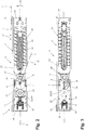
Figur 1- eine perspektivische Darstellung wesentlicher Komponenten eines Türschließers und
Figuren 2 und 3- Schnittdarstellungen der im Innern eines Türschließergehäuses eingebauten Türschließerkomponenten gemäß
Figur 1
- FIG. 1
- a perspective view of essential components of a door closer and
- FIGS. 2 and 3
- Sectional views of the built inside a door closer housing door closer components according to
FIG. 1 ,
Ausweislich der
An dem Türschließergehäuse 2 ist als wesentliche Komponente eines Schließerantriebes 6 eine Schließerwelle 7 um eine geometrische Achse 8 drehbar gelagert. In gewohnter Weise ist die Schließerwelle 7 über einen in
Weitere Bestandteile des Schließerantriebes 6 sind eine Schließerfedereinheit 10 bestehend aus einer äußeren Schließerfeder 11 und einer inneren Schließerfeder 12, ein Federkolben 13, eine federkolbenseitige Stützrolle 14 sowie eine Federkolben-Antriebskontur 15.Further components of the
Die Schließerfedereinheit 10 ist zwischen dem Federkolben 13 und einem ersten Gehäusedeckel 16 des Türschließergehäuses 2 vorgespannt. Der Federkolben 13 ist an der Innenwand des Türschließergehäuses 2 in Richtung eines Doppelpfeils 17 beweglich geführt. Die federkolbenseitige Stützrolle 14 ist an der von der Schließerfedereinheit 10 abliegenden Seite des Federkolbens 13 um eine Rollen-Drehachse 18 drehbar gelagert. Die Rollen-Drehachse 18 verläuft parallel zu der Achse 8 der Schließerwelle 7 und liegt mit ihrer geometrischen Achse gleichfalls in der Längs-Mittelebene des Türschließergehäuses 2.The
Die Federkolben-Antriebskontur 15 wird von einem mit der Schließerwelle 7 einstückigen und materialeinheitlichen Außenbund 19 ausgebildet. Sie erstreckt sich über den in
Für den Schließerantrieb 6 des Türschließers 1 ist eine hydraulische Dämpfungseinrichtung 20 vorgesehen.For the
Die Dämpfungseinrichtung 20 umfasst einen Dämpfungskolben 21, eine dämpfungskolbenseitige Stützrolle 22, eine Rückstellfeder 23 sowie eine Dämpfungskolben-Antriebskontur 24.The damping
Ebenso wie der Federkolben 13 ist auch der Dämpfungskolben 21 an der Innenwand des Türschließergehäuses 2 in Richtung des Doppelpfeils 17 verschiebbar geführt. Die dämpfungskolbenseitige Stützrolle 22 ist an der von der Rückstellfeder 23 abliegenden Seite des Dämpfungskolbens 21 um eine parallel zu der Achse 8 der Schließerwelle 7 verlaufende Rollen-Drehachse 25 drehbar gelagert. Auch die geometrische Achse der Rollen-Drehachse 25 liegt in der Längs-Mittelebene des Türschließergehäuses 2.Like the
Unter der Wirkung der zwischen dem Dämpfungskolben 21 und einem zweiten Gehäusedeckel 26 des Türschließergehäuses 2 gespannten Rückstellfeder 23 liegt die dämpfungskolbenseitige Stützrolle 22 an der Dämpfungskolben-Antriebskontur 24 an.Under the action of the tensioned between the damping
Die Dämpfungskolben-Antriebskontur 24 umfasst zwei Antriebs-Teilkonturen 27, 28, die beide einstückig und materialeinheitlich mit der Schließerwelle 7 ausgebildet sind (
Entsprechend der Aufteilung der Dämpfungskolben-Antriebskontur 24 auf die Antriebs-Teilkonturen 27, 28 weist die dämpfungskolbenseitige Stützrolle 22 zwei entlang der Rollen-Drehachse 25 voneinander beabstandete Rollenabschnitte 29, 30 auf. In
Wie in
Die
Der Dämpfungskolben 21 an der dem Federkolben 13 gegenüberliegenden Seite der Schließerwelle 7 befindet sich entlang der Längs-Mittelebene des Türschließergehäuses 2 in seiner schließerwellenfernen Endposition. Die Rückstellfeder 23 ist zwischen dem Dämpfungskolben 21 und dem zweiten Gehäusedeckel 26 des Türschließergehäuses 2 gestaucht und drückt folglich den Dämpfungskolben 21 sowie die dämpfungskolbenseitige Stützrolle 22 in Richtung auf die Achse 8 der Schließerwelle 7. Ein Gehäuseraum 31 zwischen dem zweiten Gehäusedeckel 26 und dem Dämpfungskolben 21 weist sein minimales Volumen auf.The damping
Wird ausgehend von den Verhältnissen gemäß den
Aufgrund der Drehbewegung der Federkolben-Antriebskontur 15 in Drehöffnungsrichtung 32 rollt die federkolbenseitige Stützrolle 14 auf der Federkolben-Antriebskontur 15 ab. Infolge der Geometrie der Federkolben-Antriebskontur 15 verlagert sich dabei der Ort der Abstützung der federkolbenseitigen Stützrolle 14 an der Federkolben-Antriebskontur 15 von der Achse 8 der Schließerwelle 7 weg. Der Federkolben 13 wird daher durch die sich um die Achse 8 der Schließerwelle 7 drehende Federkolben-Antriebskontur 15 über die federkolbenseitige Stützrolle 14 in
In gewohnter Weise ist der Verlauf der Federkolben-Antriebskontur 15 um die Achse 8 der Schließerwelle 7 derart gewählt, dass der Achsabstand der Abstützung der federkolbenseitigen Stützrolle 14 an der Federkolben-Antriebskontur 15 mit zunehmendem Türöffnungswinkel zunimmt und folglich der Öffnungsbewegung des Türflügels 3 von der Schließerfedereinheit 10 ein mit zunehmendem Türöffnungswinkel abnehmender Widerstand entgegengesetzt wird.In the usual way, the course of the spring
Bei der Spann-Drehbewegung der Federkolben-Antriebskontur 15 in der Drehöffnungsrichtung 32 rollt die federkolbenseitige Stützrolle 14 zunächst auf einem um die Achse 8 der Schließerwelle 7 verlaufenden Umfangsabschnitt der Federkolben-Antriebskontur 15 ab, deren Höhe längs der Achse 8 der Schließerwelle 7 der Höhe der federkolbenseitigen Stützrolle 14 in Richtung der Rollen-Drehachse 18 entspricht. Mit Erreichen des in
Mit der Drehbewegung der Schließerwelle 7 und der Federkolben-Antriebskontur 15 in der Drehöffnungsrichtung 32 geht eine gleichgerichtete Drehbewegung der Dämpfungskolben-Antriebskontur 24 einher. Dabei rollt die dämpfungskolbenseitige Stützrolle 22 mit den Rollenabschnitten 29, 30 auf den Antriebs-Teilkonturen 27, 28 der Dämpfungskolben-Antriebskontur 24 ab. In der Ausgangssituation bei geschlossenem Türflügel 3 (
Mit der in den
Wird der maximal geöffnete Türflügel 3 freigegeben, so bewegt sich der Federkolben 13 unter der Wirkung der ihn beaufschlagenden Schließerfedereinheit 10 in Richtung auf seine Ausgangsposition gemäß den
Mit der Drehbewegung der Federkolben-Antriebskontur 15 entgegen der Drehöffnungsrichtung 32 verbunden ist eine gleichgerichtete Drehbewegung der Dämpfungskolben-Antriebskontur 24 um die Achse 8 der Schließerwelle 7. Die Dämpfungskolben-Antriebskontur 24 beaufschlagt dabei die dämpfungskolbenseitige Stützrolle 22 und über diese den Dämpfungskolben 21. Infolge der Geometrie der Dämpfungskolben-Antriebskontur 24, d.h. infolge der mit der fortschreitenden Schließbewegung des Türflügels 3 verbundenen Zunahme des Achsabstandes der Abstützung der dämpfungskolbenseitigen Stützrolle 22 an der Dämpfungskolben-Antriebskontur 24, bewegt sich der Dämpfungskolben 21 aus seiner schließerwellennahen Position zurück in seine Ausgangsposition gemäß den
Sowohl die Wirkungslinie der zwischen der federkolbenseitigen Stützrolle 14 und dem Federkolben 13 übertragenen Kräfte als auch die Wirkungslinie der zwischen der dämpfungskolbenseitigen Stützrolle 22 und dem Dämpfungskolben 21 übertragenen Kräfte verläuft weitestgehend entlang der Längs-Mittelebene des Türschließergehäuses 2, die eine Symmetrieebene des Federkolbens 13 und des Dämpfungskolbens 21 bildet. Aufgrund der symmetrischen Krafteinleitung wird eine Schrägstellung des Federkolbens 13 und des Dämpfungskolbens 21 im Innern des Türschließergehäuses 2 und eine damit verbundenen Erhöhung der Reibung zwischen dem Federkolben 13 und dem Dämpfungskolben 21 einerseits und der Innenwand des Türschließergehäuses 2 andererseits vermieden. Auf diese Art und Weise wird der Verschleiß an den beteiligten Türschließerkomponenten minimiert und ein hoher Wirkungsgrad des Schließerantriebes 6 gewährleistet. Both the line of action of the transmitted between the spring piston
Claims (8)
- Door closer having a closer drive (6) and having a damping device (20) therefor,• wherein the closer drive (6) has a closer shaft (7), a closer spring unit (10), a spring piston (13) and a spring piston drive contour (15) which is provided between the closer shaft (7) and the spring piston (13),• wherein the damping device (20) has a damping means, a damping piston (21) and a damping piston drive contour (24) which is provided between the closer shaft (7) and the damping piston (21),• wherein the spring piston drive contour (15) and the damping piston drive contour (24) are coupled in terms of driving to each other and to the closer shaft (7) and can be rotated about a contour rotation axis (8) and extend, being arranged opposite each other at the contour rotation axis (8), in each case over a peripheral angle (α, β) about the contour rotation axis (8),• wherein as a result of a rotation of the closer shaft (7) in a rotation opening direction (32) the spring piston drive contour (15) rotates with a tensioning rotation movement about the contour rotation axis (8) and in this instance in the event of a rotation over the peripheral angle (α) of the spring piston drive contour (15) acts on the spring piston (13) which is arranged at one side of the contour rotation axis (8) and moves it in a radial direction of the contour rotation axis (8) with the closer spring unit (10) being tensioned,• wherein, after the rotation of the closer shaft (7) in the rotation opening direction (32), the spring piston (13) under the action of the relaxing closer spring unit (10) moves back in the radial direction of the contour rotation axis (8) and, with the spring piston (13) acting on the spring piston drive contour (15), rotates the damping piston drive contour (24) with a damping rotation movement directed counter to the tensioning rotation movement of the spring piston drive contour (15) about the contour rotation axis (8), wherein the damping piston drive contour (24) which is rotated with the damping rotation movement about the contour rotation axis (8) with a rotation over the peripheral angle (ß) of the damping piston drive contour (24) acts on the damping piston (21) which is arranged at the side of the contour rotation axis (8) remote from the spring piston (13) and moves it counter to a resistance which is applied by the damping means in the radial direction of the contour rotation axis (8), and• wherein the spring piston drive contour (15) and the damping piston drive contour (24) are arranged so as to be offset relative to each other along the contour rotation axis (8),characterised in that the spring piston drive contour (15) and the damping piston drive contour (24) extend with mutual overlapping of the peripheral angles (α, β) thereof about the contour rotation axis (8).
- Door closer according to claim 1, characterised in that the contour rotation axis (8) is formed by an axis of the closer shaft (7).
- Door closer according to either of the preceding claims, characterised in that the mutual action of the spring piston drive contour (15) and the spring piston (13) and/or the mutual action of the damping piston drive contour (24) and the damping piston (21) is carried out at the piston side in a symmetrical manner.
- Door closer according to any one of the preceding claims, characterised in that the spring piston drive contour (15) is supported on the spring piston (13) by means of a spring-piston-side support roller (14) and/or the damping piston drive contour (24) is supported on the damping piston (21) by means of a damping-piston-side support roller (22), wherein the spring-piston-side support roller (14) and the damping-piston-side support roller (22) each have a roller rotation axis (18, 25) which extends parallel with the contour rotation axis (8).
- Door closer according to any one of the preceding claims, characterised in that the damping piston drive contour (24) is constructed in several parts and comprises a plurality of drive part-contours (27, 28), wherein drive part-contours (27, 28) of the damping piston drive contour (24) which are adjacent to each other along the contour rotation axis (8) are offset with respect to each other along the contour rotation axis (8) with an intermediate space being formed, and in that the spring piston drive contour (15) in the region of the overlapping of the peripheral angle (α) thereof with the peripheral angle (ß) of the damping piston drive contour (24) has at least one portion which extends about the contour rotation axis (8) and which has reduced height in the direction of the contour rotation axis (8) and which is arranged in an intermediate space between mutually adjacent drive part-contours (27, 28) of the damping piston drive contour (24).
- Door closer according to claim 5, characterised in that the damping piston drive contour (24) is supported on the damping piston (21) by means of a damping-piston-side support roller (22) which has a roller rotation axis (25) which extends parallel with the contour rotation axis (8), wherein the damping-piston-side support roller (22) has a number of axial roller portions (29, 30) which corresponds to the number of drive part-contours (27, 28) of the damping piston drive contour (24) which roller portions (29, 30) are offset with respect to each other along the roller rotation axis (25) with an intermediate space being formed between two mutually adjacent roller portions (29, 30), wherein the height of the intermediate space between two mutually adjacent roller portions (29, 30) is adapted to the height of the height-reduced portion of the spring piston drive contour (15), which portion is arranged in the intermediate space between the drive part-contours (27, 28) of the damping piston drive contour (24) with which the two mutually adjacent roller portions (29, 30) are associated.
- Door closer according to any one of the preceding claims, characterised in that the spring piston drive contour (15) is constructed in several parts and comprises a plurality of drive part-contours, wherein drive part-contours of the spring piston drive contour (15) which are adjacent to each other along the contour rotation axis (8) are offset with respect to each other along the contour rotation axis (8) with an intermediate space being formed, and in that the damping piston drive contour (24) in the region of the overlapping of the peripheral angle (ß) thereof with the peripheral angle (α) of the spring piston drive contour (15) has at least one portion which extends about the contour rotation axis (8) and which has reduced height in the direction of the contour rotation axis (8) and which is arranged in an intermediate space between mutually adjacent drive part-contours of the spring piston drive contour (15).
- Door closer according to claim 7, characterised in that the spring piston drive contour (15) is supported on the spring piston (13) by means of a spring-piston-side support roller (14) which has a roller rotation axis (18) which extends parallel with the contour rotation axis (8), wherein the spring-piston-side support roller (14) has a number of axial roller portions which corresponds to the number of drive part-contours of the spring piston drive contour (15) which roller portions are offset with respect to each other along the roller rotation axis (18) with an intermediate space being formed between two mutually adjacent roller portions (29, 30), wherein the height of the intermediate space between two mutually adjacent roller portions is adapted to the height of the height-reduced portion of the damping piston drive contour (24), which portion is arranged in the intermediate space between the drive part-contours of the spring piston drive contour (15) with which the two mutually adjacent roller portions are associated.
Applications Claiming Priority (2)
| Application Number | Priority Date | Filing Date | Title |
|---|---|---|---|
| DE202012003928U DE202012003928U1 (en) | 2012-04-18 | 2012-04-18 | door closers |
| PCT/EP2012/075418 WO2013156094A1 (en) | 2012-04-18 | 2012-12-13 | Door closer |
Publications (2)
| Publication Number | Publication Date |
|---|---|
| EP2839100A1 EP2839100A1 (en) | 2015-02-25 |
| EP2839100B1 true EP2839100B1 (en) | 2017-04-05 |
Family
ID=47504887
Family Applications (1)
| Application Number | Title | Priority Date | Filing Date |
|---|---|---|---|
| EP12810178.9A Active EP2839100B1 (en) | 2012-04-18 | 2012-12-13 | Door closer |
Country Status (3)
| Country | Link |
|---|---|
| EP (1) | EP2839100B1 (en) |
| DE (1) | DE202012003928U1 (en) |
| WO (1) | WO2013156094A1 (en) |
Families Citing this family (5)
| Publication number | Priority date | Publication date | Assignee | Title |
|---|---|---|---|---|
| DE102014101431A1 (en) * | 2014-02-05 | 2015-08-06 | Eco Schulte Gmbh & Co. Kg | Door closer with damping piston |
| DE202017101197U1 (en) | 2017-03-02 | 2018-06-05 | Gretsch-Unitas GmbH Baubeschläge | Device for closing a door leaf and door arrangement with such a device |
| DE102018108389B3 (en) | 2018-04-10 | 2019-10-02 | Gretsch-Unitas GmbH Baubeschläge | door closers |
| EP3922799A1 (en) * | 2020-06-10 | 2021-12-15 | dormakaba Deutschland GmbH | Door actuator |
| DE102021129628A1 (en) | 2021-11-15 | 2023-05-17 | Gretsch-Unitas GmbH Baubeschläge | door closer |
Family Cites Families (3)
| Publication number | Priority date | Publication date | Assignee | Title |
|---|---|---|---|---|
| IT251019Y1 (en) | 2000-03-13 | 2003-11-04 | Fev Italia Archal S R L | AIR DOOR CLOSER PROVIDED WITH PERFECT ROTATION VEHICLES. |
| GB2479145A (en) * | 2010-03-29 | 2011-10-05 | Ingersoll Rand Security Technologies Ltd | Door closer having two springs |
| SI2746508T1 (en) * | 2010-09-06 | 2019-01-31 | In & Tec S.R.L. | Door closing hinge, particularly for glass doors |
-
2012
- 2012-04-18 DE DE202012003928U patent/DE202012003928U1/en not_active Expired - Lifetime
- 2012-12-13 EP EP12810178.9A patent/EP2839100B1/en active Active
- 2012-12-13 WO PCT/EP2012/075418 patent/WO2013156094A1/en active Application Filing
Also Published As
| Publication number | Publication date |
|---|---|
| DE202012003928U1 (en) | 2013-07-22 |
| WO2013156094A1 (en) | 2013-10-24 |
| EP2839100A1 (en) | 2015-02-25 |
Similar Documents
| Publication | Publication Date | Title |
|---|---|---|
| EP2539528B1 (en) | Lifting door having a movable door-leaf guide | |
| DE60207816T2 (en) | DOOR CLOSER | |
| EP2737152B1 (en) | Lifting door having a movable door leaf guide | |
| EP2839100B1 (en) | Door closer | |
| CH663261A5 (en) | SLIDING VALVE. | |
| EP3545158B1 (en) | Roller door | |
| DE102005049584A1 (en) | High-speed industrial rolling gate | |
| EP0146693A2 (en) | Door closer | |
| EP1500766A2 (en) | Bifold flap or door lifting apparatus | |
| DE202005015166U1 (en) | Door for bus or tram to be swiveled and slid to side for opening, comprises locking arrangement for spreading lever | |
| DE4038720A1 (en) | Upper door closer unit with slide rail bar - involves symmetrical construction of lift curve plate and use of assembly plate with corresp. bolts | |
| EP3004504B1 (en) | Door closer for a wing of a door or window | |
| DE19922916A1 (en) | Door closer with drive for closing door casement has spring piston and damping piston mounted rotationally secured relative to stroke cam plate through interaction with drive housing | |
| WO2019091969A1 (en) | Wing fitting for a piece of furniture, side wall of a body of a piece of furniture and piece of furniture comprising a side wall | |
| DE1191257B (en) | Hinge with compression spring for weight compensation of leaves | |
| EP3243990A1 (en) | Drive for a door | |
| AT510971B1 (en) | DEVICE FOR CONTROLLING THE CLOSURE OF DOUBLE SLEEPING DOORS | |
| EP3293343B1 (en) | Trigger aid for a seal of a hinged door | |
| DE4239219C2 (en) | Automatic door closer | |
| EP3763911B1 (en) | Guide rail device for a rolling gate or rolling grille | |
| DE6901279U (en) | DOOR CLOSER | |
| DE4217640C2 (en) | Hinge, especially for furniture doors | |
| DE4439475C1 (en) | Window mechanism for slide and tilt action | |
| DE2932865C2 (en) | ||
| EP2784258A2 (en) | Retraction device for a wing of a door or a window |
Legal Events
| Date | Code | Title | Description |
|---|---|---|---|
| PUAI | Public reference made under article 153(3) epc to a published international application that has entered the european phase |
Free format text: ORIGINAL CODE: 0009012 |
|
| 17P | Request for examination filed |
Effective date: 20140828 |
|
| AK | Designated contracting states |
Kind code of ref document: A1 Designated state(s): AL AT BE BG CH CY CZ DE DK EE ES FI FR GB GR HR HU IE IS IT LI LT LU LV MC MK MT NL NO PL PT RO RS SE SI SK SM TR |
|
| AX | Request for extension of the european patent |
Extension state: BA ME |
|
| DAX | Request for extension of the european patent (deleted) | ||
| GRAP | Despatch of communication of intention to grant a patent |
Free format text: ORIGINAL CODE: EPIDOSNIGR1 |
|
| INTG | Intention to grant announced |
Effective date: 20161025 |
|
| GRAS | Grant fee paid |
Free format text: ORIGINAL CODE: EPIDOSNIGR3 |
|
| GRAA | (expected) grant |
Free format text: ORIGINAL CODE: 0009210 |
|
| AK | Designated contracting states |
Kind code of ref document: B1 Designated state(s): AL AT BE BG CH CY CZ DE DK EE ES FI FR GB GR HR HU IE IS IT LI LT LU LV MC MK MT NL NO PL PT RO RS SE SI SK SM TR |
|
| REG | Reference to a national code |
Ref country code: GB Ref legal event code: FG4D Free format text: NOT ENGLISH |
|
| REG | Reference to a national code |
Ref country code: CH Ref legal event code: EP |
|
| REG | Reference to a national code |
Ref country code: AT Ref legal event code: REF Ref document number: 882003 Country of ref document: AT Kind code of ref document: T Effective date: 20170415 |
|
| REG | Reference to a national code |
Ref country code: IE Ref legal event code: FG4D Free format text: LANGUAGE OF EP DOCUMENT: GERMAN |
|
| REG | Reference to a national code |
Ref country code: DE Ref legal event code: R096 Ref document number: 502012009999 Country of ref document: DE |
|
| REG | Reference to a national code |
Ref country code: NL Ref legal event code: MP Effective date: 20170405 |
|
| REG | Reference to a national code |
Ref country code: LT Ref legal event code: MG4D |
|
| PG25 | Lapsed in a contracting state [announced via postgrant information from national office to epo] |
Ref country code: NL Free format text: LAPSE BECAUSE OF FAILURE TO SUBMIT A TRANSLATION OF THE DESCRIPTION OR TO PAY THE FEE WITHIN THE PRESCRIBED TIME-LIMIT Effective date: 20170405 |
|
| PG25 | Lapsed in a contracting state [announced via postgrant information from national office to epo] |
Ref country code: LT Free format text: LAPSE BECAUSE OF FAILURE TO SUBMIT A TRANSLATION OF THE DESCRIPTION OR TO PAY THE FEE WITHIN THE PRESCRIBED TIME-LIMIT Effective date: 20170405 Ref country code: ES Free format text: LAPSE BECAUSE OF FAILURE TO SUBMIT A TRANSLATION OF THE DESCRIPTION OR TO PAY THE FEE WITHIN THE PRESCRIBED TIME-LIMIT Effective date: 20170405 Ref country code: HR Free format text: LAPSE BECAUSE OF FAILURE TO SUBMIT A TRANSLATION OF THE DESCRIPTION OR TO PAY THE FEE WITHIN THE PRESCRIBED TIME-LIMIT Effective date: 20170405 Ref country code: NO Free format text: LAPSE BECAUSE OF FAILURE TO SUBMIT A TRANSLATION OF THE DESCRIPTION OR TO PAY THE FEE WITHIN THE PRESCRIBED TIME-LIMIT Effective date: 20170705 Ref country code: FI Free format text: LAPSE BECAUSE OF FAILURE TO SUBMIT A TRANSLATION OF THE DESCRIPTION OR TO PAY THE FEE WITHIN THE PRESCRIBED TIME-LIMIT Effective date: 20170405 Ref country code: GR Free format text: LAPSE BECAUSE OF FAILURE TO SUBMIT A TRANSLATION OF THE DESCRIPTION OR TO PAY THE FEE WITHIN THE PRESCRIBED TIME-LIMIT Effective date: 20170706 |
|
| PG25 | Lapsed in a contracting state [announced via postgrant information from national office to epo] |
Ref country code: RS Free format text: LAPSE BECAUSE OF FAILURE TO SUBMIT A TRANSLATION OF THE DESCRIPTION OR TO PAY THE FEE WITHIN THE PRESCRIBED TIME-LIMIT Effective date: 20170405 Ref country code: BG Free format text: LAPSE BECAUSE OF FAILURE TO SUBMIT A TRANSLATION OF THE DESCRIPTION OR TO PAY THE FEE WITHIN THE PRESCRIBED TIME-LIMIT Effective date: 20170705 Ref country code: SE Free format text: LAPSE BECAUSE OF FAILURE TO SUBMIT A TRANSLATION OF THE DESCRIPTION OR TO PAY THE FEE WITHIN THE PRESCRIBED TIME-LIMIT Effective date: 20170405 Ref country code: IS Free format text: LAPSE BECAUSE OF FAILURE TO SUBMIT A TRANSLATION OF THE DESCRIPTION OR TO PAY THE FEE WITHIN THE PRESCRIBED TIME-LIMIT Effective date: 20170805 Ref country code: LV Free format text: LAPSE BECAUSE OF FAILURE TO SUBMIT A TRANSLATION OF THE DESCRIPTION OR TO PAY THE FEE WITHIN THE PRESCRIBED TIME-LIMIT Effective date: 20170405 Ref country code: PL Free format text: LAPSE BECAUSE OF FAILURE TO SUBMIT A TRANSLATION OF THE DESCRIPTION OR TO PAY THE FEE WITHIN THE PRESCRIBED TIME-LIMIT Effective date: 20170405 |
|
| REG | Reference to a national code |
Ref country code: DE Ref legal event code: R097 Ref document number: 502012009999 Country of ref document: DE |
|
| PG25 | Lapsed in a contracting state [announced via postgrant information from national office to epo] |
Ref country code: CZ Free format text: LAPSE BECAUSE OF FAILURE TO SUBMIT A TRANSLATION OF THE DESCRIPTION OR TO PAY THE FEE WITHIN THE PRESCRIBED TIME-LIMIT Effective date: 20170405 Ref country code: SK Free format text: LAPSE BECAUSE OF FAILURE TO SUBMIT A TRANSLATION OF THE DESCRIPTION OR TO PAY THE FEE WITHIN THE PRESCRIBED TIME-LIMIT Effective date: 20170405 Ref country code: DK Free format text: LAPSE BECAUSE OF FAILURE TO SUBMIT A TRANSLATION OF THE DESCRIPTION OR TO PAY THE FEE WITHIN THE PRESCRIBED TIME-LIMIT Effective date: 20170405 Ref country code: EE Free format text: LAPSE BECAUSE OF FAILURE TO SUBMIT A TRANSLATION OF THE DESCRIPTION OR TO PAY THE FEE WITHIN THE PRESCRIBED TIME-LIMIT Effective date: 20170405 Ref country code: RO Free format text: LAPSE BECAUSE OF FAILURE TO SUBMIT A TRANSLATION OF THE DESCRIPTION OR TO PAY THE FEE WITHIN THE PRESCRIBED TIME-LIMIT Effective date: 20170405 |
|
| PLBE | No opposition filed within time limit |
Free format text: ORIGINAL CODE: 0009261 |
|
| STAA | Information on the status of an ep patent application or granted ep patent |
Free format text: STATUS: NO OPPOSITION FILED WITHIN TIME LIMIT |
|
| PG25 | Lapsed in a contracting state [announced via postgrant information from national office to epo] |
Ref country code: IT Free format text: LAPSE BECAUSE OF FAILURE TO SUBMIT A TRANSLATION OF THE DESCRIPTION OR TO PAY THE FEE WITHIN THE PRESCRIBED TIME-LIMIT Effective date: 20170405 Ref country code: SM Free format text: LAPSE BECAUSE OF FAILURE TO SUBMIT A TRANSLATION OF THE DESCRIPTION OR TO PAY THE FEE WITHIN THE PRESCRIBED TIME-LIMIT Effective date: 20170405 |
|
| 26N | No opposition filed |
Effective date: 20180108 |
|
| PG25 | Lapsed in a contracting state [announced via postgrant information from national office to epo] |
Ref country code: SI Free format text: LAPSE BECAUSE OF FAILURE TO SUBMIT A TRANSLATION OF THE DESCRIPTION OR TO PAY THE FEE WITHIN THE PRESCRIBED TIME-LIMIT Effective date: 20170405 |
|
| REG | Reference to a national code |
Ref country code: CH Ref legal event code: PL |
|
| GBPC | Gb: european patent ceased through non-payment of renewal fee |
Effective date: 20171213 |
|
| REG | Reference to a national code |
Ref country code: IE Ref legal event code: MM4A |
|
| PG25 | Lapsed in a contracting state [announced via postgrant information from national office to epo] |
Ref country code: LU Free format text: LAPSE BECAUSE OF NON-PAYMENT OF DUE FEES Effective date: 20171213 Ref country code: MT Free format text: LAPSE BECAUSE OF FAILURE TO SUBMIT A TRANSLATION OF THE DESCRIPTION OR TO PAY THE FEE WITHIN THE PRESCRIBED TIME-LIMIT Effective date: 20170405 |
|
| REG | Reference to a national code |
Ref country code: FR Ref legal event code: ST Effective date: 20180831 |
|
| REG | Reference to a national code |
Ref country code: BE Ref legal event code: MM Effective date: 20171231 |
|
| PG25 | Lapsed in a contracting state [announced via postgrant information from national office to epo] |
Ref country code: IE Free format text: LAPSE BECAUSE OF NON-PAYMENT OF DUE FEES Effective date: 20171213 Ref country code: FR Free format text: LAPSE BECAUSE OF NON-PAYMENT OF DUE FEES Effective date: 20180102 |
|
| PG25 | Lapsed in a contracting state [announced via postgrant information from national office to epo] |
Ref country code: BE Free format text: LAPSE BECAUSE OF NON-PAYMENT OF DUE FEES Effective date: 20171231 Ref country code: CH Free format text: LAPSE BECAUSE OF NON-PAYMENT OF DUE FEES Effective date: 20171231 Ref country code: LI Free format text: LAPSE BECAUSE OF NON-PAYMENT OF DUE FEES Effective date: 20171231 Ref country code: GB Free format text: LAPSE BECAUSE OF NON-PAYMENT OF DUE FEES Effective date: 20171213 |
|
| REG | Reference to a national code |
Ref country code: AT Ref legal event code: MM01 Ref document number: 882003 Country of ref document: AT Kind code of ref document: T Effective date: 20171213 |
|
| PG25 | Lapsed in a contracting state [announced via postgrant information from national office to epo] |
Ref country code: AT Free format text: LAPSE BECAUSE OF NON-PAYMENT OF DUE FEES Effective date: 20171213 |
|
| PG25 | Lapsed in a contracting state [announced via postgrant information from national office to epo] |
Ref country code: MC Free format text: LAPSE BECAUSE OF FAILURE TO SUBMIT A TRANSLATION OF THE DESCRIPTION OR TO PAY THE FEE WITHIN THE PRESCRIBED TIME-LIMIT Effective date: 20170405 Ref country code: HU Free format text: LAPSE BECAUSE OF FAILURE TO SUBMIT A TRANSLATION OF THE DESCRIPTION OR TO PAY THE FEE WITHIN THE PRESCRIBED TIME-LIMIT; INVALID AB INITIO Effective date: 20121213 |
|
| PG25 | Lapsed in a contracting state [announced via postgrant information from national office to epo] |
Ref country code: CY Free format text: LAPSE BECAUSE OF FAILURE TO SUBMIT A TRANSLATION OF THE DESCRIPTION OR TO PAY THE FEE WITHIN THE PRESCRIBED TIME-LIMIT Effective date: 20170405 |
|
| PG25 | Lapsed in a contracting state [announced via postgrant information from national office to epo] |
Ref country code: MK Free format text: LAPSE BECAUSE OF FAILURE TO SUBMIT A TRANSLATION OF THE DESCRIPTION OR TO PAY THE FEE WITHIN THE PRESCRIBED TIME-LIMIT Effective date: 20170405 |
|
| PG25 | Lapsed in a contracting state [announced via postgrant information from national office to epo] |
Ref country code: TR Free format text: LAPSE BECAUSE OF FAILURE TO SUBMIT A TRANSLATION OF THE DESCRIPTION OR TO PAY THE FEE WITHIN THE PRESCRIBED TIME-LIMIT Effective date: 20170405 |
|
| PG25 | Lapsed in a contracting state [announced via postgrant information from national office to epo] |
Ref country code: PT Free format text: LAPSE BECAUSE OF FAILURE TO SUBMIT A TRANSLATION OF THE DESCRIPTION OR TO PAY THE FEE WITHIN THE PRESCRIBED TIME-LIMIT Effective date: 20170405 |
|
| PG25 | Lapsed in a contracting state [announced via postgrant information from national office to epo] |
Ref country code: AL Free format text: LAPSE BECAUSE OF FAILURE TO SUBMIT A TRANSLATION OF THE DESCRIPTION OR TO PAY THE FEE WITHIN THE PRESCRIBED TIME-LIMIT Effective date: 20170405 |
|
| P01 | Opt-out of the competence of the unified patent court (upc) registered |
Effective date: 20230630 |
|
| PGFP | Annual fee paid to national office [announced via postgrant information from national office to epo] |
Ref country code: DE Payment date: 20231214 Year of fee payment: 12 |